Embed Size (px)
Citation preview

www.scientistsinschool.ca 1
Gearing Up: Fun with Pulleys and Gears
How simple really is the world of science around us? Well, if we take a closer look, we will see evidence of simple machines such as pulleys and gears in the everyday things we use, from something as basic as a can opener to the washing machine. Pulleys can provide many advantages such as helping us move things like the blinds in the classroom or the conveyor belt at the grocery store. Did you ever wonder how a roller coaster makes its way to the top of the hill? That’s right, gears and pulleys are there to help us once again! These machines help make it easier for us to do things. What would we ever have done without them? Background Information Work is the force, measured in Newtons (N), it takes to move a load across a distance. Using simple machines, such as pulleys and gears, can provide advantages to make work easier. Gears
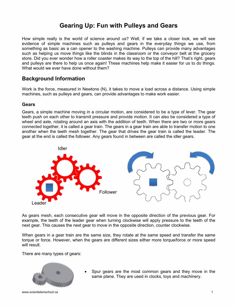
Gears, a simple machine moving in a circular motion, are considered to be a type of lever. The gear teeth push on each other to transmit pressure and provide motion. It can also be considered a type of wheel and axle, rotating around an axis with the addition of teeth. When there are two or more gears connected together, it is called a gear train. The gears in a gear train are able to transfer motion to one another when the teeth mesh together. The gear that drives the gear train is called the leader. The gear at the end is called the follower. Any gears found in between are called the idler gears.
As gears mesh, each consecutive gear will move in the opposite direction of the previous gear. For example, the teeth of the leader gear when turning clockwise will apply pressure to the teeth of the next gear. This causes the next gear to move in the opposite direction, counter clockwise. When gears in a gear train are the same size, they rotate at the same speed and transfer the same torque or force. However, when the gears are different sizes either more torque/force or more speed will result.
There are many types of gears:
• Spur gears are the most common gears and they move in the same plane. They are used in clocks, toys and machinery.
Leader
Idler
Follower
www.scientistsinschool.ca 2
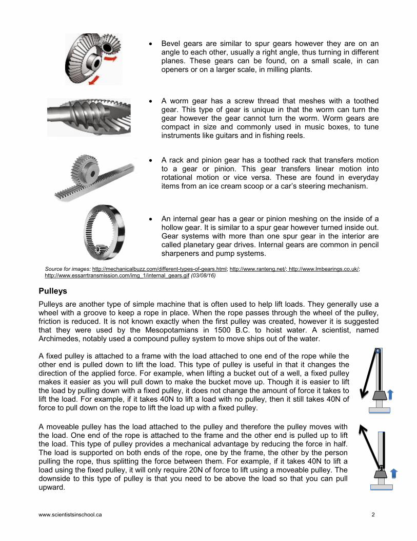
• Bevel gears are similar to spur gears however they are on an angle to each other, usually a right angle, thus turning in different planes. These gears can be found, on a small scale, in can openers or on a larger scale, in milling plants.
• A worm gear has a screw thread that meshes with a toothed gear. This type of gear is unique in that the worm can turn the gear however the gear cannot turn the worm. Worm gears are compact in size and commonly used in music boxes, to tune instruments like guitars and in fishing reels.
• A rack and pinion gear has a toothed rack that transfers motion
to a gear or pinion. This gear transfers linear motion into rotational motion or vice versa. These are found in everyday items from an ice cream scoop or a car’s steering mechanism.
• An internal gear has a gear or pinion meshing on the inside of a hollow gear. It is similar to a spur gear however turned inside out. Gear systems with more than one spur gear in the interior are called planetary gear drives. Internal gears are common in pencil sharpeners and pump systems.
Pulleys
Pulleys are another type of simple machine that is often used to help lift loads. They generally use a wheel with a groove to keep a rope in place. When the rope passes through the wheel of the pulley, friction is reduced. It is not known exactly when the first pulley was created, however it is suggested that they were used by the Mesopotamians in 1500 B.C. to hoist water. A scientist, named Archimedes, notably used a compound pulley system to move ships out of the water. A fixed pulley is attached to a frame with the load attached to one end of the rope while the other end is pulled down to lift the load. This type of pulley is useful in that it changes the direction of the applied force. For example, when lifting a bucket out of a well, a fixed pulley makes it easier as you will pull down to make the bucket move up. Though it is easier to lift the load by pulling down with a fixed pulley, it does not change the amount of force it takes to lift the load. For example, if it takes 40N to lift a load with no pulley, then it still takes 40N of force to pull down on the rope to lift the load up with a fixed pulley. A moveable pulley has the load attached to the pulley and therefore the pulley moves with the load. One end of the rope is attached to the frame and the other end is pulled up to lift the load. This type of pulley provides a mechanical advantage by reducing the force in half. The load is supported on both ends of the rope, one by the frame, the other by the person pulling the rope, thus splitting the force between them. For example, if it takes 40N to lift a load using the fixed pulley, it will only require 20N of force to lift using a moveable pulley. The downside to this type of pulley is that you need to be above the load so that you can pull upward.
Source for images: http://mechanicalbuzz.com/different-types-of-gears.html; http://www.ranteng.net/; http://www.lmbearings.co.uk/; http://www.essarrtransmission.com/img_1/internal_gears.gif (03/08/16)
www.scientistsinschool.ca 3
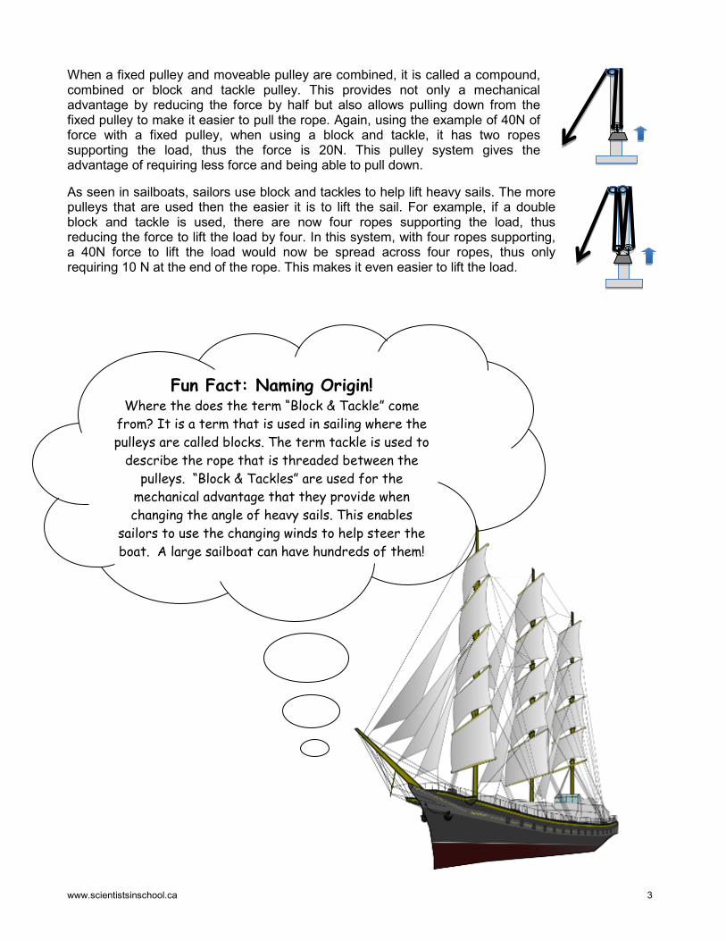
When a fixed pulley and moveable pulley are combined, it is called a compound, combined or block and tackle pulley. This provides not only a mechanical advantage by reducing the force by half but also allows pulling down from the fixed pulley to make it easier to pull the rope. Again, using the example of 40N of force with a fixed pulley, when using a block and tackle, it has two ropes supporting the load, thus the force is 20N. This pulley system gives the advantage of requiring less force and being able to pull down.
As seen in sailboats, sailors use block and tackles to help lift heavy sails. The more pulleys that are used then the easier it is to lift the sail. For example, if a double block and tackle is used, there are now four ropes supporting the load, thus reducing the force to lift the load by four. In this system, with four ropes supporting, a 40N force to lift the load would now be spread across four ropes, thus only requiring 10 N at the end of the rope. This makes it even easier to lift the load.
Fun Fact: Naming Origin! Where the does the term “Block & Tackle” come
from? It is a term that is used in sailing where the pulleys are called blocks. The term tackle is used to
describe the rope that is threaded between the pulleys. “Block & Tackles” are used for the
mechanical advantage that they provide when changing the angle of heavy sails. This enables
sailors to use the changing winds to help steer the boat. A large sailboat can have hundreds of them!
www.scientistsinschool.ca 4
Activity 1: Was That A Lot of Work?
Time: 30-60 minutes Other Application: Language Key Terms: pulleys, mechanical advantage, work, force, distance Group Size: Individual Materials (per student): □ pencil
□ “Was That A Lot of Work?” datasheet
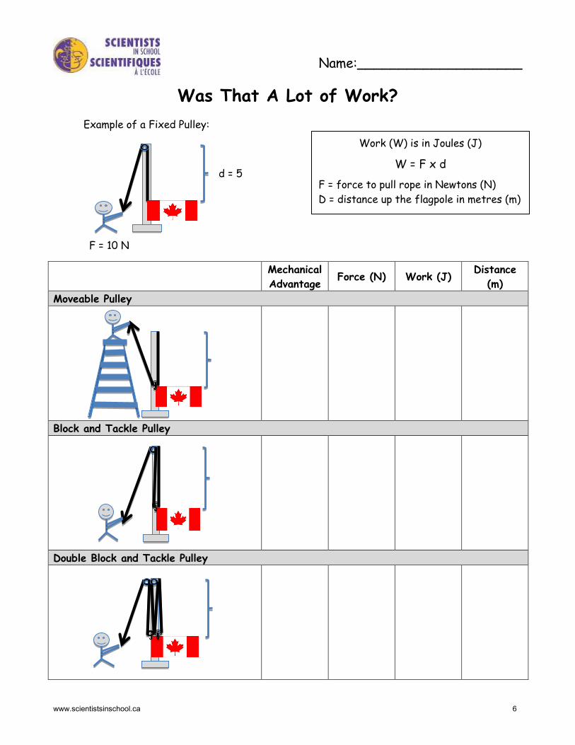
Learning Goal: Students will learn about different types of pulleys and mechanical advantage. The work-energy theorem, Work = Force x distance, can be used to investigate the characteristics of pulleys. Work is considered the displacement of the load, or the force required to move a load from one place to another. Mechanical advantage is a measurement of how much a simple machine multiplies a force. Procedure: 1. Hand out a “Was That A Lot of Work?” datasheet to each
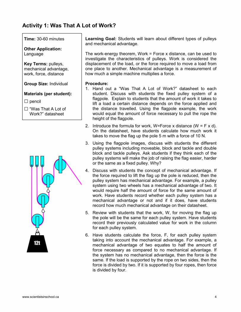
student. Discuss with students the fixed pulley system of a flagpole. Explain to students that the amount of work it takes to lift a load a certain distance depends on the force applied and the distance travelled. Using the flagpole example, the work would equal the amount of force necessary to pull the rope the height of the flagpole.
2. Introduce the formula for work, W=Force x distance (W = F x d). On the datasheet, have students calculate how much work it takes to move the flag up the pole 5 m with a force of 10 N.
3. Using the flagpole images, discuss with students the different pulley systems including moveable, block and tackle and double block and tackle pulleys. Ask students if they think each of the pulley systems will make the job of raising the flag easier, harder or the same as a fixed pulley. Why?
4. Discuss with students the concept of mechanical advantage. If the force required to lift the flag up the pole is reduced, then the pulley system has mechanical advantage. For example, a pulley system using two wheels has a mechanical advantage of two. It would require half the amount of force for the same amount of work. Have students record whether each pulley system has a mechanical advantage or not and if it does, have students record how much mechanical advantage on their datasheet.
5. Review with students that the work, W, for moving the flag up the pole will be the same for each pulley system. Have students record their previously calculated value for work in the column for each pulley system.
6. Have students calculate the force, F, for each pulley system taking into account the mechanical advantage. For example, a mechanical advantage of two equates to half the amount of force necessary as compared to no mechanical advantage. If the system has no mechanical advantage, then the force is the same. If the load is supported by the rope on two sides, then the force is divided by two. If it is supported by four ropes, then force is divided by four.
www.scientistsinschool.ca 5
7. Now that the students know the amount of work and the force, have them calculate the distance required to pull the rope. If W = F x d, then the formula to find distance is d = W / F.
8. Ask students to review their results and answer the following questions about the force and distance relationship: Which pulley system requires the least force? In that pulley system, what happens to the distance required to pull to lift the flag as compared to the other pulley systems? Therefore, when doing the same work and when a pulley system provides mechanical advantage, does the force to lift the flag increase or decrease? Does the distance travelled to pull the rope increase or decrease?
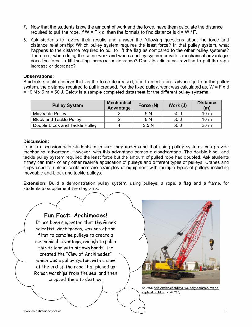
Observations: Students should observe that as the force decreased, due to mechanical advantage from the pulley system, the distance required to pull increased. For the fixed pulley, work was calculated as, W = F x d = 10 N x 5 m = 50 J. Below is a sample completed datasheet for the different pulley systems.
Pulley System Mechanical Advantage Force (N) Work (J) Distance
(m) Moveable Pulley 2 5 N 50 J 10 m Block and Tackle Pulley 2 5 N 50 J 10 m Double Block and Tackle Pulley 4 2.5 N 50 J 20 m
Discussion: Lead a discussion with students to ensure they understand that using pulley systems can provide mechanical advantage. However, with this advantage comes a disadvantage. The double block and tackle pulley system required the least force but the amount of pulled rope had doubled. Ask students if they can think of any other real-life application of pulleys and different types of pulleys. Cranes and ships used to unload containers are examples of equipment with multiple types of pulleys including moveable and block and tackle pulleys. Extension: Build a demonstration pulley system, using pulleys, a rope, a flag and a frame, for students to supplement the diagrams.
Source: http://zdanelspulleys.we ebly.com/real-world-application.html (25/07/16)
Fun Fact: Archimedes! It has been suggested that the Greek scientist, Archimedes, was one of the first to combine pulleys to create a
mechanical advantage, enough to pull a ship to land with his own hands! He created the “Claw of Archimedes”
which was a pulley system with a claw at the end of the rope that picked up
Roman warships from the sea, and then dropped them to destroy!
www.scientistsinschool.ca 6
Name:____________________
Was That A Lot of Work?
Mechanical Advantage Force (N) Work (J) Distance
(m) Moveable Pulley
Block and Tackle Pulley
Double Block and Tackle Pulley
Work (W) is in Joules (J)
W = F x d
F = force to pull rope in Newtons (N) D = distance up the flagpole in metres (m)
Example of a Fixed Pulley:
d = 5
F = 10 N
www.scientistsinschool.ca 7
Activity 2: Zipping Along with Pulleys
Time: 30-60 minutes Other Applications: Language, Social Studies Key Terms: pulley, gravity, friction, slope Group Size: 2-4 students Materials (per group): □ skipping rope or thicker
gauge rope
□ 3 large paper clips
□ string
□ disposable plastic cup
□ scissors
□ load (student choice)
□ sewing bobbin
□ bolt (to fit through sewing bobbin and be able to spin freely and with a length of 3 – 3.5 cm or 1 ¼ -1 ½ inches)
□ nuts (4 per bolt)
Learning Goal: Students will learn how a pulley can help reduce friction while using gravitational pull. Zip lines have been in use for years to help traverse from one point to another. The key components to a zip line are a cable and a pulley. The cable is attached at a higher point and the load moves to a lower point, in order to utilize gravity. A moveable pulley, which moves with the load, is normally used in order to reduce friction. Procedure: 1. Have one student per group bring in a skipping rope, a braided
rope or vinyl rope with a thickness that will fit loosely in the sewing bobbin.
2. Provide student groups with some of the materials including the skipping rope, disposable plastic cup, scissors, string and one paper clip. Have students tie one end of the rope to the final destination point on their zip line, such as the bottom of a chair or leg of a desk. This will be considered Point B. Point A will be the loose end of the rope and the highest point of the zip line.
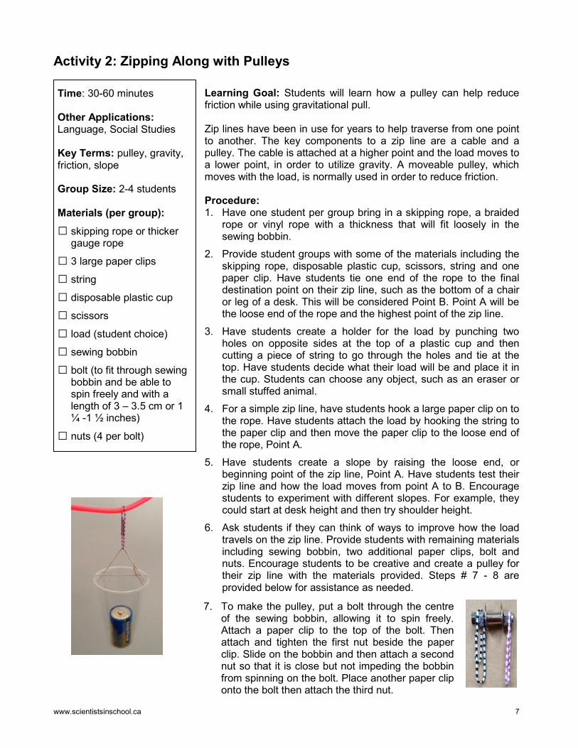
3. Have students create a holder for the load by punching two holes on opposite sides at the top of a plastic cup and then cutting a piece of string to go through the holes and tie at the top. Have students decide what their load will be and place it in the cup. Students can choose any object, such as an eraser or small stuffed animal.
4. For a simple zip line, have students hook a large paper clip on to the rope. Have students attach the load by hooking the string to the paper clip and then move the paper clip to the loose end of the rope, Point A.
5. Have students create a slope by raising the loose end, or beginning point of the zip line, Point A. Have students test their zip line and how the load moves from point A to B. Encourage students to experiment with different slopes. For example, they could start at desk height and then try shoulder height.
6. Ask students if they can think of ways to improve how the load travels on the zip line. Provide students with remaining materials including sewing bobbin, two additional paper clips, bolt and nuts. Encourage students to be creative and create a pulley for their zip line with the materials provided. Steps # 7 - 8 are provided below for assistance as needed.
7. To make the pulley, put a bolt through the centre of the sewing bobbin, allowing it to spin freely. Attach a paper clip to the top of the bolt. Then attach and tighten the first nut beside the paper clip. Slide on the bobbin and then attach a second nut so that it is close but not impeding the bobbin from spinning on the bolt. Place another paper clip onto the bolt then attach the third nut.
www.scientistsinschool.ca 8
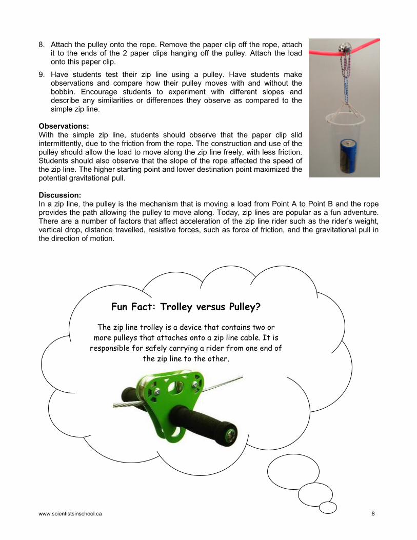
8. Attach the pulley onto the rope. Remove the paper clip off the rope, attach it to the ends of the 2 paper clips hanging off the pulley. Attach the load onto this paper clip.
9. Have students test their zip line using a pulley. Have students make observations and compare how their pulley moves with and without the bobbin. Encourage students to experiment with different slopes and describe any similarities or differences they observe as compared to the simple zip line.
Observations: With the simple zip line, students should observe that the paper clip slid intermittently, due to the friction from the rope. The construction and use of the pulley should allow the load to move along the zip line freely, with less friction. Students should also observe that the slope of the rope affected the speed of the zip line. The higher starting point and lower destination point maximized the potential gravitational pull. Discussion: In a zip line, the pulley is the mechanism that is moving a load from Point A to Point B and the rope provides the path allowing the pulley to move along. Today, zip lines are popular as a fun adventure. There are a number of factors that affect acceleration of the zip line rider such as the rider’s weight, vertical drop, distance travelled, resistive forces, such as force of friction, and the gravitational pull in the direction of motion.
Fun Fact: Trolley versus Pulley?
The zip line trolley is a device that contains two or more pulleys that attaches onto a zip line cable. It is
responsible for safely carrying a rider from one end of the zip line to the other.
www.scientistsinschool.ca 9
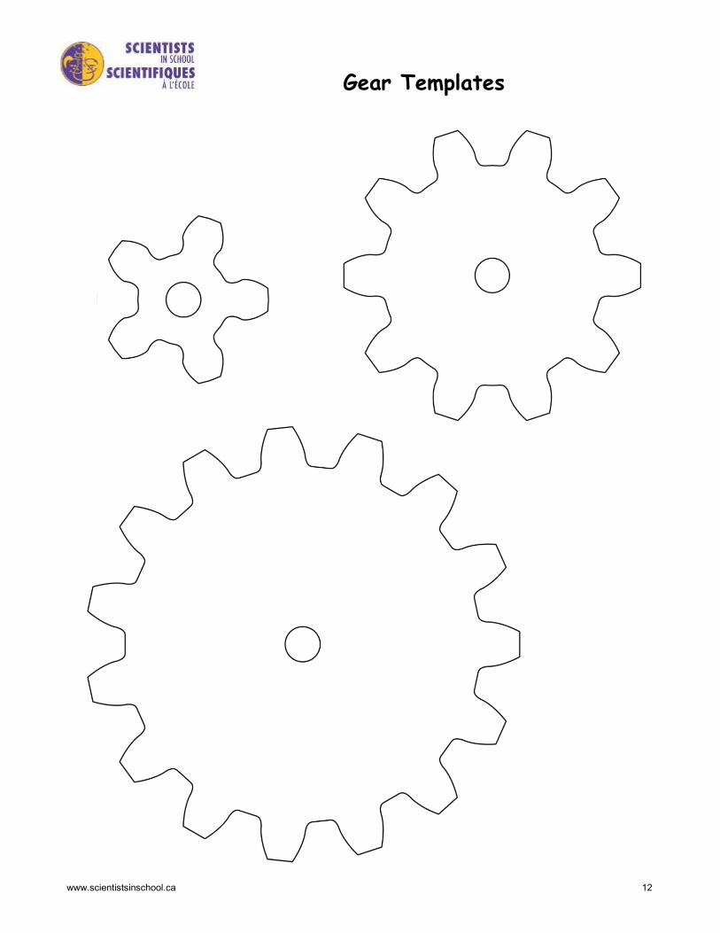
Activity 3: Gear Ratios
1. Time: 60-90 minutes Other Applications: Language, Math, Art Key Terms: gears, mechanical advantage, speed, ratio, fractions, torque, force Group Size: Individual Materials (per student): □ pencil
□ “Gear Templates”
□ marker
□ scissors
□ Bristol board, sturdy paper plates or boxboard
□ push pins
□ double-sided tape/tabs
□ stickers or markers
□ “Gear Ratios” datasheet
Learning Goal: Students will build a gear train and learn about gear ratios. When different sized gears mesh, there is a gear advantage. When a large gear turns a small gear, the small gear will rotate quicker. This advantage is called gearing up,. The speed that the small gear rotates is dependent on the number of teeth on each gear. This can be expressed as a gear ratio using the formula: Gear Ratio = Number of teeth of follower (smaller gear in this example) Number of teeth of leader (larger gear in this example) Procedure: 1. Have each student bring in an empty tissue box or shoe box. 2. Provide each student with a copy of “Gear Templates”. Have
students cut out each of the gear pieces. 3. Using the gear template pieces, have students trace the gears
onto pieces of boxboard, paper plates or Bristol board. Alternatively, glue the pieces onto the boxboard and cut out. Have students cut out each gear size; small, medium and large.
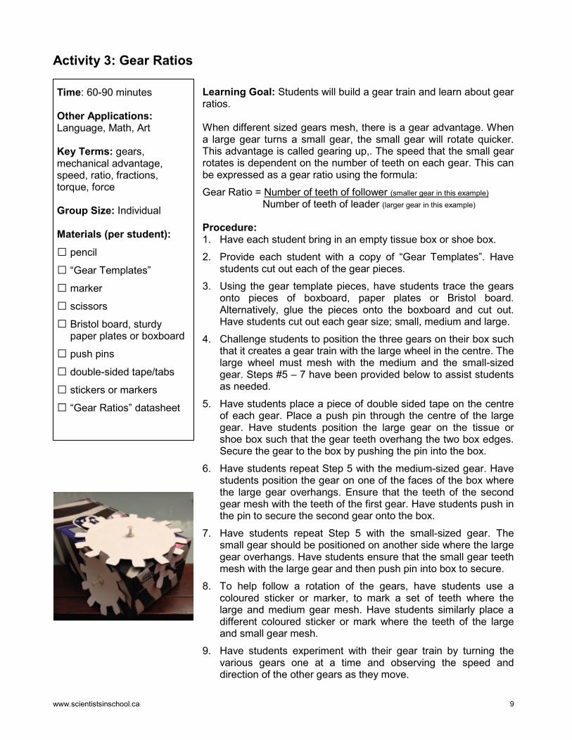
4. Challenge students to position the three gears on their box such that it creates a gear train with the large wheel in the centre. The large wheel must mesh with the medium and the small-sized gear. Steps #5 – 7 have been provided below to assist students as needed.
5. Have students place a piece of double sided tape on the centre of each gear. Place a push pin through the centre of the large gear. Have students position the large gear on the tissue or shoe box such that the gear teeth overhang the two box edges. Secure the gear to the box by pushing the pin into the box.
6. Have students repeat Step 5 with the medium-sized gear. Have students position the gear on one of the faces of the box where the large gear overhangs. Ensure that the teeth of the second gear mesh with the teeth of the first gear. Have students push in the pin to secure the second gear onto the box.
7. Have students repeat Step 5 with the small-sized gear. The small gear should be positioned on another side where the large gear overhangs. Have students ensure that the small gear teeth mesh with the large gear and then push pin into box to secure.
8. To help follow a rotation of the gears, have students use a coloured sticker or marker, to mark a set of teeth where the large and medium gear mesh. Have students similarly place a different coloured sticker or mark where the teeth of the large and small gear mesh.
9. Have students experiment with their gear train by turning the various gears one at a time and observing the speed and direction of the other gears as they move.
www.scientistsinschool.ca 10
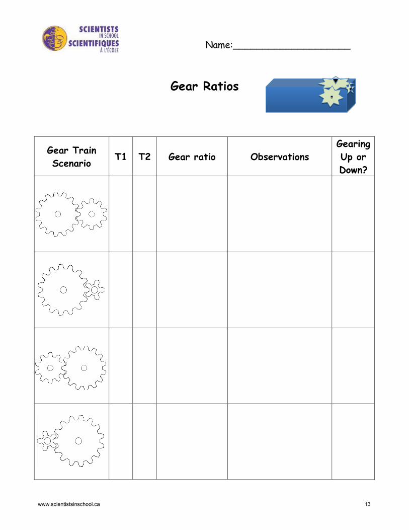
10. Provide each student with a “Gears Ratio” datasheet. Explain to students that the gear that drives
the gear train is called the leader gear. The gear at the end of the gear train is the follower gear. Have students record the number of teeth on each gear. T1 represents the number of teeth on the leader gear and T2 represents the number of teeth on the follower gear.
11. The gear ratio can be calculated as the number of teeth of the follower gear divided by the number of teeth of the leader gear (T2/T1 or T2:T1). Have students calculate the gear ratio using the number of teeth of the gears for the four different scenarios on the datasheet. Tell students that the leader gear is the first gear depicted in each image.
12. Have students experiment with each scenario on their model. Have students record how many turns of one gear cause how many turns of the other gear and express it as a ratio. For example, 1 turn of the large gear cause 3 turns of the small gear, which is 1:3. Ask students if there is a relationship between the gear ratio they calculated based on the number of teeth of the gears as compared to their observations as to the number of turns the gears move.
13. Have students also observe the speed of the follower gear – is it faster or slower than the leader gear? Gearing up is terminology that indicates the follower gear rotates faster. Gearing down indicates the follower gear is rotating slower. Have students record whether the gear train is gearing up or down for each scenario. Ask students when the gear ratio is greater than 1, if it is gearing up or down. Ask students when the gear ratio is less than 1, if it is gearing up or down.
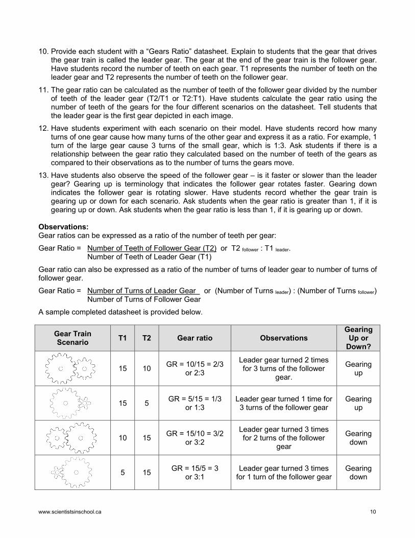
Observations: Gear ratios can be expressed as a ratio of the number of teeth per gear: Gear Ratio = Number of Teeth of Follower Gear (T2) or T2 follower : T1 leader. Number of Teeth of Leader Gear (T1) Gear ratio can also be expressed as a ratio of the number of turns of leader gear to number of turns of follower gear. Gear Ratio = Number of Turns of Leader Gear or (Number of Turns leader) : (Number of Turns follower)
Number of Turns of Follower Gear A sample completed datasheet is provided below.
Gear Train Scenario T1 T2 Gear ratio Observations
Gearing Up or
Down?
15 10 GR = 10/15 = 2/3 or 2:3
Leader gear turned 2 times for 3 turns of the follower
gear.
Gearing up
15 5 GR = 5/15 = 1/3 or 1:3
Leader gear turned 1 time for 3 turns of the follower gear
Gearing up
10 15 GR = 15/10 = 3/2 or 3:2
Leader gear turned 3 times for 2 turns of the follower
gear
Gearing down
5 15 GR = 15/5 = 3 or 3:1
Leader gear turned 3 times for 1 turn of the follower gear
Gearing down
www.scientistsinschool.ca 11
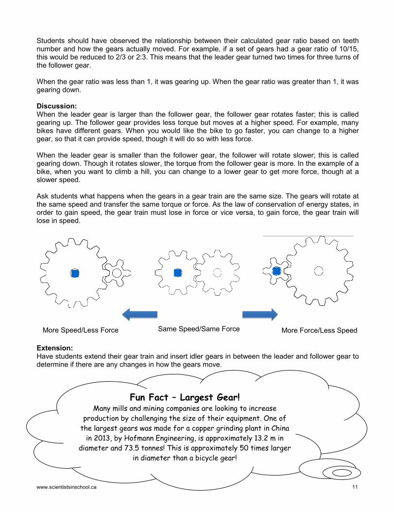
Students should have observed the relationship between their calculated gear ratio based on teeth number and how the gears actually moved. For example, if a set of gears had a gear ratio of 10/15, this would be reduced to 2/3 or 2:3. This means that the leader gear turned two times for three turns of the follower gear. When the gear ratio was less than 1, it was gearing up. When the gear ratio was greater than 1, it was gearing down. Discussion: When the leader gear is larger than the follower gear, the follower gear rotates faster; this is called gearing up. The follower gear provides less torque but moves at a higher speed. For example, many bikes have different gears. When you would like the bike to go faster, you can change to a higher gear, so that it can provide speed, though it will do so with less force. When the leader gear is smaller than the follower gear, the follower will rotate slower; this is called gearing down. Though it rotates slower, the torque from the follower gear is more. In the example of a bike, when you want to climb a hill, you can change to a lower gear to get more force, though at a slower speed. Ask students what happens when the gears in a gear train are the same size. The gears will rotate at the same speed and transfer the same torque or force. As the law of conservation of energy states, in order to gain speed, the gear train must lose in force or vice versa, to gain force, the gear train will lose in speed.
Extension: Have students extend their gear train and insert idler gears in between the leader and follower gear to determine if there are any changes in how the gears move.
More Speed/Less Force Same Speed/Same Force More Force/Less Speed
Fun Fact – Largest Gear! Many mills and mining companies are looking to increase
production by challenging the size of their equipment. One of the largest gears was made for a copper grinding plant in China
in 2013, by Hofmann Engineering, is approximately 13.2 m in diameter and 73.5 tonnes! This is approximately 50 times larger
in diameter than a bicycle gear!
www.scientistsinschool.ca 13
Name:____________________
Gear Ratios
Gear Train Scenario T1 T2 Gear ratio Observations
Gearing Up or Down?
www.scientistsinschool.ca 14
Activity 4: Move It in a Pinch with a Winch!
Time: 60-90 minutes Other Application: Art, Language, Social Studies Key Terms: pulley, gravity, gear, load, winch, drum Group Size: 2-4 students Materials: □ student collection of clean
recyclables such as paper towel rolls, cans, cups, bottles, ribbon spools, thread spools and small boxes
□ string
□ masking tape
□ straws
□ wooden dowels
□ pencils
□ scissors
Learning Goal: Students will learn about pulleys and gears as they build a winch to move a load. Winches are machines that combine different simple machines to create a mechanical device that can reel a load in or out. Procedure: 1. Have students collect recyclables such as paper towel rolls,
cans, cups, ribbon spools, thread spools and small boxes, such as tissue boxes.
2. Create a supply station using recyclables as well as string, masking tape, dowels, pencils, and straws.
3. Explain to students that each group will be creating their own winch for the purpose of moving a load. Have student groups decide on the purpose of their winch and choose a load that is lightweight, such as a small toy or eraser.
4. Have students brainstorm ideas to build a stand to hold the axle of the winch. Have students create their stand using recyclables, such as cups, boxes, water bottles and paper towel rolls. Have students secure the stand to a base, such as a desk.
5. The winch drum, the cylinder that winds up string, can be made from items such as a ribbon spool, thread spool or can. Have students create their winch drum.
6. Have students tape a length of string to the winch drum, and slide a pencil, wooden dowel, or straw through the centre of the winch drum. Ensure that the winch is attached to the centre axis by securing it with tape so that it will rotate evenly when it turns.
7. Have students attach the axle of the winch to the stand. The winch must be placed so that the axle can freely rotate.
8. Have students add a crank to the end of the axle so that it can wind up the string onto the drum. Materials such as flexible straws, dowels and paper rolls can be used.
9. Have students attach the load to the end of the string. Encourage students to test their winch by using the crank to wind up the string on the drum to lift the load.
10. Have groups present their creations and describe what the purpose of their winch is and what kind of load it moves. They can demonstrate the use of recyclables in their machines and how they work.
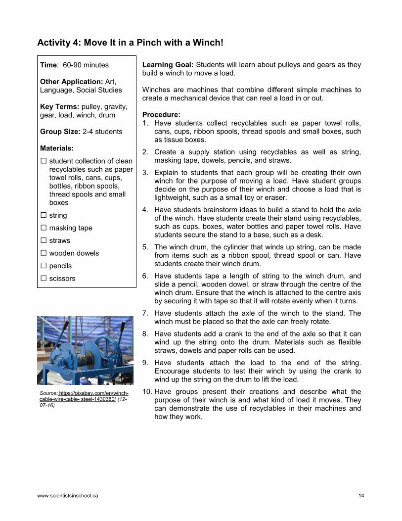
Source: https://pixabay.com/en/winch-cable-wire-cable- steel-1430380/ (12-07-16)
www.scientistsinschool.ca 15
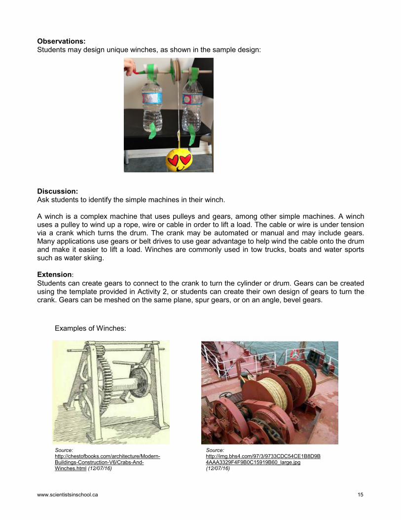
Observations: Students may design unique winches, as shown in the sample design: Discussion: Ask students to identify the simple machines in their winch. A winch is a complex machine that uses pulleys and gears, among other simple machines. A winch uses a pulley to wind up a rope, wire or cable in order to lift a load. The cable or wire is under tension via a crank which turns the drum. The crank may be automated or manual and may include gears. Many applications use gears or belt drives to use gear advantage to help wind the cable onto the drum and make it easier to lift a load. Winches are commonly used in tow trucks, boats and water sports such as water skiing. Extension: Students can create gears to connect to the crank to turn the cylinder or drum. Gears can be created using the template provided in Activity 2, or students can create their own design of gears to turn the crank. Gears can be meshed on the same plane, spur gears, or on an angle, bevel gears.
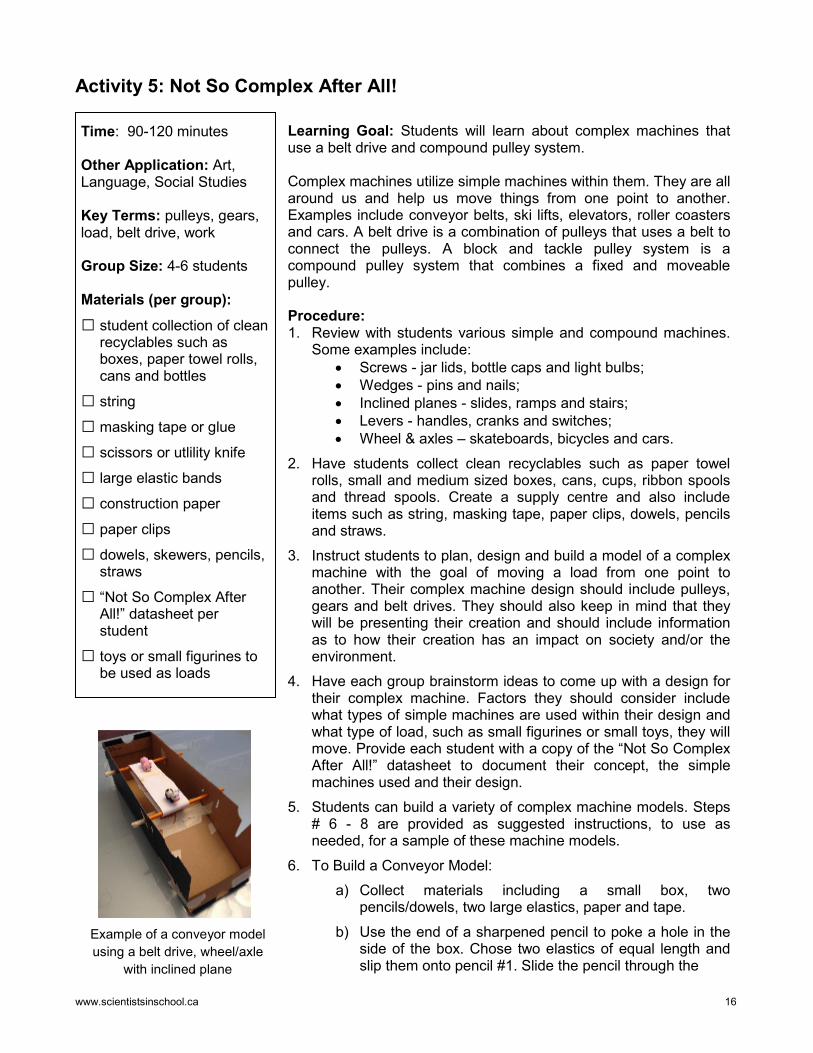
Source: http://chestofbooks.com/architecture/Modern-Buildings-Construction-V6/Crabs-And-Winches.html (12/07/16)
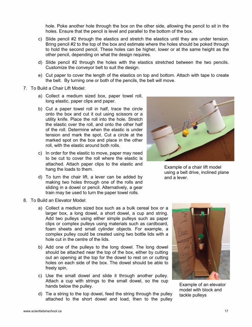
Source: http://img.bhs4.com/97/3/9733CDC54CE1B8D9B4AAA3329F4F9B0C15919B60_large.jpg (12/07/16)
Examples of Winches:
www.scientistsinschool.ca 16
Activity 5: Not So Complex After All!
Time: 90-120 minutes Other Application: Art, Language, Social Studies Key Terms: pulleys, gears, load, belt drive, work Group Size: 4-6 students Materials (per group): □ student collection of clean
recyclables such as boxes, paper towel rolls, cans and bottles
□ string
□ masking tape or glue
□ scissors or utlility knife
□ large elastic bands
□ construction paper
□ paper clips
□ dowels, skewers, pencils, straws
□ “Not So Complex After All!” datasheet per student
□ toys or small figurines to be used as loads
Learning Goal: Students will learn about complex machines that use a belt drive and compound pulley system. Complex machines utilize simple machines within them. They are all around us and help us move things from one point to another. Examples include conveyor belts, ski lifts, elevators, roller coasters and cars. A belt drive is a combination of pulleys that uses a belt to connect the pulleys. A block and tackle pulley system is a compound pulley system that combines a fixed and moveable pulley. Procedure: 1. Review with students various simple and compound machines.
Some examples include: • Screws - jar lids, bottle caps and light bulbs; • Wedges - pins and nails; • Inclined planes - slides, ramps and stairs; • Levers - handles, cranks and switches; • Wheel & axles – skateboards, bicycles and cars.
2. Have students collect clean recyclables such as paper towel rolls, small and medium sized boxes, cans, cups, ribbon spools and thread spools. Create a supply centre and also include items such as string, masking tape, paper clips, dowels, pencils and straws.
3. Instruct students to plan, design and build a model of a complex machine with the goal of moving a load from one point to another. Their complex machine design should include pulleys, gears and belt drives. They should also keep in mind that they will be presenting their creation and should include information as to how their creation has an impact on society and/or the environment.
4. Have each group brainstorm ideas to come up with a design for their complex machine. Factors they should consider include what types of simple machines are used within their design and what type of load, such as small figurines or small toys, they will move. Provide each student with a copy of the “Not So Complex After All!” datasheet to document their concept, the simple machines used and their design.
5. Students can build a variety of complex machine models. Steps # 6 - 8 are provided as suggested instructions, to use as needed, for a sample of these machine models.
6. To Build a Conveyor Model: a) Collect materials including a small box, two
pencils/dowels, two large elastics, paper and tape. b) Use the end of a sharpened pencil to poke a hole in the
side of the box. Chose two elastics of equal length and slip them onto pencil #1. Slide the pencil through the
Example of a conveyor model using a belt drive, wheel/axle
with inclined plane
www.scientistsinschool.ca 17
Example of a chair lift model using a belt drive, inclined plane and a lever.
Example of an elevator model with block and tackle pulleys
hole. Poke another hole through the box on the other side, allowing the pencil to sit in the holes. Ensure that the pencil is level and parallel to the bottom of the box.
c) Slide pencil #2 through the elastics and stretch the elastics until they are under tension. Bring pencil #2 to the top of the box and estimate where the holes should be poked through to hold the second pencil. These holes can be higher, lower or at the same height as the other pencil, depending on what the design requires.
d) Slide pencil #2 through the holes with the elastics stretched between the two pencils. Customize the conveyor belt to suit the design.
e) Cut paper to cover the length of the elastics on top and bottom. Attach with tape to create the belt. By turning one or both of the pencils, the belt will move.
7. To Build a Chair Lift Model: a) Collect a medium sized box, paper towel roll,
long elastic, paper clips and paper. b) Cut a paper towel roll in half, trace the circle
onto the box and cut it out using scissors or a utility knife. Place the roll into the hole. Stretch the elastic over the roll, and onto the other half of the roll. Determine when the elastic is under tension and mark the spot. Cut a circle at the marked spot on the box and place in the other roll, with the elastic around both rolls.
c) In order for the elastic to move, paper may need to be cut to cover the roll where the elastic is attached. Attach paper clips to the elastic and hang the loads to them.
d) To turn the chair lift, a lever can be added by making two holes through one of the rolls and sliding in a dowel or pencil. Alternatively, a gear train may be used to turn the paper towel rolls.
8. To Build an Elevator Model: a) Collect a medium sized box such as a bulk cereal box or a
larger box, a long dowel, a short dowel, a cup and string. Add two pulleys using either simple pulleys such as paper clips or complex pulleys using materials such as cardboard, foam sheets and small cylinder objects. For example, a complex pulley could be created using two bottle lids with a hole cut in the centre of the lids.
b) Add one of the pulleys to the long dowel. The long dowel should be attached near the top of the box, either by cutting out an opening at the top for the dowel to rest on or cutting holes on each side of the box. The dowel should be able to freely spin.
c) Use the small dowel and slide it through another pulley. Attach a cup with strings to the small dowel, so the cup hands below the pulley.
d) Tie a string to the top dowel, feed the string through the pulley attached to the short dowel and load, then to the pulley
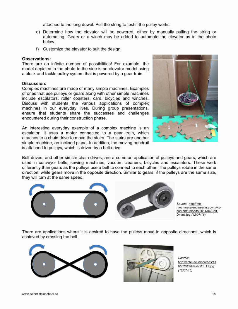
www.scientistsinschool.ca 18
attached to the long dowel. Pull the string to test if the pulley works. e) Determine how the elevator will be powered, either by manually pulling the string or
automating. Gears or a winch may be added to automate the elevator as in the photo below.
f) Customize the elevator to suit the design.
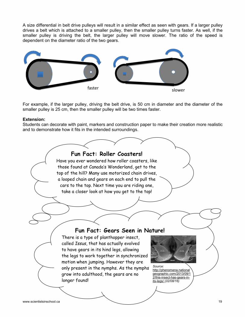
Observations: There are an infinite number of possibilities! For example, the model depicted in the photo to the side is an elevator model using a block and tackle pulley system that is powered by a gear train. Discussion: Complex machines are made of many simple machines. Examples of ones that use pulleys or gears along with other simple machines include escalators, roller coasters, cars, bicycles and winches. Discuss with students the various applications of complex machines in our everyday lives. During group presentations, ensure that students share the successes and challenges encountered during their construction phase. An interesting everyday example of a complex machine is an escalator. It uses a motor connected to a gear train, which attaches to a chain drive to move the stairs. The stairs are another simple machine, an inclined plane. In addition, the moving handrail is attached to pulleys, which is driven by a belt drive. Belt drives, and other similar chain drives, are a common application of pulleys and gears, which are used in conveyor belts, sewing machines, vacuum cleaners, bicycles and escalators. These work differently than gears as the pulleys use a belt to connect to each other. The pulleys rotate in the same direction, while gears move in the opposite direction. Similar to gears, if the pulleys are the same size, they will turn at the same speed.
There are applications where it is desired to have the pulleys move in opposite directions, which is achieved by crossing the belt.
Source: http://nptel.ac.in/courses/116102012/Flash/M1_11.jpg (12/07/16)
Source: http://me-mechanicalengineering.com/wp-content/uploads/2014/06/Belt-Drives.jpg (12/07/16)
www.scientistsinschool.ca 19
A size differential in belt drive pulleys will result in a similar effect as seen with gears. If a larger pulley drives a belt which is attached to a smaller pulley, then the smaller pulley turns faster. As well, if the smaller pulley is driving the belt, the larger pulley will move slower. The ratio of the speed is dependent on the diameter ratio of the two gears.
For example, if the larger pulley, driving the belt drive, is 50 cm in diameter and the diameter of the smaller pulley is 25 cm, then the smaller pulley will be two times faster. Extension: Students can decorate with paint, markers and construction paper to make their creation more realistic and to demonstrate how it fits in the intended surroundings.
faster
slower
Fun Fact: Roller Coasters! Have you ever wondered how roller coasters, like those found at Canada’s Wonderland, get to the top of the hill? Many use motorized chain drives, a looped chain and gears on each end to pull the cars to the top. Next time you are riding one, take a closer look at how you get to the top!
Fun Fact: Gears Seen in Nature! There is a type of planthopper insect, called Issus, that has actually evolved to have gears in its hind legs, allowing the legs to work together in synchronized motion when jumping. However they are only present in the nymphs. As the nymphs grow into adulthood, the gears are no longer found!
Source: http://phenomena.nationalgeographic.com/2013/09/12/this-insect-has-gears-in-its-legs/ (02/08/16)
www.scientistsinschool.ca 20
Name:____________________
Not So Complex After All!
Purpose of Complex Machine: Simple and Compound Machines Used: Pulley Block and Tackle Pulley Belt drive Screw Wedge Inclined plane Gear Lever Wheel & Axle Draw your design:
www.scientistsinschool.ca 21
Teacher Resources Literary Resources Experiments with Simple Machines. Salvatore Tocci. 2003. Children’s Press. ISBN 0-516-22604-5 Provides step-by-step procedures demonstrating use of simple machines. Science Experiments: Lever, Wheels, Pulleys. John Farndon. 2002. Benchmark Books. ISBN 0-71614-1341-3. Explanation and experiments for gears, pulleys and belt drives. Simple Machines: Pulleys & Gears. David Glover. 2006. Heinemann Library. ISBN 1-4034-8564-X Website Resources https://woodgears.ca/gear_cutting/template.html (08/07/2016) Template maker for gears. http://www.sciencebuddies.org/science-fair-projects/project_ideas/ApMech_p016.shtml#background (08/07/2016) Description of gears and gear ratios. http://cstmuseum.techno-science.ca/en/education/tell-me-about-background-information-for-simple-machines.php#family (08/07/2016) Overview of simple machines – Canada Science and Technology museum. https://www.teachengineering.org/lessons/view/umo_challenges_lesson02 (08/07/2016) Full description of gears, bicycles, ratios, lessons and worksheets. https://www.teachengineering.org/lessons/view/cub_simple_lesson05 (08/07/2016) Full description on pulleys and different types of pulleys. https://www.exploratorium.edu/cycling/gears1.html (08/07/2016) A neat bicycle experiment. http://zipline.wvu.edu/ (08/07/2016) West Virginia University on science behind zip lines. http://www.sciencebuddies.org/science-fair-projects/project_ideas/Phys_p100.shtml#background (08/07/2016) Building a ski lift using pulleys. http://www.dkfindout.com/uk/science/simple-machines/gears/ (08/07/2016) Describes gear sizes, force vs speed. Interactive Whiteboard Resources “Wheels & Gears” http://exchange.smarttech.com/details.html?id=933753b3-98da-4033-a89a-d6339a33ca5d (08/07/2016) Lesson on gears, gear ratios, direction and speed. “Wheels, Gears” http://exchange.smarttech.com/details.html?id=4cb37b25-fb67-4f13-8704-0baf75720a4e (08/07/2016) Collection of images of gears and wheels. Multi-media https://www.brainpop.com/technology/simplemachines/gears/ 3:41 min (08/07/2016) Video on gears
www.scientistsinschool.ca 22
http://pbskids.org/video/?guid=da901391-4f4f-4ac1-8442-6e027ed4b65d 1:36 min (08/07/2016) PBS video describing how pulleys work http://pbskids.org/video/?guid=9a6a8dca-c3e8-4429-aab6-e778f3039c7a 2:38 min (08/07/2016) PBS video showing how bicycles use gears to help ride https://www.youtube.com/watch?v=LiBcur1aqcg&feature=youtu.be 1:33 min (08/07/2016) Video on pulleys by Mocomi Kids http://www.sciencekids.co.nz/videos/physics/gears.html 10:58 min (02/08/16) Comprehensive video on gear basics. Student Resources Literary Resources Pulleys. Anne Welsbacher. 2001. Bridgestone Books. ISBN 0-7368-0612-1 Overview of pulleys, parts, types and uses in complex machines. Pulleys to the rescue. Sharon Thales. 2007. Capstone Press. ISBN 978-0-7368-6748-1 Types of pulleys and their uses. Gear Up! Keith Good. 2003. Lerner Publishing Group. ISBN 978-0822535669 Explanation of projects using gears. Pulleys and Gears. Angela Royston. 2001. Heinemann Library. ISBN 1-57572-320-4 Description of pulleys, gears, belt drives, and their uses. Making Machines with Pulleys. Chris Oxlade. 2015. Heinemann Raintree. ISBN 978-1-4109-6800-5 Details on history of pulleys, complex machines and experiments. Pulleys. Sally W. Walker. Roseann Feldmann. 2002. Lerners Publications Company. ISBN 0-8225-2220-9. Reviews concepts of gravity, forces, work, friction and how pulleys work. Science Matters: Pulleys. James De Madeiros. 2010. Weigl Publishing. ISBN 978-1-60596-041-8 Covers history of pulleys, concepts of friction and advantages with pulleys. Interactive Resources http://www.smart-kit.com/s5042/connect-it-gear-game/ (02/08/16) Interactive game to illustrate use of gears and gear trains. References In addition to resources listed above, the following websites were also used to develop this package: http://help.ziplinegear.com/entries/26571257-Zip-Line-Trolleys (25/07/16).

Get kids excited about science
Science Education Through Partnership Scientists in School is a leading science education charity that reaches more Kindergarten to Grade 8 youth than any other science non-profit in Canada – 670,000 in the 2016-17 school year. Through our hands-on, inquiry-based science, technology, engineering, math (STEM) and environmental classroom and community workshops, we strive to ignite scientific curiosity in children so that they question intelligently; learn through discovery; connect scientific knowledge to their world; get excited about science, technology, engineering and math; and have their interest in careers in those fields piqued. By making science a verb - something you do - our workshops allow children’s natural curiosity to reign, inspire kids to see themselves as scientists and engineers, and make connections between science and the world around them. This sets the stage for a scientifically-literate future generation who will fuel Canada’s economic prosperity and think critically about the scientific challenges facing our society. Scientists in School relies upon corporate, community, government and individual donors, as well as school board partners for support to develop new programs, continuously improve our existing programs, reach new geographic areas, provide complimentary workshops to less-privileged schools, and subsidize the cost of every one of our 24,800 annual classroom workshops.
Our Partners Catalyst Level:
Natural Sciences and Engineering Research Council (NSERC), TD Friends of the Environment Foundation, Toronto Pearson International Airport
Innovation Level:
Google Canada, John and Deborah Harris Family Foundation, Nuclear Waste Management Organization, RBC Foundation
Imagination Level:
Amgen Canada, Amgen Foundation, McMillan LLP, Ontario Power Generation Superior Glove Works Ltd., TELUS
Discovery Level:
Cameco, Celestica, Community Foundation of Ottawa, J.P. Bickell Foundation Isherwood Associates, MilliporeSigma, Purdue Pharma, Syngenta, Systematix Inc., The J.W. McConnell Family Foundation,
The Maurice Price Foundation, The McLean Foundation
Exploration Level: Ajax Community Fund at Durham Community Foundation, Consulting Engineers of Ontario, Huronia
Community Foundation Isherwood Associates, Lee Valley Tools, Meridian Credit Union, Rotary Club of Lethbridge, Siemens Milltronics Process Instruments,
The Optimist Club of Ajax, Veridian Connections, Whitby Mayor’s Community Development Fund
[email protected] – www.scientistsinschool.ca Scientists in School is a registered Canadian charity: #867139537RR0001