Embed Size (px)
Citation preview
INSTALLATION MANUAL
KR300 - KR302 - KR310 - KR312KR510 - KR512
GEARMOTOR FOR SWING GATES
FA00290-EN
EnglishEN
p. 2
- M
anual
cod
e: F
A0
02
90
-EN
FA
00
29
0-E
N v
. 1
- 11
/2015
- ©
Cam
e S
.p.A
. Th
e co
nten
ts o
f th
is m
anual
may
be
chan
ged
at
any
time
with
out
prio
r not
ice.
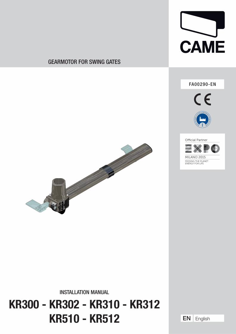
Danger of hand crushing
Danger! High voltage.
No transiting while the barrier is moving
Danger of foot crushing
WARNING!important safety instructions for people:
READ CAREFULLY!
PREMISE
• THIS PRODUCT SHOULD ONLY BE USED FOR THE PURPOSE FOR WHICH IT WAS EXPLICITLY DESIGNED. ANY OTHER USE IS DANGEROUS. CAME S.P.A. IS NOT LIABLE FOR ANY DAMAGE CAUSED BYIMPROPER, WRONGFUL AND UNREASONABLE USE • KEEP THESE WARNINGS TOGETHER WITH THE INSTALLATION AND OPERATION MANUALS THAT COME WITH THE OPERATOR.
BEFORE INSTALLING
(CHECKING WHAT'S THERE: IF SOMETHING IS MISSING, DO NOT CONTINUE UNTIL YOU HAVE COMPLIED WITH ALL SAFETY PROVISIONS)
• CHECK THAT THE AUTOMATED PARTS ARE IN PROPER MECHANICAL ORDER, THAT THE OPERATOR IS LEVEL AND ALIGNED, AND THAT IT OPENS AND CLOSES PROPERLY. MAKE SURE YOU HAVE SUITABLE MECHANICAL STOPS • IF THE OPERATOR IS TO BE INSTALLED AT A HEIGHT OF LESS THAN 2.5 M FROM THE GROUND OR OTHER ACCESS LEVEL, MAKE SURE YOU HAVE ANY NECESSARY PROTECTIONS AND/OR WARNINGS IN PLACE • IF ANY PEDESTRIAN OPENINGS ARE FITTED INTO THE OPERATOR, THERE MUST ALSO BE A A SYSTEM TO BLOCK THEIR OPENING WHILE THEY ARE MOVING • MAKE SURE THAT THE OPENING AUTOMATED DOOR OR GATE CANNOT ENTRAP PEOPLE AGAINST THE FIXED PARTS OF THE OPERATOR • DO NOT FIT UPSIDE DOWN OR ONTO ELEMENTS THAT COULD BEND. IF NECESSARY, ADD SUITABLE REINFORCEMENTS TO THE ANCHORING POINTS • DO NOT INSTALL DOOR OR GATE LEAVES ON TILTED SURFACES • MAKE SURE ANY SPRINKLER SYSTEMS CANNOT WET THE OPERATOR FROM THE GROUND UP • MAKE SURE THE TEMPERATURE RANGE SHOWN ON THE PRODUCT LITERATURE IS SUITABLE TO THE CLIMATE WHERE IT WILL BE INSTALLED • FOLLOW ALL INSTRUCTIONS AS IMPROPER INSTALLATION MAY RESULT IN SERIOUS BODILY INJURY • IT IS IMPORTANT TO FOLLOW THESE INSTRUCTIONS FOR THE SAFETY OF PEOPLE. KEEP THESE INSTRUCTIONS.
INSTALLING
• SUITABLY SECTION OFF AND DEMARCATE THE ENTIRE INSTALLATION SITE TO PREVENT UNAUTHORIZED PERSONS FROM ENTERING THE AREA, ESPECIALLY MINORS AND CHILDREN • BE CAREFUL WHEN HANDLING OPERATORS THAT WEIGH OVER 20 KG. IF NEED BE, USE PROPER SAFETY HOISTING EQUIPMENT • ALL OPENING COMMANDS (THAT IS, BUTTONS, KEY SWITCHES, MAGNETIC READERS, AND SO ON) MUST BE INSTALLED AT LEAST 1.85 M FROM THE PERIMETER OF THE GATE'S WORKING AREA, OR WHERE THEY CANNOT BE REACHED FROM OUTSIDE THE GATE. ALSO, ANY DIRECT COMMANDS (WHETHER BUTTONS, TOUCH PANELS, AND SO ON) MUST BE INSTALLED AT LEAST 1.5 M FROM THE GROUND AND MUST NOT BE REACHABLE BY UNAUTHORIZED PERSONS • ALL MAINTAINED ACTION COMMANDS, MUST BE FITTED IN PLACES FROM WHICH THE MOVING GATE LEAVES AND TRANSIT AND DRIVING AREAS ARE VISIBLE • APPLY, IF MISSING, A PERMANENT SIGN SHOWING THE POSITION OF THE RELEASE DEVICE • BEFORE DELIVERING TO THE USERS, MAKE SURE THE SYSTEM IS EN 12453 STANDARD COMPLIANT (REGARDING IMPACT FORCES), AND ALSO MAKE SURE THE SYSTEM HAS BEEN PROPERLY ADJUSTED AND THAT ANY SAFETY, PROTECTION AND MANUAL RELEASE DEVICES ARE WORKING PROPERLY • APPLY WARNING SIGNS WHERE NECESSARY AND IN A VISIBLE PLACE, (SUCH AS, SUCH AS THE GATE'S PLATE
SPECIAL USER-INSTRUCTIONS AND RECOMMENDATIONS
• KEEP GATE OPERATION AREAS CLEAN AND FREE OF ANY OBSTRUCTIONS. MAKE SURE THAT THE PHOTOCELLS ARE FREE OF ANY OVERGROWN VEGETATION AND THAT THE OPERATOR'S AREA OF OPERATION IS FREE OF ANY OBSTRUCTIONS • DO NOT ALLOW CHILDREN TO PLAY WITH FIXED COMMANDS, OR TO LOITER IN THE GATE'S MANEUVERING AREA. KEEP ANY REMOTE CONTROL TRANSMITTERS OR ANY OTHER COMMAND DEVICE AWAY FROM CHILDREN, TO PREVENT THE OPERATOR FROM BEING ACCIDENTALLY ACTIVATED. • THE APPARATUS MAY BE USED BY CHILDREN OF EIGHT YEARS AND ABOVE AND BY PHYSICALLY, MENTALLY AND SENSORY-CHALLENGED PEOPLE, OR EVEN ONES WITHOUT ANY EXPERIENCE, PROVIDED THIS HAPPENS UNDER CLOSE SUPERVISION OR ONCE THEY HAVE BEEN PROPERLY INSTRUCTED TO USE THE APPARATUS SAFELY AND TO THE POTENTIAL HAZARDS INVOLVED. CHILDREN MUST NOT PLAY WITH THE APPARATUS. CLEANING AND MAINTENANCE BY USERS MUST NOT BE DONE BY CHILDREN, UNLESS PROPERLY SUPERVISED • FREQUENTLY CHECK THE SYSTEM FOR ANY MALFUNCTIONS OR SIGNS OF WEAR AND TEAR OR DAMAGE TO THE MOVING STRUCTURES, TO THE COMPONENT PARTS, ALL ANCHORING POINTS, INCLUDING CABLES AND ANY ACCESSIBLE CONNECTIONS. KEEP ANY HINGES, MOVING JOINTS AND SLIDE RAILS PROPERLY LUBRICATED • PERFORM FUNCTIONAL CHECKS ON THE PHOTOCELLS AND SENSITIVE SAFETY EDGES, EVERY SIX MONTHS. TO CHECK WHETHER THE PHOTOCELLS ARE WORKING, WAVE AN OBJECT IN FRONT OF THEM WHILE THE GATE IS CLOSING; IF THE OPERATOR INVERTS ITS DIRECTION OF TRAVEL OR SUDDENLY
STOPS, THE PHOTOCELLS ARE WORKING PROPERLY. THIS IS THE ONLY MAINTENANCE OPERATION TO DO WITH THE POWER ON. CONSTANTLY CLEAN THE PHOTOCELLS' GLASS COVERS USING A SLIGHTLY WATER-MOISTENED CLOTH; DO NOT USE SOLVENTS OR OTHER CHEMICAL PRODUCTS THAT MAY RUIN THE DEVICES • IF REPAIRS OR MODIFICATIONS ARE REQUIRED TO THE SYSTEM, RELEASE THE OPERATOR AND DO NOT USE IT UNTIL SAFETY CONDITIONS HAVE BEEN RESTORED • CUT OFF THE POWER SUPPLY BEFORE RELEASING THE OPERATOR FOR MANUAL OPENINGS AND BEFORE ANY OTHER OPERATION, TO PREVENT POTENTIALLY HAZARDOUS SITUATIONS. READ THE INSTRUCTIONS IF THE POWER SUPPLY CABLE IS DAMAGED, IT MUST BE REPLACED BY THE MANUFACTURER OR AUTHORIZED TECHNICAL ASSISTANCE SERVICE, OR IN ANY CASE, BY SIMILARLY QUALIFIED PERSONS, TO PREVENT ANY RISK • IT IS FORBIDDEN FOR USERS TO PERFORM ANY OPERATIONS THAT ARE NOT EXPRESSLY REQUIRED OF THEM AND WHICH ARE NOT LISTED IN THE MANUALS. FOR ANY REPAIRS, MODIFICATIONS / ADJUSTMENTS, AND FOR EXTRA-ORDINARY MAINTENANCE, CALL TECHNICAL ASSISTANCE • LOG THE JOB AND CHECKS INTO THE PERIODIC MAINTENANCE LOG.
FURTHER RECOMMENDATIONS FOR ALL
•KEEP CLEAR OF HINGES AND MECHANICAL MOVING PARTS • DO NOT ENTER THE OPERATOR'S AREA OF OPERATION WHEN IT IS MOVING • DO NOT COUNTER THE OPERATOR'S MOVEMENT AS THIS COULD RESULT IN DANGEROUS SITUATIONS • ALWAYS PAY SPECIAL ATTENTION TO ANY DANGEROUS POINTS, WHICH HAVE TO BE LABELED WITH SPECIFIC PICTOGRAMS AND/OR BLACK AND YELLOW STRIPES • WHILE USING A SELECTOR SWITCH OR A COMMAND IN MAINTAINED ACTIONS, KEEP CHECKING THAT THERE ARE NO PERSONS WITHIN THE OPERATING RANGE OF ANY MOVING PARTS, UNTIL THE COMMAND IS RELEASED • THE GATE MAY MOVE AT ANY TIME AND WITHOUT WARNING • ALWAYS CUT OFF THE MAINS POWER SUPPLY BEFORE PERFORMING ANY MAINTENANCE OR CLEANING.
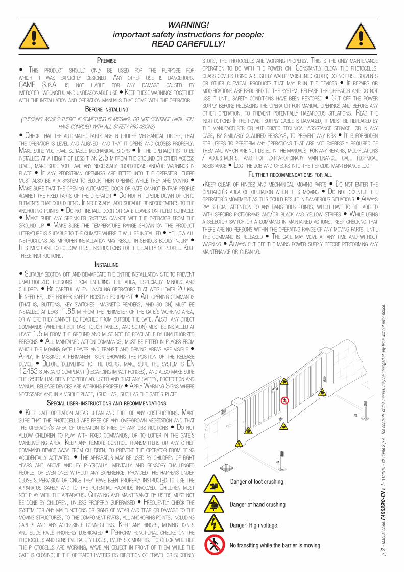
0
200
400
600
800
1000
1200
2 2,5 3 3,5 4 4,5 5 5,25
KR510 - KR512
KR300 - KR302 - KR310 - KR312
p. 3
- M
anual
cod
e: F
A0
02
90
-EN
FA
00
29
0-E
N v
. 1
- 11
/2015
- ©
Cam
e S
.p.A
. Th
e co
nten
ts o
f th
is m
anual
may
be
chan
ged
at
any
time
with
out
prio
r not
ice.
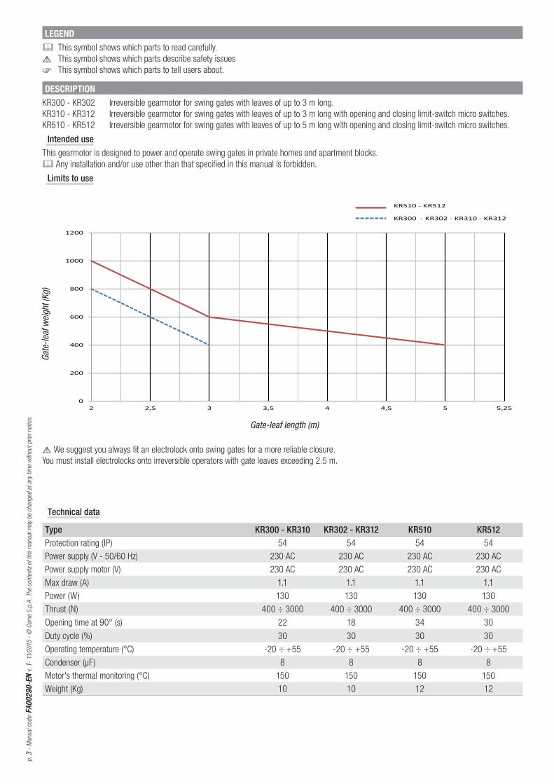
Technical data
Type KR300 - KR310 KR302 - KR312 KR510 KR512Protection rating (IP) 54 54 54 54
Power supply (V - 50/60 Hz) 230 AC 230 AC 230 AC 230 AC
Power supply motor (V) 230 AC 230 AC 230 AC 230 AC
Max draw (A) 1.1 1.1 1.1 1.1
Power (W) 130 130 130 130
Thrust (N) 400 ÷ 3000 400 ÷ 3000 400 ÷ 3000 400 ÷ 3000
Opening time at 90° (s) 22 18 34 30
Duty cycle (%) 30 30 30 30
Operating temperature (°C) -20 ÷ +55 -20 ÷ +55 -20 ÷ +55 -20 ÷ +55
Condenser (μF) 8 8 8 8
Motor's thermal monitoring (°C) 150 150 150 150
Weight (Kg) 10 10 12 12
DESCRIPTIONKR300 - KR302 Irreversible gearmotor for swing gates with leaves of up to 3 m long.
KR310 - KR312 Irreversible gearmotor for swing gates with leaves of up to 3 m long with opening and closing limit-switch micro switches.
KR510 - KR512 Irreversible gearmotor for swing gates with leaves of up to 5 m long with opening and closing limit-switch micro switches.
Intended useThis gearmotor is designed to power and operate swing gates in private homes and apartment blocks.
Any installation and/or use other than that specifi ed in this manual is forbidden.
Limits to use
LEGENDThis symbol shows which parts to read carefully.
⚠ This symbol shows which parts describe safety issues
☞ This symbol shows which parts to tell users about.
Gate-
leaf w
eight
(Kg)
Gate-leaf length (m)
⚠ We suggest you always fi t an electrolock onto swing gates for a more reliable closure.
You must install electrolocks onto irreversible operators with gate leaves exceeding 2.5 m.
11323
4956 * - 1356 **
304 * - 504 **
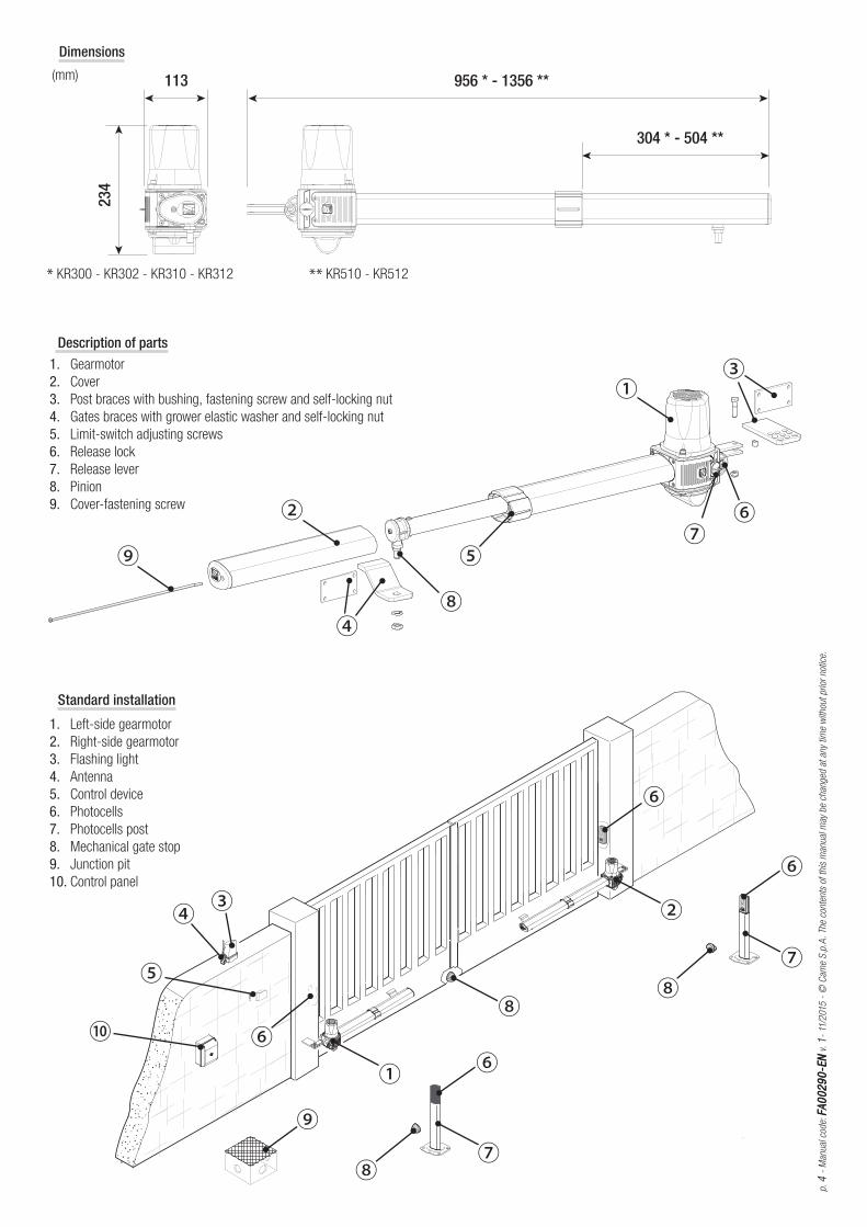
* KR300 - KR302 - KR310 - KR312 ** KR510 - KR512
p. 4
- M
anual
cod
e: F
A0
02
90
-EN
FA
00
29
0-E
N v
. 1
- 11
/2015
- ©
Cam
e S
.p.A
. Th
e co
nten
ts o
f th
is m
anual
may
be
chan
ged
at
any
time
with
out
prio
r not
ice.
Standard installation
1. Left-side gearmotor
2. Right-side gearmotor
3. Flashing light
4. Antenna
5. Control device
6. Photocells
7. Photocells post
8. Mechanical gate stop
9. Junction pit
10. Control panel
Description of parts1. Gearmotor
2. Cover
3. Post braces with bushing, fastening screw and self-locking nut
4. Gates braces with grower elastic washer and self-locking nut
5. Limit-switch adjusting screws
6. Release lock
7. Release lever
8. Pinion
9. Cover-fastening screw
Dimensions
(mm)
p. 5
- M
anual
cod
e: F
A0
02
90
-EN
FA
00
29
0-E
N v
. 1
- 11
/2015
- ©
Cam
e S
.p.A
. Th
e co
nten
ts o
f th
is m
anual
may
be
chan
ged
at
any
time
with
out
prio
r not
ice.
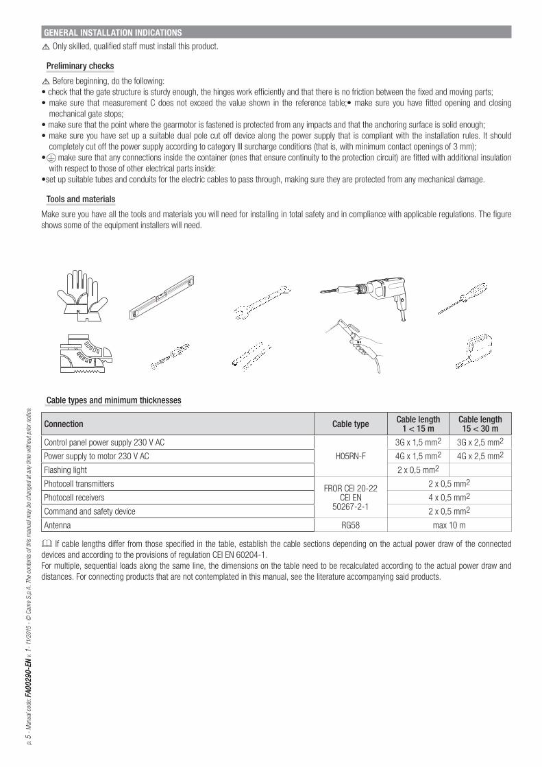
GENERAL INSTALLATION INDICATIONS
⚠ Only skilled, qualified staff must install this product.
Preliminary checks
⚠ Before beginning, do the following:
• check that the gate structure is sturdy enough, the hinges work efficiently and that there is no friction between the fixed and moving parts;
• make sure that measurement C does not exceed the value shown in the reference table;• make sure you have fitted opening and closing
mechanical gate stops;
• make sure that the point where the gearmotor is fastened is protected from any impacts and that the anchoring surface is solid enough;
• make sure you have set up a suitable dual pole cut off device along the power supply that is compliant with the installation rules. It should
completely cut off the power supply according to category III surcharge conditions (that is, with minimum contact openings of 3 mm);
• make sure that any connections inside the container (ones that ensure continuity to the protection circuit) are fitted with additional insulation
with respect to those of other electrical parts inside:
•set up suitable tubes and conduits for the electric cables to pass through, making sure they are protected from any mechanical damage.
Tools and materials
Make sure you have all the tools and materials you will need for installing in total safety and in compliance with applicable regulations. The figure
shows some of the equipment installers will need.
Cable types and minimum thicknesses
Connection Cable type Cable length1 < 15 m
Cable length15 < 30 m
Control panel power supply 230 V AC
H05RN-F
3G x 1,5 mm2 3G x 2,5 mm2
Power supply to motor 230 V AC 4G x 1,5 mm2 4G x 2,5 mm2
Flashing light 2 x 0,5 mm2
Photocell transmittersFROR CEI 20-22
CEI EN 50267-2-1
2 x 0,5 mm2
Photocell receivers 4 x 0,5 mm2
Command and safety device 2 x 0,5 mm2
Antenna RG58 max 10 m
If cable lengths diff er from those specifi ed in the table, establish the cable sections depending on the actual power draw of the connected
devices and according to the provisions of regulation CEI EN 60204-1.
For multiple, sequential loads along the same line, the dimensions on the table need to be recalculated according to the actual power draw and
distances. For connecting products that are not contemplated in this manual, see the literature accompanying said products.
Ep.
6 -
Man
ual
cod
e: F
A0
02
90
-EN
FA
00
29
0-E
N v
. 1
- 11
/2015
- ©
Cam
e S
.p.A
. Th
e co
nten
ts o
f th
is m
anual
may
be
chan
ged
at
any
time
with
out
prio
r not
ice.
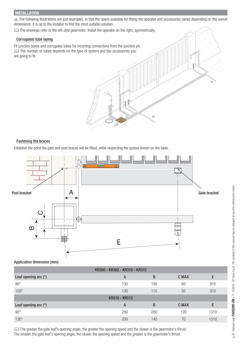
Fastening the braces
Establish the point the gate and post braces will be fitted, while respecting the quotas shown on the table.
The greater the gate leaf's opening angle, the greater the opening speed and the slower is the gearmotor's thrust.
The smaller the gate leaf's opening angle, the slower the opening speed and the greater is the gearmotor's thrust.
Application dimension (mm)
KR300 - KR302 - KR310 - KR312
Leaf opening arc (°) A B C MAX E
90° 130 130 60 910
120° 130 110 50 910
KR510 - KR512
Leaf opening arc (°) A B C MAX E
90° 200 200 120 1310
130° 200 140 70 1310
INSTALLATION
⚠ The following illustrations are just examples, in that the space available for fitting the operator and accessories varies depending on the overall
dimensions. It is up to the installer to find the most suitable solution.
The drawings refer to the left-side gearmotor. Install the operator on the right, symmetrically.
Corrugated tube laying
Fit junction boxes and corrugates tubes for incoming connections from the junction pit.
The number of tubes depends on the type of system and the accessories you
are going to fit.
Gate bracketPost bracket
p. 7
- M
anual
cod
e: F
A0
02
90
-EN
FA
00
29
0-E
N v
. 1
- 11
/2015
- ©
Cam
e S
.p.A
. Th
e co
nten
ts o
f th
is m
anual
may
be
chan
ged
at
any
time
with
out
prio
r not
ice.
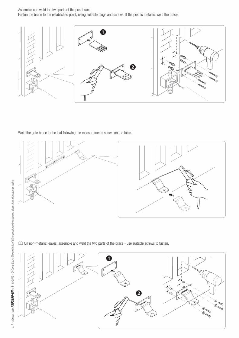
Assemble and weld the two parts of the post brace.
Fasten the brace to the established point, using suitable plugs and screws. If the post is metallic, weld the brace.
Weld the gate brace to the leaf following the measurements shown on the table.
On non-metallic leaves, assemble and weld the two parts of the brace - use suitable screws to fasten.

W V U W V U
ZA3N - ZA3P
A B
p. 8
- M
anual
cod
e: F
A0
02
90
-EN
FA
00
29
0-E
N v
. 1
- 11
/2015
- ©
Cam
e S
.p.A
. Th
e co
nten
ts o
f th
is m
anual
may
be
chan
ged
at
any
time
with
out
prio
r not
ice.
Open the leaf, fit the pinion into the gate brace and fasten it using the supplied washer and nut.
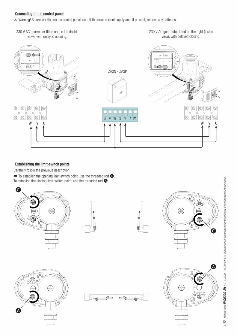
Connecting to the control panel
⚠ Warning! Before working on the control panel, cut off the main current supply and, if present, remove any batteries.
Fastening the gearmotor
Lubricate the bushing A and fit into one of the post brace holes (the holes on the brace are for varying the gate's opening angle.
Fasten the joint B to the post brace using the bolt and nut.
230 V AC gearmotor fi tted on the left (inside
view), with delayed opening.
230 V AC gearmotor fi tted on the right (inside
view), with delayed closing.
C
C
M M
p. 9
- M
anual
cod
e: F
A0
02
90
-EN
FA
00
29
0-E
N v
. 1
- 11
/2015
- ©
Cam
e S
.p.A
. Th
e co
nten
ts o
f th
is m
anual
may
be
chan
ged
at
any
time
with
out
prio
r not
ice.
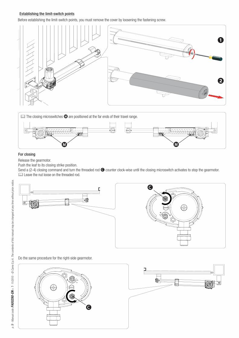
Establishing the limit-switch points
Before establishing the limit-switch points, you must remove the cover by loosening the fastening screw.
For closingRelease the gearmotor.
Push the leaf to its closing strike position.
Send a (2-4) closing command and turn the threaded rod C counter clock-wise until the closing microswitch activates to stop the gearmotor.
Leave the nut loose on the threaded rod.
Do the same procedure for the right-side gearmotor.
The closing microswitches M are positioned at the far ends of their travel range.
A
A
A
B
p. 1
01
0 -
Man
ual
cod
e: F
A0
02
90
-EN
FA
00
29
0-E
N v
. 1
- 11
/2015
- ©
Cam
e S
.p.A
. Th
e co
nten
ts o
f th
is m
anual
may
be
chan
ged
at
any
time
with
out
prio
r not
ice.
INWARD OPENING CONNECTIONS AND INSTALLING
Fastening the braces
Measure quotas A and B (while respecting the quotas shown on the table) to establish the point where the post brace joined with non-supplied
supplementary brace will be fastened.
Application dimension (mm)
KR300 - KR302 - KR310
Leaf opening arc (°) A B E
90° 130 130 910
KR510 - KR512
Leaf opening arc (°) A B E
90° 200 200 1310
For openingRelease the gearmotor.
Reach the wanted leaf-opening point.
Send a (2-3) opening command and turn the threaded rod A clockwise until the microswitch activates to stop the gearmotor.
Leave the nut loose on the threaded rod.
Do the same procedure for the right-side gearmotor.

E
p. 1
111 -
Man
ual
cod
e: F
A0
02
90
-EN
FA
00
29
0-E
N v
. 1
- 11
/2015
- ©
Cam
e S
.p.A
. Th
e co
nten
ts o
f th
is m
anual
may
be
chan
ged
at
any
time
with
out
prio
r not
ice.
Open the gate to 90°, weld or fasten the gate brace using suitable bolts (while respecting quota E as shown in the table).
Assemble and weld the supplementary brace to the post brace. Fasten the supplementary brace to the post.
Fasten the gearmotor to the braces by using the supplied nuts and bolts.
ZA3N - ZA3P
W V U W V U
C
C
A
A
p. 1
21
2 -
Man
ual
cod
e: F
A0
02
90
-EN
FA
00
29
0-E
N v
. 1
- 11
/2015
- ©
Cam
e S
.p.A
. Th
e co
nten
ts o
f th
is m
anual
may
be
chan
ged
at
any
time
with
out
prio
r not
ice.
Establishing the limit-switch points
Carefully follow the previous description.
➡ To establish the opening limit-switch point, use the threaded rod C.
To establish the closing limit-switch point, use the threaded rod A.
230 V AC gearmotor fi tted on the left (inside
view), with delayed opening.
230 V AC gearmotor fi tted on the right (inside
view), with delayed closing.
Connecting to the control panel
⚠ Warning! Before working on the control panel, cut off the main current supply and, if present, remove any batteries.
90°
90°
p. 1
31
3 -
Man
ual
cod
e: F
A0
02
90
-EN
FA
00
29
0-E
N v
. 1
- 11
/2015
- ©
Cam
e S
.p.A
. Th
e co
nten
ts o
f th
is m
anual
may
be
chan
ged
at
any
time
with
out
prio
r not
ice.
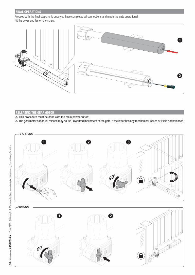
RELEASING
LOCKING
RELEASING THE GEARMOTOR⚠ This procedure must be done with the main power cut off .⚠ The gearmotor's manual release may cause unwanted movement of the gate, if the latter has any mechanical issues or if it is not balanced.
FINAL OPERATIONSProceed with the fi nal steps, only once you have completed all connections and made the gate operational.
Fit the cover and fasten the screw.

p. 1
414
- M
anual
cod
e: F
A0
02
90
-EN
FA
00
29
0-E
N v
. 1
- 11
/2015
- ©
Cam
e S
.p.A
. Th
e co
nten
ts o
f th
is m
anual
may
be
chan
ged
at
any
time
with
out
prio
r not
ice.
MAINTENANCE
Periodic maintenance
☞ Before doing any maintenance, cut off the power supply, to prevent any hazardous situations caused by accidentally activating the operator.
Periodic maintenance log kept by users (every six months)
Date Notes Signature
TROUBLESHOOTING
TROUBLES POSSIBLE CAUSES FIXES
It neither opens
nor closes
• Power supply missing
• The gearmotor is stuck
• The transmitter's battery is run down
• The transmitter is broken
• The stop button is either stuck or broken
• The opening/closing button or the key-switch selector is stuck
• Check main power supply
• Lock the gearmotor
• Replace the batteries
• Call for assistance
• Call for assistance
• Call for assistance
The gate opens
but does not close
• The photocells are soiled. • Clean and check that the photocells work
properly. Otherwise call for assistance
p. 1
51
5 -
Man
ual
cod
e: F
A0
02
90
-EN
FA
00
29
0-E
N v
. 1
- 11
/2015
- ©
Cam
e S
.p.A
. Th
e co
nten
ts o
f th
is m
anual
may
be
chan
ged
at
any
time
with
out
prio
r not
ice.
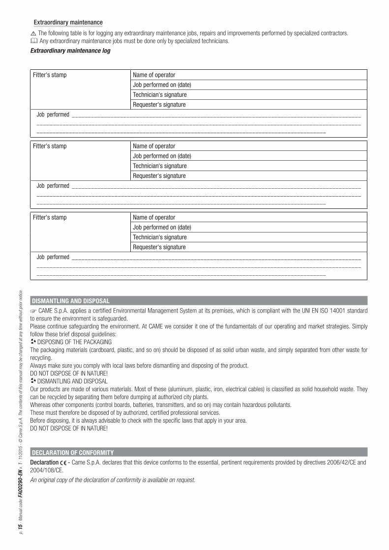
Extraordinary maintenance
⚠ The following table is for logging any extraordinary maintenance jobs, repairs and improvements performed by specialized contractors.
Any extraordinary maintenance jobs must be done only by specialized technicians.
Extraordinary maintenance log
Fitter's stamp Name of operator
Job performed on (date)
Technician's signature
Requester's signature
Job performed ________________________________________________________________________________________________________________________________________________________________________________________________________________________________________________________________________________________
DISMANTLING AND DISPOSAL
☞ CAME S.p.A. applies a certified Environmental Management System at its premises, which is compliant with the UNI EN ISO 14001 standard
to ensure the environment is safeguarded.
Please continue safeguarding the environment. At CAME we consider it one of the fundamentals of our operating and market strategies. Simply
follow these brief disposal guidelines:
DISPOSING OF THE PACKAGING
The packaging materials (cardboard, plastic, and so on) should be disposed of as solid urban waste, and simply separated from other waste for
recycling.
Always make sure you comply with local laws before dismantling and disposing of the product.
DO NOT DISPOSE OF IN NATURE!
DISMANTLING AND DISPOSAL
Our products are made of various materials. Most of these (aluminum, plastic, iron, electrical cables) is classified as solid household waste. They
can be recycled by separating them before dumping at authorized city plants.
Whereas other components (control boards, batteries, transmitters, and so on) may contain hazardous pollutants.
These must therefore be disposed of by authorized, certified professional services.
Before disposing, it is always advisable to check with the specific laws that apply in your area.
DO NOT DISPOSE OF IN NATURE!
DECLARATION OF CONFORMITYDeclaration - Came S.p.A. declares that this device conforms to the essential, pertinent requirements provided by directives 2006/42/CE and
2004/108/CE.
An original copy of the declaration of conformity is available on request.
Fitter's stamp Name of operator
Job performed on (date)
Technician's signature
Requester's signature
Job performed ________________________________________________________________________________________________________________________________________________________________________________________________________________________________________________________________________________________

www. came.comwww. came.com
Came S.p.A.Came S.p.A.
Via Martiri Della Libertà, 15 Via Cornia, 1/b - 1/c
31030 Dosson di CasierDosson di CasierTrevisoTreviso - Italy
33079 Sesto al ReghenaSesto al ReghenaPordenonePordenone - Italy
(+39) 0422 4940 (+39) 0422 4941
(+39) 0434 698111 (+39) 0434 698434
En
glish
En
glish
- M
anual
cod
e: F
A0
02
90
-EN
FA
00
29
0-E
N v
. 1
- 1
1/2
015
- ©
Cam
e S
.p.A
.
The
cont
ents
of
this
man
ual
may
be
chan
ged
at
any
time
with
out
prio
r not
ice.