Embed Size (px)
Citation preview

Gears
Gears are toothed wheels designed to transmit rotary motion and power
from one part of a mechanism to another. They are fitted to shafts with
special devices called keys (or splines) that ensure that the gear and the
shaft rotate together. Gears are used to increase or decrease the output
speed of a mechanism and can also be used to change the direction of
motion of the output.
Simple Gear Train
Gears work by interlocking or meshing
the teeth of the gears together as
shown. When 2 or more gears are
meshed they form a gear train. The
input gear which causes the system to
move is called the driver and the
output gear is called the driven.
The Multiplier Ratio is used to calculate speed, torque and size of gears.
eInputTorqu
ueOutputTorq
InputSpeed
dOutputSpee
Driven
DriverRM ..
Idler Gear
To get the driven gear to rotate in the
same direction as the driver a third gear
is inserted in the system. The idler gear
has no effect on the speed of the
driven gear wheel.

Compound Gear Trains
If gears are required to produce a very large change in speed, for example
100:1 then problems can arise with the size of gear
wheels if a simple gear train is used. The problem can
be overcome by mounting
pairs of gears on the same
shaft as shown.
Ratchet and Pawl
A wheel with saw shaped teeth round its
rim is called a ratchet. The ratchet wheel
usually engages with a tooth shaped lever
called a pawl. The purpose of the pawl is
to allow rotation in one direction only and prevent rotation in the opposite
direction.
Worm and wheel
Another way of making larger speed
reductions is to use a worm and wheel. The
worm, which looks rather like a screw thread, is fixed to the driver shaft
(sometimes directly onto the motor shaft). It meshes with a worm wheel,
which is fixed to the driven shaft. The driven shaft runs at 90’ to the driver
shaft.
You should think of the worm wheel as a gear with only 1 tooth. This allows a
huge reduction in speed which takes up very little space.

Worm and Nut
The worm gear is fixed so that when it
spins, it moves the block. This transmits the
motion through the gear. This allows for a
big change in speed and increased torque
Bevel gears
Bevel gears, like worm wheels, use shafts at 90’
to each other. A whisk which uses bevel gears
to change the direction motion through 90’ as
does the gears in a wind turbine.
Belt Drives
To make rotary motion useful it has to be transmitted from one part of a
machine to another, often with a
change in speed. Connecting too
many gears together can result in
large efficiency losses through
friction.
A simple way of transmitting this motion would be to use a belt wrapped
around 2 pulleys, the belt can be tightened
or tensioned by pulling one of the pulleys out
and locking it in place. The belt should be
angled to give better grip to prevent the belt
from slipping.
Changes in direction can be achieved by crossing over the belts.
An advantage of using a belt drive
is that it allows slippage in machines
where you wouldn’t want for
example a motor to stop or possibly
cease because the belt won’t turn.
Toothed belts
Belt drives tend to use their ability to slip to their advantage, however where
slippage would damage a
mechanism toothed belts have
been developed that retain the
advantages of normal belts but do
not slip.
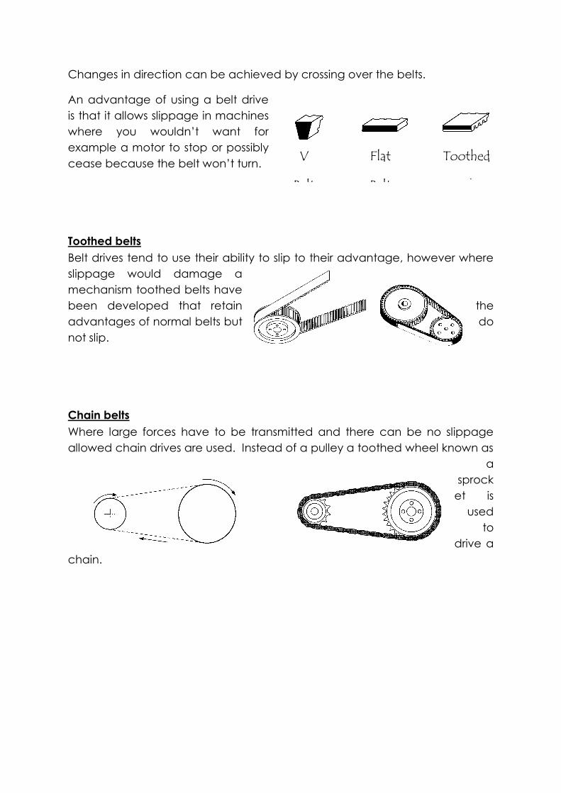
Chain belts
Where large forces have to be transmitted and there can be no slippage
allowed chain drives are used. Instead of a pulley a toothed wheel known as
a
sprock
et is
used
to
drive a
chain.
V
Belt
Flat
Belt
Toothed
Belt

CAMS
A cam is a specifically shaped piece of material, which can be used to
change an input rotary motion to an output motion that is oscillating or
reciprocating.
The cam operates by guiding the motion of a follower held against the cam,
either by its own weight or by a spring. As the cam rotates the follower
moves. The way that it moves and the distance it moves depends on the
cam’s shape and dimensions.
Cam Motion
Pear-shaped cams are often used for controlling valves. For example they
are often used on motor-car cam shafts to operate the engine valves.
A follower controlled by a pear-shaped cam remains
motionless for about half a revolution; during the other
half revolution of the cam the follower rises and falls. As
the pear-shaped cam is symmetrical, the rising motion is
the same as the falling motion. When the follower is not
moving we call this the dwell part of the cam.

In a car engine, cams are fixed on a camshaft. As each cylinder has two
valves, an inlet and an exhaust valve, there are two cams on a camshaft for
each cylinder as shown.
Crank & Slider
Crank & slider mechanisms
involve changes between rotary
and reciprocating motion. The
crank rotates while the slider
reciprocates. The longer the
crank the further the slider will
move.
Reciprocating motion to rotary motion
Car engines use reciprocating pistons,
which are connected to a crankshaft by
connecting rods. As the piston moves up
and down the connecting rods push the
crankshaft round. Each piston moves
down in turn so keeping the crankshaft
turning.
Rotary motion to reciprocating motion
A power hacksaw uses an electric
motor to power a crank, which is
connected to a saw frame. The saw
frame is free to slide on the arm. As the
crank rotates it causes the frame to slide
backwards and forwards on the arm.
The longer the crank the further the saw
frame will move.
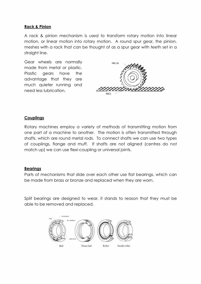
Rack & Pinion
A rack & pinion mechanism is used to transform rotary motion into linear
motion, or linear motion into rotary motion. A round spur gear, the pinion,
meshes with a rack that can be thought of as a spur gear with teeth set in a
straight line.
Gear wheels are normally
made from metal or plastic.
Plastic gears have the
advantage that they are
much quieter running and
need less lubrication.
Couplings
Rotary machines employ a variety of methods of transmitting motion from
one part of a machine to another. The motion is often transmitted through
shafts, which are round metal rods. To connect shafts we can use two types
of couplings, flange and muff. If shafts are not aligned (centres do not
match up) we can use flexi-coupling or universal joints.
Bearings
Parts of mechanisms that slide over each other use flat bearings, which can
be made from brass or bronze and replaced when they are worn.
Split bearings are designed to wear, it stands to reason that they must be
able to be removed and replaced.

Ball and roller bearings change the action of rubbing to that of rolling. These
bearings are used in high speed, high force applications.
Clutches
Clutches are devices that allow two rotating shafts to be connected and
disconnected. There are two types of clutch, the positive clutch and the
friction clutch. A dog clutch is a positive clutch and has four interlocking
block on one shaft that can be interlocked with 4 on the other shaft. A simple
friction clutch relies on two plates to transmit the power from one shaft to
another.
Brakes
There are two main types of brakes disc and drum.
Disk brakes
The main components of a disc brake are:
The brake pads
The caliper, which contains a piston
The rotor, which is mounted to the hub
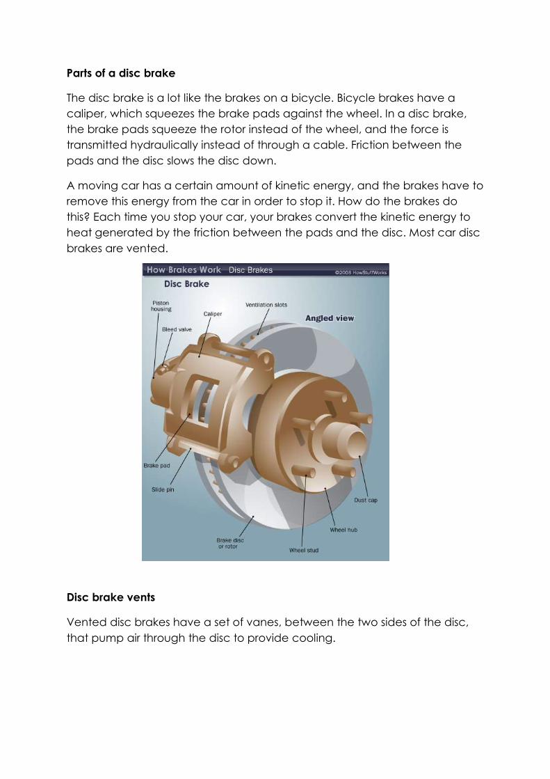
Parts of a disc brake
The disc brake is a lot like the brakes on a bicycle. Bicycle brakes have a
caliper, which squeezes the brake pads against the wheel. In a disc brake,
the brake pads squeeze the rotor instead of the wheel, and the force is
transmitted hydraulically instead of through a cable. Friction between the
pads and the disc slows the disc down.
A moving car has a certain amount of kinetic energy, and the brakes have to
remove this energy from the car in order to stop it. How do the brakes do
this? Each time you stop your car, your brakes convert the kinetic energy to
heat generated by the friction between the pads and the disc. Most car disc
brakes are vented.
Disc brake vents
Vented disc brakes have a set of vanes, between the two sides of the disc,
that pump air through the disc to provide cooling.
Self-Adjusting Brakes
The single-piston floating-caliper disc brake is self-centering and self-
adjusting. The caliper is able to slide from side to side so it will move to the
center each time the brakes are applied. Also, since there is no spring to pull
the pads away from the disc, the pads always stay in light contact with the
rotor (the rubber piston seal and any wobble in the rotor may actually pull
the pads a small distance away from the rotor). This is important because the
pistons in the brakes are much larger in diameter than the ones in the master
cylinder. If the brake pistons retracted into their cylinders, it might take several
applications of the brake pedal to pump enough fluid into the brake cylinder
to engage the brake pads.
Self-adjusting disc brake
Older cars had dual or four-piston fixed-caliper designs. A piston (or two) on
each side of the rotor pushed the pad on that side. This design has been
largely eliminated because single-piston designs are cheaper and more
reliable.
Emergency Brakes
In cars with disc brakes on all four wheels, an emergency brake has to be
actuated by a separate mechanism than the primary brakes in case of a
total primary brake failure. Most cars use a cable to actuate the emergency
brake.
Some cars with four-wheel disc brakes have a separate drum brake
integrated into the hub of the rear wheels. This drum brake is only for the
emergency brake system, and it is actuated only by the cable; it has no
hydraulics.
Other cars have a lever that turns a screw, or actuates a cam, which presses
the piston of the disc brake.

Drum brakes
Drum brakes work on the same principle as disc brakes: Shoes press against a
spinning surface. In this system, that surface is called a drum.
Many cars have drum brakes on the rear wheels and disc brakes on the front.
Drum brakes have more parts than disc brakes and are harder to service, but
they are less expensive to manufacture, and they easily incorporate an
emergency brake mechanism.

Like the disc brake, the drum brake has two brake shoes and a piston. But the
drum brake also has an adjuster mechanism, an emergency brake
mechanism and lots of springs.
When you hit the brake pedal, the piston pushes the brake shoes against the
drum. That's pretty straightforward, but why do we need all of those springs?
This is where it gets a little more complicated. Many drum brakes are self-
actuating. As the brake shoes contact the drum, there is a kind of wedging
action, which has the effect of pressing the shoes into the drum with more
force.
The extra braking force provided by the wedging action allows drum brakes
to use a smaller piston than disc brakes. But, because of the wedging action,
the shoes must be pulled away from the drum when the brakes are released.
This is the reason for some of the springs. Other springs help hold the brake
shoes in place and return the adjuster arm after it actuates.
When you step on your brake pedal the two curved brake shoes, which have
a friction material lining, are forced by hydraulic wheel cylinders against the
inner surface of a rotating brake drum. This contact produces friction causing
the drum and the wheel to slow down or stop.
AB
C
AB
C
D
+ + + +
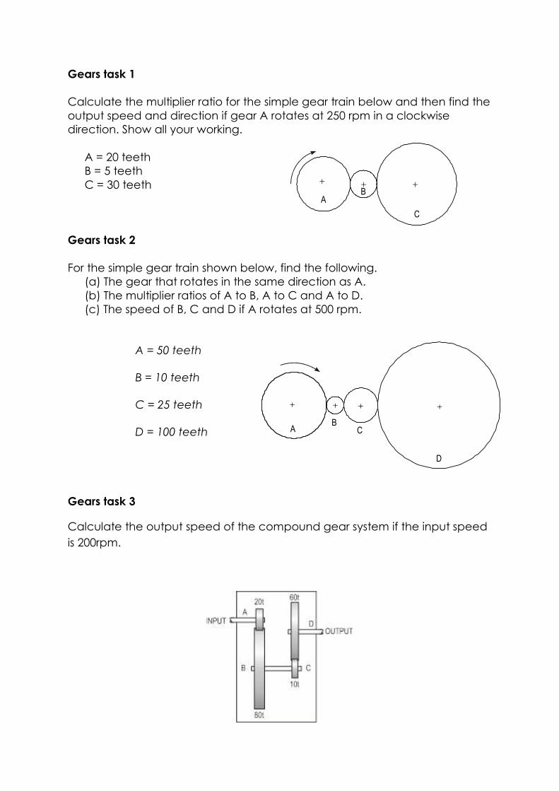
Gears task 1
Calculate the multiplier ratio for the simple gear train below and then find the
output speed and direction if gear A rotates at 250 rpm in a clockwise
direction. Show all your working.
A = 20 teeth
B = 5 teeth
C = 30 teeth
Gears task 2
For the simple gear train shown below, find the following.
(a) The gear that rotates in the same direction as A.
(b) The multiplier ratios of A to B, A to C and A to D.
(c) The speed of B, C and D if A rotates at 500 rpm.
A = 50 teeth
B = 10 teeth
C = 25 teeth
D = 100 teeth
Gears task 3
Calculate the output speed of the compound gear system if the input speed
is 200rpm.

Gears task 4
The compound gear train shown is driven by a motor that runs at 1000 rpm.
Calculate the multiplier ratio of the motor to the output shaft and then the
output speed. Show all your working.
A = 20 teeth
B = 60 teeth
C = 40 teeth
D = 50 teeth
Gears task 5
A motor with a single worm wheel output rotates at 500 rpm. You are given
the following sizes of worm gears from which to select.
(a) = 10 teeth
(b) = 25 teeth
(c) = 50 teeth
Explain which gear should be connected to the motor to give the slowest
output speed and why. What is the output speed?
Gears task 6
The motorised winch shown below runs at a speed of 1200 rpm. The drum is to
rotate at 25 rpm. Calculate:
(a) the multiplier ratio required to produce the speed reduction
(b) the number of teeth gear A must have to meet this requirement.

DRIVER GEAR A DRIVEN GEAR B
SHAFT A SHAFT B
A = ?
B = 32 teeth
C = 15 teeth
D = 45 teeth
E = 12 teeth
F = 48 teeth
Also calculate for the above system the following:
If the radius of the drum is 50 mm, what is the speed of the load being raised?
(Answer in m/s)
Gears task 7
A simple gear train is shown. The driver gear A has 20 teeth. When shaft A is
rotated 10 times, shaft B rotates five times.
(a) How many teeth has gear B?
(b) What is the gear ratio of the system?
(c) If shaft A rotates at 60 rpm, at what speed does shaft B rotate?
(d) If shaft A rotates anti-clockwise, in which direction does shaft B rotate?

15 TEETH 25 TEETH 45 TEETH
DRIVER GEAR19 TEETH
57 TEETH 57 TEETH
19 TEETHSHAFT C SHAFT D
DRIVER GEAR A DRIVEN GEAR B
SHAFT A SHAFT B
Gears task 8
What is the name of the transmission system shown below?
a) What is the gear ratio of the system?
b) If shaft C rotates at 36 rpm, at what speed will shaft D rotate?
Gears task 9
What is the movement ratio of the gear system shown below?
Gears task 10
In the simple gear train shown below, driver A has 20 teeth. When shaft A
rotates 10 times, shaft B rotates five times.
(a) What is the movement ratio of the system?
(b) How many teeth does gear B have?
(c) If shaft A rotates at 600 rpm, at what speed will shaft B turn?
(d) If A rotates clockwise, what direction will B rotate?

15 TEETH 25 TEETH 45 TEETH
E
F
Gears task 11
The names following are all associated with gears. Pick two and explain what
they mean. Simple gear train, mesh, idler, compound gear train
Gears task 12
What is the gear ratio of the transmission system shown?
(a) If gear E rotates clockwise, in which direction will gear F rotate?
Gears task 13
The black box system below contains a simple gear train.
(a) When shaft G is rotated 60 times, shaft H rotates 40 times. Using two
gears chosen from those listed above sketch the transmission system
that the box contains.
(b) Do the same for the shaft G being rotated 10 times, and shaft H rotated
eight times.
SHAFT
G
SHAFT
H
GEARS: 35
TEETH
30
TEETH
25
TEETH
20 TEETH
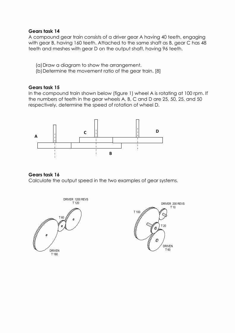
DRIVER 1200 REVST 120
T 60
DRIVENT 180
DRIVER 200 REVST 10
T 100
T 20
DRIVENT 60
Gears task 14
A compound gear train consists of a driver gear A having 40 teeth, engaging
with gear B, having 160 teeth. Attached to the same shaft as B, gear C has 48
teeth and meshes with gear D on the output shaft, having 96 teeth.
(a) Draw a diagram to show the arrangement.
(b) Determine the movement ratio of the gear train. [8]
Gears task 15
In the compound train shown below (figure 1) wheel A is rotating at 100 rpm. If
the numbers of teeth in the gear wheels A, B, C and D are 25, 50, 25, and 50
respectively, determine the speed of rotation of wheel D.
Gears task 16
Calculate the output speed in the two examples of gear systems.
A
B
C
D

Gears task 17
Four parallel shafts A, B, C, and D are connected by a simple gear train. The
number of teeth in each wheel is as follows.
A = 40
B = 25
C = 30
D = 60
If wheel A is rotating at 200 rpm in a clockwise direction, determine the
speed and direction of rotation of the other gear wheels.
Gears task 18
The compound gear train shown below is driven by a motor that runs at 750
rpm. Calculate:
(a) The output shaft speed.
(b) The ratio of the motor spindle speed to the output speed.
MOTOR
A
B
C
D
tA = 20
tB = 50
tC = 30
tC = 90

Gears task 19
A motorised winch is shown below. The motor runs at 1350 rpm and the drum
is to rotate at 54 rpm. Find the number of teeth that the motor drive gear must
have to satisfy this requirement.
Gears task 20
A compound gear train consists of an input gear A with 30 teeth that meshes
with gear B having 60 teeth. Gear C is attached to gear B and has 30 teeth.
Gear D is in mesh with gear C. Determine the number of teeth in gear D to
give a movement ratio between A and D of 5.33.
Gears task 21
Two gear wheels A and B are in mesh. Wheel A has 20 teeth and wheel B 60
teeth. Attached to wheel A is a pulley of diameter 30 mm and to wheel B a
pulley of diameter 120 mm. If an effort of 50 N is applied through a rope
wrapped around pulley B, what load attached to a rope wrapped around
pulley A would be moved? Assume the machine to be 100 per cent efficient.
MOTOR
DRUM
60 t
36 t
90 t
20 t
100 t

a b c
Gears task 22
Three different mechanisms are shown below. Name each and describe the
change in movement produced.
Example: gear train = rotational to rotational motion.
Gears task 23
Below is a mechanical device that allows rotation only in one direction.
(a) Name the device.
(b) Using an arrow on the diagram show the direction in which the device
will turn.
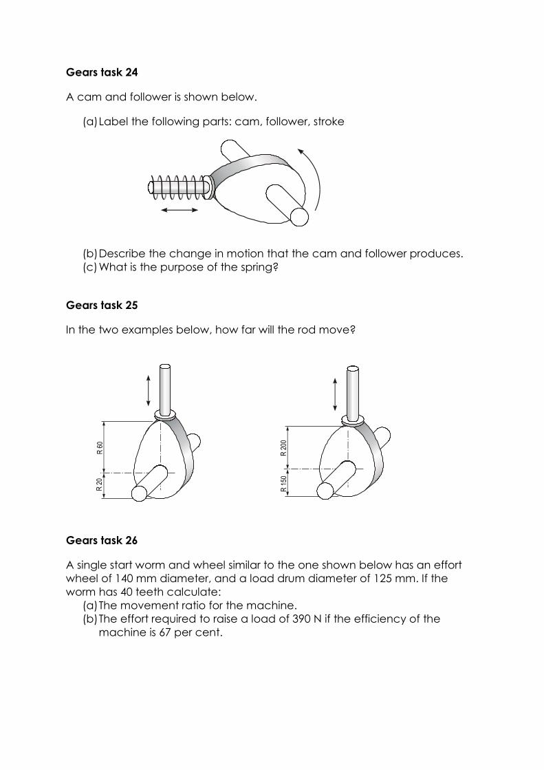
R 6
0R
20
R 2
00R
150
Gears task 24
A cam and follower is shown below.
(a) Label the following parts: cam, follower, stroke
(b) Describe the change in motion that the cam and follower produces.
(c) What is the purpose of the spring?
Gears task 25
In the two examples below, how far will the rod move?
Gears task 26
A single start worm and wheel similar to the one shown below has an effort
wheel of 140 mm diameter, and a load drum diameter of 125 mm. If the
worm has 40 teeth calculate:
(a) The movement ratio for the machine.
(b) The effort required to raise a load of 390 N if the efficiency of the
machine is 67 per cent.

CONNECTINGROD
CRANK
NEEDLE
GUIDES
RECIPROCATINGMOTION
Gears task 27
The following diagram shows a domestic sewing machine. The diagram
shows the crank and slider mechanism that is used to produce reciprocating
motion at the needle.
At its slowest operating speed, the needle moves down 120 times per minute.
At what speed does the crank rotate?

DRIVER DRIVEN
100 REVS
T 60 T 40
DRIVER DRIVEN
500 REVS
T 200 T 120
DRIVER DRIVEN
4 REVS
T 100 T 400
DRIVER DRIVEN
90 REVS
T 20 T 60
a b
c d
Gears task 28
A chain and sprocket is shown below. Label the following parts.
Driver, driven, chain, sprockets
1. Describe one advantage and one disadvantage in using a chain and
sprocket system.
2. Write down the formula for movement ratio.
3. Determine the speed of sprocket B in this chain drive if sprocket A rotates
at 150 rpm.
4. Four chain drive systems are shown below. Calculate the output speed for
each.

Ø 100
Ø 400
DRIVER200 REVS
DRIVEN
Gears task 29
1. A belt and pulley system is shown below.
(a) Calculate the output speed of the driven pulley.
(b) Describe one advantage of a belt and pulley over other drive systems.
(c) Show with a sketch how a belt and pulley system could be joined to
make the input and output turn in different directions. Label the driver
(input) and the driven (output).
2. Write down why/where you would use the following types of drive belts.
V-belt
Linked belt
Round belt
Toothed belt
3. Determine the speed of the pulley B in this belt drive if pulley A rotates
at 150 rpm.
20 t
32 t
A
B

4. The diagram shows a stepped-cone pulley system as used on some
pillar drills. By changing the position of the V-belt, three different shaft
speeds can be obtained.
(a) In which position must the belt be engaged to provide the highest drill
speed?
(b) If the drive motor runs at 1400 rpm, what is the maximum drill speed?
(c) What is the lowest speed at which the drill will run?
Gears task 30
1. Determine the torque when a pulley wheel of diameter 300 mm has a
force of 80 N applied at the rim.
2. Determine the force applied tangentially to a bar of a screwjack at a
radius of 800 mm, if the torque required is 600 N/m.
3. A constant force of 150 N is applied at a tangent to a wheel of diameter
140 mm. Determine the work done in 12 revolutions of the wheel. Your
answer should be in joules and watt-hours.
4. Calculate the torque developed by a motor whose spindle is rotating at
1000 rpm and developing a power of 2.5 kW.
Ø 10
cm
Ø 8
cm
Ø 14
cm
Ø 4
cm
SPINDLE
CHUCK
DRILL
DRIVE MOTOR
V-BELT
STEPPED-CONE
PULLEY

5. An electric motor develops a power of 3.75 kW and a torque of 12.5 N/m.
Determine the speed of rotation of the motor in rpm.
6. A pulley is 600 mm in diameter and the difference in tension on the two
sides of the driving belt is 1.5 kN. If the speed of the pulley is 500 rpm,
determine:
(a) the torque developed
(b) the work done in three minutes.
7. A 15 kW motor is driving a shaft at 1150 rpm by means of pulley wheels and
a belt. The tensions in the belt on each side of the driver pulley are 400 N
and 50 N and the diameters of the driver and driven pulley wheels are 500
mm and 750 mm respectively. Calculate:
(a) the power output
(b) the efficiency of the motor.