Embed Size (px)
Citation preview

GEM80 GEMTEQ I/O Series Controllers Publication No. T2031En Rev.02 (10/10)
Technical Manual

This page intentionally left blank.
GEMTEQ I/O Scope
GEM80
GEMTEQ I/O
Technical Manual
Publication No. T2031En Rev.02 (10/10)
GEMTEQ I/O Technical Manual (T2031En) Page iiiRev.02 (10/10)

Scope GEMTEQ I/O
Acknowledgement Issue Information Publication T2031En Issue 1 (09/10) Manufacturer
Converteam UK Ltd.
West Avenue,
Kidsgrove,
Stoke-on-Trent,
Staffordshire,
ST7 1TW
England.
Tel: +44 (0) 1782 781000
Fax: +44 (0) 1782 781133
e-mail: [email protected] © CONVERTEAM UK - 2010 - Publication No. T2031En Issue 1 (09/10) The logo CONVERTEAM and their frameworks are trademarks and service trademark applications of Converteam UK.
GEMTEQ I/O Technical Manual (T2031En) Page iv Rev.02 (10/10)
GEMTEQ I/O Scope
SAFETY INSTRUCTIONS
Care has been taken with the design of this product to ensure that it is safe. However, in common with all products of this type, misuse can result in injury or death. Therefore, it is very important that the instructions in this manual and on the product are observed during transportation, commissioning, operation, maintenance and disposal.
This technical manual should be regarded as part of the product. It should be stored with the product and passed on to any subsequent owner or user.
Local safety laws and regulations must always be observed.
Persons working on the product must be suitably skilled and should have been trained in that work for these products.
The product is a component designed for incorporation in installations, apparatus and machines.
The product must not be used as a single item safety system. In applications where maloperation of the product could cause danger, additional means must be used to prevent danger to persons.
Product approvals and certifications will be invalidated if the product is transported, used or stored outside its ratings or if the instructions in this manual are not observed.
In the European Union:
Products within the scope of the Low Voltage Directive, 2006/95/EC as amended are CE marked.
The product complies with the essential protection requirements of the EMC directive 2004/108/EC as amended, when installed and used as described in this manual. The requirements of the EMC Directive should be established before any installation, apparatus or machine which incorporates the product is taken into service.
A machine should not be taken into service until the machine has been declared in conformity with the provisions of the Machinery (Safety) Directive, 98/37/EEC.
GEMTEQ I/O Technical Manual (T2031En) Page vRev.02 (10/10)

Scope GEMTEQ I/O
This page intentionally left blank.
GEMTEQ I/O Technical Manual (T2031En) Page vi Rev.02 (10/10)
GEMTEQ I/O Scope
Scope
This publication provides details of the GEM80 GEMCAN I/O Scanner module and GEMTEQ I/O structure, which is a distributed I/O system for GEM80-500 controllers. An overview of the product and its features and specification are included in this publication as well as details to enable system Configuration, Programming, Installation and Commissioning, Maintenance and Fault Finding to be carried out.
The host GEM80 controller Technical Manual should be read in conjunction with this GEMTEQ I/O Technical Manual. This publication (T2031En) should be regarded as part of the GEMTEQ I/O product. It should be retained for the life of the product and passed on to any subsequent owner or user.
GEMTEQ I/O Technical Manual (T2031En) Page viiRev.02 (10/10)

Scope GEMTEQ I/O
This page intentionally left blank
GEMTEQ I/O Technical Manual (T2031En) Page viii Rev.02 (10/10)
GEMTEQ I/O Contents
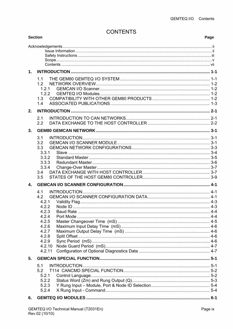
CONTENTS Section Page
Acknowledgements.......................................................................................................................................... ii Issue Information .............................................................................................................................. ii Safety Instructions ........................................................................................................................... iii Scope................................................................................................................................................v Contents ......................................................................................................................................... vii
1. INTRODUCTION .................................................................................................................... 1-1 1.1 THE GEM80 GEMTEQ I/O SYSTEM........................................................................... 1-1 1.2 NETWORK OVERVIEW............................................................................................... 1-2
1.2.1 GEMCAN I/O Scanner............................................................................................ 1-2 1.2.2 GEMTEQ I/O Modules............................................................................................ 1-2
1.3 COMPATIBILITY WITH OTHER GEM80 PRODUCTS ................................................ 1-2 1.4 ASSOCIATED PUBLICATIONS................................................................................... 1-3
2. INTRODUCTION .................................................................................................................... 2-1 2.1 INTRODUCTION TO CAN NETWORKS...................................................................... 2-1 2.2 DATA EXCHANGE TO THE HOST CONTROLLER .................................................... 2-2
3. GEM80 GEMCAN NETWORK............................................................................................... 3-1 3.1 INTRODUCTION.......................................................................................................... 3-1 3.2 GEMCAN I/O SCANNER MODULE............................................................................. 3-1 3.3 GEMCAN NETWORK CONFIGURATIONS................................................................. 3-3
3.3.1 Slave ...................................................................................................................... 3-4 3.3.2 Standard Master ..................................................................................................... 3-5 3.3.3 Redundant Master .................................................................................................. 3-6 3.3.4 Change-Over Master .............................................................................................. 3-7
3.4 DATA EXCHANGE WITH HOST CONTROLLER........................................................ 3-7 3.5 STATES OF THE HOST GEM80 CONTROLLER........................................................ 3-9
4. GEMCAN I/O SCANNER CONFIGURATION........................................................................ 4-1 4.1 INTRODUCTION.......................................................................................................... 4-1 4.2 GEMCAN I/O SCANNER CONFIGURATION DATA.................................................... 4-1
4.2.1 Validity Flag............................................................................................................ 4-3 4.2.2 Node ID .................................................................................................................. 4-3 4.2.3 Baud Rate .............................................................................................................. 4-4 4.2.4 Port Mode............................................................................................................... 4-4 4.2.5 Master Changeover Time (mS) ............................................................................. 4-5 4.2.6 Maximum Input Delay Time (mS) .......................................................................... 4-6 4.2.7 Maximum Output Delay Time (mS) ....................................................................... 4-6 4.2.8 Split Offset.............................................................................................................. 4-6 4.2.9 Sync Period (mS) .................................................................................................. 4-6 4.2.10 Node Guard Period (mS)....................................................................................... 4-7 4.2.11 Configuration of Optional Diagnostics Data ........................................................... 4-7
5. GEMCAN SPECIAL FUNCTION............................................................................................ 5-1 5.1 INTRODUCTION.......................................................................................................... 5-1 5.2 T114 CANCMD SPECIAL FUNCTION........................................................................ 5-2
5.2.1 Control Language................................................................................................... 5-2 5.2.2 Status Word (Zm) and Rung Output (Q)................................................................. 5-3 5.2.3 Y Rung Input – Module, Port & Node ID Selection................................................. 5-4 5.2.4 X Rung Input - Command....................................................................................... 5-4
6. GEMTEQ I/O MODULES ....................................................................................................... 6-1
GEMTEQ I/O Technical Manual (T2031En) Page ixRev.02 (10/10)
Contents GEMTEQ I/O
6.1 INTRODUCTION...........................................................................................................6-1 6.2 GEMTEQ I/O MODULES ..............................................................................................6-1
6.2.1 24 V d.c 16-way Input Module, Normal/Inverse Logic (9730) .................................6-1 6.2.2 24 V d.c., 0.5A, 16-way Output Module (9731) .......................................................6-1 6.2.3 110 V a.c. 16-way Input Module (9732) ..................................................................6-1 6.2.4 110 V a.c., 1A, 16-way Output Module (9733) ........................................................6-2 6.2.5 8 In / 8 Out Combination Analogue Module (9734) .................................................6-2 6.2.6 Relay, 3A, 16-way Output Module (9735) ...............................................................6-2 6.2.7 4 Channel Counter Module (9736)..........................................................................6-2 6.2.8 16 Input / 8 Output Combination Analogue Module (9737) .....................................6-2
6.3 MODULE CONFIGURATION........................................................................................6-3 6.3.1 Node ID ...................................................................................................................6-3 6.3.2 Baud Rate ...............................................................................................................6-4
6.4 CONNECTIONS............................................................................................................6-4 6.4.1 CAN Network Connections .....................................................................................6-4 6.4.2 Power Supply Connections .....................................................................................6-5 6.4.3 Plant I/O Connections .............................................................................................6-5
6.5 MODULE DIAGNOSTICS .............................................................................................6-6 6.5.1 Power Supply LEDs ................................................................................................6-6 6.5.2 OK LED ...................................................................................................................6-6 6.5.3 Communications LEDs............................................................................................6-6
6.6 APPLICATION CONFIGURATION DATA.....................................................................6-7 6.6.1 Input Filter Time ......................................................................................................6-7 6.6.2 PDO Silence Time...................................................................................................6-7 6.6.3 Freeze/Fallback.......................................................................................................6-7 6.6.4 Analog Input – Voltage or Current Input Mode........................................................6-8 6.6.5 Analog Input – 0-20mA or 4-20mA Input Mode.......................................................6-8
7. INSTALLATION AND COMMISSIONING ..............................................................................7-1 7.1 INTRODUCTION...........................................................................................................7-1
7.1.1 Unpacking and Checking the Consignment ............................................................7-1 7.1.2 What to do if something is missing or damaged .....................................................7-1
7.2 STORING GEM80 EQUIPMENT BEFORE INSTALLATION ........................................7-2 7.2.1 Environmental Conditions and Protection ...............................................................7-2
7.3 SITE REQUIREMENTS ................................................................................................7-2 7.3.1 Protection of Equipment from Static Damage .........................................................7-2
7.4 COMMISSIONING GUIDANCE ....................................................................................7-3 7.4.1 Preparation..............................................................................................................7-3 7.4.2 Documents Required ..............................................................................................7-3 7.4.3 Handling Precautions During Setting Up of Equipment ..........................................7-3 7.4.4 Radio Frequency Interference (RFI) .......................................................................7-4
8. MAINTENANCE AND FAULT FINDING.................................................................................8-1 8.1 GENERAL GUIDANCE FOR MAINTENANCE .............................................................8-1 8.2 FAULT TABLE DATA....................................................................................................8-1
8.2.1 Module P-Table Configuration Data Errors .............................................................8-2 8.2.2 Communications Statistics ......................................................................................8-4 8.2.3 Node Presence .......................................................................................................8-5
8.3 DIAGNOSTICS DATA...................................................................................................8-5 8.3.1 Node Data (Px+23-24, Px52-P53) ..........................................................................8-5 8.3.2 Input PDO Fault Data..............................................................................................8-6 8.3.3 Output PDO Fault Data ...........................................................................................8-7
8.4 REPAIRS TO GEM80 EQUIPMENT.............................................................................8-8 8.5 FAULT FINDING BACK-UP AND MODULE REPAIR SERVICE ..................................8-8 8.6 DISPOSAL ....................................................................................................................8-9
GEMTEQ I/O Technical Manual (T2031En) Page x APPENDIX A GEM80-500 GEMCAN I/O SCANNER : MODULE 1 DATA SUMMARY............1
Rev.02 (10/10)
GEMTEQ I/O Contents
APPENDIX B GEMTEQ I/O MODULE INSTRUCTION SHEETS ...................................................1
APPENDIX C NODE GUARD PERIOD AND MASTER CHANGEOVER TIME..............................1
GEMTEQ I/O Technical Manual (T2031En) Page xiRev.02 (10/10)
Contents GEMTEQ I/O
LIST OF FIGURES Figure 2-1 Network Cabling between 4 Nodes ....................................................................................2-1 Figure 2-2 GEMCAN I/O Scanner Data Exchange with Host PLC......................................................2-2 Figure 3-1 Simple GEMTEQ I/O Network ............................................................................................3-1 Figure 3-2 9720-4020 GEMCAN I/O Scanner Module ........................................................................3-1 Figure 3-3 9720-4020 GEMCAN I/O Scanner Port Identification and Configuration...........................3-2 Figure 3-4 GEMCAN I/O Scanner – Slave Operation..........................................................................3-4 Figure 3-5 GEMCAN I/O Scanner – Master Operation........................................................................3-5 Figure 3-6 GEMCAN I/O Scanner – Redundant Master Operation.....................................................3-6 Figure 3-7 GEMCAN I/O Scanner – Change-over Master Operation..................................................3-7 Figure 6-1 CAN Network Connections – Middle of Link ......................................................................6-4 Figure 6-2 CAN Network Connections – End of Link...........................................................................6-5 Figure 6-3 GEMTEQ I/O Module – Power Supply Connections.........................................................6-5
GEMTEQ I/O Technical Manual (T2031En) Page xii Rev.02 (10/10)
GEMTEQ I/O Contents
LIST OF TABLES Table 3-1 C/D-Table Allocation – Node ID 1...................................................................................... 3-9 Table 4-1 P-Tables reserved for GEMCAN I/O Scanner Configuration Data.................................... 4-1 Table 4-2 GEMCAN I/O Scanner - Node ID Selection....................................................................... 4-3 Table 4-3 GEMCAN I/O Scanner - Baud Rate Selection & Maximum Bus Length ........................... 4-4 Table 4-4 GEMCAN I/O Scanner - Operating Mode.......................................................................... 4-4 Table 4-5 GEMCAN I/O Scanner – Port Sub Mode........................................................................... 4-5 Table 4-6 Default Node Guard Period................................................................................................ 4-7 Table 5-1 CANCMD - Program Rung Data........................................................................................ 5-2 Table 5-2 CANCMD - Value Data ...................................................................................................... 5-2 Table 5-3 CANCMD – Status Word and Rung Output Values........................................................... 5-3 Table 5-4 CANCMD – Command Data .............................................................................................. 5-4 Table 6-1 GEMTEQ I/O Modules ....................................................................................................... 6-1 Table 6-2 GEMTEQ I/O Module – Node ID Selection........................................................................ 6-3 Table 6-3 GEMTEQ I/O Module - Baud Rate Selection..................................................................... 6-4 Table 6-4 GEMTEQ I/O Module – OK LED........................................................................................ 6-6 Table 8-1 GEMCAN I/O Scanner - F-Table Fault Data...................................................................... 8-1 Table 8-2 GEMCAN I/O Scanner Module Configuration Errors......................................................... 8-2 Table 8-3 Configuration Error Codes ................................................................................................. 8-3 Table 8-4 Communications Statistics................................................................................................. 8-4 Table 8-5 Node Presence .................................................................................................................. 8-5 Table 8-6 Node Data .......................................................................................................................... 8-5 Table 8-7 Input PDO Fault Data......................................................................................................... 8-6 Table 8-8 Output PDO Fault Data...................................................................................................... 8-7
GEMTEQ I/O Technical Manual (T2031En) Page xiiiRev.02 (10/10)

Contents GEMTEQ I/O
This page left intentionally blank
GEMTEQ I/O Technical Manual (T2031En) Page xiv Rev.02 (10/10)
GEMTEQ I/O 1. Introduction
1. INTRODUCTION GEMTEQ is a generation of distributed I/O modules specifically for the GEM80-500 range of programmable logic controllers. Designed as the interface between the plant and the GEM80 controller, the complete modular family provides a flexible, simple and intelligent device.
GEMTEQ I/O is designed with advanced features and functions making them intelligent and capable, yet easy and intuitive to use. GEMTEQ’s diagnostics and ability to use dual networks and redundant/changeover masters makes it ideal where high availability, high reliability architecture is required.
Features ● I/O wherever you need it
- Local to PLC or - Distributed I/O
● Modular and scaleable architecture ● Redundant PLC and high availability configurations ● Cost efficient solutions
- Fast installation - Reduced wiring
● GEMTEQ I/O can save system builders and end users considerable time and money ● Quick connect wiring ● Distributed I/O modules ● Redundant link capability ● 125 modules per scanner module ● Dual Network Ports ● Each link independently configurable ● Scanner can be configured as master, slave, redundant, change over ● Network length up to 5000 metres ● In current mode configurable 0-20ma or 4-20ma ● Communication speed up to 1M baud ● Digital inputs configurable DBounce time ● Freeze/Fallback configuration on output on a per I/O point basis
1.1 THE GEM80 GEMTEQ I/O SYSTEM Converteam’s distributed I/O module system provides the latest in compact flexibility allowing the user to install the required amount of I/O where it is required.
● Redundant link capability allows the user to change modules without shutting down their machine, optimising productivity and minimising downtime.
● Extensive diagnostics make identifying faults a matter of routine maximising up-time.
● Dual network ports.
● Redundant cabling – I/O modules will always be connected to minimise downtime.
● Module freeze/fall back facility on loss of communications.
● Distributed plant – modules where you require them
GEMTEQ I/O Technical Manual (T2031En) Rev.02 (10/10)
Page 1-1
GEMTEQ I/O 1. Introduction
1.2 NETWORK OVERVIEW Each GEMTEQ I/O system consists of GEMCAN I/O Scanner module fitted in a host GEM80-500 PLC, GEMTEQ slave I/O modules, with the option of GEM80-500 PLC as slave devices.
1.2.1 GEMCAN I/O Scanner The GEMCAN I/O scanner fits into the GEM80-500 controller to provide the interface to the GEMTEQ I/O system.
● Up to 125 nodes per scanner
● 2 ports per scanner
● 2 scanners per host PLC
1.2.2 GEMTEQ I/O Modules ● Advanced diagnostics and embedded LED I/O indicators speed up troubleshooting and increase productivity.
● Hot-swap minimises downtime by allowing failed I/O modules to be changed without shutting down the plant.
● Convenient rotary switches are used for setting bus address and baud rate therefore no programming required.
● Removable wiring connectors save time and speed up commissioning.
● DIN rail mounting – no special tools required.
● Configurable digital DBounce and analogue filter times.
1.3 COMPATIBILITY WITH OTHER GEM80 PRODUCTS GEMTEQ I/O is only available on the GEM80-500 Series of Controllers. This functionality was added in the following software releases:-
00S172-4002 Issue “C”
00S203-4001 Issue “E”
For further assistance please contact Customer Support.
GEMTEQ I/O Technical Manual (T2031En) Page 1-2 Rev.02 (10/10)
GEMTEQ I/O 1. Introduction
1.4 ASSOCIATED PUBLICATIONS
CONVERTEAM Publications associated with this technical manual are now listed.
T391 GEM80 Ladder Diagram Language Programming Manual
This manual provides a competent user, who is familiar with programming GEM80 controllers, details for all aspects of programming, including the language, the Standard Instruction Set and all the GEM80 Special Functions. It does not include some Additional Instructions which are used for the GEM80-400 and 500 Series Controllers that are described in the GEM80-400 manual.
T2025En GEM80-500 Series Controllers Technical Manual
This manual provides a competent user who is familiar with GEM80 controllers details for the installation, commissioning, operation and maintenance of the GEM80-500 Series Controllers. It includes some software details which are cross-referenced from the GEM80-400 manual.
GEMTEQ I/O Technical Manual (T2031En) Rev.02 (10/10)
Page 1-3

GEMTEQ I/O 1. Introduction
This page intentionally left blank
GEMTEQ I/O Technical Manual (T2031En) Page 1-4 Rev.02 (10/10)
GEMTEQ I/O 2. Introduction to CAN Networks
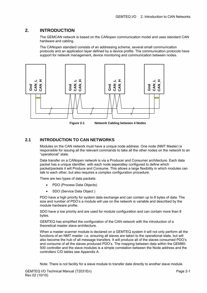
2. INTRODUCTION The GEMCAN network is based on the CANopen communication model and uses standard CAN hardware and cabling.
The CANopen standard consists of an addressing scheme, several small communication protocols and an application layer defined by a device profile. The communication protocols have support for network management, device monitoring and communication between nodes.
CA
N_H
CA
N_L
Gnd
CA
N_H
CA
N_L
Gnd
CA
N_H
CA
N_L
Gnd
CA
N_H
CA
N_L
Gnd
Figure 2-1 Network Cabling between 4 Nodes
2.1 INTRODUCTION TO CAN NETWORKS Modules on the CAN network must have a unique node address. One node (NMT Master) is responsible for issuing all the relevant commands to take all the other nodes on the network to an “operational” state.
Data transfer on a CANopen network is via a Producer and Consumer architecture. Each data packet has a unique identifier, with each node seperatley configured to define which packet/packets it will Produce and Consume. This allows a large flexibility in which modules can talk to each other, but also requires a complex configuration procedure.
There are two types of data packets:
• PDO (Process Data Objects)
• SDO (Service Data Object )
PDO have a high priority for system data exchange and can contain up to 8 bytes of data. The size and number of PDO’s a module will use on the network is variable and described by the module hardware profile.
SDO have a low priority and are used for module configuration and can contain more than 8 bytes.
GEMTEQ has simplified the configuration of the CAN network with the introduction of a theoretical master slave architecture.
When a master scanner module is declared on a GEMTEQ system it will not only perform all the functions of an NMT master .i.e. ensuring all slaves are taken to the operational state, but will also become the hub of all message transfers. It will produce all of the slaves consumed PDO’s and consume of all the slaves produced PDO’s. The mapping between data within the GEM80-500 controller and the slave modules is a simple correlation between the Node address and the controllers C/D tables see Appendix A.
Note: There is not facility for a slave module to transfer date directly to another slave module.
GEMTEQ I/O Technical Manual (T2031En) Rev.02 (10/10)
Page 2-1
GEMTEQ I/O 2. Introduction to CAN Networks
Slave GEMTEQ modules have a fixed size and number of PDO’s assigned to each module. There are 16 C/D tables (a maximum of 4 transmit and receive PDO’s) per node ID.
Any configuration data for the module is included within the 16 words of output PDO data, the GEMTEQ network does not use SDO’s to configure slave modules.
To reduce the network traffic on the GEMTEQ link, data is only normally transmitted when data changes. A slave input module will transmit data to the GEMTEQ scanner module when it detects an input change. The scanner will transmit data to a slave output module when it detects that the output data PDO has changed within the scanner module.
2.2 DATA EXCHANGE TO THE HOST CONTROLLER
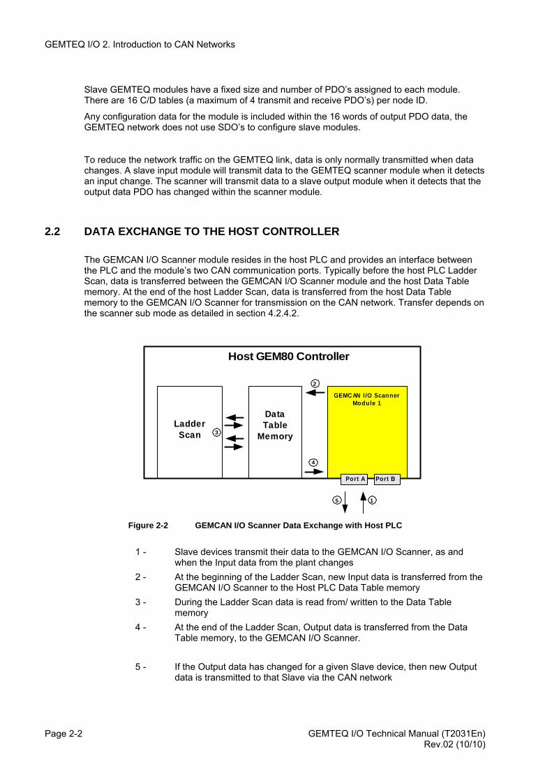
The GEMCAN I/O Scanner module resides in the host PLC and provides an interface between the PLC and the module’s two CAN communication ports. Typically before the host PLC Ladder Scan, data is transferred between the GEMCAN I/O Scanner module and the host Data Table memory. At the end of the host Ladder Scan, data is transferred from the host Data Table memory to the GEMCAN I/O Scanner for transmission on the CAN network. Transfer depends on the scanner sub mode as detailed in section 4.2.4.2.
GEMCAN I/O ScannerModule 1
Host GEM80 Controller
LadderScan
DataTable
Memory
2
3
4
15
Port BPort A
Figure 2-2 GEMCAN I/O Scanner Data Exchange with Host PLC
1 - Slave devices transmit their data to the GEMCAN I/O Scanner, as and
when the Input data from the plant changes 2 - At the beginning of the Ladder Scan, new Input data is transferred from the
GEMCAN I/O Scanner to the Host PLC Data Table memory 3 - During the Ladder Scan data is read from/ written to the Data Table
memory 4 - At the end of the Ladder Scan, Output data is transferred from the Data
Table memory, to the GEMCAN I/O Scanner.
5 - If the Output data has changed for a given Slave device, then new Output data is transmitted to that Slave via the CAN network
GEMTEQ I/O Technical Manual (T2031En) Page 2-2 Rev.02 (10/10)
GEMTEQ I/O 3. GEM80 GEMCAN NETWORK
3. GEM80 GEMCAN NETWORK
3.1 INTRODUCTION
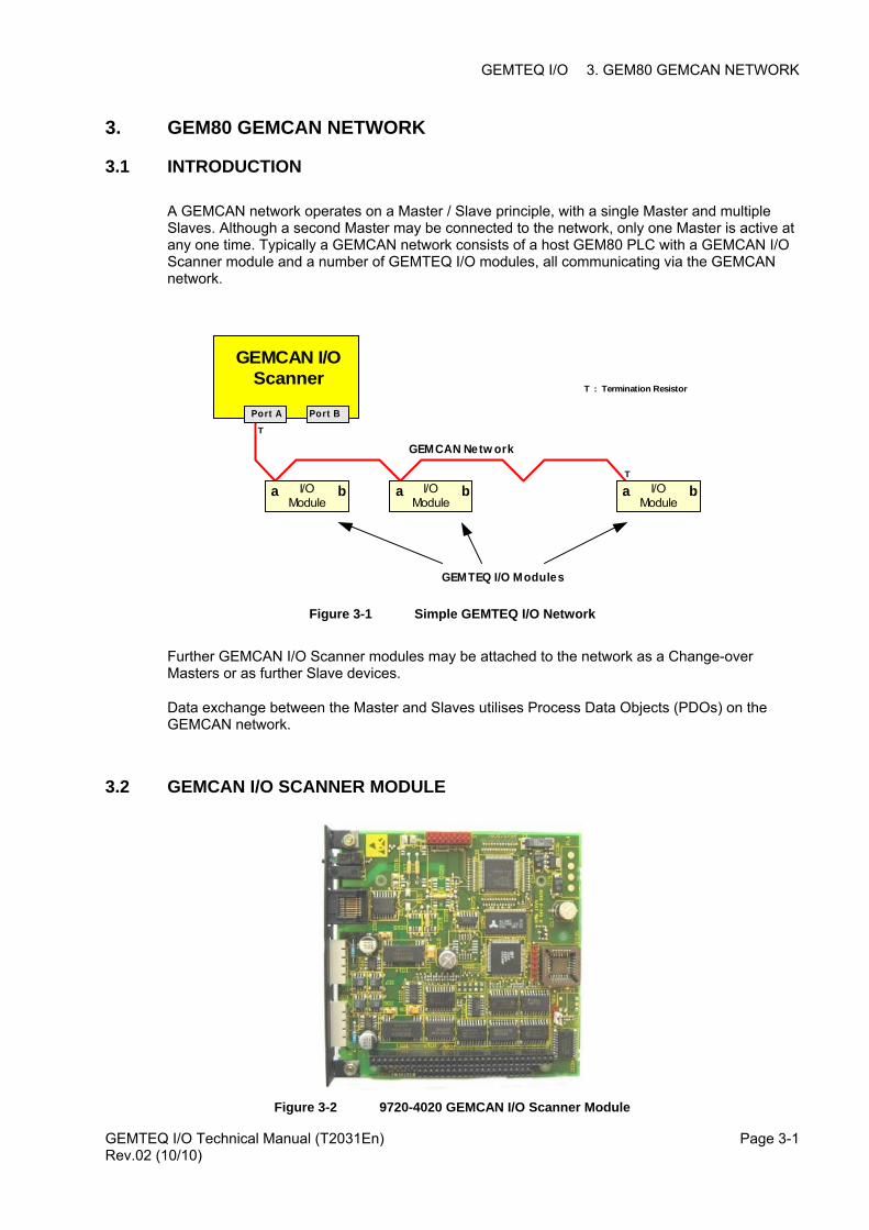
A GEMCAN network operates on a Master / Slave principle, with a single Master and multiple Slaves. Although a second Master may be connected to the network, only one Master is active at any one time. Typically a GEMCAN network consists of a host GEM80 PLC with a GEMCAN I/O Scanner module and a number of GEMTEQ I/O modules, all communicating via the GEMCAN network.
GEMCAN I/OScanner
T
T
Port A Port B
GEMCAN Netw ork
I/OModule
a bI/OModule
a bI/OModule
a b
T : Termination Resistor
GEMTEQ I/O Modules
Figure 3-1 Simple GEMTEQ I/O Network
Further GEMCAN I/O Scanner modules may be attached to the network as a Change-over Masters or as further Slave devices.
Data exchange between the Master and Slaves utilises Process Data Objects (PDOs) on the GEMCAN network.
3.2 GEMCAN I/O SCANNER MODULE
Figure 3-2 9720-4020 GEMCAN I/O Scanner Module
GEMTEQ I/O Technical Manual (T2031En) Rev.02 (10/10)
Page 3-1
GEMTEQ I/O 3. GEM80 GEMCAN NETWORK
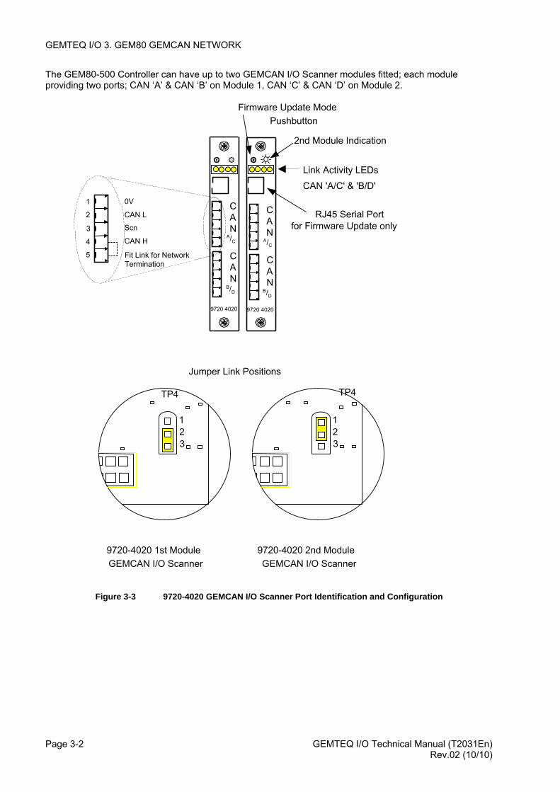
The GEM80-500 Controller can have up to two GEMCAN I/O Scanner modules fitted; each module providing two ports; CAN ‘A’ & CAN ‘B’ on Module 1, CAN ‘C’ & CAN ‘D’ on Module 2.
GEMTEQ I/O Technical Manual (T2031En) Page 3-2
Figure 3-3 9720-4020 GEMCAN I/O Scanner Port Identification and Configuration
CAN
A /C
CAN
B /D
9720 4020
CAN
A/C
CAN
B/D
9720 4020
9720-4020 1st Module GEMCAN I/O Scanner
Firmware Update ModePushbutton
9720-4020 2nd ModuleGEMCAN I/O Scanner
TP4
1 2 3
TP4
123
Jumper Link Positions
2nd Module Indication
Link Activity LEDs
CAN 'A/C' & 'B/D'0V CAN L Scn CAN H Fit Link for Network Termination
1 2 3 4 5
RJ45 Serial Portfor Firmware Update only
Rev.02 (10/10)
GEMTEQ I/O 3. GEM80 GEMCAN NETWORK
3.3 GEMCAN NETWORK CONFIGURATIONS
The GEMCAN I/O Scanner Ports may be configured to operate in four different modes.
Slave
Standard Master
Redundant Master
Change-over Master
The following sections describe the operation of each of these modes and any restrictions on the combination of modes on a given GEMCAN I/O Scanner module.
GEMTEQ I/O Technical Manual (T2031En) Rev.02 (10/10)
Page 3-3
GEMTEQ I/O 3. GEM80 GEMCAN NETWORK
3.3.1 Slave
GEMCAN I/O ScannerModule 1
GEMCAN I/O ScannerModule 2
GEM80-500
Slav ePort A Port B Port C Port D
Master
T
T T : Termination Resistor
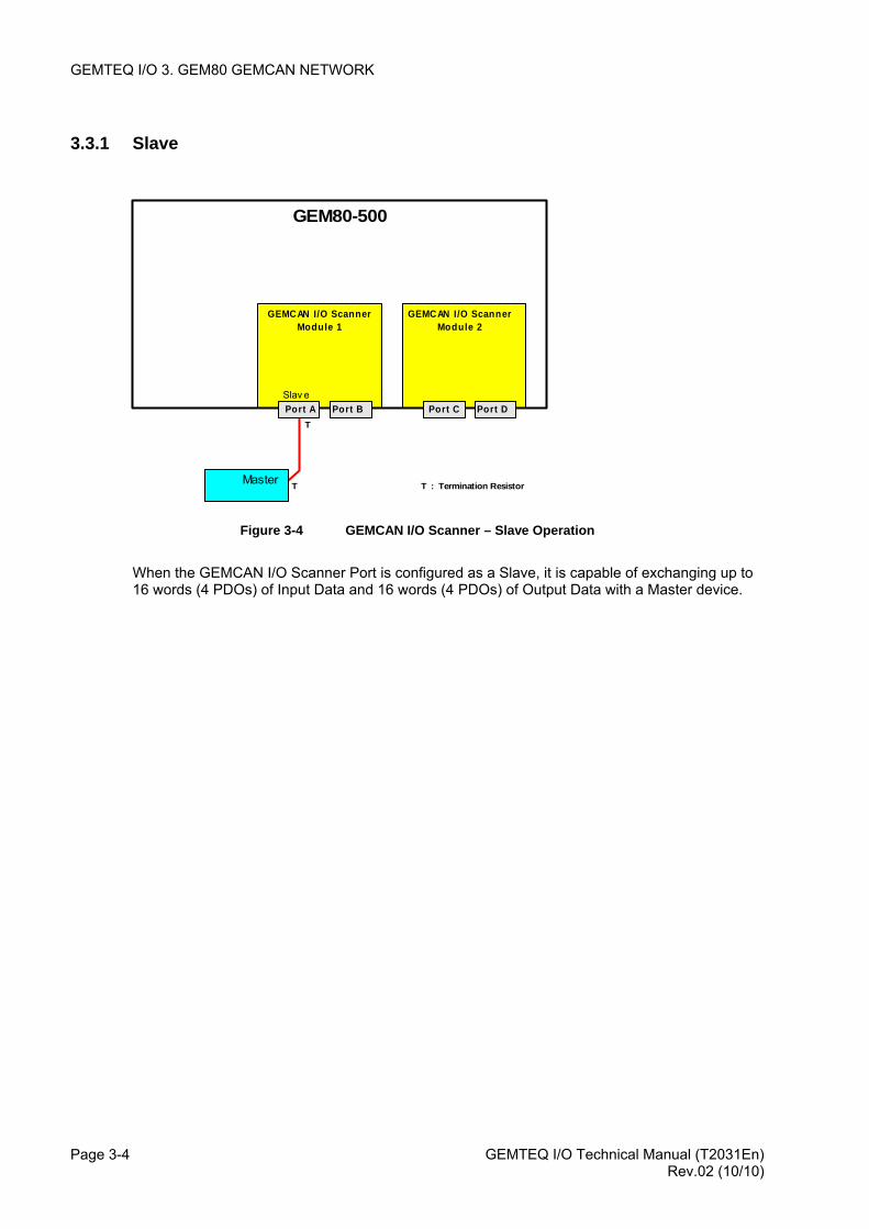
Figure 3-4 GEMCAN I/O Scanner – Slave Operation
When the GEMCAN I/O Scanner Port is configured as a Slave, it is capable of exchanging up to 16 words (4 PDOs) of Input Data and 16 words (4 PDOs) of Output Data with a Master device.
GEMTEQ I/O Technical Manual (T2031En) Page 3-4 Rev.02 (10/10)
GEMTEQ I/O 3. GEM80 GEMCAN NETWORK
3.3.2 Standard Master
GEMCAN I/O ScannerModule 1
GEMCAN I/O ScannerModule 2
GEM80-500
MasterPort A Port B Port C Port D
I/OModule
ab
I/OModule
ab
I/OModule
a b
I/OModule
a b
I/OModule
ab I/OModule
a b
TT
T T
T : Termination Resistor
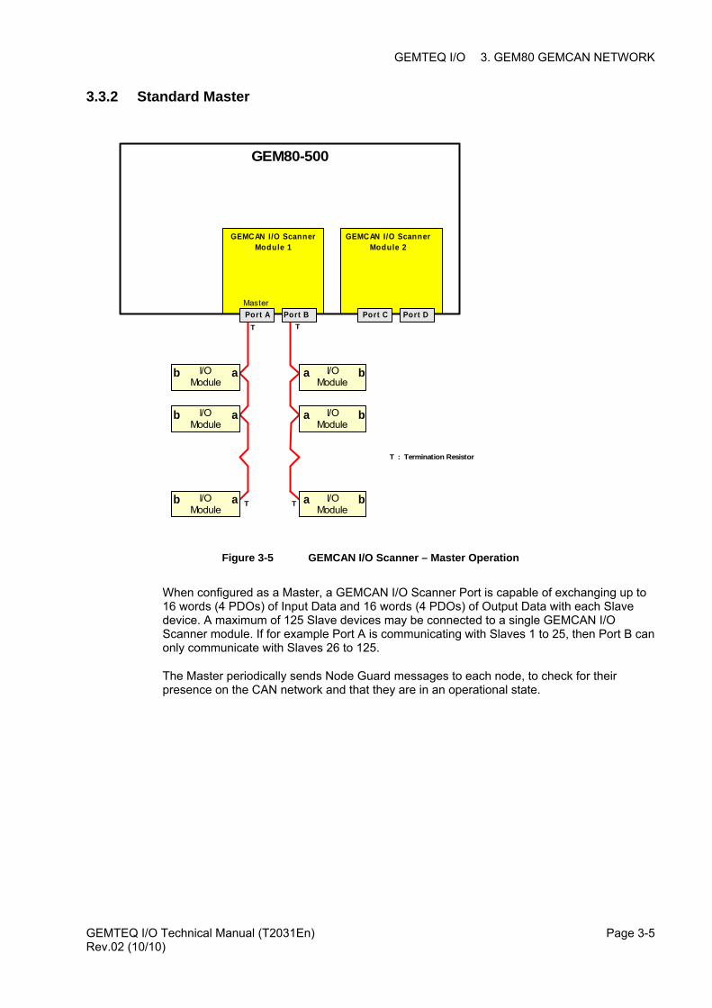
Figure 3-5 GEMCAN I/O Scanner – Master Operation
When configured as a Master, a GEMCAN I/O Scanner Port is capable of exchanging up to 16 words (4 PDOs) of Input Data and 16 words (4 PDOs) of Output Data with each Slave device. A maximum of 125 Slave devices may be connected to a single GEMCAN I/O Scanner module. If for example Port A is communicating with Slaves 1 to 25, then Port B can only communicate with Slaves 26 to 125.
The Master periodically sends Node Guard messages to each node, to check for their presence on the CAN network and that they are in an operational state.
GEMTEQ I/O Technical Manual (T2031En) Rev.02 (10/10)
Page 3-5
GEMTEQ I/O 3. GEM80 GEMCAN NETWORK
3.3.3 Redundant Master
GEMCAN I/O ScannerModule 1
GEMCAN I/O ScannerModule 2
GEM80-500
RedundantMaster
Port A Port B Port C Port D
I/OModule
a b
I/OModule
a b
I/OModule
a b
T T
TT
RedundantMaster
T : Termination Resistor
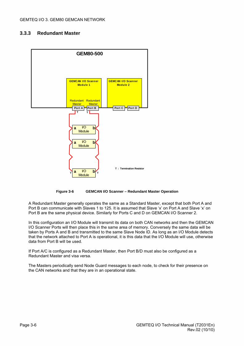
Figure 3-6 GEMCAN I/O Scanner – Redundant Master Operation
A Redundant Master generally operates the same as a Standard Master, except that both Port A and Port B can communicate with Slaves 1 to 125. It is assumed that Slave ‘x’ on Port A and Slave ‘x’ on Port B are the same physical device. Similarly for Ports C and D on GEMCAN I/O Scanner 2.
In this configuration an I/O Module will transmit its data on both CAN networks and then the GEMCAN I/O Scanner Ports will then place this in the same area of memory. Conversely the same data will be taken by Ports A and B and transmitted to the same Slave Node ID. As long as an I/O Module detects that the network attached to Port A is operational, it is this data that the I/O Module will use, otherwise data from Port B will be used.
If Port A/C is configured as a Redundant Master, then Port B/D must also be configured as a Redundant Master and visa versa.
The Masters periodically send Node Guard messages to each node, to check for their presence on the CAN networks and that they are in an operational state.
GEMTEQ I/O Technical Manual (T2031En) Page 3-6 Rev.02 (10/10)
GEMTEQ I/O 3. GEM80 GEMCAN NETWORK
3.3.4 Change-Over Master
GEMCAN I/O ScannerModule 1
GEMCAN I/O ScannerModule 2
GEM80-500
Changeov erMasterPort A Port B Port C Port D
I/OModule
a b
I/OModule
a b
I/OModule
a bT
GEMCAN I/O ScannerModule 1
GEMCAN I/O ScannerModule 2
GEM80-500
Port A Port B Port C Port DT
Changeov erMaster
'X' 'Y'
T : Termination Resistor
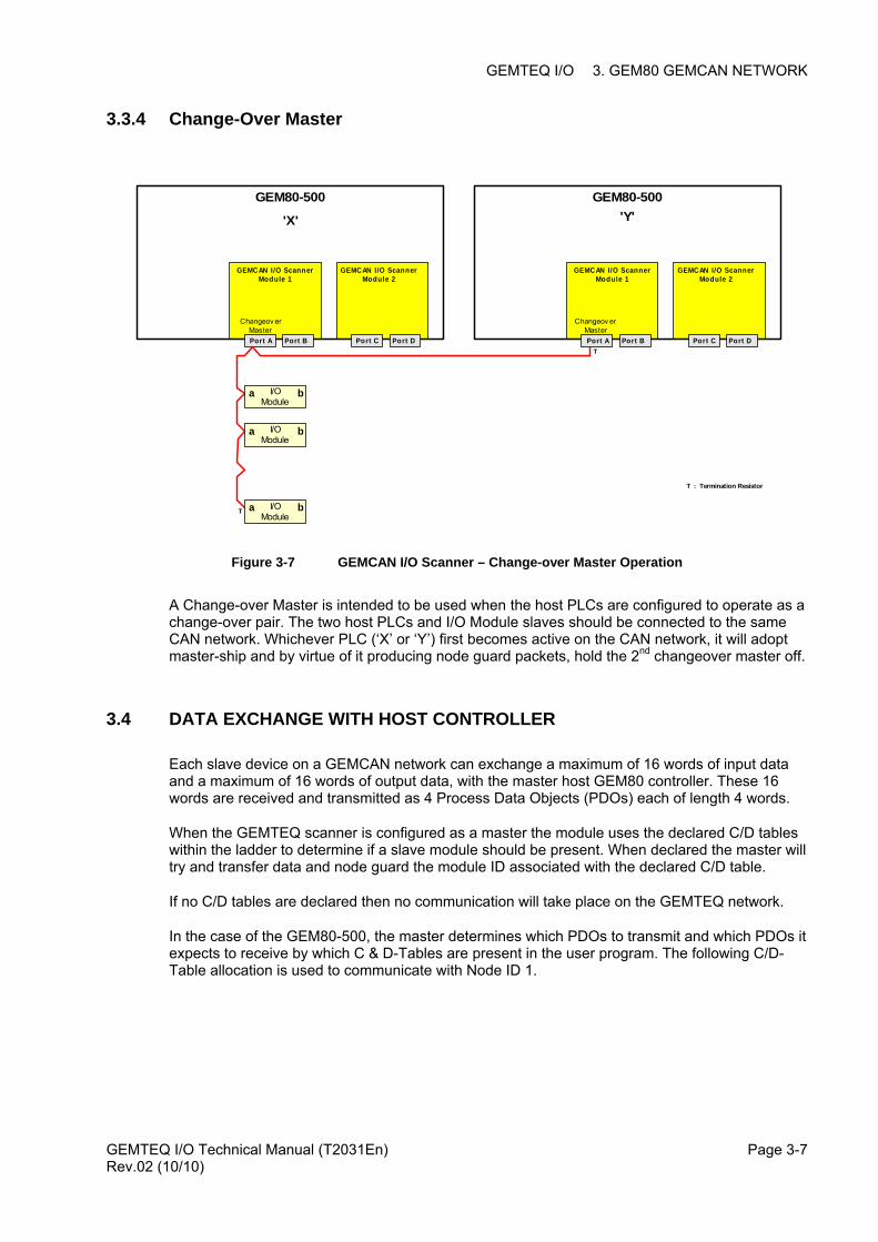
Figure 3-7 GEMCAN I/O Scanner – Change-over Master Operation
A Change-over Master is intended to be used when the host PLCs are configured to operate as a change-over pair. The two host PLCs and I/O Module slaves should be connected to the same CAN network. Whichever PLC (‘X’ or ‘Y’) first becomes active on the CAN network, it will adopt master-ship and by virtue of it producing node guard packets, hold the 2nd changeover master off.
3.4 DATA EXCHANGE WITH HOST CONTROLLER
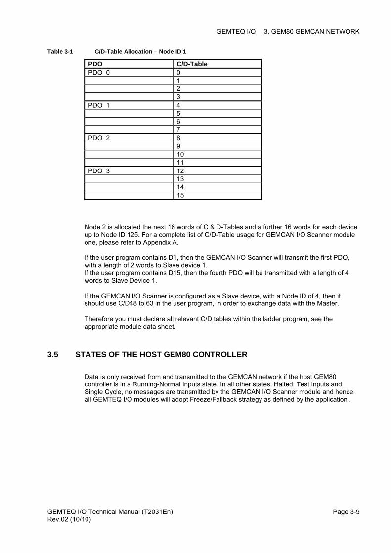
Each slave device on a GEMCAN network can exchange a maximum of 16 words of input data and a maximum of 16 words of output data, with the master host GEM80 controller. These 16 words are received and transmitted as 4 Process Data Objects (PDOs) each of length 4 words.
When the GEMTEQ scanner is configured as a master the module uses the declared C/D tables within the ladder to determine if a slave module should be present. When declared the master will try and transfer data and node guard the module ID associated with the declared C/D table.
If no C/D tables are declared then no communication will take place on the GEMTEQ network.
In the case of the GEM80-500, the master determines which PDOs to transmit and which PDOs it expects to receive by which C & D-Tables are present in the user program. The following C/D-Table allocation is used to communicate with Node ID 1.
GEMTEQ I/O Technical Manual (T2031En) Rev.02 (10/10)
Page 3-7

GEMTEQ I/O 3. GEM80 GEMCAN NETWORK
GEMTEQ I/O Technical Manual (T2031En) Page 3-8 Rev.02 (10/10)
GEMTEQ I/O 3. GEM80 GEMCAN NETWORK
Table 3-1 C/D-Table Allocation – Node ID 1
PDO C/D-Table PDO 0 0 1 2 3 PDO 1 4 5 6 7 PDO 2 8 9 10 11 PDO 3 12 13 14 15
Node 2 is allocated the next 16 words of C & D-Tables and a further 16 words for each device up to Node ID 125. For a complete list of C/D-Table usage for GEMCAN I/O Scanner module one, please refer to Appendix A.
If the user program contains D1, then the GEMCAN I/O Scanner will transmit the first PDO, with a length of 2 words to Slave device 1. If the user program contains D15, then the fourth PDO will be transmitted with a length of 4 words to Slave Device 1.
If the GEMCAN I/O Scanner is configured as a Slave device, with a Node ID of 4, then it should use C/D48 to 63 in the user program, in order to exchange data with the Master.
Therefore you must declare all relevant C/D tables within the ladder program, see the appropriate module data sheet.
3.5 STATES OF THE HOST GEM80 CONTROLLER
Data is only received from and transmitted to the GEMCAN network if the host GEM80 controller is in a Running-Normal Inputs state. In all other states, Halted, Test Inputs and Single Cycle, no messages are transmitted by the GEMCAN I/O Scanner module and hence all GEMTEQ I/O modules will adopt Freeze/Fallback strategy as defined by the application .
GEMTEQ I/O Technical Manual (T2031En) Rev.02 (10/10)
Page 3-9

GEMTEQ I/O 3. GEM80 GEMCAN NETWORK
GEMTEQ I/O Technical Manual (T2031En) Page 3-10 Rev.02 (10/10)
GEMTEQ I/O 4. GEMCAN I/O Scanner Configuration
4. GEMCAN I/O SCANNER CONFIGURATION
4.1 INTRODUCTION
This section describes the P-Table configuration data that is required to allow a GEMCAN I/O Scanner module to take part in the data exchanges on a GEMCAN network, either as a Master or as a Slave device.
4.2 GEMCAN I/O SCANNER CONFIGURATION DATA
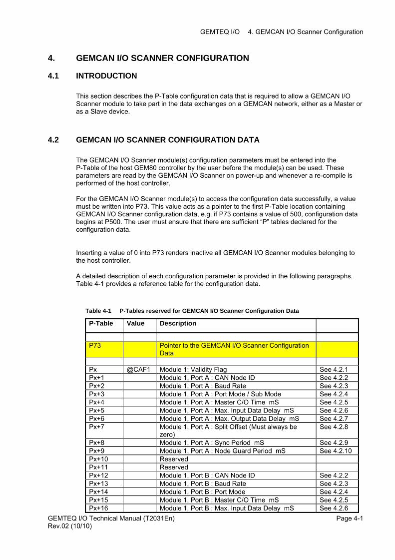
The GEMCAN I/O Scanner module(s) configuration parameters must be entered into the P-Table of the host GEM80 controller by the user before the module(s) can be used. These parameters are read by the GEMCAN I/O Scanner on power-up and whenever a re-compile is performed of the host controller.
For the GEMCAN I/O Scanner module(s) to access the configuration data successfully, a value must be written into P73. This value acts as a pointer to the first P-Table location containing GEMCAN I/O Scanner configuration data, e.g. if P73 contains a value of 500, configuration data begins at P500. The user must ensure that there are sufficient “P” tables declared for the configuration data.
Inserting a value of 0 into P73 renders inactive all GEMCAN I/O Scanner modules belonging to the host controller.
A detailed description of each configuration parameter is provided in the following paragraphs. Table 4-1 provides a reference table for the configuration data.
Table 4-1 P-Tables reserved for GEMCAN I/O Scanner Configuration Data
P-Table Value Description
P73 Pointer to the GEMCAN I/O Scanner Configuration
Data
Px @CAF1 Module 1: Validity Flag See 4.2.1Px+1 Module 1, Port A : CAN Node ID See 4.2.2Px+2 Module 1, Port A : Baud Rate See 4.2.3Px+3 Module 1, Port A : Port Mode / Sub Mode See 4.2.4Px+4 Module 1, Port A : Master C/O Time mS See 4.2.5Px+5 Module 1, Port A : Max. Input Data Delay mS See 4.2.6Px+6 Module 1, Port A : Max. Output Data Delay mS See 4.2.7Px+7 Module 1, Port A : Split Offset (Must always be
zero) See 4.2.8
Px+8 Module 1, Port A : Sync Period mS See 4.2.9Px+9 Module 1, Port A : Node Guard Period mS See 4.2.10Px+10 Reserved Px+11 Reserved Px+12 Module 1, Port B : CAN Node ID See 4.2.2Px+13 Module 1, Port B : Baud Rate See 4.2.3Px+14 Module 1, Port B : Port Mode See 4.2.4Px+15 Module 1, Port B : Master C/O Time mS See 4.2.5Px+16 Module 1, Port B : Max. Input Data Delay mS See 4.2.6
GEMTEQ I/O Technical Manual (T2031En) Rev.02 (10/10)
Page 4-1
GEMTEQ I/O 4. GEMCAN I/O Scanner Configuration
GEMTEQ I/O Technical Manual (T2031En) Page 4-2
P-Table Value Description
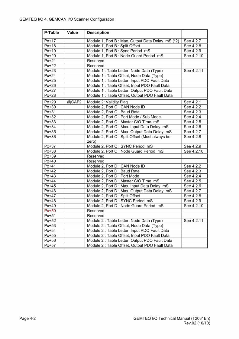
Px+17 Module 1, Port B : Max. Output Data Delay mS (*2) See 4.2.7Px+18 Module 1, Port B : Split Offset See 4.2.8Px+19 Module 1, Port B : Sync Period mS See 4.2.9Px+20 Module 1, Port B : Node Guard Period mS See 4.2.10Px+21 Reserved Px+22 Reserved Px+23 Module 1 : Table Letter, Node Data (Type) See 4.2.11Px+24 Module 1 : Table Offset, Node Data (Type) Px+25 Module 1 : Table Letter, Input PDO Fault Data Px+26 Module 1 : Table Offset, Input PDO Fault Data Px+27 Module 1 : Table Letter, Output PDO Fault Data Px+28 Module 1 : Table Offset, Output PDO Fault Data Px+29 @CAF2 Module 2: Validity Flag See 4.2.1Px+30 Module 2, Port C : CAN Node ID See 4.2.2Px+31 Module 2, Port C : Baud Rate See 4.2.3Px+32 Module 2, Port C : Port Mode / Sub Mode See 4.2.4Px+33 Module 2, Port C : Master C/O Time mS See 4.2.5Px+34 Module 2, Port C : Max. Input Data Delay mS See 4.2.6Px+35 Module 2, Port C : Max. Output Data Delay mS See 4.2.7Px+36 Module 2, Port C : Split Offset (Must always be
zero) See 4.2.8
Px+37 Module 2, Port C : SYNC Period mS See 4.2.9Px+38 Module 2, Port C : Node Guard Period mS See 4.2.10Px+39 Reserved Px+40 Reserved Px+41 Module 2, Port D : CAN Node ID See 4.2.2Px+42 Module 2, Port D : Baud Rate See 4.2.3Px+43 Module 2, Port D : Port Mode See 4.2.4Px+44 Module 2, Port D : Master C/O Time mS See 4.2.5Px+45 Module 2, Port D : Max. Input Data Delay mS See 4.2.6Px+46 Module 2, Port D : Max. Output Data Delay mS See 4.2.7Px+47 Module 2, Port D : Split Offset See 4.2.8Px+48 Module 2, Port D : SYNC Period mS See 4.2.9Px+49 Module 2, Port D : Node Guard Period mS See 4.2.10Px+50 Reserved Px+51 Reserved Px+52 Module 2 : Table Letter, Node Data (Type) See 4.2.11Px+53 Module 2 : Table Offset, Node Data (Type) Px+54 Module 2 : Table Letter, Input PDO Fault Data Px+55 Module 2 : Table Offset, Input PDO Fault Data Px+56 Module 2 : Table Letter, Output PDO Fault Data Px+57 Module 2 : Table Offset, Output PDO Fault Data
Rev.02 (10/10)
GEMTEQ I/O 4. GEMCAN I/O Scanner Configuration
4.2.1 Validity Flag Module 1 Px / Module 2 Px29)
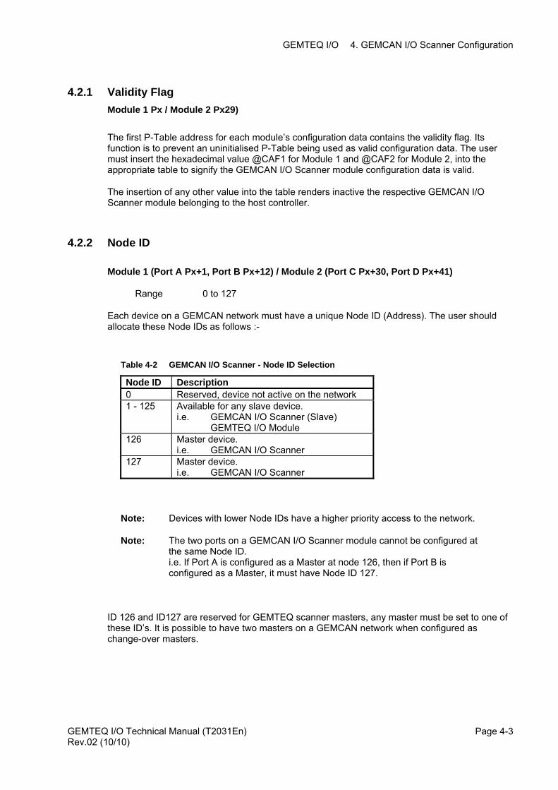
The first P-Table address for each module’s configuration data contains the validity flag. Its function is to prevent an uninitialised P-Table being used as valid configuration data. The user must insert the hexadecimal value @CAF1 for Module 1 and @CAF2 for Module 2, into the appropriate table to signify the GEMCAN I/O Scanner module configuration data is valid.
The insertion of any other value into the table renders inactive the respective GEMCAN I/O Scanner module belonging to the host controller.
4.2.2 Node ID
Module 1 (Port A Px+1, Port B Px+12) / Module 2 (Port C Px+30, Port D Px+41)
Range 0 to 127
Each device on a GEMCAN network must have a unique Node ID (Address). The user should allocate these Node IDs as follows :-
Table 4-2 GEMCAN I/O Scanner - Node ID Selection
Node ID Description 0 Reserved, device not active on the network 1 - 125 Available for any slave device.
i.e. GEMCAN I/O Scanner (Slave) GEMTEQ I/O Module
126 Master device. i.e. GEMCAN I/O Scanner
127 Master device. i.e. GEMCAN I/O Scanner
Note: Devices with lower Node IDs have a higher priority access to the network.
Note: The two ports on a GEMCAN I/O Scanner module cannot be configured at the same Node ID. i.e. If Port A is configured as a Master at node 126, then if Port B is configured as a Master, it must have Node ID 127.
ID 126 and ID127 are reserved for GEMTEQ scanner masters, any master must be set to one of these ID’s. It is possible to have two masters on a GEMCAN network when configured as change-over masters.
GEMTEQ I/O Technical Manual (T2031En) Rev.02 (10/10)
Page 4-3
GEMTEQ I/O 4. GEMCAN I/O Scanner Configuration
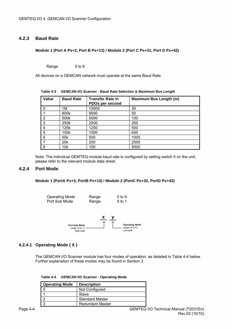
4.2.3 Baud Rate
Module 1 (Port A Px+2, Port B Px+13) / Module 2 (Port C Px+31, Port D Px+42)
Range 0 to 8
All devices on a GEMCAN network must operate at the same Baud Rate.
Table 4-3 GEMCAN I/O Scanner - Baud Rate Selection & Maximum Bus Length
Value Baud Rate Transfer Rate in PDOs per second
Maximum Bus Length (m)
0 1M 10000 30 1 800k 8000 50 2 500k 5000 100 3 250k 2500 250 4 125k 1250 500 5 100k 1000 650 6 50k 500 1000 7 20k 200 2500 8 10k 100 5000
Note: The individual GEMTEQ module baud rate is configured by setting switch 5 on the unit, please refer to the relevant module data sheet.
4.2.4 Port Mode
Module 1 (PortA Px+3, PortB Px+14) / Module 2 (PortC Px+32, PortD Px+43)
Operating Mode Range 0 to 4 Port Sub Mode Range 0 to 1
xPort Sub Mode
range (0 to 1)High byte
Operating Moderange (0 to 4)Low byte
y
4.2.4.1 Operating Mode ( X )
The GEMCAN I/O Scanner module has four modes of operation, as detailed in Table 4-4 below. Further explanation of these modes may be found in Section 3.
Table 4-4 GEMCAN I/O Scanner - Operating Mode
GEMTEQ I/O Technical Manual (T2031En) Page 4-4
Operating Mode Description 0 Not Configured 1 Slave 2 Standard Master 3 Redundant Master
Rev.02 (10/10)
GEMTEQ I/O 4. GEMCAN I/O Scanner Configuration
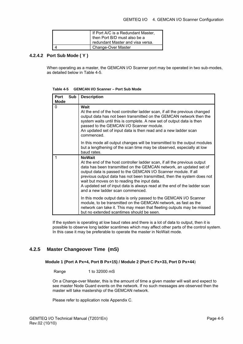
If Port A/C is a Redundant Master, then Port B/D must also be a redundant Master and visa versa.
4 Change-Over Master
4.2.4.2 Port Sub Mode ( Y )
When operating as a master, the GEMCAN I/O Scanner port may be operated in two sub-modes, as detailed below in Table 4-5.
Table 4-5 GEMCAN I/O Scanner – Port Sub Mode
Port Sub Mode
Description
0 Wait At the end of the host controller ladder scan, if all the previous changed output data has not been transmitted on the GEMCAN network then the system waits until this is complete. A new set of output data is then passed to the GEMCAN I/O Scanner module. An updated set of input data is then read and a new ladder scan commenced.
In this mode all output changes will be transmitted to the output modules but a lengthening of the scan time may be observed, especially at low baud rates.
1 NoWait At the end of the host controller ladder scan, if all the previous output data has been transmitted on the GEMCAN network, an updated set of output data is passed to the GEMCAN I/O Scanner module. If all previous output data has not been transmitted, then the system does not wait but moves on to reading the input data. A updated set of input data is always read at the end of the ladder scan and a new ladder scan commenced.
In this mode output data is only passed to the GEMCAN I/O Scanner module, to be transmitted on the GEMCAN network, as fast as the network can take it. This may mean that fleeting outputs may be missed but no extended scantimes should be seen.
If the system is operating at low baud rates and there is a lot of data to output, then it is possible to observe long ladder scantimes which may affect other parts of the control system. In this case it may be preferable to operate the master in NoWait mode.
4.2.5 Master Changeover Time (mS)
Module 1 (Port A Px+4, Port B Px+15) / Module 2 (Port C Px+33, Port D Px+44)
Range 1 to 32000 mS
On a Change-over Master, this is the amount of time a given master will wait and expect to see master Node Guard events on the network. If no such messages are observed then the master will take mastership of the GEMCAN network.
Please refer to application note Appendix C.
GEMTEQ I/O Technical Manual (T2031En) Rev.02 (10/10)
Page 4-5
GEMTEQ I/O 4. GEMCAN I/O Scanner Configuration
4.2.6 Maximum Input Delay Time (mS)
Module 1 (Port A Px+5, Port B Px+16) / Module 2 (Port C Px+34, Port D Px+45)
Range 1 to 32000 mS 0 = 500 mS (Default)
If after the Maximum Input Delay Time, the GEMCAN I/O Scanner has not received a new set of data from an input device, an update of data will be requested; as long as the device is known to exist on the network.
This parameter has no operation if the GEMCAN I/O Scanner Port is configured as a Slave.
4.2.7 Maximum Output Delay Time (mS)
Module 1 (Port A Px+6, Port B Px+17) / Module 2 (Port C Px+35, Port D Px+46)
Range 1 to 32000 mS 0 = 500 mS (Default)
If after the Maximum Output Delay Time, the GEMCAN I/O Scanner has not received a change in data from the host controller for a given device, an update of data will be transmitted; as long as the device is known to exist on the network.
4.2.8 Split Offset
Module 1 (Port A Px+7, Port B Px+18) / Module 2 (Port C Px+36, Port D Px+47)
Range 1 to 125
This parameter has no action for Port A/C and should be set to zero. The parameter defines the split between which Node IDs will operate on Port A/C and which Nodes IDs will operate on Port B/D of the GEMCAN I/O Scanner module.
e.g. If Px+18 = 50 then
Port A will exchange data with Nodes 1 to 49 Port B will exchange data with Nodes 50 to 125
4.2.9 Sync Period (mS)
Module 1 (Port A Px+8, Port B Px+19) / Module 2 (Port C Px+37, Port D Px+48)
Range 1 to 32000 mS
Any non-zero value in this parameter will cause the Master to send a Synchronisation message on the CAN network at the interval specified (not used for future use).
GEMTEQ I/O Technical Manual (T2031En) Page 4-6 Rev.02 (10/10)
GEMTEQ I/O 4. GEMCAN I/O Scanner Configuration
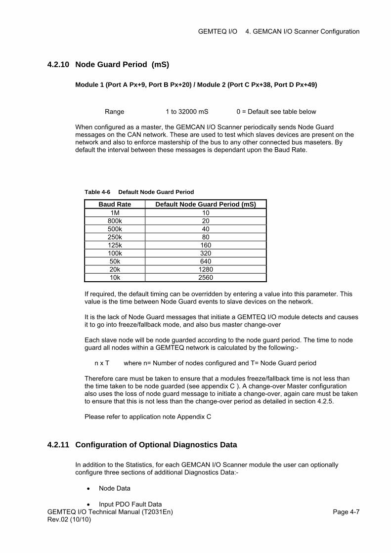
4.2.10 Node Guard Period (mS)
Module 1 (Port A Px+9, Port B Px+20) / Module 2 (Port C Px+38, Port D Px+49)
Range 1 to 32000 mS 0 = Default see table below
When configured as a master, the GEMCAN I/O Scanner periodically sends Node Guard messages on the CAN network. These are used to test which slaves devices are present on the network and also to enforce mastership of the bus to any other connected bus maseters. By default the interval between these messages is dependant upon the Baud Rate.
Table 4-6 Default Node Guard Period
Baud Rate Default Node Guard Period (mS) 1M 10
800k 20 500k 40 250k 80 125k 160 100k 320 50k 640 20k 1280 10k 2560
If required, the default timing can be overridden by entering a value into this parameter. This value is the time between Node Guard events to slave devices on the network.
It is the lack of Node Guard messages that initiate a GEMTEQ I/O module detects and causes it to go into freeze/fallback mode, and also bus master change-over
Each slave node will be node guarded according to the node guard period. The time to node guard all nodes within a GEMTEQ network is calculated by the following:-
n x T where n= Number of nodes configured and T= Node Guard period
Therefore care must be taken to ensure that a modules freeze/fallback time is not less than the time taken to be node guarded (see appendix C ). A change-over Master configuration also uses the loss of node guard message to initiate a change-over, again care must be taken to ensure that this is not less than the change-over period as detailed in section 4.2.5.
Please refer to application note Appendix C
4.2.11 Configuration of Optional Diagnostics Data
In addition to the Statistics, for each GEMCAN I/O Scanner module the user can optionally configure three sections of additional Diagnostics Data:-
• Node Data
GEMTEQ I/O Technical Manual (T2031En) Rev.02 (10/10)
Page 4-7• Input PDO Fault Data
GEMTEQ I/O 4. GEMCAN I/O Scanner Configuration
• Output PDO Fault Data
For each section of Diagnostics data, the first configuration word gives the Data Table letter (A .. W) and the second configuration word the offset within the Data Table, of where the Diagnostics data is to be placed.
e.g. If Px+23 = ‘G’ (71 dec, @47 hex) and Px+24 = 400, then the Node Data for Module 1 would be placed in G400 onwards.
If Px+25 = ‘G’ (71 dec, @47 hex) and Px+26 = 500, then the Input PDO fault Data for Module 1 would be placed in G500 onwards.
If Px+27 = ‘H’ (72 dec, @48 hex) and Px+28 = 400, then the Output PDO fault Data for Module 1 would be placed in H400 onwards.
4.2.11.1 Node Data
Module 1 ( Px+23 and Px+24) / Module 2 ( Px+52 and Px+53)
One word should be allocated per slave device. This contains the module type located at the Node ID. Further details can be found in Section 8.3.1
4.2.11.2 Input PDO Fault Data
Module 1 ( Px+25 and Px+26) / Module 2 ( Px+54 and Px+55)
Each slave device should be allocated two words of Input PDO Fault Data. Further details can be found in Section 8.3.2.
4.2.11.3 Output PDO Fault Data
Module 1 ( Px+27 and Px+28) / Module 2 ( Px+56 and Px+57)
Each slave device should be allocated two words of Output PDO Fault Data. Further details can be found in Section 8.3.3.
GEMTEQ I/O Technical Manual (T2031En) Page 4-8 Rev.02 (10/10)
GEMTEQ I/O 5. GEMCAN SPECIAL FUNCTION
5. GEMCAN SPECIAL FUNCTION
5.1 INTRODUCTION The application interface to the GEMCAN I/O Scanner consists of P-Table configuration data and a Special Function: CANCMD (T114). This function is only required when operating the GEMCAN network with Masters operating in Change-over mode. The Special Function validates the parameters supplied by the user and writes a report in the function Status Word and Q rung output. If errors are detected during the validation phase, no further action is performed by the Special Function and bit 15 of the Status Word and Q rung output are set. If no errors are detected the request is passed to the appropriate GEMCAN I/O Scanner module and the Status Word and Q rung output updated. The GEMCAN I/O Scanner module actions the request. The result of the request may be found by monitoring the respective Statistics in the F-Tables.
WARNING
When using this software, the user program must include the correct use of the diagnostic data to ensure that the data exchanged is valid, error-free and current.
GEMTEQ I/O Technical Manual (T2031En) Rev.02 (10/10)
Page 5-1
GEMTEQ I/O 5. GEMCAN SPECIAL FUNCTION
5.2 T114 CANCMD SPECIAL FUNCTION
The CANCMD Special Function requests a Change-over Master to Release or Request mastership of a GEMCAN Network.
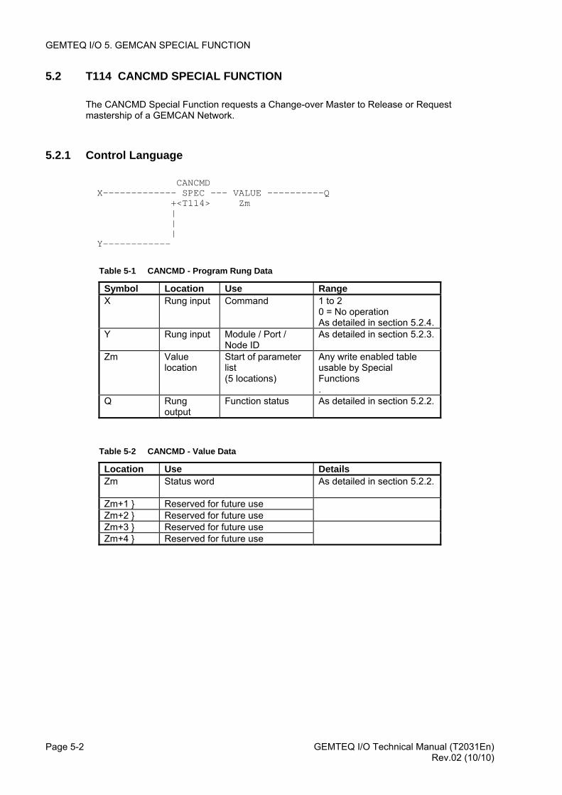
5.2.1 Control Language
CANCMD X------------- SPEC --- VALUE ----------Q +<T114> Zm | | | Y------------
Table 5-1 CANCMD - Program Rung Data
Symbol Location Use Range X
Rung input Command 1 to 2 0 = No operation As detailed in section 5.2.4.
Y Rung input Module / Port / Node ID
As detailed in section 5.2.3.
Zm Value location
Start of parameter list (5 locations)
Any write enabled table usable by Special Functions .
Q Rung output
Function status As detailed in section 5.2.2.
Table 5-2 CANCMD - Value Data
Location Use Details Zm
Status word As detailed in section 5.2.2.
Zm+1 } Reserved for future use Zm+2 } Reserved for future use Zm+3 } Reserved for future use Zm+4 } Reserved for future use
GEMTEQ I/O Technical Manual (T2031En) Page 5-2 Rev.02 (10/10)
GEMTEQ I/O 5. GEMCAN SPECIAL FUNCTION
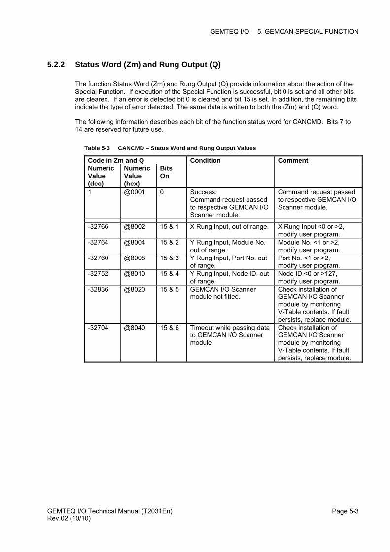
5.2.2 Status Word (Zm) and Rung Output (Q)
The function Status Word (Zm) and Rung Output (Q) provide information about the action of the Special Function. If execution of the Special Function is successful, bit 0 is set and all other bits are cleared. If an error is detected bit 0 is cleared and bit 15 is set. In addition, the remaining bits indicate the type of error detected. The same data is written to both the (Zm) and (Q) word. The following information describes each bit of the function status word for CANCMD. Bits 7 to 14 are reserved for future use.
Table 5-3 CANCMD – Status Word and Rung Output Values
Code in Zm and Q Condition Comment Numeric Value (dec)
Numeric Value (hex)
Bits On
1 @0001 0 Success. Command request passed to respective GEMCAN I/O Scanner module.
Command request passed to respective GEMCAN I/O Scanner module.
-32766 @8002 15 & 1 X Rung Input, out of range. X Rung Input <0 or >2, modify user program.
-32764 @8004 15 & 2 Y Rung Input, Module No. out of range.
Module No. <1 or >2, modify user program.
-32760 @8008 15 & 3 Y Rung Input, Port No. out of range.
Port No. <1 or >2, modify user program.
-32752 @8010 15 & 4 Y Rung Input, Node ID. out of range.
Node ID <0 or >127, modify user program.
-32836 @8020 15 & 5 GEMCAN I/O Scanner module not fitted.
Check installation of GEMCAN I/O Scanner module by monitoring V-Table contents. If fault persists, replace module.
-32704 @8040 15 & 6 Timeout while passing data to GEMCAN I/O Scanner module
Check installation of GEMCAN I/O Scanner module by monitoring V-Table contents. If fault persists, replace module.
GEMTEQ I/O Technical Manual (T2031En) Rev.02 (10/10)
Page 5-3
GEMTEQ I/O 5. GEMCAN SPECIAL FUNCTION
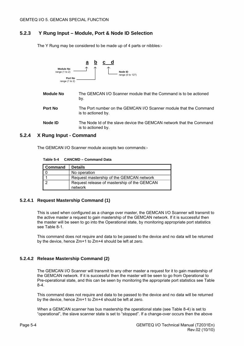
5.2.3 Y Rung Input – Module, Port & Node ID Selection
The Y Rung may be considered to be made up of 4 parts or nibbles:-
a b c dModule No
range (1 to 2)
Port Norange (1 to 2)
Node IDrange (0 to 127)
Module No The GEMCAN I/O Scanner module that the Command is to be actioned by.
Port No The Port number on the GEMCAN I/O Scanner module that the Command is to actioned by.
Node ID The Node Id of the slave device the GEMCAN network that the Command is to actioned by.
5.2.4 X Rung Input - Command
The GEMCAN I/O Scanner module accepts two commands:-
Table 5-4 CANCMD – Command Data
Command Details 0 No operation 1 Request mastership of the GEMCAN network 2 Request release of mastership of the GEMCAN
network
5.2.4.1 Request Mastership Command (1)
This is used when configured as a change over master, the GEMCAN I/O Scanner will transmit to the active master a request to gain mastership of the GEMCAN network. If it is successful then the master will be seen to go into the Operational state, by monitoring appropriate port statistics see Table 8-1.
This command does not require and data to be passed to the device and no data will be returned by the device, hence Zm+1 to Zm+4 should be left at zero.
5.2.4.2 Release Mastership Command (2)
The GEMCAN I/O Scanner will transmit to any other master a request for it to gain mastership of the GEMCAN network. If it is successful then the master will be seen to go from Operational to Pre-operational state, and this can be seen by monitoring the appropriate port statistics see Table 8-4.
This command does not require and data to be passed to the device and no data will be returned by the device, hence Zm+1 to Zm+4 should be left at zero.
When a GEMCAN scanner has bus mastership the operational state (see Table 8-4) is set to “operational”, the slave scanner state is set to “stopped”. If a change-over occurs then the above
GEMTEQ I/O Technical Manual (T2031En) Page 5-4 Rev.02 (10/10)

GEMTEQ I/O 5. GEMCAN SPECIAL FUNCTION
states are reversed. To detect which unit is bus master the operational state can be monitored within the ladder program.
GEMTEQ I/O Technical Manual (T2031En) Rev.02 (10/10)
Page 5-5

GEMTEQ I/O 6. GEMTEQ I/O Modules
6. GEMTEQ I/O MODULES
6.1 INTRODUCTION
This section describes the GEMTEQ I/O modules in more detail than can be found in their respective Instruction Sheets. Details of the module configuration data, comprehensive fault finding and diagnostics information, as well as connection details are given.
6.2 GEMTEQ I/O MODULES
The GEMTEQ range of I/O presently consists of the following types of I/O module:-
Table 6-1 GEMTEQ I/O Modules
Order Code Description 9730-4012 24V d.c., 16 way Input Module, Normal/Inverse Logic 9731-4012 24V d.c, 0.5A, 16 way Output Module 9732-4012 110V a.c., 16 way Input Module 9733-4012 110V a.c, 1A, 16 way Output Module 9734-4012 8 Input / 8 Output Combination Analogue Module 9735-4012 Relay, 3A, 16 way Output Module 9736-4012 4 Channel Counter Module 9737-4012 16 Input / 8 Output Combination Analogue Module
6.2.1 24 V d.c 16-way Input Module, Normal/Inverse Logic (9730)
For a complete technical specification, please refer to the Instruction Sheet T1981En.
6.2.2 24 V d.c., 0.5A, 16-way Output Module (9731)
For a complete technical specification, please refer to the Instruction Sheet T1982En.
6.2.3 110 V a.c. 16-way Input Module (9732)
For a complete technical specification, please refer to the Instruction Sheet T1983En.
GEMTEQ I/O Technical Manual (T2031En) Rev.02 (10/10)
Page 6-1
GEMTEQ I/O 6. GEMTEQ I/O Modules
6.2.4 110 V a.c., 1A, 16-way Output Module (9733)
For a complete technical specification, please refer to the Instruction Sheet T1984En.
6.2.5 8 In / 8 Out Combination Analogue Module (9734)
For a complete technical specification, please refer to the Instruction Sheet T1985En.
6.2.6 Relay, 3A, 16-way Output Module (9735)
For a complete technical specification, please refer to the Instruction Sheet T1986En.
6.2.7 4 Channel Counter Module (9736)
For a complete technical specification, please refer to the Instruction Sheet T1995En.
6.2.8 16 Input / 8 Output Combination Analogue Module (9737)
For a complete technical specification, please refer to the Instruction T2113En.
GEMTEQ I/O Technical Manual (T2031En) Page 6-2 Rev.02 (10/10)
GEMTEQ I/O 6. GEMTEQ I/O Modules
6.3 MODULE CONFIGURATION
Before a GEMTEQ I/O module may be connected to the GEMCAN network, the following two items must be setup on the module.
• Node ID
• Baud Rate
6.3.1 Node ID
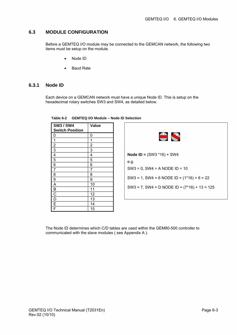
Each device on a GEMCAN network must have a unique Node ID. This is setup on the hexadecimal rotary switches SW3 and SW4, as detailed below.
Table 6-2 GEMTEQ I/O Module – Node ID Selection
SW3 / SW4 Switch Position
Value
0 0 1 1 2 2 3 3 4 4 5 5 6 6 7 7 8 8 9 9 A 10 B 11 C 12 D 13 E 14 F 15
SW3 = 7, SW4 = D NODE ID = (7*16) + 13 = 125
SW3 = 1, SW4 = 6 NODE ID = (1*16) + 6 = 22
SW3 = 0, SW4 = A NODE ID = 10
e.g.
Node ID = (SW3 *16) + SW4
The Node ID determines which C/D tables are used within the GEM80-500 controller to communicated with the slave modules ( see Appendix A ).
GEMTEQ I/O Technical Manual (T2031En) Rev.02 (10/10)
Page 6-3
GEMTEQ I/O 6. GEMTEQ I/O Modules
6.3.2 Baud Rate
The baud rate is selected by the hexadecimal rotary switch SW5, see Table 6-3. All devices on a GEMCAN network should have the same Baud Rate selection.
Table 6-3 GEMTEQ I/O Module - Baud Rate Selection
Value Baud Rate Maximum Bus Length (m) 0 1M 30 1 800k 50 2 500k 100 3 250k 250 4 125k 500 5 100k 650 6 50k 1000 7 20k 2500 8 10k 5000
6.4 CONNECTIONS
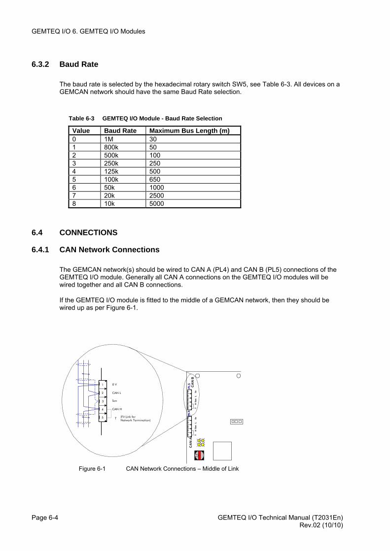
6.4.1 CAN Network Connections
The GEMCAN network(s) should be wired to CAN A (PL4) and CAN B (PL5) connections of the GEMTEQ I/O module. Generally all CAN A connections on the GEMTEQ I/O modules will be wired together and all CAN B connections.
If the GEMTEQ I/O module is fitted to the middle of a GEMCAN network, then they should be wired up as per Figure 6-1.
0 V
CAN L
Scn
CAN H
(Fit Link forNetwork Termination)
1
2
3
4
5
CA
N B
CA
N A
TH
L0v
Scn
TH
L0v
Scn
PL4
PL5
GEMTEQ I/O Technical Manual (T2031En) Page 6-4
4
T
Figure 6-1 CAN Network Connections – Middle of Link
Rev.02 (10/10)
GEMTEQ I/O 6. GEMTEQ I/O Modules
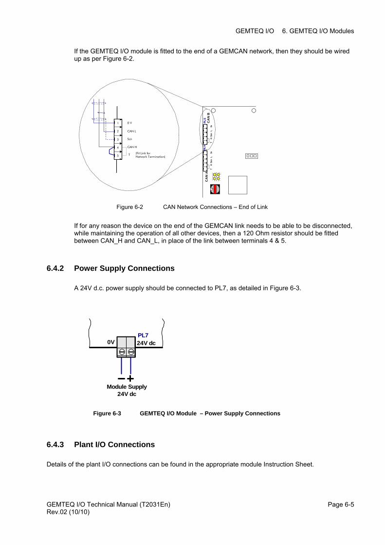
If the GEMTEQ I/O module is fitted to the end of a GEMCAN network, then they should be wired up as per Figure 6-2.
0 V
CAN L
Scn
CAN H
(Fit Link forNetwork Termination)
1
2
3
4
5
CA
N B
CA
N A
TH
L0v
Scn
TH
L0v
Scn
PL4
PL5
GEMTEQ I/O Technical Manual (T2031En) Rev.02 (10/10)
Page 6-5
4
T
Figure 6-2 CAN Network Connections – End of Link
If for any reason the device on the end of the GEMCAN link needs to be able to be disconnected, while maintaining the operation of all other devices, then a 120 Ohm resistor should be fitted between CAN_H and CAN_L, in place of the link between terminals 4 & 5.
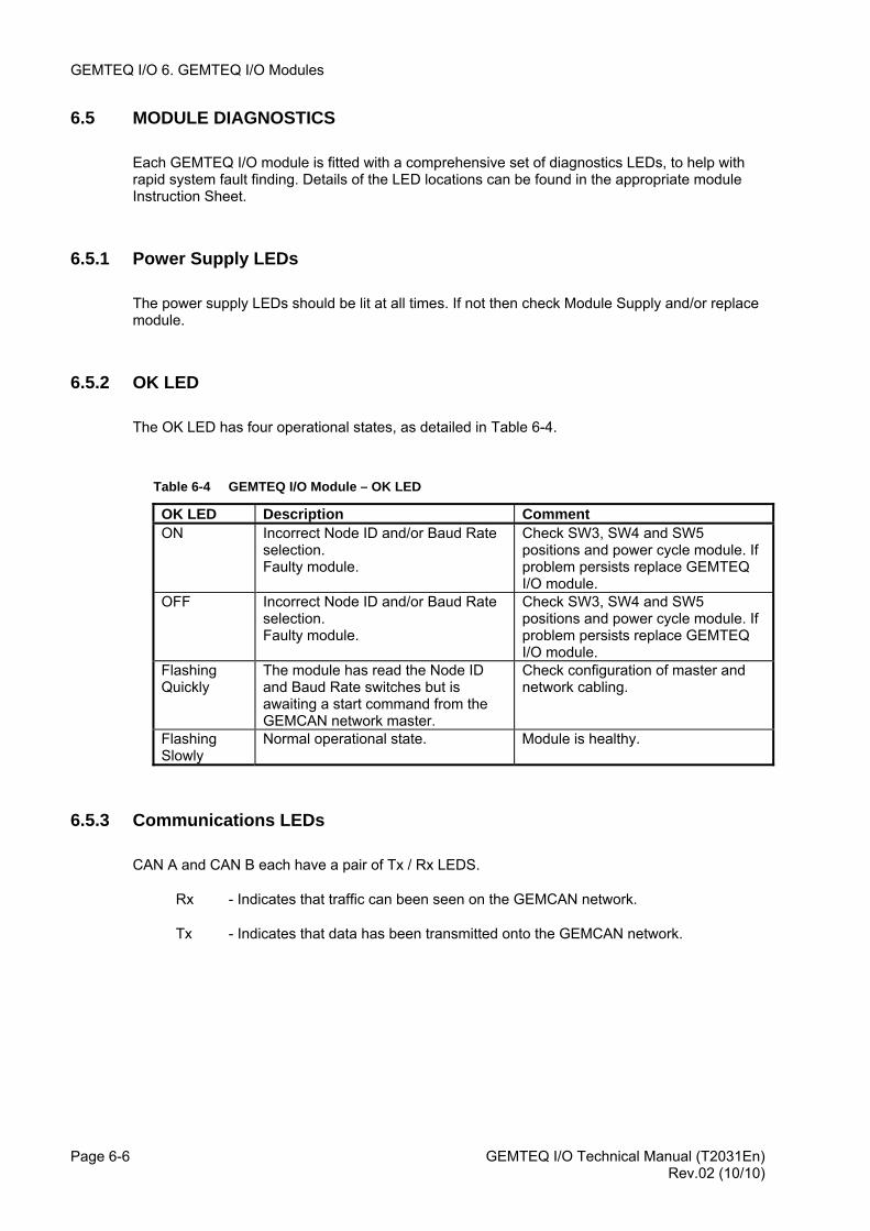
6.4.2 Power Supply Connections
A 24V d.c. power supply should be connected to PL7, as detailed in Figure 6-3.
24V dc0VPL7
Module Supply24V dc
Figure 6-3 GEMTEQ I/O Module – Power Supply Connections
6.4.3 Plant I/O Connections
Details of the plant I/O connections can be found in the appropriate module Instruction Sheet.
GEMTEQ I/O 6. GEMTEQ I/O Modules
6.5 MODULE DIAGNOSTICS
Each GEMTEQ I/O module is fitted with a comprehensive set of diagnostics LEDs, to help with rapid system fault finding. Details of the LED locations can be found in the appropriate module Instruction Sheet.
6.5.1 Power Supply LEDs
The power supply LEDs should be lit at all times. If not then check Module Supply and/or replace module.
6.5.2 OK LED
The OK LED has four operational states, as detailed in Table 6-4.
Table 6-4 GEMTEQ I/O Module – OK LED
OK LED Description Comment ON Incorrect Node ID and/or Baud Rate
selection. Faulty module.
Check SW3, SW4 and SW5 positions and power cycle module. If problem persists replace GEMTEQ I/O module.
OFF Incorrect Node ID and/or Baud Rate selection. Faulty module.
Check SW3, SW4 and SW5 positions and power cycle module. If problem persists replace GEMTEQ I/O module.
Flashing Quickly
The module has read the Node ID and Baud Rate switches but is awaiting a start command from the GEMCAN network master.
Check configuration of master and network cabling.
Flashing Slowly
Normal operational state. Module is healthy.
6.5.3 Communications LEDs
CAN A and CAN B each have a pair of Tx / Rx LEDS.
Rx - Indicates that traffic can been seen on the GEMCAN network.
Tx - Indicates that data has been transmitted onto the GEMCAN network.
GEMTEQ I/O Technical Manual (T2031En) Page 6-6 Rev.02 (10/10)
GEMTEQ I/O 6. GEMTEQ I/O Modules
6.6 APPLICATION CONFIGURATION DATA
GEMTEQ modules can be configured by the application code within the GEM80-500 Controller.
Configuration data is sent to an individual module using the appropriate "D" table for that module. This is achieved by transmitting data to the GEMTEQ I/O module via the GEMCAN network using an output PDO.
The following details the options available:
• Input Filter Time
• PDO Silence Time
• Freeze/Fallback Strategy
The available configuration options for a particular module are described in the modules data sheets.
For example a digital output module has a freeze/fallback option but no input filter time, whereas an input module has an input filter time but no freeze fallback data.
6.6.1 Input Filter Time
Range 1 to 32000 mS
Each input module has a hardware filter time. If the application requires it, additional software filtering may be implemented by transmitting a non zero value in the Input Filter Time. For further details please refer to the appropriate Instruction Sheet.
6.6.2 PDO Silence Time
Range 1 to 32000 mS 0 = 20 mS (Default)
Each time an input changes state, the GEMTEQ Input module will report this input value to the master. Hence if a digital input is ‘chattering’ or an analogue input has a lot of noise on it, then a lot of network traffic will take place to report these changing values. The input module may be configured to only report changes every X ms by transmitting the value X to the input module in the PDO Silence Time. For further details please refer to the appropriate Instruction Sheet.
6.6.3 Freeze/Fallback
A GEMTEQ Output module detects Node Guard messages on the GEMCAN Network. If the module does not see these messages for the Freeze/Fallback Timeout period, see section 6.6.3.1, then the module will adopt Freeze/Fallback as defined by the Freeze/Fallback Value, see section 6.6.3.2.
See application note Appendix C.
GEMTEQ I/O Technical Manual (T2031En) Rev.02 (10/10)
Page 6-7
GEMTEQ I/O 6. GEMTEQ I/O Modules
6.6.3.1 Freeze/Fallback Timeout (mS)
Range 1 to 32000 mS 0 = 500 mS (Default)
If the application requires the default freeze/fallback time to be overridden then a value can be transmitted to the module in the Freeze/Fallback Time. For further details please refer to the appropriate Instruction Sheet.
6.6.3.2 Freeze/Fallback Value
By using one bit per channel (Bit 0 = Channel 0), this signifies whether freeze or fallback should be adopted, when loss of Node Guard messages has been detected by the I/O module.
0 Fallback to zero
1 Freeze present value
For further details please refer to the appropriate Instruction Sheet.
6.6.4 Analog Input – Voltage or Current Input Mode
By using one bit per channel (Bit 0 = Channel 0), this signifies whether the Analog I/P channel should operate as Voltage or Current input mode.
0 Voltage Input mode
1 Current Input mode
6.6.5 Analog Input – 0-20mA or 4-20mA Input Mode
By using one bit per channel (Bit 0 = Channel 0), this signifies whether the Analog I/P channel, when configured in Current input mode, should operate as 0 to 20mA or 4 to 20mA.
0 0 to 20mA input mode
1 4 to 20mA input mode
GEMTEQ I/O Technical Manual (T2031En) Page 6-8 Rev.02 (10/10)
GEMTEQ I/O 7. Installation and Commissioning
7. INSTALLATION AND COMMISSIONING
Do not use mobile phones or walkie talkies within 2 metres (6 feet) of the equipment.
Radio Transmitters
WARNING
CAUTION
This equipment contains solid state devices which may be affected by electrostatic discharge. Observe static handling precautions.
7.1 INTRODUCTION
This section describes the receipt of the GEMTEQ I/O modules at a site and provides instructions for their installation and commissioning. For details of the installation of the GEMCAN I/O Scanner module in the host GEM80 controller, please refer to the respective controller Technical Manual.
7.1.1 Unpacking and Checking the Consignment
When the equipment arrives on site it should be carefully unpacked and inspected for any sign of damage. Handling precautions for equipment containing Electrostatic Sensitive Devices (ESD) should be followed.
The complete consignment should be checked against the delivery note for any loss in transit.
7.1.2 What to do if something is missing or damaged
If any damage has occurred, or any parts are missing, CONVERTEAM Kidsgrove, should be contacted immediately and the following details quoted:
(1) List of damaged or missing items;
(2) Description of any damage;
(3) Package numbers;
(4) Delivery/Advice Note numbers, dates and any other reference numbers such as order and item numbers.
Note:
Failure to inform CONVERTEAM Kidsgrove, of damage to goods or shortages within three days from receipt of equipment will be held to free Converteam from liability.
GEMTEQ I/O Technical Manual (T2031En) Page 7-1Rev.02 (10/10)

GEMTEQ I/O 7. Installation and Commissioning
7.2 STORING GEM80 EQUIPMENT BEFORE INSTALLATION
7.2.1 Environmental Conditions and Protection
Equipment which is not required for immediate installation should be stored in a clean, dry atmosphere at a reasonably constant temperature (-20 to +70°C). To minimise the ingress of fine dust, the equipment should be kept in the original packing, which should be re-sealed after the delivery inspection.
Where equipment is unavoidably subjected to high humidity (e.g. for short pre-commissioning periods during installation in a humid location) it is recommended that any enclosure, into which the controller is to be mounted, should be fitted with anti-condensation heaters and the equipment be thoroughly dried out prior to the first application of power. Such heaters should then be automatically switched on whenever the GEM 80 equipment is subsequently shut down.
7.3 SITE REQUIREMENTS
The area in which the GEM80 equipment is to be installed must meet the following conditions:
(a) Comply with the Environmental Specification
(b) Have adequate access for installation, commissioning and maintenance.
7.3.1 Protection of Equipment from Static Damage
Protective measures are required when handling any of the optional modules to prevent damage to Electrostatic Sensitive Devices (ESDs). The following rules must be observed:
(a) Personnel handling the modules should NOT wear outer clothing which will generate a static charge, e.g. synthetic materials like nylon, cotton is preferable.
(b) All personnel handling the modules should put themselves in contact with a grounded surface before removing any modules from their protective packing or from equipment. The antistatic equipment should be kept on during all module handling.
(c) Avoid finger contact with devices on the modules and with its connectors
(d) If it is necessary to place any module down 'unprotected', place on a static shielding bag, or other equivalent material
(e) Modules should be protected by a static-shielding bag when out of the equipment.
GEMTEQ I/O Technical Manual (T2031En) Page 7-2 Rev.02 (10/10)

GEMTEQ I/O 7. Installation and Commissioning
7.4 COMMISSIONING GUIDANCE
The GEMCAN I/O Scanner and GEMTEQ I/O will have to be configured to meet particular application requirements. Because these requirements vary for each GEM80 application this section of the manual only includes general commissioning guidance about the method to be followed. The instructions required for each application should be discussed with CONVERTEAM or an approved System Builder.
7.4.1 Preparation
Before starting to commission a GEM 80 system, you should already have:
(a) Installed the equipment and cabled it up, including all earth (ground) connections as given in this section;
(b) Cabled up the watchdog and safety circuits in accordance with the guidelines given in this section and checked their operation;
(c) A suitable GEM80 Programming Package with a stock of suitable storage media;
(d) Ensured that all pertinent regulations for earthing/grounding of the equipment have been adhered to.
7.4.2 Documents Required
During commissioning the following documents will be required in addition to this manual:
(a) A User/Technical Manual for the particular GEM 80 Programming Package in use;
(b) 'GEM 80 Ladder Diagram Programming Manual', Publication No.T300;
These documents will enable test programs to be written to check out the equipment.
7.4.3 Handling Precautions During Setting Up of Equipment
The following precautions must be taken during testing/setting up operations on equipment containing printed circuit boards (PCBs) with Electrostatic Sensitive Devices (ESDs):
(a) All test equipment must be grounded to a common earth point;
(b) The system power and test equipment must be switched OFF before making or breaking any connections;
(c) When possible, power supply voltages should be applied before signal inputs, and should be maintained until signal inputs are removed;
(d) Dielectric strength and insulation resistance tests should not be carried out with the PCBs installed in the equipment;
(e) Do not use audible continuity tests on PCBs;
(f) Do not use 'Freeze' Aerosols on PCBs.
GEMTEQ I/O Technical Manual (T2031En) Page 7-3Rev.02 (10/10)
GEMTEQ I/O 7. Installation and Commissioning
7.4.4 Radio Frequency Interference (RFI)
This clause is intended as a guide for users who wish to operate GEM80 equipment in the vicinity of a radio transmitter. The transmitter may be of the static or the hand-held portable type. Unrestricted use of a transmitting device could result in a malfunction of the equipment. This in turn could cause a breakdown of plant equipment and injury to personnel. GEM80 equipment is designed to function satisfactorily within a RFI field strength of 10V/m over a frequency range of 30 MHz to 1 GHz.
GEMTEQ I/O Technical Manual (T2031En) Page 7-4 Rev.02 (10/10)
GEMTEQ I/O 8. Maintenance and Fault Finding
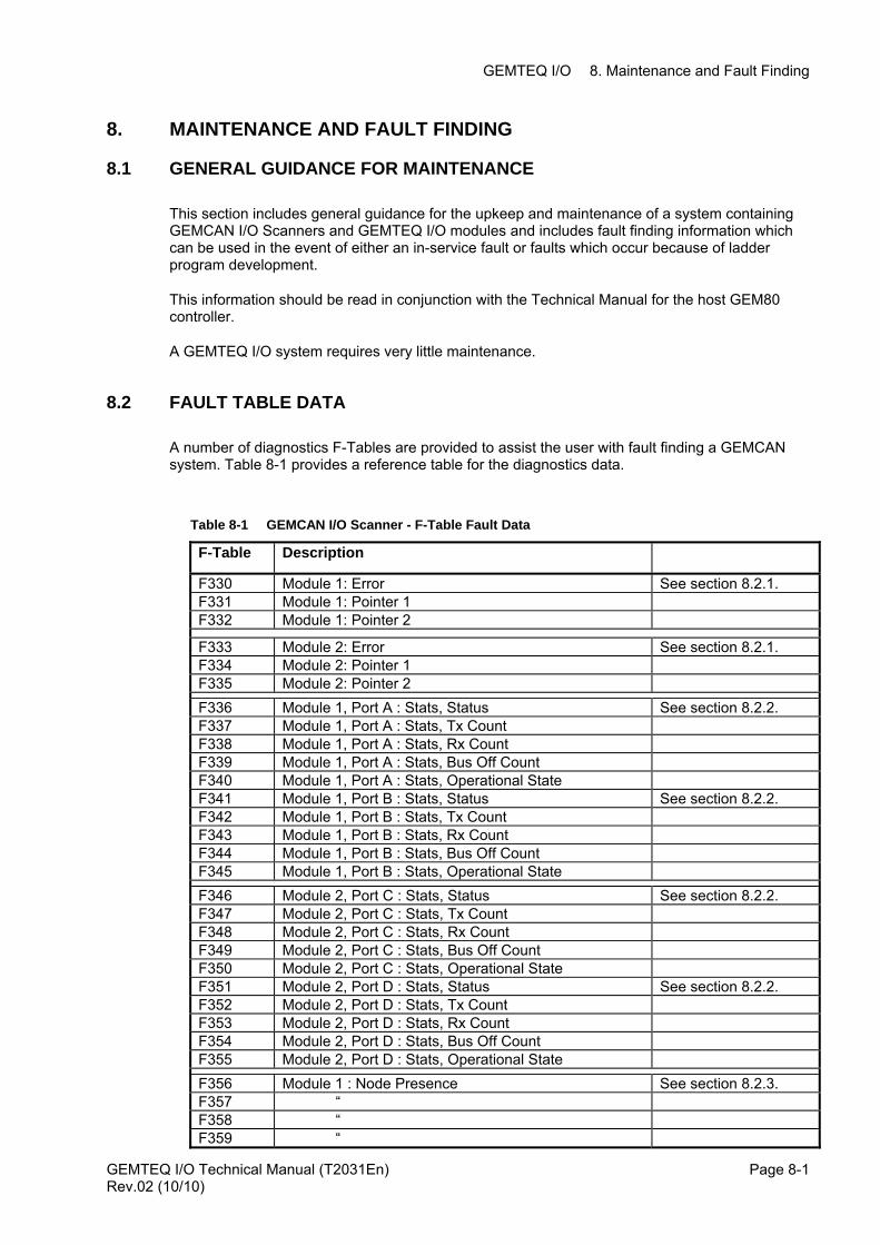
8. MAINTENANCE AND FAULT FINDING
8.1 GENERAL GUIDANCE FOR MAINTENANCE
This section includes general guidance for the upkeep and maintenance of a system containing GEMCAN I/O Scanners and GEMTEQ I/O modules and includes fault finding information which can be used in the event of either an in-service fault or faults which occur because of ladder program development.
This information should be read in conjunction with the Technical Manual for the host GEM80 controller.
A GEMTEQ I/O system requires very little maintenance.
8.2 FAULT TABLE DATA
A number of diagnostics F-Tables are provided to assist the user with fault finding a GEMCAN system. Table 8-1 provides a reference table for the diagnostics data.
Table 8-1 GEMCAN I/O Scanner - F-Table Fault Data
F-Table Description F330 Module 1: Error See section 8.2.1. F331 Module 1: Pointer 1 F332 Module 1: Pointer 2
F333 Module 2: Error See section 8.2.1. F334 Module 2: Pointer 1 F335 Module 2: Pointer 2 F336 Module 1, Port A : Stats, Status See section 8.2.2. F337 Module 1, Port A : Stats, Tx Count F338 Module 1, Port A : Stats, Rx Count F339 Module 1, Port A : Stats, Bus Off Count F340 Module 1, Port A : Stats, Operational State F341 Module 1, Port B : Stats, Status See section 8.2.2. F342 Module 1, Port B : Stats, Tx Count F343 Module 1, Port B : Stats, Rx Count F344 Module 1, Port B : Stats, Bus Off Count F345 Module 1, Port B : Stats, Operational State F346 Module 2, Port C : Stats, Status See section 8.2.2. F347 Module 2, Port C : Stats, Tx Count F348 Module 2, Port C : Stats, Rx Count F349 Module 2, Port C : Stats, Bus Off Count F350 Module 2, Port C : Stats, Operational State F351 Module 2, Port D : Stats, Status See section 8.2.2. F352 Module 2, Port D : Stats, Tx Count F353 Module 2, Port D : Stats, Rx Count F354 Module 2, Port D : Stats, Bus Off Count F355 Module 2, Port D : Stats, Operational State F356 Module 1 : Node Presence See section 8.2.3. F357 “ F358 “ F359 “
GEMTEQ I/O Technical Manual (T2031En) Page 8-1Rev.02 (10/10)
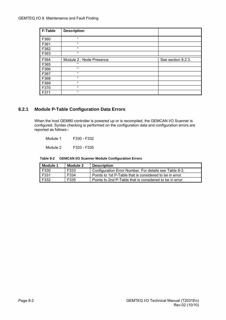
GEMTEQ I/O 8. Maintenance and Fault Finding
GEMTEQ I/O Technical Manual (T2031En) Page 8-2
F-Table Description
F360 “ F361 “ F362 “ F363 “ F364 Module 2 : Node Presence See section 8.2.3. F365 “ F366 “ F367 “ F368 “ F369 “ F370 “ F371 “
8.2.1 Module P-Table Configuration Data Errors
When the host GEM80 controller is powered up or is recompiled, the GEMCAN I/O Scanner is configured. Syntax checking is performed on the configuration data and configuration errors are reported as follows:-
Module 1 F330 - F332
Module 2 F333 - F335
Table 8-2 GEMCAN I/O Scanner Module Configuration Errors
Module 1 Module 2 Description F330 F333 Configuration Error Number. For details see Table 8-3. F331 F334 Points to 1st P-Table that is considered to be in error. F332 F335 Points to 2nd P-Table that is considered to be in error.
Rev.02 (10/10)
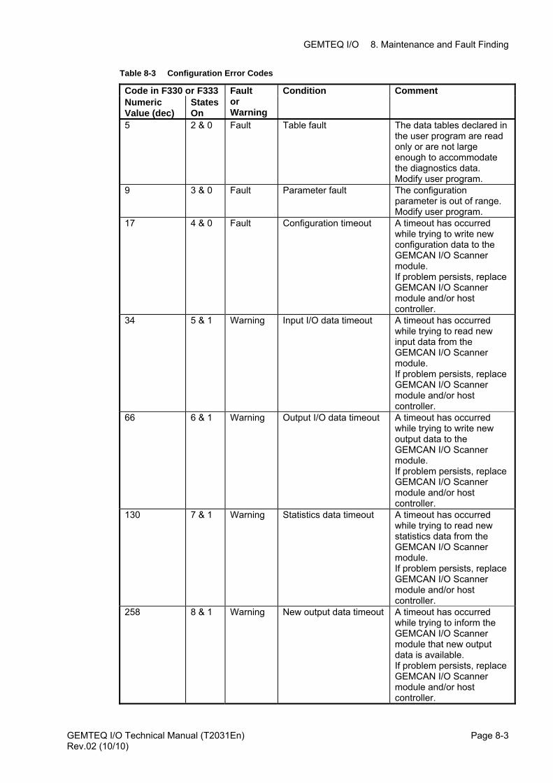
GEMTEQ I/O 8. Maintenance and Fault Finding
Table 8-3 Configuration Error Codes
Code in F330 or F333 Condition Comment Numeric Value (dec)
States On
Fault or Warning
5 2 & 0 Fault Table fault The data tables declared in the user program are read only or are not large enough to accommodate the diagnostics data. Modify user program.
9 3 & 0 Fault Parameter fault The configuration parameter is out of range. Modify user program.
17 4 & 0 Fault Configuration timeout A timeout has occurred while trying to write new configuration data to the GEMCAN I/O Scanner module. If problem persists, replace GEMCAN I/O Scanner module and/or host controller.
34 5 & 1 Warning Input I/O data timeout A timeout has occurred while trying to read new input data from the GEMCAN I/O Scanner module. If problem persists, replace GEMCAN I/O Scanner module and/or host controller.
66 6 & 1 Warning Output I/O data timeout A timeout has occurred while trying to write new output data to the GEMCAN I/O Scanner module. If problem persists, replace GEMCAN I/O Scanner module and/or host controller.
130 7 & 1 Warning Statistics data timeout A timeout has occurred while trying to read new statistics data from the GEMCAN I/O Scanner module. If problem persists, replace GEMCAN I/O Scanner module and/or host controller.
258 8 & 1 Warning New output data timeout A timeout has occurred while trying to inform the GEMCAN I/O Scanner module that new output data is available. If problem persists, replace GEMCAN I/O Scanner module and/or host controller.
GEMTEQ I/O Technical Manual (T2031En) Page 8-3Rev.02 (10/10)
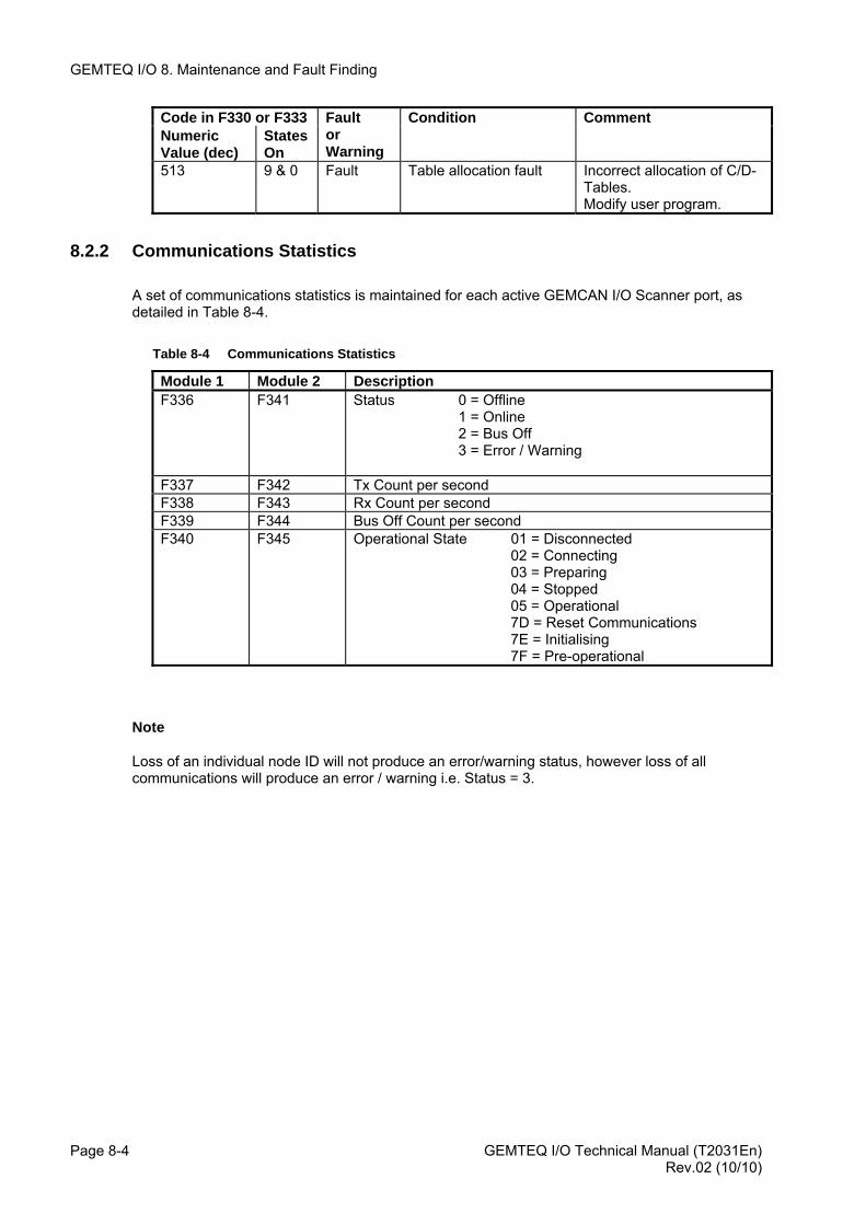
GEMTEQ I/O 8. Maintenance and Fault Finding
GEMTEQ I/O Technical Manual (T2031En) Page 8-4
Code in F330 or F333 Condition Comment Numeric Value (dec)
States On
Fault or Warning
513 9 & 0 Fault Table allocation fault Incorrect allocation of C/D-Tables. Modify user program.
8.2.2 Communications Statistics
A set of communications statistics is maintained for each active GEMCAN I/O Scanner port, as detailed in Table 8-4.
Table 8-4 Communications Statistics
Module 1 Module 2 Description F336 F341 Status 0 = Offline
1 = Online 2 = Bus Off 3 = Error / Warning
F337 F342 Tx Count per second F338 F343 Rx Count per second F339 F344 Bus Off Count per second F340 F345 Operational State 01 = Disconnected
02 = Connecting 03 = Preparing 04 = Stopped 05 = Operational 7D = Reset Communications 7E = Initialising 7F = Pre-operational
Note
Loss of an individual node ID will not produce an error/warning status, however loss of all communications will produce an error / warning i.e. Status = 3.
Rev.02 (10/10)
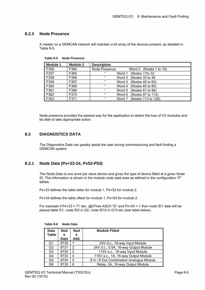
GEMTEQ I/O 8. Maintenance and Fault Finding
8.2.3 Node Presence
A master on a GEMCAN network will maintain a bit array of the devices present, as detailed in Table 8-5.
Table 8-5 Node Presence
Module 1 Module 2 Description F356 F364 Node Presence Word 0 (Nodes 1 to 16) F357 F365 “ Word 1 (Nodes 17to 32 F358 F366 “ Word 2 (Nodes 33 to 48 F359 F367 “ Word 3 (Nodes 49 to 64) F360 F368 “ Word 4 (Nodes 65 to 80) F361 F369 “ Word 5 (Nodes 81 to 96) F362 F370 “ Word 6 (Nodes 97 to 112) F363 F371 “ Word 7 (Nodes 113 to 128)
Node presence provides the easiest way for the application to detect the loss of I/O modules and be able to take appropriate action.
8.3 DIAGNOSTICS DATA
The Diagnostics Data can greatly assist the user during commissioning and fault finding a GEMCAN system.
8.3.1 Node Data (Px+23-24, Px52-P53)
The Node Data is one word per slave device and gives the type of device fitted at a given Node ID. The information is shown in the module node data area as defined in the configuration “P” tables.
Px+23 defines the table letter for module 1, Px+52 for module 2.
Px+24 defines the table offset for module 1, Px+53 for module 2.
For example if Px+23 = 71 dec @47hex ASCII “G” and Px+24 = 1 then node ID1 data will be placed table G1, node ID2 in G2, node ID10 in G10 etc (see table below).
Table 8-6 Node Data
Data Table
Node
Data
Node
Add.
Module Fitted
G1 9730 1 24V d.c., 16-way Input Module G2 9731 2 24V d.c., 0.5A, 16-way Output Module G3 9732 3 110V a.c., 16-way Input Module G4 9733 4 110V a.c., 1A, 16-way Output Module G5 9734 5 8 In / 8 Out Combination Analogue Module G6 9735 6 Relay, 3A, 16-way Output Module
GEMTEQ I/O Technical Manual (T2031En) Page 8-5Rev.02 (10/10)
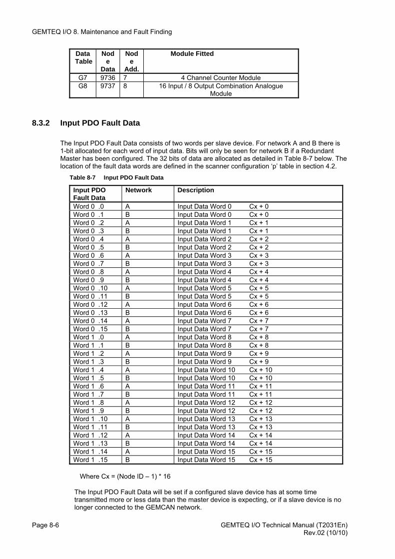
GEMTEQ I/O 8. Maintenance and Fault Finding
GEMTEQ I/O Technical Manual (T2031En) Page 8-6
Data Table
Node
Data
Node
Add.
Module Fitted
G7 9736 7 4 Channel Counter Module G8 9737 8 16 Input / 8 Output Combination Analogue
Module
8.3.2 Input PDO Fault Data
The Input PDO Fault Data consists of two words per slave device. For network A and B there is 1-bit allocated for each word of input data. Bits will only be seen for network B if a Redundant Master has been configured. The 32 bits of data are allocated as detailed in Table 8-7 below. The location of the fault data words are defined in the scanner configuration ‘p’ table in section 4.2.
Table 8-7 Input PDO Fault Data
Input PDO Fault Data
Network Description
Word 0 .0 A Input Data Word 0 Cx + 0 Word 0 .1 B Input Data Word 0 Cx + 0 Word 0 .2 A Input Data Word 1 Cx + 1 Word 0 .3 B Input Data Word 1 Cx + 1 Word 0 .4 A Input Data Word 2 Cx + 2 Word 0 .5 B Input Data Word 2 Cx + 2 Word 0 .6 A Input Data Word 3 Cx + 3 Word 0 .7 B Input Data Word 3 Cx + 3 Word 0 .8 A Input Data Word 4 Cx + 4 Word 0 .9 B Input Data Word 4 Cx + 4 Word 0 .10 A Input Data Word 5 Cx + 5 Word 0 .11 B Input Data Word 5 Cx + 5 Word 0 .12 A Input Data Word 6 Cx + 6 Word 0 .13 B Input Data Word 6 Cx + 6 Word 0 .14 A Input Data Word 7 Cx + 7 Word 0 .15 B Input Data Word 7 Cx + 7 Word 1 .0 A Input Data Word 8 Cx + 8 Word 1 .1 B Input Data Word 8 Cx + 8 Word 1 .2 A Input Data Word 9 Cx + 9 Word 1 .3 B Input Data Word 9 Cx + 9 Word 1 .4 A Input Data Word 10 Cx + 10 Word 1 .5 B Input Data Word 10 Cx + 10 Word 1 .6 A Input Data Word 11 Cx + 11 Word 1 .7 B Input Data Word 11 Cx + 11 Word 1 .8 A Input Data Word 12 Cx + 12 Word 1 .9 B Input Data Word 12 Cx + 12 Word 1 .10 A Input Data Word 13 Cx + 13 Word 1 .11 B Input Data Word 13 Cx + 13 Word 1 .12 A Input Data Word 14 Cx + 14 Word 1 .13 B Input Data Word 14 Cx + 14 Word 1 .14 A Input Data Word 15 Cx + 15 Word 1 .15 B Input Data Word 15 Cx + 15
Where Cx = (Node ID – 1) * 16
The Input PDO Fault Data will be set if a configured slave device has at some time transmitted more or less data than the master device is expecting, or if a slave device is no longer connected to the GEMCAN network.
Rev.02 (10/10)
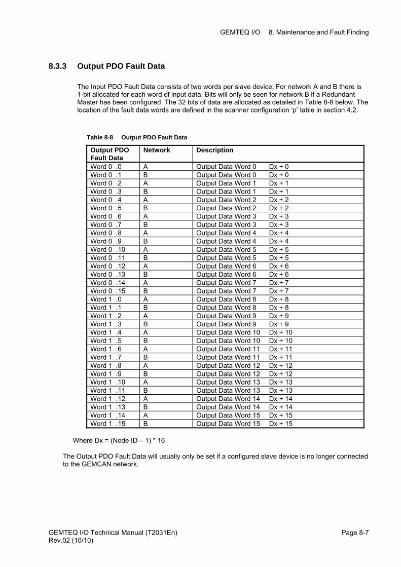
GEMTEQ I/O 8. Maintenance and Fault Finding
8.3.3 Output PDO Fault Data
The Input PDO Fault Data consists of two words per slave device. For network A and B there is 1-bit allocated for each word of input data. Bits will only be seen for network B if a Redundant Master has been configured. The 32 bits of data are allocated as detailed in Table 8-8 below. The location of the fault data words are defined in the scanner configuration ‘p’ table in section 4.2.
Table 8-8 Output PDO Fault Data
Output PDO Fault Data
Network Description
Word 0 .0 A Output Data Word 0 Dx + 0 Word 0 .1 B Output Data Word 0 Dx + 0 Word 0 .2 A Output Data Word 1 Dx + 1 Word 0 .3 B Output Data Word 1 Dx + 1 Word 0 .4 A Output Data Word 2 Dx + 2 Word 0 .5 B Output Data Word 2 Dx + 2 Word 0 .6 A Output Data Word 3 Dx + 3 Word 0 .7 B Output Data Word 3 Dx + 3 Word 0 .8 A Output Data Word 4 Dx + 4 Word 0 .9 B Output Data Word 4 Dx + 4 Word 0 .10 A Output Data Word 5 Dx + 5 Word 0 .11 B Output Data Word 5 Dx + 5 Word 0 .12 A Output Data Word 6 Dx + 6 Word 0 .13 B Output Data Word 6 Dx + 6 Word 0 .14 A Output Data Word 7 Dx + 7 Word 0 .15 B Output Data Word 7 Dx + 7 Word 1 .0 A Output Data Word 8 Dx + 8 Word 1 .1 B Output Data Word 8 Dx + 8 Word 1 .2 A Output Data Word 9 Dx + 9 Word 1 .3 B Output Data Word 9 Dx + 9 Word 1 .4 A Output Data Word 10 Dx + 10 Word 1 .5 B Output Data Word 10 Dx + 10 Word 1 .6 A Output Data Word 11 Dx + 11 Word 1 .7 B Output Data Word 11 Dx + 11 Word 1 .8 A Output Data Word 12 Dx + 12 Word 1 .9 B Output Data Word 12 Dx + 12 Word 1 .10 A Output Data Word 13 Dx + 13 Word 1 .11 B Output Data Word 13 Dx + 13 Word 1 .12 A Output Data Word 14 Dx + 14 Word 1 .13 B Output Data Word 14 Dx + 14 Word 1 .14 A Output Data Word 15 Dx + 15 Word 1 .15 B Output Data Word 15 Dx + 15
Where Dx = (Node ID – 1) * 16
The Output PDO Fault Data will usually only be set if a configured slave device is no longer connected to the GEMCAN network.
GEMTEQ I/O Technical Manual (T2031En) Page 8-7Rev.02 (10/10)
GEMTEQ I/O 8. Maintenance and Fault Finding
8.4 REPAIRS TO GEM80 EQUIPMENT
GEM 80 equipment is repaired by replacement of faulty modules and units. GEM 80 modules are not considered to be user repairable and any attempt to carry out repairs to modules will invalidate all warranties and guarantees. Converteam cannot accept responsibility for GEM 80 equipment that has been repaired, other than by Converteam Customer Support Department.
8.5 FAULT FINDING BACK-UP AND MODULE REPAIR SERVICE
To assist the user in the diagnosis and rectification of faults to GEM 80 equipment, the following services are available from Converteam:
(a) Product Service Centre Customer Support - available to any GEM 80 user.
(b) A 'service contract' scheme for complete GEM 80 systems.
(c) A Normal and Priority Repair Service - available for repair of GEM 80 equipment.
For Customer Support on any aspect of GEM 80 applications, please call:
Product Service Centre Customer Support
Telephone: +44 (0) 1782 781000
Fax: +44 (0) 1782 781133
e-mail: [email protected]
Any faulty modules should be returned for repair to:
Product Service Centre – Spares and Repairs Dept,
Converteam Ltd.,
West Avenue,
Kidsgrove,
Stoke-on-Trent,
Staffs.,
ST7 1TW
England.
Tel: +44 (0) 1782 781128
Fax: +44 (0) 1782 781133
e-mail: [email protected]
Faulty modules or units for repair, should be returned in packing which includes antistatic bags next to the electronic circuitry. Where possible the original packing should be used.
GEMTEQ I/O Technical Manual (T2031En) Page 8-8 Rev.02 (10/10)
GEMTEQ I/O 8. Maintenance and Fault Finding
8.6 DISPOSAL
The GEMCAN I/O Scanner and GEMTEQ I/O modules should be disposed of in accordance with the laws of the country of use.
Modern high technology materials have been used in the manufacture of the controller to ensure optimum performance. Care has been taken with the selection of these materials to minimise risks to health and safety. However, some materials require special consideration during disposal e.g. the battery which is a Lithium Thionyl Chloride type.
It is recommended that the controller be returned to Converteam for safe disposal. Prior arrangements should be made for return to the address at Section 8.5. Alternatively the controller may be returned to the nearest Converteam service centre.
GEMTEQ I/O Technical Manual (T2031En) Page 8-9Rev.02 (10/10)

GEMTEQ I/O 8. Maintenance and Fault Finding
This page left intentionally blank
GEMTEQ I/O Technical Manual (T2031En) Page 8-10 Rev.02 (10/10)
GEMTEQ I/O Appendix A. GEM80-500 Data Summary
APPENDIX A GEM80-500 GEMCAN I/O SCANNER : MODULE 1 DATA SUMMARY
GEMTEQ I/O Technical Manual (T2031En) Page A-1Rev.02 (10/10)
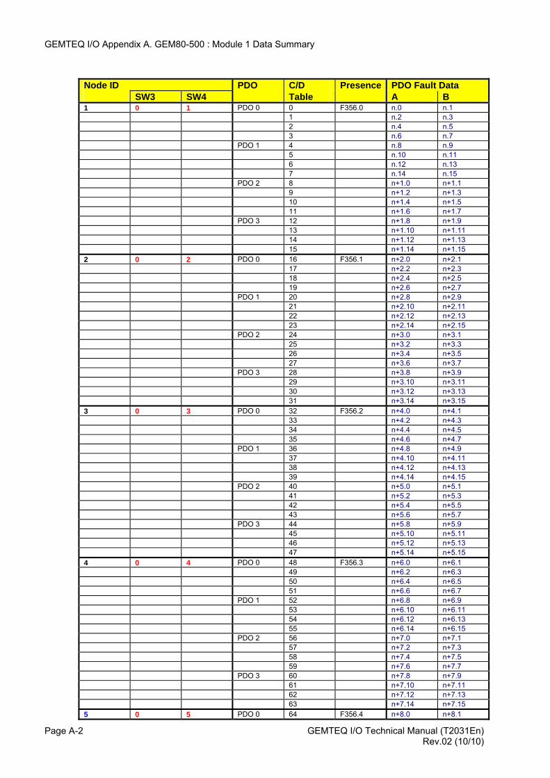
GEMTEQ I/O Appendix A. GEM80-500 : Module 1 Data Summary
Node ID PDO C/D Presence PDO Fault Data SW3 SW4 Table A B 1 0 1 PDO 0 0 F356.0 n.0 n.1 1 n.2 n.3 2 n.4 n.5 3 n.6 n.7 PDO 1 4 n.8 n.9 5 n.10 n.11 6 n.12 n.13 7 n.14 n.15 PDO 2 8 n+1.0 n+1.1 9 n+1.2 n+1.3 10 n+1.4 n+1.5 11 n+1.6 n+1.7 PDO 3 12 n+1.8 n+1.9 13 n+1.10 n+1.11 14 n+1.12 n+1.13 15 n+1.14 n+1.15 2 0 2 PDO 0 16 F356.1 n+2.0 n+2.1 17 n+2.2 n+2.3 18 n+2.4 n+2.5 19 n+2.6 n+2.7 PDO 1 20 n+2.8 n+2.9 21 n+2.10 n+2.11 22 n+2.12 n+2.13 23 n+2.14 n+2.15 PDO 2 24 n+3.0 n+3.1 25 n+3.2 n+3.3 26 n+3.4 n+3.5 27 n+3.6 n+3.7 PDO 3 28 n+3.8 n+3.9 29 n+3.10 n+3.11 30 n+3.12 n+3.13 31 n+3.14 n+3.15 3 0 3 PDO 0 32 F356.2 n+4.0 n+4.1 33 n+4.2 n+4.3 34 n+4.4 n+4.5 35 n+4.6 n+4.7 PDO 1 36 n+4.8 n+4.9 37 n+4.10 n+4.11 38 n+4.12 n+4.13 39 n+4.14 n+4.15 PDO 2 40 n+5.0 n+5.1 41 n+5.2 n+5.3 42 n+5.4 n+5.5 43 n+5.6 n+5.7 PDO 3 44 n+5.8 n+5.9 45 n+5.10 n+5.11 46 n+5.12 n+5.13 47 n+5.14 n+5.15 4 0 4 PDO 0 48 F356.3 n+6.0 n+6.1 49 n+6.2 n+6.3 50 n+6.4 n+6.5 51 n+6.6 n+6.7 PDO 1 52 n+6.8 n+6.9 53 n+6.10 n+6.11 54 n+6.12 n+6.13 55 n+6.14 n+6.15 PDO 2 56 n+7.0 n+7.1 57 n+7.2 n+7.3 58 n+7.4 n+7.5 59 n+7.6 n+7.7 PDO 3 60 n+7.8 n+7.9 61 n+7.10 n+7.11 62 n+7.12 n+7.13 63 n+7.14 n+7.15 5 0 5 PDO 0 64 F356.4 n+8.0 n+8.1
GEMTEQ I/O Technical Manual (T2031En) Page A-2 Rev.02 (10/10)
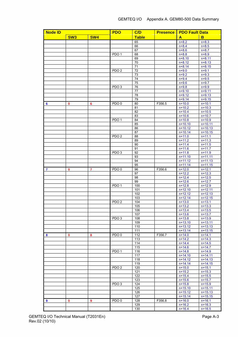
GEMTEQ I/O Appendix A. GEM80-500 Data Summary
GEMTEQ I/O Technical Manual (T2031En) Page A-3
Node ID PDO C/D Presence PDO Fault Data SW3 SW4 Table A B 65 n+8.2 n+8.3 66 n+8.4 n+8.5 67 n+8.6 n+8.7 PDO 1 68 n+8.8 n+8.9 69 n+8.10 n+8.11 70 n+8.12 n+8.13 71 n+8.14 n+8.15 PDO 2 72 n+9.0 n+9.1 73 n+9.2 n+9.3 74 n+9.4 n+9.5 75 n+9.6 n+9.7 PDO 3 76 n+9.8 n+9.9 77 n+9.10 n+9.11 78 n+9.12 n+9.13 79 n+9.14 n+9.15 6 0 6 PDO 0 80 F356.5 n+10.0 n+10.1 81 n+10.2 n+10.3 82 n+10.4 n+10.5 83 n+10.6 n+10.7 PDO 1 84 n+10.8 n+10.9 85 n+10.10 n+10.11 86 n+10.12 n+10.13 87 n+10.14 n+10.15 PDO 2 88 n+11.0 n+11.1 89 n+11.2 n+11.3 90 n+11.4 n+11.5 91 n+11.6 n+11.7 PDO 3 92 n+11.8 n+11.9 93 n+11.10 n+11.11 94 n+11.12 n+11.13 95 n+11.14 n+11.15 7 0 7 PDO 0 96 F356.6 n+12.0 n+12.1 97 n+12.2 n+12.3 98 n+12.4 n+12.5 99 n+12.6 n+12.7 PDO 1 100 n+12.8 n+12.9 101 n+12.10 n+12.11 102 n+12.12 n+12.13 103 n+12.14 n+12.15 PDO 2 104 n+13.0 n+13.1 105 n+13.2 n+13.3 106 n+13.4 n+13.5 107 n+13.6 n+13.7 PDO 3 108 n+13.8 n+13.9 109 n+13.10 n+13.11 110 n+13.12 n+13.13 111 n+13.14 n+13.15 8 0 8 PDO 0 112 F356.7 n+14.0 n+14.1 113 n+14.2 n+14.3 114 n+14.4 n+14.5 115 n+14.6 n+14.7 PDO 1 116 n+14.8 n+14.9 117 n+14.10 n+14.11 118 n+14.12 n+14.13 119 n+14.14 n+14.15 PDO 2 120 n+15.0 n+15.1 121 n+15.2 n+15.3 122 n+15.4 n+15.5 123 n+15.6 n+15.7 PDO 3 124 n+15.8 n+15.9 125 n+15.10 n+15.11 126 n+15.12 n+15.13 127 n+15.14 n+15.15 9 0 9 PDO 0 128 F356.8 n+16.0 n+16.1 129 n+16.2 n+16.3 130 n+16.4 n+16.5
Rev.02 (10/10)
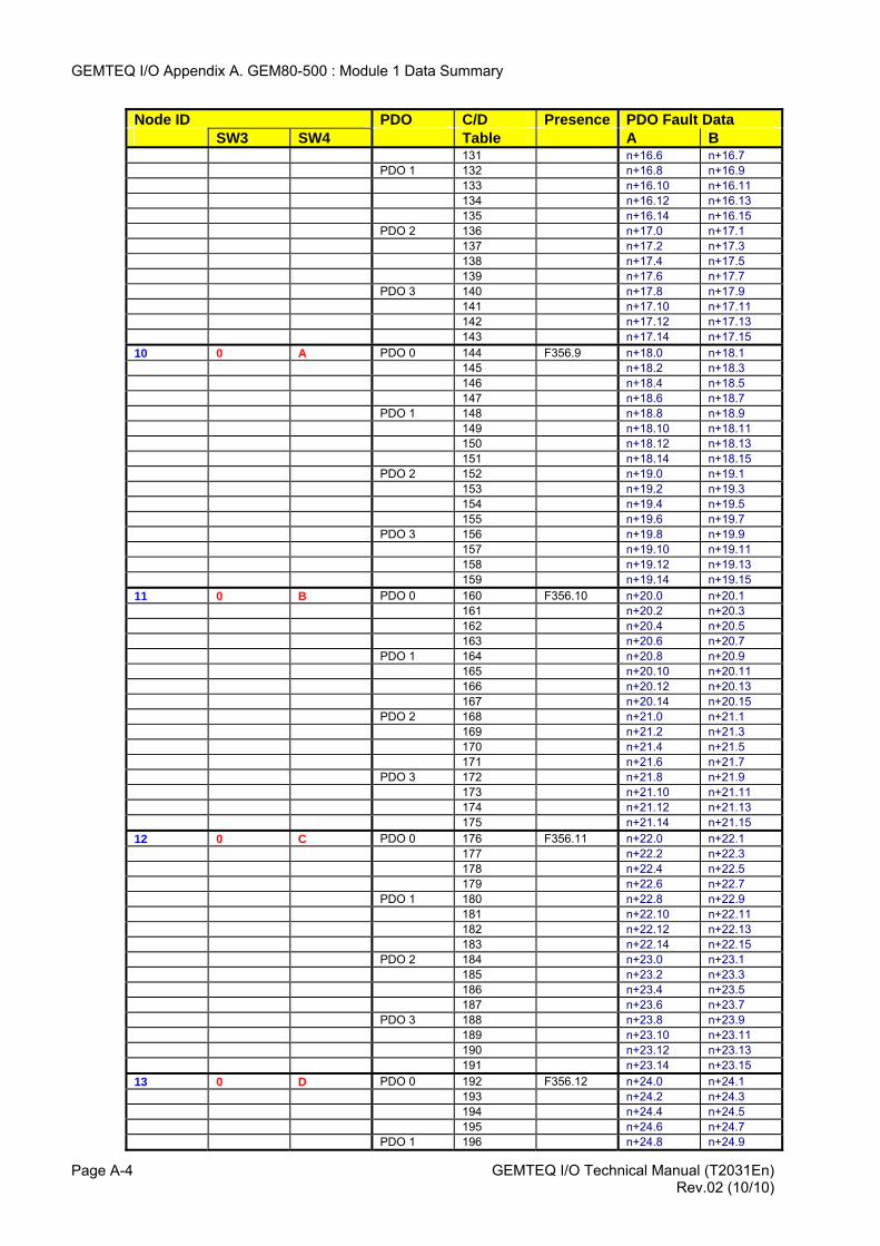
GEMTEQ I/O Appendix A. GEM80-500 : Module 1 Data Summary
GEMTEQ I/O Technical Manual (T2031En) Page A-4
Node ID PDO C/D Presence PDO Fault Data SW3 SW4 Table A B 131 n+16.6 n+16.7 PDO 1 132 n+16.8 n+16.9 133 n+16.10 n+16.11 134 n+16.12 n+16.13 135 n+16.14 n+16.15 PDO 2 136 n+17.0 n+17.1 137 n+17.2 n+17.3 138 n+17.4 n+17.5 139 n+17.6 n+17.7 PDO 3 140 n+17.8 n+17.9 141 n+17.10 n+17.11 142 n+17.12 n+17.13 143 n+17.14 n+17.15 10 0 A PDO 0 144 F356.9 n+18.0 n+18.1 145 n+18.2 n+18.3 146 n+18.4 n+18.5 147 n+18.6 n+18.7 PDO 1 148 n+18.8 n+18.9 149 n+18.10 n+18.11 150 n+18.12 n+18.13 151 n+18.14 n+18.15 PDO 2 152 n+19.0 n+19.1 153 n+19.2 n+19.3 154 n+19.4 n+19.5 155 n+19.6 n+19.7 PDO 3 156 n+19.8 n+19.9 157 n+19.10 n+19.11 158 n+19.12 n+19.13 159 n+19.14 n+19.15 11 0 B PDO 0 160 F356.10 n+20.0 n+20.1 161 n+20.2 n+20.3 162 n+20.4 n+20.5 163 n+20.6 n+20.7 PDO 1 164 n+20.8 n+20.9 165 n+20.10 n+20.11 166 n+20.12 n+20.13 167 n+20.14 n+20.15 PDO 2 168 n+21.0 n+21.1 169 n+21.2 n+21.3 170 n+21.4 n+21.5 171 n+21.6 n+21.7 PDO 3 172 n+21.8 n+21.9 173 n+21.10 n+21.11 174 n+21.12 n+21.13 175 n+21.14 n+21.15 12 0 C PDO 0 176 F356.11 n+22.0 n+22.1 177 n+22.2 n+22.3 178 n+22.4 n+22.5 179 n+22.6 n+22.7 PDO 1 180 n+22.8 n+22.9 181 n+22.10 n+22.11 182 n+22.12 n+22.13 183 n+22.14 n+22.15 PDO 2 184 n+23.0 n+23.1 185 n+23.2 n+23.3 186 n+23.4 n+23.5 187 n+23.6 n+23.7 PDO 3 188 n+23.8 n+23.9 189 n+23.10 n+23.11 190 n+23.12 n+23.13 191 n+23.14 n+23.15 13 0 D PDO 0 192 F356.12 n+24.0 n+24.1 193 n+24.2 n+24.3 194 n+24.4 n+24.5 195 n+24.6 n+24.7 PDO 1 196 n+24.8 n+24.9
Rev.02 (10/10)
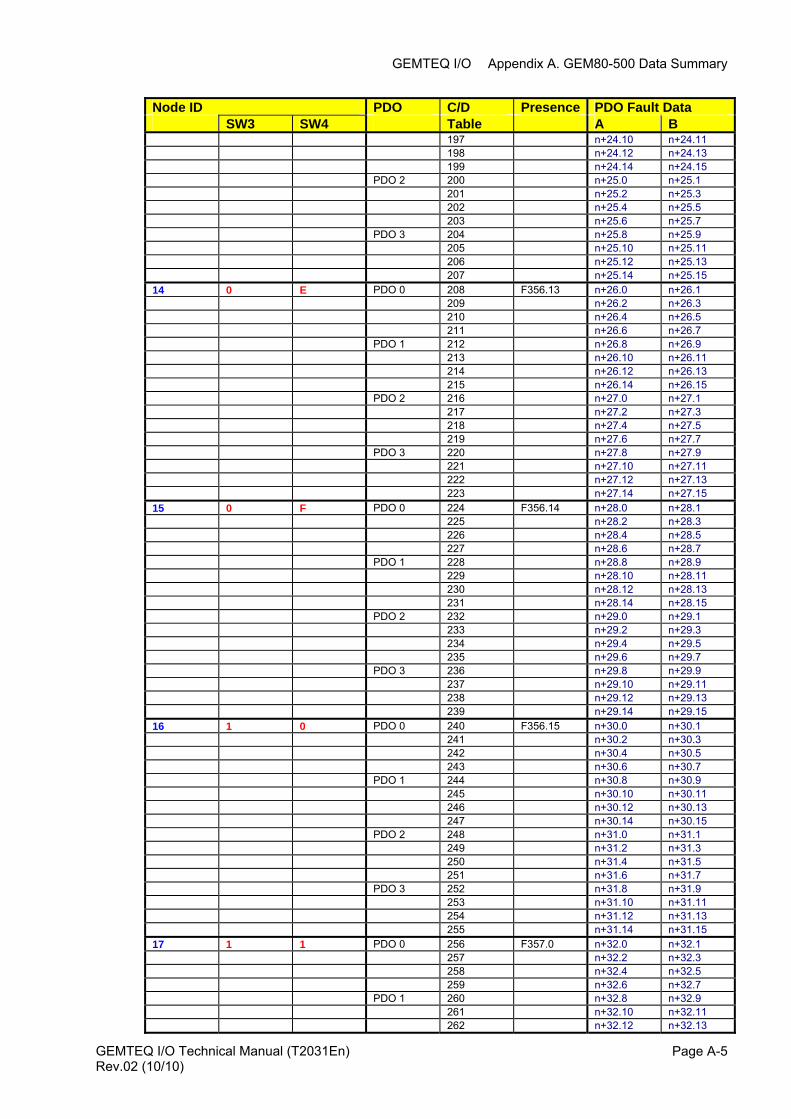
GEMTEQ I/O Appendix A. GEM80-500 Data Summary
GEMTEQ I/O Technical Manual (T2031En) Page A-5Rev.02 (10/10)
Node ID PDO C/D Presence PDO Fault Data SW3 SW4 Table A B 197 n+24.10 n+24.11 198 n+24.12 n+24.13 199 n+24.14 n+24.15 PDO 2 200 n+25.0 n+25.1 201 n+25.2 n+25.3 202 n+25.4 n+25.5 203 n+25.6 n+25.7 PDO 3 204 n+25.8 n+25.9 205 n+25.10 n+25.11 206 n+25.12 n+25.13 207 n+25.14 n+25.15 14 0 E PDO 0 208 F356.13 n+26.0 n+26.1 209 n+26.2 n+26.3 210 n+26.4 n+26.5 211 n+26.6 n+26.7 PDO 1 212 n+26.8 n+26.9 213 n+26.10 n+26.11 214 n+26.12 n+26.13 215 n+26.14 n+26.15 PDO 2 216 n+27.0 n+27.1 217 n+27.2 n+27.3 218 n+27.4 n+27.5 219 n+27.6 n+27.7 PDO 3 220 n+27.8 n+27.9 221 n+27.10 n+27.11 222 n+27.12 n+27.13 223 n+27.14 n+27.15 15 0 F PDO 0 224 F356.14 n+28.0 n+28.1 225 n+28.2 n+28.3 226 n+28.4 n+28.5 227 n+28.6 n+28.7 PDO 1 228 n+28.8 n+28.9 229 n+28.10 n+28.11 230 n+28.12 n+28.13 231 n+28.14 n+28.15 PDO 2 232 n+29.0 n+29.1 233 n+29.2 n+29.3 234 n+29.4 n+29.5 235 n+29.6 n+29.7 PDO 3 236 n+29.8 n+29.9 237 n+29.10 n+29.11 238 n+29.12 n+29.13 239 n+29.14 n+29.15 16 1 0 PDO 0 240 F356.15 n+30.0 n+30.1 241 n+30.2 n+30.3 242 n+30.4 n+30.5 243 n+30.6 n+30.7 PDO 1 244 n+30.8 n+30.9 245 n+30.10 n+30.11 246 n+30.12 n+30.13 247 n+30.14 n+30.15 PDO 2 248 n+31.0 n+31.1 249 n+31.2 n+31.3 250 n+31.4 n+31.5 251 n+31.6 n+31.7 PDO 3 252 n+31.8 n+31.9 253 n+31.10 n+31.11 254 n+31.12 n+31.13 255 n+31.14 n+31.15 17 1 1 PDO 0 256 F357.0 n+32.0 n+32.1 257 n+32.2 n+32.3 258 n+32.4 n+32.5 259 n+32.6 n+32.7 PDO 1 260 n+32.8 n+32.9 261 n+32.10 n+32.11 262 n+32.12 n+32.13
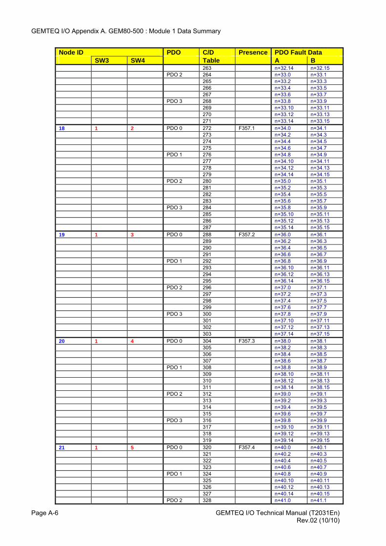
GEMTEQ I/O Appendix A. GEM80-500 : Module 1 Data Summary
Node ID PDO C/D Presence PDO Fault Data SW3 SW4 Table A B 263 n+32.14 n+32.15 PDO 2 264 n+33.0 n+33.1 265 n+33.2 n+33.3 266 n+33.4 n+33.5 267 n+33.6 n+33.7 PDO 3 268 n+33.8 n+33.9 269 n+33.10 n+33.11 270 n+33.12 n+33.13 271 n+33.14 n+33.15 18 1 2 PDO 0 272 F357.1 n+34.0 n+34.1 273 n+34.2 n+34.3 274 n+34.4 n+34.5 275 n+34.6 n+34.7 PDO 1 276 n+34.8 n+34.9 277 n+34.10 n+34.11 278 n+34.12 n+34.13 279 n+34.14 n+34.15 PDO 2 280 n+35.0 n+35.1 281 n+35.2 n+35.3 282 n+35.4 n+35.5 283 n+35.6 n+35.7 PDO 3 284 n+35.8 n+35.9 285 n+35.10 n+35.11 286 n+35.12 n+35.13 287 n+35.14 n+35.15 19 1 3 PDO 0 288 F357.2 n+36.0 n+36.1 289 n+36.2 n+36.3 290 n+36.4 n+36.5 291 n+36.6 n+36.7 PDO 1 292 n+36.8 n+36.9 293 n+36.10 n+36.11 294 n+36.12 n+36.13 295 n+36.14 n+36.15 PDO 2 296 n+37.0 n+37.1 297 n+37.2 n+37.3 298 n+37.4 n+37.5 299 n+37.6 n+37.7 PDO 3 300 n+37.8 n+37.9 301 n+37.10 n+37.11 302 n+37.12 n+37.13 303 n+37.14 n+37.15 20 1 4 PDO 0 304 F357.3 n+38.0 n+38.1 305 n+38.2 n+38.3 306 n+38.4 n+38.5 307 n+38.6 n+38.7 PDO 1 308 n+38.8 n+38.9 309 n+38.10 n+38.11 310 n+38.12 n+38.13 311 n+38.14 n+38.15 PDO 2 312 n+39.0 n+39.1 313 n+39.2 n+39.3 314 n+39.4 n+39.5 315 n+39.6 n+39.7 PDO 3 316 n+39.8 n+39.9 317 n+39.10 n+39.11 318 n+39.12 n+39.13 319 n+39.14 n+39.15 21 1 5 PDO 0 320 F357.4 n+40.0 n+40.1 321 n+40.2 n+40.3 322 n+40.4 n+40.5 323 n+40.6 n+40.7 PDO 1 324 n+40.8 n+40.9 325 n+40.10 n+40.11 326 n+40.12 n+40.13 327 n+40.14 n+40.15 PDO 2 328 n+41.0 n+41.1
GEMTEQ I/O Technical Manual (T2031En) Page A-6 Rev.02 (10/10)
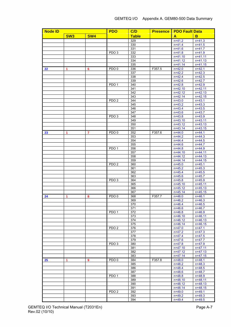
GEMTEQ I/O Appendix A. GEM80-500 Data Summary
Node ID PDO C/D Presence PDO Fault Data SW3 SW4 Table A B 329 n+41.2 n+41.3 330 n+41.4 n+41.5 331 n+41.6 n+41.7 PDO 3 332 n+41.8 n+41.9 333 n+41.10 n+41.11 334 n+41.12 n+41.13 335 n+41.14 n+41.15 22 1 6 PDO 0 336 F357.5 n+42.0 n+42.1 337 n+42.2 n+42.3 338 n+42.4 n+42.5 339 n+42.6 n+42.7 PDO 1 340 n+42.8 n+42.9 341 n+42.10 n+42.11 342 n+42.12 n+42.13 343 n+42.14 n+42.15 PDO 2 344 n+43.0 n+43.1 345 n+43.2 n+43.3 346 n+43.4 n+43.5 347 n+43.6 n+43.7 PDO 3 348 n+43.8 n+43.9 349 n+43.10 n+43.11 350 n+43.12 n+43.13 351 n+43.14 n+43.15 23 1 7 PDO 0 352 F357.6 n+44.0 n+44.1 353 n+44.2 n+44.3 354 n+44.4 n+44.5 355 n+44.6 n+44.7 PDO 1 356 n+44.8 n+44.9 357 n+44.10 n+44.11 358 n+44.12 n+44.13 359 n+44.14 n+44.15 PDO 2 360 n+45.0 n+45.1 361 n+45.2 n+45.3 362 n+45.4 n+45.5 363 n+45.6 n+45.7 PDO 3 364 n+45.8 n+45.9 365 n+45.10 n+45.11 366 n+45.12 n+45.13 367 n+45.14 n+45.15 24 1 8 PDO 0 368 F357.7 n+46.0 n+46.1 369 n+46.2 n+46.3 370 n+46.4 n+46.5 371 n+46.6 n+46.7 PDO 1 372 n+46.8 n+46.9 373 n+46.10 n+46.11 374 n+46.12 n+46.13 375 n+46.14 n+46.15 PDO 2 376 n+47.0 n+47.1 377 n+47.2 n+47.3 378 n+47.4 n+47.5 379 n+47.6 n+47.7 PDO 3 380 n+47.8 n+47.9 381 n+47.10 n+47.11 382 n+47.12 n+47.13 383 n+47.14 n+47.15 25 1 9 PDO 0 384 F357.8 n+48.0 n+48.1 385 n+48.2 n+48.3 386 n+48.4 n+48.5 387 n+48.6 n+48.7 PDO 1 388 n+48.8 n+48.9 389 n+48.10 n+48.11 390 n+48.12 n+48.13 391 n+48.14 n+48.15 PDO 2 392 n+49.0 n+49.1 393 n+49.2 n+49.3 394 n+49.4 n+49.5
GEMTEQ I/O Technical Manual (T2031En) Page A-7Rev.02 (10/10)
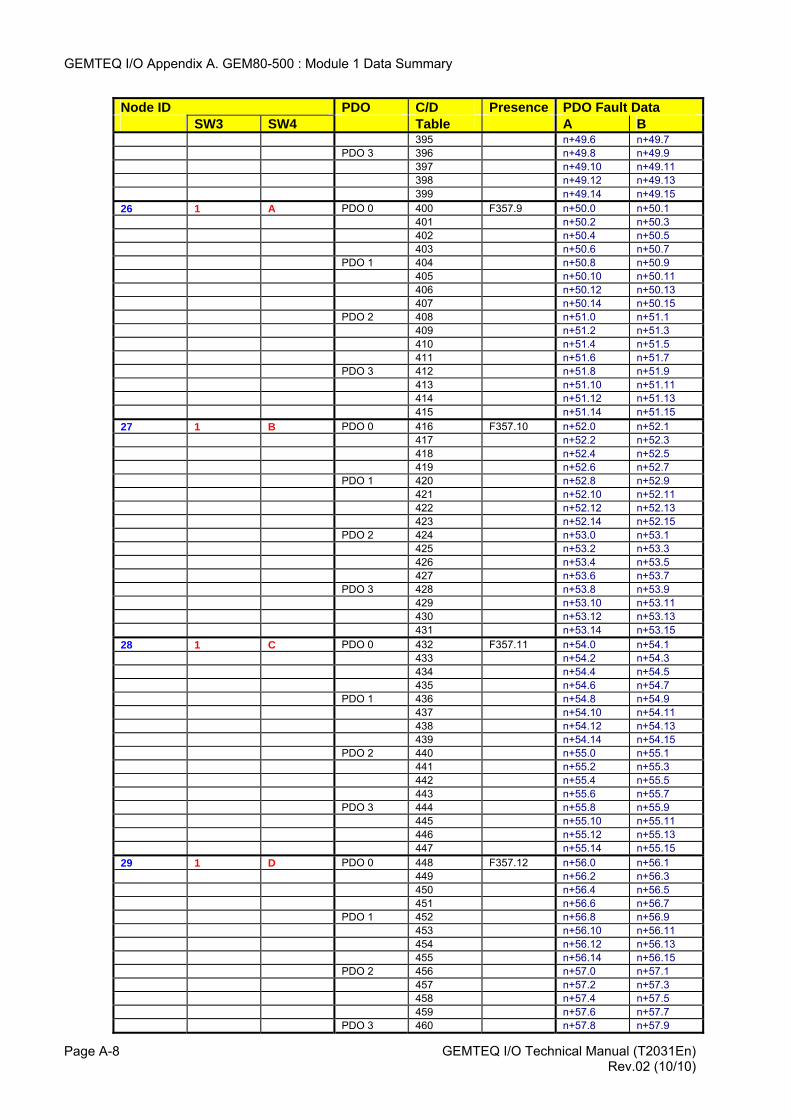
GEMTEQ I/O Appendix A. GEM80-500 : Module 1 Data Summary
Node ID PDO C/D Presence PDO Fault Data SW3 SW4 Table A B 395 n+49.6 n+49.7 PDO 3 396 n+49.8 n+49.9 397 n+49.10 n+49.11 398 n+49.12 n+49.13 399 n+49.14 n+49.15 26 1 A PDO 0 400 F357.9 n+50.0 n+50.1 401 n+50.2 n+50.3 402 n+50.4 n+50.5 403 n+50.6 n+50.7 PDO 1 404 n+50.8 n+50.9 405 n+50.10 n+50.11 406 n+50.12 n+50.13 407 n+50.14 n+50.15 PDO 2 408 n+51.0 n+51.1 409 n+51.2 n+51.3 410 n+51.4 n+51.5 411 n+51.6 n+51.7 PDO 3 412 n+51.8 n+51.9 413 n+51.10 n+51.11 414 n+51.12 n+51.13 415 n+51.14 n+51.15 27 1 B PDO 0 416 F357.10 n+52.0 n+52.1 417 n+52.2 n+52.3 418 n+52.4 n+52.5 419 n+52.6 n+52.7 PDO 1 420 n+52.8 n+52.9 421 n+52.10 n+52.11 422 n+52.12 n+52.13 423 n+52.14 n+52.15 PDO 2 424 n+53.0 n+53.1 425 n+53.2 n+53.3 426 n+53.4 n+53.5 427 n+53.6 n+53.7 PDO 3 428 n+53.8 n+53.9 429 n+53.10 n+53.11 430 n+53.12 n+53.13 431 n+53.14 n+53.15 28 1 C PDO 0 432 F357.11 n+54.0 n+54.1 433 n+54.2 n+54.3 434 n+54.4 n+54.5 435 n+54.6 n+54.7 PDO 1 436 n+54.8 n+54.9 437 n+54.10 n+54.11 438 n+54.12 n+54.13 439 n+54.14 n+54.15 PDO 2 440 n+55.0 n+55.1 441 n+55.2 n+55.3 442 n+55.4 n+55.5 443 n+55.6 n+55.7 PDO 3 444 n+55.8 n+55.9 445 n+55.10 n+55.11 446 n+55.12 n+55.13 447 n+55.14 n+55.15 29 1 D PDO 0 448 F357.12 n+56.0 n+56.1 449 n+56.2 n+56.3 450 n+56.4 n+56.5 451 n+56.6 n+56.7 PDO 1 452 n+56.8 n+56.9 453 n+56.10 n+56.11 454 n+56.12 n+56.13 455 n+56.14 n+56.15 PDO 2 456 n+57.0 n+57.1 457 n+57.2 n+57.3 458 n+57.4 n+57.5 459 n+57.6 n+57.7 PDO 3 460 n+57.8 n+57.9
GEMTEQ I/O Technical Manual (T2031En) Page A-8 Rev.02 (10/10)
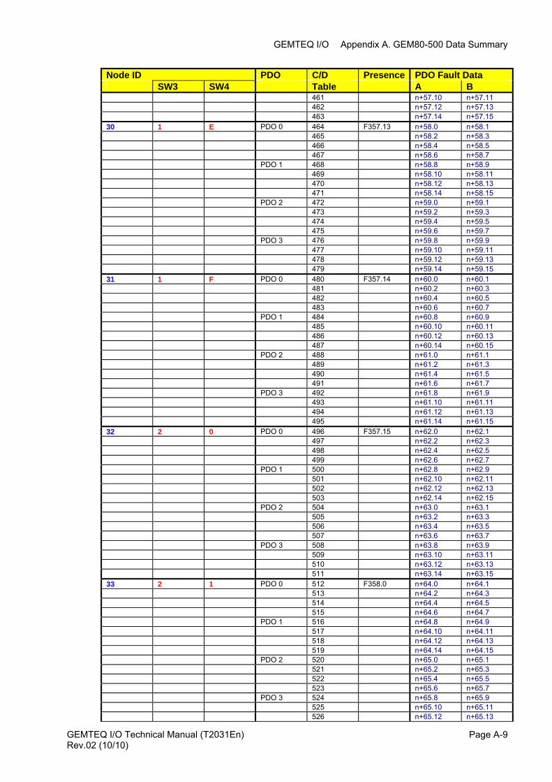
GEMTEQ I/O Appendix A. GEM80-500 Data Summary
Node ID PDO C/D Presence PDO Fault Data SW3 SW4 Table A B 461 n+57.10 n+57.11 462 n+57.12 n+57.13 463 n+57.14 n+57.15 30 1 E PDO 0 464 F357.13 n+58.0 n+58.1 465 n+58.2 n+58.3 466 n+58.4 n+58.5 467 n+58.6 n+58.7 PDO 1 468 n+58.8 n+58.9 469 n+58.10 n+58.11 470 n+58.12 n+58.13 471 n+58.14 n+58.15 PDO 2 472 n+59.0 n+59.1 473 n+59.2 n+59.3 474 n+59.4 n+59.5 475 n+59.6 n+59.7 PDO 3 476 n+59.8 n+59.9 477 n+59.10 n+59.11 478 n+59.12 n+59.13 479 n+59.14 n+59.15 31 1 F PDO 0 480 F357.14 n+60.0 n+60.1 481 n+60.2 n+60.3 482 n+60.4 n+60.5 483 n+60.6 n+60.7 PDO 1 484 n+60.8 n+60.9 485 n+60.10 n+60.11 486 n+60.12 n+60.13 487 n+60.14 n+60.15 PDO 2 488 n+61.0 n+61.1 489 n+61.2 n+61.3 490 n+61.4 n+61.5 491 n+61.6 n+61.7 PDO 3 492 n+61.8 n+61.9 493 n+61.10 n+61.11 494 n+61.12 n+61.13 495 n+61.14 n+61.15 32 2 0 PDO 0 496 F357.15 n+62.0 n+62.1 497 n+62.2 n+62.3 498 n+62.4 n+62.5 499 n+62.6 n+62.7 PDO 1 500 n+62.8 n+62.9 501 n+62.10 n+62.11 502 n+62.12 n+62.13 503 n+62.14 n+62.15 PDO 2 504 n+63.0 n+63.1 505 n+63.2 n+63.3 506 n+63.4 n+63.5 507 n+63.6 n+63.7 PDO 3 508 n+63.8 n+63.9 509 n+63.10 n+63.11 510 n+63.12 n+63.13 511 n+63.14 n+63.15 33 2 1 PDO 0 512 F358.0 n+64.0 n+64.1 513 n+64.2 n+64.3 514 n+64.4 n+64.5 515 n+64.6 n+64.7 PDO 1 516 n+64.8 n+64.9 517 n+64.10 n+64.11 518 n+64.12 n+64.13 519 n+64.14 n+64.15 PDO 2 520 n+65.0 n+65.1 521 n+65.2 n+65.3 522 n+65.4 n+65.5 523 n+65.6 n+65.7 PDO 3 524 n+65.8 n+65.9 525 n+65.10 n+65.11 526 n+65.12 n+65.13
GEMTEQ I/O Technical Manual (T2031En) Page A-9Rev.02 (10/10)
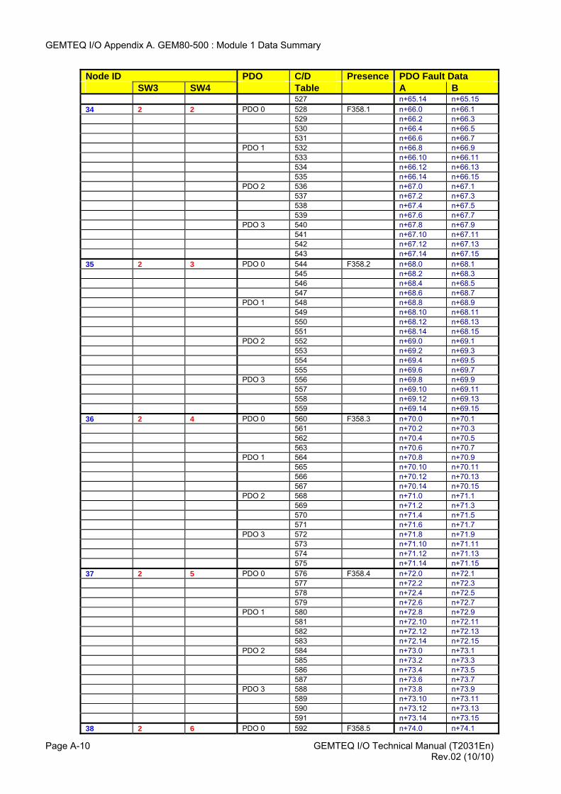
GEMTEQ I/O Appendix A. GEM80-500 : Module 1 Data Summary
Node ID PDO C/D Presence PDO Fault Data SW3 SW4 Table A B 527 n+65.14 n+65.15 34 2 2 PDO 0 528 F358.1 n+66.0 n+66.1 529 n+66.2 n+66.3 530 n+66.4 n+66.5 531 n+66.6 n+66.7 PDO 1 532 n+66.8 n+66.9 533 n+66.10 n+66.11 534 n+66.12 n+66.13 535 n+66.14 n+66.15 PDO 2 536 n+67.0 n+67.1 537 n+67.2 n+67.3 538 n+67.4 n+67.5 539 n+67.6 n+67.7 PDO 3 540 n+67.8 n+67.9 541 n+67.10 n+67.11 542 n+67.12 n+67.13 543 n+67.14 n+67.15 35 2 3 PDO 0 544 F358.2 n+68.0 n+68.1 545 n+68.2 n+68.3 546 n+68.4 n+68.5 547 n+68.6 n+68.7 PDO 1 548 n+68.8 n+68.9 549 n+68.10 n+68.11 550 n+68.12 n+68.13 551 n+68.14 n+68.15 PDO 2 552 n+69.0 n+69.1 553 n+69.2 n+69.3 554 n+69.4 n+69.5 555 n+69.6 n+69.7 PDO 3 556 n+69.8 n+69.9 557 n+69.10 n+69.11 558 n+69.12 n+69.13 559 n+69.14 n+69.15 36 2 4 PDO 0 560 F358.3 n+70.0 n+70.1 561 n+70.2 n+70.3 562 n+70.4 n+70.5 563 n+70.6 n+70.7 PDO 1 564 n+70.8 n+70.9 565 n+70.10 n+70.11 566 n+70.12 n+70.13 567 n+70.14 n+70.15 PDO 2 568 n+71.0 n+71.1 569 n+71.2 n+71.3 570 n+71.4 n+71.5 571 n+71.6 n+71.7 PDO 3 572 n+71.8 n+71.9 573 n+71.10 n+71.11 574 n+71.12 n+71.13 575 n+71.14 n+71.15 37 2 5 PDO 0 576 F358.4 n+72.0 n+72.1 577 n+72.2 n+72.3 578 n+72.4 n+72.5 579 n+72.6 n+72.7 PDO 1 580 n+72.8 n+72.9 581 n+72.10 n+72.11 582 n+72.12 n+72.13 583 n+72.14 n+72.15 PDO 2 584 n+73.0 n+73.1 585 n+73.2 n+73.3 586 n+73.4 n+73.5 587 n+73.6 n+73.7 PDO 3 588 n+73.8 n+73.9 589 n+73.10 n+73.11 590 n+73.12 n+73.13 591 n+73.14 n+73.15 38 2 6 PDO 0 592 F358.5 n+74.0 n+74.1
GEMTEQ I/O Technical Manual (T2031En) Page A-10 Rev.02 (10/10)
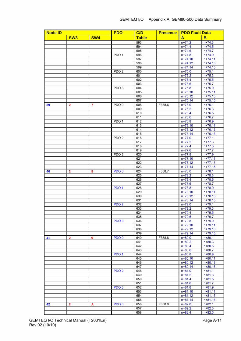
GEMTEQ I/O Appendix A. GEM80-500 Data Summary
Node ID PDO C/D Presence PDO Fault Data SW3 SW4 Table A B 593 n+74.2 n+74.3 594 n+74.4 n+74.5 595 n+74.6 n+74.7 PDO 1 596 n+74.8 n+74.9 597 n+74.10 n+74.11 598 n+74.12 n+74.13 599 n+74.14 n+74.15 PDO 2 600 n+75.0 n+75.1 601 n+75.2 n+75.3 602 n+75.4 n+75.5 603 n+75.6 n+75.7 PDO 3 604 n+75.8 n+75.9 605 n+75.10 n+75.11 606 n+75.12 n+75.13 607 n+75.14 n+75.15 39 2 7 PDO 0 608 F358.6 n+76.0 n+76.1 609 n+76.2 n+76.3 610 n+76.4 n+76.5 611 n+76.6 n+76.7 PDO 1 612 n+76.8 n+76.9 613 n+76.10 n+76.11 614 n+76.12 n+76.13 615 n+76.14 n+76.15 PDO 2 616 n+77.0 n+77.1 617 n+77.2 n+77.3 618 n+77.4 n+77.5 619 n+77.6 n+77.7 PDO 3 620 n+77.8 n+77.9 621 n+77.10 n+77.11 622 n+77.12 n+77.13 623 n+77.14 n+77.15 40 2 8 PDO 0 624 F358.7 n+78.0 n+78.1 625 n+78.2 n+78.3 626 n+78.4 n+78.5 627 n+78.6 n+78.7 PDO 1 628 n+78.8 n+78.9 629 n+78.10 n+78.11 630 n+78.12 n+78.13 631 n+78.14 n+78.15 PDO 2 632 n+79.0 n+79.1 633 n+79.2 n+79.3 634 n+79.4 n+79.5 635 n+79.6 n+79.7 PDO 3 636 n+79.8 n+79.9 637 n+79.10 n+79.11 638 n+79.12 n+79.13 639 n+79.14 n+79.15 41 2 9 PDO 0 640 F358.8 n+80.0 n+80.1 641 n+80.2 n+80.3 642 n+80.4 n+80.5 643 n+80.6 n+80.7 PDO 1 644 n+80.8 n+80.9 645 n+80.10 n+80.11 646 n+80.12 n+80.13 647 n+80.14 n+80.15 PDO 2 648 n+81.0 n+81.1 649 n+81.2 n+81.3 650 n+81.4 n+81.5 651 n+81.6 n+81.7 PDO 3 652 n+81.8 n+81.9 653 n+81.10 n+81.11 654 n+81.12 n+81.13 655 n+81.14 n+81.15 42 2 A PDO 0 656 F358.9 n+82.0 n+82.1 657 n+82.2 n+82.3 658 n+82.4 n+82.5
GEMTEQ I/O Technical Manual (T2031En) Page A-11Rev.02 (10/10)
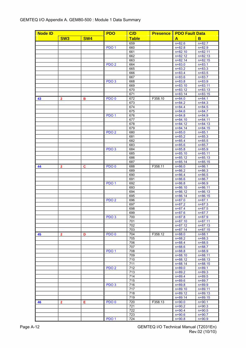
GEMTEQ I/O Appendix A. GEM80-500 : Module 1 Data Summary
Node ID PDO C/D Presence PDO Fault Data SW3 SW4 Table A B 659 n+82.6 n+82.7 PDO 1 660 n+82.8 n+82.9 661 n+82.10 n+82.11 662 n+82.12 n+82.13 663 n+82.14 n+82.15 PDO 2 664 n+83.0 n+83.1 665 n+83.2 n+83.3 666 n+83.4 n+83.5 667 n+83.6 n+83.7 PDO 3 668 n+83.8 n+83.9 669 n+83.10 n+83.11 670 n+83.12 n+83.13 671 n+83.14 n+83.15 43 2 B PDO 0 672 F358.10 n+84.0 n+84.1 673 n+84.2 n+84.3 674 n+84.4 n+84.5 675 n+84.6 n+84.7 PDO 1 676 n+84.8 n+84.9 677 n+84.10 n+84.11 678 n+84.12 n+84.13 679 n+84.14 n+84.15 PDO 2 680 n+85.0 n+85.1 681 n+85.2 n+85.3 682 n+85.4 n+85.5 683 n+85.6 n+85.7 PDO 3 684 n+85.8 n+85.9 685 n+85.10 n+85.11 686 n+85.12 n+85.13 687 n+85.14 n+85.15 44 2 C PDO 0 688 F358.11 n+86.0 n+86.1 689 n+86.2 n+86.3 690 n+86.4 n+86.5 691 n+86.6 n+86.7 PDO 1 692 n+86.8 n+86.9 693 n+86.10 n+86.11 694 n+86.12 n+86.13 695 n+86.14 n+86.15 PDO 2 696 n+87.0 n+87.1 697 n+87.2 n+87.3 698 n+87.4 n+87.5 699 n+87.6 n+87.7 PDO 3 700 n+87.8 n+87.9 701 n+87.10 n+87.11 702 n+87.12 n+87.13 703 n+87.14 n+87.15 45 2 D PDO 0 704 F358.12 n+88.0 n+88.1 705 n+88.2 n+88.3 706 n+88.4 n+88.5 707 n+88.6 n+88.7 PDO 1 708 n+88.8 n+88.9 709 n+88.10 n+88.11 710 n+88.12 n+88.13 711 n+88.14 n+88.15 PDO 2 712 n+89.0 n+89.1 713 n+89.2 n+89.3 714 n+89.4 n+89.5 715 n+89.6 n+89.7 PDO 3 716 n+89.8 n+89.9 717 n+89.10 n+89.11 718 n+89.12 n+89.13 719 n+89.14 n+89.15 46 2 E PDO 0 720 F358.13 n+90.0 n+90.1 721 n+90.2 n+90.3 722 n+90.4 n+90.5 723 n+90.6 n+90.7 PDO 1 724 n+90.8 n+90.9
GEMTEQ I/O Technical Manual (T2031En) Page A-12 Rev.02 (10/10)
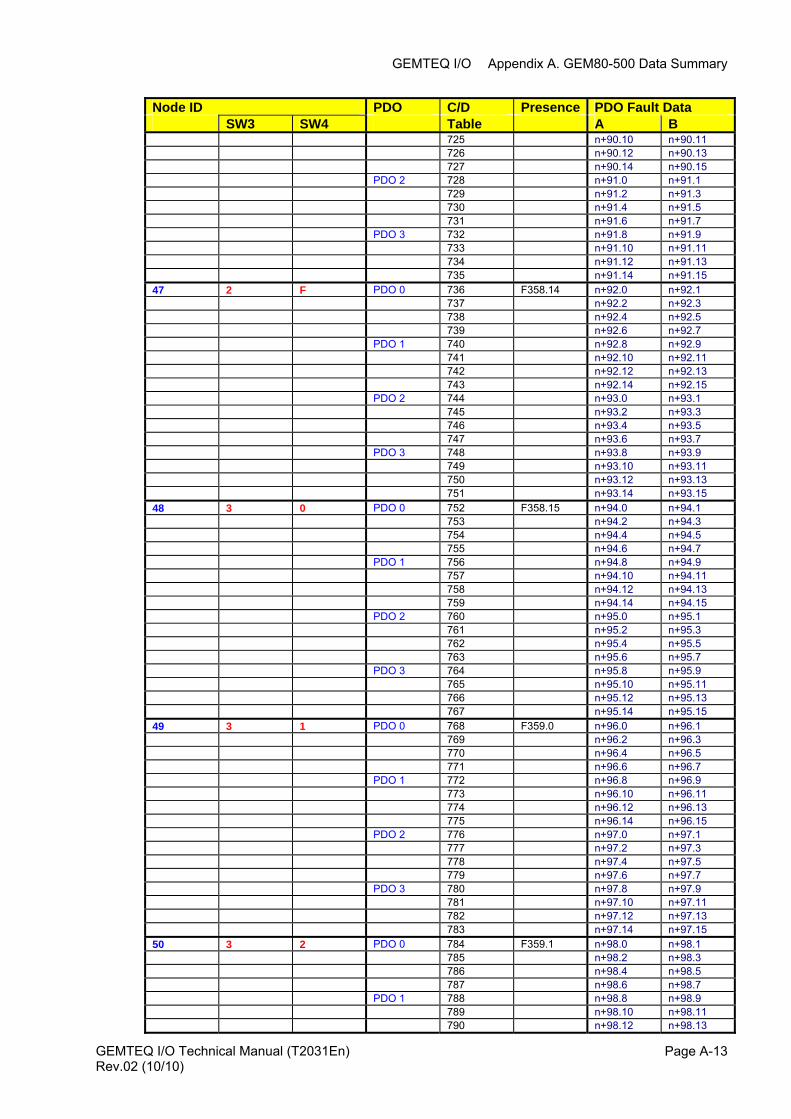
GEMTEQ I/O Appendix A. GEM80-500 Data Summary
Node ID PDO C/D Presence PDO Fault Data SW3 SW4 Table A B 725 n+90.10 n+90.11 726 n+90.12 n+90.13 727 n+90.14 n+90.15 PDO 2 728 n+91.0 n+91.1 729 n+91.2 n+91.3 730 n+91.4 n+91.5 731 n+91.6 n+91.7 PDO 3 732 n+91.8 n+91.9 733 n+91.10 n+91.11 734 n+91.12 n+91.13 735 n+91.14 n+91.15 47 2 F PDO 0 736 F358.14 n+92.0 n+92.1 737 n+92.2 n+92.3 738 n+92.4 n+92.5 739 n+92.6 n+92.7 PDO 1 740 n+92.8 n+92.9 741 n+92.10 n+92.11 742 n+92.12 n+92.13 743 n+92.14 n+92.15 PDO 2 744 n+93.0 n+93.1 745 n+93.2 n+93.3 746 n+93.4 n+93.5 747 n+93.6 n+93.7 PDO 3 748 n+93.8 n+93.9 749 n+93.10 n+93.11 750 n+93.12 n+93.13 751 n+93.14 n+93.15 48 3 0 PDO 0 752 F358.15 n+94.0 n+94.1 753 n+94.2 n+94.3 754 n+94.4 n+94.5 755 n+94.6 n+94.7 PDO 1 756 n+94.8 n+94.9 757 n+94.10 n+94.11 758 n+94.12 n+94.13 759 n+94.14 n+94.15 PDO 2 760 n+95.0 n+95.1 761 n+95.2 n+95.3 762 n+95.4 n+95.5 763 n+95.6 n+95.7 PDO 3 764 n+95.8 n+95.9 765 n+95.10 n+95.11 766 n+95.12 n+95.13 767 n+95.14 n+95.15 49 3 1 PDO 0 768 F359.0 n+96.0 n+96.1 769 n+96.2 n+96.3 770 n+96.4 n+96.5 771 n+96.6 n+96.7 PDO 1 772 n+96.8 n+96.9 773 n+96.10 n+96.11 774 n+96.12 n+96.13 775 n+96.14 n+96.15 PDO 2 776 n+97.0 n+97.1 777 n+97.2 n+97.3 778 n+97.4 n+97.5 779 n+97.6 n+97.7 PDO 3 780 n+97.8 n+97.9 781 n+97.10 n+97.11 782 n+97.12 n+97.13 783 n+97.14 n+97.15 50 3 2 PDO 0 784 F359.1 n+98.0 n+98.1 785 n+98.2 n+98.3 786 n+98.4 n+98.5 787 n+98.6 n+98.7 PDO 1 788 n+98.8 n+98.9 789 n+98.10 n+98.11 790 n+98.12 n+98.13
GEMTEQ I/O Technical Manual (T2031En) Page A-13Rev.02 (10/10)
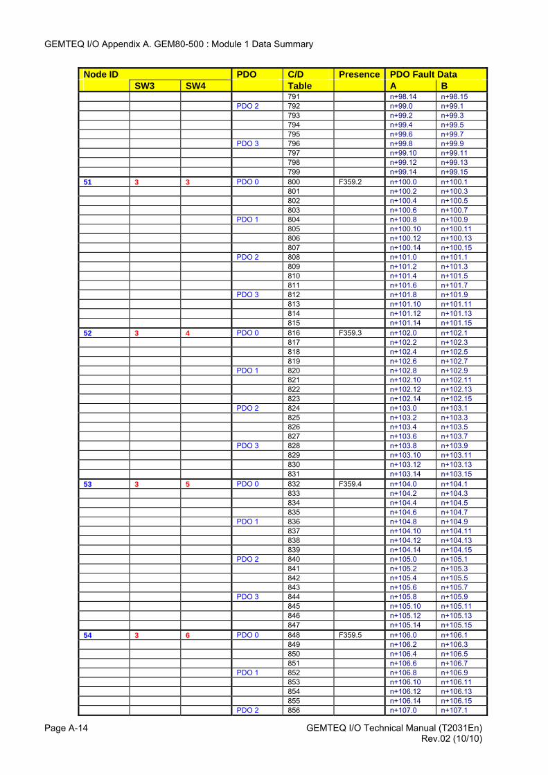
GEMTEQ I/O Appendix A. GEM80-500 : Module 1 Data Summary
GEMTEQ I/O Technical Manual (T2031En) Page A-14
Node ID PDO C/D Presence PDO Fault Data SW3 SW4 Table A B 791 n+98.14 n+98.15 PDO 2 792 n+99.0 n+99.1 793 n+99.2 n+99.3 794 n+99.4 n+99.5 795 n+99.6 n+99.7 PDO 3 796 n+99.8 n+99.9 797 n+99.10 n+99.11 798 n+99.12 n+99.13 799 n+99.14 n+99.15 51 3 3 PDO 0 800 F359.2 n+100.0 n+100.1 801 n+100.2 n+100.3 802 n+100.4 n+100.5 803 n+100.6 n+100.7 PDO 1 804 n+100.8 n+100.9 805 n+100.10 n+100.11 806 n+100.12 n+100.13 807 n+100.14 n+100.15 PDO 2 808 n+101.0 n+101.1 809 n+101.2 n+101.3 810 n+101.4 n+101.5 811 n+101.6 n+101.7 PDO 3 812 n+101.8 n+101.9 813 n+101.10 n+101.11 814 n+101.12 n+101.13 815 n+101.14 n+101.15 52 3 4 PDO 0 816 F359.3 n+102.0 n+102.1 817 n+102.2 n+102.3 818 n+102.4 n+102.5 819 n+102.6 n+102.7 PDO 1 820 n+102.8 n+102.9 821 n+102.10 n+102.11 822 n+102.12 n+102.13 823 n+102.14 n+102.15 PDO 2 824 n+103.0 n+103.1 825 n+103.2 n+103.3 826 n+103.4 n+103.5 827 n+103.6 n+103.7 PDO 3 828 n+103.8 n+103.9 829 n+103.10 n+103.11 830 n+103.12 n+103.13 831 n+103.14 n+103.15 53 3 5 PDO 0 832 F359.4 n+104.0 n+104.1 833 n+104.2 n+104.3 834 n+104.4 n+104.5 835 n+104.6 n+104.7 PDO 1 836 n+104.8 n+104.9 837 n+104.10 n+104.11 838 n+104.12 n+104.13 839 n+104.14 n+104.15 PDO 2 840 n+105.0 n+105.1 841 n+105.2 n+105.3 842 n+105.4 n+105.5 843 n+105.6 n+105.7 PDO 3 844 n+105.8 n+105.9 845 n+105.10 n+105.11 846 n+105.12 n+105.13 847 n+105.14 n+105.15 54 3 6 PDO 0 848 F359.5 n+106.0 n+106.1 849 n+106.2 n+106.3 850 n+106.4 n+106.5 851 n+106.6 n+106.7 PDO 1 852 n+106.8 n+106.9 853 n+106.10 n+106.11 854 n+106.12 n+106.13 855 n+106.14 n+106.15 PDO 2 856 n+107.0 n+107.1
Rev.02 (10/10)
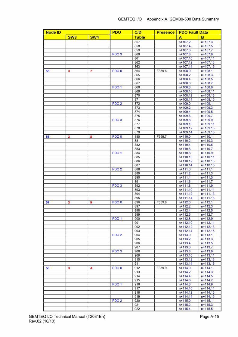
GEMTEQ I/O Appendix A. GEM80-500 Data Summary
GEMTEQ I/O Technical Manual (T2031En) Page A-15
Node ID PDO C/D Presence PDO Fault Data SW3 SW4 Table A B 857 n+107.2 n+107.3 858 n+107.4 n+107.5 859 n+107.6 n+107.7 PDO 3 860 n+107.8 n+107.9 861 n+107.10 n+107.11 862 n+107.12 n+107.13 863 n+107.14 n+107.15 55 3 7 PDO 0 864 F359.6 n+108.0 n+108.1 865 n+108.2 n+108.3 866 n+108.4 n+108.5 867 n+108.6 n+108.7 PDO 1 868 n+108.8 n+108.9 869 n+108.10 n+108.11 870 n+108.12 n+108.13 871 n+108.14 n+108.15 PDO 2 872 n+109.0 n+109.1 873 n+109.2 n+109.3 874 n+109.4 n+109.5 875 n+109.6 n+109.7 PDO 3 876 n+109.8 n+109.9 877 n+109.10 n+109.11 878 n+109.12 n+109.13 879 n+109.14 n+109.15 56 3 8 PDO 0 880 F359.7 n+110.0 n+110.1 881 n+110.2 n+110.3 882 n+110.4 n+110.5 883 n+110.6 n+110.7 PDO 1 884 n+110.8 n+110.9 885 n+110.10 n+110.11 886 n+110.12 n+110.13 887 n+110.14 n+110.15 PDO 2 888 n+111.0 n+111.1 889 n+111.2 n+111.3 890 n+111.4 n+111.5 891 n+111.6 n+111.7 PDO 3 892 n+111.8 n+111.9 893 n+111.10 n+111.11 894 n+111.12 n+111.13 895 n+111.14 n+111.15 57 3 9 PDO 0 896 F359.8 n+112.0 n+112.1 897 n+112.2 n+112.3 898 n+112.4 n+112.5 899 n+112.6 n+112.7 PDO 1 900 n+112.8 n+112.9 901 n+112.10 n+112.11 902 n+112.12 n+112.13 903 n+112.14 n+112.15 PDO 2 904 n+113.0 n+113.1 905 n+113.2 n+113.3 906 n+113.4 n+113.5 907 n+113.6 n+113.7 PDO 3 908 n+113.8 n+113.9 909 n+113.10 n+113.11 910 n+113.12 n+113.13 911 n+113.14 n+113.15 58 3 A PDO 0 912 F359.9 n+114.0 n+114.1 913 n+114.2 n+114.3 914 n+114.4 n+114.5 915 n+114.6 n+114.7 PDO 1 916 n+114.8 n+114.9 917 n+114.10 n+114.11 918 n+114.12 n+114.13 919 n+114.14 n+114.15 PDO 2 920 n+115.0 n+115.1 921 n+115.2 n+115.3 922 n+115.4 n+115.5
Rev.02 (10/10)
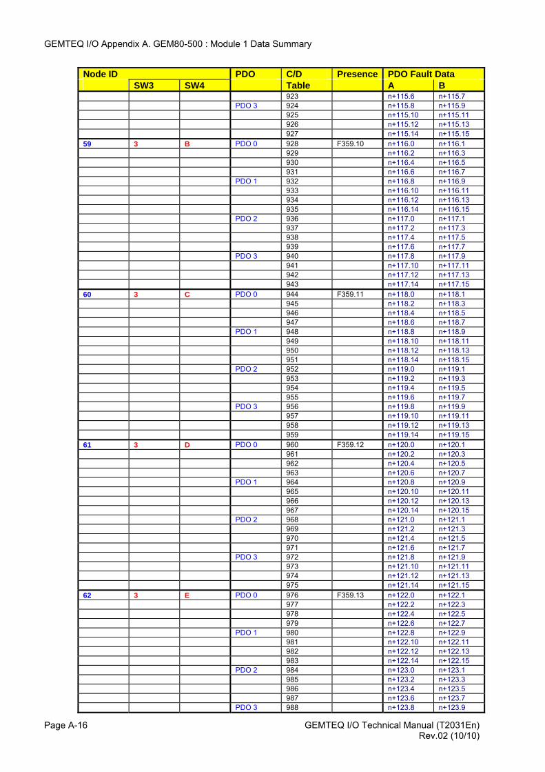
GEMTEQ I/O Appendix A. GEM80-500 : Module 1 Data Summary
GEMTEQ I/O Technical Manual (T2031En) Page A-16
Node ID PDO C/D Presence PDO Fault Data SW3 SW4 Table A B 923 n+115.6 n+115.7 PDO 3 924 n+115.8 n+115.9 925 n+115.10 n+115.11 926 n+115.12 n+115.13 927 n+115.14 n+115.15 59 3 B PDO 0 928 F359.10 n+116.0 n+116.1 929 n+116.2 n+116.3 930 n+116.4 n+116.5 931 n+116.6 n+116.7 PDO 1 932 n+116.8 n+116.9 933 n+116.10 n+116.11 934 n+116.12 n+116.13 935 n+116.14 n+116.15 PDO 2 936 n+117.0 n+117.1 937 n+117.2 n+117.3 938 n+117.4 n+117.5 939 n+117.6 n+117.7 PDO 3 940 n+117.8 n+117.9 941 n+117.10 n+117.11 942 n+117.12 n+117.13 943 n+117.14 n+117.15 60 3 C PDO 0 944 F359.11 n+118.0 n+118.1 945 n+118.2 n+118.3 946 n+118.4 n+118.5 947 n+118.6 n+118.7 PDO 1 948 n+118.8 n+118.9 949 n+118.10 n+118.11 950 n+118.12 n+118.13 951 n+118.14 n+118.15 PDO 2 952 n+119.0 n+119.1 953 n+119.2 n+119.3 954 n+119.4 n+119.5 955 n+119.6 n+119.7 PDO 3 956 n+119.8 n+119.9 957 n+119.10 n+119.11 958 n+119.12 n+119.13 959 n+119.14 n+119.15 61 3 D PDO 0 960 F359.12 n+120.0 n+120.1 961 n+120.2 n+120.3 962 n+120.4 n+120.5 963 n+120.6 n+120.7 PDO 1 964 n+120.8 n+120.9 965 n+120.10 n+120.11 966 n+120.12 n+120.13 967 n+120.14 n+120.15 PDO 2 968 n+121.0 n+121.1 969 n+121.2 n+121.3 970 n+121.4 n+121.5 971 n+121.6 n+121.7 PDO 3 972 n+121.8 n+121.9 973 n+121.10 n+121.11 974 n+121.12 n+121.13 975 n+121.14 n+121.15 62 3 E PDO 0 976 F359.13 n+122.0 n+122.1 977 n+122.2 n+122.3 978 n+122.4 n+122.5 979 n+122.6 n+122.7 PDO 1 980 n+122.8 n+122.9 981 n+122.10 n+122.11 982 n+122.12 n+122.13 983 n+122.14 n+122.15 PDO 2 984 n+123.0 n+123.1 985 n+123.2 n+123.3 986 n+123.4 n+123.5 987 n+123.6 n+123.7 PDO 3 988 n+123.8 n+123.9
Rev.02 (10/10)
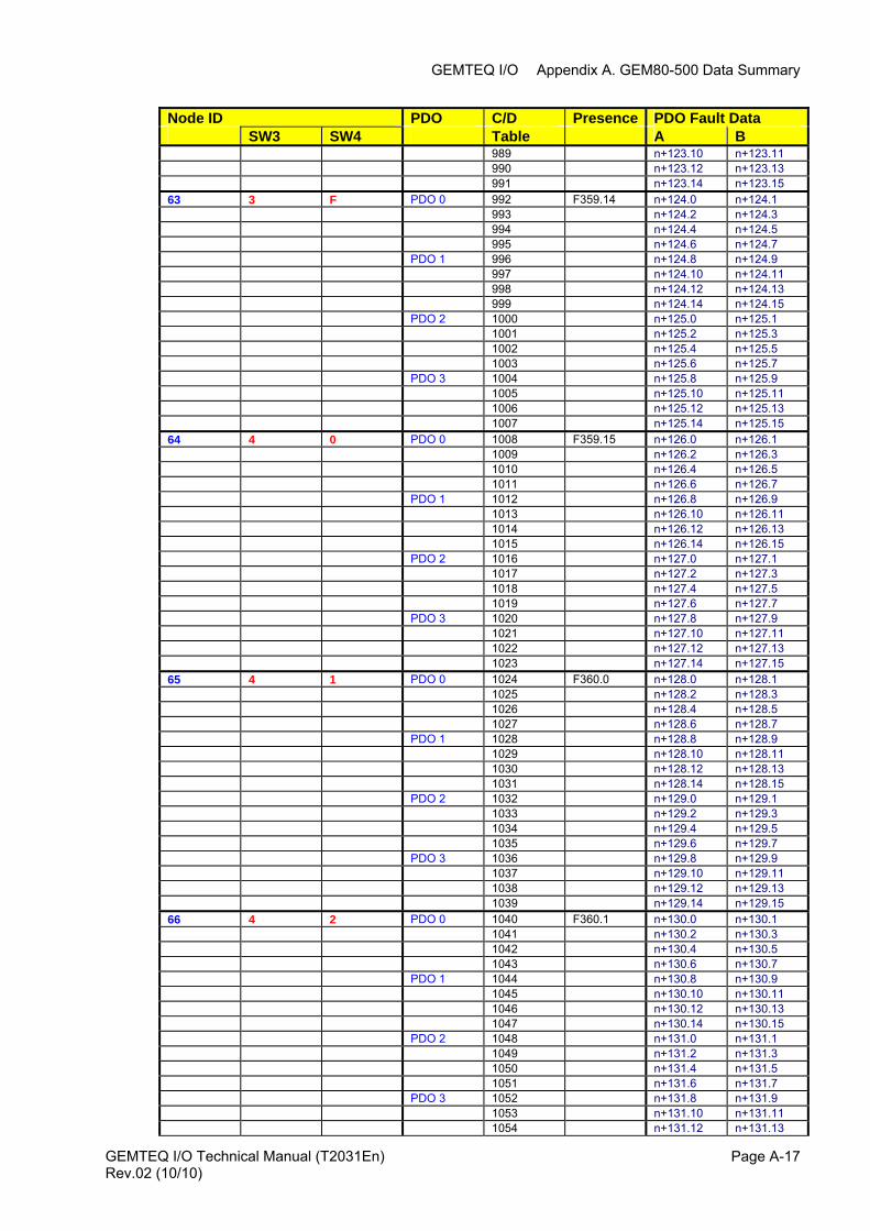
GEMTEQ I/O Appendix A. GEM80-500 Data Summary
GEMTEQ I/O Technical Manual (T2031En) Page A-17
Node ID PDO C/D Presence PDO Fault Data SW3 SW4 Table A B 989 n+123.10 n+123.11 990 n+123.12 n+123.13 991 n+123.14 n+123.15 63 3 F PDO 0 992 F359.14 n+124.0 n+124.1 993 n+124.2 n+124.3 994 n+124.4 n+124.5 995 n+124.6 n+124.7 PDO 1 996 n+124.8 n+124.9 997 n+124.10 n+124.11 998 n+124.12 n+124.13 999 n+124.14 n+124.15 PDO 2 1000 n+125.0 n+125.1 1001 n+125.2 n+125.3 1002 n+125.4 n+125.5 1003 n+125.6 n+125.7 PDO 3 1004 n+125.8 n+125.9 1005 n+125.10 n+125.11 1006 n+125.12 n+125.13 1007 n+125.14 n+125.15 64 4 0 PDO 0 1008 F359.15 n+126.0 n+126.1 1009 n+126.2 n+126.3 1010 n+126.4 n+126.5 1011 n+126.6 n+126.7 PDO 1 1012 n+126.8 n+126.9 1013 n+126.10 n+126.11 1014 n+126.12 n+126.13 1015 n+126.14 n+126.15 PDO 2 1016 n+127.0 n+127.1 1017 n+127.2 n+127.3 1018 n+127.4 n+127.5 1019 n+127.6 n+127.7 PDO 3 1020 n+127.8 n+127.9 1021 n+127.10 n+127.11 1022 n+127.12 n+127.13 1023 n+127.14 n+127.15 65 4 1 PDO 0 1024 F360.0 n+128.0 n+128.1 1025 n+128.2 n+128.3 1026 n+128.4 n+128.5 1027 n+128.6 n+128.7 PDO 1 1028 n+128.8 n+128.9 1029 n+128.10 n+128.11 1030 n+128.12 n+128.13 1031 n+128.14 n+128.15 PDO 2 1032 n+129.0 n+129.1 1033 n+129.2 n+129.3 1034 n+129.4 n+129.5 1035 n+129.6 n+129.7 PDO 3 1036 n+129.8 n+129.9 1037 n+129.10 n+129.11 1038 n+129.12 n+129.13 1039 n+129.14 n+129.15 66 4 2 PDO 0 1040 F360.1 n+130.0 n+130.1 1041 n+130.2 n+130.3 1042 n+130.4 n+130.5 1043 n+130.6 n+130.7 PDO 1 1044 n+130.8 n+130.9 1045 n+130.10 n+130.11 1046 n+130.12 n+130.13 1047 n+130.14 n+130.15 PDO 2 1048 n+131.0 n+131.1 1049 n+131.2 n+131.3 1050 n+131.4 n+131.5 1051 n+131.6 n+131.7 PDO 3 1052 n+131.8 n+131.9 1053 n+131.10 n+131.11 1054 n+131.12 n+131.13
Rev.02 (10/10)
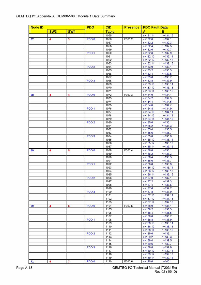
GEMTEQ I/O Appendix A. GEM80-500 : Module 1 Data Summary
GEMTEQ I/O Technical Manual (T2031En) Page A-18
Node ID PDO C/D Presence PDO Fault Data SW3 SW4 Table A B 1055 n+131.14 n+131.15 67 4 3 PDO 0 1056 F360.2 n+132.0 n+132.1 1057 n+132.2 n+132.3 1058 n+132.4 n+132.5 1059 n+132.6 n+132.7 PDO 1 1060 n+132.8 n+132.9 1061 n+132.10 n+132.11 1062 n+132.12 n+132.13 1063 n+132.14 n+132.15 PDO 2 1064 n+133.0 n+133.1 1065 n+133.2 n+133.3 1066 n+133.4 n+133.5 1067 n+133.6 n+133.7 PDO 3 1068 n+133.8 n+133.9 1069 n+133.10 n+133.11 1070 n+133.12 n+133.13 1071 n+133.14 n+133.15 68 4 4 PDO 0 1072 F360.3 n+134.0 n+134.1 1073 n+134.2 n+134.3 1074 n+134.4 n+134.5 1075 n+134.6 n+134.7 PDO 1 1076 n+134.8 n+134.9 1077 n+134.10 n+134.11 1078 n+134.12 n+134.13 1079 n+134.14 n+134.15 PDO 2 1080 n+135.0 n+135.1 1081 n+135.2 n+135.3 1082 n+135.4 n+135.5 1083 n+135.6 n+135.7 PDO 3 1084 n+135.8 n+135.9 1085 n+135.10 n+135.11 1086 n+135.12 n+135.13 1087 n+135.14 n+135.15 69 4 5 PDO 0 1088 F360.4 n+136.0 n+136.1 1089 n+136.2 n+136.3 1090 n+136.4 n+136.5 1091 n+136.6 n+136.7 PDO 1 1092 n+136.8 n+136.9 1093 n+136.10 n+136.11 1094 n+136.12 n+136.13 1095 n+136.14 n+136.15 PDO 2 1096 n+137.0 n+137.1 1097 n+137.2 n+137.3 1098 n+137.4 n+137.5 1099 n+137.6 n+137.7 PDO 3 1100 n+137.8 n+137.9 1101 n+137.10 n+137.11 1102 n+137.12 n+137.13 1103 n+137.14 n+137.15 70 4 6 PDO 0 1104 F360.5 n+138.0 n+138.1 1105 n+138.2 n+138.3 1106 n+138.4 n+138.5 1107 n+138.6 n+138.7 PDO 1 1108 n+138.8 n+138.9 1109 n+138.10 n+138.11 1110 n+138.12 n+138.13 1111 n+138.14 n+138.15 PDO 2 1112 n+139.0 n+139.1 1113 n+139.2 n+139.3 1114 n+139.4 n+139.5 1115 n+139.6 n+139.7 PDO 3 1116 n+139.8 n+139.9 1117 n+139.10 n+139.11 1118 n+139.12 n+139.13 1119 n+139.14 n+139.15 71 4 7 PDO 0 1120 F360.6 n+140.0 n+140.1
Rev.02 (10/10)
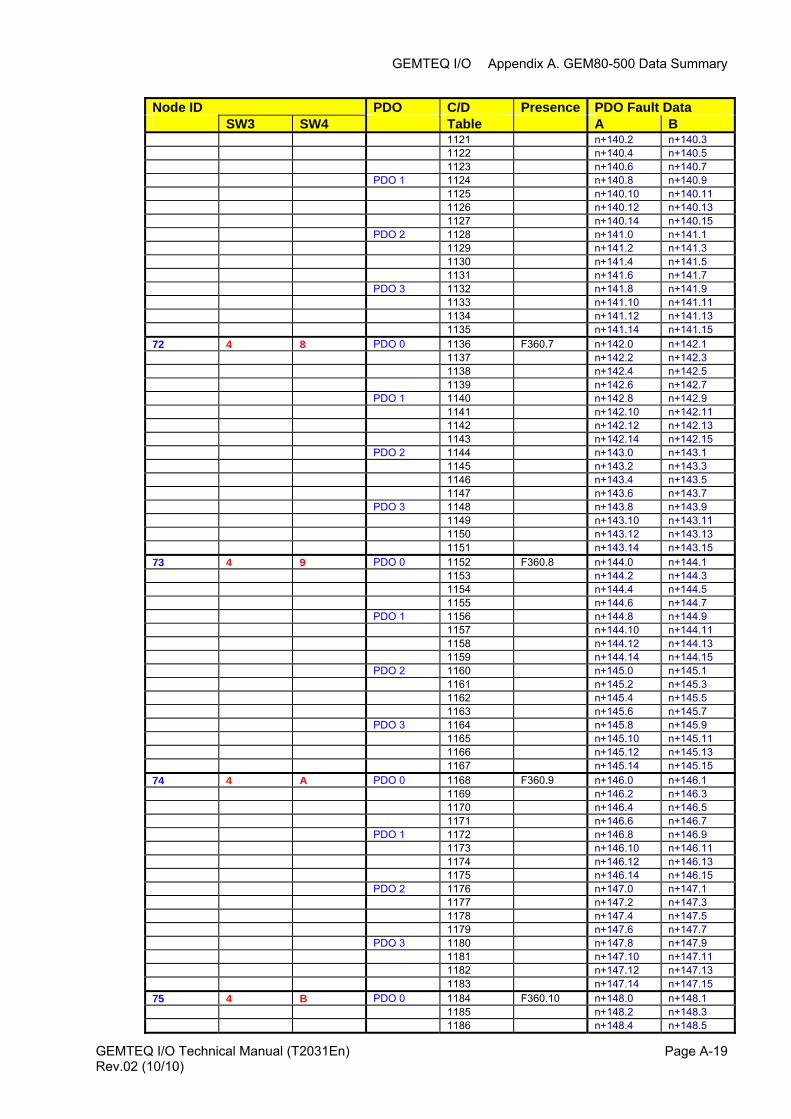
GEMTEQ I/O Appendix A. GEM80-500 Data Summary
GEMTEQ I/O Technical Manual (T2031En) Page A-19
Node ID PDO C/D Presence PDO Fault Data SW3 SW4 Table A B 1121 n+140.2 n+140.3 1122 n+140.4 n+140.5 1123 n+140.6 n+140.7 PDO 1 1124 n+140.8 n+140.9 1125 n+140.10 n+140.11 1126 n+140.12 n+140.13 1127 n+140.14 n+140.15 PDO 2 1128 n+141.0 n+141.1 1129 n+141.2 n+141.3 1130 n+141.4 n+141.5 1131 n+141.6 n+141.7 PDO 3 1132 n+141.8 n+141.9 1133 n+141.10 n+141.11 1134 n+141.12 n+141.13 1135 n+141.14 n+141.15 72 4 8 PDO 0 1136 F360.7 n+142.0 n+142.1 1137 n+142.2 n+142.3 1138 n+142.4 n+142.5 1139 n+142.6 n+142.7 PDO 1 1140 n+142.8 n+142.9 1141 n+142.10 n+142.11 1142 n+142.12 n+142.13 1143 n+142.14 n+142.15 PDO 2 1144 n+143.0 n+143.1 1145 n+143.2 n+143.3 1146 n+143.4 n+143.5 1147 n+143.6 n+143.7 PDO 3 1148 n+143.8 n+143.9 1149 n+143.10 n+143.11 1150 n+143.12 n+143.13 1151 n+143.14 n+143.15 73 4 9 PDO 0 1152 F360.8 n+144.0 n+144.1 1153 n+144.2 n+144.3 1154 n+144.4 n+144.5 1155 n+144.6 n+144.7 PDO 1 1156 n+144.8 n+144.9 1157 n+144.10 n+144.11 1158 n+144.12 n+144.13 1159 n+144.14 n+144.15 PDO 2 1160 n+145.0 n+145.1 1161 n+145.2 n+145.3 1162 n+145.4 n+145.5 1163 n+145.6 n+145.7 PDO 3 1164 n+145.8 n+145.9 1165 n+145.10 n+145.11 1166 n+145.12 n+145.13 1167 n+145.14 n+145.15 74 4 A PDO 0 1168 F360.9 n+146.0 n+146.1 1169 n+146.2 n+146.3 1170 n+146.4 n+146.5 1171 n+146.6 n+146.7 PDO 1 1172 n+146.8 n+146.9 1173 n+146.10 n+146.11 1174 n+146.12 n+146.13 1175 n+146.14 n+146.15 PDO 2 1176 n+147.0 n+147.1 1177 n+147.2 n+147.3 1178 n+147.4 n+147.5 1179 n+147.6 n+147.7 PDO 3 1180 n+147.8 n+147.9 1181 n+147.10 n+147.11 1182 n+147.12 n+147.13 1183 n+147.14 n+147.15 75 4 B PDO 0 1184 F360.10 n+148.0 n+148.1 1185 n+148.2 n+148.3 1186 n+148.4 n+148.5
Rev.02 (10/10)
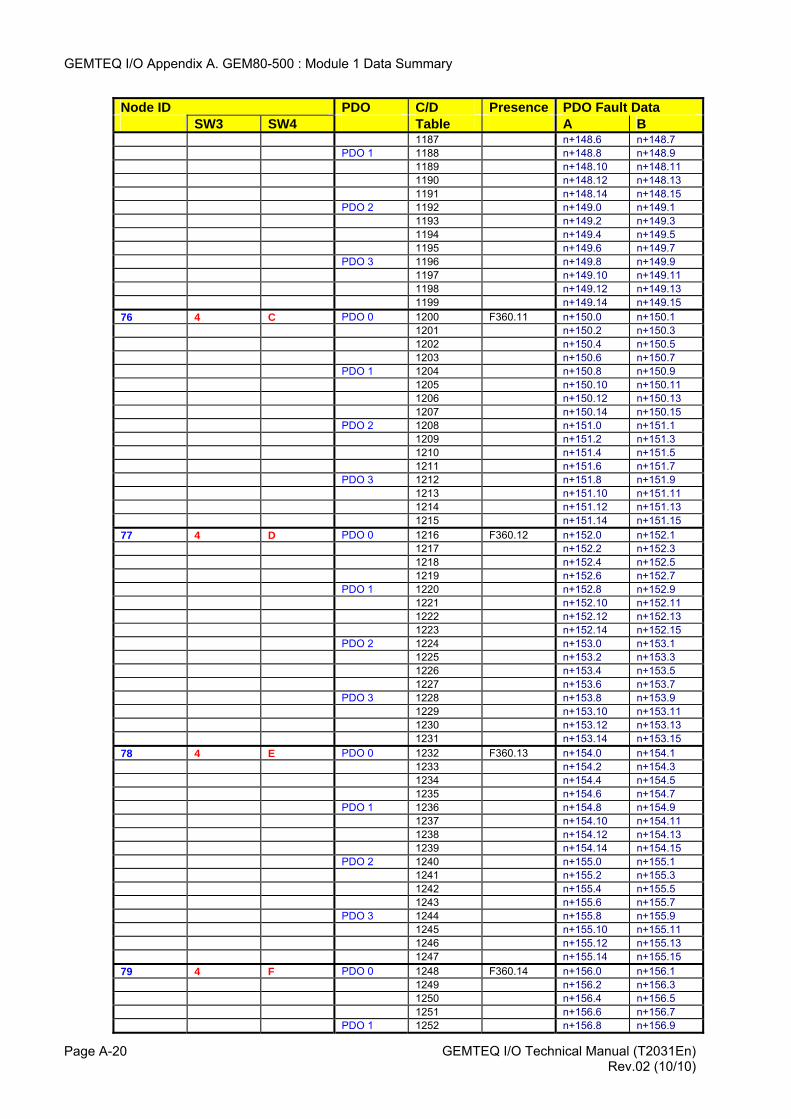
GEMTEQ I/O Appendix A. GEM80-500 : Module 1 Data Summary
GEMTEQ I/O Technical Manual (T2031En) Page A-20
Node ID PDO C/D Presence PDO Fault Data SW3 SW4 Table A B 1187 n+148.6 n+148.7 PDO 1 1188 n+148.8 n+148.9 1189 n+148.10 n+148.11 1190 n+148.12 n+148.13 1191 n+148.14 n+148.15 PDO 2 1192 n+149.0 n+149.1 1193 n+149.2 n+149.3 1194 n+149.4 n+149.5 1195 n+149.6 n+149.7 PDO 3 1196 n+149.8 n+149.9 1197 n+149.10 n+149.11 1198 n+149.12 n+149.13 1199 n+149.14 n+149.15 76 4 C PDO 0 1200 F360.11 n+150.0 n+150.1 1201 n+150.2 n+150.3 1202 n+150.4 n+150.5 1203 n+150.6 n+150.7 PDO 1 1204 n+150.8 n+150.9 1205 n+150.10 n+150.11 1206 n+150.12 n+150.13 1207 n+150.14 n+150.15 PDO 2 1208 n+151.0 n+151.1 1209 n+151.2 n+151.3 1210 n+151.4 n+151.5 1211 n+151.6 n+151.7 PDO 3 1212 n+151.8 n+151.9 1213 n+151.10 n+151.11 1214 n+151.12 n+151.13 1215 n+151.14 n+151.15 77 4 D PDO 0 1216 F360.12 n+152.0 n+152.1 1217 n+152.2 n+152.3 1218 n+152.4 n+152.5 1219 n+152.6 n+152.7 PDO 1 1220 n+152.8 n+152.9 1221 n+152.10 n+152.11 1222 n+152.12 n+152.13 1223 n+152.14 n+152.15 PDO 2 1224 n+153.0 n+153.1 1225 n+153.2 n+153.3 1226 n+153.4 n+153.5 1227 n+153.6 n+153.7 PDO 3 1228 n+153.8 n+153.9 1229 n+153.10 n+153.11 1230 n+153.12 n+153.13 1231 n+153.14 n+153.15 78 4 E PDO 0 1232 F360.13 n+154.0 n+154.1 1233 n+154.2 n+154.3 1234 n+154.4 n+154.5 1235 n+154.6 n+154.7 PDO 1 1236 n+154.8 n+154.9 1237 n+154.10 n+154.11 1238 n+154.12 n+154.13 1239 n+154.14 n+154.15 PDO 2 1240 n+155.0 n+155.1 1241 n+155.2 n+155.3 1242 n+155.4 n+155.5 1243 n+155.6 n+155.7 PDO 3 1244 n+155.8 n+155.9 1245 n+155.10 n+155.11 1246 n+155.12 n+155.13 1247 n+155.14 n+155.15 79 4 F PDO 0 1248 F360.14 n+156.0 n+156.1 1249 n+156.2 n+156.3 1250 n+156.4 n+156.5 1251 n+156.6 n+156.7 PDO 1 1252 n+156.8 n+156.9
Rev.02 (10/10)
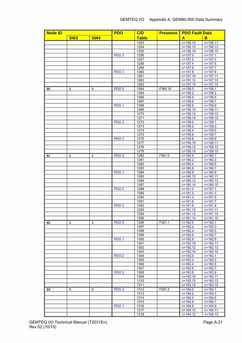
GEMTEQ I/O Appendix A. GEM80-500 Data Summary
GEMTEQ I/O Technical Manual (T2031En) Page A-21
Node ID PDO C/D Presence PDO Fault Data SW3 SW4 Table A B 1253 n+156.10 n+156.11 1254 n+156.12 n+156.13 1255 n+156.14 n+156.15 PDO 2 1256 n+157.0 n+157.1 1257 n+157.2 n+157.3 1258 n+157.4 n+157.5 1259 n+157.6 n+157.7 PDO 3 1260 n+157.8 n+157.9 1261 n+157.10 n+157.11 1262 n+157.12 n+157.13 1263 n+157.14 n+157.15 80 5 0 PDO 0 1264 F360.15 n+158.0 n+158.1 1265 n+158.2 n+158.3 1266 n+158.4 n+158.5 1267 n+158.6 n+158.7 PDO 1 1268 n+158.8 n+158.9 1269 n+158.10 n+158.11 1270 n+158.12 n+158.13 1271 n+158.14 n+158.15 PDO 2 1272 n+159.0 n+159.1 1273 n+159.2 n+159.3 1274 n+159.4 n+159.5 1275 n+159.6 n+159.7 PDO 3 1276 n+159.8 n+159.9 1277 n+159.10 n+159.11 1278 n+159.12 n+159.13 1279 n+159.14 n+159.15 81 5 1 PDO 0 1280 F361.0 n+160.0 n+160.1 1281 n+160.2 n+160.3 1282 n+160.4 n+160.5 1283 n+160.6 n+160.7 PDO 1 1284 n+160.8 n+160.9 1285 n+160.10 n+160.11 1286 n+160.12 n+160.13 1287 n+160.14 n+160.15 PDO 2 1288 n+161.0 n+161.1 1289 n+161.2 n+161.3 1290 n+161.4 n+161.5 1291 n+161.6 n+161.7 PDO 3 1292 n+161.8 n+161.9 1293 n+161.10 n+161.11 1294 n+161.12 n+161.13 1295 n+161.14 n+161.15 82 5 2 PDO 0 1296 F361.1 n+162.0 n+162.1 1297 n+162.2 n+162.3 1298 n+162.4 n+162.5 1299 n+162.6 n+162.7 PDO 1 1300 n+162.8 n+162.9 1301 n+162.10 n+162.11 1302 n+162.12 n+162.13 1303 n+162.14 n+162.15 PDO 2 1304 n+163.0 n+163.1 1305 n+163.2 n+163.3 1306 n+163.4 n+163.5 1307 n+163.6 n+163.7 PDO 3 1308 n+163.8 n+163.9 1309 n+163.10 n+163.11 1310 n+163.12 n+163.13 1311 n+163.14 n+163.15 83 5 3 PDO 0 1312 F361.2 n+164.0 n+164.1 1313 n+164.2 n+164.3 1314 n+164.4 n+164.5 1315 n+164.6 n+164.7 PDO 1 1316 n+164.8 n+164.9 1317 n+164.10 n+164.11 1318 n+164.12 n+164.13
Rev.02 (10/10)
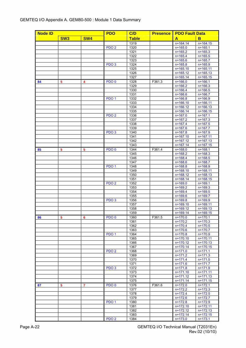
GEMTEQ I/O Appendix A. GEM80-500 : Module 1 Data Summary
Node ID PDO C/D Presence PDO Fault Data SW3 SW4 Table A B 1319 n+164.14 n+164.15 PDO 2 1320 n+165.0 n+165.1 1321 n+165.2 n+165.3 1322 n+165.4 n+165.5 1323 n+165.6 n+165.7 PDO 3 1324 n+165.8 n+165.9 1325 n+165.10 n+165.11 1326 n+165.12 n+165.13 1327 n+165.14 n+165.15 84 5 4 PDO 0 1328 F361.3 n+166.0 n+166.1 1329 n+166.2 n+166.3 1330 n+166.4 n+166.5 1331 n+166.6 n+166.7 PDO 1 1332 n+166.8 n+166.9 1333 n+166.10 n+166.11 1334 n+166.12 n+166.13 1335 n+166.14 n+166.15 PDO 2 1336 n+167.0 n+167.1 1337 n+167.2 n+167.3 1338 n+167.4 n+167.5 1339 n+167.6 n+167.7 PDO 3 1340 n+167.8 n+167.9 1341 n+167.10 n+167.11 1342 n+167.12 n+167.13 1343 n+167.14 n+167.15 85 5 5 PDO 0 1344 F361.4 n+168.0 n+168.1 1345 n+168.2 n+168.3 1346 n+168.4 n+168.5 1347 n+168.6 n+168.7 PDO 1 1348 n+168.8 n+168.9 1349 n+168.10 n+168.11 1350 n+168.12 n+168.13 1351 n+168.14 n+168.15 PDO 2 1352 n+169.0 n+169.1 1353 n+169.2 n+169.3 1354 n+169.4 n+169.5 1355 n+169.6 n+169.7 PDO 3 1356 n+169.8 n+169.9 1357 n+169.10 n+169.11 1358 n+169.12 n+169.13 1359 n+169.14 n+169.15 86 5 6 PDO 0 1360 F361.5 n+170.0 n+170.1 1361 n+170.2 n+170.3 1362 n+170.4 n+170.5 1363 n+170.6 n+170.7 PDO 1 1364 n+170.8 n+170.9 1365 n+170.10 n+170.11 1366 n+170.12 n+170.13 1367 n+170.14 n+170.15 PDO 2 1368 n+171.0 n+171.1 1369 n+171.2 n+171.3 1370 n+171.4 n+171.5 1371 n+171.6 n+171.7 PDO 3 1372 n+171.8 n+171.9 1373 n+171.10 n+171.11 1374 n+171.12 n+171.13 1375 n+171.14 n+171.15 87 5 7 PDO 0 1376 F361.6 n+172.0 n+172.1 1377 n+172.2 n+172.3 1378 n+172.4 n+172.5 1379 n+172.6 n+172.7 PDO 1 1380 n+172.8 n+172.9 1381 n+172.10 n+172.11 1382 n+172.12 n+172.13 1383 n+172.14 n+172.15 PDO 2 1384 n+173.0 n+173.1
GEMTEQ I/O Technical Manual (T2031En) Page A-22 Rev.02 (10/10)
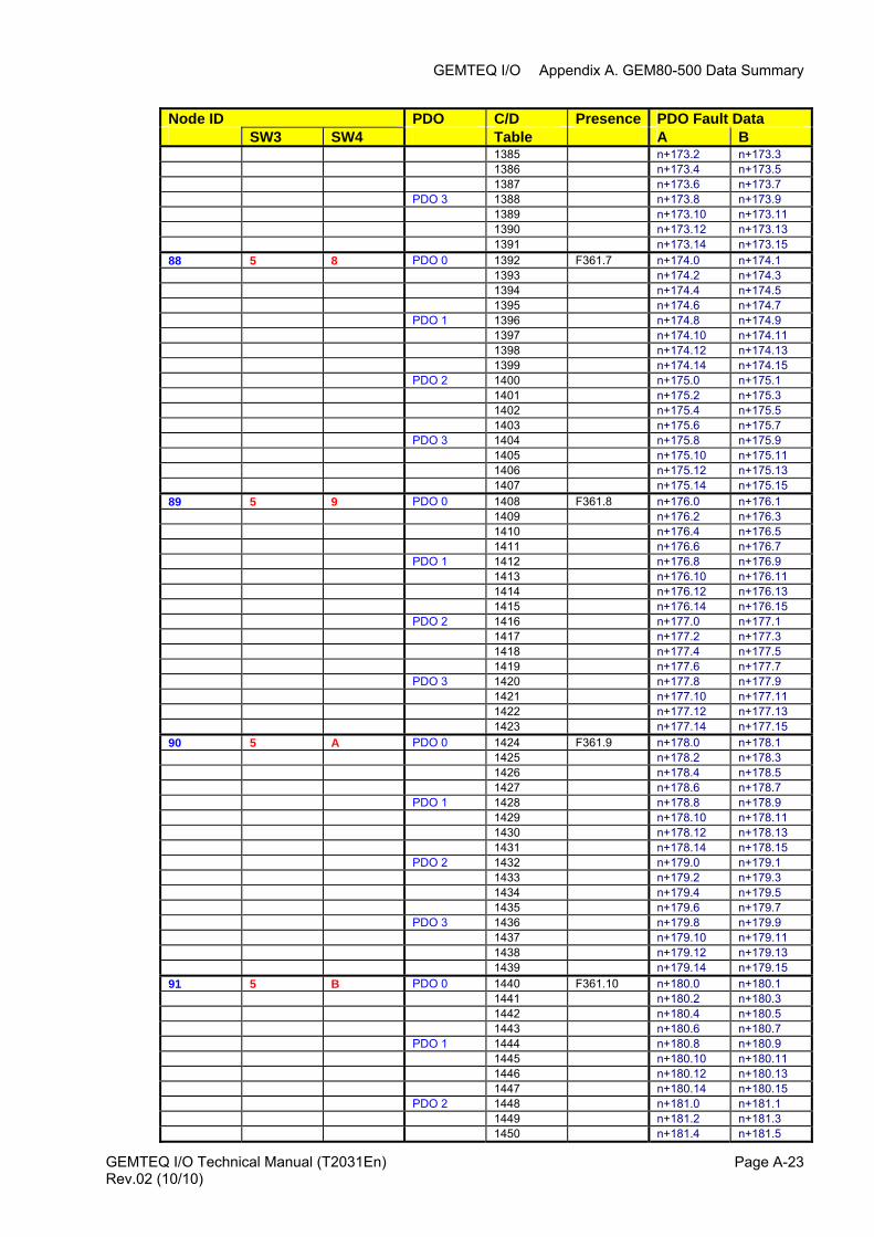
GEMTEQ I/O Appendix A. GEM80-500 Data Summary
Node ID PDO C/D Presence PDO Fault Data SW3 SW4 Table A B 1385 n+173.2 n+173.3 1386 n+173.4 n+173.5 1387 n+173.6 n+173.7 PDO 3 1388 n+173.8 n+173.9 1389 n+173.10 n+173.11 1390 n+173.12 n+173.13 1391 n+173.14 n+173.15 88 5 8 PDO 0 1392 F361.7 n+174.0 n+174.1 1393 n+174.2 n+174.3 1394 n+174.4 n+174.5 1395 n+174.6 n+174.7 PDO 1 1396 n+174.8 n+174.9 1397 n+174.10 n+174.11 1398 n+174.12 n+174.13 1399 n+174.14 n+174.15 PDO 2 1400 n+175.0 n+175.1 1401 n+175.2 n+175.3 1402 n+175.4 n+175.5 1403 n+175.6 n+175.7 PDO 3 1404 n+175.8 n+175.9 1405 n+175.10 n+175.11 1406 n+175.12 n+175.13 1407 n+175.14 n+175.15 89 5 9 PDO 0 1408 F361.8 n+176.0 n+176.1 1409 n+176.2 n+176.3 1410 n+176.4 n+176.5 1411 n+176.6 n+176.7 PDO 1 1412 n+176.8 n+176.9 1413 n+176.10 n+176.11 1414 n+176.12 n+176.13 1415 n+176.14 n+176.15 PDO 2 1416 n+177.0 n+177.1 1417 n+177.2 n+177.3 1418 n+177.4 n+177.5 1419 n+177.6 n+177.7 PDO 3 1420 n+177.8 n+177.9 1421 n+177.10 n+177.11 1422 n+177.12 n+177.13 1423 n+177.14 n+177.15 90 5 A PDO 0 1424 F361.9 n+178.0 n+178.1 1425 n+178.2 n+178.3 1426 n+178.4 n+178.5 1427 n+178.6 n+178.7 PDO 1 1428 n+178.8 n+178.9 1429 n+178.10 n+178.11 1430 n+178.12 n+178.13 1431 n+178.14 n+178.15 PDO 2 1432 n+179.0 n+179.1 1433 n+179.2 n+179.3 1434 n+179.4 n+179.5 1435 n+179.6 n+179.7 PDO 3 1436 n+179.8 n+179.9 1437 n+179.10 n+179.11 1438 n+179.12 n+179.13 1439 n+179.14 n+179.15 91 5 B PDO 0 1440 F361.10 n+180.0 n+180.1 1441 n+180.2 n+180.3 1442 n+180.4 n+180.5 1443 n+180.6 n+180.7 PDO 1 1444 n+180.8 n+180.9 1445 n+180.10 n+180.11 1446 n+180.12 n+180.13 1447 n+180.14 n+180.15 PDO 2 1448 n+181.0 n+181.1 1449 n+181.2 n+181.3 1450 n+181.4 n+181.5
GEMTEQ I/O Technical Manual (T2031En) Page A-23Rev.02 (10/10)
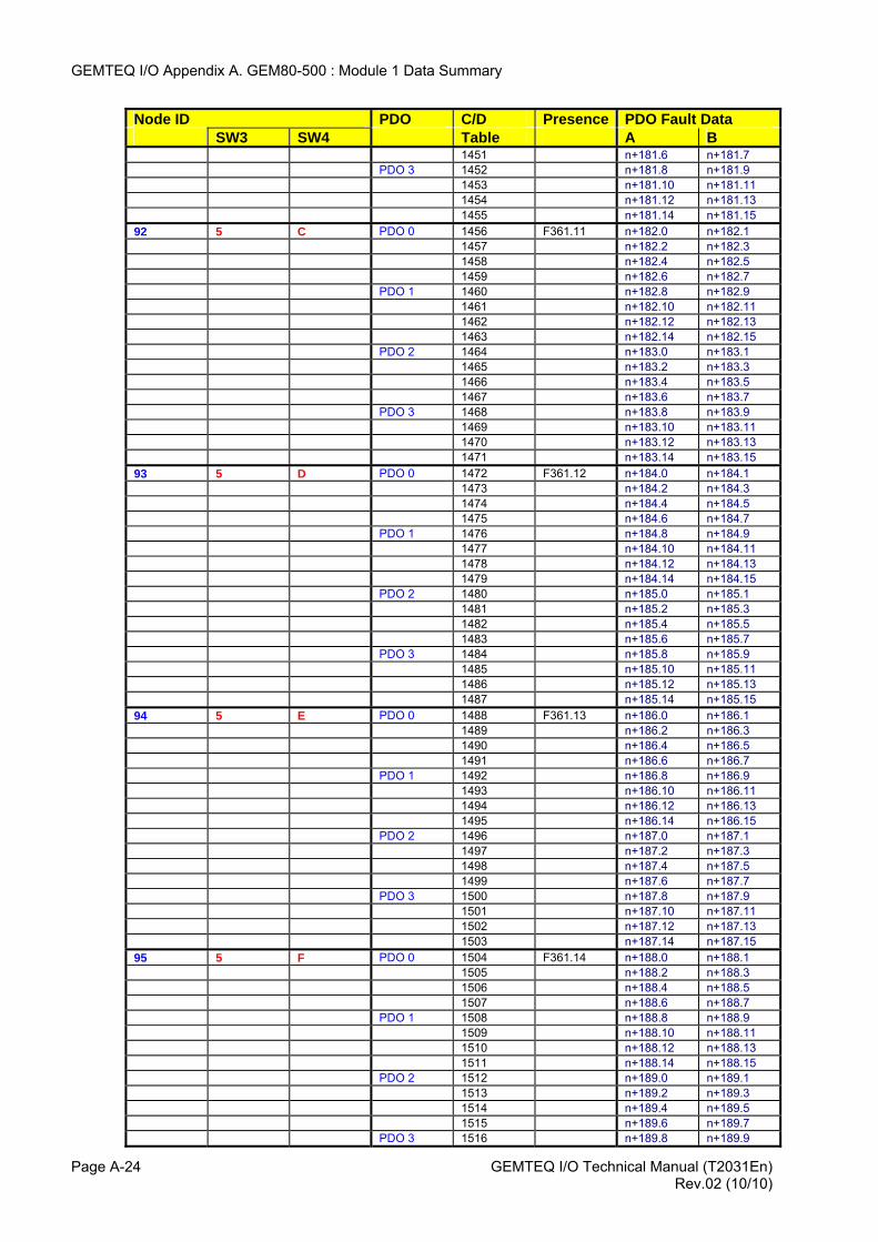
GEMTEQ I/O Appendix A. GEM80-500 : Module 1 Data Summary
Node ID PDO C/D Presence PDO Fault Data SW3 SW4 Table A B 1451 n+181.6 n+181.7 PDO 3 1452 n+181.8 n+181.9 1453 n+181.10 n+181.11 1454 n+181.12 n+181.13 1455 n+181.14 n+181.15 92 5 C PDO 0 1456 F361.11 n+182.0 n+182.1 1457 n+182.2 n+182.3 1458 n+182.4 n+182.5 1459 n+182.6 n+182.7 PDO 1 1460 n+182.8 n+182.9 1461 n+182.10 n+182.11 1462 n+182.12 n+182.13 1463 n+182.14 n+182.15 PDO 2 1464 n+183.0 n+183.1 1465 n+183.2 n+183.3 1466 n+183.4 n+183.5 1467 n+183.6 n+183.7 PDO 3 1468 n+183.8 n+183.9 1469 n+183.10 n+183.11 1470 n+183.12 n+183.13 1471 n+183.14 n+183.15 93 5 D PDO 0 1472 F361.12 n+184.0 n+184.1 1473 n+184.2 n+184.3 1474 n+184.4 n+184.5 1475 n+184.6 n+184.7 PDO 1 1476 n+184.8 n+184.9 1477 n+184.10 n+184.11 1478 n+184.12 n+184.13 1479 n+184.14 n+184.15 PDO 2 1480 n+185.0 n+185.1 1481 n+185.2 n+185.3 1482 n+185.4 n+185.5 1483 n+185.6 n+185.7 PDO 3 1484 n+185.8 n+185.9 1485 n+185.10 n+185.11 1486 n+185.12 n+185.13 1487 n+185.14 n+185.15 94 5 E PDO 0 1488 F361.13 n+186.0 n+186.1 1489 n+186.2 n+186.3 1490 n+186.4 n+186.5 1491 n+186.6 n+186.7 PDO 1 1492 n+186.8 n+186.9 1493 n+186.10 n+186.11 1494 n+186.12 n+186.13 1495 n+186.14 n+186.15 PDO 2 1496 n+187.0 n+187.1 1497 n+187.2 n+187.3 1498 n+187.4 n+187.5 1499 n+187.6 n+187.7 PDO 3 1500 n+187.8 n+187.9 1501 n+187.10 n+187.11 1502 n+187.12 n+187.13 1503 n+187.14 n+187.15 95 5 F PDO 0 1504 F361.14 n+188.0 n+188.1 1505 n+188.2 n+188.3 1506 n+188.4 n+188.5 1507 n+188.6 n+188.7 PDO 1 1508 n+188.8 n+188.9 1509 n+188.10 n+188.11 1510 n+188.12 n+188.13 1511 n+188.14 n+188.15 PDO 2 1512 n+189.0 n+189.1 1513 n+189.2 n+189.3 1514 n+189.4 n+189.5 1515 n+189.6 n+189.7 PDO 3 1516 n+189.8 n+189.9
GEMTEQ I/O Technical Manual (T2031En) Page A-24 Rev.02 (10/10)
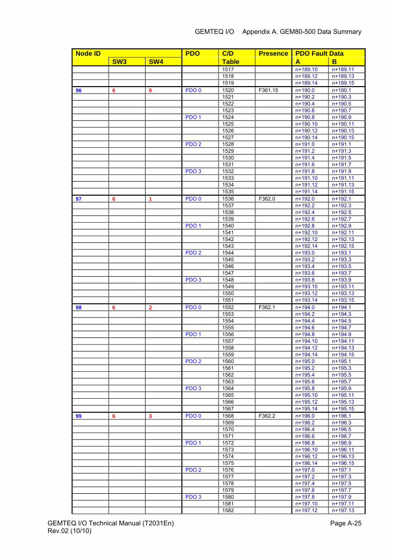
GEMTEQ I/O Appendix A. GEM80-500 Data Summary
Node ID PDO C/D Presence PDO Fault Data SW3 SW4 Table A B 1517 n+189.10 n+189.11 1518 n+189.12 n+189.13 1519 n+189.14 n+189.15 96 6 0 PDO 0 1520 F361.15 n+190.0 n+190.1 1521 n+190.2 n+190.3 1522 n+190.4 n+190.5 1523 n+190.6 n+190.7 PDO 1 1524 n+190.8 n+190.9 1525 n+190.10 n+190.11 1526 n+190.12 n+190.13 1527 n+190.14 n+190.15 PDO 2 1528 n+191.0 n+191.1 1529 n+191.2 n+191.3 1530 n+191.4 n+191.5 1531 n+191.6 n+191.7 PDO 3 1532 n+191.8 n+191.9 1533 n+191.10 n+191.11 1534 n+191.12 n+191.13 1535 n+191.14 n+191.15 97 6 1 PDO 0 1536 F362.0 n+192.0 n+192.1 1537 n+192.2 n+192.3 1538 n+192.4 n+192.5 1539 n+192.6 n+192.7 PDO 1 1540 n+192.8 n+192.9 1541 n+192.10 n+192.11 1542 n+192.12 n+192.13 1543 n+192.14 n+192.15 PDO 2 1544 n+193.0 n+193.1 1545 n+193.2 n+193.3 1546 n+193.4 n+193.5 1547 n+193.6 n+193.7 PDO 3 1548 n+193.8 n+193.9 1549 n+193.10 n+193.11 1550 n+193.12 n+193.13 1551 n+193.14 n+193.15 98 6 2 PDO 0 1552 F362.1 n+194.0 n+194.1 1553 n+194.2 n+194.3 1554 n+194.4 n+194.5 1555 n+194.6 n+194.7 PDO 1 1556 n+194.8 n+194.9 1557 n+194.10 n+194.11 1558 n+194.12 n+194.13 1559 n+194.14 n+194.15 PDO 2 1560 n+195.0 n+195.1 1561 n+195.2 n+195.3 1562 n+195.4 n+195.5 1563 n+195.6 n+195.7 PDO 3 1564 n+195.8 n+195.9 1565 n+195.10 n+195.11 1566 n+195.12 n+195.13 1567 n+195.14 n+195.15 99 6 3 PDO 0 1568 F362.2 n+196.0 n+196.1 1569 n+196.2 n+196.3 1570 n+196.4 n+196.5 1571 n+196.6 n+196.7 PDO 1 1572 n+196.8 n+196.9 1573 n+196.10 n+196.11 1574 n+196.12 n+196.13 1575 n+196.14 n+196.15 PDO 2 1576 n+197.0 n+197.1 1577 n+197.2 n+197.3 1578 n+197.4 n+197.5 1579 n+197.6 n+197.7 PDO 3 1580 n+197.8 n+197.9 1581 n+197.10 n+197.11 1582 n+197.12 n+197.13
GEMTEQ I/O Technical Manual (T2031En) Page A-25Rev.02 (10/10)
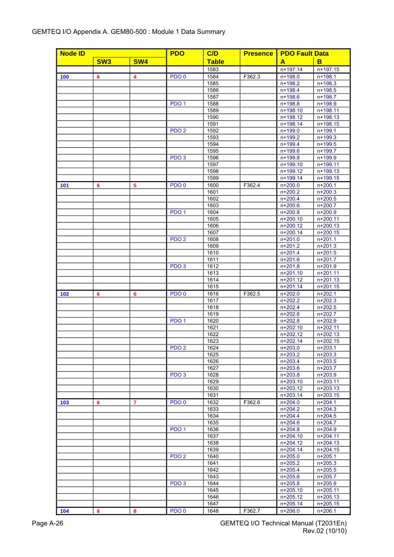
GEMTEQ I/O Appendix A. GEM80-500 : Module 1 Data Summary
Node ID PDO C/D Presence PDO Fault Data SW3 SW4 Table A B 1583 n+197.14 n+197.15 100 6 4 PDO 0 1584 F362.3 n+198.0 n+198.1 1585 n+198.2 n+198.3 1586 n+198.4 n+198.5 1587 n+198.6 n+198.7 PDO 1 1588 n+198.8 n+198.9 1589 n+198.10 n+198.11 1590 n+198.12 n+198.13 1591 n+198.14 n+198.15 PDO 2 1592 n+199.0 n+199.1 1593 n+199.2 n+199.3 1594 n+199.4 n+199.5 1595 n+199.6 n+199.7 PDO 3 1596 n+199.8 n+199.9 1597 n+199.10 n+199.11 1598 n+199.12 n+199.13 1599 n+199.14 n+199.15 101 6 5 PDO 0 1600 F362.4 n+200.0 n+200.1 1601 n+200.2 n+200.3 1602 n+200.4 n+200.5 1603 n+200.6 n+200.7 PDO 1 1604 n+200.8 n+200.9 1605 n+200.10 n+200.11 1606 n+200.12 n+200.13 1607 n+200.14 n+200.15 PDO 2 1608 n+201.0 n+201.1 1609 n+201.2 n+201.3 1610 n+201.4 n+201.5 1611 n+201.6 n+201.7 PDO 3 1612 n+201.8 n+201.9 1613 n+201.10 n+201.11 1614 n+201.12 n+201.13 1615 n+201.14 n+201.15 102 6 6 PDO 0 1616 F362.5 n+202.0 n+202.1 1617 n+202.2 n+202.3 1618 n+202.4 n+202.5 1619 n+202.6 n+202.7 PDO 1 1620 n+202.8 n+202.9 1621 n+202.10 n+202.11 1622 n+202.12 n+202.13 1623 n+202.14 n+202.15 PDO 2 1624 n+203.0 n+203.1 1625 n+203.2 n+203.3 1626 n+203.4 n+203.5 1627 n+203.6 n+203.7 PDO 3 1628 n+203.8 n+203.9 1629 n+203.10 n+203.11 1630 n+203.12 n+203.13 1631 n+203.14 n+203.15 103 6 7 PDO 0 1632 F362.6 n+204.0 n+204.1 1633 n+204.2 n+204.3 1634 n+204.4 n+204.5 1635 n+204.6 n+204.7 PDO 1 1636 n+204.8 n+204.9 1637 n+204.10 n+204.11 1638 n+204.12 n+204.13 1639 n+204.14 n+204.15 PDO 2 1640 n+205.0 n+205.1 1641 n+205.2 n+205.3 1642 n+205.4 n+205.5 1643 n+205.6 n+205.7 PDO 3 1644 n+205.8 n+205.9 1645 n+205.10 n+205.11 1646 n+205.12 n+205.13 1647 n+205.14 n+205.15 104 6 8 PDO 0 1648 F362.7 n+206.0 n+206.1
GEMTEQ I/O Technical Manual (T2031En) Page A-26 Rev.02 (10/10)
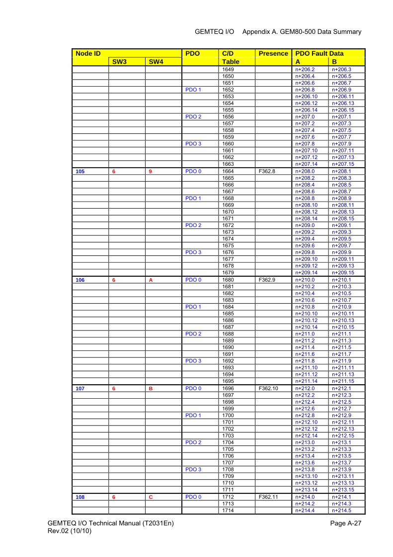
GEMTEQ I/O Appendix A. GEM80-500 Data Summary
Node ID PDO C/D Presence PDO Fault Data SW3 SW4 Table A B 1649 n+206.2 n+206.3 1650 n+206.4 n+206.5 1651 n+206.6 n+206.7 PDO 1 1652 n+206.8 n+206.9 1653 n+206.10 n+206.11 1654 n+206.12 n+206.13 1655 n+206.14 n+206.15 PDO 2 1656 n+207.0 n+207.1 1657 n+207.2 n+207.3 1658 n+207.4 n+207.5 1659 n+207.6 n+207.7 PDO 3 1660 n+207.8 n+207.9 1661 n+207.10 n+207.11 1662 n+207.12 n+207.13 1663 n+207.14 n+207.15 105 6 9 PDO 0 1664 F362.8 n+208.0 n+208.1 1665 n+208.2 n+208.3 1666 n+208.4 n+208.5 1667 n+208.6 n+208.7 PDO 1 1668 n+208.8 n+208.9 1669 n+208.10 n+208.11 1670 n+208.12 n+208.13 1671 n+208.14 n+208.15 PDO 2 1672 n+209.0 n+209.1 1673 n+209.2 n+209.3 1674 n+209.4 n+209.5 1675 n+209.6 n+209.7 PDO 3 1676 n+209.8 n+209.9 1677 n+209.10 n+209.11 1678 n+209.12 n+209.13 1679 n+209.14 n+209.15 106 6 A PDO 0 1680 F362.9 n+210.0 n+210.1 1681 n+210.2 n+210.3 1682 n+210.4 n+210.5 1683 n+210.6 n+210.7 PDO 1 1684 n+210.8 n+210.9 1685 n+210.10 n+210.11 1686 n+210.12 n+210.13 1687 n+210.14 n+210.15 PDO 2 1688 n+211.0 n+211.1 1689 n+211.2 n+211.3 1690 n+211.4 n+211.5 1691 n+211.6 n+211.7 PDO 3 1692 n+211.8 n+211.9 1693 n+211.10 n+211.11 1694 n+211.12 n+211.13 1695 n+211.14 n+211.15 107 6 B PDO 0 1696 F362.10 n+212.0 n+212.1 1697 n+212.2 n+212.3 1698 n+212.4 n+212.5 1699 n+212.6 n+212.7 PDO 1 1700 n+212.8 n+212.9 1701 n+212.10 n+212.11 1702 n+212.12 n+212.13 1703 n+212.14 n+212.15 PDO 2 1704 n+213.0 n+213.1 1705 n+213.2 n+213.3 1706 n+213.4 n+213.5 1707 n+213.6 n+213.7 PDO 3 1708 n+213.8 n+213.9 1709 n+213.10 n+213.11 1710 n+213.12 n+213.13 1711 n+213.14 n+213.15 108 6 C PDO 0 1712 F362.11 n+214.0 n+214.1 1713 n+214.2 n+214.3 1714 n+214.4 n+214.5
GEMTEQ I/O Technical Manual (T2031En) Page A-27Rev.02 (10/10)

GEMTEQ I/O Appendix A. GEM80-500 : Module 1 Data Summary
Node ID PDO C/D Presence PDO Fault Data SW3 SW4 Table A B 1715 n+214.6 n+214.7 PDO 1 1716 n+214.8 n+214.9 1717 n+214.10 n+214.11 1718 n+214.12 n+214.13 1719 n+214.14 n+214.15 PDO 2 1720 n+215.0 n+215.1 1721 n+215.2 n+215.3 1722 n+215.4 n+215.5 1723 n+215.6 n+215.7 PDO 3 1724 n+215.8 n+215.9 1725 n+215.10 n+215.11 1726 n+215.12 n+215.13 1727 n+215.14 n+215.15 109 6 D PDO 0 1728 F362.12 n+216.0 n+216.1 1729 n+216.2 n+216.3 1730 n+216.4 n+216.5 1731 n+216.6 n+216.7 PDO 1 1732 n+216.8 n+216.9 1733 n+216.10 n+216.11 1734 n+216.12 n+216.13 1735 n+216.14 n+216.15 PDO 2 1736 n+217.0 n+217.1 1737 n+217.2 n+217.3 1738 n+217.4 n+217.5 1739 n+217.6 n+217.7 PDO 3 1740 n+217.8 n+217.9 1741 n+217.10 n+217.11 1742 n+217.12 n+217.13 1743 n+217.14 n+217.15 110 6 E PDO 0 1744 F362.13 n+218.0 n+218.1 1745 n+218.2 n+218.3 1746 n+218.4 n+218.5 1747 n+218.6 n+218.7 PDO 1 1748 n+218.8 n+218.9 1749 n+218.10 n+218.11 1750 n+218.12 n+218.13 1751 n+218.14 n+218.15 PDO 2 1752 n+219.0 n+219.1 1753 n+219.2 n+219.3 1754 n+219.4 n+219.5 1755 n+219.6 n+219.7 PDO 3 1756 n+219.8 n+219.9 1757 n+219.10 n+219.11 1758 n+219.12 n+219.13 1759 n+219.14 n+219.15 111 6 F PDO 0 1760 F362.14 n+220.0 n+220.1 1761 n+220.2 n+220.3 1762 n+220.4 n+220.5 1763 n+220.6 n+220.7 PDO 1 1764 n+220.8 n+220.9 1765 n+220.10 n+220.11 1766 n+220.12 n+220.13 1767 n+220.14 n+220.15 PDO 2 1768 n+221.0 n+221.1 1769 n+221.2 n+221.3 1770 n+221.4 n+221.5 1771 n+221.6 n+221.7 PDO 3 1772 n+221.8 n+221.9 1773 n+221.10 n+221.11 1774 n+221.12 n+221.13 1775 n+221.14 n+221.15 112 7 0 PDO 0 1776 F362.15 n+222.0 n+222.1 1777 n+222.2 n+222.3 1778 n+222.4 n+222.5 1779 n+222.6 n+222.7 PDO 1 1780 n+222.8 n+222.9
GEMTEQ I/O Technical Manual (T2031En) Page A-28 Rev.02 (10/10)
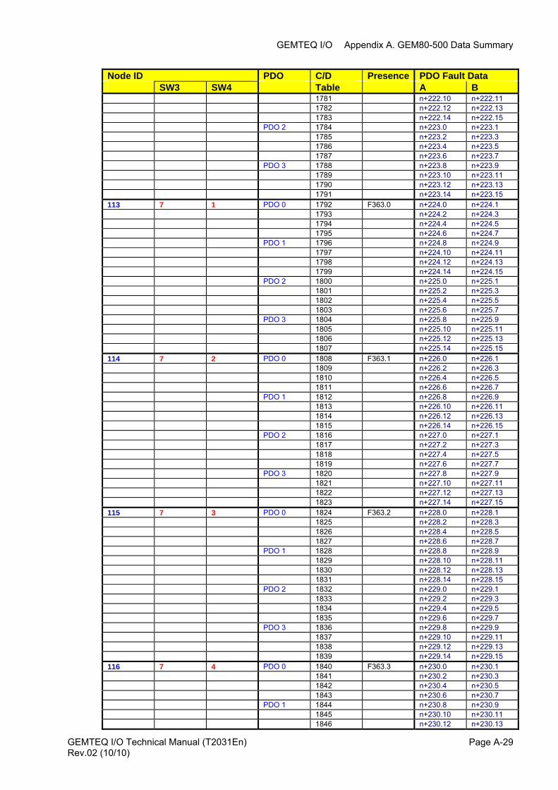
GEMTEQ I/O Appendix A. GEM80-500 Data Summary
Node ID PDO C/D Presence PDO Fault Data SW3 SW4 Table A B 1781 n+222.10 n+222.11 1782 n+222.12 n+222.13 1783 n+222.14 n+222.15 PDO 2 1784 n+223.0 n+223.1 1785 n+223.2 n+223.3 1786 n+223.4 n+223.5 1787 n+223.6 n+223.7 PDO 3 1788 n+223.8 n+223.9 1789 n+223.10 n+223.11 1790 n+223.12 n+223.13 1791 n+223.14 n+223.15 113 7 1 PDO 0 1792 F363.0 n+224.0 n+224.1 1793 n+224.2 n+224.3 1794 n+224.4 n+224.5 1795 n+224.6 n+224.7 PDO 1 1796 n+224.8 n+224.9 1797 n+224.10 n+224.11 1798 n+224.12 n+224.13 1799 n+224.14 n+224.15 PDO 2 1800 n+225.0 n+225.1 1801 n+225.2 n+225.3 1802 n+225.4 n+225.5 1803 n+225.6 n+225.7 PDO 3 1804 n+225.8 n+225.9 1805 n+225.10 n+225.11 1806 n+225.12 n+225.13 1807 n+225.14 n+225.15 114 7 2 PDO 0 1808 F363.1 n+226.0 n+226.1 1809 n+226.2 n+226.3 1810 n+226.4 n+226.5 1811 n+226.6 n+226.7 PDO 1 1812 n+226.8 n+226.9 1813 n+226.10 n+226.11 1814 n+226.12 n+226.13 1815 n+226.14 n+226.15 PDO 2 1816 n+227.0 n+227.1 1817 n+227.2 n+227.3 1818 n+227.4 n+227.5 1819 n+227.6 n+227.7 PDO 3 1820 n+227.8 n+227.9 1821 n+227.10 n+227.11 1822 n+227.12 n+227.13 1823 n+227.14 n+227.15 115 7 3 PDO 0 1824 F363.2 n+228.0 n+228.1 1825 n+228.2 n+228.3 1826 n+228.4 n+228.5 1827 n+228.6 n+228.7 PDO 1 1828 n+228.8 n+228.9 1829 n+228.10 n+228.11 1830 n+228.12 n+228.13 1831 n+228.14 n+228.15 PDO 2 1832 n+229.0 n+229.1 1833 n+229.2 n+229.3 1834 n+229.4 n+229.5 1835 n+229.6 n+229.7 PDO 3 1836 n+229.8 n+229.9 1837 n+229.10 n+229.11 1838 n+229.12 n+229.13 1839 n+229.14 n+229.15 116 7 4 PDO 0 1840 F363.3 n+230.0 n+230.1 1841 n+230.2 n+230.3 1842 n+230.4 n+230.5 1843 n+230.6 n+230.7 PDO 1 1844 n+230.8 n+230.9 1845 n+230.10 n+230.11 1846 n+230.12 n+230.13
GEMTEQ I/O Technical Manual (T2031En) Page A-29Rev.02 (10/10)
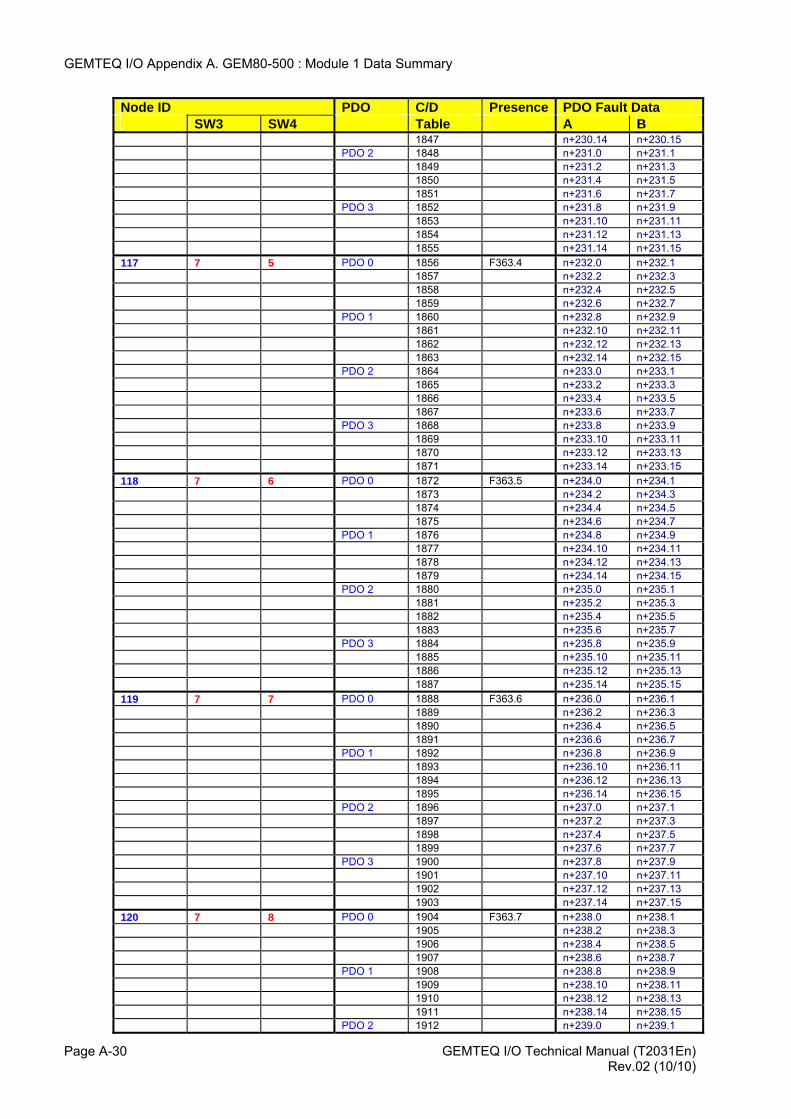
GEMTEQ I/O Appendix A. GEM80-500 : Module 1 Data Summary
Node ID PDO C/D Presence PDO Fault Data SW3 SW4 Table A B 1847 n+230.14 n+230.15 PDO 2 1848 n+231.0 n+231.1 1849 n+231.2 n+231.3 1850 n+231.4 n+231.5 1851 n+231.6 n+231.7 PDO 3 1852 n+231.8 n+231.9 1853 n+231.10 n+231.11 1854 n+231.12 n+231.13 1855 n+231.14 n+231.15 117 7 5 PDO 0 1856 F363.4 n+232.0 n+232.1 1857 n+232.2 n+232.3 1858 n+232.4 n+232.5 1859 n+232.6 n+232.7 PDO 1 1860 n+232.8 n+232.9 1861 n+232.10 n+232.11 1862 n+232.12 n+232.13 1863 n+232.14 n+232.15 PDO 2 1864 n+233.0 n+233.1 1865 n+233.2 n+233.3 1866 n+233.4 n+233.5 1867 n+233.6 n+233.7 PDO 3 1868 n+233.8 n+233.9 1869 n+233.10 n+233.11 1870 n+233.12 n+233.13 1871 n+233.14 n+233.15 118 7 6 PDO 0 1872 F363.5 n+234.0 n+234.1 1873 n+234.2 n+234.3 1874 n+234.4 n+234.5 1875 n+234.6 n+234.7 PDO 1 1876 n+234.8 n+234.9 1877 n+234.10 n+234.11 1878 n+234.12 n+234.13 1879 n+234.14 n+234.15 PDO 2 1880 n+235.0 n+235.1 1881 n+235.2 n+235.3 1882 n+235.4 n+235.5 1883 n+235.6 n+235.7 PDO 3 1884 n+235.8 n+235.9 1885 n+235.10 n+235.11 1886 n+235.12 n+235.13 1887 n+235.14 n+235.15 119 7 7 PDO 0 1888 F363.6 n+236.0 n+236.1 1889 n+236.2 n+236.3 1890 n+236.4 n+236.5 1891 n+236.6 n+236.7 PDO 1 1892 n+236.8 n+236.9 1893 n+236.10 n+236.11 1894 n+236.12 n+236.13 1895 n+236.14 n+236.15 PDO 2 1896 n+237.0 n+237.1 1897 n+237.2 n+237.3 1898 n+237.4 n+237.5 1899 n+237.6 n+237.7 PDO 3 1900 n+237.8 n+237.9 1901 n+237.10 n+237.11 1902 n+237.12 n+237.13 1903 n+237.14 n+237.15 120 7 8 PDO 0 1904 F363.7 n+238.0 n+238.1 1905 n+238.2 n+238.3 1906 n+238.4 n+238.5 1907 n+238.6 n+238.7 PDO 1 1908 n+238.8 n+238.9 1909 n+238.10 n+238.11 1910 n+238.12 n+238.13 1911 n+238.14 n+238.15 PDO 2 1912 n+239.0 n+239.1
GEMTEQ I/O Technical Manual (T2031En) Page A-30 Rev.02 (10/10)
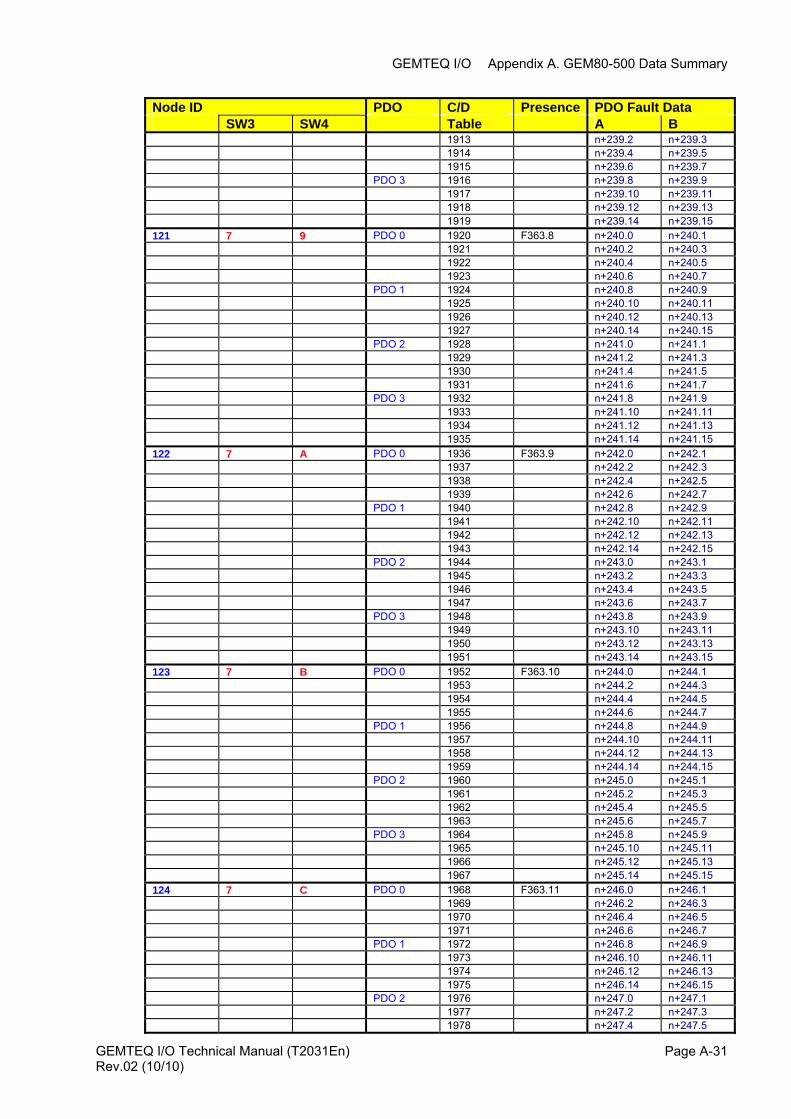
GEMTEQ I/O Appendix A. GEM80-500 Data Summary
GEMTEQ I/O Technical Manual (T2031En) Page A-31
Node ID PDO C/D Presence PDO Fault Data SW3 SW4 Table A B 1913 n+239.2 n+239.3 1914 n+239.4 n+239.5 1915 n+239.6 n+239.7 PDO 3 1916 n+239.8 n+239.9 1917 n+239.10 n+239.11 1918 n+239.12 n+239.13 1919 n+239.14 n+239.15 121 7 9 PDO 0 1920 F363.8 n+240.0 n+240.1 1921 n+240.2 n+240.3 1922 n+240.4 n+240.5 1923 n+240.6 n+240.7 PDO 1 1924 n+240.8 n+240.9 1925 n+240.10 n+240.11 1926 n+240.12 n+240.13 1927 n+240.14 n+240.15 PDO 2 1928 n+241.0 n+241.1 1929 n+241.2 n+241.3 1930 n+241.4 n+241.5 1931 n+241.6 n+241.7 PDO 3 1932 n+241.8 n+241.9 1933 n+241.10 n+241.11 1934 n+241.12 n+241.13 1935 n+241.14 n+241.15 122 7 A PDO 0 1936 F363.9 n+242.0 n+242.1 1937 n+242.2 n+242.3 1938 n+242.4 n+242.5 1939 n+242.6 n+242.7 PDO 1 1940 n+242.8 n+242.9 1941 n+242.10 n+242.11 1942 n+242.12 n+242.13 1943 n+242.14 n+242.15 PDO 2 1944 n+243.0 n+243.1 1945 n+243.2 n+243.3 1946 n+243.4 n+243.5 1947 n+243.6 n+243.7 PDO 3 1948 n+243.8 n+243.9 1949 n+243.10 n+243.11 1950 n+243.12 n+243.13 1951 n+243.14 n+243.15 123 7 B PDO 0 1952 F363.10 n+244.0 n+244.1 1953 n+244.2 n+244.3 1954 n+244.4 n+244.5 1955 n+244.6 n+244.7 PDO 1 1956 n+244.8 n+244.9 1957 n+244.10 n+244.11 1958 n+244.12 n+244.13 1959 n+244.14 n+244.15 PDO 2 1960 n+245.0 n+245.1 1961 n+245.2 n+245.3 1962 n+245.4 n+245.5 1963 n+245.6 n+245.7 PDO 3 1964 n+245.8 n+245.9 1965 n+245.10 n+245.11 1966 n+245.12 n+245.13 1967 n+245.14 n+245.15 124 7 C PDO 0 1968 F363.11 n+246.0 n+246.1 1969 n+246.2 n+246.3 1970 n+246.4 n+246.5 1971 n+246.6 n+246.7 PDO 1 1972 n+246.8 n+246.9 1973 n+246.10 n+246.11 1974 n+246.12 n+246.13 1975 n+246.14 n+246.15 PDO 2 1976 n+247.0 n+247.1 1977 n+247.2 n+247.3 1978 n+247.4 n+247.5
Rev.02 (10/10)
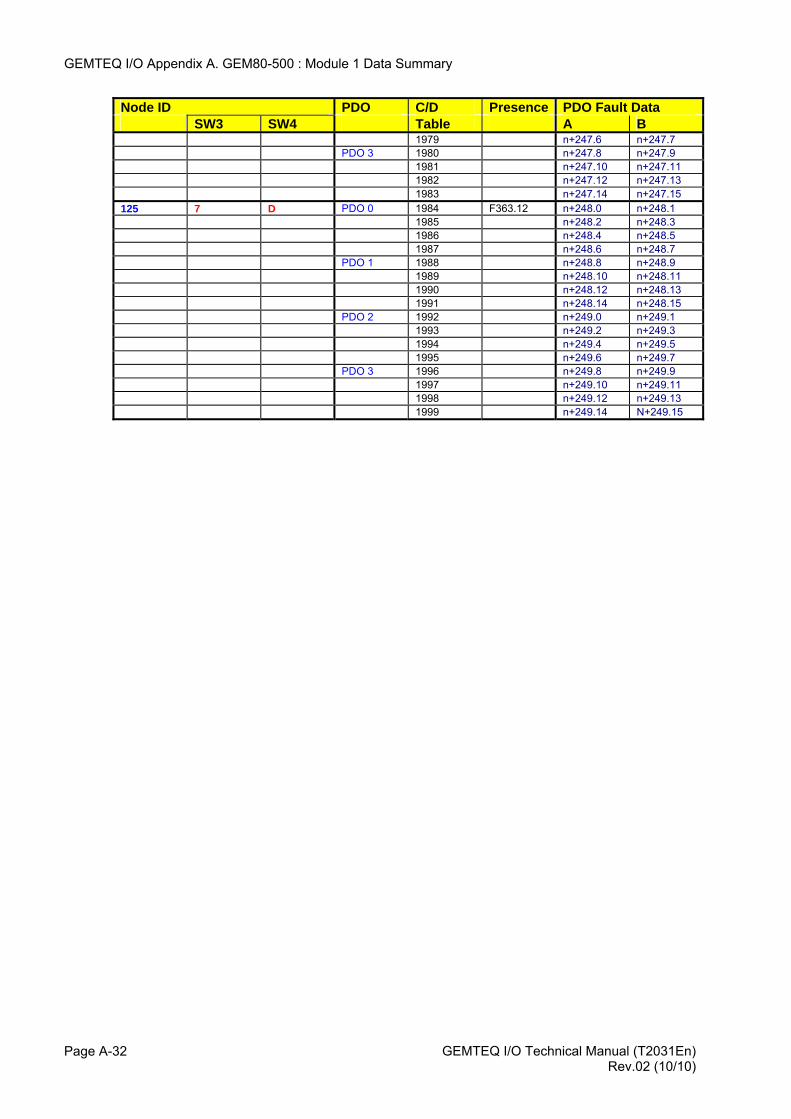
GEMTEQ I/O Appendix A. GEM80-500 : Module 1 Data Summary
GEMTEQ I/O Technical Manual (T2031En) Page A-32
Node ID PDO C/D Presence PDO Fault Data SW3 SW4 Table A B 1979 n+247.6 n+247.7 PDO 3 1980 n+247.8 n+247.9 1981 n+247.10 n+247.11 1982 n+247.12 n+247.13 1983 n+247.14 n+247.15 125 7 D PDO 0 1984 F363.12 n+248.0 n+248.1 1985 n+248.2 n+248.3 1986 n+248.4 n+248.5 1987 n+248.6 n+248.7 PDO 1 1988 n+248.8 n+248.9 1989 n+248.10 n+248.11 1990 n+248.12 n+248.13 1991 n+248.14 n+248.15 PDO 2 1992 n+249.0 n+249.1 1993 n+249.2 n+249.3 1994 n+249.4 n+249.5 1995 n+249.6 n+249.7 PDO 3 1996 n+249.8 n+249.9 1997 n+249.10 n+249.11 1998 n+249.12 n+249.13 1999 n+249.14 N+249.15
Rev.02 (10/10)
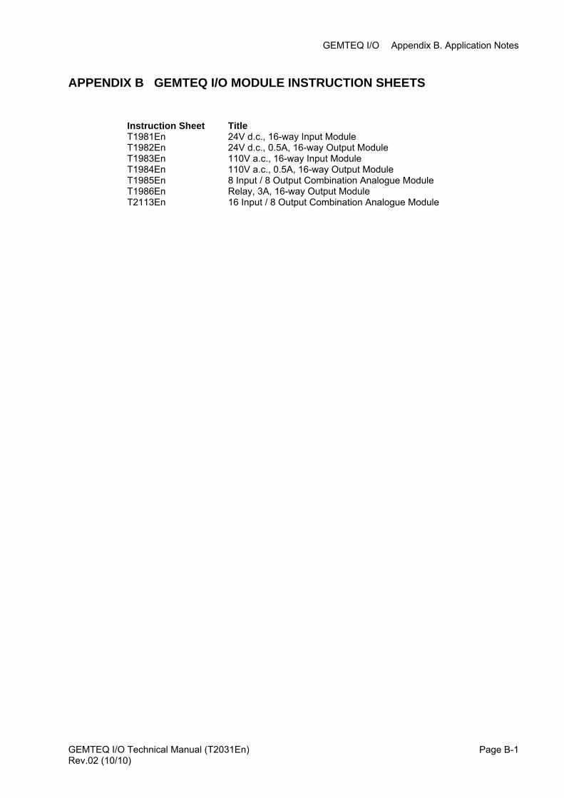
GEMTEQ I/O Appendix B. Application Notes
APPENDIX B GEMTEQ I/O MODULE INSTRUCTION SHEETS
Instruction Sheet Title T1981En 24V d.c., 16-way Input Module T1982En 24V d.c., 0.5A, 16-way Output Module T1983En 110V a.c., 16-way Input Module T1984En 110V a.c., 0.5A, 16-way Output Module T1985En 8 Input / 8 Output Combination Analogue Module T1986En Relay, 3A, 16-way Output Module T2113En 16 Input / 8 Output Combination Analogue Module
GEMTEQ I/O Technical Manual (T2031En) Page B-1Rev.02 (10/10)

GEMTEQ I/O Appendix B. Application Notes
This page intentionally left blank
GEMTEQ I/O Technical Manual (T2031En) Page B-2 Rev.02 (10/10)

GEMTEQ I/O Appendix E. GEMCAN I/O Scanner Firmware Upgrade
APPENDIX C NODE GUARD PERIOD AND MASTER CHANGEOVER TIME
Master Change-over time
In a change over system it is good practice to set the change-over time to at least twice the selected Node Guard Period Time (NGPT).
Consider the following:-
At 250K Baud the default NGPT is 80mS, setting the change-over time in each controller to 100mS may cause the system to momentarily swap to the "off-line" controller should any changes be made to it's operational state e.g. Power Cycle or recompile.
To prevent the above, reduce the Node Guard Period or increase the change-over time as required.
Freeze Fallback
A slave GEMTEQ output module has a default Freeze / Fallback delay time of 500ms.
At the selected Node Guard Period Time (NGPT), the GEMTEQ master sends a node guard message to the first node and the second master (if fitted). The next Node Guard Period Time (NGPT), a node guard message is sent to the second node + the second master (if fitted).
This continues for each node configured (C/D Reference in ladder) before it starts again.
Assume a Node Guard Period Time of 80mS and eight nodes have been configured in the ladder.
Note: The node ID’s do not have to be sequential, the system only sends a node guard to nodes referred to in the ladder program.
Each node is sent a unique Node Guard Message and as such it will take 640mS to service each node.
Number of Nodes (8) x Node Guard Period (80mS) = 640mS
It can be seen that with a default Fallback delay (500mS) the modules will go to the fallback state
To prevent the above, reduce the Node Guard Period or increase the Fallback delay as required.
GEMTEQ I/O Technical Manual (T2031En) Page E-1 Rev.02 (10/10)

GEMTEQ I/O Appendix E. GEMCAN I/O Scanner Firmware Upgrade
GEMTEQ I/O Technical Manual (T2031En) Rev.02 (10/10)
Page E-1
France Converteam SAS 1, Square John H. Patterson 91345 Massy Cedex - France Tel : +33 (0)1 77 31 20 00 Fax : +33 (0)1 60 19 64 95 Germany Converteam GmbH Culemeyerstraße 1, 12277 Berlin - Germany Tel : +49 (0) 30 7622 – 0 Fax : +49 (0) 30 7622 2109 UK Converteam UK Ltd West Avenue, Kidsgrove Stoke-on-Trent, ST7 1TW – UK Tel : +44 (0) 1782 781000 Fax : +44 (0) 1782 781001 USA Converteam Inc. 610 Epsilon Drive Pittsburgh, PA 15238 - USA Tel : +1 412 967 0765 Fax : +1 412 967 7660
© C
onve
rtea
m U
K L
td -
2010
- Pu
blic
atio
n N
o. T
2031
Th
e lo
go C
onve
rteam
and
thei
r fra
mew
orks
are
trad
emar
ks a
nd s
ervi
ce tr
adem
ark
appl
icat
ions
of
Con
verte
am. O
ther
nam
es m
entio
ned,
regi
ster
ed o
r not
, are
the
prop
erty
of t
heir
resp
ectiv
e co
mpa
nies
.