Embed Size (px)
DESCRIPTION
ppt
Citation preview
PRESENTATION ON GENERATOR
PRESENTED By:
Mr. R. S. Bose; Mgr.(EE)

. Working PrincipleThe A.C Generator or alternator is based upon the principle of electromagnetic induction & consists a stationary part called Stator & a rotating part called Rotor. The armature windings are placed in the stator. Field winding is placed in the Rotor & DC supply is given to the field winding. When rotor is rotated, the lines of magnetic flux (viz magnetic field) cut through the stator windings. This induces an electromagnetic force (e.m.f) in the stator windings.
The magnitude of e.m.f (E) = 4.44 f N volts
= Strength of magnetic field in webers
N = Number of turns in a coil of stator winding
f = Frequency in Hz = P n/120
where n = revolutions of rotor
P = Number of poles. For same frequency increase in number of poles decrease the machine speed & vice versa. Hence low speed hydro turbines have 14 to 20 poles & high speed steam turbines have generally 2 poles.

VIEW OF GENERATOR TURBINE ASSEMBLY OF STAGE-I

GENERATOR OF STAGE-I


. Generator Components
1. Stator
2. Stator Windings
3. Rotor
4. Rotor Windings
. Stator Core
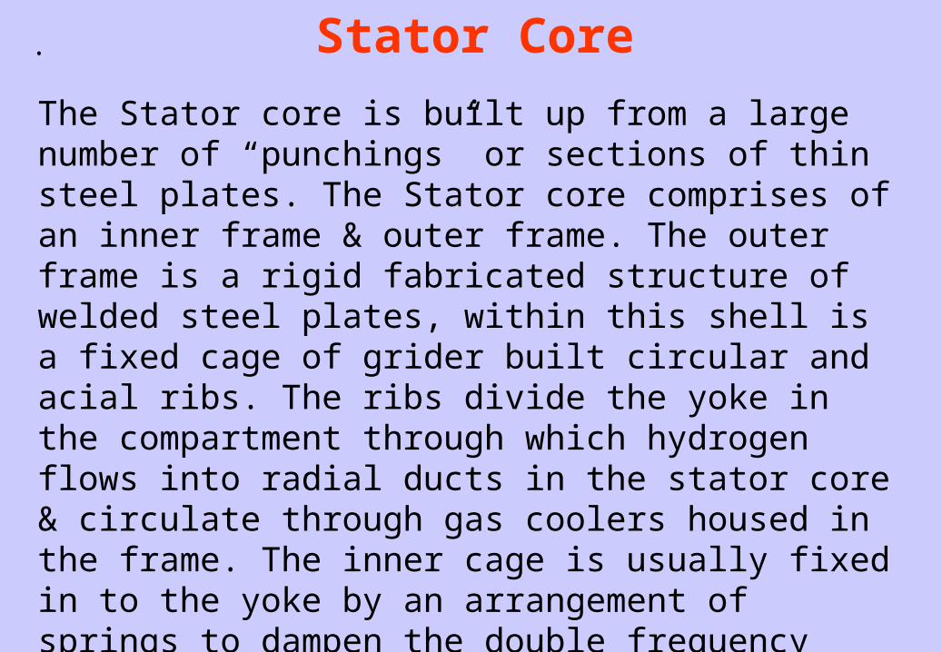
The Stator core is built up from a large number of “punchings” or sections of thin steel plates. The Stator core comprises of an inner frame & outer frame. The outer frame is a rigid fabricated structure of welded steel plates, within this shell is a fixed cage of grider built circular and acial ribs. The ribs divide the yoke in the compartment through which hydrogen flows into radial ducts in the stator core & circulate through gas coolers housed in the frame. The inner cage is usually fixed in to the yoke by an arrangement of springs to dampen the double frequency vibrations inherent in 2 pole generators. RTDs are mounted at the bottom of Stator slots to measure temperature.

.
Stator Windings
Windings for the Stator are made up from copper strips wound with insulated tape which is impregnated with varnish, dried under vacuum & hot pressed to form an solid insulation bar. This bars are then placed in the stator slots and held in with wedges to form the complete winding which is connected together at each end of the core forming the end turns. These end turns are rigidly braced & packed with blocks of insulating material to withstand the heavy forces which might result from a short circuit or other fault conditions.
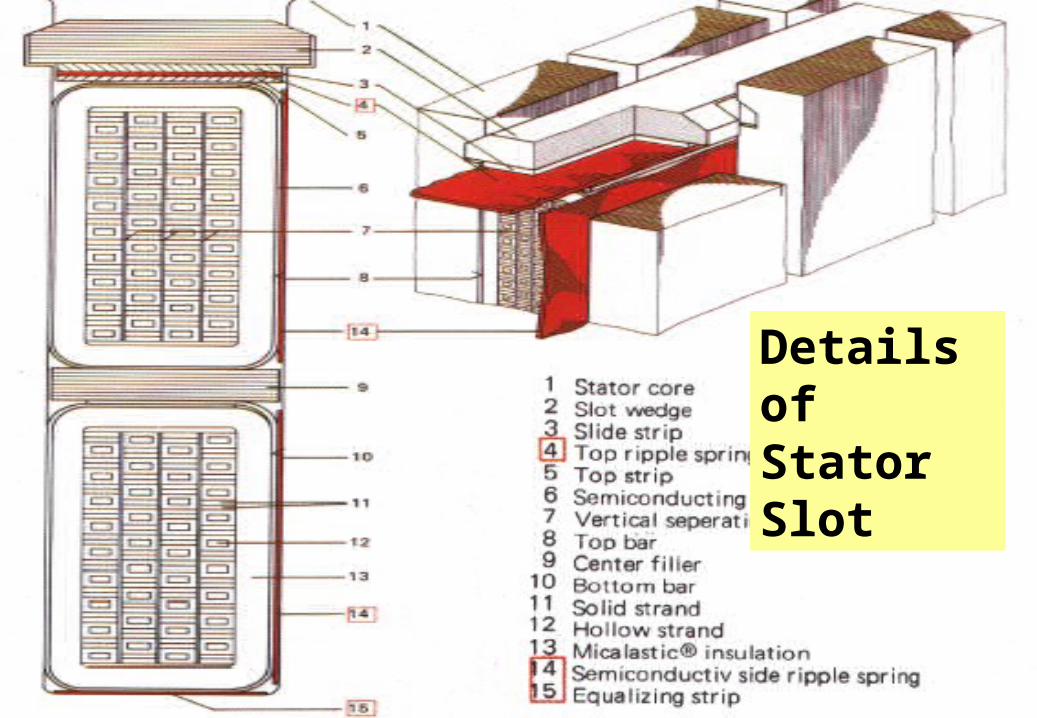
Details of Stator Slot

. Rotor
The Rotor is a cast steel ingot and it is further forged & machined. It should have sufficient dynamic strength to withstand the high speed of the generators.Very often a hole is bored through the centre of the rotor axially from one end to the other for inspection. Slots are then machined for windings & ventilation.
Rotor Windings
Silver bearing copper is used for the winding & mica is used as the insulation between conductors. A mechanically strong insulator like micanite is used for lining the slots.While rotating at high speed centrifugal force tries to lift the windings out of the slots & hence they are contained by wedges.

. Retaining Ring
The centrifugal forces of the rotor end windings are contained by single-piece rotor retaining rings. The retaining rings are made of non-magnetic high-strength steel in order to reduce stray losses.

Rotor Slot Details
1
2
3
4
5
6
8 97

Rotor End Winding
2
5
6
78
1
3
4

Technical Data Sheet of 500 MW Generator

. Comparison of 200MW & 500MW Generator

.
Generator Cooling System
1. Rotor Cooling System
2. Stator Cooling System

. Rotor Cooling System

. Hydrogen Cooling System

Merits & Demerits of H2 CoolingMerits
1. Excellent thermal properties
2. One of the lightest gasses (Low density resulting low windage losses in rotating machine)
3. .Non toxic
4. High diffusion properties giving efficient coolingDemerits1. .Flammable/ Highly explosive when mixed with air/O2
2. Highly sensitive to ignition/sparks/static charges3. Asphixiant in closed spaces4. Auto ignition properties
(Temp 500C, H2: Air / O2 4% - 74% ) under this condition H2 is explosive

Stator Cooling System

The closed loop cooling system consists of the following:-

GENERATOR COOLING WATER CIRCUIT

PRIMARY WATER SYSTEM21
3
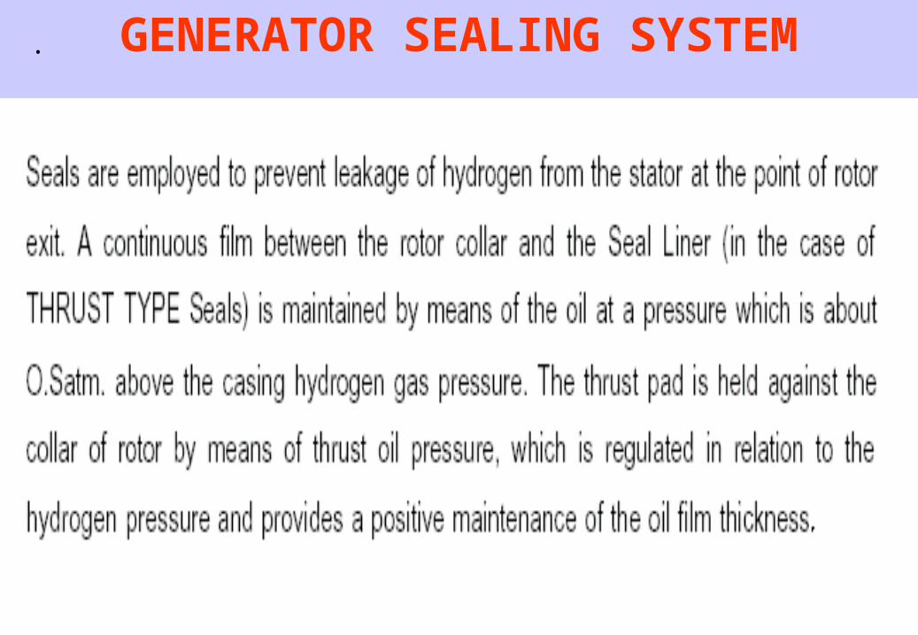
. GENERATOR SEALING SYSTEM
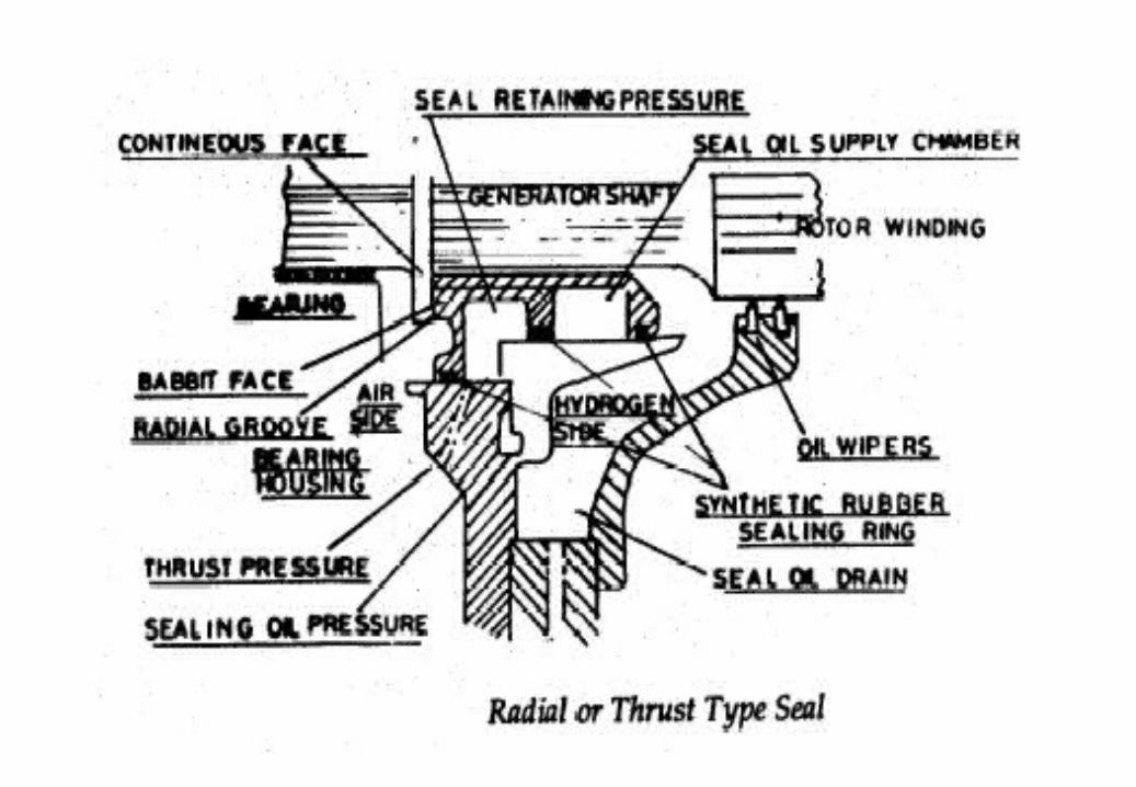
.
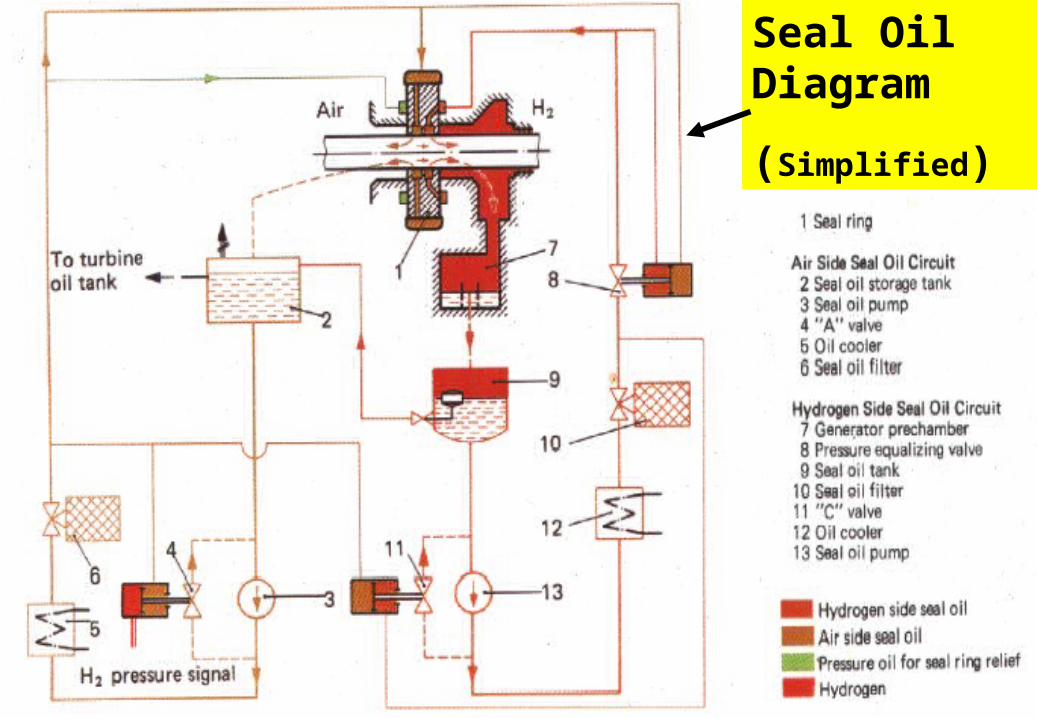
Seal Oil Diagram
(Simplified)

EXCITATION METHODS
1. Brush type system apply the output of a separate DC generator (exciter) to the slip rings of the rotor.
Disadvantage :- Brush gives sparking & may cause fire hazards.
2. Brushless excitation systems utilize an integral exciter and rotating rectifier assembly that eliminates the need for brushes and slip rings. Here we have A.C exciter. AC is converted to D.C by power diodes which are mounted to shaft as bridge rectifier. Output of the rectifier goes to field winding without any slip.

Brush Type Excitation System

Brushless Excitation System

Basic Arrangement of Excitation System
1
8
5
4
3
2
7
6
9
10

Faults for Generator1. Internal faults
a) Stator Faults (Phase to ground, Phase to Phase & Inter turn)
b) Rotor Faults (Winding to Earth, Interturn)
2. Abnormal operating conditions
a) Loss of Excitation
b) Overload
c) Overvoltage
d) Under freq / Over freq
e) Unbalance Current
f) Motoring
g) Loss of synchronism
h) Sub synchronous oscillations
3. Mechanical Faults or Conditions
a) Over speed b) Failure of Prime Mover c) Loss of Vacuum
4. External Faults
a) Faults in Lines & busbars
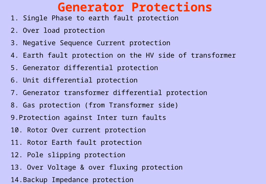
Generator Protections1. Single Phase to earth fault protection
2. Over load protection
3. Negative Sequence Current protection
4. Earth fault protection on the HV side of transformer
5. Generator differential protection
6. Unit differential protection
7. Generator transformer differential protection
8. Gas protection (from Transformer side)
9.Protection against Inter turn faults
10. Rotor Over current protection
11. Rotor Earth fault protection
12. Pole slipping protection
13. Over Voltage & over fluxing protection
14.Backup Impedance protection

Generator Synchronization
Generator is synchronized with the grid when following conditions are satisfied:-
1. Voltage should be same (Changed by changing excitation)
2. Frequency should match (Changed by changing steam input)
3. Phase sequence should match
4. Phase difference should be zero
(For Synchronization there is both manual & auto mode. For Auto mode ATRS system is there. In manual mode the closing impulse to Generator breaker is given when the synchroscope pointer is between 11 to 12 Clock position).)


THANK YOU