Embed Size (px)
Citation preview
,. ' 3 @,
,
UNITED E: CINEERS & CONSTRUCTGRS I"C..
QUALITY CONTROL PROCEDURE QC-1, REV. 9
FOR
GENERAL CONSTRUCTIO:{ AND STRUCTURAL CONCRETE
May 10, 1973.
.
TilREE MILE ISLAND - PROJECT NO. I
METROPOLITAN EDISON CO GAhT
.
.
M '' U*
Approved by: / '
B. G. Avers,Manager of Quality Assurance
Rev. 9: Insert Revision, Page 14 General Pu'olic Utilities
1566 138
5067911000 M
.- .--. .- - - - ~ . .
.
',- ,
s t
.
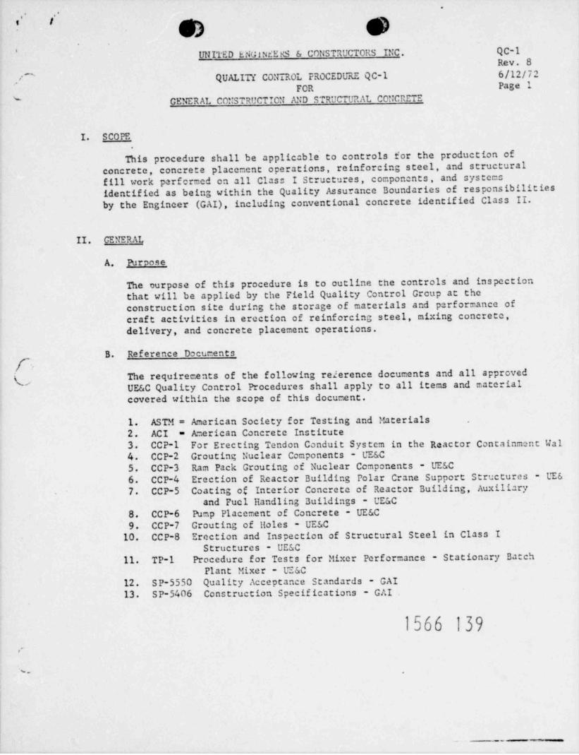
UNITED ENGINEE KS & CONSTRUCTORS INC. QC-1'
Rev. 8QUALITY CONTROL PROCEDURE QC-1 6/12/72''''
FOR Page 1
CENERAL CONSTRUCTION AND STRUCTURAL CONCRETE
I. SCOPE.
This procedure shall be applicable to controls tor the production ofconcrete, concrete placement operations, reinforcing steel, and structuralfill work parfcrmed on all Class I Structures , components , and systemsidentified as being within the Quality Assurance Boundaries of responsibilitiesby the Engineer (GAI), including conventional concrete identified Class II.
II. GENERAL
A. Purpose
The ourpose of this procedure is to outline the controls and inspectionthat will be applied by the Field Quality Control Group at theconstruction site during the storage of materials and performance ofcraft activities in erection of reinforcing steel, mixing concrete,
delivery, and concrete placement operations.
B. Reference Documents,_
(, The requirements of the following reierence documents and all approvedUE&C Quality Control Procedures shall apply to all items and materialcovered within the scope of this document.
1. ASTM = American Society for Testing and Futerials2. ACI = American Concrete Institute3. CCP-1 For Erecting Tendon Conduit System in the Reactor Containment Wal4. CC P-2 Grouting Nuclear Components - UE&C5. CCP-3 Ram Pack Grouting of Nuclear Components - UE&C6. CCP-4 Erection of Reactor Building Polar Crane Support Structures - UE67. CCP-5 Coating of Interior Concrete of Reactor Building, Auxiliary
and Fuc1 Handling Buildings - UE&C
8. CCP-6 Pump Placement of Concrete - UE&C9. CCP-7 Grouting of Holes - UE&C
10. CCP-8 Erection and Inspection of Structural Steel in Class IStructures - UESC
11. TP-1 Procedure for Tests for Mixer Performance - Stationary BatchPlant Mixer - UE&C
12. SP-5550 Quality Acceptance Standards - GAI13. SP-5406 Construction Specifications - GAI
1566 139<
%e
.
.- .'
.
QC-1Rev. 8
-
6/12/72'Page 2s.
III. RESPONSIBILITY
A. The UE&C Field Quality Control Group are responsible for implementing ,the requirements specified herein and references to Quality ControlInspectors in this procedure include UE&C Quality Control Inspectorsand the Independent Testing Agency Inspectors.
B. Independent Testing Acency
1. United Engineers & Constructors will retain the services of anindependent testing agency (T.L.) to perform the necessary inspectionsand tests required within the scope of these procedures.
2. The activities of the T.L. will be under the direction of the UE&CField Supervisor - Quality Control relative to their scope andduties at the project site.
3. The T.L. shall have sufficient personnel and equipment availableat the project site in order to carry out the duties assigned ordirected by the Field Supervisor - Quality Control.
(NOTE: Any work performed by the T.L. off site for UESC will be-s
as authorized by the Field Supervisor - Quality Control.)
s..
4. Reports and records generated by the T.L. will be' submitted to theField Supervisor - Quality Control and will become a part of thequality control file as required. Copies of the reports will bedistributed to the Engineer and the Owner as required.
IV. BATCH PLANT INSPECTION
A. Batch Plant Oncration.
*
The Quality Control Inspector at the Batch Plant shall inspect theoperation for compliance with the following requirements:
1. When concrete is produced from a site located central mix ortransit mix operation:
a. Inspect the concrete batch plant, including aggregate storageareas, weighing and measuring systems, stationary mixers, andmixer trucks to conform to ASTM C94-65.
b. Prior to start of operation of the stationary mixer, mixerperformance tests as required by ACI 301, Section 701 will bcperformed by the Quality Control Inspector in accordance with,
UE&C Test Procedure No. TP-1.ss
1566 140
_ . -- .-

t i
O.r.
QC-1Rev. B
6/12/72-
Page 3'-
'~IV. BATCH PL\NT INSPECTION (Continued)
c. Check to assure that aggregate and cement used in batchingconcrete for the scheduled pour are approved and comply with
'
requirements noted in Appendix A.
d. Prior to the first batch, sample and test the fine and coarseaggregate for gradation ani moisture content in accordancewith ASTM C566. Fine and coarse aggregate will be checkedfor moisture content at least every two(2) hours during *production and corresponding water adjustments made as needed g''N,/
,
4 thenwrmy L"5ft'(dy e. De scales shall be calibrated prior to use.# S tandard weights~
will be availabic for periodic checking of scale calibration,however, calibration shall be scheduled in accordance with
QC-13.
2. Water measurement and admix dispensing will be checked by measuringthe amount of liquid delivered from a dial setting. Watermeasurement will be checked weekly and admix dispensing will bechecked continuously by the use of site gauges (or clear containers)through which the liquids flow. -
[~ 3. The autonatic moisture probe will be checked prior to dailyoperation of the plant against known sand moisture content and,"corrections to water settings made in accordance with ParagraphIV.B.lb.(1) as applicable.
4. Check batch card to see that proper approved mix is being, batchedand that card is punched correctly.
5. Check the mixing cycle setting and actual time of each cycle duringcentral mix operations to assure it does not exceed the tolerancerange from a minimum of 75 seconds to e' maximum of 135 seconds.We mix timing device shall be checked for calibration as requiredby the manufacturer and the Batch Plant Inspector will periodicallycheck the time cycle with a stop watch.
6. Check that each truck drum is free of excess water before mixingredients are introduced into it. This shall be the responsibilityof the batch plant supervisor and subject to audit by the batchplant inspector.
7. Make daily checks of Batch Plant conveyors to assure that mixingredients arc introduced into the stationary mixer or transitmixer simultaneously.
1566 141
_
.-- ,_.
..-..y-. - __
- ,i
. .-s t }_
.
QC-1g Rev. 8.~
' g0/ 6/12/72Uf j Page 4s_
IV. BATCH PLANT INSPECTION (Continued)
8. The Batch Plant Inspector shall check the batch cord to assurethat proper mix is being batched, that the card is correctlypunched, and:
a. Prepare batch tickets that will show: date, time loaded,truck number, load number, initial number of revolutions oncounter, concrete design strength, amount of concrete loaded,amount of each ingredient, including ice added, percent surfacemoisture of fine aggregate and coarse aggregate. total watercontent per yard (including surface moisture of aggregates),amount of water allowable to be added at the pour site, portionof the structure where used, mixing time (cycle) and signatureof the batch plant inspector.
b. Check recording tapes for confirmation of actual batch weightsand attach copy to the batch ticket (any notations made on therecording tape shall be initialed by the Batch Plant Inspector).
c. The Quality Control Inspector at the pour site shall completethe Batch Ticket in accordance with the requirements forgconcrete placement.
,
(9. During Central Mix Operations check the slump, air content, and
the temperature of the first two(2) truckloads of concrete batchedeach day to verify that concrete meets the specified tolerances.If slump, air content, or temperature is out of tolerance the loadshall be rejected. Subsequent truckloads shall be checked untiltest results of two(2) consecutive truckloads meet specified tolerances.The Batch Plant Inspector shall note on the Batch Ticket the reasonfor rejection and where the rejected concrete will be used.
'
10. Concrete produced by Transit Mix operations shall be checked at thepour site during field tests of concrete placement.
B. Water Adiustment (Batch Plant)
1. The Quality Control Batch Plant Inspector shall be solely responsiblefor making adjustments in water content of the mix at the batchplant. Recommendations for adjustments of water content shall bemade by the Quality Control Field Inspector (s), UE&C Quality Controlpersonnel, UELC Construction Supervision, or Da ch Plant Operators.However, only the Quality Control Batch Plant Inspector shall beauthorized to adjust water content when specified herein.
, a. Adjustment to the water content shall not exceed the water-cement ratio for the approved design min as noted in Appendix A.
..
1566 142
.
, _ mm +e esee **'w ,, _ -- - - -
'
. ,
r y. . QC-1nn -D D ia .
q p Rev. 8<-.
-
b . . ( "
23 6/12/72'V " J
Page 5"
IV. BATCll PLANT INSPECTION (Continued)
b. When applicable, water adjustments shall be made as follows:
(1) Adjust the automatic water setting to account for surfacemoisture of fine aggregate to assure the correct additionof water as called for in the mix design. The "over-under"moisture gauge will be monitored and if the indicationsare that the fine aggregate is running wetter or drierthan the determined setting, the surface moisture will berechecked and the water setting adjusted accordingly.
(2) Enough water will be added at the batch plant to producean estimated 3" slump. In addition, water may be addedat the pour site if necessary, under the direction of theQuality Control Inspector and.in accordance with theprovisions of these procedures and those of SP-5406.
The Batch Plant Inspector shall show on the batch ticket howc.much water can be added to the load without execeding theallowabic maximum water-ccment ratio.
,,
,
\V. FIELD INSPECTION (PREPLACEMENT)
A. Found a tion
1. Vapor barriers shall be used under slabs poured on earth subgradein the areas indicated on the Engineer's drawings.
2. No concrete may be placed on frozen subgrade material.
3. On top of rock, and as directed by GAI, a concrete scal mat (3"minimum) shall be placed below the bottom of structural concrete.Elevation shall be mapped and/or approved by CAI and verified byUE&C Quality Control.
4. Rock subgrs , shall be cicaned, washed, and airblown prior toplacing structural concrete. Old concrete surfaces shall be cleanedby water jet, brushing or air-blowing prior to placement of a newpour.
B. Structural Fill
1. Prior to placing structural concretc on compacted fill, the fill willhave been checked by the Quality Control Inspector to determine thacpercentage compactien or relative density has been achieved. Till
dens ity may be determined by the Sand Cane Me thod (AST'i D- 155e),' nalloon Method (AS'I?! D-2167) or AAS110 - Field ' Determination o f Ikusi ty
In-Place (T 147-54) and shall be compacted to a minimum of 70:: relativedennity.
1566 143. .
,..
.
-
QC-1.
Rev. 86/12/72''
'
7 Page 6s
V. FTELD IMSPECTION /PREpLACE32ST) (Continued)
2. Subgrade will be free from debris and organic material and shallbe thoroughly wetted unicss a vapor barrier is installed.
3. Fill material from bcrrow areas previously selected by the Engineersshall be sampled by the Quality Control Inspector for determinationof moisture-density relationships.
Selected non-plastic fill material shall conf orm to compactiona.standard ASTM D2049 and acceptance standard shall be 707.*
minimum relative density,
b. Selected plastic fill shall comply with compaction standardAASHO modified method and acceptance standard shall be 95% ofmaximum density, minimum and t 2% of optimum moisture at timeof co=paction.
Prior to beginning placing fill on any day, the surf ace of thec.existing material will be scarified to a depth of at least6 inches and moisture conditioned to within 2% of optimummoisture. -
/ d. Fill caterial placed below and adjacent to concrete foundations,.
(_ will be ce=pacted in 8" layers. Fill materials placed intrenches for items such as pipe lines, conduit, and ducts uillbe compacted in 12" layers.
C. Forms and Reinforcing Steel ,
1. Prior to a pour, construction will check that f orms are clean,oiled, secure, and reasonably tight with e=bcdments located per drawing.
2. Size, placement, splicing, or cadwelding of reinforcing stealwill be checked as required by the specifications and applicabledrawings. -
3. It shall be the responsibility of construction to assure that onlyapproved reinforcing steel (subject to audit by the Quality ControlGroup) is used and that Cadueld operators are qualified to complywith Appendix B. Completed'cadweld splices shall be inspected byQuality Centrol and sampics shall be sc1ceted to be tested inaccordance with the acceptance criteria in Appendix B.
1566~144
. . .
~--
-. __ ,_ _ , _ _ . _ . _ _ , _ay
.-,
O D' '
' '
QC-1Rev. 8
''' 6/12/72Page 7
V. FIELD INSPECTION (PPIPIACEMENT) (Continued)
4. Checking of forms, embedments, and reinforcing steel including ,
Cadwelds, as noted above, shall be documented on the Concrete
Placement Checkout Sheet (Reference Attachment A). The Quality
Control Inspector shall verify the condition of pour base; fo rms ;and location, size and quantity of rebar; tying and splicing ofreinforcing steel and concur t:ith other quality Control Engineers;i.e. , Electrical, Mechanical, Welding, etc. , prior to placing concreteand indicate his acceptance on the Inspectors Concrete CheckoutSheet and Concrete Status Report (Refence Attachment B & C).
5. Results of all inspections shall be documented and reported to theUE&C Field Supervisor - Quality Control.
VI. CONCPITE PLACE >ENT INSPECTION
A. Delivered Concrete
1. Concrete shall not be ordered for placement until the ConcretePlacement Check-Out Sheet is completed by construction andsigned-off by Quality Control after completion of final preplacement
f-inspcerinn.'
~.
2. The UE&C Concrete Supervisor and Quality Control Personnel shallhave the authority to reject truckloads of concrete. Dispositionand intended use of rejected concrete shall be documented on theBatch Plant Ticket by the Quality Control Inspector.
3. The Quality Control Inspector shall make the following checks onconcrete delivered for placement.
a. Obtain Batch ticket from the driver and note the initialrevolution counter reading and prepare for sample from themiddle 80*/. of the load.
(1) Upon arrival, check each truck drum revolution counterand record on the Batch Ticket the number of revolutionsat agitating speed or mixing speed and the final revolutioncount at completion of dischargc.
(2) Central Mix loads that have had more than 300 totalrevolutions or that have not been placed 1 1/2 hours altermixing shall be rejected.
1566 145. . .
-' *'a96 W g P*** h9 *W _ _ _ , , , , _ _ . , , , ,9
...
I
QC-1* *
D**D ]f,(2h;(W@;;D ~3~Y Rev. 8_
ed 6/12/72'
.- es esPage 8
,'
VI. CONCRETE PLACEIT!T INSPECTION (Continued)
(3) Transit (Truck) Mix loads that have had more than 100revolutions at mixing speed, more than 300 totalrevolutions, or that have not been placed 1 1/2 hours*
after mixing shall be rejected.
b. When visual observation indicates that the slump exceedstolerance limits, further discharge of concrete shall bestopped and a slump test will be made immediately. Concretethat is determined out of tolerance shall be rejected.
However, if the test determines that the concrete slump iswithin tolerance, the concretc will be discharged and testedas requi;nd.
c. De terstre .the temperature of the concrete in each truckbefore it is placed and record the temperature on the EatchTicket. Temperature of concrete shall comply with thefollowing requirements:
(Fhan Daily Temp.Type Load Min. Temo. 40 F or Less) Concrete Max. Te nn .
/ Mass Pour 50 F 70 Fi. Others 50 F 90 F
d. When concrete is produced by the Transit Mix Operation(dry-batch - truck mix), at least the first two loads producedeach day thell be checked prior to being discharged. They will bechecked for air content, sluno, and temperature. If the aircontent, slump, or temperature in out of tolerance the loadwill be rejected and the batch plant notified so that thenecessary batching adjustments may be made.
e. Check the concrete in each truck for slump in accordance withASTM C43-66 and record the results on the batch ticket. The.
slump f or 1500 and 3000 poi concrete shall not exceed a rangeof 1 inch to 4 inches. The slump for 5000 pei concrete andall concrete produced for the Reactor Building shall not exceeda range of 1 inch to 3 1/2 inches.
f. If the sluup is found to exceed the maximum limit, the truckmay be allowed to meve aside and turn at agitating speed fornot more than 10 minutes providing time and total revolutionlimits are not exceeded. At the end of this t ime , the slump
will be rechecked and if it is within tolerance limits alladditional tests shall be satisf actorily completed prior toacceptance of the load.
.
1566 146
.
- .. __ _ .- . , . . . . , - - - - - - --. ---
'
QC-1Rev. S. , ,
e' 6/12/72''
VI. CONCRETE PT. ACE"ENT IMSPECTION (Continued) ,
g. Check air content in accordance with ASTM C231 or C173 forevery 50 cu. yds. of concrete placed (or whenever test cylindersare made) by cither the pressure method or the volumetricmethod and record results on the Batch Ticket. Compare testdata with permissible air content tolcrances in Appendix A.
B. Water Ad iuntment (Fieldi
1. Prior to any addition of water at the pour site, the QualityControl Inspector shall check the batch ticket to determine howmuch water may be added without c::ceeding the total water requirement.
2. No water shall be added at the pour site if the temperature andelapsed time after the start of mixing exceeds the followingrequirements:
Max. Elapsed Time Prior toAmbient Temnerarure Addition of Water at Pour Site
Over 90 F 30 minutes75 to 900F 45 minutes,_
0Less than 75 F 1 Hour'
~.
3. In no case shall the following truck revolutions be exceededprior to the addition of water at the pour site.
Transit Mix - 90 Revolutions at Mix Speed .
Central Mix - 100 Revolutions at Agitation Speed
4. The truck drum shall be turned a minimum of 30 revolutions atmix speed after the addition of water at the pour site.
5. The number of drum revolutions for Transit Mix operations shallnot execed 100 revolutions at mixing speed or 300 total revolutionsfor either Transit BEx or Central Mix operations.
6. Water may be added only once to a truck provided the aboverequirements are complied with,
7. Temperature of concrete will also be checked in addition toslump, air, etc. , af ter addition of water at the pour site.
1566 147-
.
- - ~ ~ - - ~ n,_ _ - _ . . .- em w _ .
_- ==- 2
' '
hQC-1Rev. S6/12/72,,
Page 11VI. CONCRETE PTACE"ENT INSPECTION (Continued)
2. An additional set of 2 cylinders shall be made for concrete tobe used in the exterior shell of the Containment Building.
3. Concrete cylinder molds shall conform to the requirements ofASTM C470-65T and certificates of compliance to this specificationwill be available and part of the permanent quality control file.
4. When concrete is being conveyed or placed by pump, supplementarytest sampics shall be taken from the discharge pipe end to determineslump, air content, and temperature. (Reference CCP-6.)
5. From each load of concrete sampled for the make-up of concretecylinders record results of a slump test, temperature check andan air content test per ASTM C231-62.
6. Return field-cured test cylinders from previous pour to fieldlaboratory for curing.
F. Evaluation of Concrete Comnrossion Tests
1. Results of concrete cylinder compression tests shall be evaluatedin accordance with ACI 301, Chapter 17, Paragraph 1703 for 5000'.
' psi concrete and Paragraph 1702 for all other structural concrete._
2. Standard deviations, coefficients of variation, and with-in-testcoefficients of variation may be calculated in accordance withACI 214-65. Calculations of these values is not a specificationrequirement; however, such data will be periodically accumulatedto provide a further means of verifying concrete operation andtesting efficiencies.
3. When concrete test results indicate a design mix is out of controland does not meet requirements specified herein, the GAI structuralengineer shall be immediately informed and corrective actions as hemay direct shall be undertaken.
G. _Curine of Placed Concrete
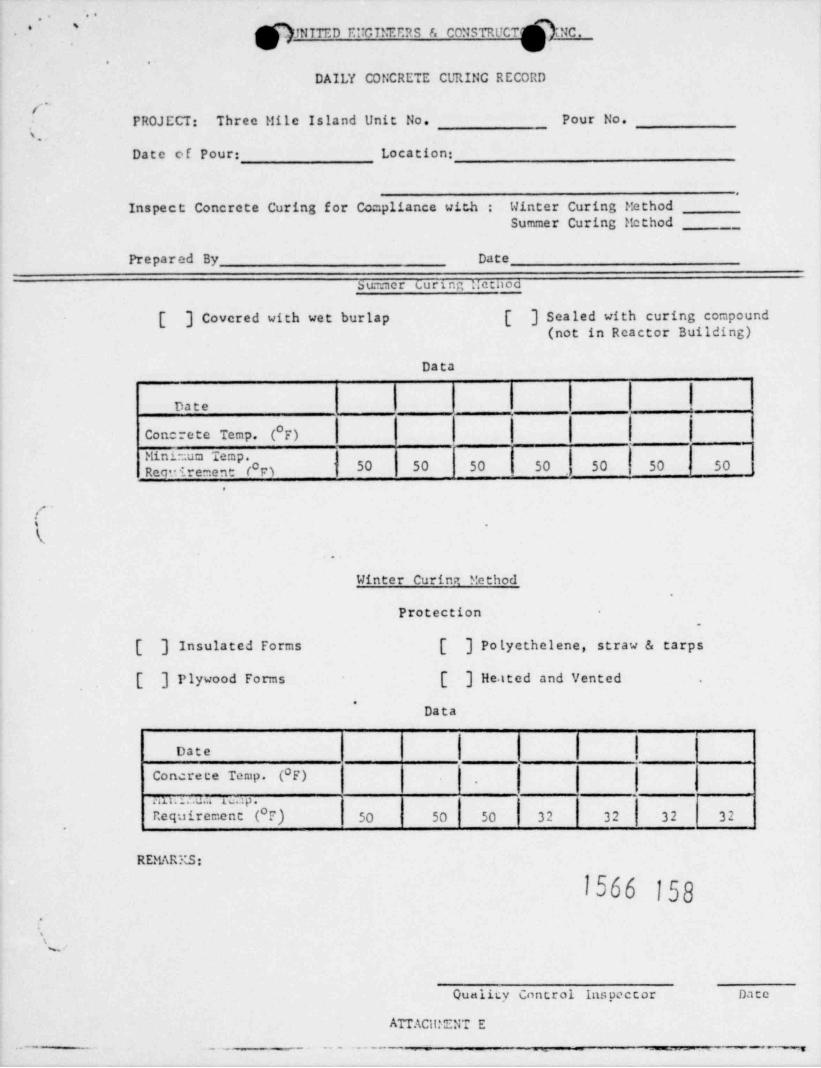
1. Quality Control shall perform daily inspection to assure compliancewith specifications for curing and document inspections of concretecuring activities on the Daily Concrete Curing Record (Attachment E).
2. Concrete curing relative to form removal, curing compounds, wetting,temperature centrol, etc. , shall be as specified in SP-5406,Section 1:15 and SP-5550, paragraph 2.6.
1566 148
N===-~~- --_
___
_ , __, __ g
.
D "" """"
D'
"D- Qc-1*
Rev. 8es eu eu d . - "' 6/12/72_
- Page 10'
VI. C0" CRETE PIACCMENT I"SPECTTON (Continued)
8. Limits as shown in the approved design mix relative to maximumslump, water, and water-ccment ratio shall not be exceeded.Mixing / agitating time and temperature shall not be violated dueto addition of water at the pour site. Such violations are causefor rejection of concrete.
C. Pumned Concrete
1. When concrete is conveyed or placed by pump the pumped concreteactivitics shall comply with requirements of reference documentCCP-6. The concrete shall be sampled and tested at the pump hopperin accordance with requirements specified herein and air content ofdelivered concrete should be 0.57, higher than the specified minimum.In addition, supplementary samples for air, slump, temperature andtest cylinders shall be taken at the discharge pipe end. Supplementarytest samples shall be collected for every 500 cu. yds. placed oronce a ueek for each class of concrete at lesser quantities.
D. Concrete Placement
1. Check concrete placing operations for homoge6 city of mass, assure
'.that the free fall is a maximum of threc(3) feet on finished concretcand five(5) feet on unfinished areas. Houover. if in this particularcase segregation starts occuring, the amount of free fall shall be%decreased. Also check that concrete is properly vibrated, consolidated,and finished as specified on drauings using appropriate equipment.When applicable, provisions for adverse weather conditions shall bemade as specified in SP-5406 paragraph 1:13.3 (Reference ACI 306-66and ACI 605-59) except that accelerators such as Calcium Chlorideand Anti-Freeze compounds shall not be used. The Field Supervisor -Quality Control shall be notified immediately of all discrepantconditions and concrete placement shall be halted until all discrepantconditions have been corrected.
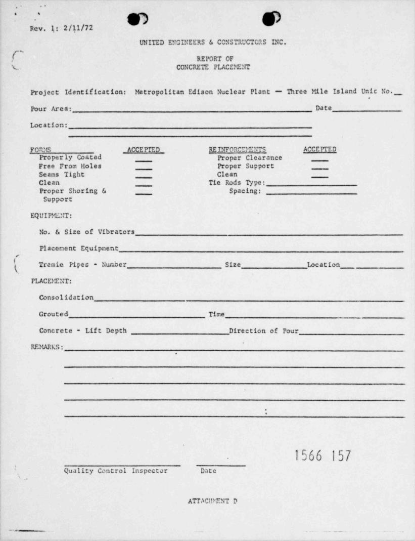
2. Quality Control shall inspect all concrete place =ent activities anddocument inspections on Report of Concrete Placement form. (ReferenceAttachment D. )
E. Test Cvlinders
1. Make and cure one set of concrete test cylinders (6"x12") per ASTMC31-66 daily for each 50 cubic yards of concrete or portion thereofplaced per class. The batch ticket shall indicate the total yardageof that class batched to that time of the day so that field inspectorswill know when sylinders are to be made. When cylinders are made thefield inspector will notify the batch plant inspector so that a crosscheck is a~vailable that the proper number of cylinders sets have beenmade. A set of cylinders shall consist of 6 cylinders for 3000 psiconcrete or for 5000 psi concrete, taken frem the middle 801 of one truckload of concrete. Test cylinders shall be stored in an insulated box
the pour site for 24 hours for field curing and cured initially inataccordance with ASIM C31-66, Section 9(a).
T566 149- . - . . . -- .- .- .- .__ - .- . . -
'
: 9 9.
QC-1.
Rev. 86/12/72
< - Page 12f VII. PERIODIC SAMPLING AMD PRODUCTION TESTINGs.
A. Cement
1. The Quality Control Inspector will sample cement from eachmanufacturer when a new silo is used. These samples will betested for physical and chemical properties in accordance withASTM C150-66. Cement not conforming to the acceptance standardsof ASE1 C150-66 and Appendix A shall not be accepted and theNon-conformance shall be documented.
2. Tests may also be conducted at the cement manufacturing plant.
B. Concrete Ac9recates
1. ' Aggregates delivered to the site will be sampled by QualityControl at least once for every 250 tons received. The samplewill be tested for gradation and determination of finenessmodulus, specific gravity, and absorption.
2. These tests shall be conducted in the field laboratory per testmethods and acceptance standards as noted in Appendix A.
3. Records will be maintained indicating date of receipt, amount( received, gradation test results, and disposition of rejected
loads of material.(4. The mixing water (including ice) shall be checked weekly to assure
it is potable and that it does not contain more than 100 ppm eachof chlorides, sulfides, and nitrates and that its turbidity doesnot exceed 2000 ppm.
C. Concreto Cylinders
1. After sufficient field-curing (usually 24 hours) the cylindersmade by the Quality Control Field Inspector will be transportedto the field labor'atory for stripping and curing and capping inaccordance with ASIM C192-66.
2. Two cylinders from each set will be tested at age 7 days, 2 atage 28 days, and 2 at age 90 days.
3. Two additional cylinders for concrete placed in the exterior ofthe Containment Building will be tested at age 56 days. Compressiontests of cylinders will be evaluated in accordance with Chapter 17of ACI 301-66.
1566 150, . .\x.
__. _ _ .
..,
))- -,
QC-1' '
Rev. 86/12/72Page 13(
[ VII. PERIODIC SMtPLTNG M D PRODUCTION TESTING (Continued)\_
D. Cadweld Solices
1. Cadweld Splices will be tested in tension in accordance withprocedures outlined and referenced in ASTM A615 (minimum ultimatestrength for specimens of Grade 40 - 70,000 psi and Grade 60 -90,000 psi) and shall comply with acceptance criteria noted in App. B.
VIII. REPORTS AND RT. CORDS
A. Quality Control Inspection Reports
1. The following records and reports shall be completed and signedfollowing preparations and inspection of concrete operations:
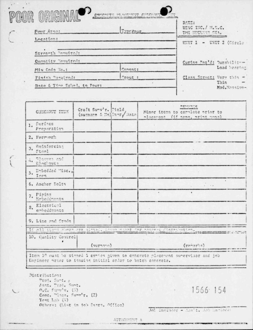
a. Concrete Placement Checkout Sheet (Attachment A)
This form is initiated by Construction activities and signed-of fby Quality Control on checkout item #10 following acceptablepre placement inspection.
Concrete shall not be ordered prior to acceptance and sign-off(' of this form by Quality Control.
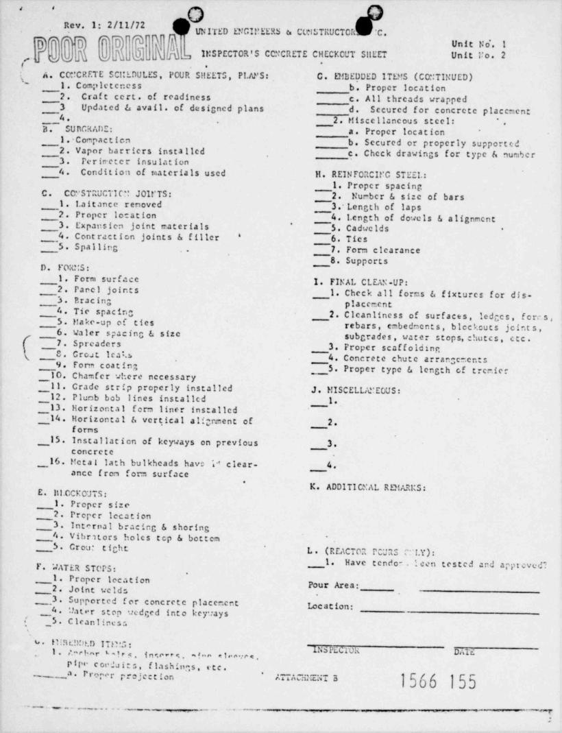
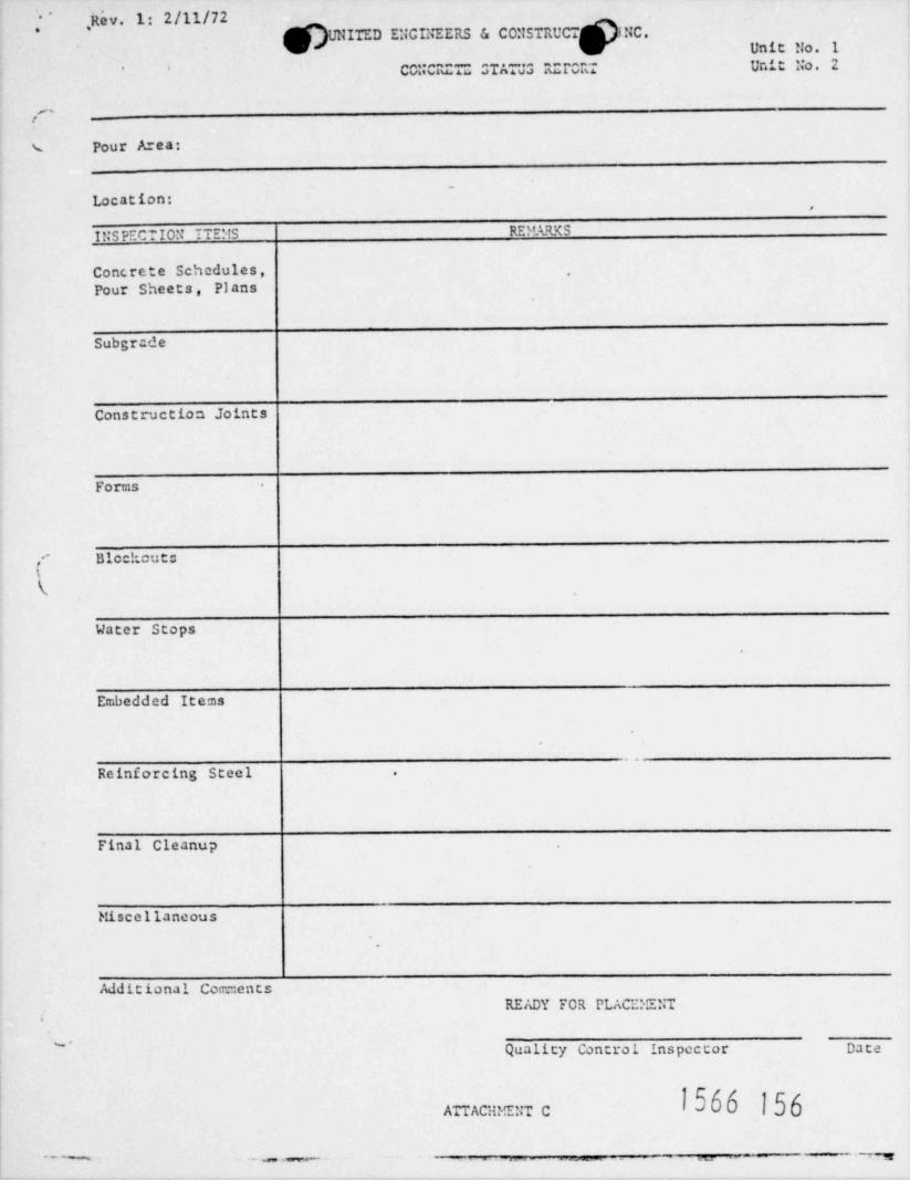
(- b. Inspectors Concrete Checkout Sheet (Attachment B) and ConcreteStatus Report (Attachment C).
Quality Control will use Attachment B & C to document pre-placementins pect ion. Items not completed or requiring correction willbe noted on Attachment C in the remarks column.
Upon satisfactory completion, items will be check-cf f inAttachment B and annotated in Attachment C.
c. Report of Concrete Placement (Attachment D).
Quality Control will use Attachment D to document inspectionof concrete placement.
d. Daily Concrete Curing Record (Attachment E).
Quality Control will use Attachment E to document daily inspectionof concrete curing activities.
2. Reports of all cetivities of Quality Control shall be submittcd tothe UESC Field r zirvisor - Quality Control f or inclusien in theQuality Control 'e and distribution to the owner and Engineer,.
as required.
. 1566 151
- _ - . _ . _ _ _ - . .-
_
D D..
'*
.
QC-1'
g3 43 M Fev 9D
'
T j(D D'
U|10|73" [: Page 14eV cv 4u .-
\J a
|L
'/III. R W 63 .'3D RF"C_M (Continued)
A copy of the continuous roll of recorder tapes for cach days3.production shall be on file at the batch plant.
11and written copics of inspection reports for concretc activitics4,and tcres chall be presented to the Field Supervisor - QualityContrci no later than the morning of the work day follouingexecution of the ucrk. These will be replaced with the typed
-
copy as ti:ay are prepared. ..
B. De ficienc !s s.
Results of all tests or inspections that do"not meet specification1.requirements shall be immediately reported to the Field Supervisor -Quality Control who shall inform the UEEC General Superintendentfor appropriate corrective action taken.
Eatch tickets shall be annotated to reflect the cause fora.rejection and the intended use for the rejected concrete.
Nan ~mformancer relati..e to concretc $tcrials,'plac;d ecneratc,h, .
rebar and caducids (per Appendix B, Paragraph 4C) shall bedocumented on a Nonconformance Recore and crocessed in acenraar. n' '
r\ with QC-17.
Deficiencies relative to practices and procedures shall bec.reported to the Field Supervisor - Quality Control for appropriate,
corrective action and concrete placement shall be halted untilall discrepant conditions have been corrected.'
In the event of a disagreement between the Field Supervisor -2.Quality Centrol and the General Superintendent as to remedialactions or =casures required to bring productica within standardQuality Control cnd the limits of the engineering specifications,it is then the duty of the Field Supervisor - Quality Control toinform the Construction Manager and request cc=pliance.
In the event corrective action is not implemented, the Field Supervisor3.Quality Control shall inform the UE&C Lead Quality Assurance Engincerand_G2v50 Quality Assurance Manager for a decision on the corrective
A Quality Assurance decision shall then be nadeaction to he tal,ca.f or the disposition and corrective action to be taken..
- -
1566 152.
.
w $8
og > O'
-
-
.,
QC-1-
Rev. 86/12/72Page 15''
VIII. REPORTS AND RECORDS (Continued),,
C. Final Accentance Inspection,
1. The Quality Control Inspector shall inspect embedded items and ,
pipe prior to the release of concrete as required herein andverify:
That all items within the secpe of QC-16 were inspected anda.documentation records were checked and found to be completeand adequate per requirements of Phase I and/or Phase II FinalAcceptance Inspection.
b. That all other items were inspected by the cognizant CraftSupervisor and indicated his acceptance by signing the ConcretePlacement Checkout Sheet (Reference Attachment A).
( 1566 153(
.
.
.,
- -
.. ..
m Y'D D QT"o
e ._3 :c. ..i.:.T...i 1. 9. :.r. n~:7 c." .ct .n . .;.. ..m. . .r .c..- . -
cc c - :'D.'.T .
..
UESC I :C. / tt.C.C.- -.r. A. r e a :
TrpenmurPou T.'11 ..,.C t.. . ., ,..C A .,.. . . . . . - .-
,
1.ne n t ion :,
UNIT 2 (Circia1.":IT 1'- -
.
f;trenat'a Snatif rcJ:
Quantitv "tequircel: Curine ''co ' d : 7ur$ hili :' -LO3d b *UTI'':;-tilx Code No.: Cenent:
Finir.h 'omuirei!? Qout : Cinns s t rite t : Verir thin -Thin -*
-
e ha1. to TourtDa te & Ti-e c Mod..,kr.s,:c~-
.
r. , . ., m'Cra f t Su v'r. 7tcld
~ '
C112C. 0L A I . .. ,. Minor ite:. to cernlete orter to:, .. . (curnare. ., .,o) . a a.r,
. daea.. alace .?nt (if nene, ,rint ona)
1. . ur f .ccPreparetic1
2. l'orr inr!:-
3. #" ' # CIMSteel
s
I.
'
( " * n .; e e c.n .-- d |:l-
>c' ou t 5
* ' ****5. Irc1
-
.
.
IJ . d'.D C!)O Y l'o10% ,
.
* '
7* Pipin:E:-b c d d- - .t s
.
8* Electric.a.1c--beddenn t:. . --
.
9. Idne anti crin!c_
I f .,.1.1 c 2 - - ..n.- . ro n - : 3. . - . r .: n r .-- .s r .. t ':. c. r - . , . . t t e -.. .
:: .: .t.-- =:. .
10. Qualit. Controle
(surn,"e) (re m r'..s)_ _ . .-..
Iten la nuit 'ic stanc.1 L co-tes iton to cencrete pl::cenent suacrvi.:or end jobEn:incer ,rior to 1:cuiu int:.ict cr.!c to b::tch car. crete.
__
-
71nt r ibu t ica :"roi. T.u- t , ;
' , . e. <: t . "ra1. 'n t.'
(, O.C. c :-v'i. (5) 1566 154un'r' r . (2)Cone. 'i,ca. c
Test 1.ah (I. )Other:: (1.l it in 10 ') Dnr1 Affice) _ _ , _
.i n '. Enn.i ice r - 'as't. .105 ..a .teJ.
AT P. .Ci:' ". -|-" A-
--
-- .. - . - - , __ _ _ _ _ _ _ _ __ _ _ _ _ , ~ . . . _ . _ .
, .
9Rev. 1: 2/11/72UNITED ENGI!!EERS a CLtlSTRUCTOR 'C .
i A Q; *D
'
3' Y gg Unit No'. 1
'66 wi .
q]. a( II:SPECTOR'S CCNCRETE C1{ECY. CUT SilEET Unit Uo. 2'-
_q .
A. CC:! CRETE SCI:EDULES, POUR S!!EETS, Pl.APS: G. E!! BEDDED ITD!S (CO::TINUED)1' l. Completeness b. Proper location
2. Craft cert. of readiness c. All threads wrapped3. Updated 6 avail. of designed plans d. Secured for concrete placement
B~~4. 2. t!isec11ancous secci: '.SUnCRADE: a. Proper location
1. Compaction b. Secured or properly supported2. Vapor barriers installed c. Check drawings for type & num5cr3. Perin eter insulation4. Condition of materials used it. REINFORCIUC STEEL.:
1. Proper spacingC. COS'STRUCTIC:' JOIt'TS: 2. Nurber & size of bars
1. 1.aitance renoved 3.' Length of laps2. Proper location 4. l.cngth of dowels 6 alignment3. Expansien joint materials 5. Cadwelds
'-
4. Cont raction joints & filler 6. Tics*
5. Spalling 7. Form clearance.
8. SupportsD. FOR!:S:
1. Form surface 1. FINAL CLEAN-UP:2. Panel joints 1. Check all forms & fixturcs for dis-3. Bracing placement4. Tic spacing 2. Clcanliness of surf aces, ledges, fores,5. trake-up of ties rebars, embedmonts, blockcuts jcint s ,6. Valcr spacing & size subgrades, water stops,chutcs, etc.
___7. Spreaders 3. Proper scaffolding8. Croat l e a t.s 4. Concrete chute arrangementsg9. Form coat ing
___5. Proper type & length of trcmier__10. Chamfer where necessary__11. Crade strip properly installed J. HISCELLAMEOUS:
12. Plumb bob lines installcd 1.~~
13. Horizontal f e nn liner installed~714. Horizontal & vertical alignment of 2.forns
__15. Installation of keyways on previous 3.concretc
__16. ifetai lath bulkheads have 'a clear- 4.d
ance fren form surface*
K. ADDITICSAL RD1 ARKS:E. Ill.CCKOUTS:
1. Proper size2. Proper Iccation
3. Internal bracing & shoring4. Vibrators holcs tcp & bottem *
5. Crou: tightL. (REACTOR PCURS : '!.Y) :
1. Have tendon. I cen tested and appt eved?F. "JATER STOPS:,
1. Proper IccationPour Area:2. Joint ucids
___3. Supported f or concrete placement Loc ation:._4 . *.'a t e r s t o p .icdged into key'tays.,' _5. C leanl ines s
b. Il!.%DDt.D ITi"5 :M PEC r0R DAld1. ,'.a e l a r '-! r s . i n e.c - e s . afon cicoece.
P f ' c oNa it s , flashin<s, etc.P
_ _.a. rr,,p.,r pre;cc: ion mACsxEaT a-
1566 155- ... _._ - _ - ..
. - -- . -
:
'Rev. 1: 2/11/72*
*
]UNITEDEUCINEERS& CONSTRUCT, fNC.*4
Unit No. 1CONCRCT:: STATU3 R;rORT Unit No. 2' '
g-
% Pour Area:
'
Location:.
It SPECTION ITEMS RE!fARKS
Concrete Schedules, "
Pour Sheets, Plans
Subgr de
Construction Joints
Forms
,' Blockcute!(
Water Stops
Embedded Items
~
Reinforcing Steel .
Final Cleanup
Miscellancous
.
Additional Corrr.entsREADY FOR PLACEMENT
,
~.Quality Control Inspector Date
1566 156ATTACHMENT C
. _ _ . . _ _ , _ . . .- .-- m - 7
..,
);
Fev. 1: 2/11/72
UNITED ENCINEERS & CCNSTRUCTORS INC.<~
,I REPORT OF\ CONCRETE PLACEMENT
Project Identification: Metropolitan Edison Nuclear Plant - Three Mile Island Unic No.,_
Pour Area: Date
Location:
FO IMS ACCEPTED RETNFORCE!ENTS ACCEPTEDProperly Coated Proper ClearanceFree From Holes Proper SupportSeams Tight CleanCican Tie Rods Type:Proper Shoring & Spacing:Support
EQUIPMENT:
No. & Size of Vibrators
Placceent Equipment
l'(
Tremic Pipes - Number Size Location
PLACEMENT:
Consolidation
Grouted Time
Concrete - Lif t Depth Direction of Pour
REMARKS:.
;
. 1566 157Quality Control Inspector Date
ATTACIPENT D
. . . .. - - - - .. .
~ ]fMTTED EIT.TNEERS & CONSTRUCT: 9NC.* '
. .
DAILY CONCRETE CURING RECORD
.
PROJ ECT: Three Mile Island Unit No. Pour No.s..
Date of Pour: Location:
.
Inspect Concrete Curing for Compliance with : Winter Curing MethodSummer Curing Method
_
Prepared By Date
dummer t uring Metiloo
[ ]Coveredwithwetburlap [ ] Scaled with curing compound(not in Reactor Building)
Data
Date
|concrete Temp. ( F)
Mint =um Temp.50 50 50 50 50 50 50Rec'. 4_rement (UF3 ,
.
,e -i
.
.
Winter Curina Method
Protection.
[ ] Insulated Forms [ ] Polyethelene, straw & tarps
[ ] Plywood Forms [ ]HeatedandVented*
Data
Date
Concrete Temp. (OF)
. . u . . .. . u ... w..ip .
ncquirement ( F) 50 50 50 32 32 32 32
REMARKS:
1566 158:',
%s '
Quality Control Inspeccor Date
ATTAC1 TENT E
. . - - . -- -- - . . - -
_ __ _ _ . . . -m
-
9 9. .
.
y~ QC-1.' App. A' Rev. 1-
.
APPENDIX A
Concrete Material( andi List of Approved Concrete Mixes
February 11, 1972
Revision 1
.
1566 159
.
--w.- . . . - ~,. .
--
.' .
.
QC-1App. A
/* Rev. 12/11/72. *
'- 1. CONCRETE MATERIALS Page 1
a. Preliminary Tests
*
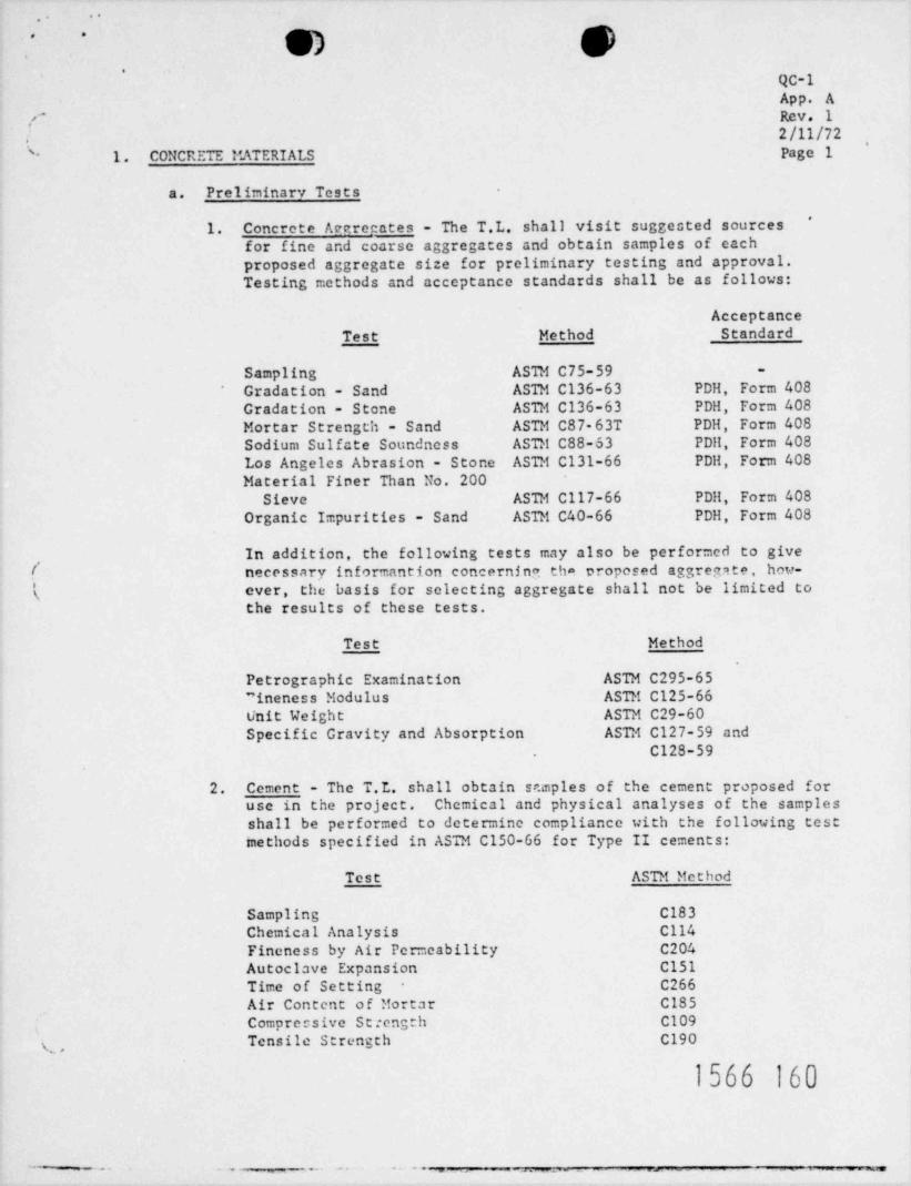
1. Concrete Accrogates - The T.L. shall visit suggested sourcesfor fine and coarse aggregates and obtain sampics of eachproposed aggregate size for preliminary testing and approval.Testing methods and acceptance standards shall be as follows:
AcceptanceTest Method Standard
Sampling ASTM C75-59 -
Gradation - Sand ASTM C136-63 PDH, Form 408Gradation - Stone ASTM C136-63 PDH, Form 408Mortar Strength - Sand ASTM C87-63T PDH, Form 408Sodium Sulfate Soundness ASTM C88-63 PDH, Form 408Los Angeles Abrasion - Stone ASTM C131-66 PDH, Form 408Material Finer Than No. 200
Sieve ASTM C117-66 PDH, Form 408Organic Impurities - Sand ASTM C40-66 PDH, Form 408
In addition, the following tests may also be performed to give,
/ necessary informantion concerning tha proposed aggregate, how-s ever, the basis for selecting aggregate shall not be limited to'
the results of these tests.
Test Method
Petrographic Examination ASTM C295-65"ineness Modulus ASTM C125-66Unit Weight ASTM C29-60Specific Gravity and Absorption ASTM C127-59 and
C128-59
2. Cement - The T.L. shall obtain sr.mples of the cement proposed foruse in the project. Chemical and physical analyses of the samplesshall be performed to determine compliance with the following testmethods specified in ASTM C150-66 for Type II cements:
Test ASTM Method
Sampling C183Chemical Analysis C114Fineness by Air Permeability C204Autoclave Expansion C151Time of Setting C266Air Content of Mortar C185Compressive Strength C109Tensile Strength C190x,,
1566 160
-. . . . . .. . .. . . - .. . --
..... . ,
.
63 53 QC-1g GN 1 pi App. A
;# * b J J|\ Rev. 1t) m2/11/72
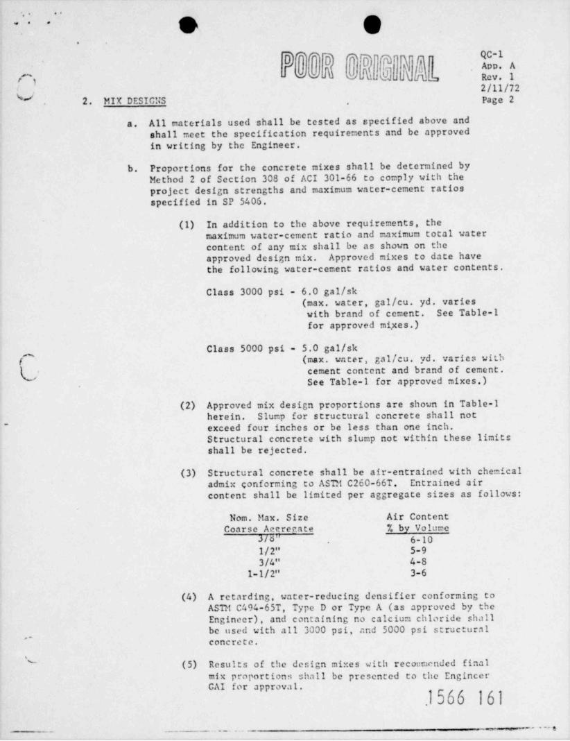
2. MIX DESICNS page 2~.
All materials used shall be tested as specified above anda.shall meet the specification requirements and be approvedin writing by the Engineer.
b. Proportions for the concrete mixes shall be determined byMethod 2 of Section 308 of ACI 301-66 to comply with theproject design strengths and maximum water-ccment ratiosspecified in SP 5406.
(1) In addition to the above requirements, themaximum water-ccment ratio and maximum total watercontent of any mix shall be as shown on theapproved design mix. Approved mixes to date havethe following water-coment ratios and water contents.
Class 3000 psi - 6.0 gal /sk(max. water, gal /cu. yd. varieswith brand of cement. See Table-1for approved mi,xes.)
Class 5000 psi - 5.0 gal /skf
(max. water, gal /cu. yd. varies with,,
(,j cement content and brand of cement.See Table-1 for approved mixes.)
(2) Approved mix design proportions are shown in Table-1herein. Slump for structural concrete shall not
- exceed four inches or be less than one inch.Structural concrete with slump not within these limitsshall be rejected.
(3) Structural concrete shall be air-entrained with chemicaladmix conforming to ASTM C260-66T. Entrained aircontent shall be limited per aggregate sizes as follows:
Nom. Max. Size Air ContentCoarse Accrecate % by Volume
J/d" 6-101/2" 5-93/4" 4-8
1-1/2" 3-6
(4) A retarding, water-reducing densifier conforming toASTM C494-65T, Type D or Type A (as approved by theEngineer), and containing no calcium chloride shallbe used with all 3000 psi, and 5000 psi structural
,,
concrete.
(5) Results of the design mixes with recommended final"
mix proportions shall be presented to the EngincerCAI for approval.
.1566 161
- _. .. . .. . ,
h, 4
QC-1' * App. A
Rev. 1-*
2/11/72f'
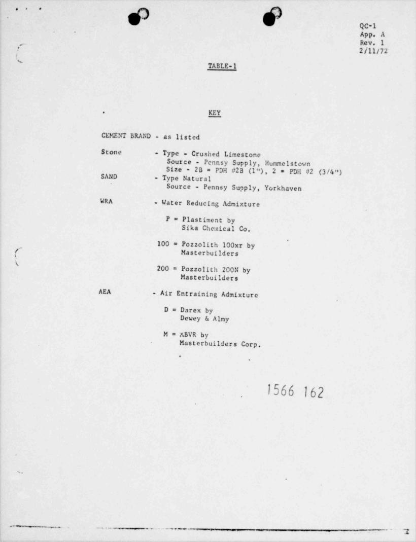
TABLE-1
KEY-
CEMENT BRAND - as listed
Stone - Type - Crushed LimestoneSource - Pennsy Supply, HummelstownSize - 2B = PDH #2B (l"), 2 = PDit #2 (3 /4 ")
SAND - Type Natural
Source - Pennsy Supply, Yorkhaven
WRA . Water Reducing Admixture
P = Plastiment bySika Chemical Co.
'
(,100 = Pozzolith 100xr by
Masterbuildersk
200 = Pozzolith 200N byMasterbuilders
AEA . Air Entraining Admixture
D = Darex byDewey & Almy
M = r.BVR byMasterbuilders Corp.'
.
1566 162.
.
9
-- --- _ , . -_ . . . . _
__ ___
_
7
.
! e - ?.E- 1 /Ns ..
,' '
..
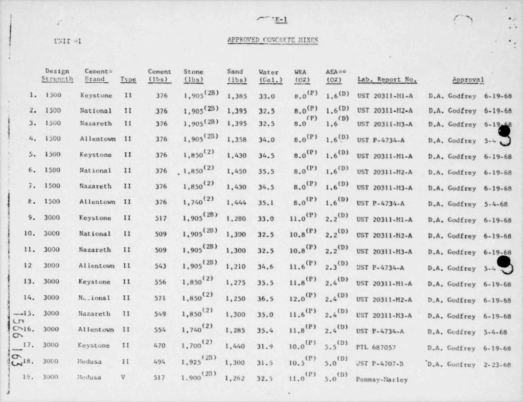
GIT "I APPROVED CO''CRETC MIXES -
.
f
.-
Design Cement * Cement Stone Sand Water WRA AEA**Strennth Brand Type (Ibs) (1bs) (Ibs) (Gal.) (02) (02) Lab. Report No. Approval
1. 1500 Keystone II 376 1,905(2B) 1,385 33.0 8.0 1.6W UST 20311-M1-A D.A. Godfrey 6-19-68',
W) 1.6(D) UST 20311-il2-A D.A. Codfrey 6-19-682. 1500 fiational 11 .376 1,905(2B) 1,395 32.5 8.0
3. 1500 fiazareth 11 376 1,905(23) 1,395 32.5 8.0 1.6 UST 20311-M3-A D.A. Godfrey 6-19 8
4 1500 Allentown II 376 1,905(23) 1,358 34.0 8.0 1.6 ?) UST P-4734-A D.A. Godfrey 5-4E' I
5. 1500 Keystone II 376 1,850(2) 1,430 34.5 8.0(P) 1.6 UST 20311-M1-A D.A. Godfrey 6-19-68'
6. 1500 National II 376 ,1,850(2) 1,450 35.5 8.0(P) 1.6(D) UST 20311-!!2-A D.A. Godfrey 6-19-68'
7. 1500 tiazareth II -376 1,850(2) 1,430 34.5 8.0 1.6 UST 20311-M3-A D.A. Godfrey 6-19-68
2)E. 1500 Allentown II 376 1,740 1,444 35.1 8.0(P) 1.6 UST P-4734-A D.A. Godfrey 5-4-682B )9. 3000 Keystone II 517 1,905 1,280 33.0 11.0 2.2 UST 20311-M1-A D.A. Godfrey 6-19-68
2B) '10. 3000 flational II 509 1,905 1,300 32.5 10.8 2.2 UST 20311-M2-A D.A. Godfrey 6-19-68
'11. 3000 Nazareth II 509 1,905 1,300 32.5 10.8 2.2 UST 20311-M3-A D.A. Godfrey 6-19-68
'12 3000 Allentown II 543 1,905 1,210 34.6 11.6 2.3 UST P-4734-A D.A. Godfrey 5-4
13. 3000 Keystone II 556 1,850(2) 1,275 35.5 11.8(P) (D) UST 20311-M1-A D.A. Godfrey 6-19-68$
2) '14. 3000 Nc. . i ona l II 571 1,850 1,250 36.5 12.0 2.4 UST 20311-M2-A D.A. Godfrey 6-19-6S
'-15. 3000 Nazareth II 549 1,850 1,300 35.0 11.6 2.4 UST 20311-M3-A D.A. Godfrey 6-19-68' 'O l 6. 3000 Allentown II 554 1,740 1,285 35.4 11.8 2.4( ' UST P-4734-A D.A. Godfrey 5-4-68m'17. 3000 Keystone II 470 1,700 1,440 31.9 10.0 5.5 PTL 687057 D.A. Godfrey 6-19-68-
& ( 23 )18 3000 11edusa II 494 1,925 1,300 31.5 10.5(P) (D) .
5.0 UST P-4707-3 D. A. Godf rey 2-23-68u.
' 19. 3000 itedusa V 517 1.900 1,262 32.5 11.0 5.0 Penns y-Ma r ley
,a .
. Ihl; LIM *e .-t' -1 s
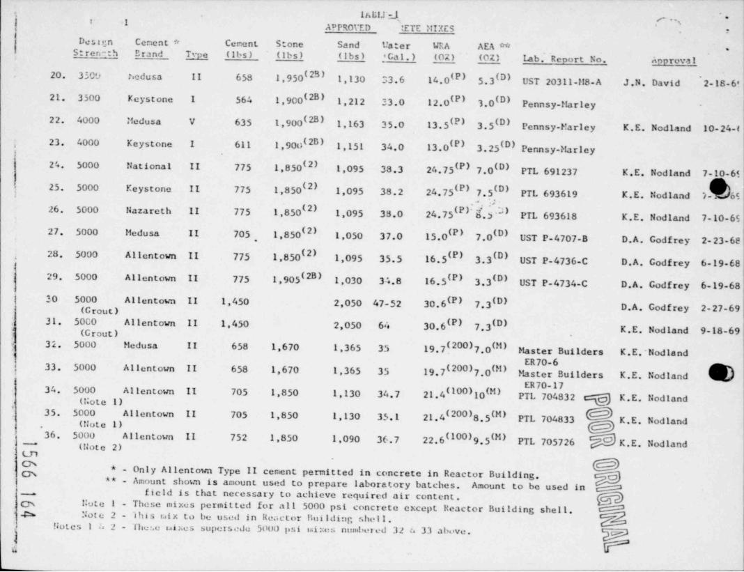
APPRorED ETE MIXES *
De s t ,;n Cement * Cement Stone Sand Uater URA AEA ** -S t rere -h Brand Type (lbs) (Ibs) (lbs) ' Cal.) (02) (OZ) Lab. Renort No. Approval
20. 3509 hedusa 11 658 1,950(2B) 1,130 33.6 14.0(P) 5.3(D) UST 20311-l!8- A J.N. David " 2- 18- 6'
21. 3500 Keystone 1 564 1,900(2B) 1,212 33.0 12.0(P) 3.0(D) Pennsy-flarley -
22. 4000 Medusa V 635 1,900(2B) 1,163 35.0 13.5(P) 3.5(D) Pennsy-Marley K.E. Nodland 10-24-f23. 4000 Keystone I 611 1,900(2B) 1,151 34.0 13.0 3.25(D) Pennsy-MarleyE),
2'. 5000 National II 775 1,850(2) 1,095 38.3 24.75(P) 7.0(D) PTL 691237 K.E. Nodland 7-10-6125. 5000 Keystone II 775 1,850(2) 1,095 38.2 24.75 I 7.5(D) PTL 693619 K.E. Nodland 7- os
'. :s
26, 5000 Nazareth II 775 1,850(2) 1,095 38.0 24.75 I.5 PTL 693618 K.E. Nodland 7-10-6527. 5000 Medusa II 705, 1,850(2) 1,050 37.0 15.0 7.0 UST P-4707-B D.A. Godfrey 2-23-68
) EI
28 5000 Allentown II 775 1,850(2) 1,095 35.5 16.5 3.3 UST P-4736-C D.A. Godfrey 6-19-68E) 0),
;
29. 5000 Allentown II 775 1,905(2B) 1,030 34.8 16.5(P) 3,3 UST P-4734-C D.A. Godfrey 6-19-680)
30 5000 Allentown II 1,450 2,050 47-52 30.6(P) 7,3 D.A. Godfrey 2-27-69W)
(Grout)31. 50C0 Allentown II 1.450 2,050 64 30.6 7.3 K.E. Nodland 9-18-69
E) EI(Grout)
32. 5000 Medusa II 658 1,670 1,365 35 19.7{200)7.0INI Master Builders K.E.'NodlandER70-633. 5000 Allentown II 658 1,670 1,365 35 19.7(200)7.0IM) Master Builders K.E. NodlandER70-1734. 5000 Allentown II 705 1,850 1,130 34.7 21.4(100)10IM) PTL 704832 g K.E. Nodland(!;ote 1)
'35. 5000 Allentown II 705 1,850 1,130 35.1 21.4(200)8.5(M) PTL 704833 K.E. Nodland
' (Note 1)36, 5000 Allentown II 752 1,850 1,090 36.7 22.6(100)9.5IN) PTL 705726 K.E. Nodland~
(Note 2)Ln
* - Only Allentown Type II cement permitted in concrete in Reactor Building.** - Amount shown is amount used to prepare laboratory batches. Amount to be used infield is that necessary to achieve required air content._
m Note 1 - These mixes permitted for all 5000 psi concrete except Reactor Building shell.* -Ch Note 2 - ibis uix to be used in Reactor !!uilding shell .
Notes 1a 2- these uixes supersedu 5000 psi uixc4 numbered 32 n 33 above. pn
..,
.
QC-1App. ERev. 1, . .
'
2/11/72's,
APPEtmIX B
Reinforcing Steel *
andI Cadwelding\
February 11, 1972
Revision 1
.
1566 165
t
+ - - _ .... _ _
, -- - , _ , ,, . . . . . - a
...
. .. . , ,
.
QC-1App. B
D * *fD
#3 M'V Rev. 1"
,.2/11/72| 1. REI!:FORCTMG STEEL , yy g gJ '
s Page 1(a. Mill Test Renorts
1. Mill test reports of chemical and physical analysesshall be furnished on delivery for all reinforcing steel .
received on the site, and shall be reviewed f or conformanceto the following specification requirements:
Sizes up to #11 bars - ASTM A15, Grade 4.1 and Grade 60Size 14S and 18s bars - ASTM A615, Grade 40 and Grade 60
b. Storace
1. Reinforcing steel, when received is bundled and metal-taggedby heat and size.
2. Bars shall remain bundled and tagged until User Tests are completeand results found acceptable.
3. A storage yard log is maintained shouing material received,sampled, tested, and accepted for use. The log is kept up
to date by the Field Supervisor - Quality Control and is ouditedby the Quality Control Group.
( 4. Any steel which does not pass inspection or test requirementswill be immediately removed from the site.s
5. Reinforcing steci indicative of " tests still unresolved" willnot be released for construction.
6. When user tests are complete and found acceptabic, materialis released for construction.
c. User Tests
1. UESC Quality Contr'o1 personnel shall select from each heat andsize of rebar received at the site, two spriimens per sampic lotfor testing to determine the yield point, u.timate streur,th andpercent elongation. These rebar tests will be termed "Uccr Tests"and calculations shall employ the actual measured cross sectionalarea of the specimen and not the nominal area. ( A sampic lot isdefined as material of one heat weighing 25 tons or less).
2. Whan a f ailure is noted in the User Tests, resampling will beconducted on twice tha number of samplas as originally celectedand tested. tihen all of the resampics pass, the lot representedby the sample shall be cc taidered acceptable. Only two recamplingsof a lot will be permitted. Failure of the second resampics shall
be cause for rejection of the represented lot..
1566 166'~
_ _ _ . . . . _ __,,_ ,,,...-.. _ 3_
"
q Q.: ..
QC-1.
App. B
.^ Rev. 1/ 2/11/72( Page 2
2. WELDED WIRF. FAP2IC
a. A letter of compliance will be required on welded wire fabricverifying conformance to ASTM A185-64.
3. CAD'JELD SPLICES
a. Sizes
Reinforcing steel bars larger than #11 shall be spliced with the"Cadweld" process,
b. Mill Test Renorts
Mill test reports for splicing sleeves will be required and reviewedfor compliance with Specification requirements. Rejected materialwill be returned to the Vendor or otherwisc removed f rom the s ite.
c. Qualifientions of Ccdweld Operators pg #%' '[.1
1. Prior to production work, the operator designated to perf orm *C"Cadweld" splicing will be qualified by preparing : test joint
for each bar size and position he will be required to splice.,-
i These test joints will be tested in cension af ter visual examination .' If the test splice develops the minimum specified ultimate strength
of the bar (A615 - Gr. 40, 70 ksi and A614 - Gr. 60, 90 ksi) theoperator shall be considered qualified to produce that size andposition of splice.
2. Using previously qualified operators, approximately fif ty spliceswill be prepared under production conditions. From these splices,at least sixteen will be randomly scicceed and tested to doctruction.Results of these tests will be turned over to the Engineer forevaluation and determination of the initial sampling rate forproduction splices.
3. In qualification of both pre production and production splices,each completed splice shall meet the following acceptance standards:
(1) Sound filler metal shall be visibic at both ends of the splices1 cove and at the top hole in the center of the sleeve. (Asingic shrinkage bubbic present below the riser is notdetrimental and should be distinquished from general porosity.)
(2) There shall be evidence of filler metal between the sleeveand bar for the full 360 , however, splice sleeves which arenot exactly concentric or axially aligned with the bars areacceptabic. Filler metal void limits shall be as shown in,
Figure 1.-
.-
1566 167
- . . . .-___ --
_
__-
*....
. .. .
.
QC-1App. BRev. 1
/ 2/11/72( Page 3
3. CADt? ELD SPLTCES (Continued)
(3) The bar ends shall be clean and free from rust, millscale, slag, grease, paint, moisture, etc.
(4) Bars shall be longitudinally centered in the sleeves asshown by previously affi::ed center punch marks or similaridentifiable location marks on the bar.
(5) Bars shall not be scarfed and the portion of the bar in thesleeve shall have uniform deformations along its length
'
consistent with the rolled mill pattern.
d. Cadweld Inreeetion
Cadwelding in the containment structure shall be inspected byQuality Control for the following requirements:
1. "When the relative humidity is over 807., molds and bar ende shallbe heated above 212 F but not more than 300 F and the bar endsthen uire brushed to remove all loose mill scale, corrosion,concrete, and other foreign materials. The bar ends shall then
Cbe reheated to 212 F - 300 F. Any bar not fired within 5 ninutesf of 2nd heating shall bc reheated to 212 F - 300 F."(
2. Sleeves and crucibics shall be checked for cleanliness, rust, etc.
3. tbids to be preheated when necessary (new mold or change of shif t).
4. Bar ends shall be free from loose mill scale, rust, moisture, slag,grease, and paint.
5. Bars shall not be scarfed.
6. Bars shall be marked by center punching or othe r suitable means,so that assurance ai centering ends within the sleeve may be made.
7. Completed splices shall be visually inspected in accordance withthe following procedure. Any splice which, in the judgment ofthe inspector does not pass visu'al inspection, shall be cut out andreplaced.
(1) Properly made splices will have filler metal visible at bothends of the sleeve and at the top hole in the center of thesleeve.
1566 168
. ...
*...
... .
*QC-1App. BRev. 1
.'' 2/11/72Page 4*
3. CADRET,D SPLICES (Continued)
- (2) Filler metal need not flow to the very edge of the sleevedue to the gasket action of the asbestos wicking used toseal in the molten filler metal.
(3) As a result of the Cadweld process, a shrinkage bubbic mayba visibic at the top hole, where the molten metal isintroduced and shrinkage fissures and pinholes may be visibleat the top of a vertical splice. These casting flows do not
adversely affect the physical performance of the splice andtherefore do not consitute cause for rejection.
(4) Filler metal void limits shall be as shown in Figure 1.
4. CADRELD TESTS
a. Sampling
1. Random sampics of visually acceptable splices at a rate to bespecified by the Engineer shall be selected, cut f rom t hestructure and tested in tension to destruction.
, . -
! b. Test Recore(
1. For each Cadweld splice,. data shall be recorded on rebar datasheets showing:
(1) Splice number (This number shall also be applied to thesplicing sleeve using a heat and weather resistant markingpencil).
(2) Location
(3) Size and orientation of the splice.
(4) Operator number (crew number)
(5) Date, weather conditions , and time the splice was made.
(6) Inspectors initials
(7) Sample number and test result, if applicabic.
1566 169
.
P" g Nb _$'F *W"* **O N__
__ , ,yM Y
- - - . - .
-
. . . . .. ,, ;
..
* .
QC-1App. BRev. 1<
I 2/11/72% . Page 5
4. CAD'JT.LD TESTS (Continued),
Cadweld Failurec.
fail to meet tension test results less thanCadweld splices that1.70,000 psi or 90,000 poi as applicable will be cause for additionalsampling. The next previous or subteiuent splice made by thesource operator shall be cut from the structure and tested intension to destruction. If this test exceeds the minimum value
If this splice alsothe process will be considered in control.fails, the operator / crew responsible shall discontinue cadweldingand an engineering evaluation will be made.
1566 170
r.
.
f
e
a
I
- - - . . . - _ , .
.
...'
rigure-1 }. . ,, , .
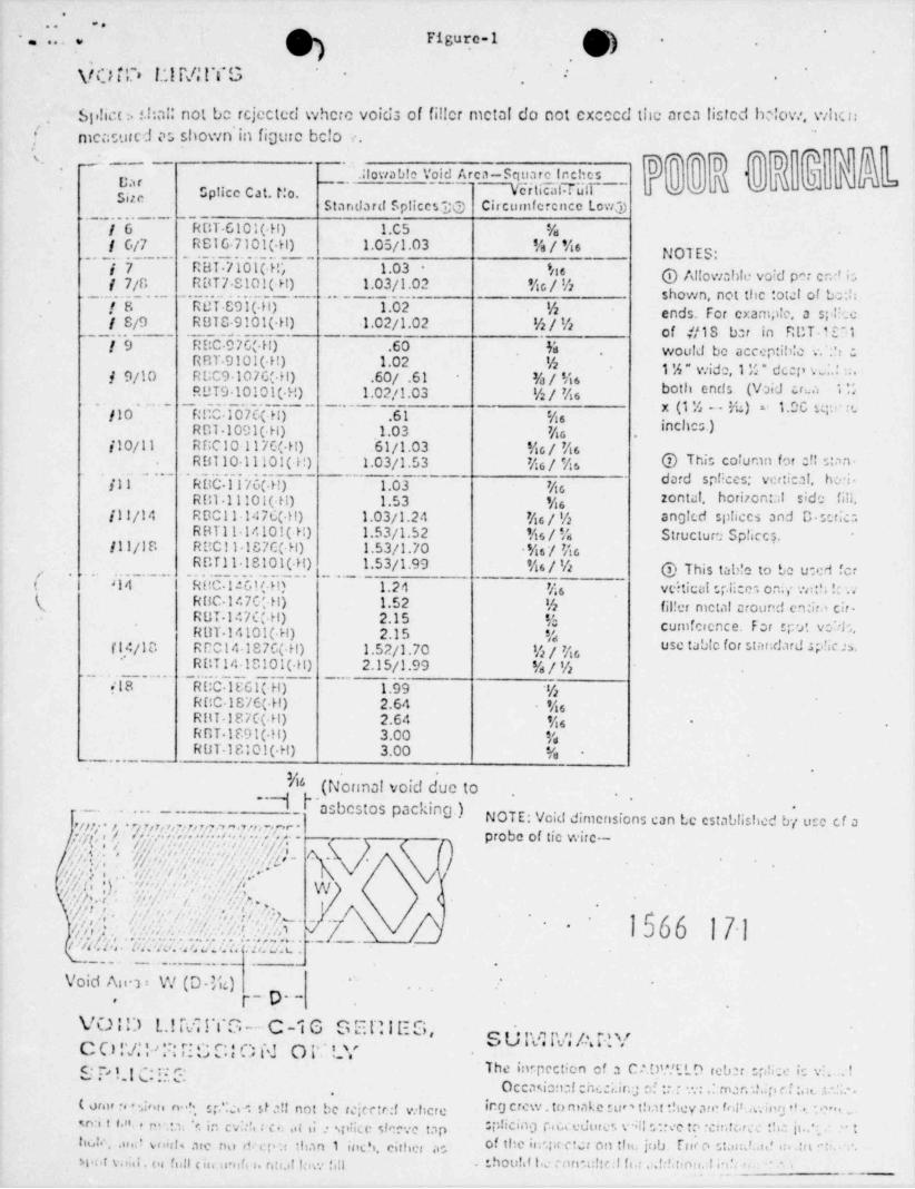
V O T D !!.l M I T G - -.
si,!ia n s.hal: not bc rcjected where voids of filler metal do not excccd the arca listed hc|ow, whcn/
-
measured n shown in figure bclo
T]i mo m~ ~ ~ '~~ ~ ~
.;fowabic Void Arca-Square lcchts' ] ~ "k
'Car o- -- - --
3I"' Sptice Cat. Mo. Vc~r tiliitTdlT~'-~ 6C DStar dard Splices'DQ Circumference Low 3
/6 RUT 6101(.H) 1.C5 %/ 6/7 RS16 7101(.H) 1.05/1.03 %/Ms NO1 ES-/7 R BT.7101( H- 1.03 - 'e s @ Allowahti. void par cr/' i:.,
/ 7/n RBT7 S101(.H) 1.03/1.02 b/% shown, not the total of bc:b. _ . . . . _ _ . .
. . . . . ROT 891( H). _ _ _ -. . .
1.02_..- % ends. For exampic, a sp|i. e*8.
t
/ S/9 RB10 9101(.H) .l.02/1.02 %/% of //1S bar in RCTd En1_ _ _ . .f9 R DC.9 7C(.H) .60 'Is, woult! be accep:ih!c . ,S .,
. _ _ . _ . . . _ .
RBT 9101(.H) 1.02 % 1 %" wide,1 % * dcop L' ' .f 9/10 R UC9 107G(.H) .60/ .61 %/M6both ends (Void crua .MR UT910101( H) 1.02/1.03 %/ b
- x (1 % _ . E) e 1.D t, n; . : <.-
fl0 RCO 107t(.H) .61 %sR Dl .1091(.H) 1.03 b inchN
j10/11 RCC10117C(.H) .61/1.03 b/bRB110 ll101( !!) 1.03/1.53 h/b @ This column f'w :,1 cam.
dard sp!!ces; ver:ical, han-fil RUC ll76(.H) 1.03 Mc
RU1 11101(-H) 1.53 b zon tal. horizon::.I sid': fili./11/14 R D0 l l .147C( H) 1.03fl.24 b/% angicd spliecs and ,, scric;o
RBTl 1 1410!( H) 1.53/1.52 b/% Structur ; Sp!iccs./11/18 R UC l l .187C(.H) 1.53/1.70 b/b
R u r l l .18101( _H) l.._.1.53/1.99 b/% @ This tab'c to be used for,,
( J14. . . _ . .. . _ . . . . . . _ _ . _
RBC-1.:G1/ H) 1.24 b VeitiCUI "ili:C i O n >' W : ,"!'-
( RUC-147C H) 1.52 % fil!er metal croond en: ira cir-RUT 147C(.H) 2.15 % cumicience. For sp a: vo'd .RUT.14101( H) 2.15 %
(14/18 Rr014187C(.H) 1.52/1.70 %/ use tabic for star;dard piic n.R DT 14 10101(.H) 2.15/1.99 %/%
.18 RUC 10Gl(-H) 1.99 '%RUC IS7E( H) 2.64 bRHT 187C(.H) 2.64 -
RBI.1891(.H) 3.00 %R U T.18 : 01(.H) 3.00 %- -...-
3*'
I~a(Normal void due tosbestos packing.)NOTE: Void dimensions can Le established b,5 se cf aurin. i i- m . . . . , , , ..s. , . , , , . .y ( , / - /,ri r, ,,,p ?,7, ,,,n .? . i, . .,- - probe of tic wirc--',-
sit , . ,i,'
' //p - -- |i;?! y' ,, ' fh'.;,,l', f'ic , ,'t!, ~i, c,i,i,; Ai
i .:// / * . - // ~ ',' * *||| ' '/ L ,' W, i } s
',,
'
,,yh.c;). :',;' ", :', l' Wn -,
/. i. 'c'+,,,'
)'/E,;.-
' ' -
*,,
/ : /i .{ | , o . . .'t, ; c,, ., /, ;, , ,, ,, . ; i, _.i ,
._ _ . . . . . _ _ . . _ _ .
Void Ama: W (D.W)p p..,
VO:D LIM!YG-C 'iG SEnlES'- SU M M ARY
C O r/,'.'.> :.::,.Ti C C ' O t J O P.' LY" * ' ' g " ' '' The intpection cf a Ct.D'.*!ED rebar sr,0 ic , . . !c. ,, .,,
Occasion:! cnce,. ira n' :- - - .: m.:r. 1.~p ri..a -,
( on u r. < ,i, n n. .'., s r. ;;c.- sf a!! not be tekctr:f vehcre ir O crew .to make rur' that they an fop-e.ing t'..*
m"1_IIv n tf.n.,r '' OP CI"O Id ''d"'c'. r;il ", ec t:i re m tcr c . 'h.: jt.. , :' . in cv. A : c ..i u pht e s!''~ce tap< s
btNe .us; ? vf dgl5 afC rhi di ep Ibafl I iDCh, cilher iis i' OM h- OM 'd 'h Ul *
H.. t v.mi os full < in n ofi s. nn. ! f ace h!! : h00!'I I s C ""'G h C I h ; 'H f' D" I ;"'' '.
.
.
.
QLTSTION 17:
" List locations where concrete tests were made referred to inQuestion 16."
RESPONSE:
Slump tests, air entrainment tests and temperature tests were per-formed for each 50 cubic yards of concrete poured in the containnent.Test cylinders used for compressive strength tests were taken daily fromeach 50 cubic yards of concrete or portion thereof placed per class.(See attached UELC Quality Control Procedure No. 1, Rev. 8).
1566 172.
.
\
*.
.
.
.
!
.
e- -7I* * **% ,,,,y.S*,,, ,e- - * *-
_ _, ,
.
O O.
.
QUEST 10:! 18:
" Describe in detail the flood protective measures and the enount oftime required to institute these measures if another "Agnes" type floodoccurred."
RESPO:SE:
The enclosed copy of Emergency Procedure #1202-32, entitled " FloodControl", describes in detail flood protective measures for TMI station.In the development of this procedure, the time required to instituteall censures necessary to ensure the continued safe operation or timelyshut.down of the station as a function of the rate of increased riverflov was taken into consideration.
The river flow at TMI as a result of the June 1972 "Agnes" floodwas approximately 900,000 CFS. Should another flood of this magnitudeoccur a flood Alert uould be initiated by the Station Superintendentwhen river flow reached 640,000 CFS. This flood Alert would not requirea shutdown of the plant.
.
1566 173-
.
.
!
.
*N**** 4 = + we* e -' ,&__, . , Nm , _. N -M N 6 ,me** *N*_