Embed Size (px)
Citation preview

Pub No. UG CL-01-10 August, 2013
G1-205-CL01
General Data Company
ID/Positive CL-01
Laser Cassette Marker User Guide
General Data Company, Inc. 4354 Ferguson Drive
Cincinnati, Ohio 45245 www.general-data.com
Page 2
Copyright© 2009 General Data Company. All rights reserved This document may not be copied in whole or in part or reproduced in any other media without the express written permission of General Data Company. Please note that under copyright law, copying includes translation into another language. Contact General Data Corporate Headquarters 4354 Ferguson Drive Cincinnati, Ohio 45245 Tel. 513-752-7978 Fax 513-965-3626 User Resources and Customer Support Contact your General Data representative for customer support. For the latest information on General Data products and services, please visit the General Data website at: www.General-Data.com Scope This document contains basic information on the use and operation of ID/Positive Laser Cassette Marker and assumes you have received basic training on the instrument. Please contact your General Data representative for information not provided in this manual. This manual does not provide instructions for the installation or upgrade of hardware. Introduction The ID/Positive Laser Cassette Marker is designed to generate a unique identification mark in the form of high-resolution linear bar codes, two dimensional bar codes and text onto ID/Positive Cassettes hence reducing errors due to misidentification of cassette blocks or specimen slides caused by illegible handwriting. The ID/Positive Laser Cassette Marker comes equipped with 1 magazine with a capacity to accommodate 70 ID/Positive Cassettes. Optional additional magazines are available for easy cassette style or color changes. Intended Use The ID/Positive Laser Cassette Marker is intended for imprinting identification marks on ID/Positive Tissue Cassettes. Installation Procedure The ID/Positive Laser Cassette Marker and associated software must be installed, and instrument performance is to be verified, at the customer site by trained General Data representatives. Relocation Procedure Contact your General Data representative before relocating your ID/Positive Laser Cassette Marker. Disclaimers This manual is not a substitute for the detailed operator training provided by General Data, or for other advanced instruction. A General Data representative should be contacted immediately for assistance in the event of any instrument malfunction.
ID/Positive CL-01 Laser Cassette Marker
Page 3
Table of Contents | ID/Positive Laser Cassette Marker User Guide
Table of Contents General Data Company ........................................................................................... 1
ID/Positive CL-01 ...................................................................................................... 1
Section 1 | Safety ..................................................................................................... 5
Caution Symbol .............................................................................................................................. 5
Chemical Safety ............................................................................................................................. 5 Optical/Laser Safety ....................................................................................................................... 5
Operational Safety .......................................................................................................................... 6
Electrical Safety .............................................................................................................................. 7
Mechanical Safety .......................................................................................................................... 7
Section 2 | System Specifications ........................................................................ 11
Section 3| LabeLase Producer CL® ...................................................................... 12
Creating or changing the password .............................................................................................. 12
Magazine Low .............................................................................................................................. 16 Magazine Empty ........................................................................................................................... 16
Deleteing a Job in the Queue ....................................................................................................... 17
Deleting the entire Job Queue ...................................................................................................... 17
Reprioritizing the Print Queue ...................................................................................................... 18
Section 4 | Operating the ID/Positive Laser Cassette Marker ............................ 19
Loading Cassette Magazines ....................................................................................................... 20
• Safety Interlocks.................................................................................................................. 22 Mechanical Switches .................................................................................................................... 22 Mechanical Design ...................................................................................................................... 23
Password Security Access ........................................................................................................... 23
Fuse Replacement ....................................................................................................................... 24
Section 5 | Maintenance ........................................................................................ 25
Laser Lens Cleaning..................................................................................................................... 25
Locating the Laser Lens ............................................................................................................... 25
Cleaning the Laser Lens .............................................................................................................. 26 Cleaning the Filtration Intake Tubes............................................................................................. 28
Cleaning the Intake Tube ............................................................................................................. 28
Cleaning the Optical Sensors ....................................................................................................... 29
Page 4
Locating and Cleaning the Sensors ............................................................................................. 29
Cleaning the Cassette Transport Path and Solenoid Plunger ...................................................... 31
Filter Replacement ....................................................................................................................... 32
Replacing the Pre-Filter ................................................................................................................ 32 Replacing the Main Filter .............................................................................................................. 34
Troubleshooting the Main Filter Unit ............................................................................................ 36
Appendix A | Backing up Printer Configuration and Layout Format Files ....... 37
Exporting Printer Configuration Files ............................................................................................ 37
Importing Printer Configuration files ............................................................................................. 40
Appendix B | Laser Safety .................................................................................... 41
Laser Hazard Classifications ........................................................................................................ 41
Control Measures for Laser Classifications .................................................................................. 42 Biological Effects of Laser Irradiation ........................................................................................... 43
Eye Injury ...................................................................................................................................... 43
Thermal Injury ............................................................................................................................... 43
Skin Injury ..................................................................................................................................... 43
Appendix C | Symbol Definitions ......................................................................... 44
ID/Positive CL-01 Laser Cassette Marker
Page 5
Section 1 | Safety
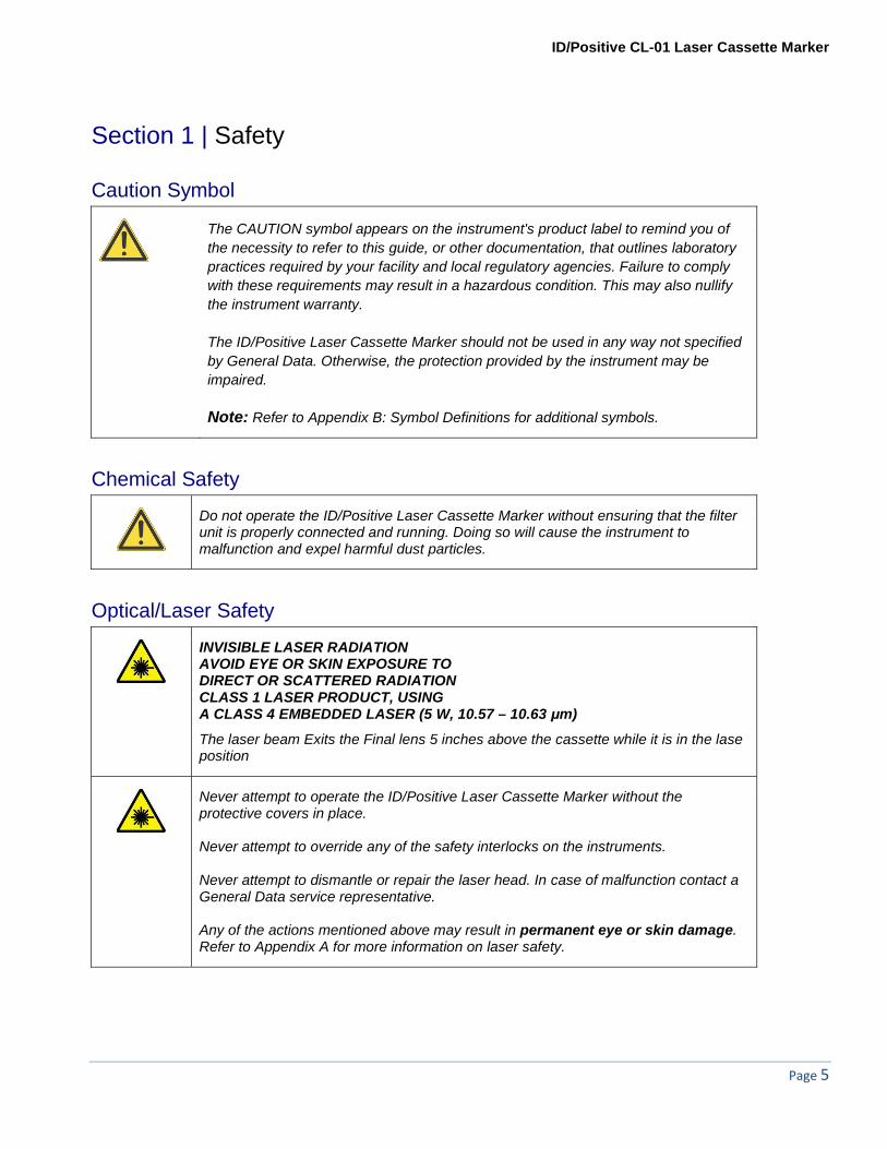
Caution Symbol
The CAUTION symbol appears on the instrument's product label to remind you of the necessity to refer to this guide, or other documentation, that outlines laboratory practices required by your facility and local regulatory agencies. Failure to comply with these requirements may result in a hazardous condition. This may also nullify the instrument warranty. The ID/Positive Laser Cassette Marker should not be used in any way not specified by General Data. Otherwise, the protection provided by the instrument may be impaired. Note: Refer to Appendix B: Symbol Definitions for additional symbols.
Chemical Safety
Do not operate the ID/Positive Laser Cassette Marker without ensuring that the filter unit is properly connected and running. Doing so will cause the instrument to malfunction and expel harmful dust particles.
Optical/Laser Safety
INVISIBLE LASER RADIATION AVOID EYE OR SKIN EXPOSURE TO DIRECT OR SCATTERED RADIATION CLASS 1 LASER PRODUCT, USING A CLASS 4 EMBEDDED LASER (5 W, 10.57 – 10.63 μm)
The laser beam Exits the Final lens 5 inches above the cassette while it is in the lase position
Never attempt to operate the ID/Positive Laser Cassette Marker without the protective covers in place. Never attempt to override any of the safety interlocks on the instruments. Never attempt to dismantle or repair the laser head. In case of malfunction contact a General Data service representative. Any of the actions mentioned above may result in permanent eye or skin damage. Refer to Appendix A for more information on laser safety.

Page 6
Operational Safety
Routine maintenance of ID/Positive Laser Cassette Marker is required for maintaining system integrity and proper operation. Maintenance must be carried out as specified in this manual. Refer to Section 5: Maintenance for more information.
Do not attempt to install or re-locate the ID/Positive Laser Cassette Marker. Doing so may result in corruption, of data and/or malfunctioning instrument. For Cassette Marker installation contact a General Data service representative.
Do not attempt to install or re-install the ID/Positive Laser Cassette Marker control software. Doing so may result in corruption, of data and/or malfunctioning instrument. For software installation contact a General Data service representative.
Do not operate the ID/Positive Laser Cassette Marker without ensuring that the filter unit is properly connected and running. Doing so will cause the instrument to malfunction and expel harmful dust particles.
Locate the ID/Positive Laser Cassette Marker only on a sturdy flat surface. Position the ID/Positive Laser Cassette Marker so that the front and rear operation panels are easily accessible by the operator.
The ID/Positive Laser Cassette Marker is intended for Indoor use only. Altitude up to 2000m, operating temperature 5 to 40 degrees C, 80% maximum relative humidity, rated 100-240Vac (max range of 90 to 264Vac), overvoltage category, II, pollution degree 2, IPX0
Please be aware that some discoloration to the ID/Positive Cassettes can occur when they are subjected to reagents containing picric acid, e.g. Bouin’s Fixative.
Please be aware that degradation or loss of text printed text on ID/Positive Cassettes may occur when they are subjected to solutions containing strong acids for extended periods of time. Decalcification processes of tissue in ID/Positive Cassettes involving strong acids such as hydrochloric acids or nitric acids should always be validated by the users prior to implementation.
ID/Positive CL-01 Laser Cassette Marker
Page 7
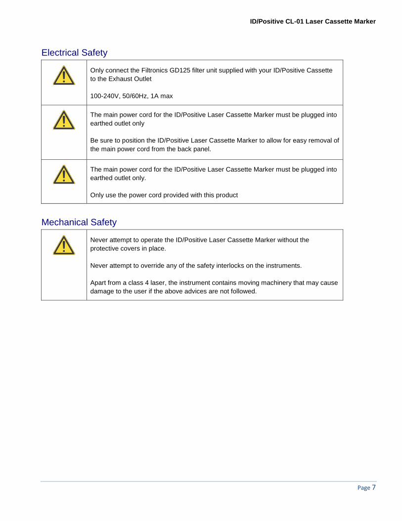
Electrical Safety
Only connect the Filtronics GD125 filter unit supplied with your ID/Positive Cassette to the Exhaust Outlet 100-240V, 50/60Hz, 1A max
The main power cord for the ID/Positive Laser Cassette Marker must be plugged into earthed outlet only Be sure to position the ID/Positive Laser Cassette Marker to allow for easy removal of the main power cord from the back panel.
The main power cord for the ID/Positive Laser Cassette Marker must be plugged into earthed outlet only.
Only use the power cord provided with this product
Mechanical Safety
Never attempt to operate the ID/Positive Laser Cassette Marker without the protective covers in place. Never attempt to override any of the safety interlocks on the instruments. Apart from a class 4 laser, the instrument contains moving machinery that may cause damage to the user if the above advices are not followed.

Page 8
Konformitätserklärung Déclaration de conformité Declaración de Confomidad Verklaring de overeenstemming Dichiarazione di conformità We/Wir/ Nous/WIJ/Noi General Data, Company, Inc. declare under our sole responsibility that the product, erklären, in alleniniger Verantwortung,daß dieses Produkt, déclarons sous notre seule responsabilité que le produit, declaramos, bajo nuestra sola responsabilidad, que el producto, verklaren onder onze verantwoordelijkheid, dat het product, dichiariamo sotto nostra unica responsabilità, che il prodotto, ID/Positive Laser Cassette Marker, Model CL-01 to which this declaration relates is in conformity with the following standard(s) or other normative documents. auf das sich diese Erklärung bezieht, mit der/den folgenden Norm(en) oder Richtlinie(n) übereinstimmt. auquel se réfère cette déclaration est conforme à la (aux) norme(s) ou au(x) document(s) normatif(s). al que se refiere esta declaración es conforme a la(s) norma(s) u otro(s) documento(s) normativo(s). waarnaar deze verklaring verwijst, aan de volende norm(en) of richtlijn(en) beantwoordt. a cui si riferisce questa dichiarazione è conforme alla/e seguente/i norma/o documento/i normativo/i
Declaration of Conformity

ID/Positive CL-01 Laser Cassette Marker
Page 9
Instrument Compliance General Data Company herby declares the equipment specified conforms to the Classification(s), Directive(s) and Standard(s) set forth in this document. General Data Company produces laser systems within one of two classes as identified and classified by the CDRH. These are Class I and Class IV. (see CDRH 21 CFR (J) 1040.1 - 1040 .5). End user of the equipment should be familiar with ANSI, CDRH and OSHA standards for radiation emitting devices as they apply to them also. ANSI Z136.1 - 1993 General Data Company will provide adequate data to the LSO (Laser Safety Officer) enabling LSO to designate NHZ (nominal hazard zone) as required pursuant to Class IV 3.4.1 Certifications: EMC Emissions
EN 55022:1998/A1:2000/A2:2003 Class A ITE emissions requirements (EU,AS/NZS*) ICES-003 Issue 4 Class A ITE emissions Requirements (Canada) FCC 47 CRF Part 15 Class A emissions requirements (USA) VCCI Class A ITE emissions Requirements (Japan) EN 61000-3-2:2006 Limits of harmonic current emissions (equipment input current up to and including 16A per phase
EMC Immunity:
EN61326:1997/A1:1998/A2:2001/A3:2003 EMC requirements for Electrical equipment for measurement, control and laboratory use-General Use
Laser Safety:
IEC 60825-1:1993 + A2:2001 21CFR1040 Food and Drug Administration (FDA), Center for Devices and Radiological Health (CDRH). Note: Design guidelines are drawn from ANSI and CDRH
CE and CB EN 61010-1:2001

Page 10
Warning This is a Class A product. In a domestic environment this product may cause radio interference in which case the user may be required to take adequate measures. Changes or modifications not expressly approved by the manufacturer could void the user's FCC granted authority to operate the equipment. Note This equipment has been tested and found to comply with the limits for a Class A digital device, pursuant to part 15 of the FCC Rules. These limits are designed to provide reasonable protection against harmful interference when the equipment is operated in a commercial environment. This equipment generates, uses, and can radiate radio frequency energy and, if not installed and used in accordance with the instruction manual, may cause harmful interference to radio communications. Operation of this equipment in a residential area is likely to cause harmful interference in which case the user will be required to correct the interference at his own expense. This Class A or B digital apparatus complies with Canadian ICES-003. Cet appareil numérique de la classe A or B est conforme a la norme NMB-003 du Canada. This ISM apparatus meets all requirements of the Canadian Interference-Causing Equipment Regulations. Ce générateur de fréquence radio ISM respecte toutes les exigences du Règlement sur le matériel brouilleur du Canada.
ID/Positive CL-01 Laser Cassette Marker
Page 11
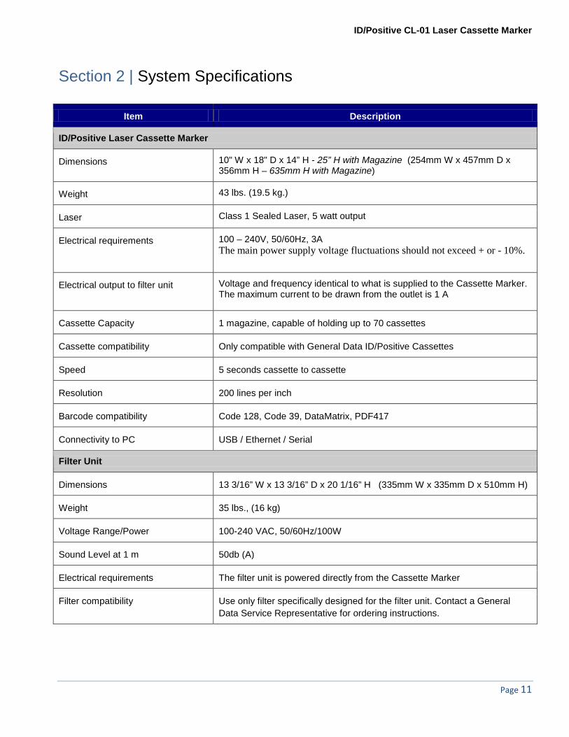
Section 2 | System Specifications
Item Description
ID/Positive Laser Cassette Marker
Dimensions 10" W x 18" D x 14” H - 25” H with Magazine (254mm W x 457mm D x 356mm H – 635mm H with Magazine)
Weight 43 lbs. (19.5 kg.)
Laser Class 1 Sealed Laser, 5 watt output
Electrical requirements 100 – 240V, 50/60Hz, 3A The main power supply voltage fluctuations should not exceed + or - 10%.
Electrical output to filter unit Voltage and frequency identical to what is supplied to the Cassette Marker. The maximum current to be drawn from the outlet is 1 A
Cassette Capacity 1 magazine, capable of holding up to 70 cassettes
Cassette compatibility Only compatible with General Data ID/Positive Cassettes
Speed 5 seconds cassette to cassette
Resolution 200 lines per inch
Barcode compatibility Code 128, Code 39, DataMatrix, PDF417
Connectivity to PC USB / Ethernet / Serial
Filter Unit
Dimensions 13 3/16” W x 13 3/16” D x 20 1/16” H (335mm W x 335mm D x 510mm H)
Weight 35 lbs., (16 kg)
Voltage Range/Power 100-240 VAC, 50/60Hz/100W
Sound Level at 1 m 50db (A)
Electrical requirements The filter unit is powered directly from the Cassette Marker
Filter compatibility Use only filter specifically designed for the filter unit. Contact a General Data Service Representative for ordering instructions.

Page 12
Section 3| LabeLase Producer CL®
Creating or changing the password Click on the File pull-down menu and select Supervisor.
The password screen will open. If creating a new password, click <OK>. If changing a password, enter the password and click <OK>.
ID/Positive CL-01 Laser Cassette Marker
Page 13
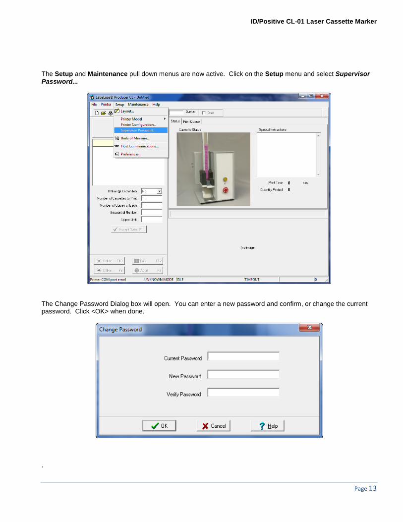
The Setup and Maintenance pull down menus are now active. Click on the Setup menu and select Supervisor Password...
The Change Password Dialog box will open. You can enter a new password and confirm, or change the current password. Click <OK> when done.
.
Page 14
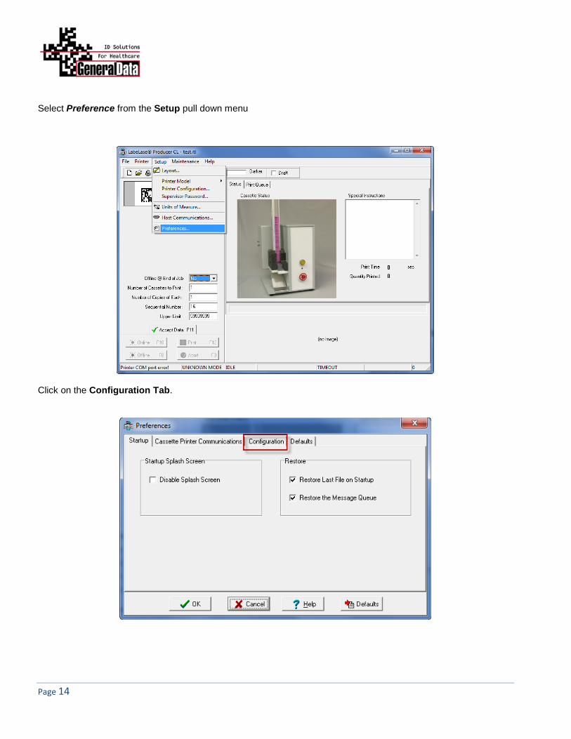
Select Preference from the Setup pull down menu
Click on the Configuration Tab.
ID/Positive CL-01 Laser Cassette Marker
Page 15
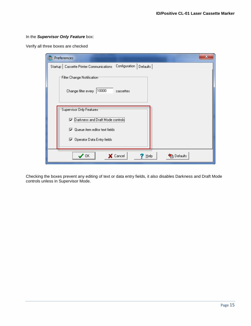
In the Supervisor Only Feature box: Verify all three boxes are checked
Checking the boxes prevent any editing of text or data entry fields, it also disables Darkness and Draft Mode controls unless in Supervisor Mode.
Page 16
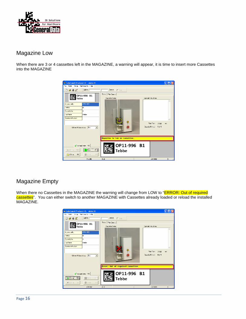
Magazine Low When there are 3 or 4 cassettes left in the MAGAZINE, a warning will appear, it is time to insert more Cassettes into the MAGAZINE
Magazine Empty When there no Cassettes in the MAGAZINE the warning will change from LOW to “ERROR: Out of required cassettes”. You can either switch to another MAGAZINE with Cassettes already loaded or reload the installed MAGAZINE.

ID/Positive CL-01 Laser Cassette Marker
Page 17
Deleteing a Job in the Queue Select a job in the queue you want to delete, click on <Delete> this will bring up a Confirm window. Click <Yes> to delete. NOTE: This will permanently remove the selected print job.
Deleting the entire Job Queue Click on <Clear> this will bring up a Confirm window. Click <Yes> to delete all print jobs in the queue. NOTE: This will permanently delete the entire job queue.

Page 18
Reprioritizing the Print Queue Select which print job you want to place at the top of the queue by clicking on that file. Then Click on <Move to Top> click <Yes> to Confirm. The print job has now print next. The remaining job queue will print in order.

ID/Positive CL-01 Laser Cassette Marker
Page 19
Section 4 | Operating the ID/Positive Laser Cassette Marker
The Cassette Marker comprises a laser enclosure with 1 cassette magazines capable of holding 70 tissue cassettes. Directly beneath the cassette magazine is the gripper mechanism which pushes cassettes from the magazine, transports them to the marking position and subsequently reverses them through the exit opening and down the cassette slide. The cassette magazine can be easily removed by simply lifting the magazine straight up to allow the user to change the cassette style or color. (Optional additional magazines are available for easy cassette style or color changes.) Located on the front panel are an Emergency Stop Button, Power Indicator (red LED) and an Online Button. The Online Button will illuminate when the Cassette Marker is online.
Main features of the CL-01 ID/Positive Laser Cassette Marker
Exit Chute
Cassette magazine
Online indicator and button
Power Indicator (red LED)
Emergency Stop Button
Page 20
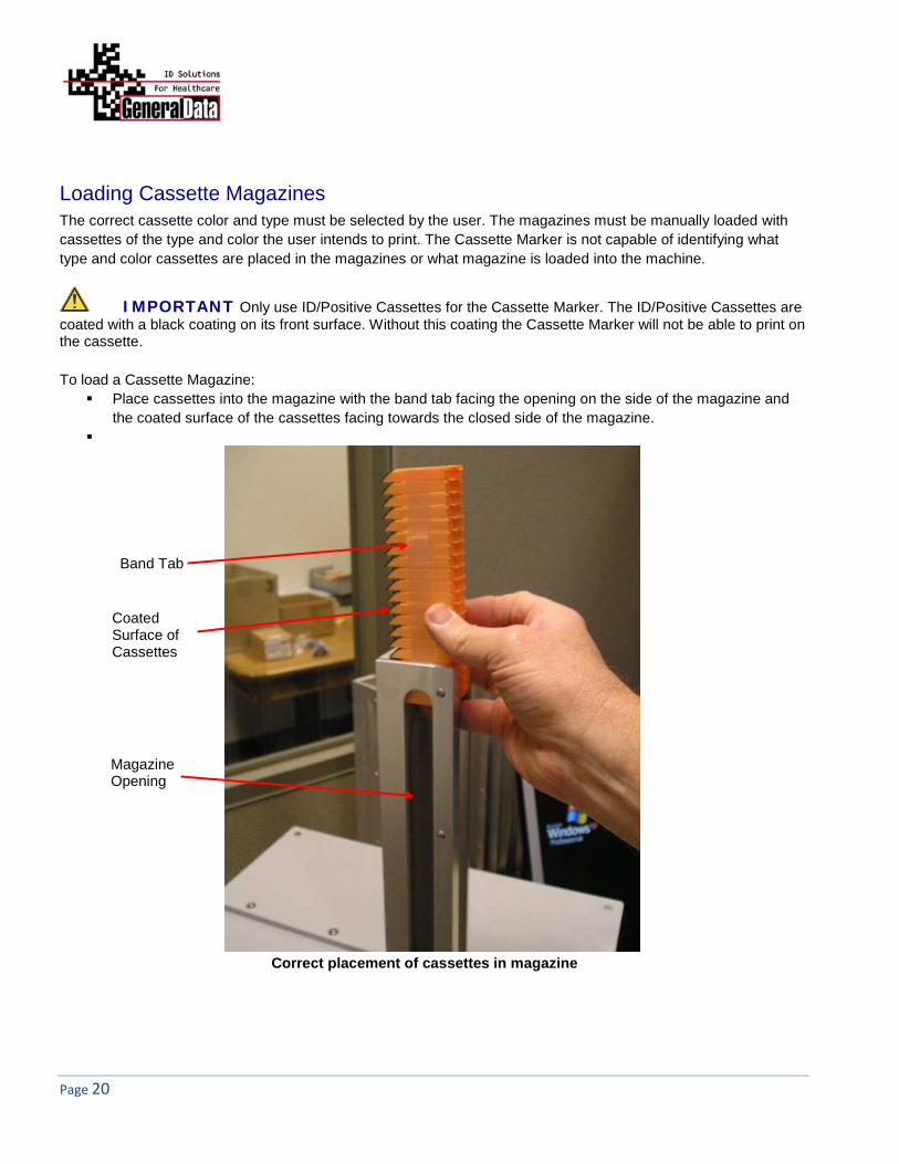
Loading Cassette Magazines The correct cassette color and type must be selected by the user. The magazines must be manually loaded with cassettes of the type and color the user intends to print. The Cassette Marker is not capable of identifying what type and color cassettes are placed in the magazines or what magazine is loaded into the machine.
IMPORTANT Only use ID/Positive Cassettes for the Cassette Marker. The ID/Positive Cassettes are coated with a black coating on its front surface. Without this coating the Cassette Marker will not be able to print on the cassette. To load a Cassette Magazine:
Place cassettes into the magazine with the band tab facing the opening on the side of the magazine and the coated surface of the cassettes facing towards the closed side of the magazine.
Correct placement of cassettes in magazine
Band Tab
Magazine Opening
Coated Surface of Cassettes

ID/Positive CL-01 Laser Cassette Marker
Page 21
Remove the banding while supporting the cassettes with a finger. Release cassettes once the band is removed.
Remove banding from cassettes through the magazine opening

Page 22
Safety Interlocks To prevent accidental exposure to harmful laser radiation the ID/Positive Laser Cassette Marker incorporates several types of safety features:
Mechanical Switches These switches are located on the front, rear and inside the main cover of the Cassette Marker. They will remove power supplied to the Cassette Marker. Switch A – Large Red, easily accessible, E-STOP operator Emergency Stop Push Button, located on the
front of the CL-01 Cassette Marker Switch B – Key switch, located on the rear of the Cassette Marker for lockout/tagout during service Switch C – On/Off Power rocker switch, located on the rear of the Cassette Marker Switch D – Safety Interlock, located inside the main cover
E-STOP
Key Switch
On/Off Power Rocker Switch
ID/Positive CL-01 Laser Cassette Marker
Page 23
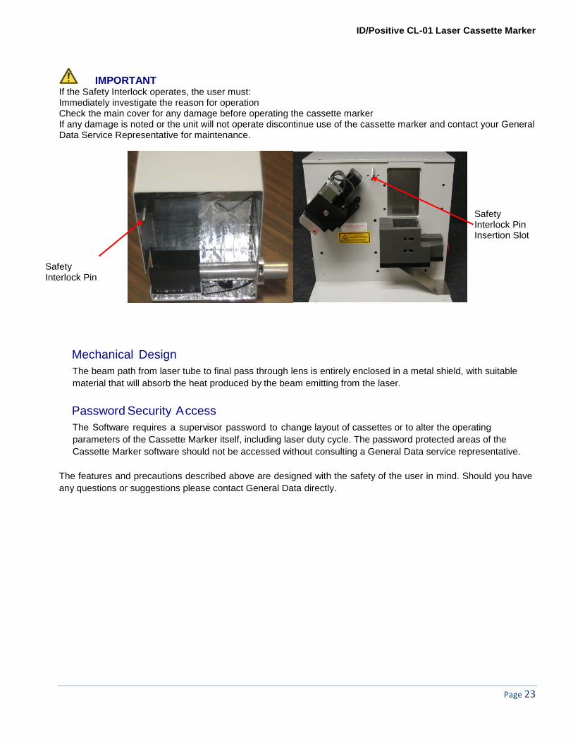
IMPORTANT If the Safety Interlock operates, the user must: Immediately investigate the reason for operation Check the main cover for any damage before operating the cassette marker If any damage is noted or the unit will not operate discontinue use of the cassette marker and contact your General Data Service Representative for maintenance.
Mechanical Design The beam path from laser tube to final pass through lens is entirely enclosed in a metal shield, with suitable material that will absorb the heat produced by the beam emitting from the laser.
Password Security Access The Software requires a supervisor password to change layout of cassettes or to alter the operating parameters of the Cassette Marker itself, including laser duty cycle. The password protected areas of the Cassette Marker software should not be accessed without consulting a General Data service representative.
The features and precautions described above are designed with the safety of the user in mind. Should you have any questions or suggestions please contact General Data directly.
Safety Interlock Pin
Safety Interlock Pin Insertion Slot

Page 24
Fuse Replacement Use the following procedure for fuse replacement:
IMPORTANT Remove power cord from Cassette Marker before replacing the fuse. 1. Remove fuse holder using small flat blade screwdriver. 2. Replace fuse with 5A, 250V fast acting fuse. 3. Reinsert fuse holder. 4. Reinsert the power cord.
Fuse Location
ID/Positive CL-01 Laser Cassette Marker
Page 25
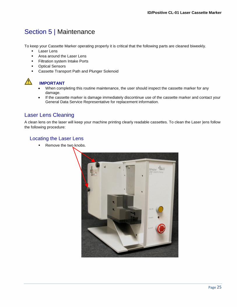
Section 5 | Maintenance
To keep your Cassette Marker operating properly it is critical that the following parts are cleaned biweekly. Laser Lens Area around the Laser Lens Filtration system Intake Ports Optical Sensors Cassette Transport Path and Plunger Solenoid
IMPORTANT • When completing this routine maintenance, the user should inspect the cassette marker for any
damage. • If the cassette marker is damage immediately discontinue use of the cassette marker and contact your
General Data Service Representative for replacement information.
Laser Lens Cleaning A clean lens on the laser will keep your machine printing clearly readable cassettes. To clean the Laser |ens follow the following procedure:
Locating the Laser Lens Remove the two knobs.
Page 26
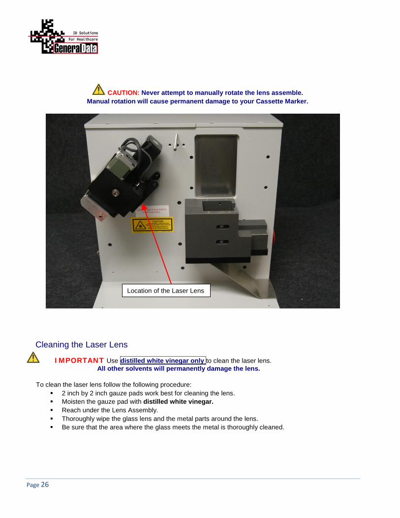
CAUTION: Never attempt to manually rotate the lens assemble. Manual rotation will cause permanent damage to your Cassette Marker.
Cleaning the Laser Lens
IMPORTANT Use distilled white vinegar only to clean the laser lens. All other solvents will permanently damage the lens.
To clean the laser lens follow the following procedure:
2 inch by 2 inch gauze pads work best for cleaning the lens. Moisten the gauze pad with distilled white vinegar. Reach under the Lens Assembly. Thoroughly wipe the glass lens and the metal parts around the lens. Be sure that the area where the glass meets the metal is thoroughly cleaned.
Location of the Laser Lens

ID/Positive CL-01 Laser Cassette Marker
Page 27
The above photo is a close up of the Laser Lens.

Page 28
Cleaning the Filtration Intake Tubes The Cassette Marker filtration system needs to be cleaned biweekly to keep it operating properly.
The silver Intake Tube is located inside the Main Cover
Cleaning the Intake Tube The silver intake tube can collect dust if it is not cleaned biweekly.
Use a 2 inch by 2 inch gauze pad to clean the Intake Tube and the area around the tube. First wipe the area with a dry gauze pad Then use a gauze pad moistened with distilled white vinegar to thoroughly clean the Intake Tube
and the area around the tube.
ID/Positive CL-01 Laser Cassette Marker
Page 29
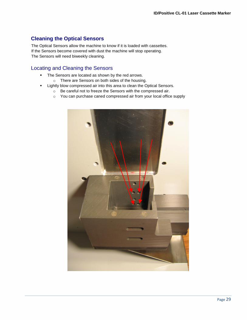
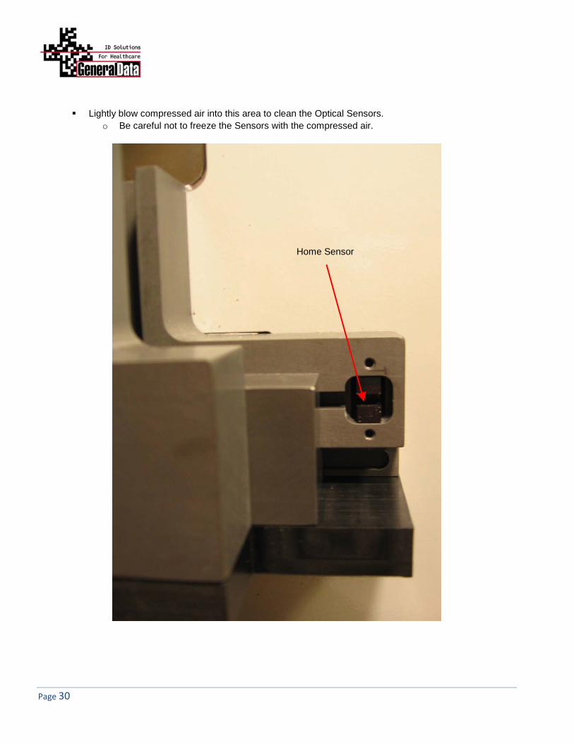
Cleaning the Optical Sensors The Optical Sensors allow the machine to know if it is loaded with cassettes. If the Sensors become covered with dust the machine will stop operating. The Sensors will need biweekly cleaning.
Locating and Cleaning the Sensors The Sensors are located as shown by the red arrows.
o There are Sensors on both sides of the housing. Lightly blow compressed air into this area to clean the Optical Sensors.
o Be careful not to freeze the Sensors with the compressed air. o You can purchase caned compressed air from your local office supply
Page 30
Lightly blow compressed air into this area to clean the Optical Sensors. o Be careful not to freeze the Sensors with the compressed air.
Home Sensor

ID/Positive CL-01 Laser Cassette Marker
Page 31
CAUTION: Always use a dry gauze to clean the main laser assembly. Allowing liquid to drip into the motor or other electrical parts will cause permanent damage to your cassette marker.
Use a DRY gauze to thoroughly clean the area around the main laser assembly. Lightly blow compressed air into this area to clean the Optical Sensors.
o Be careful not to freeze the Sensors with the compressed air.
Cleaning the Cassette Transport Path and Solenoid Plunger • A buildup of tape adhesive from the Cassette Packs may cause a problem with Cassettes not properly
ejecting. Cleaning the Solenoid Plunger and Slide Guide will keep the area clear of any adhesive.
Page 32
Filter Replacement Filters in the Filtration System must be changed periodically to ensure safe and reliable operation of your ID/Positive Laser Cassette Marker.
• The filter unit contains two filters; the pre-filter and the main filter.
IMPORTANT Use only pre-filter bags and main filter cartridges recommended by General Data. Other filters may hamper the airflow in the filter unit, or may not be able to remove all dust particles from the exhaust. Contact a General Data representative for further information
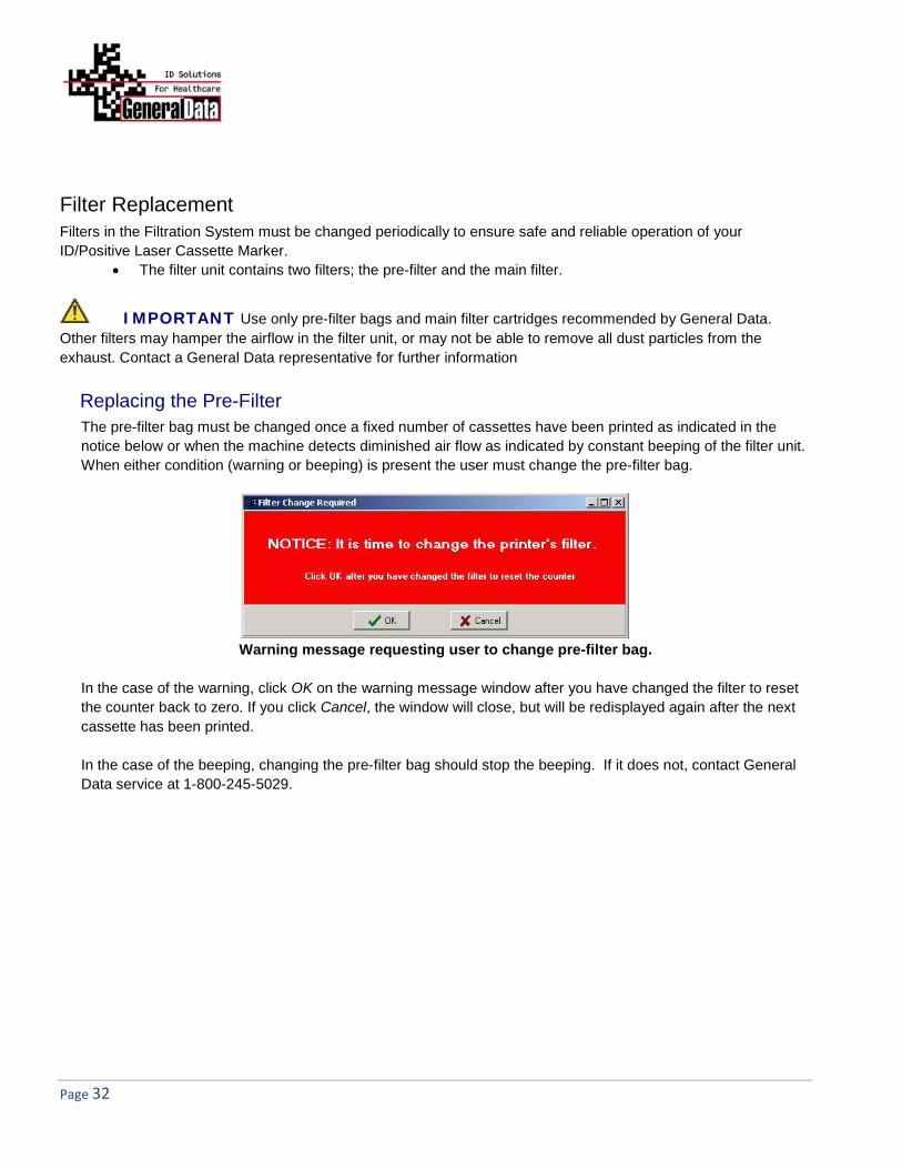
Replacing the Pre-Filter The pre-filter bag must be changed once a fixed number of cassettes have been printed as indicated in the notice below or when the machine detects diminished air flow as indicated by constant beeping of the filter unit. When either condition (warning or beeping) is present the user must change the pre-filter bag.
Warning message requesting user to change pre-filter bag.
In the case of the warning, click OK on the warning message window after you have changed the filter to reset the counter back to zero. If you click Cancel, the window will close, but will be redisplayed again after the next cassette has been printed. In the case of the beeping, changing the pre-filter bag should stop the beeping. If it does not, contact General Data service at 1-800-245-5029.
ID/Positive CL-01 Laser Cassette Marker
Page 33
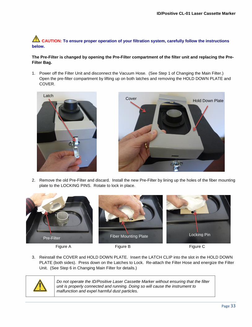
CAUTION: To ensure proper operation of your filtration system, carefully follow the instructions below. The Pre-Filter is changed by opening the Pre-Filter compartment of the filter unit and replacing the Pre-Filter Bag.
1. Power off the Filter Unit and disconnect the Vacuum Hose. (See Step 1 of Changing the Main Filter.)
Open the pre-filter compartment by lifting up on both latches and removing the HOLD DOWN PLATE and COVER.
2. Remove the old Pre-Filter and discard. Install the new Pre-Filter by lining up the holes of the fiber mounting plate to the LOCKING PINS. Rotate to lock in place.
Figure A Figure B Figure C
3. Reinstall the COVER and HOLD DOWN PLATE. Insert the LATCH CLIP into the slot in the HOLD DOWN
PLATE (both sides). Press down on the Latches to Lock. Re-attach the Filter Hose and energize the Filter Unit. (See Step 6 in Changing Main Filter for details.)
Do not operate the ID/Positive Laser Cassette Marker without ensuring that the filter unit is properly connected and running. Doing so will cause the instrument to malfunction and expel harmful dust particles.
Latch Cover Hold Down Plate
Pre-Filter Fiber Mounting Plate Locking Pin
Page 34
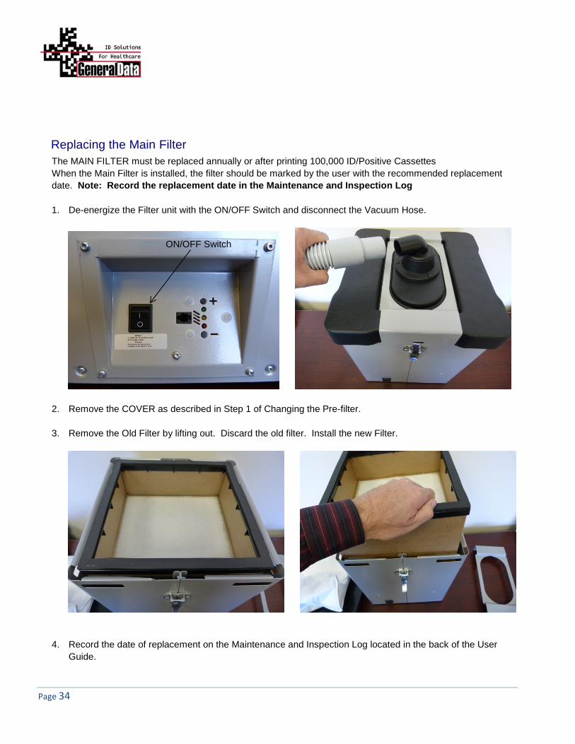
Replacing the Main Filter The MAIN FILTER must be replaced annually or after printing 100,000 ID/Positive Cassettes When the Main Filter is installed, the filter should be marked by the user with the recommended replacement date. Note: Record the replacement date in the Maintenance and Inspection Log 1. De-energize the Filter unit with the ON/OFF Switch and disconnect the Vacuum Hose.
2. Remove the COVER as described in Step 1 of Changing the Pre-filter. 3. Remove the Old Filter by lifting out. Discard the old filter. Install the new Filter.
4. Record the date of replacement on the Maintenance and Inspection Log located in the back of the User Guide.
ON/OFF Switch

ID/Positive CL-01 Laser Cassette Marker
Page 35
5. Re-install the COVER and HOLD DOWN PLATE and lock the COVER down with the Latch
6. Reconnect the 90° Elbow and Vacuum Hose.
7. Energize the Filter Unit. Test by printing a cassette. There should be no air leaks and the Filter Unit should
power down approximately 2½ minutes after the cassette has printed.
90° Elbow Vacuum Hose

Page 36
Troubleshooting the Main Filter Unit 1. If the Filter Unit does not energize, check:
a. The Power Cable on the Filter and Cassette Marker are connected b. Check the Fuse in the Power Inlet. (See Figure 1) c. Plug the unit into a wall outlet, a computer power cable will be necessary for this
i. If the unit energizes, the problem is in the Cassette Marker. Call General Data Service ii. If the unit does not energize, the problem is in the Filter unit. Call General Data for service
2. An Alarm sounds three seconds after the unit is energized
a. Recommended Filter life has been exceeded, replace the Main Filter. The Filter Unit will continue to operate, this is just an alarm.
b. Call General Data Service (800-245-5029)
3. Three Beep Alarm, RED LED on the panel flashes a. Suction capacity is low – The unit will stop in 5 minutes if service is not provided. b. Look for any obstructions in the Vacuum hoses. c. Check and clean hoses, replace the Pre-Filter.
Figure 1
Fuse
ID/Positive CL-01 Laser Cassette Marker
Page 37
Appendix A | Backing up Printer Configuration and Layout Format Files
On occasion the Client PC has a failure on the hard drive. This creates a problem because the files used for printing the barcode may be lost. Also if the printer configuration files get corrupted, this will cause additional printing problems. Therefore is highly recommended that backing up the Printer Configuration and Layout Format files be done at installation. The following procedure will step you through creating Printer Configuration and Layout Format backup files:
Exporting Printer Configuration Files
1. Create a folder on a network drive or external device to copy the Printer Configuration file and Layout Formats. For example create a folder named CL-12 4034. CL-12 for the 12 color marker and 4034 for the last 4 digits of the serial number.
a. Create a sub folder within the CL-12 folder for the Info Tag Layout files (.itl files). As an example, name the subfolder “Format Files”. Drag and drop the Info Tag Layout files into the sub-folder.
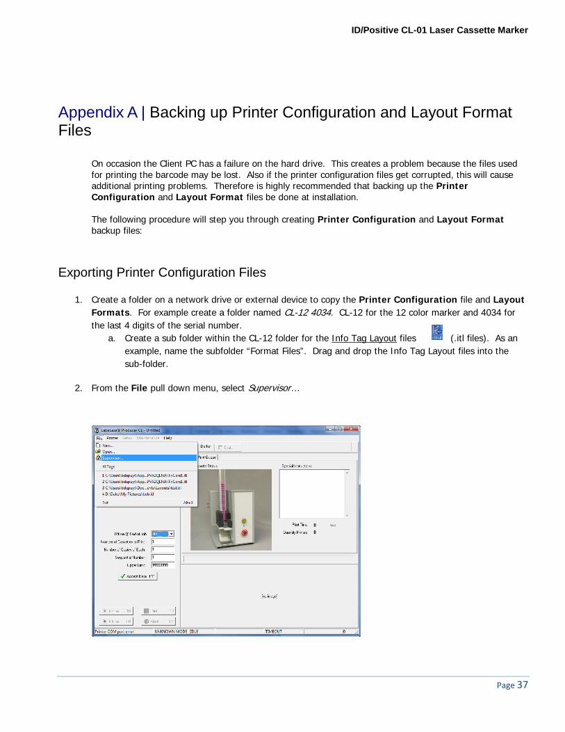
2. From the File pull down menu, select Supervisor…

Page 38
3. Enter the password if one is required, click <OK>
4. From the Setup pull down menu, select Printer configuration…
ID/Positive CL-01 Laser Cassette Marker
Page 39
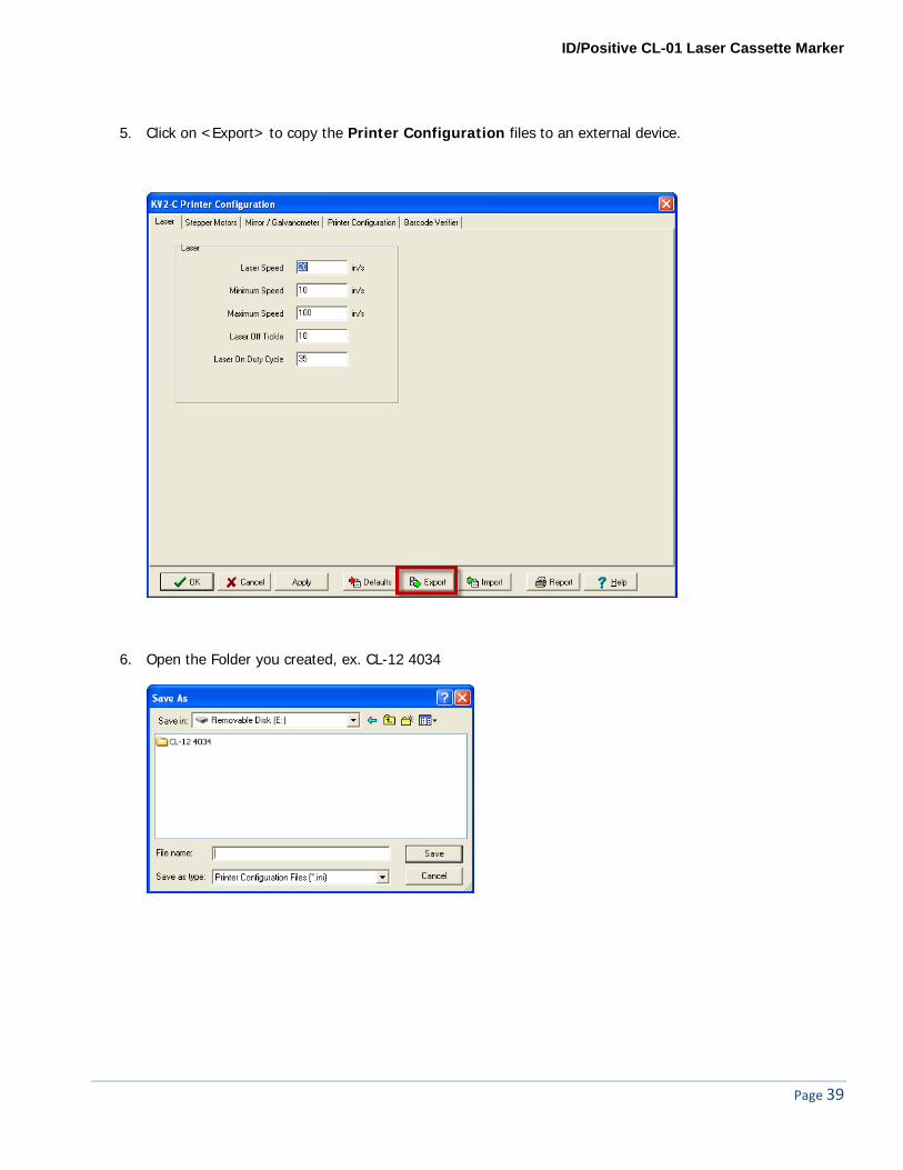
5. Click on <Export> to copy the Printer Configuration files to an external device.
6. Open the Folder you created, ex. CL-12 4034
Page 40
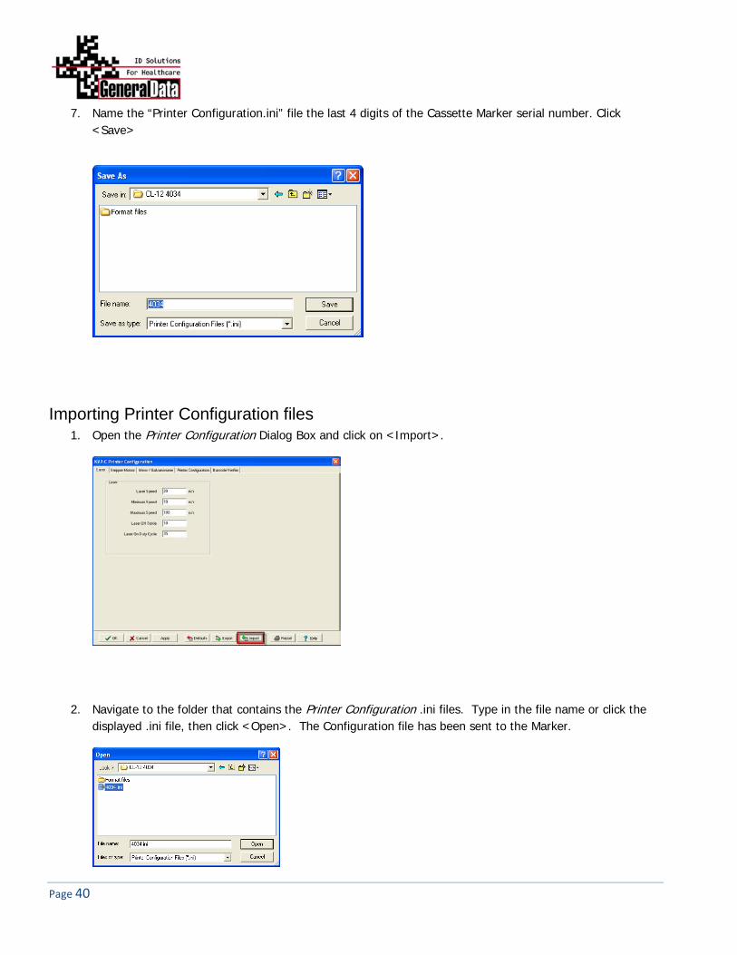
7. Name the “Printer Configuration.ini” file the last 4 digits of the Cassette Marker serial number. Click <Save>
Importing Printer Configuration files 1. Open the Printer Configuration Dialog Box and click on <Import>.
2. Navigate to the folder that contains the Printer Configuration .ini files. Type in the file name or click the displayed .ini file, then click <Open>. The Configuration file has been sent to the Marker.
ID/Positive CL-01 Laser Cassette Marker
Page 41
Appendix B | Laser Safety
Laser Hazard Classifications The intent of laser hazard classification is to provide clear distinction of the lasers’ properties and hazards to users so appropriate protective measures can be taken. Classification is based on the maximum output available for the intended use. Specific labeling requirements indicate that the class of the laser as well as the emission wavelength(s) and any other applicable precautionary instructions must be included on any signage. Laser classification is also used for determining requirements for medical surveillance for those individuals working with and around lasers. The Federal United States laser safety standard [21 CFR 1040.10], the ANSI standard [ANSI Z136.1], as well as the international standard [EN 60825], divide lasers into five distinct hazard categories. These classes are based upon the combination of wavelength range, power, and emission duration, which are used to determine the level of risk and the potential to cause biological damage to the eye or skin. The definitions compiled from ANSI Z136.1 are as follows: The General Data ID/Positive Laser Cassette Marker, Model CL-01 is rated as follows:
CLASS 1 LASER PRODUCT, USING A CLASS 4 EMBEDDED LASER (5 W, 10.57 – 10.63 μm)
Class 1: Any laser, or laser system containing a laser, with wavelength ranges from Ultraviolet through Far Infrared (180 nm – 100,000 nm +), that cannot emit laser radiation levels exceeding Class 1 Accessible Emission Limits (AEL) as defined by ANSI Z136.1. For example this would compute to exposure (for an eight-hour period) for a 488 nm laser of no greater than 0.2 mW. Basically, the laser radiation level emitted by a device classified as Class 1 produces no hazard whatsoever to the user during normal operation. Presently, Class 1 lasers and laser systems are exempt from all control measures. The Class 1 designation does not apply during times of maintenance or service where the safety controls of the device are defeated or otherwise removed. The Class 1 environment resumes once the device is returned to its original state with all safety devices properly reconnected. Class 2: This classification applies only to continuous wave (CW) and repetitive-pulse lasers and laser systems of the visible part of the electromagnetic spectrum (400 – 700 nm) that exceed Class 1 levels, but do not exceed an average radiant power of 1 mW. Class 3a: Lasers and laser systems that have an accessible output between one and five times the Class 1 AEL for wavelengths shorter than 400 nm or longer than 700 nm, or less than five times the Class 2 AEL for wavelengths between 400 and 700 nm. Lasers of this class have intermediate power ranges of 1 - 5 mW. Class 3b: Lasers and laser systems having the power range between 5 - 500 mW. This applies to lasers with wavelength ranges from Ultraviolet through Far Infrared (180 nm – 100,000 nm +). These lasers or laser systems can produce a hazard if viewed directly, and may produce an eye hazard when viewing diffuse reflections off of a shiny surface at angles of less than 5 degrees from the source, however Class 3b lasers should not produce a hazardous diffuse reflection from a matte (not shiny) surface. Class 4: Lasers and laser systems having power greater than 500 mW. This applies to lasers with wavelength ranges from Ultraviolet through Far Infrared (180 nm – 100,000 nm +). This class of laser poses the greatest
Page 42
hazard, and any and all precautions should be taken to protect oneself from exposure to direct or diffuse laser radiation. Direct exposure to the eye from this class of laser can cause permanent damage. Stray beams are potential fire hazards and combustible material should be kept out of beam paths at all times.
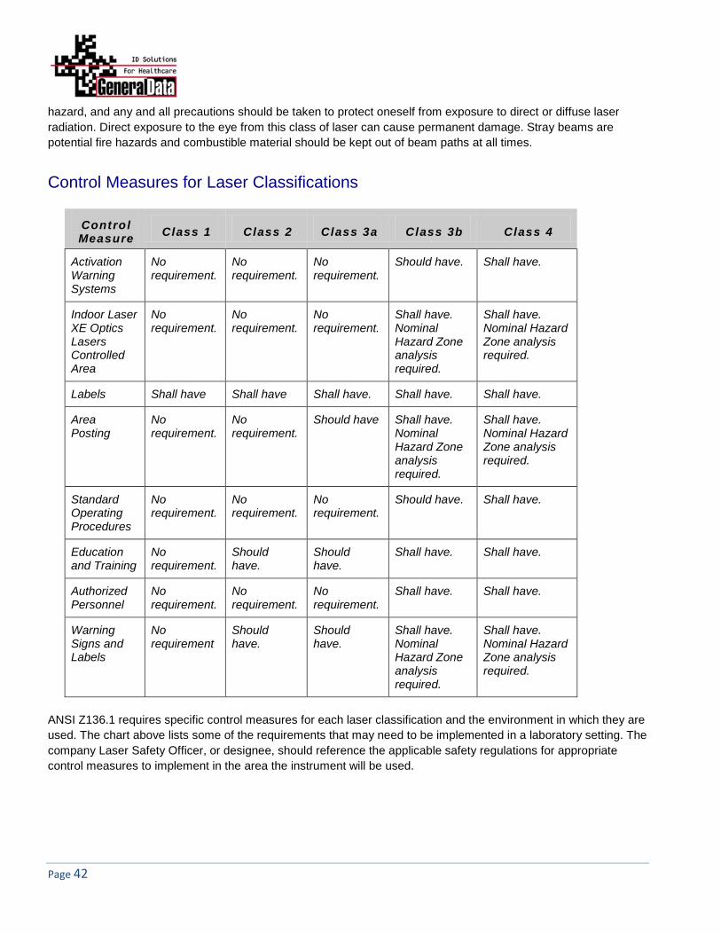
Control Measures for Laser Classifications
Control Measure Class 1 Class 2 Class 3a Class 3b Class 4
Activation Warning Systems
No requirement.
No requirement.
No requirement.
Should have. Shall have.
Indoor Laser XE Optics Lasers Controlled Area
No requirement.
No requirement.
No requirement.
Shall have. Nominal Hazard Zone analysis required.
Shall have. Nominal Hazard Zone analysis required.
Labels Shall have Shall have Shall have. Shall have. Shall have.
Area Posting
No requirement.
No requirement.
Should have Shall have. Nominal Hazard Zone analysis required.
Shall have. Nominal Hazard Zone analysis required.
Standard Operating Procedures
No requirement.
No requirement.
No requirement.
Should have. Shall have.
Education and Training
No requirement.
Should have.
Should have.
Shall have. Shall have.
Authorized Personnel
No requirement.
No requirement.
No requirement.
Shall have. Shall have.
Warning Signs and Labels
No requirement
Should have.
Should have.
Shall have. Nominal Hazard Zone analysis required.
Shall have. Nominal Hazard Zone analysis required.
ANSI Z136.1 requires specific control measures for each laser classification and the environment in which they are used. The chart above lists some of the requirements that may need to be implemented in a laboratory setting. The company Laser Safety Officer, or designee, should reference the applicable safety regulations for appropriate control measures to implement in the area the instrument will be used.

ID/Positive CL-01 Laser Cassette Marker
Page 43
Biological Effects of Laser Irradiation
Eye Injury Because of the high degree of beam collimation, a laser serves as an almost ideal point source of intense light. A laser beam of sufficient power can theoretically produce retinal intensities at magnitudes that are greater than conventional light sources, and even larger than those produced when directly viewing the sun. Eye exposure to a direct beam can cause permanent eye damage including blindness. Protective eyewear should always be worn when potential exposure to direct laser beams exist.
Due to the lens-like focusing effect of the human eye, it is 100,000 times more vulnerable to injury than the skin.
Laser safety eyewear should always be available for the wavelengths of lasers in use. Eye protective equipment, however, should be considered the last line of defense against laser beam
exposure – engineering and administrative controls should be used first. Remove all jewelry when working with an open beam to prevent reflection of the beam in unsafe
directions. When possible, use all protective housings, interlocks and shields. Laser Safety Eyewear should always be worn during laser repair, alignment, or installation, or at any time
when any laser safety control is not in place.
Thermal Injury The most common cause of laser-induced tissue damage is thermal in nature, where the tissue proteins are denatured due to the temperature rise following absorption of laser energy. The thermal damage process (resulting in burns) is generally associated with lasers operating at exposure times greater than 10 microseconds and in the wavelength region from the near ultraviolet to the far infrared. Tissue damage may also be caused by thermally induced acoustic waves following exposures to sub-microsecond laser exposures.
Skin Injury To the skin, UVA (315-400 nm) can cause hyperpigmentation and erythema (aka: sunburn). Exposure in the UVB (280-315 nm) range is most injurious to skin. In addition to thermal injury caused by ultraviolet energy, there is also possibility of radiation carcinogenesis from UVB. The shorter wavelengths are absorbed in the outer dead layers of the epidermis (stratum corneum) and the longer wavelengths have an initial pigment-darkening effect followed by erythema if there is exposure to excessive levels. The hazards associated with skin exposure are of less importance than eye hazards; however, with the expanding use of higher-power laser systems, particularly ultraviolet lasers, the unprotected skin of personnel may be exposed to extremely hazardous levels of the beam power if used in an unenclosed system design. Skin burns caused by lasers can happen quite fast and with great intensity. Protective clothing should be worn when potential exposure to direct laser beams exist.
UVC: 200-280 nm exposure may cause erythema (sunburn), skin cancer, and burns. UVB: 280-315 nm exposure may cause accelerated skin aging, increased skin pigmentation and burns. UVA: 315-400 nm exposure may cause pigment darkening and skin burns. Visible: 400-700 nm exposure may cause photosensitive reactions and skin burns. Infrared 700-100,000 nm exposure may cause skin burns.

Page 44
Appendix C | Symbol Definitions
Instrument Serial Number
ID/Positive Model Number
Date of Manufacture
Alternating Current Input
Caution, Consult Accompanying Documents
Caution, Laser Radiation - Consult Accompanying Documents
Warning label located above the rating plate on the back of the ID/Positive Laser Cassette Marker:
CLASS 1 LASER PRODUCT
Warning label located on the inside the main access cover:
CLASS 4 INVISIBLE LASER RADIATION WHEN OPEN AND INTERLOCKS DEFEATED AVOID EYE OR SKIN EXPOSURE TO DIRECT OR SCATTERED RADIATION

ID/Positive CL-01 Laser Cassette Marker
Page 45
Identification of Manufacturer
Correct Disposal of this Product (According to Directive 2002/96/EC on Waste Electrical and Electronic Equipment [WEEE] applicable in the European Union and other European countries with separate collection systems). Contact a General Data representative for disposal of the equipment at the end of its working life. This product should not be mixed with other commercial waste for disposal.
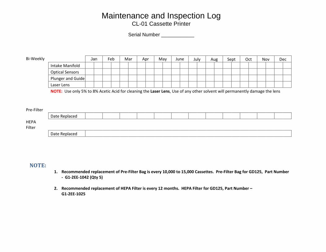
Maintenance and Inspection Log CL-01 Cassette Printer
Serial Number ____________
Bi-Weekly
Jan Feb Mar Apr May June July Aug Sept Oct Nov Dec Intake Manifold Optical Sensors
Plunger and Guide
Laser Lens
NOTE: Use only 5% to 8% Acetic Acid for cleaning the Laser Lens, Use of any other solvent will permanently damage the lens
Pre-Filter
Date Replaced
HEPA Filter
Date Replaced
NOTE:
1. Recommended replacement of Pre-Filter Bag is every 10,000 to 15,000 Cassettes. Pre-Filter Bag for GD125, Part Number - G1-2EE-1042 (Qty 5)
2. Recommended replacement of HEPA Filter is every 12 months. HEPA Filter for GD125, Part Number –
G1-2EE-1025