Embed Size (px)
Citation preview

P11-710-6
All leaflets are available on: www.ascojoucomatic.com
1
Modulair 107343 04 001
Modulair 112343 03 001
Modulair 107 or 112 range components can easily be assembled with an assembly kit accessible from the front. AllModulair products of the same range can be combined as desired.
Modulair 107 and 112 ranges
GENERAL DESCRIPTION
PRINCIPAL ADVANTAGES
● ● ● ● ● Compact Product
● ● ● ● ● Time saving in installation (2 side mounting brackets)
=
Assembly of components
Modulair 105 range

P11-710-7
All leaflets are available on: www.ascojoucomatic.com
1107
Mounting screws not supplied Mounting screws not supplied
GENERAL DESCRIPTION
Side mounting bracketswith Modulair 107-112
Direct frontal mountingwith Modulair 107-112
●
A
B
C
D
DA
C
●
B
21
90˚
Modulair 107 Modulair 112
Side mounting bracketswith Modulair 105
Modulair 105343 25 005
Adjustment of regulator orfilter/regulator (all models)
Adjustment and refilling of lubricatorwith Modulair 107 and 112 ranges
ON REGULATOR OR FILTER/REGULATORby key lock of downstream pressure adjustment
with Modulair 107 and 112 ranges(same model for all three ranges)
ON PAD-LOCKABLEISOLATION VALVE
with Modulair 107-112 ranges
Locking devices
Lockable oil flow adjustment
Oil flow adjustable with screw driver or hex key
360° oil flow sight glass.In-service lubricator refilling capability:Modulair 107 (on request), Modulair 112
Oil filler cap
Modulair 107343 04 003
Modulair 112343 03 003
P11-710-8
All leaflets are available on: www.ascojoucomatic.com
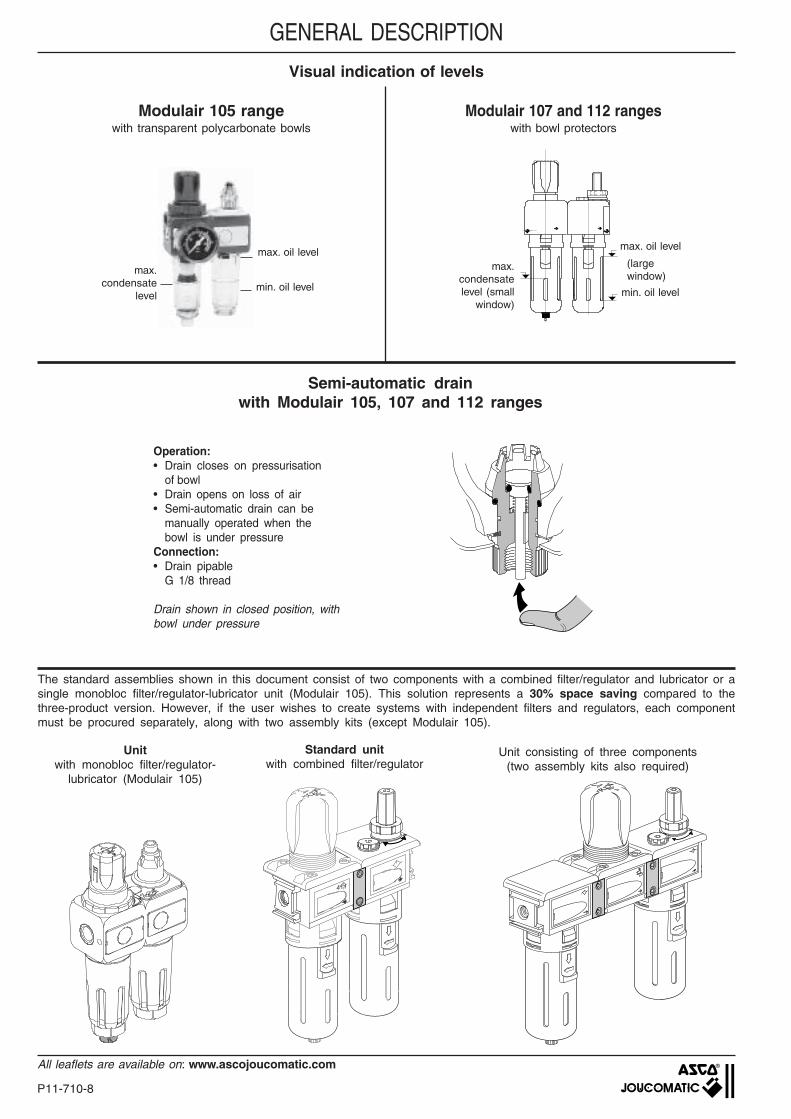
The standard assemblies shown in this document consist of two components with a combined filter/regulator and lubricator or asingle monobloc filter/regulator-lubricator unit (Modulair 105). This solution represents a 30% space saving compared to thethree-product version. However, if the user wishes to create systems with independent filters and regulators, each componentmust be procured separately, along with two assembly kits (except Modulair 105).
Unit consisting of three components(two assembly kits also required)
Standard unitwith combined filter/regulator
max. oil level
Operation:• Drain closes on pressurisation
of bowl• Drain opens on loss of air• Semi-automatic drain can be
manually operated when thebowl is under pressure
Connection:• Drain pipable
G 1/8 thread
Drain shown in closed position, withbowl under pressure
min. oil level
max.condensate
level
Semi-automatic drainwith Modulair 105, 107 and 112 ranges
Modulair 105 rangewith transparent polycarbonate bowls
Modulair 107 and 112 rangeswith bowl protectors
Visual indication of levels
GENERAL DESCRIPTION
max. oil levelmax.
condensatelevel (small
window)min. oil level
(largewindow)
Unitwith monobloc filter/regulator-
lubricator (Modulair 105)
P11-710-9
All leaflets are available on: www.ascojoucomatic.com
1107
OVERALL SPECIFICATIONFLUID : Compressed air or neutral gasRANGEPORTSMAX. INLET PRESSURE (bar) at 23°C
at 50°CCONTROLLED PRESSURE (bar)AMBIENT TEMPERATURE (°C)MAX. FLOW (Qv at 6.3 bar)REGULATORLUBRICATION
(l/min) (dm3/s) (l/min) (dm3/s)(cm3) (µm) (bar)
G1/8 105 28 25 0,5-8 20 0,3 400 6,7 40 342 25 183 342 25 181 - -G1/4 105 28 25 0,5-8 20 0,3 550 9,2 40 342 25 184 342 25 182 - -
G1/8 107 50 25 0,5-10 20 0,3 700 11,7 40 342 04 131 342 04 127 - -G1/4 107 50 25 0,5-10 20 0,3 1300 22 40 342 04 132 342 04 128 - -G1/4 112 114 25 0,5-10 20 0,3 1800 30 50 342 03 290 342 03 302 342 03 396 342 03 393G3/8 112 114 25 0,5-10 20 0,3 3000 50 50 342 03 291 342 03 303 342 03 397 342 03 394G1/2 112 114 25 0,5-10 20 0,3 3000 50 50 342 03 292 342 03 304 342 03 398 342 03 395
G1/8 105 28 25 0,5-8 20 0,3 400 6,7 40 342 25 103 342 25 101 - -G1/4 105 28 25 0,5-8 20 0,3 550 9,2 40 342 25 104 342 25 102 - -G1/8 107 50 25 0,5-10 20 0,3 700 11,7 40 342 04 137 342 04 133 - -G1/4 107 50 25 0,5-10 20 0,3 1300 22 40 342 04 138 342 04 134 - -G1/4 112 114 25 0,5-10 20 0,3 1800 30 50 342 03 314 342 03 326 342 03 402 342 03 399G3/8 112 114 25 0,5-10 20 0,3 3000 50 50 342 03 315 342 03 327 342 03 403 342 03 400G1/2 112 114 25 0,5-10 20 0,3 3000 50 50 342 03 316 342 03 328 342 03 404 342 03 401
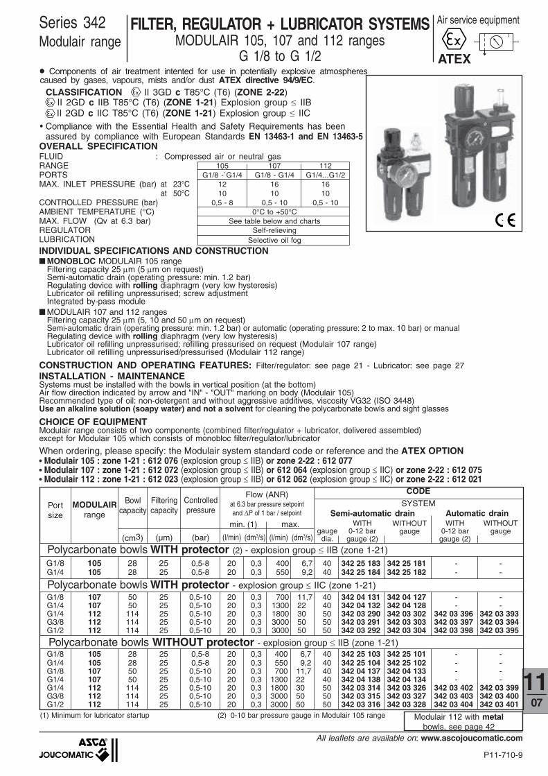
FILTER, REGULATOR + LUBRICATOR SYSTEMSMODULAIR 105, 107 and 112 ranges
G 1/8 to G 1/2
Series 342Modulair range
Air service equipment
INDIVIDUAL SPECIFICATIONS AND CONSTRUCTION■ MONOBLOC MODULAIR 105 range
Filtering capacity 25 µm (5 µm on request)Semi-automatic drain (operating pressure: min. 1.2 bar)Regulating device with rolling diaphragm (very low hysteresis)Lubricator oil refilling unpressurised; screw adjustmentIntegrated by-pass module
■ MODULAIR 107 and 112 rangesFiltering capacity 25 µm (5, 10 and 50 µm on request)Semi-automatic drain (operating pressure: min. 1.2 bar) or automatic (operating pressure: 2 to max. 10 bar) or manualRegulating device with rolling diaphragm (very low hysteresis)Lubricator oil refilling unpressurised; refilling pressurised on request (Modulair 107 range)Lubricator oil refilling unpressurised/pressurised (Modulair 112 range)
CONSTRUCTION AND OPERATING FEATURES: Filter/regulator: see page 21 - Lubricator: see page 27INSTALLATION - MAINTENANCESystems must be installed with the bowls in vertical position (at the bottom)Air flow direction indicated by arrow and "IN" - "OUT" marking on body (Modulair 105)Recommended type of oil: non-detergent and without aggressive additives, viscosity VG32 (ISO 3448)Use an alkaline solution (soapy water) and not a solvent for cleaning the polycarbonate bowls and sight glasses
CHOICE OF EQUIPMENTModulair range consists of two components (combined filter/regulator + lubricator, delivered assembled)except for Modulair 105 which consists of monobloc filter/regulator/lubricator
gaugedia.
WITH0-12 bargauge (2)
WITHOUTgauge
WITH0-12 bar
gauge (2)
Semi-automatic drain Automatic drain
CODE
SYSTEM
min. (1) max.
Flow (ANR)at 6.3 bar pressure setpointand ∆P of 1 bar / setpoint
MODULAIRrange
Polycarbonate bowls WITH protector (2) - explosion group ≤ IIB (zone 1-21)
(1) Minimum for lubricator startup (2) 0-10 bar pressure gauge in Modulair 105 range
WITHOUTgauge
Polycarbonate bowls WITHOUT protector - explosion group ≤ IIB (zone 1-21)
Portsize
Bowlcapacity
Filteringcapacity
Controlledpressure
Modulair 112 with metalbowls, see page 42
When ordering, please specify: the Modulair system standard code or reference and the ATEX OPTION• Modulair 105 : zone 1-21 : 612 076 (explosion group ≤ IIB) or zone 2-22 : 612 077• Modulair 107 : zone 1-21 : 612 072 (explosion group ≤ IIB) or 612 064 (explosion group ≤ IIC) or zone 2-22 : 612 075• Modulair 112 : zone 1-21 : 612 023 (explosion group ≤ IIB) or 612 062 (explosion group ≤ IIC) or zone 2-22 : 612 021
ATEX●●●●● Components of air treatment intented for use in potentially explosive atmospherescaused by gases, vapours, mists and/or dust ATEX directive 94/9/EC.
CLASSIFICATION II 3GD c T85°C (T6) (ZONE 2-22) II 2GD c IIB T85°C (T6) (ZONE 1-21) Explosion group ≤ IIB II 2GD c IIC T85°C (T6) (ZONE 1-21) Explosion group ≤ IIC
• Compliance with the Essential Health and Safety Requirements has beenassured by compliance with European Standards EN 13463-1 and EN 13463-5
105 107 112G1/8 -`G1/4 G1/8 - G1/4 G1/4...G1/2
12 16 1610 10 10
0,5 - 8 0,5 - 10 0,5 - 100°C to +50°C
See table below and chartsSelf-relieving
Selective oil fog
Polycarbonate bowls WITH protector - explosion group ≤ IIC (zone 1-21)
P11-710-10
All leaflets are available on: www.ascojoucomatic.com
CODES
Side mounting brackets 343 25 005 343 04 003 343 03 003Top mounting ring 343 00 011 343 00 011 -Top mounting bracket 343 00 016 343 00 016 (1)40 mm dia. pressure gauge (0-10 bar) 343 00 014 - -40 mm dia. pressure gauge (0-12 bar) - 343 00 041 -50 mm dia. pressure gauge (0-12 bar) - - 342 00 062Two-part assembly kit - 343 04 001 343 03 001
Modulair 105 Modulair 107 Modulair 112
(A)
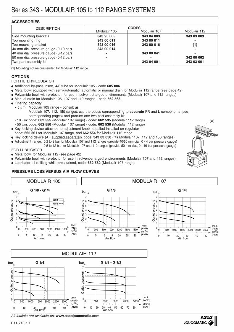
MODULAIR 105 MODULAIR 107
0 500 1000 1500 2000 2500 30000
1
2
3
4
5
7
6
0 10 20 30 40 50
l/min (ANR)dm3/s(ANR)
bar
MODULAIR 112
G 1/4
0 300 600 900 1200 1500 18000
1
2
3
4
5
7
6
0 5 10 15 20 25 30
l/min (ANR)dm3/s(ANR)
bar
G1/4G1/8
G 1/8 - G1/4
0 300 600 900 1200 1500 18000
1
2
3
4
5
7
6
0 5 10 15 20 25 30
l/min (ANR)dm3/s(ANR)
bar G 1/8
G 1/4
0 500 1000 1500 2000 2500 30000
1
2
3
4
5
6
7
0 10 20 30 40 500
bar
l/min (ANR)
dm3/s(ANR)
Out
let
pres
sure
G 3/8 - G 1/2
0 10 20 30 40 50 60 70 800
1
1
2
3
4
5
6
7
bar
1000 2000 4000 50000 30000
l/min (ANR)
dm3/s(ANR)
Series 343 - MODULAIR 105 to 112 RANGE SYSTEMS
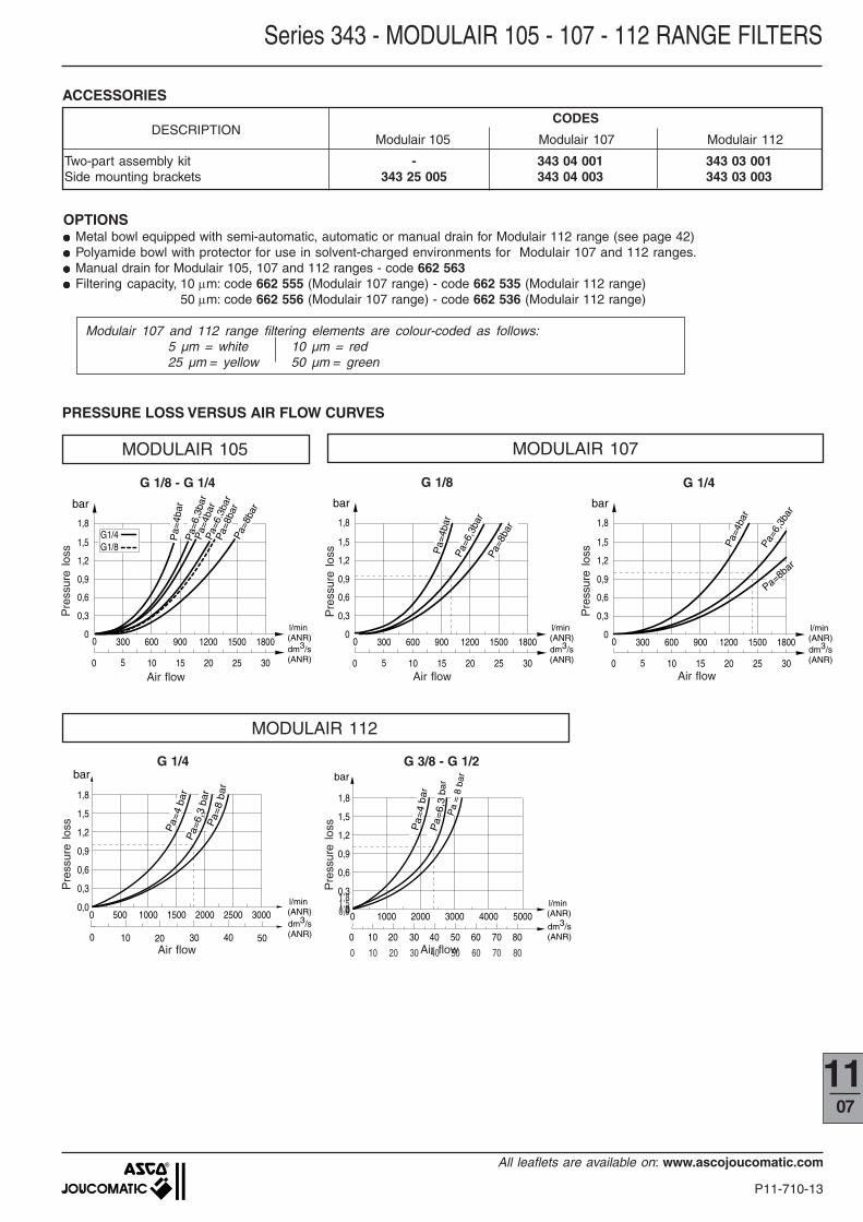
ACCESSORIES
OPTIONSFOR FILTER/REGULATOR●●●●● Additional by-pass insert, 4/6 tube for Modulair 105 - code 685 006●●●●● Metal bowl equipped with semi-automatic, automatic or manual drain for Modulair 112 range (see page 42)●●●●● Polyamide bowl with protector, for use in solvent-charged environments (Modulair 107 and 112 ranges)●●●●● Manual drain for Modulair 105, 107 and 112 ranges - code 662 563.●●●●● Filtering capacity:
- 5 µm: Modulair 105 range - consult usModulair 107, 112, 150 ranges: use the codes corresponding to separate FR and L components (seecorresponding pages) and procure one two-part assembly kit
- 10 µm: code: 662 555 (Modulair 107 range) - code: 662 535 (Modulair 112 range)- 50 µm: code: 662 556 (Modulair 107 range) - code: 662 536 (Modulair 112 range)
●●●●● Key locking device attached to adjustment knob, supplied installed on regulatorcode: 662 561 for Modulair 107 range, and 662 554 for Modulair 112 range
●●●●● Key locking device (A), supplied separately, code: 343 03 050 (fits Modulair 107, 112 and 150 ranges)●●●●● Adjustment range: 0.2 to 3 bar for Modulair 107 and 112 ranges (provide 40/50 mm dia., 0 - 4 bar pressure gauge)
0.5 to 12 bar for Modulair 107 and 112 ranges (provide 50 mm dia., 0 - 16 bar pressure gauge)FOR LUBRICATOR●●●●● Metal bowl for Modulair 112 (see page 42)●●●●● Polyamide bowl with protector for use in solvent-charged environments (Modulair 107 and 112 ranges)●●●●● Lubricator oil refilling while pressurised, code: 662 562 (Modulair 107 range)
PRESSURE LOSS VERSUS AIR FLOW CURVES
(1) Mounting not recommended for Modulair 112 range
Air flow
Out
let
pres
sure
Out
let
pres
sure
Air flow Air flow
Out
let
pres
sure
Air flow Air flow
Out
let
pres
sure
DESCRIPTION
P11-710-11
All leaflets are available on: www.ascojoucomatic.com
1107
62,560,595 97
42
2
38,7
41
G1/4G1/8
max
. 3,5
4
Ø4,5
40
30,241
G1/4G1/8
12511084
2729
54
69
38,7
172
142 16
0
4 x Ø4,5
25
G1/8
36,8
21,5
2 x Ø7
4
2
3
G1/8
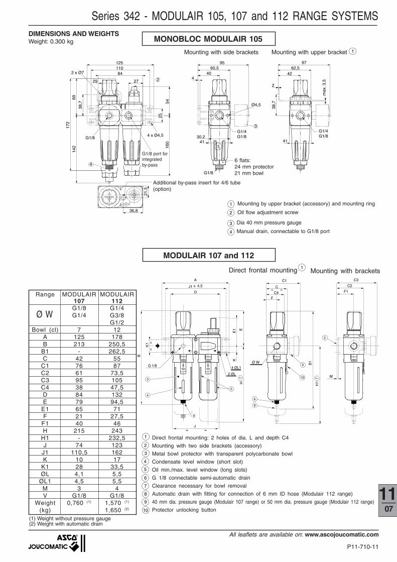
MODULAIR 107 and 112
B
A
J1
D
C3
K1
K
F1
4,5 C2
H
G 1/8
2 ØL
E1 E
3
4
2
5
7
J= =
==
F
C
H1
B1Ø W
C1
6
7
8
10
9
= =
V
±
C4
M•
4 ØL1
1
Ø W
(1) Weight without pressure gauge(2) Weight with automatic drain
Range MODULAIR MODULAIR107 112G1/8 G1/4G1/4 G3/8
G1/2Bowl (cl) 7 12
A 125 178B 213 250,5
B1 - 262,5C 42 55
C1 76 87C2 61 73,5C3 95 105C4 38 47,5D 84 132E 79 94,5
E1 65 71F 21 27,5
F1 40 46H 215 243
H1 - 232,5J 74 123
J1 110,5 162K 10 17
K1 28 33,5ØL 4,1 5,5
ØL1 4,5 5,5M 3 4V G1/8 G1/8
Weight 0,760 (1) 1,570 (1)
(kg) 1,650 (2)
4
10
3
2
1
8
7
6
5
9
Series 342 - MODULAIR 105, 107 and 112 RANGE SYSTEMS
Mounting with bracketsDirect frontal mounting
Direct frontal mounting: 2 holes of dia. L and depth C4
Mounting with two side brackets (accessory)
Metal bowl protector with transparent polycarbonate bowl
Condensate level window (short slot)
Oil min./max. level window (long slots)
G 1/8 connectable semi-automatic drain
Clearance necessary for bowl removal
Automatic drain with fitting for connection of 6 mm ID hose (Modulair 112 range)
40 mm dia. pressure gauge (Modulair 107 range) or 50 mm dia. pressure gauge (Modulair 112 range)
Protector unlocking button
MONOBLOC MODULAIR 105
1
2
4
3
G1/8 port forintegratedby-pass
1
Additional by-pass insert for 4/6 tube(option)
Mounting with side brackets
6 flats:24 mm protector21 mm bowl
DIMENSIONS AND WEIGHTSWeight: 0.300 kg
Mounting by upper bracket (accessory) and mounting ring
Oil flow adjustment screw
Dia 40 mm pressure gauge
Manual drain, connectable to G1/8 port
Mounting with upper bracket
1
P11-710-12
All leaflets are available on: www.ascojoucomatic.com
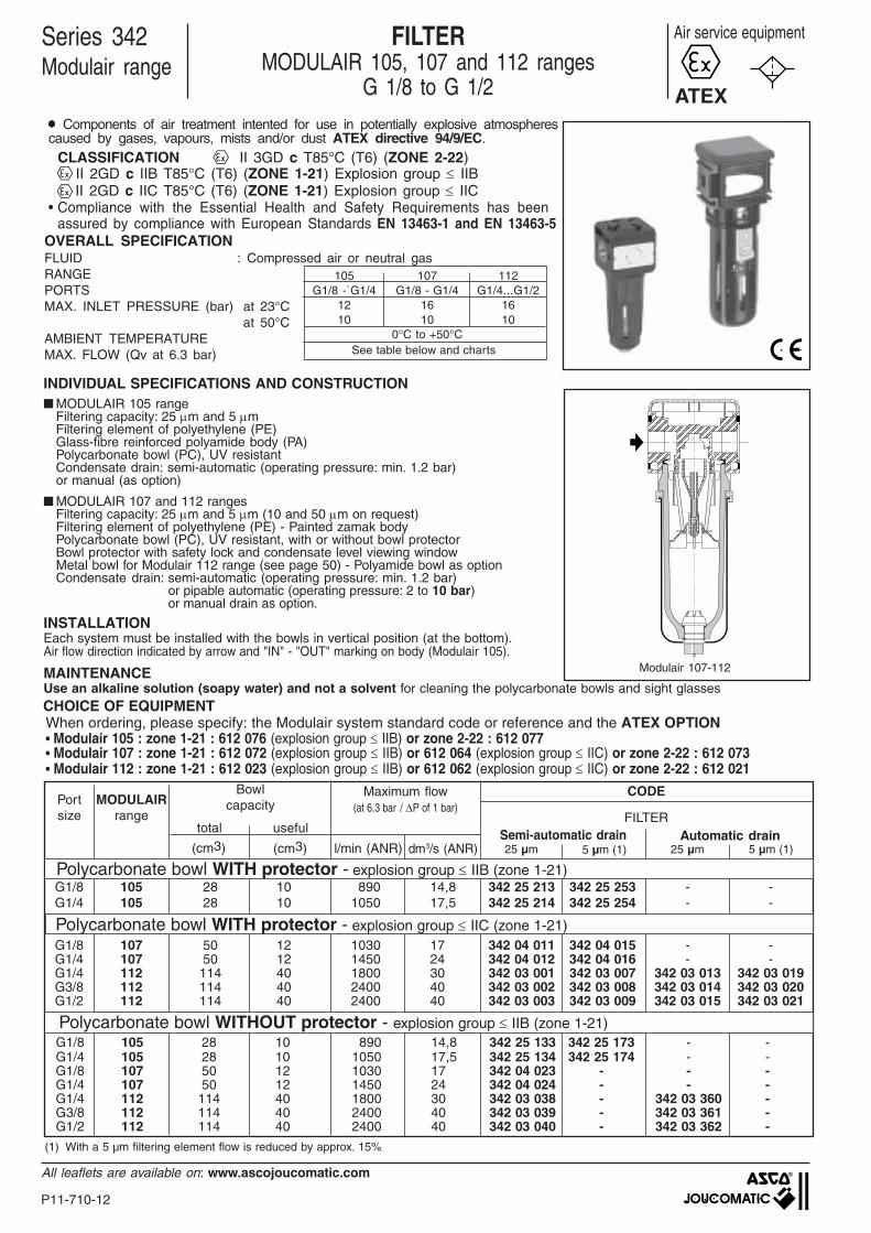
INDIVIDUAL SPECIFICATIONS AND CONSTRUCTION■ MODULAIR 105 range
Filtering capacity: 25 µm and 5 µmFiltering element of polyethylene (PE)Glass-fibre reinforced polyamide body (PA)Polycarbonate bowl (PC), UV resistantCondensate drain: semi-automatic (operating pressure: min. 1.2 bar)or manual (as option)
■ MODULAIR 107 and 112 rangesFiltering capacity: 25 µm and 5 µm (10 and 50 µm on request)Filtering element of polyethylene (PE) - Painted zamak bodyPolycarbonate bowl (PC), UV resistant, with or without bowl protectorBowl protector with safety lock and condensate level viewing windowMetal bowl for Modulair 112 range (see page 50) - Polyamide bowl as optionCondensate drain: semi-automatic (operating pressure: min. 1.2 bar)
or pipable automatic (operating pressure: 2 to 10 bar)or manual drain as option.
INSTALLATIONEach system must be installed with the bowls in vertical position (at the bottom).Air flow direction indicated by arrow and "IN" - "OUT" marking on body (Modulair 105).
MAINTENANCEUse an alkaline solution (soapy water) and not a solvent for cleaning the polycarbonate bowls and sight glasses
��������������������
��
�������������
���������������������������������������������������������������������������������������������������������������������������������������
�
��������������������
��
������������������������������������������������������������������������
���������������������������������������������������������������������������������������������������������������������������������������������������
������������
������������
������������������������
������������������������������������
��������������������������������������������������������
��������������������������������������������������������
����
����
����
����
l/min (ANR) dm3/s (ANR)
G1/8 105 28 10 890 14,8 342 25 213 342 25 253 - -G1/4 105 28 10 1050 17,5 342 25 214 342 25 254 - -
G1/8 107 50 12 1030 17 342 04 011 342 04 015 - -G1/4 107 50 12 1450 24 342 04 012 342 04 016 - -G1/4 112 114 40 1800 30 342 03 001 342 03 007 342 03 013 342 03 019G3/8 112 114 40 2400 40 342 03 002 342 03 008 342 03 014 342 03 020G1/2 112 114 40 2400 40 342 03 003 342 03 009 342 03 015 342 03 021
G1/8 105 28 10 890 14,8 342 25 133 342 25 173 - -G1/4 105 28 10 1050 17,5 342 25 134 342 25 174 - -G1/8 107 50 12 1030 17 342 04 023 - - -G1/4 107 50 12 1450 24 342 04 024 - - -G1/4 112 114 40 1800 30 342 03 038 - 342 03 360 -G3/8 112 114 40 2400 40 342 03 039 - 342 03 361 -G1/2 112 114 40 2400 40 342 03 040 - 342 03 362 -
(cm3) (cm3) 25 µm 5 µm (1)25 µm5 µm (1)
OVERALL SPECIFICATIONFLUID : Compressed air or neutral gasRANGEPORTSMAX. INLET PRESSURE (bar) at 23°C
at 50°CAMBIENT TEMPERATUREMAX. FLOW (Qv at 6.3 bar)
Series 342Modulair range
Air service equipmentFILTERMODULAIR 105, 107 and 112 ranges
G 1/8 to G 1/2
total useful
Polycarbonate bowl WITHOUT protector - explosion group ≤ IIB (zone 1-21)
Semi-automatic drain Automatic drain
Polycarbonate bowl WITH protector - explosion group ≤ IIB (zone 1-21)
CODE
FILTER
CHOICE OF EQUIPMENT
BowlcapacityMODULAIR
rangePortsize
(1) With a 5 µm filtering element flow is reduced by approx. 15%
Maximum flow(at 6.3 bar / ∆P of 1 bar)
Modulair 107-112
105 107 112G1/8 -`G1/4 G1/8 - G1/4 G1/4...G1/2
12 16 1610 10 10
0°C to +50°C See table below and charts
ATEX
When ordering, please specify: the Modulair system standard code or reference and the ATEX OPTION• Modulair 105 : zone 1-21 : 612 076 (explosion group ≤ IIB) or zone 2-22 : 612 077• Modulair 107 : zone 1-21 : 612 072 (explosion group ≤ IIB) or 612 064 (explosion group ≤ IIC) or zone 2-22 : 612 073• Modulair 112 : zone 1-21 : 612 023 (explosion group ≤ IIB) or 612 062 (explosion group ≤ IIC) or zone 2-22 : 612 021
●●●●● Components of air treatment intented for use in potentially explosive atmospherescaused by gases, vapours, mists and/or dust ATEX directive 94/9/EC.
CLASSIFICATION II 3GD c T85°C (T6) (ZONE 2-22) II 2GD c IIB T85°C (T6) (ZONE 1-21) Explosion group ≤ IIB II 2GD c IIC T85°C (T6) (ZONE 1-21) Explosion group ≤ IIC
• Compliance with the Essential Health and Safety Requirements has beenassured by compliance with European Standards EN 13463-1 and EN 13463-5
Polycarbonate bowl WITH protector - explosion group ≤ IIC (zone 1-21)
P11-710-13
All leaflets are available on: www.ascojoucomatic.com
1107
CODES
Modulair 105 Modulair 107 Modulair 112
Two-part assembly kit - 343 04 001 343 03 001Side mounting brackets 343 25 005 343 04 003 343 03 003
MODULAIR 105 MODULAIR 107
G 1/4G 1/8G 1/8 - G 1/4
MODULAIR 112
0 300 600 900 1200 1500 18000
0,3
0,6
0,9
1,2
1,5
1,8
0 5 10 15 20 25 30
l/min (ANR)dm3/s(ANR)
bar
Pa=
4bar
Pa=6
,3ba
r
Pa=8b
ar
0 300 600 900 1200 1500 18000
0,3
0,6
0,9
1,2
1,5
1,8
0 5 10 15 20 25 30
l/min (ANR)dm3/s(ANR)
bar
Pa=
4bar
Pa=
6,3b
arPa
=8ba
r
0 300 600 900 1200 1500 18000
0,3
0,6
0,9
1,2
1,5
1,8
0 5 10 15 20 25 30
l/min (ANR)dm3/s(ANR)
bar
G1/4G1/8
Pa=
4bar
Pa=
6,3b
arP
a=6,
3bar
Pa=
8bar
Pa=
4bar
Pa=
8bar
G 3/8 - G 1/2G 1/4
0 10 20 30 40 500,0
0,30,6
0,91,2
1,5
1,8
0 500 1000 1500 2000 2500 30000,0
0,3
0,6
0,9
1,2
1,5
1,8
0 10 20 30 40 50
bar
Pa=
4ba
rP
a=6,
3ba
rP
a=8
ba
r
dm3/s(ANR)
l/min (ANR)
0 10 20 30 40 50 60 70 80
0,0
0,30,60,6
0,91,21,51,8
0 1000 2000 3000 4000 50000
0,3
0,6
0,9
1,2
1,5
1,8
0 10 20 30 40 50 60 70 80
bar
Pa=
4b
ar
Pa=
6,3
ba
rP
a=
8ba
r
l/min (ANR)
dm3/s(ANR)
ACCESSORIES
Series 343 - MODULAIR 105 - 107 - 112 RANGE FILTERS
DESCRIPTION
OPTIONS●●●●● Metal bowl equipped with semi-automatic, automatic or manual drain for Modulair 112 range (see page 42)●●●●● Polyamide bowl with protector for use in solvent-charged environments for Modulair 107 and 112 ranges.●●●●● Manual drain for Modulair 105, 107 and 112 ranges - code 662 563●●●●● Filtering capacity, 10 µm: code 662 555 (Modulair 107 range) - code 662 535 (Modulair 112 range)
50 µm: code 662 556 (Modulair 107 range) - code 662 536 (Modulair 112 range)
Modulair 107 and 112 range filtering elements are colour-coded as follows:5 µm = white 10 µm = red25 µm = yellow 50 µm = green
PRESSURE LOSS VERSUS AIR FLOW CURVES
Pre
ssur
e lo
ss
Air flowAir flowAir flow
Pre
ssur
e lo
ssP
ress
ure
loss
Air flow
Pre
ssur
e lo
ssP
ress
ure
loss
Air flow
P11-710-14
All leaflets are available on: www.ascojoucomatic.com
MODULAIR 107 and 112
A
J1
D
K1
K
F14,5C2
2 ØL
E
2
6
J= =
==
F
C
B1
Ø W
8
= =±
H 1H 6
5
B
3
7
4
C4
M
•
V
4 ØL1
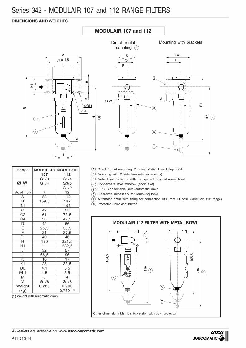
Range MODULAIR MODULAIR107 112G1/8 G1/4G1/4 G3/8
G1/2Bowl (cl) 7 12
A 83 112B 159,5 187
B1 - 198C 42 55
C2 61 73,5C4 38 47,5D 42 66E 25,5 30,5F 21 27,5
F1 40 46H 190 221,5
H1 - 232,5J 32 57
J1 68,5 96K 10 17
K1 28 33,5ØL 4,1 5,5
ØL1 4,5 5,5M 3 4V G1/8 G1/8
Weight 0,280 0,700(kg) 0,780 (1)
Ø W
1
3
2
5
6
7
8
4
1
30,5
6
195,
5
23021
9
6
5
184,
5
7
4
Series 342 - MODULAIR 107 and 112 RANGE FILTERS
Mounting with brackets
(1) Weight with automatic drain
Direct frontal mounting: 2 holes of dia. L and depth C4
Mounting with 2 side brackets (accessory)
Metal bowl protector with transparent polycarbonate bowl
Condensate level window (short slot)
G 1/8 connectable semi-automatic drain
Clearance necessary for removing bowl
Automatic drain with fitting for connection of 6 mm ID hose (Modulair 112 range)
Protector unlocking button
DIMENSIONS AND WEIGHTS
Direct frontalmounting
Other dimensions identical to version with bowl protector
MODULAIR 112 FILTER WITH METAL BOWL
P11-710-15
All leaflets are available on: www.ascojoucomatic.com
1107
MODULAIR 105
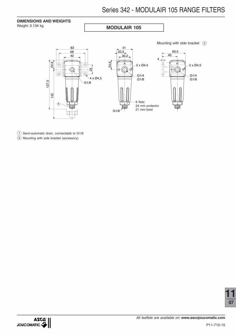
1 Semi-automatic drain, connectable to G1/8
Mounting with side bracket (accessory)2
6883
42
25
G1/84 x Ø4,5
142
127,
5
24,6
4120,5
30,2
2 x Ø4,5
G1/4G1/8
60,540
4
2 x Ø4,5
G1/4G1/8
24,6
1
G1/8
6 flats:24 mm protector21 mm bowl
2
DIMENSIONS AND WEIGHTSWeight: 0.134 kg
Series 342 - MODULAIR 105 RANGE FILTERS
Mounting with side bracket
P11-710-16
All leaflets are available on: www.ascojoucomatic.com
l/min (ANR) dm3/s (ANR) 0-12 bar (1)
G1/8 105 12 0,5-8 550 9 40 342 25 007 342 25 005G1/4 105 12 0,5-8 650 11 40 342 25 008 342 25 006G1/8 107 16 0,5-10 700 11,7 40 342 04 037 342 04 033G1/4 107 16 0,5-10 1300 22 40 342 04 038 342 04 034G1/4 112 16 0,5-10 1800 30 50 342 03 058 342 03 052G3/8 112 16 0,5-10 3000 50 50 342 03 059 342 03 053G1/2 112 16 0,5-10 3000 50 50 342 03 060 342 03 054
G1/8 105 12 0,2-3 550 9 40 342 25 261 342 25 259G1/4 105 12 0,2-3 650 11 40 342 25 262 342 25 260G1/8 107 16 0,2-3 700 11,7 40 342 04 043 342 04 039G1/4 107 16 0,2-3 1300 22 40 342 04 044 342 04 040G1/4 112 16 0,2-3 1800 30 50 342 03 070 342 03 064G3/8 112 16 0,2-3 3000 50 50 342 03 071 342 03 065G1/2 112 16 0,2-3 3000 50 50 342 03 072 342 03 066
(0-4 bar pressure gauge)
������������������������������������������������
��������������������
�����������������������������������
����������������������������������������
���������������
���������������
���������������
���������������
����������������
������������
���������������������������������������������������������������������������������������������������������������������������������������������������������������������������
���������������������������������������������������������������������������������������������������������������������������������������������������������������������������
����������������������������������������������������������������������������������������������������������������������������������������������������������������
���������������
���������������
����������
������������������������������������������������������������������������������������������������������������������
����������������
����������������
•
Modulair 107-112
105 107 112G1/8 -`G1/4 G1/8 - G1/4 G1/4...G1/2
12 16 160,5 - 8 0,5 - 10 0,5 - 10
see table below for other values0,35 0,3 0,2
0°, +50° -10°, +60° -10°, +60°see table below and charts
OVERALL SPECIFICATIONFLUID : Compressed air or neutral gas
: Water or oxygen service on requestRANGEPORTSMAX. INLET PRESSURE (bar)CONTROLLED PRESSURE (bar)
HYSTERESIS (bar)AMBIENT TEMPERATURE (°C)MAX. FLOW (Qv at 6.3 bar)SELF-RELIEVING REGULATOR
Series 342Modulair range
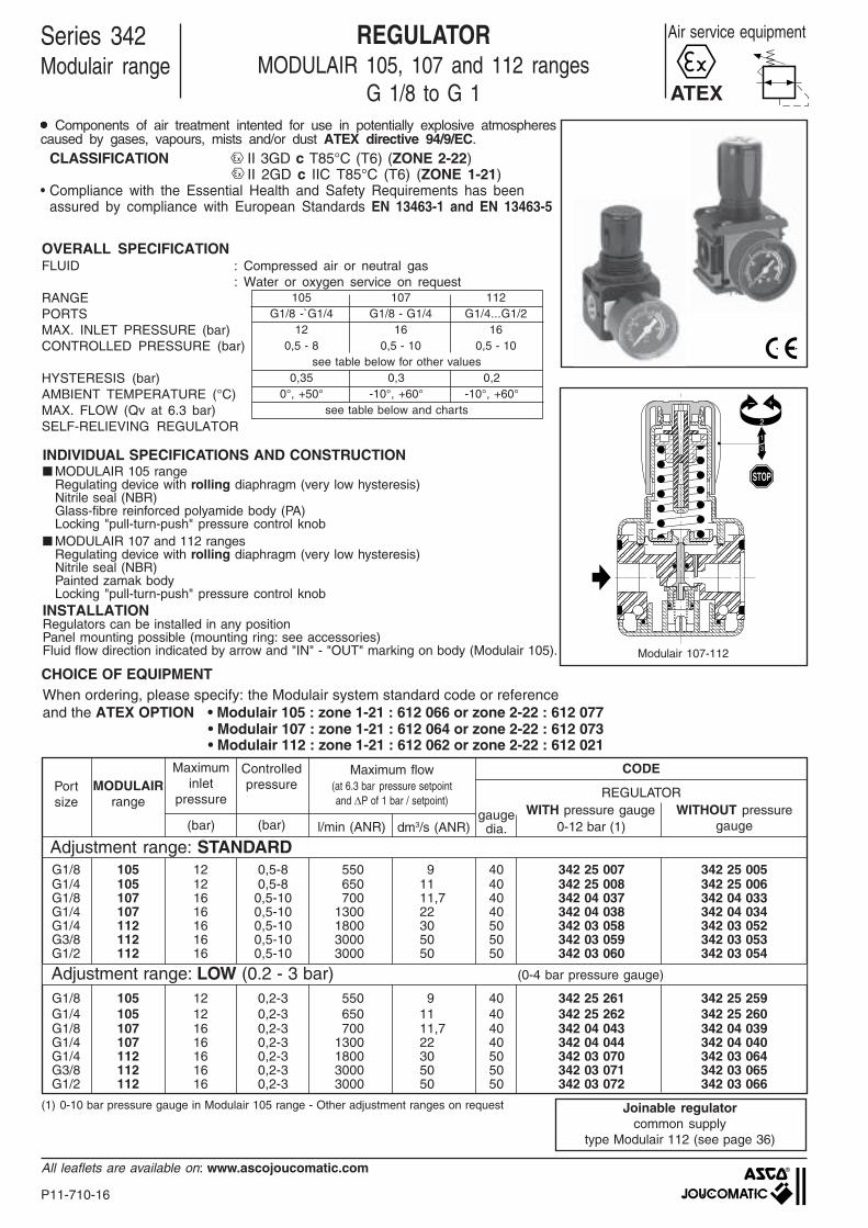
Air service equipmentREGULATORMODULAIR 105, 107 and 112 ranges
G 1/8 to G 1
Adjustment range: STANDARD
Adjustment range: LOW (0.2 - 3 bar)
WITH pressure gauge WITHOUT pressuregauge
gaugedia.
CODE
REGULATOR
CHOICE OF EQUIPMENT
INDIVIDUAL SPECIFICATIONS AND CONSTRUCTION■ MODULAIR 105 range
Regulating device with rolling diaphragm (very low hysteresis)Nitrile seal (NBR)Glass-fibre reinforced polyamide body (PA)Locking "pull-turn-push" pressure control knob
■ MODULAIR 107 and 112 rangesRegulating device with rolling diaphragm (very low hysteresis)Nitrile seal (NBR)Painted zamak bodyLocking "pull-turn-push" pressure control knob
INSTALLATIONRegulators can be installed in any positionPanel mounting possible (mounting ring: see accessories)Fluid flow direction indicated by arrow and "IN" - "OUT" marking on body (Modulair 105).
Maximum flow(at 6.3 bar pressure setpointand ∆P of 1 bar / setpoint)
Portsize
Maximuminlet
pressure
(bar)
MODULAIRrange
(1) 0-10 bar pressure gauge in Modulair 105 range - Other adjustment ranges on request Joinable regulatorcommon supply
type Modulair 112 (see page 36)
Controlledpressure
(bar)
ATEX●●●●● Components of air treatment intented for use in potentially explosive atmospherescaused by gases, vapours, mists and/or dust ATEX directive 94/9/EC.
CLASSIFICATION II 3GD c T85°C (T6) (ZONE 2-22)II 2GD c IIC T85°C (T6) (ZONE 1-21)
• Compliance with the Essential Health and Safety Requirements has beenassured by compliance with European Standards EN 13463-1 and EN 13463-5
When ordering, please specify: the Modulair system standard code or referenceand the ATEX OPTION • Modulair 105 : zone 1-21 : 612 066 or zone 2-22 : 612 077
• Modulair 107 : zone 1-21 : 612 064 or zone 2-22 : 612 073• Modulair 112 : zone 1-21 : 612 062 or zone 2-22 : 612 021

P11-710-17
All leaflets are available on: www.ascojoucomatic.com
1107
CODES
Two-part assembly kit - 343 04 001 343 03 001Top mounting ring 343 00 011 343 00 011 343 00 004Top mounting bracket 343 00 016 343 00 016 343 00 017Side mounting brackets 343 25 005 343 04 003 343 03 00340 mm dia. pressure gauge (0-10 bar) 343 00 014 - -40 mm dia. pressure gauge (0-12 bar) - 343 00 041 -50 mm dia. pressure gauge (0-12 bar) - - 342 00 062
(A)
MODULAIR 105 MODULAIR 107
MODULAIR 112
0 500 1000 1500 2000 2500 30000
1
2
3
4
5
7
6
0 10 20 30 40 50
l/min (ANR)dm3/s(ANR)
barG 1/4
0 300 600 900 1200 1500 18000
1
2
3
4
5
7
6
0 5 10 15 20 25 30
l/min (ANR)dm3/s(ANR)
bar
G1/4G1/8
G 1/8 - G1/4
0 300 600 900 1200 1500 18000
1
2
3
4
5
7
6
0 5 10 15 20 25 30
l/min (ANR)dm3/s(ANR)
barG 1/8
0 20 40 60 80 100
0 1000 2000 3000 4000 5000 60000
1
2
3
4
5
6
7
bar
l/min (ANR)
dm3/s(ANR)
G 3/8 - G 1/2G 1/4
0 500 1000 1500 2000 2500 30000
1
2
3
4
5
6
7
0 10 20 30 40 500
bar
l/min (ANR)
dm3/s(ANR)
ACCESSORIES
DESCRIPTION
OPTIONS●●●●● Key locking device attached to adjustment knob
supplied installed on regulator, code: 662 561 for Modulair 107 range662 554 for Modulair 112 range
●●●●● Key locking device (A), supplied separately, code: 343 03 050 (fits Modulair 107 and 112 ranges)●●●●● Adjustment range: 0.5 to 12 bar for Modulair 107 and 112 ranges
(provide 50 mm dia., 0 - 16 bar pressure gauge)
Series 342 - MODULAIR 105, 107 and 112 RANGE REGULATORS
PRESSURE LOSS VERSUS AIR FLOW CURVES
Air flow
Out
let
pres
sure
Air flow Air flow
Air flowAir flow
Out
let
pres
sure
Out
let
pres
sure
Out
let
pres
sure
Out
let
pres
sure
Modulair 105 Modulair 107 Modulair 112
P11-710-18
All leaflets are available on: www.ascojoucomatic.com
Direct frontalmounting
B
A
J1
D
J2= =
C3
K1
K2
F1
4 ,5 C2
2 x G 1/8 2 ØL
F2
E
2
3
J= =
==
F
C
Ø W
C1
4
= =
±
K
M
M1
max
.
M1
K3
K4Ø L2
E1
4 ØL1
Ø W
Range MODULAIR MODULAIR107 112G1/8 G1/4G1/4 G3/8
G1/2A 83 112B 104 125C 42 55
C1 76 87C2 61 73,5C3 95 105D 42 66E 78,5 94,5
E1 25,5 30,5F 21 27,5
F1 40 46F2 42 42J 32 45
J1 68,5 96J2 29 29K 10 17
K1 28 33,5K2 37,5 42,5K3 51 61K4 53 64ØL 4,1 5,5
ØL1 4,5 5,5ØL2 M30x2 M 37x 2
M 3 4M1 2 2
Weight 0,270 (1) 0,550 (1)
(kg)
1
2
3
4
MODULAIR 107 - 112
Series 342 - MODULAIR 105, 107 and 112 RANGE REGULATORS
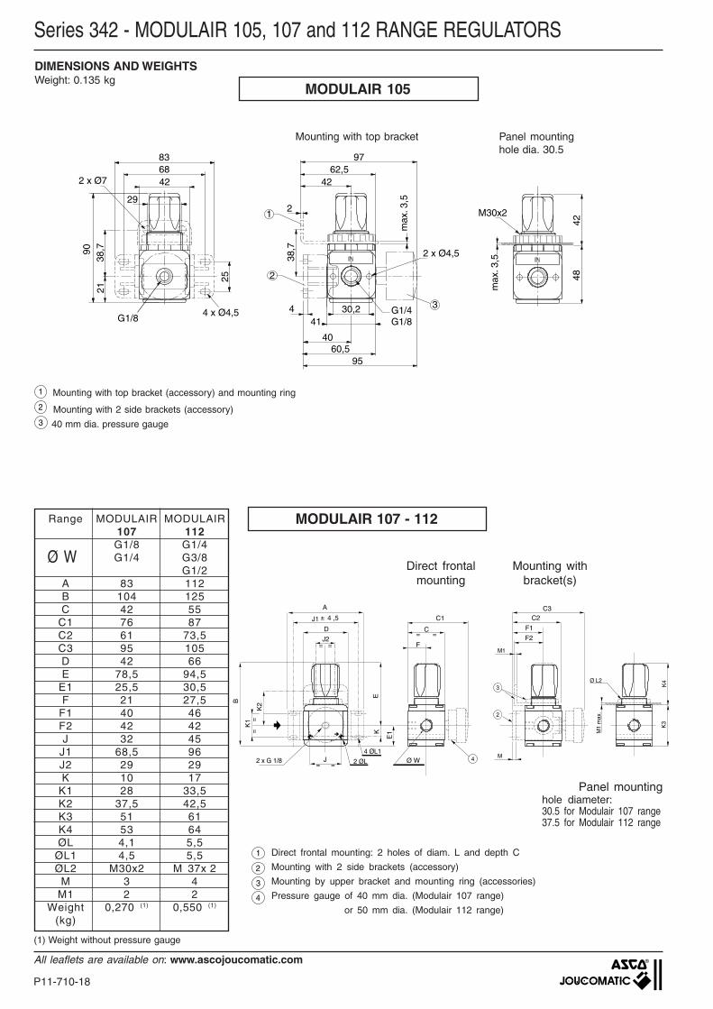
(1) Weight without pressure gauge
Mounting withbracket(s)
Panel mountinghole diameter:30.5 for Modulair 107 range37.5 for Modulair 112 range
Direct frontal mounting: 2 holes of diam. L and depth C
Mounting with 2 side brackets (accessory)
Mounting by upper bracket and mounting ring (accessories)
Pressure gauge of 40 mm dia. (Modulair 107 range)
or 50 mm dia. (Modulair 112 range)
Mounting with top bracket (accessory) and mounting ring
2
1
40 mm dia. pressure gauge
MODULAIR 105
60,595
4
2 x Ø4,5
40
30,241
G1/4G1/8
836842
29
38,790
21
25
G1/8
62,597
42
2
38,7
max
. 3,5
48
max
. 3,5
M30x2
42
4 x Ø4,5
2
1
3
2 x Ø7
3
DIMENSIONS AND WEIGHTSWeight: 0.135 kg
Mounting with top bracket Panel mountinghole dia. 30.5
Mounting with 2 side brackets (accessory)
P11-710-19
All leaflets are available on: www.ascojoucomatic.com
1107
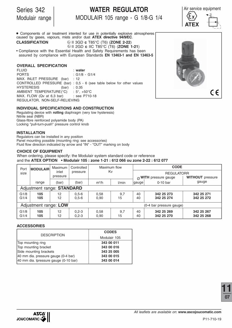
OVERALL SPECIFICATIONFLUID : waterPORTS : G1/8 - G1/4MAX. INLET PRESSURE (bar) : 12CONTROLLED PRESSURE (bar) : 0,5 - 6 (see table below for other valuesHYSTERESIS (bar) : 0.35AMBIENT TEMPERATURE(°C) : 5°, +50°CMAX. FLOW (Qv at 6,3 bar) : see P710-18REGULATOR, NON-SELF-RELIEVING
Series 342Modulair range
WATER REGULATORMODULAIR 105 range - G 1/8-G 1/4
m3/h l/min 0-10 bar
Adjustment range: STANDARDG1/8 105 12 0,5-6 0,58 9,7 40 342 25 273 342 25 271G1/4 105 12 0,5-6 0,90 15 40 342 25 274 342 25 272
Adjustment range: LOWG1/8 105 12 0,2-3 0,58 9,7 40 342 25 269 342 25 267G1/4 105 12 0,2-3 0,90 15 40 342 25 270 342 25 268
WITH pressure gauge WITHOUT pressuregauge
Øgauge
CODE
REGULATORR
CHOICE OF EQUIPMENT
(0-4 bar pressure gauge)
INDIVIDUAL SPECIFICATIONS AND CONSTRUCTIONRegulating device with rolling diaphragm (very low hysteresis)Nitrile seal (NBR)Glass-fibre reinforced polyamide body (PA)Locking "pull-turn-push" pressure control knob
INSTALLATIONRegulators can be installed in any positionPanel mounting possible (mounting ring: see accessories)Fluid flow direction indicated by arrow and "IN" - "OUT" marking on body
Maximum flowKv
Portsize
Maximuminlet
pressure
(bar)
MODULAIR
range
ACCESSORIES
Controlledpressure
(bar)
CODES
Top mounting ring 343 00 011Top mounting bracket 343 00 016Side mounting brackets 343 25 00540 mm dia. pressure gauge (0-4 bar) 343 00 01540 mm dia. lpressure gauge (0-10 bar) 343 00 014
DESCRIPTIONModulair 105
●●●●● Components of air treatment intented for use in potentially explosive atmospherescaused by gases, vapours, mists and/or dust ATEX directive 94/9/EC.CLASSIFICATION II 3GD c T85°C (T6) (ZONE 2-22)
II 2GD c IIC T85°C (T6) (ZONE 1-21)• Compliance with the Essential Health and Safety Requirements has been
assured by compliance with European Standards EN 13463-1 and EN 13463-5
When ordering, please specify: the Modulair system standard code or referenceand the ATEX OPTION • Modulair 105 : zone 1-21 : 612 066 ou zone 2-22 : 612 077
ATEX
Air service equipment

P11-710-20
All leaflets are available on: www.ascojoucomatic.com
Series 342 - WATER REGULATOR MODULAIR 105 RANGE
DIMENSIONS AND WEIGHTSWeight: 0.130 kg
Mounting with bracket(s)
2
1
Dia. 40 mm pressure gauge
Mounting with top bracket (accessory) and ring
60,595
4
2 x Ø4,5
40
30,241
G1/4G1/8
836842
29
38,790
21
25
G1/8
62,597
42
2
38,7
max
. 3,5
48
max
. 3,5
M30x2
42
4 x Ø4,5
2
1
3
2 x Ø7
Mounting with 2 side brackets (accessory)
3
Panel mountingHole dia.: 30.5
P11-710-21
All leaflets are available on: www.ascojoucomatic.com
1107
105 107 112G1/8 -`G1/4 G1/8 - G1/4 G1/4...G1/2
12 16 1610 10 10
0,5 - 8 0,5 - 10 0,5 - 10See options for other values
0,35 0,3 0,20°C to +50°C
See table below and chartsSelf-relieving
Modulair 107-112
���������������������������������������������������������������
����������������
������������
����������������������������
��������������������
����������������
����������������
������
���������������
������������
��������������������
��������������������
������������
����������������
��������������������������������������������������������������������������������������������������������������������������������������������������������
��������������������������������������������������������������������������������������������������������������������������������������������������������
������������������������������������������������������������������������������������������������������������������������������������������������������������������������
������������������������
���������������
���������������
������������������������������������������������������������������������������������������
������������
������������
������������������������������������
������������������������������������������������������
������������������������
���������������������������������������������������������������
����������������
������
���� ���
������
����
¥
���
���
l/min (ANR) dm3/s (ANR)
G1/8 105 28 25 0,5-8 550 9 40 342 25 203 342 25 201 - -G1/4 105 28 25 0,5-8 650 11 40 342 25 204 342 25 202 - -
G1/8 107 50 25 0,5-10 700 11,7 40 342 04 049 342 04 045 - -G1/4 107 50 25 0,5-10 1300 22 40 342 04 050 342 04 046 - -G1/4 112 114 25 0,5-10 1800 30 50 342 03 086 342 03 080 342 03 135 342 03 129G3/8 112 114 25 0,5-10 3000 50 50 342 03 087 342 03 081 342 03 136 342 03 130G1/2 112 114 25 0,5-10 3000 50 50 342 03 088 342 03 082 342 03 137 342 03 131
G1/8 107 50 5 0,5-10 600 10 40 342 04 055 342 04 051 - -G1/4 107 50 5 0,5-10 1100 18 40 342 04 056 342 04 052 - -G1/4 112 114 5 0,5-10 1500 25 50 342 03 098 342 03 092 342 03 147 342 03 141G3/8 112 114 5 0,5-10 2500 42 50 342 03 099 342 03 093 342 03 148 342 03 142G1/2 112 114 5 0,5-10 2500 42 50 342 03 100 342 03 094 342 03 149 342 03 143
G1/8 105 28 25 0,5-8 550 9 40 342 25 123 342 25 121 - -G1/4 105 28 25 0,5-8 650 11 40 342 25 124 342 25 122 - -G1/8 107 50 25 0,5-10 700 11,7 40 342 04 073 342 04 069 - -G1/4 107 50 25 0,5-10 1300 22 40 342 04 074 342 04 070 - -G1/4 112 114 25 0,5-10 1800 30 50 342 03 372 342 03 340 342 03 378 342 03 375G3/8 112 114 25 0,5-10 3000 50 50 342 03 373 342 03 341 342 03 379 342 03 376G1/2 112 114 25 0,5-10 3000 50 50 342 03 374 342 03 342 342 03 380 342 03 377
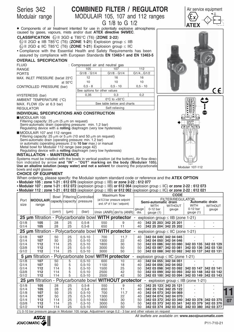
COMBINED FILTER / REGULATORMODULAIR 105, 107 and 112 ranges
G 1/8 to G 1/2
Air service equipment
OVERALL SPECIFICATIONFLUID : Compressed air and neutral gasRANGEPORTSMAX. INLET PRESSURE (bar)at 23°C at 50°CCONTROLLED PRESSURE (bar)
HYSTERESIS (bar)AMBIENT TEMPERATURE (°C)MAX. FLOW (Qv at 6.3 bar)REGULATORINDIVIDUAL SPECIFICATIONS AND CONSTRUCTION■ MODULAIR 105
Filtering capacity: 25 µm (5 µm on request)Semi-automatic drain (operating pressure: min. 1.2 bar)Regulating device with a rolling diaphragm (very low hysteresis)
■ MODULAIR 107 and 112 rangesFiltering capacity: 25 µm or 5 µm (10 and 50 µm on request)Semi-automatic drain (operating pressure: min. 1.2 bar)or automatic (operating pressure: 2 to 10 bar max.) or manualMetal bowl for Modulair 112 range (see page 42)Regulating device with a rolling diaphragm (very low hysteresis)
INSTALLATION - MAINTENANCESystems must be installed with the bowls in vertical position (at the bottom). Air flow direc-tion indicated by arrow and "IN" - "OUT" marking on the body (Modulair 105).Use an alkaline solution (soapy water) and not a solvent for cleaning the polycarbonatebowls and sight glasses
MODULAIRrange
gaugedia.
WITH0-12 bargauge (1)
WITH0-12 bar
gauge (1)
WITHOUTgauge
WITHOUTgauge
Semi-automatic drain Automatic drain
CODEFILTER/REGULATOR
25 µm filtration - Polycarbonate bowl WITH protector - explosion group ≤ IIB (zone 1-21)
25 µm filtration - Polycarbonate bowl WITHOUT protector - explosion group ≤ IIB (zone 1-21)
5 µm filtration - Polycarbonate bowl WITH protector - explosion group ≤ IIC (zone 1-21)
(1) 0-10 bar pressure gauge in Modulair 105 range. Adjustment range 0.2 - 3 bar and other values on request
Maximum flow(at 6.3 bar pressure setpointand ∆P of 1 bar / setpoint)
Controlledpressure
(bar)
Filteringcapacity
(µm)
Bowlcapacity
(cm3)
Portsize
CHOICE OF EQUIPMENT
Series 342Modulair range
ATEX●●●●● Components of air treatment intented for use in potentially explosive atmospherescaused by gases, vapours, mists and/or dust ATEX directive 94/9/EC.CLASSIFICATION II 3GD c T85°C (T6) (ZONE 2-22)
II 2GD c IIB T85°C (T6) (ZONE 1-21) Explosion group ≤ IIB II 2GD c IIC T85°C (T6) (ZONE 1-21) Explosion group ≤ IIC
• Compliance with the Essential Health and Safety Requirements has beenassured by compliance with European Standards EN 13463-1 and EN 13463-5
When ordering, please specify: the Modulair system standard code or reference and the ATEX OPTION• Modulair 105 : zone 1-21 : 612 076 (explosion group ≤ IIB) or zone 2-22 : 612 077• Modulair 107 : zone 1-21 : 612 072 (explosion group ≤ IIB) or 612 064 (explosion group ≤ IIC) or zone 2-22 : 612 073• Modulair 112 : zone 1-21 : 612 023 (explosion group ≤ IIB) or 612 062 (explosion group ≤ IIC) or zone 2-22 : 612 021
25 µm filtration - Polycarbonate bowl WITH protector - explosion group ≤ IIC (zone 1-21)

P11-710-22
All leaflets are available on: www.ascojoucomatic.com
CODES
Two-part assembly kit - 343 04 001 343 03 001Top mounting ring 343 00 011 343 00 011 343 00 004Top mounting bracket 343 00 016 343 00 016 343 00 017Side mounting brackets 343 25 005 343 04 003 343 03 00340 mm dia. pressure gauge (0-10 bar) 343 00 014 - -40 mm dia. pressure gauge (0-12 bar) - 343 00 041 -50 mm dia. pressure gauge (0-12 bar) - - 342 00 062
Modulair 105 Modulair 107 Modulair 112
(A)
MODULAIR 105 MODULAIR 107
0 500 1000 1500 2000 2500 30000
1
2
3
4
5
7
6
0 10 20 30 40 50
l/min (ANR)dm3/s(ANR)
bar
MODULAIR 112
G 1/4
0 300 600 900 1200 1500 18000
1
2
3
4
5
7
6
0 5 10 15 20 25 30
l/min (ANR)dm3/s(ANR)
bar
G1/4G1/8
G 1/8 - G1/4
0 300 600 900 1200 1500 18000
1
2
3
4
5
7
6
0 5 10 15 20 25 30
l/min (ANR)dm3/s(ANR)
barG 1/8
G 1/4
0 500 1000 1500 2000 2500 30000
1
2
3
4
5
6
7
0 10 20 30 40 500
bar
l/min (ANR)
dm3/s(ANR)
G 3/8 - G 1/2
0 10 20 30 40 50 60 70 800
1
1
2
3
4
5
6
7
bar
1000 2000 4000 50000 30000
l/min (ANR)
dm3/s(ANR)
Series 342 - MODULAIR 105 to 112 RANGE FILTERS/REGULATORS
ACCESSORIES
DESCRIPTION
OPTIONSFOR FILTER/REGULATOR●●●●● Metal bowl equipped with semi-automatic, automatic or manual drain for Modulair 112 range (see page 42)●●●●● Polyamide bowl with protector for use in solvent-charged environments (Modulair 107 and 112 ranges)●●●●● Manual drain for Modulair 105, 107 and112 ranges - code 662 563●●●●● Filtering capacity:
- 5 µm : (consult us for Modulair 105 range)- 10 µm: code 662 555 (Modulair 107 range) - code 662 535 (Modulair 112 range)- 50 µm: code 662 556 (Modulair 107 range) - code 662 536 (Modulair 112 range)
●●●●● Key locking device for adjustment knob, attached to knob, supplied installed on regulator,code: 662 561 for Modulair 107 range, 662 554 for Modulair 112 range
●●●●● Key locking device (A), supplied separately, code: 343 03 050 (fits Modulair 107 and 112 ranges)●●●●● Adjustment range:0.2 to 3 bar, for Modulair 105, 107 and 112 ranges
(provide 40/50 mm dia. 0 - 4 bar pressure gauge) codes: 343 00 015 - 342 00 0610.5 to 12 bar, for Modulair 107 and 112 ranges (provide 50 mm dia. 0 - 16 bar pressure gauge)
PRESSURE LOSS VERSUS AIR FLOW CURVES
Air flow
Out
let
pres
sure
Out
let
pres
sure
Air flow Air flow
Out
let
pres
sure
Air flow
Out
let
pres
sure
Air flow
Out
let
pres
sure
P11-710-23
All leaflets are available on: www.ascojoucomatic.com
1107
B
A
J1
D
J2= =
C3
K1
K2
F1
4,5 C2
H
G 1/8
2 ØL
F2
E
3
4
7
2
J= =
==
Ø 5
0
F
C
H 1
B1Ø W
C1
56
7
9
8
= =
V
±
K
C4
M
10
M1
•
4 ØL1
Range107 112G1/8 G1/4G1/4 G3/8
G1/2Bowl (cl) 7 12
A 83 112B 213 251
B1 - 262C 42 55
C1 76 87C2 61 73,5C3 95 105C4 38 47,5D 42 66E 79 94,5F 21 27,5
F1 40 46F2 42 42H 190 221,5
H1 - 232,5J 32 57
J1 68,5 96J2 29 29K 10 17
K1 28 33,5K2 37,5 42,5ØL 4,1 5,5
ØL1 4,5 5,5M 3 4
M1 2 2V G1/8 G1/8
Weight 0,380(1) 0,830(1)
(kg) 0,910(2)
Ø W
1
MODULAIR MODULAIR 1
2
3
4
6
8
7
9
5
10
94,5
7
259,
5
23021
9
7
6
248,
5
8
5
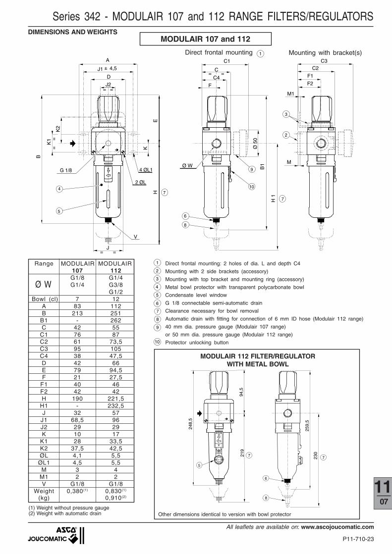
Series 342 - MODULAIR 107 and 112 RANGE FILTERS/REGULATORS
(1) Weight without pressure gauge(2) Weight with automatic drain
DIMENSIONS AND WEIGHTSMODULAIR 107 and 112
Direct frontal mounting Mounting with bracket(s)
Direct frontal mounting: 2 holes of dia. L and depth C4
Mounting with 2 side brackets (accessory)
Mounting with top bracket and mounting ring (accessory)
Metal bowl protector with transparent polycarbonate bowl
Condensate level window
G 1/8 connectable semi-automatic drain
Clearance necessary for bowl removal
Automatic drain with fitting for connection of 6 mm ID hose (Modulair 112 range)
40 mm dia. pressure gauge (Modulair 107 range)
or 50 mm dia. pressure gauge (Modulair 112 range)
Protector unlocking button
MODULAIR 112 FILTER/REGULATORWITH METAL BOWL
Other dimensions identical to version with bowl protector

P11-710-24
All leaflets are available on: www.ascojoucomatic.com
62,560,595 97
42
2
38,7
41
G1/4G1/8
max
. 3,5
4
Ø4,5
40
30,241
G1/4G1/8
836842
29
69
38,7
172
142
25
G1/8
2
G1/8
3
4 x Ø4,5
2 x Ø7
MODULAIR 105
Mounting with top bracket
1
2
3
Mounting with side brackets 1
6 flats:24 mm protector21 mm bowl
Series 342 - MODULAIR 105 RANGE FILTERS/REGULATORSDIMENSIONS AND WEIGHTSWeight: 0.190kg
40 mm dia. pressure gaugeMounting with top bracket (accessory) and mounting ring
Semi-automatic drain, connectable to G1/8 port
P11-710-25
All leaflets are available on: www.ascojoucomatic.com
1107
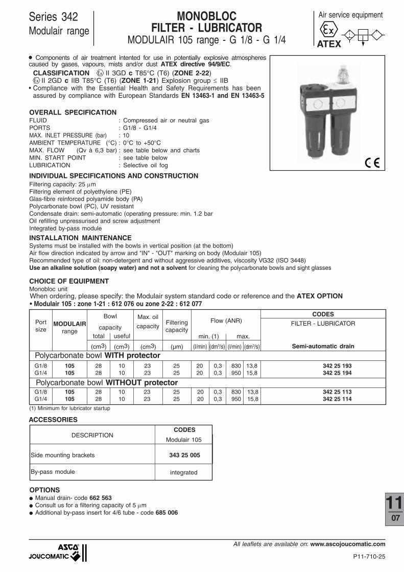
OVERALL SPECIFICATIONFLUID : Compressed air or neutral gasPORTS : G1/8 - G1/4MAX. INLET PRESSURE (bar) : 10AMBIENT TEMPERATURE (°C) : 0°C to +50°CMAX. FLOW (Qv à 6,3 bar) : see table below and chartsMIN. START POINT : see table belowLUBRICATION : Selective oil fog
Series 342Modulair range
Air service equipmentMONOBLOCFILTER - LUBRICATOR
MODULAIR 105 range - G 1/8 - G 1/4
INDIVIDUAL SPECIFICATIONS AND CONSTRUCTIONFiltering capacity: 25 µmFiltering element of polyethylene (PE)Glas-fibre reinforced polyamide body (PA)Polycarbonate bowl (PC), UV resistantCondensate drain: semi-automatic (operating pressure: min. 1.2 barOil refilling unpressurised and screw adjustmentIntegrated by-pass module
INSTALLATION MAINTENANCESystems must be installed with the bowls in vertical position (at the bottom)Air flow direction indicated by arrow and "IN" - "OUT" marking on body (Modulair 105)Recommended type of oil: non-detergent and without aggressive additives, viscosity VG32 (ISO 3448)Use an alkaline solution (soapy water) and not a solvent for cleaning the polycarbonate bowls and sight glasses
CHOICE OF EQUIPMENTMonobloc unit
(1) Minimum for lubricator startup
ACCESSORIESCODES
DESCRIPTIONModulair 105
Side mounting brackets 343 25 005
By-pass module integrated
OPTIONS●●●●● Manual drain- code 662 563●●●●● Consult us for a filtering capacity of 5 µm●●●●● Additional by-pass insert for 4/6 tube - code 685 006
(l/min) (dm3/s) (l/min) (dm3/s) Semi-automatic drain
CODES
FILTER - LUBRICATOR
min. (1) max.
(cm3) (µm)
Flow (ANR)MODULAIRrange
Bowl
capacityFilteringcapacity
Polycarbonate bowl WITH protectorG1/8 105 28 10 23 25 20 0,3 830 13,8 342 25 193G1/4 105 28 10 23 25 20 0,3 950 15,8 342 25 194
G1/8 105 28 10 23 25 20 0,3 830 13,8 342 25 113G1/4 105 28 10 23 25 20 0,3 950 15,8 342 25 114
Polycarbonate bowl WITHOUT protector
Portsize
(cm3)
total useful
Max. oil
capacity
(cm3)
When ordering, please specify: the Modulair system standard code or reference and the ATEX OPTION• Modulair 105 : zone 1-21 : 612 076 ou zone 2-22 : 612 077
ATEX●●●●● Components of air treatment intented for use in potentially explosive atmospherescaused by gases, vapours, mists and/or dust ATEX directive 94/9/EC.
CLASSIFICATION II 3GD c T85°C (T6) (ZONE 2-22) II 2GD c IIB T85°C (T6) (ZONE 1-21) Explosion group ≤ IIB
• Compliance with the Essential Health and Safety Requirements has beenassured by compliance with European Standards EN 13463-1 and EN 13463-5
P11-710-26
All leaflets are available on: www.ascojoucomatic.com
0 300 600 900 1200 1500 18000
0,3
0,6
0,9
1,2
1,5
1,8
0 5 10 15 20 25 30
l/min (ANR)dm3/s(ANR)
bar
G1/4G1/8
Pa=
6,3b
ar
Pa=
4bar
Pa=
8bar
Pa=
6,3b
ar
Pa=
4bar
Pa=
8bar
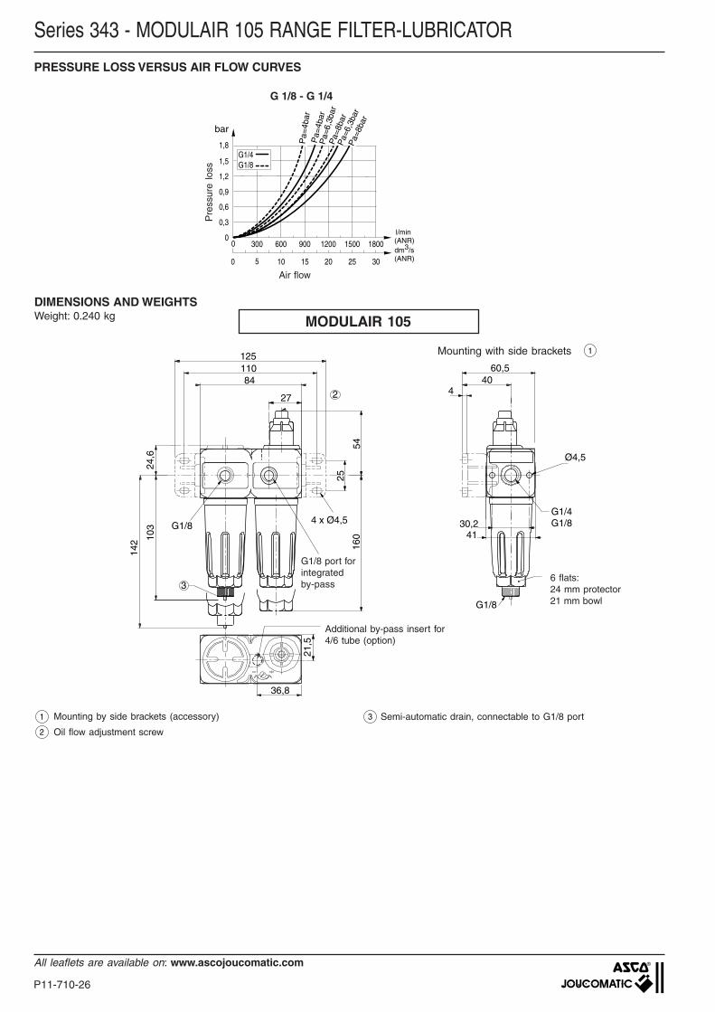
Series 343 - MODULAIR 105 RANGE FILTER-LUBRICATOR
PRESSURE LOSS VERSUS AIR FLOW CURVES
G 1/8 - G 1/4
Air flow
Pre
ssur
e lo
ss
DIMENSIONS AND WEIGHTSWeight: 0.240 kg MODULAIR 105
60,5
4
Ø4,5
40
30,241
G1/4G1/8
12511084
27
54
24,6
142 10
3
160
4 x Ø4,5
25
G1/8
36,8
21,5
3
2
G1/8
6 flats:24 mm protector21 mm bowl
1
2
Mounting by side brackets (accessory)
Oil flow adjustment screw
Semi-automatic drain, connectable to G1/8 port3
1
Additional by-pass insert for4/6 tube (option)
Mounting with side brackets
G1/8 port forintegratedby-pass
P11-710-27
All leaflets are available on: www.ascojoucomatic.com
1107
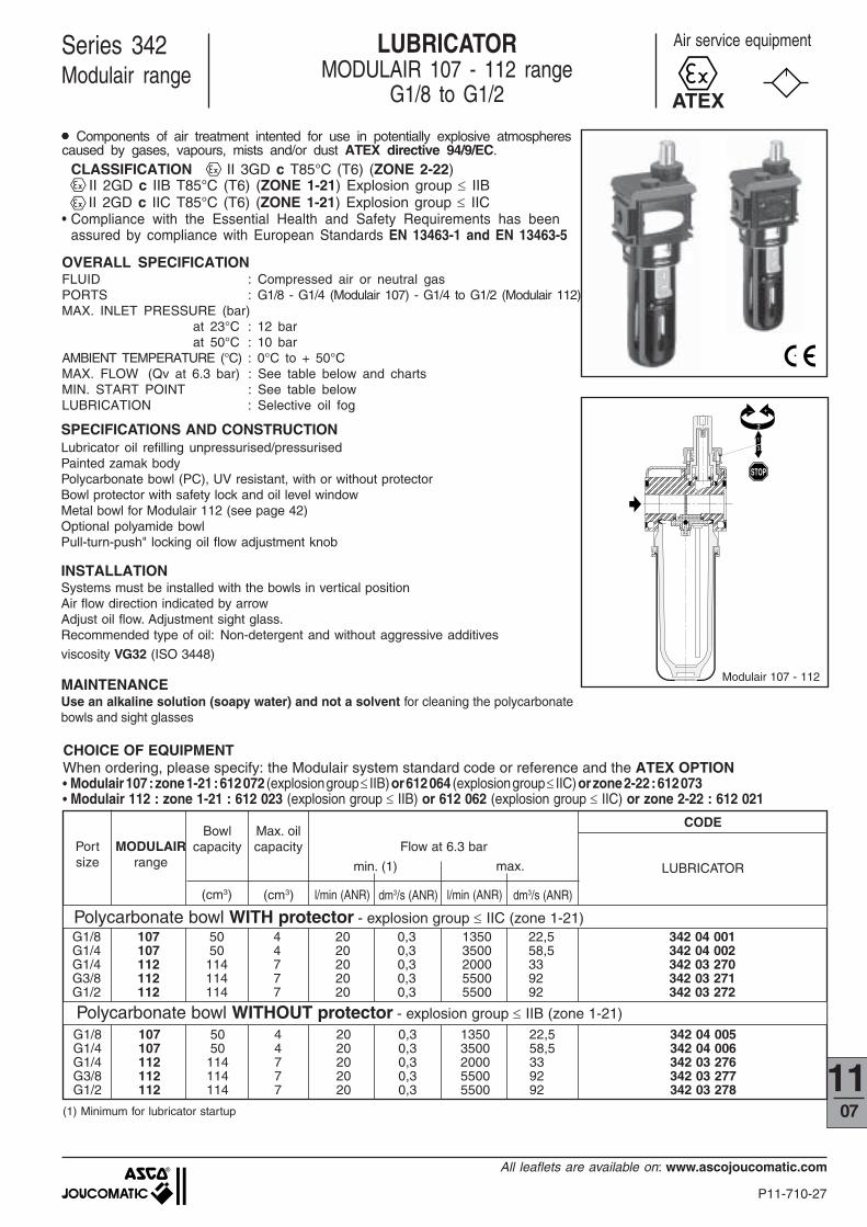
LUBRICATORMODULAIR 107 - 112 range
G1/8 to G1/2
Series 342Modulair range
������������������������������������
������������������������������������������������������������
������������������������
������������������������
���������������
���������������
������������������������������
���������
����������������������������������������������������������������������������
����������������
��������������������
������
���� ��
��
����
•
SPECIFICATIONS AND CONSTRUCTIONLubricator oil refilling unpressurised/pressurisedPainted zamak bodyPolycarbonate bowl (PC), UV resistant, with or without protectorBowl protector with safety lock and oil level windowMetal bowl for Modulair 112 (see page 42)Optional polyamide bowlPull-turn-push" locking oil flow adjustment knob
INSTALLATIONSystems must be installed with the bowls in vertical positionAir flow direction indicated by arrowAdjust oil flow. Adjustment sight glass.Recommended type of oil: Non-detergent and without aggressive additives
viscosity VG32 (ISO 3448)
MAINTENANCEUse an alkaline solution (soapy water) and not a solvent for cleaning the polycarbonatebowls and sight glasses
G1/8 107 50 4 20 0,3 1350 22,5 342 04 001G1/4 107 50 4 20 0,3 3500 58,5 342 04 002G1/4 112 114 7 20 0,3 2000 33 342 03 270G3/8 112 114 7 20 0,3 5500 92 342 03 271G1/2 112 114 7 20 0,3 5500 92 342 03 272
(cm3) (cm3)
CHOICE OF EQUIPMENT
dm3/s (ANR)l/min (ANR) dm3/s (ANR)l/min (ANR)
Bowlcapacity
CODE
LUBRICATOR
G1/8 107 50 4 20 0,3 1350 22,5 342 04 005G1/4 107 50 4 20 0,3 3500 58,5 342 04 006G1/4 112 114 7 20 0,3 2000 33 342 03 276G3/8 112 114 7 20 0,3 5500 92 342 03 277G1/2 112 114 7 20 0,3 5500 92 342 03 278
Polycarbonate bowl WITHOUT protector - explosion group ≤ IIB (zone 1-21)
Polycarbonate bowl WITH protector - explosion group ≤ IIC (zone 1-21)
(1) Minimum for lubricator startup
MODULAIRrange min. (1) max.
Flow at 6.3 barMax. oilcapacityPort
size
Modulair 107 - 112
Air service equipment
ATEX
OVERALL SPECIFICATIONFLUID : Compressed air or neutral gasPORTS : G1/8 - G1/4 (Modulair 107) - G1/4 to G1/2 (Modulair 112)MAX. INLET PRESSURE (bar)
at 23°C : 12 barat 50°C : 10 bar
AMBIENT TEMPERATURE (°C) : 0°C to + 50°CMAX. FLOW (Qv at 6.3 bar) : See table below and chartsMIN. START POINT : See table belowLUBRICATION : Selective oil fog
When ordering, please specify: the Modulair system standard code or reference and the ATEX OPTION• Modulair 107 : zone 1-21 : 612 072 (explosion group ≤ IIB) or 612 064 (explosion group ≤ IIC) or zone 2-22 : 612 073• Modulair 112 : zone 1-21 : 612 023 (explosion group ≤ IIB) or 612 062 (explosion group ≤ IIC) or zone 2-22 : 612 021
●●●●● Components of air treatment intented for use in potentially explosive atmospherescaused by gases, vapours, mists and/or dust ATEX directive 94/9/EC.
CLASSIFICATION II 3GD c T85°C (T6) (ZONE 2-22) II 2GD c IIB T85°C (T6) (ZONE 1-21) Explosion group ≤ IIB II 2GD c IIC T85°C (T6) (ZONE 1-21) Explosion group ≤ IIC
• Compliance with the Essential Health and Safety Requirements has beenassured by compliance with European Standards EN 13463-1 and EN 13463-5
P11-710-28
All leaflets are available on: www.ascojoucomatic.com
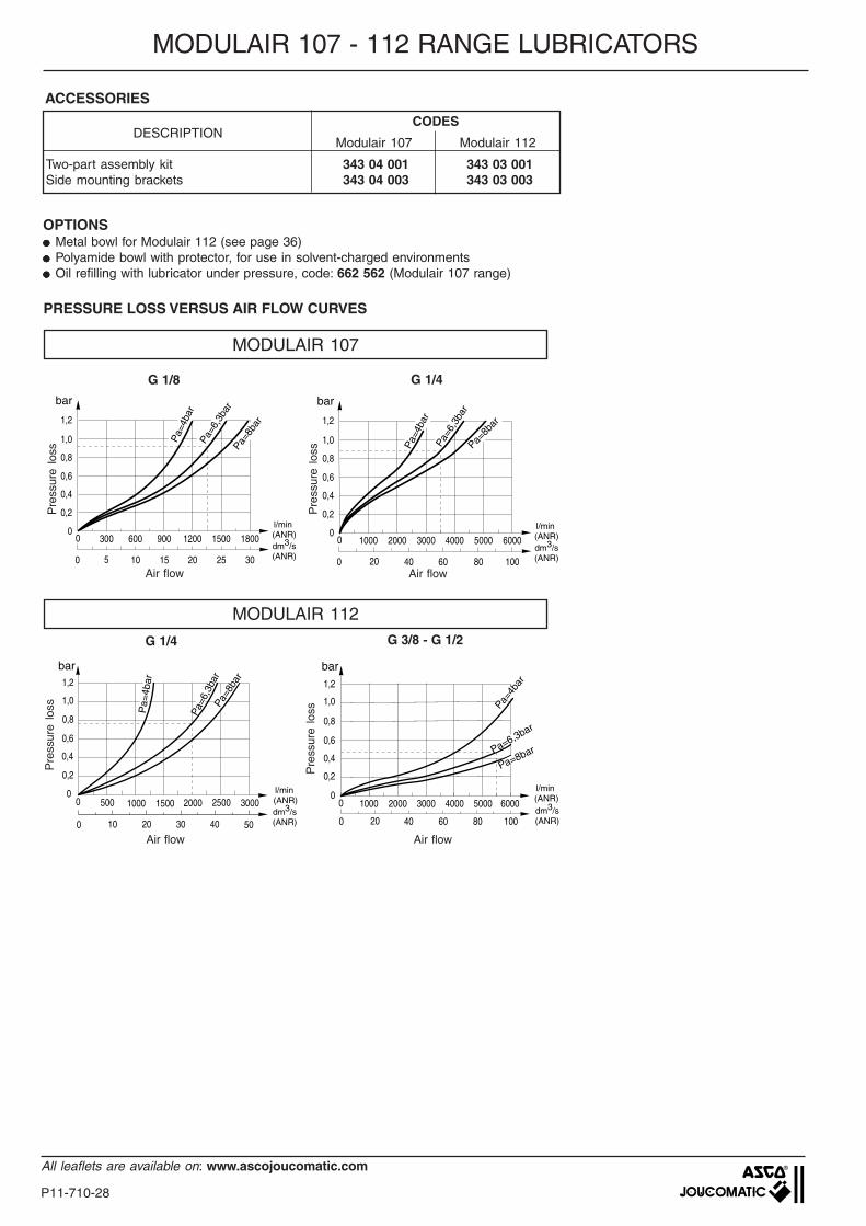
ACCESSORIES
MODULAIR 107 - 112 RANGE LUBRICATORS
Air flow
G 1/4
bar
Pa=
4bar
Pa=
6,3b
arPa
=8ba
r
00
0,2
0,4
0,6
0,8
1,0
1,2
500 1000 1500 2000 2500 3000
0 10 20 30 40 50
l/min (ANR)dm3/s(ANR)
Air flow
G 3/8 - G 1/2
0 1000 2000 3000 4000 5000 60000
0,2
0,4
0,6
0,8
1,0
1,2
0 20 40 60 80 100
bar
Pa=4b
ar
Pa=6,3bar
Pa=8bar
l/min (ANR)dm3/s(ANR)
OPTIONS●●●●● Metal bowl for Modulair 112 (see page 36)●●●●● Polyamide bowl with protector, for use in solvent-charged environments●●●●● Oil refilling with lubricator under pressure, code: 662 562 (Modulair 107 range)
Pre
ssur
e lo
ss
Pre
ssur
e lo
ss
CODESDESCRIPTION
Modulair 107 Modulair 112
Two-part assembly kit 343 04 001 343 03 001Side mounting brackets 343 04 003 343 03 003
PRESSURE LOSS VERSUS AIR FLOW CURVES
MODULAIR 107
MODULAIR 112
G 1/4
0 1000 2000 3000 4000 5000 60000
0,2
0,4
0,6
0,8
1,0
1,2
0 20 40 60 80 100
l/min (ANR)dm3/s(ANR)
barP
a=4b
arPa
=6,3
bar
Pa=8b
ar
Air flow
Pre
ssur
e lo
ss
G 1/8
0 300 600 900 1200 1500 18000
0,2
0,4
0,6
0,8
1,0
1,2
0 5 10 15 20 25 30
l/min (ANR)dm3/s(ANR)
bar
Pa=8b
ar
Pa=
4bar
Pa=6
,3ba
r
Air flow
Pre
ssur
e lo
ss
P11-710-29
All leaflets are available on: www.ascojoucomatic.com
1107
MODULAIR 107 - 112 RANGE LUBRICATORS
1
2
4
3
6
5
7
A
J1
D
K1
K
F14,5
C2
2 ØL
E
44
J= =
==
F
C
BØ W
5
= =±
H2
C4
M
6
3•
7
4 ØL1
8
Max.
Min.
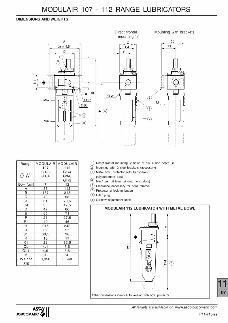
Direct frontalmounting
DIMENSIONS AND WEIGHTS
Mounting with brackets1
8
Direct frontal mounting: 2 holes of dia. L and depth C4
Mounting with 2 side brackets (accessory)
Metal bowl protector with transparent
polycarbonate bowl
Min./max. oil level window (long slots)
Clearance necessary for bowl removal
Protector unlocking button
Filler plug
Oil flow adjustment knob
71
216
5244
MODULAIR 112 LUBRICATOR WITH METAL BOWL
Other dimensions identical to version with bowl protector
Range MODULAIR MODULAIR107 112G1/8 G1/4G1/4 G3/8
G1/2Bowl (cm3) 7 12
A 83 112B 187 215C 42 55
C2 61 73,5C4 38 47,5D 42 66E 65 71F 21 27,5
F1 40 46H 215 243J 32 57
J1 68,5 96K 10 17
K1 28 33,5ØL 4,1 5,5
ØL1 4,5 5,5M 4 4
Weight 0,350 0,640(kg)
Ø W