Embed Size (px)
Citation preview

GENERAL ELECTRIC
COMPUTERS
r
CPB-339B
G E -200 Series Magnetic Tape
Subsystem


)
G E-200 SERI ES
MAGNETIC TAPE SUBSYSTEM
REFERENCE MANUAL
January, 1964
Rev. April 1966
GEN ERAL. ELECTRIC INFORMATION SYSTEMS DIVISION
PREFACE
This manual describes Model 680 and Model 690 Magnetic Tape Subsystems which operate with transfer rates of 15 kc and 15/41.6 kc, respectively. Chapter 2 of the manual is of special interest to programmers and Chapter 3 is of special interest to operators. The magnetic tape subsystems operate in the GE-200, 215, 225 and 235 Information Processing Systems. A more complete understanding of the use of the subsystem requires reference to the manual for the central processor with which it will be used. The GE-225 Programming Reference Manual, CPB-252A contains information which applies to the GE-215 and -225. The GE-235 Central Processor Reference Manual, CPB-374, applies to the GE-235. The GE-200 Bank Transit System Manual CPB-342, applies to the GE-200.
In this revised edition, changes in technical content from the previous edition are identified with a bar in the margin opposite the change.
Comments on this publication may be addressed to Technical Publications, Computer Equipment Department, General Electric Company, 13430 North Black Canyon Highway, Phoenix, Arizona, 85029.
Q 1964, 1965, 1966 by General Electric Company
.,
Page
1. GENERAL DESCRIPTION
Subsystem Models . . . . . . . . . . . . . . . . . . . . . . . . . . . . . . . . . . . . . . . . 2 Model 680 (15 kc) ••.••..••••••••••.••••••..••.••••.•.. 2 Model 690 (15/41. 6 kc) • • • • • . . . . . • . . • . • . . . . • . . • . . . . . . . . . . 2
Magnetic Tape Controller . . . . . . . . . . . . . . . . . . . . . . . . . . . . . . . . . . . 2 Error-Checking Circuitry. • . . . . . . . . . . . . . . . . . . . . . . . . . 3 Control and Indicator Panel. . . . . . . . . . . . . . . . . . . . . . . . . . . . . . . 4 Optional Buffer . . . . . . . . . . . . . . . . . • . . . . . . . . . . . . . . . . . . . . . 6
Magnetic Tape Handler . . . . . . . . . . . . . . . . . . . . . . . . . . . . . . . . . . . . 6 General Description. . . . . . . . . . . . . . . . . . . . . . . . . . . . . . . . . . . 6 Switches and Indicators ................................ 9
Magnetic Tape ......................................... 10 Physical Characteristics ........................... 10 Photosense Markers ...... . . . . . . . . . . . . . . . . . . . . . . . . . 11 Tape Formats. . . . . . . . . . . . . . . . . . . . . . . . . . . . . . . . . . . . . . . . 12
Checking Features. . . . . . . . . . . . . . . . . . . . . . . . . . . . . . . . . . . . . . . . 17 Write Check. . . . . . . . . . . . . . . . . . . . . . . . . . . . . . . . . . . . . . . . . 18 Write-Permit Ring ............................... 18 Controller and Program Checks. . . . . . . . . 18 Alert Halt Conditions . . . . . . . . . . . . . . . . . . . . . . . . . . . . . . 19
2. PROGRAMMING FOR MAGNETIC TAPE OPERATIONS
Instruction Format ....................................... 21 Instruction Word 1 . . . . . . . . . . . . . . . . . . . . . . . . . . . . . . . . . . . . 21 Instruction Words 2 and 3 . . . . . . . . . . . . . . . . . 22 Summary of Words 1, 2, and 3. . . . . . . . . . . . . . . . . . . . . . . 23
Magnetic Tape Instructions . . . . . . . . . . . . . . . . . . . . . . . . . . . . . . . . . 24 Tape Movement Instructions ............................. 24 Tape Reading Residue Word ............................. 30 Tape Interrogation Instructions .. -......................... 33
Techniques of Programming MagnetiC Tape . . . . . . . . . . . . . . . . . . 38 General Considerations ................................ 38 Multireel Flip-Flopping ........ . . . . . . . . . . . . . . . . . . . . 44 Processing Magnetic Tape Records ........................ 45 Record Documentation ....... . . . . . . . . . . . . . . . . . . . . . . . . . 46
Magnetic Tape Input/Output Software . . . . . . . . . . . . . . . . . . . . . . . . . 46
3. OPERA TING PROCEDURES
Magnetic Tape Controls and Indicators .......................... 49 Tape Handlers ....................................... 49 Tape Controllers. . . . . . . . . . . . . . . . . . . . . . . . . . . . . . . . . . . . . . 49
Starting Program Operation ................................ 54 Mounting Tape .................................. 56 Unloading Tape . . . . . . . . . . . . . . . . . . . . . . . . . . . . . . . . . . . . . . . . . 59
iii

Page
Special Procedures .......................... . . . . . . . . 60 Using Operator Instruction Forms ... . . . . . . . . . . . . . . . . . . 60 Establishing Library Storage and Reference Files. . . . . . . . . . . 62 Replacing Photosense Markers ........................... 65 Cleaning and Care of Tape Handlers . . . . . . . . . . . . . . . . . . . . 66 Inspection and Replacement of Damaged Tape . . . . . . . . . . . . . . . . . . 66 Care of Magnetic Tape . . . . . . . . . . . . . . . . . . . . . . . . . . . . . . . . . 67
Operator Corrective Action . . . . . . . . . . . . . . . . . . . . . . . . . . . . . . . . . 68 Operator Checkpoints . . . . . . . . . . . . 69 Program Checkpoints. . . . . . . . . . . . . . . . . . . . . . . . . . . . . . . . . . 69
APPENDIX A. Instruction Times ................................ 75
INDEX. . . . . . . . . . . . . . . . . . . . . . . . . . . . . . . . . . . . . . . . . . . . . . . . . . . 77
iv
•
Figure
1. 2. 3. 4. 5.
6. 7. 8. 9.
10.
11. 12. 13. 14. 15.
16. 17. 18. 19. 20.
Magnetic Tape Subsystem ....................... . Control and Indicator Panel, Magnetic Tape Controller ... . Tape Handler Mechanism ...... . .............. . Tape Reel Hub Assembly ...... . ............ . Tape Handler Mechanism Parts . . . .............. .
Magnetic Tape Handler Control and Indicator Panel ...... . Composition of Magnetic Tape .................. . Binary Mode of Data Transfer . . . . . . ... " ....... . Special Binary Mode of Data Transfer ..... . Binary-Coded Decimal Mode of Data Transfer ....... .
Binary-Coded Decimal Character Transfer to Magnetic Tape BCD Character Set in Memory and on Tape ........... . BCD Characters on Magnetic Tape ........... . BCD Memory-to-Tape Transfer in Binary Mode . Magnetic Tape Records and Files .......... .
Installation or Removal of the Write-Permit Ring ..................• Lateral and Horizontal Magnetic Tape Parity (Decimal Mode) ..........• Sample Magnetic Tape Record Layout Sheet ...................... . Magnetic Tape Subsystem ................................. . Summary of Controls and Indicators ........ .
21. Threading Tape Through Magnetic Tape Handler 22. Two Types of Operator Instruction Cards .... . 23. Sample Instruction Sheet for Operators ...... . 24. Sample Tape Control Form ............ . 25. Sample Log of Tape Use ............ .
Page
1 3 7 7 8
9 11 12 13 13
14 15 16 16 17
18 19 47 50 51
58 61 61 -62 63
26. Sample Master Program Change Request. . 64 27. Sample Indicator Sheet . . . . . . . . . . . . . . . . . . . . . . . . . . . 70 28. Magnetic Tape Subsystem Alert Conditions ....................... 71
@~a~@@ ~~[ffi~~~-----------
v

"
1. GENERAL DESCRIPTION
Magnetic tape is one of the most widely used computer input/output media. It provides a fast method of transmitting data between the central processor and bulk storage. Millions of characters of data can be recorded on a single reel of tape, thus providing a compact and economical storage medium. Magnetic tape can provide in-process (on-line) or static (off-line) storage for immediate or subsequent use, yet can be erased and be reused repeatedly.
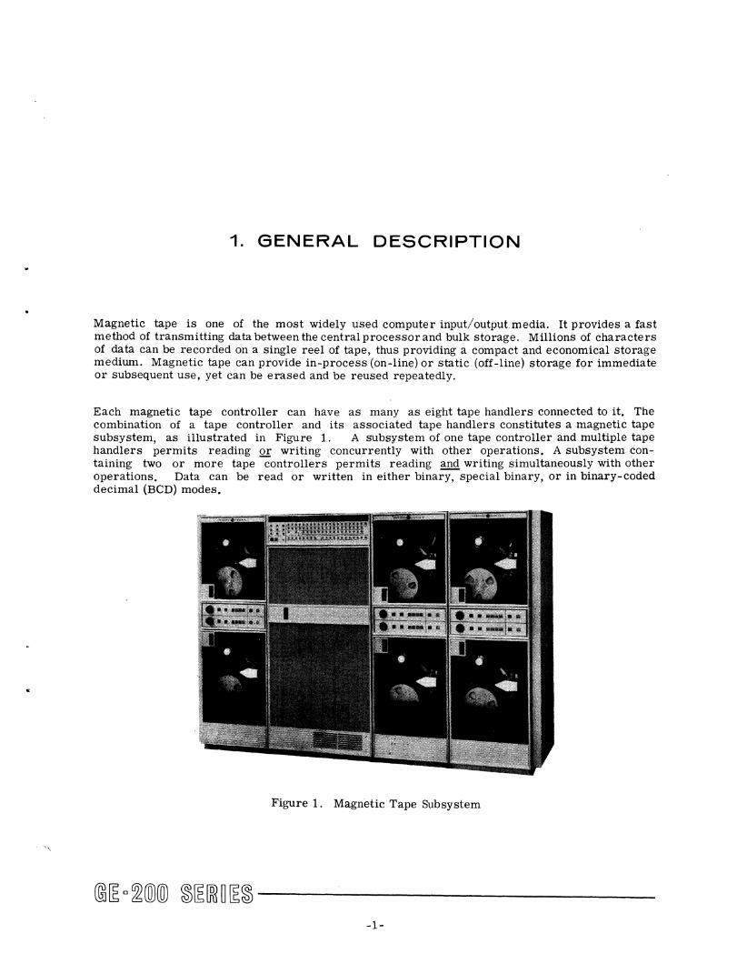
Each magnetic tape controller can have as many as eight tape handlers connected to it. The combination of a tape controller and its associated tape handlers constitutes a magnetic tape subsystem, as illustrated in Figure 1. A subsystem of one tape controller and multiple tape handlers permits reading Q! writing concurrently with other operations. A subsystem containing two or more tape controllers permits reading and writing simultaneously with other operations. Data can be read or written in either binary, special binary, or in binary-coded decimal (BCD) modes.
Figure 1. Magnetic Tape Subsystem
-1-
The maximum number of magnetic tape controllers which can be used in anyone system varies with the type of central processor. The GE-200 Bank Transit System can have one model 680 or one model 690 subsystem. The GE-215 can have one model 680 or 690. The GE-225 can have eight subsystems of either model. This means that a maximum of 64 tape handlers can be used with one central processor. The GE-235 can have a maximum of seven magnetic tape subsystems of either model, a maximum of 56 tape handlers.
Programs written for one of the compatible General Electric information proce~sing systems-the GE-200, 215, 225, and 235--can be readily used with any other of the systems using the same input! output equipment.
SUBSYSTEM MODELS
Magnetic tape models 680 and 690 appear to be identical, their operation is identical (with the exception of the use of one switch), and their programming is identical. The subsystems differ in their internal electronic circuitry which results in a considerable difference in the reading and writing speeds.
Model 680 (16 kc)
Model 680 reads tape and writes on tape with a density of 200 bits or characters per inch. The tape moves forward at the rate of 75 inches per second. Therefore, the transfer rate is:
200 x 75 = 15,000 characters per second
Model 690 (15/41.6 kc)
Model 690 permits the user to choose between two tape denSities and tape transfer rates. Tape moves forward at the rate of 75 inches per second. Therefore, the transfer rate with the 200 bits per inch denSity is the same as that with model 680, or 15,000 characters per second. The transfer rate with the tape of 555.5 bits per inch is:
555.5 x 75 = 41,660 characters per second
MAGNETIC TAPE CONTROLLER
The controller is the link between the central processor and magnetic tape handlers. It contains the circuits for the selection and control of the tape handler and for data transfer between tape handlers and memory. It also contains its own power unit. Each controller operates through a controller selector channel and is addressed by its channel number. It is customary to use a low numbered (high priority) channel. The most frequently used number is 1. Memory access is requested whenever the tape controller either has data for memory or is requesting data from memory. Aside from these interruptions, the central processor memory is released.
@~ D~(Q)(Q) ~~[ffi~~~ ------------2-
•
The tape controller selects and controls the starting and stopping of the tape handlers, forms and/or detects the end-of-record or end-of-file gaps, and sets memory interrupt circuits. Hardware design does not permit simultaneous read and write operations with only one controller.
Error-Checking Circuitry
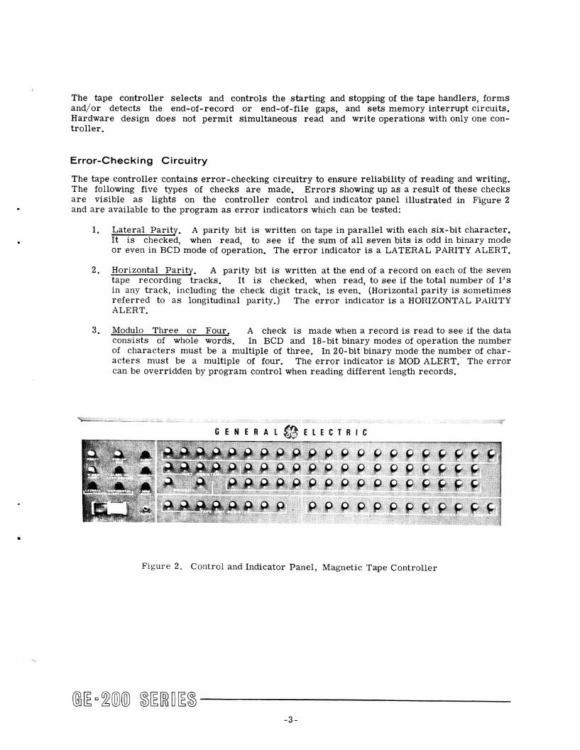
The tape controller contains error-checking circuitry to ensure reliability of reading and writing. The following five types of checks are made. Errors showing up as a result of these checks are visible as lights on the controller control and indicator panel illustrated in Figure 2 and are available to the program as error indicators which can be tested:
1. Lateral Parity. A parity bit is written on tape in parallel with each six-bit character. It is checked, when read, to see if the sum of all seven bits is odd in binary mode or even in BCD mode of operation. The error indicator is a LATERAL PARITY ALERT.
2. Horizontal Parity. A parity bit is written at the end of a record on each of the seven tape recording tracks. It is checked, when read, to see if the total number of l's in any track, including the check digit track, is even. (Horizontal parity is sometimes referred to as longitudinal parity.) The error indicator is a HORIZONTAL PARITY ALERT.
3. Modulo Three or Four. A check is made when a record is read to see if the data consists of whole words. In BCD and IS-bit binary modes of operation the number of characters must be a multiple of three. In 20-bit binary mode the number of characters must be a multiple of four. The error indicator is MOD ALERT. The error can be overridden by program control when reading different length records .
Figure 2. Control and Indicator Panel, Magnetic Tape Controller
-3-
4. Controller Input/Output Register Exhaust or Overflow. The tape controller has the capacity to store two complete memory words. If at any time during read or write operations the controller requests a memory cycle and is not granted access to memory before its input/output register is either exhausted or overflowed, an error results. Either of these conditions turns on the MEMORY ALERT indicator on the controller display panel.
5. Controller Input/Output Register Parity Error. Before information is transferred to the controller from memory, a parity bit is generated on the whole word. This parity bit is checked in the controller input/output register before each word of data is written on tape. Conversely, a parity bit is generated for the word to be transferred to memory from the controller input/output register. This parity bit is used to check the transmission of information between the controller and memory. A parity error turns on the N REG ALERT light on the controller display panel.
These errors are recoverable, meaning that the program does not stop, for the programmer can cause the program to repeat the whole read or write cycle until the error is corrected. Whenever the controller is reselected, the error lights go out.
Control and Indicator Panel
Five of the indicators on this panel have just been described under the heading of error checking circuitry. Four other indicators are:
1. ALERT ON LAST RECORD. This indicator is illuminated when any of the above five types of recoverable errors occurred in the last record read or written.
2. READY. This indicator is illuminated if controller power is on. (It does not actually mean that the controller is ready for the central processor to address it; for example, tapes may not be threaded.)
3. ALERT HALT, This indicator is illuminated under the following error conditions (in every case the computer halts and operator intervention is required to correct the condition):
a. A parity error on instruction words 2 and 3 during the transfer of these words.
b. Addressing a tape transport while it is rewinding.
c. Attempting to address a tape which has not been manually selected.
d. Any detectable malfunction of the tape handler such as handler power not on, REMOTE/LOCAL switch set to LOCAL, or no tape threaded.
e. Specifying a tape handler logical address for which there is more than one unit selected.
@~ o~(Q)(Q) ~~[ffi~~~ -----------, -4-
..
f. Attempting to write on a tape which does not have a write-permit ring.
g. Attempting to perform a read backward instruction (RBB, RBD, or RBS) when the tape is in the rewound condition and initially positioned at the load point marker.
4. END OF FILE. This indicator is illuminated after an end-of-file has been reached on tape while reading. It remains lit until cleared manually by the CLEAR button or until the next SEL instruction is given.
The functions of the indicators just described are summarized in Figure 20, and the descriptions of the use of these indicators under error conditions are summarized in Figure 28.
The controller contains registers and counters for use in storage and timing of information as it passes in either direction between tape and memory. Information in some of these registers and counters can be seen on the control and indicator panel, where it is displayed mainly for use by service engineers. Although it is not necessary to use these indicators in routine operations, the information they display is helpful in understanding what causes processing to stop under certain error conditions. All of these indicators are white lights.
N REGISTER. Indicates the data stored temporarily while in transit (in either direction) between a tape handler and the central processor. Shown are the 20 data bits and a parity bit.
INST. REGISTER, The five bits of this register indicate the type of instruction to be executed, The operator should be familiar with the magnetic tape programming instructions and know the octal and binary representations of their operation codes,
ADDRESS REGISTER, Indicates the starting address in memory for reading or writing.
PRIORITY I and 2, Indicates two phases of a time cycle, the first of which is the time during which the controller is requesting access and the second is the time when it is actually granted access to the central processor.
WORD COUNTER, Indicates the counting of words written or read from magnetic tape, Initially, the counter is preset to the 2's complement of the number of words to be written or read as a result of a single instruction, The visible count, therefore, increases rather than decreases as the instruction is executed,
CHARACTER COUNTER, Indicates the character count in a word as it is read or written on magnetic tape, Each new instruction transferred to the controller from the central processor resets the counter to zero, The count goes to three if in BCD or 18-bit (special) binary mode and to four if in 20-bit binary mode of operation, The function of the character counter is to control the number of characters transferred to and from tape and to step the word counter after the proper number of characters has been transferred,
T APE UNIT REGISTER, Indicates the rotary selector switch setting of the tape unit in use.
-5-
PROGRAM COUNTER, Indicates the place in a sequence of events in the controller's internal control mechanism as it controls the sequence of operation of the tape controller, This will probably never be meaningful to an operator, but it is used by the service engineer,
There are three switches of the pushbutton type on the controller control and indicator panel:
POWER ON switch and indicator, When depressed, this turns on power to the magnetic tape subsystem, and indicates that it is on,
POWER OFF switch, system,
When depressed, this turns off power to the magnetic tape sub-
CLEAR switch, When depressed, this clears the circuitry of all error conditions, and turns off all the error condition indicators on the control and indicator panel,
Optional Buffer
Model 690 can have an optional additional buffer in its controller, This buffer is known as the "magnetiC tape buffer" and holds an additional word while information is in transit in either direction between the tape unit and the central processor, The buffer doubles the length of time the tape controller can wait for priority, permitting the magnetic tape subsystem to be assigned a lower order of priority,
When a system has two 41.6 kc magnetic tape controllers, each controller should have the optional buffer to take full advantage of the ability of the system to read and write simultaneously with other controller selector input! output devices, Fully buffered equipment facilitates expansion of system operations,
MAGNETIC TAPE HANDLER
General Description
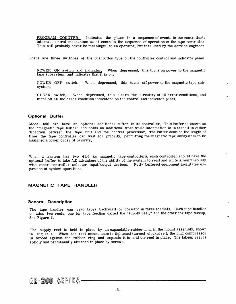
The tape handler can read tapes backward or forward in three formats, Each tape handler contains two reels, one for tape feeding called the "supply reel," and the other for tape takeup, See Figure 3.
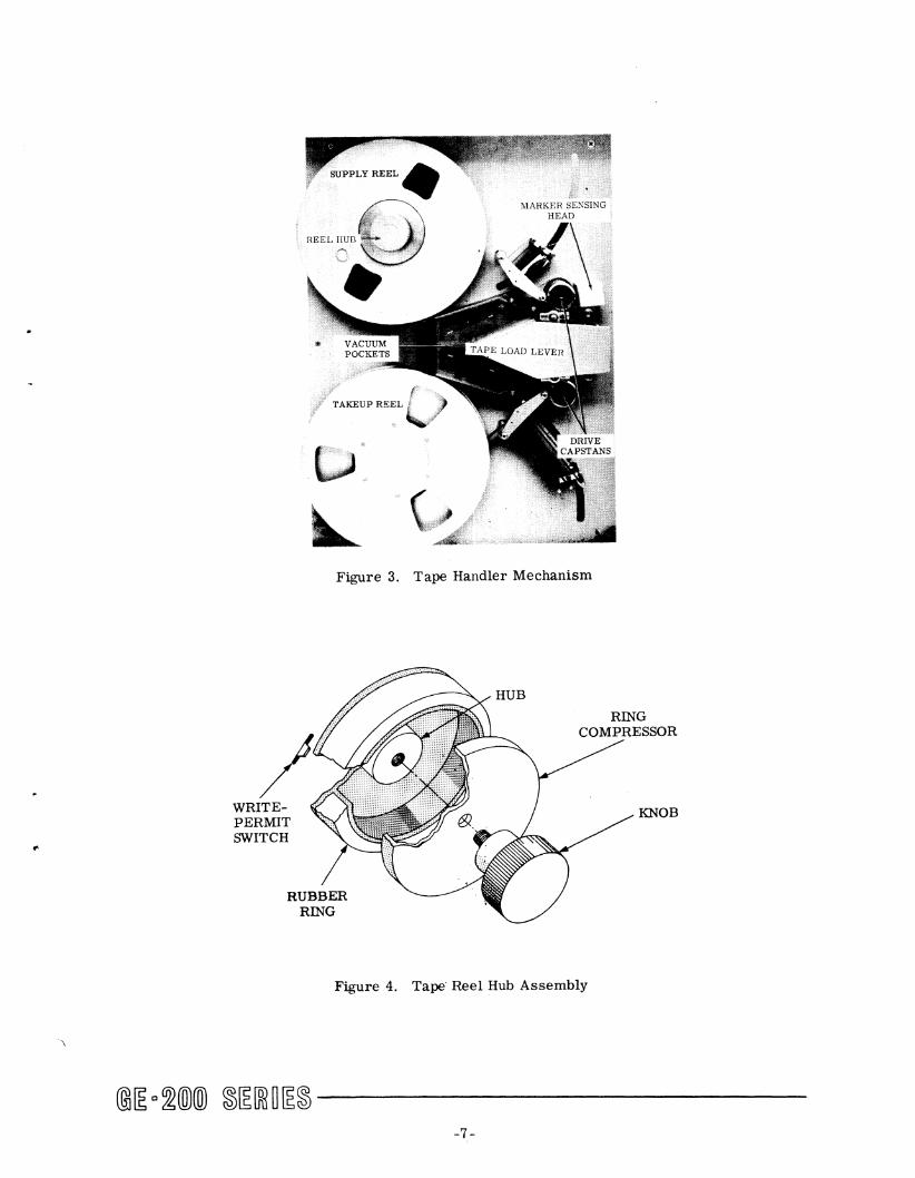
The supply reel is held in place by an expandable rubber ring in the mount assembly, shown in Figure 4. When the reel mount knob is tightened (turned clockwise), the ring compressor is forced against the rubber ring and expands it to hold the reel in place. The takeup reel is solidly and permanently attached in place by screws.
-6-
..
WRITEPERMIT SWITCH
REEL HUB
f .. TAKEUP REEL t. l ,.7'
Figure 3. Tape Handler Mechanism
KNOB
Figure 4. Tape Reel Hub Assembly
-7 -

The tape handler mechanism drives the tape past separate read and write heads. See Figure 5. Tape is threaded aroWld tape guides, and between the capstans and their respective drive rollers. Vacuum pockets perform that fWlction of holding the tape even and smooth as it passes the read and write heads. When the handler power is on, the capstans rotate continuously in opposite directions (the top one rotates clockwise) and are always ready to drive the tape when a drive roller forces the tape against one of them. Tape moves forward when the drive roller is against the forward capstand and backward when the drive roller is against the reverse capstan. Two sensing cells in the photosensor are positioned to detect the beginning-of-tape and end-oftape markers.
I Each tape handler has a provislOn to move tape forward at a rate of 75 inches per second or to rewind at 150 inches per second. When tape moves backward as a result of a read backward instruction, its speed is 75 inches per second. The tape load lever acts on a thread switch so that when the lever is opened, the tape tension arms are pulled open and a brake holding the reel hubs is released to allow the reels to turn freely. When the load lever is closed, the thread switch is released to the normal position, and the tape tension arms return to a null position.
Figure 5. Tape Handler Mechanism Parts
@[E o~@@ ~[E[ffi ~[E~ --------------8-
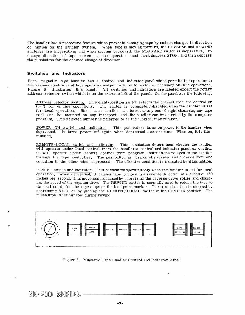
The handler has a protective feature which prevents damaging tape by sudden changes in direction of motion on the handler system. When tape is moving forward, the REVERSE and REWIND switches are inoperative; and when moving backward, the FORWARD switch is inoperative. To change direction of tape movement, the operator must first depress STOP, and then depress the pushbutton for the desired change of direction.
Switches and Indicators
Each magnetic tape handler has a control and indicator panel which permits the operator to see various conditions of tape operation and permits him to perform necessary off-line operations. Figure 6 illustrates this panel. All switches and indicators are labeled except the rotary address selector switch which is on the extreme left of the panel. On the panel are the following:
Address Selector switch. This eight-position switch selects the channel from the controller (0-7) for on-line operations. The switch is completely disabled when the handler is set for local operation. Since each handler can be set to anyone of eight channels, any tape reel can be mounted on any transport, and the handler can be selected QY the computer program. This selected number is referred to as the "logical tape number."
POWER ON switch and indicator. This pushbutton turns on power to the handler when depressed. It turns power off again when depressed a second time. When on, it is illuminated.
REMOTE/LOCAL switch and indicator. This pushbutton determines whether the handler will operate under local control from the handler's control and indicator panel or whether it will operate under remote control from program instructions relayed to the handler through the tape controller. The pushbutton is horizontally divided and changes from one condition to the other when depressed. The effective condition is indicated by illumination.
REWIND switch and indicator. This pushbutton operates only when the handler is set for local operation. When depressed, it causes tape to move in a reverse direction at a speed of 150 inches per second. This movement is caused by energizing the reverse drive roller and changing the speed of the capstan drive. The REWIND switch is normally used to return the tape to its load point, for the tape stops on the load pOint marker. The rewind motion is stopped by depressing STOP or by placing the REMOTE/LOCAL switch in the REMOTE pOSition. The p'lshbutton is illuminated during rewind.
1-
! (00
1'3 SOWER ~MCIl1l , ON LOCAL
I , / 4 ,--, WRITE INH La DEN
REWIND REVERSE FORWARD STOP ADDR HI DEN
- .----------------________________ ----1
Figure 6. Magnetic Tape Handler Control and Indicator Panel
@[E 0 ;92WXID ~[E[ffi ~ ~~ --------------9-

REVERSE switch and indicatorA This pushbutton operates only when the handler is set for local operation. When depressed, it energizes the reverse drive roller and causes tape to move in a reverse direction at a speed of 75 inches per second until it is stopped by the sensing of the load-point marker. The motion is also stopped by depressing STOP or by placing the REMOTE/LOCAL switch in the REMOTE position. The pushbutton is illuminated during reverse movement of tape.
FORWARD switch and indicator. This pushbutton, when depressed, energizes the forward drive roller and therefore causes forward movement of tape when the handler is in the local state. Tape will continue moving until the STOP pushbutton is depressed, the trailer foil is detected, or the REMOTE/LOCAL switch is placed in the REMOTE position. The pushbutton is illuminated during forward movement of tape.
STOP switch. This pushbutton operates only when the handler is set for local operation. When depressed, it stops all local movement of the tape handler. The switch must be used every time direction of tape movement is changed. It is not an indicator.
ADDR/WRITE INH indicator. This indicator is split horizontally through the center. The top half (ADDR) is illuminated under program control whenever the magnetic tape controller is addressed by the central processor for a read or write operation. The bottom half (WRITE INH) is illuminated when writing is inhibited and only reading is possible, meaning that the write-permit ring is not on the supply reel.
HI DEN/LO DEN switch and indicator. On model 690, this switch determines the selection of densitY for reading or writing tape. The density is either 555.5 bits per inch (HI DEN 41.6 kc) or 200 bits per inch (LO DEN, 15 kc). The pushbutton changes density from one to another when depressed, and is horizontally divided so that the density selected is illuminated. On model 680, the switch is disabled because the handler operates on low density only.
MAGNETIC TAPE
Magnetic tape may be used as on-line storage during a computer run and may also be used as off-line storage to retain information as a file for subsequent related computer runs.
Physical Characteristics
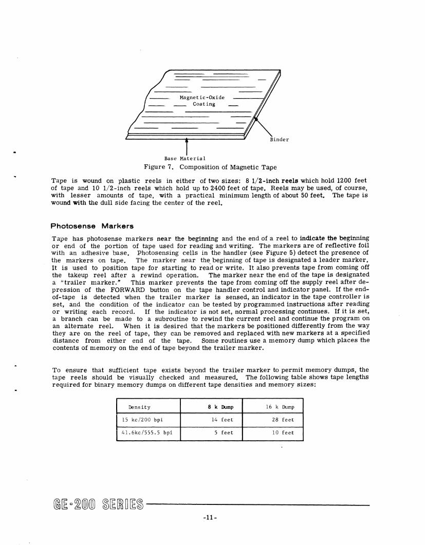
The General Electric information processing systems use heavy-duty, hard-binder tape. (See Figure 7.) The functional characteristics of this tape are compatible with those of the system itself, so this tape and only this tape must be used with the GE-200, 215, 225, and 235 information processing systems. The tape is 0.5 inch wide and 0.0019 inch thick. It has a polyester base (the shiny side) and an oxide coating (the dull side).
Another feature of the tape for the GE-200, 215, 225, and 235 computer systems is its high conductivity. This minimizes the static charge commonly experienced with magnetic tape, and consequently reduces the collection of dust and other foreign matter on the tape.
-10-
Magnetic-Oxide __ Coating
Base Material
Figure 7. Composition of Magnetic Tape
Tape is wound on plastic reels in either of two sizes: 8 1/2-inch reels which hold 1200 feet of tape and 10 1/2-inch reels which hold up to 2400 feet of tape. Reels may be used, of course, with lesser amounts of tape, with a practical minimum length of about 50 feet. The tape is wound with the dull side facing the center of the reel.
Photosense Markers
Tape has photosense markers near the beginning and the end of a reel to indicate the beginning or end of the portion of tape used for reading and writing. The markers are of reflective foil with an adhesive base. Photosensing cells in the handler (see Figure 5) detect the presence of the markers on tape. The marker near the_beginning of tape is deSignated a leader marker. It is used to position tape for starting to read or write. It also prevents tape from coming off the takeup reel after a rewind operation. The marker near the end of the tape is designated a "trailer marker." This marker prevents the tape from coming off the supply reel after depression of the FORWARD button on the tape handler control and indicator panel. If the endof-tape is detected when the trailer marker is sensed, an indicator in the tape controller is set, and the condition of the indicator can be tested by programmed instructions after reading or writing each record. If the indicator is not set, normal processing continues. If it is set, a branch can be made to a subroutine to rewind the current reel and continue the program on an alternate reel. When it is desired that the markers be positioned differently from the way they are on the reel of tape, they can be removed and replaced with new markers at a specified distance from either end of the tape. Some routines use a memory dump which places the contents of memory on the end of tape beyond the trailer marker.
To ensure that sufficient tape exists beyond the trailer marker to permit memory dumps, the tape reels should be visually checked and measured. The following table shows tape lengths required for binary memory dumps on different tape densities and memory sizes:
Density 8 k Dump 16 k Dump
15 kc/200 bpi 14 feet 28 feet
41.6kc/555.5 bpi 5 feet 10 feet
@~ o~ill)(ID ~~[ffi~~~ ------------11-
Both 1200 foot and 2400 foot reels of tape initially have the load point marker positioned 10 to 15 feet from the beginning of tape. The trailer marker is initially positioned 14 to 19 feet from the end of tape on 1200 foot reels and 100 feet from the end on 2400 foot reels.
Tape Formats
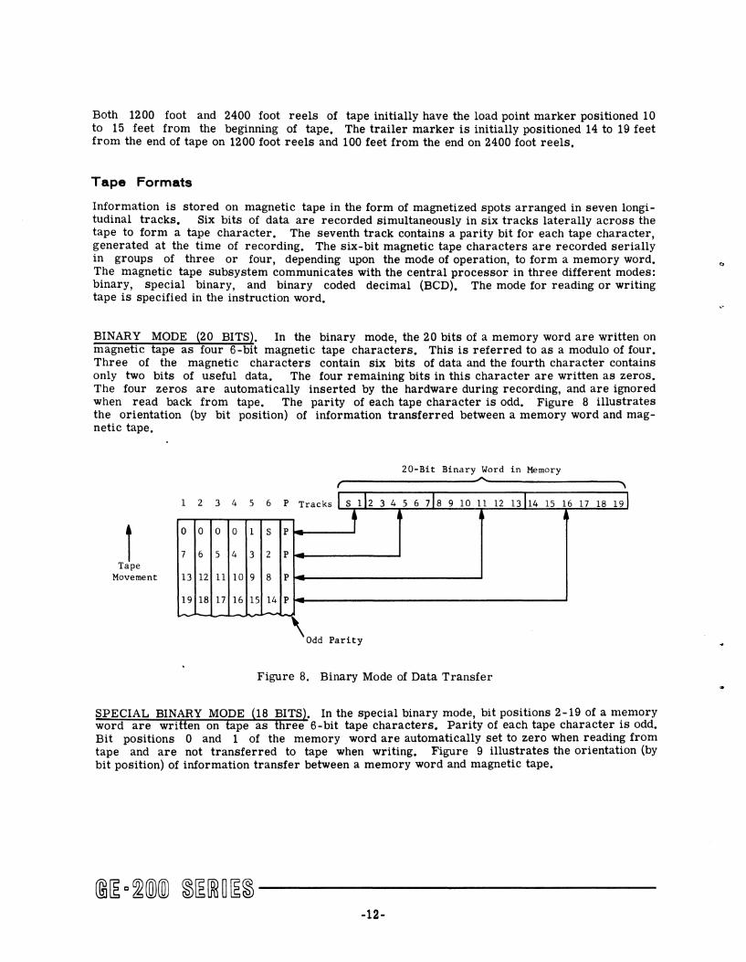
Information is stored on magnetic tape in the form of magnetized spots arranged in seven longitudinal tracks. Six bits of data are recorded simultaneously in six tracks laterally across the tape to form a tape character. The seventh track contains a parity bit for each tape character, generated at the time of recording. The six-bit magnetic tape characters are recorded serially in groups of three or four, depending upon the mode of operation, to form a memory word. The magnetic tape subsystem communicates with the central processor in three different modes: binary, special binary, and binary coded decimal (BCD). The mode for reading or writing tape is speCified in the instruction word.
BINARY MODE (20 BITS). In the binary mode, the 20 bits of a memory word are written on magnetic tape as four 6-bit magnetic tape characters. This is referred to as a modulo of four. Three of the magnetic characters contain six bits of data and the fourth character contains only two bits of useful data. The four remaining bits in this character are written as zeros. The four zeros are automatically inserted by the hardware during recording, and are ignored when read back from tape. The parity of each tape character is odd. Figure 8 illustrates the orientation (by bit position) of information transferred between a memory word and magnetic tape.
20-Bit Binary Word in Memory
r'------------------~",------------------~, 1 2 3 4 5 6 P Tracks L S 112 3 4 5 6 718 9 10 11 12 13114 15 16 17 18 191
f ,
0 0 0 0 1 S P
7 6 5 4 3 2 P Tape
Movement 13 12 11 10 9 8 P
19 18 17 16 15 14 P
Odd Parity
Figure 8. Binary Mode of Data Transfer
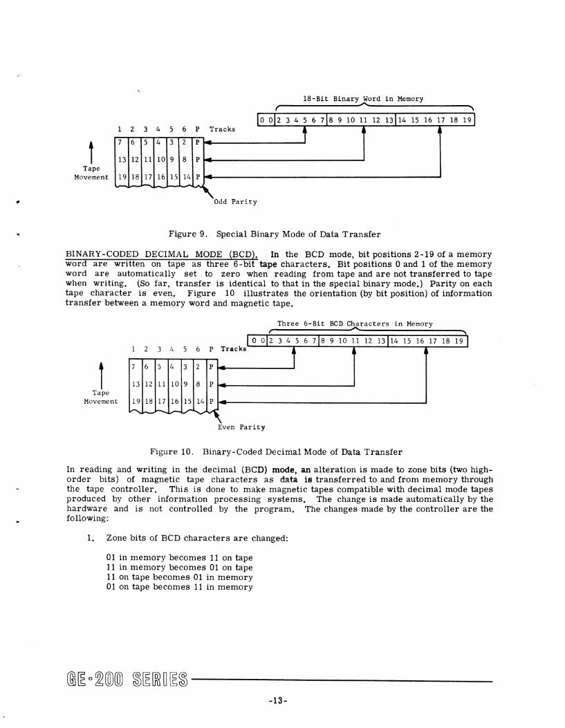
SPECIAL BINARY MODE (18 BITS). In the special binary mode, bit positions 2-19 of a memory word are written on tape as three 6-bit tape characters. Parity of each tape character is odd. Bit pOSitions 0 and 1 of the memory word are automatically set to zero when reading from tape and are not transferred to tape when writing. Figure 9 illustrates the orientation (by bit position) of information transfer between a memory word and magnetic tape.
-12-
r 18-Bit Binary~ord in Memory
Lo 012 345 6 718 9 10 11 12 13114 15 16 17 18 19J 1 2 3 4 5 6 P Tracks , I
7 6 5 4 3 2 P
13 12 11 10 9 8 P Tape
Movement 19 18 17 16 15 14 P
Odd Panty
Figure 9. Special Binary Mode of Data Transfer
BINARY-CODED DECIMAL MODE (BCD). In the BCD mode, bit positions 2-19 of a memory word are written on tape as three 6-bit tape characters. Bit positions 0 and 1 of the memory word are automatically set to zero when reading from tape and are not transferred to tape when writing. (So far, transfer is identical to that in the special binary mode.) Parity on each tape character is even. Figure 10 illustrates the orientation (by bit position) of information transfer between a memory word and magnetic tape.
I - , Three 6-Bit BCD Characters in Memory
1
L 0 01 2 345 6 718 9 10 11 12 13114 15 16 17 18 19 I 1 2 3 4 5 6 P Tracks
i 7 6 5 4 3 2 P
13 12 11 10 9 8 P Tape
Movement 19 18 17 16 15 14 P t...... _L- ~~~
Even Parity
Figure 10. Binary-Coded Decimal Mode of Data Transfer
In reading and writing in the decimal (BCD) mode, an alteration is made to zone bits (two highorder bits) of magnetic tape characters as data is transferred to and from memory through the tape controller. This is done to make magnetic tapes compatible with decimal mode tapes produced by other information processing systems. The change is made automatically by the hardware and is not controlled by the program. The changes made by the controller are the following:
1. Zone bits of BCD characters are changed:
01 in memory becomes 11 on tape 11 in memory becomes 01 on tape 11 on tape becomes 01 in memory 01 on tape becomes 11 in memory
-13-

2. BCD zero is changed
000000 in memory becomes 001010 on tape 001010 on tape becomes 000000 in memory
It should be noted that a BCD memory octal 12 is written on tape as a 12; but, because of the "zero" change, it is read back into memory as a zero.
BCD MEMORY __ ...... .. (OCTAL)
00 12
BCD MAGNETIC TAPE (OCTAL)
12 12
BCD MEMORY .. (OCTAL)
00 00
Figure 11 is an example of an actual BCD character transfer from memory to magnetic tape. Notice that the zone bits of the percent chara~ter were altered from 11 to 01 in the transfer and that a parity bit was added where necessary.
Three 6-Bit BCD Characters in Memory r --------~\
S 1 2 3 4 5 6 7 8 9 10 11 12 13 14 15 16 17 18 19
f Tape
1 2 3 4 5 6 P Tracks 1 , ~
0 0 1 1 1 0 1 Bit Positions 2 through 7
1 1 1 0 0 0 1 Bit Pos it ions 14 through 19
7. 6 1 0 I 1 1 1 0 0 10 001 1 o 0 1
Movement 0 1 1 0 0 0 0 Bit Positions 8 through 13
........... -Even Parit y
Figure 11. Binary-Coded Decimal Character Transfer to Magnetic Tape
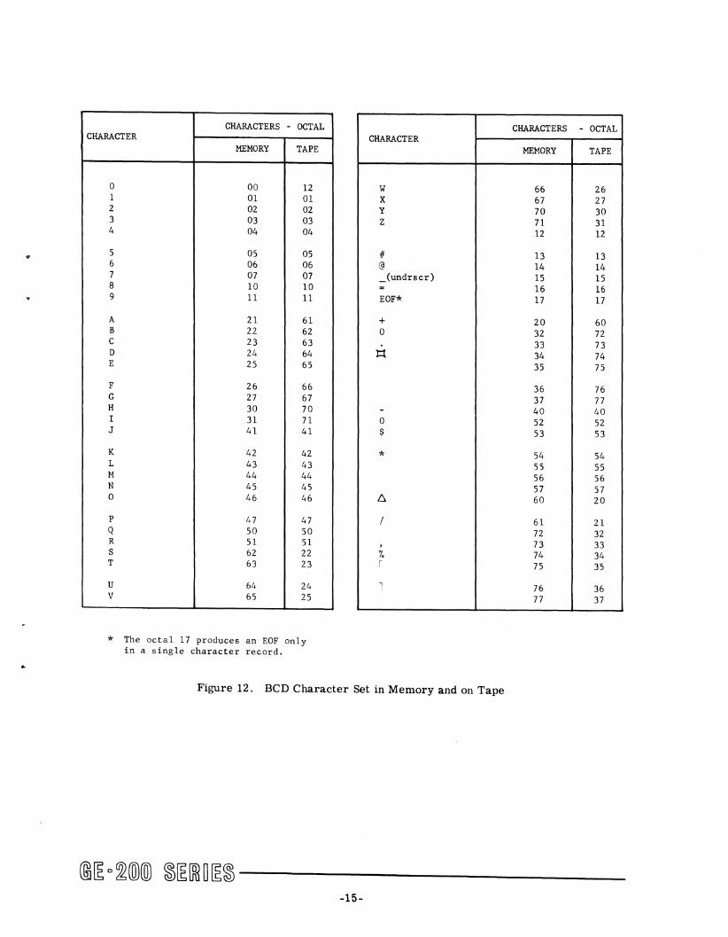
The octal equivalent of the BCD character set as it appears in memory and on tape is shown in Figure 12.
Figure 13 illustrates the recording of BCD characters on tape. The configuration is that of the "Tape" column of Figure 12, to which parity bits have been added to result in even parity.
-14-
"
..
CHARACTERS - OCTAL CHARACTER
MEMORY TAPE
0 00 12 1 01 01 2 02 02 3 03 03 4 04 04
5 05 05 6 06 06 7 07 07 8 10 10 9 11 11
A 21 61 B 22 62 C 23 63 D 24 64 E 25 65
F 26 66 G 27 67 H 30 70 I 31 71 J 41 41
K 42 42 L 43 43 M 44 44 N 45 45 0 46 46
P 47 47 Q 50 50 R 51 51 S 62 22 T 63 23
U 64 24 V 65 25
* The octal 17 produces an EOF only in a single character record.
CHARACTER
W X Y Z
if @
_(undrscr) = EOF*
+ 0
14
-0 $
*
6
/
, /, , ,
Figure 12. BCD Character Set in Memory and on Tape
CHARACTERS - OCTAL
MEMORY TAPE
66 26 67 27 70 30 71 31 12 12
13 13 14 14 15 15 16 16 17 17
20 60 32 72 33 73 34 74 35 75
36 76 37 77 40 40 52 52 53 53
54 54 55 55 56 56 57 57 60 20
61 21 72 32 73 33 74 34 75 35
76 36 77 37
@[E c~@@ ~[E[ffi~[E~ ------____ _ -15-

Track
Parity P Zones G
Numerics {~
0123456789 ABCDEFGHIJKLKNOPQRSTUVWXYZ
1 1 1 1 11 1 11 1 11 1 1 11 111111111111111111 111111111 11111111
1 1 1 1 1 1 I 1 1 1 1 1 1 1 1 1 1111 1111
1 1 1 1 1 1 1 1 11 11 11 11 1 1 1 1 11 1 1 1 1
+-A/#@ -.$*,7.[J
1 I 1 1 1 1 1
I 1 1 1 1 1 1
1 1 1 1
11111111111 III 1 III
1 1 1 1 1 1 1 1
Figure 13. BCD Characters on Magnetic Tape
MIXED DATA MODES. When core storage contains information in both decimal and binary form, writing and reading of this data to and from magnetic tape must be done in the binary mode so that all twenty bits of each memory word are transferred. This means, however, that each BCD memory word is placed on tape as four 6-bit characters instead of 3 characters. This fourth character on tape contains meaningless information which is of no significant value.
Figure 14 shows a BCD memory word written on tape in the binary mode. It is written as four 6-blt tape characters with odd parity.
Three 6-Bit BCD Char~cters in Memory , ...... , S 1 2 3 4 5 6 7 8 9 10 11 12 13 14 15 )6 17 18 19
10 o 11 1 1 1 0 01 0 0 0 1 1 1 10 0 0 1 1 0
123456 T k
r Tape
P rae s y \Y \7/ ,6
o 0 o 0 001
o 0 1 1 1 1 1
Movement 1 1 1 0 o 0 0
o 1 1 0 001 to.. Odd Panty
Figure 14. BCD Memory-to-Tape Transfer in Binary Mode
TAPE RECORDS AND FILES. Data is recorded on magnetic tape in groups of words called physical records (sometimes called blocks). It must be noted that a physical record is not the same as a data record. A data record is an item of a given length, such as a logical record (for example, pay number). A physical record is the physical section of tape between two gaps of erased portions of tape. The length of the physical record may be predetermined by the programmer, and usually includes several data (logical) records. The minimum limit for a logical record length is one word and the maximum hmit is equal to the size of the memory. A larger grouping of data on tape is designated a file. ·T.he file is an accumulation of related records, and may be even longer than one reel of tape.
@~ o~(o)(ID ~~[ffi~~~ ------------16-
..
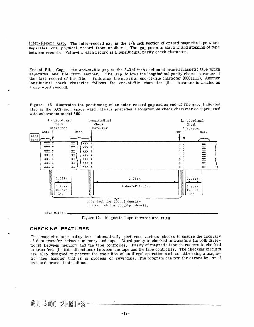
Inter-Record Gap. The inter-record gap is the 3/4 inch section of erased magnetic tape which separates one physical record from another. The gap permits starting and stopping of tape between records. Following each record is a longitudinal parity check character.
End-of-File Gap. The end-of-file gap is the 3-3/4 inch section of erased magnetic tape which separates one file from another. The gap follows the longitudinal parity check character of the last record of the file. Following the gap is an end-of-file character (0001111). Another longitudinal check character follows the end-of-file character (the character is treated as a one-word record).
Figure 15 illustrates the positioning of an inter-record gap and an end-of-file gap. Indicated also is the 0.02-inch space which always precedes a longitudinal check character on tapes used with subsystem model 680.
Longitudinal Check
Character
Longitudinal Check
Character
Data ~ IReadl Hcad~ ~+
XXX X XXX X XXX X XXX X XXX X XXX X XXX X
XX {XXX X XX XXX X XX XXX X XX ( XXX X XX XXX X
XX) \ XXX X XX IXXXX
Longitudinal Check
Character
EOt~ ~ 1 1
1 1 1 1 o 0 o 0 o 0
XX XX XX XX XX XX XX
~--~~------T-J
0.75in ~ .. InterRecord
I-~~-----------En-d-_-:-~_:-:-:n-le--G-a-p------------·~I I :~:::~ Gap
~
0.02 inch for 200bpi density 0.0072 inch for 555.5bpi density
Record Gap
)
Tape Mc)t ion .... ~4---------------------------------------------------------------Figure 15. Magnetic Tape Records and Files
CHECKING FEATURES
The magnetic tape subsystem automatically performs various checks to ensure the accuracy of data transfer between memory and tape. Word parity is checked in transfers (in both directions) between memory and the tape controller. Parity of magnetic tape characters is checked in transfers (in both directions) between the tape and the tape controller. The checking circuits are also designed to prevent the execution of an illegal operation such as addressing a magnetic tape handler that is in process of rewinding. The program can test for errors by use of test-and- branch instructions.
-17 -
Write Check
Each tape handler has two sets of magnetic heads: a read head and a write head. During a read operation only the read head is used. During a write operation (except at end-of-file character) both sets of heads are used. After each tape character is written on tape by the write head, it is read back by the read head and checked for parity. Errors detected in this way can be corrected under program control.
Write-Permit Ring
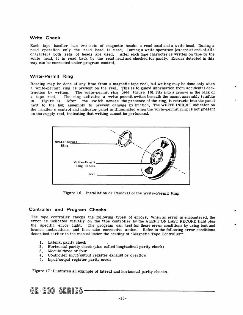
Reading may be done at any time from a magnetic tape reel, but writing may be done only when a write-permit ring is present on the reel. This is to guard information from accidental destruction by writing. The write-permit ring (see Figure 16), fits into a groove in the back of a tape reel. The ring activates a write-permit switch beneath the mount assembly (visible in Figure 4). Mter the switch senses the presence of the ring, it retracts into the panel next to the hub assembly to prevent damage by friction. The WRITE INHIBIT indicator on the handler's control and indicator panel is illuminated when the write-permit ring is not present on the supply reel, indicating that writing cannot be performed.
Write-Pe=.:rm:::i:.:;t~ _______ _ Ring
Write-Permit -----------f-Ring Groove
~el __________ _.~
~~~
Figure 16. Installation or Removal of the Write-Permit Ring
Controller and Program Checks
The tape controller checks the following types of errors. When an error is encountered, the error is indicated visually on the tape controller by the ALERT ON LAST RECORD light plus the specific error light. The program can test for these error conditions by using test and branch instructions, and then take corrective action. Refer to the following error conditions described earlier in the manual under the headi~g of "Magnetic Tape Controller":
1, Lateral parity check 2. Horizontal parity check (also called longitudinal parity check) 3. Modulo three or four 4. Controller input! output register exhaust or overflow 5. Input/ output register parity error
Figure 17 illustrates an example of lateral and horizontal parity checks.
-18-

Track
P 6 5 4 3 2 1
Character
Lateral Parity in Track P for Each Character
I
I I I 1 I I } { I , 1 I I I L I
"\ I I
I )
I I I I I
I I .J
tllltlL G E - 2 2 5
Horizontal Parity Bit for Each Track
Horizontal Check Character
\
Figure 17. Lateral and Horizontal Magnetic Tape Parity (Decimal Mode)
The magnetic tape test-and-branch instructions BCS BIO (Branch on Input/Output Buffer Error) and BCS BIC (Branch on Input/Output Buffer Correct) test for two conditions of the tape controller input/output register. The first condition concerns the granting or not granting of memory requests; a memory request error is indicated by a MEMORY ALERT light on the controller display panel. The other condition concerns a parity error on a data word from memory; a parity error on a data word is indicated by the N REG ALERT light.
Alert Halt Conditions
Certain error conditions and malfunctions which can occur during magnetic tape operations cause the faulty or affected tape handler and its associated controller to halt. These are known as alert halt conditions and cause the ALERT HALT indicator on the controller'S control and indicator panel to glow blue. Manual intervention is required to return the controller and tape handler to operation. The alert halt condition mayor may not cause the central processor to halt. If the alert condition occurs during the transfer of words 1, 2, or 3 to the controller, the central processor also halts. If the condition occurs after the tape handler becomes busy, the central processor continues processing. However, a subsequent attempt to address the halted controller and tape handler (or other handler on that controller) will then halt the central processor. An ALERT HALT condition occurs as a result of:
1. A parity error on instruction words 2 or 3 as these words are transferred from memory to the tape controller.
2. AddreSSing a tape handler that is rewinding.
3. Addres sing a nonexistent tape handler.
4. AddreSSing a tape handler which is one of two units on a controller having the same address.
-19-
5, A detectable malfunction of a tape handler,
6, Giving a write instruction to a tape handler without the write-permit ring on the tape reel,
7, Giving a read backward instruction when the tape is positioned on the leader,
-20-
c
2. PROGRAMMING
FOR MAGNETIC TAPE OPERATIONS
INSTRUCTION FORMAT
All instructions executed by the magnetic tape controller require three memory words. The format for writing these instructions in the General Assembly Program language uses the following conventions:
P controller assigned (controller selector channel number) M memory location (starting) TC code for the specific tape command T tape handler assignment (number 0-7) TT binary configuration of the code for tape handler number N number of words (length of record) Index = address modification locations (0-3)
Each of the two models of magnetic tape subsystems requires the same formats for instruction words.
Instruction Word 1
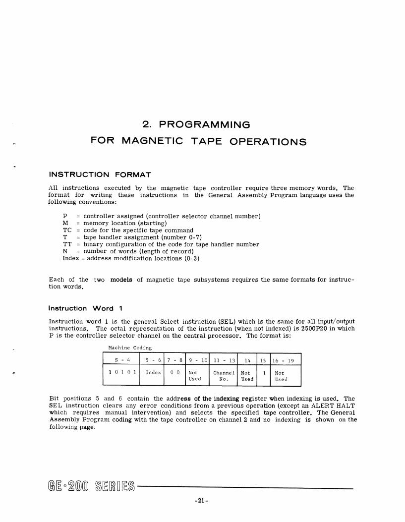
Instruction word 1 is the general Select instruction (SEL) which is the same for all input/output instructions. The octal representation of the instruction (when not indexed) is 2500P20 in which P is the controller selector channel on the central processor. The format is:
Machine Coding
s - 4 5 - 6 7 - 8 9 - 10 11 - 13 14 15 16 - 19
1 o 1 o 1 Index o 0 Not Channel Not 1 Not Used No. Used Used
Bit pOSitions 5 and 6 contain the address of the indexing register when indexing is used. The SEL instruction clears any error conditions from a previous operation (except an ALERT HALT which requires manual intervention) and selects the specified tape controller. The General Assembly Program coding with the tape controller on channel 2 and no indexing is shown on the following page.
-21-

A bi L ssem LV anguage C d' o mg Symbol Opr Operand X
, I 2 I • I • I • I 0 • I • I ,0 "1 '"I "1 '"1'01 17 1 ,. I ,. 20
I S E L 2 )
Instruction Words 2 and 3
Instruction word 2 specifies the tape operation to be performed (Te) and, when the operation is a read or a write, specifies the starting memory address (MMMMM). The memory address is right- justified in the word. The word cannot be indexed.
Instruction word 3 specifies the coded number of the tape handler to be used (TT) and the maximum number of words to be read or written in one record (NNNNN). The number is rightjustified in the word. The word cannot be indexed. The following is the code for the tape handler number:
Handler Number Bits 0-4 Octal Code
0 00001 01 1 00010 02 2 00100 04 3 01000 10 4 10001 21 5 10010 22 6 10100 24 7 11000 30
The assembler generates words 2 and 3 in the following formats:
Instruction Word 2
Machine Coding
I 0-4
I 5 19
TC M M M M M
Instruction Word 3
Machine Coding
1 :41 5 19
N N N N N
-22-
..
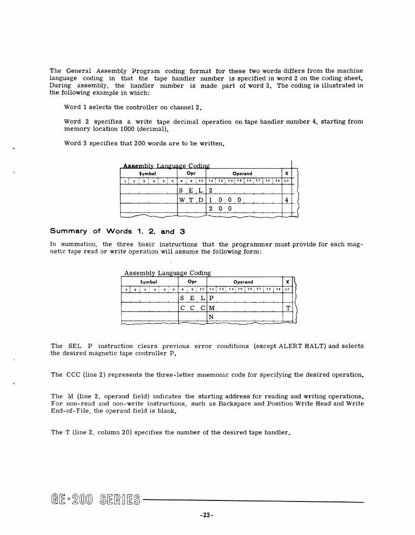
The General Assembly Program coding format for these two words differs from the machine language coding in that the tape handler number is specified in word 2 on the coding sheet. During assembly, the handler number is made part of word 3. The coding is illustrated in the following example in which:
Word 1 selects the controller on channel 2.
Word 2 specifies a write tape decimal operation on tape handler number 4, starting from memory location 1000 (decimal).
Word 3 specifies that 200 words are to be written.
A,u,u'mhlv T ,::InP"11lL!!:e Codin.e: Symbol Opr Operlnd X
,j 2 1'1-L "j " " I • I ,0 '2j "I .. j '"j '"[" [ " i ,. 20
S E L 2
WT D 1 0 0 0 4 2 0 0 )
- -Summary of Words 1, 2, and 3
In summation, the three basic instructions that the programmer must provide for each magnetic tape read or write operation will assume the following form:
A bl L ssem Ly anguage C d' o mg Symbol Opr Operand X
'1 2 1 3 1 - j "i " " \ • I '0 '2j "I '-I '"j '"\"1 ,. i ,. 20
S E L P
C C C M T ) N
The SEL P instruction clears previous error conditions (except ALERT HALT) and selects the desired magnetic tape controller p.
The CCC (line 2) represents the three-letter mnemonic code for specifying the desired operation.
The M (line 2, operand field) indicates the starting address for reading and writing operations. For non-read and non-write instructions, such as Backspace and Position Write Head and Write End-of-File, the operand field is blank.
The T (line 2, column 20) specifies the number of the desired tape handler.
-23-
The N (line 3) specifies the number of words to be read or written. In cases where N must be zero, the third word may be left off the coding sheet (as in Rewind Tape). It is not necessary to leave a blank line on the coding sheet. The assembler then generates the third word with N as zero.
MAGNETIC TAPE INSTRUCTIONS
Programming for 15 kc tape is identical to that for 41.6 kc tape. There is no difference in instructions or in their execution on magnetic tape subsystem models 680 and 690. Tape density selection on model 690 is a physical operation performed by the operator. Programmers' instructions to the operator specify the tape density to be used. Programming is also identical for each of the compatible General Electric Information Processing Systel11s--the GE-200. 215, 225, and 235. If a program needs to know on which system it is being run, the instruction WAI (Who Am I, octal code 2504010, see CPB-374, GE-235 Central Processor Reference Manual) can be used to test for GE-200, 215, 225, or 235. The knowledge may be required for selection of timing loops in programs which are to be used on all of the systems.
Each instruction for magnetic tape operation is explained in paragraphs which follow by use of a specific format. Following the name of the instruction is a heading. Following the heading is a functional description of the execution of the instruction and the results of its execution. For most instructions, an example is then given of its use and its General Assembly Program coding.
Tape Movement Instructions
The heading of a tape movement instruction contains:
1. Symbols for assembly program coding for the second and third words of the instruction.
2. The octal representation of the machine coding for those two words.
Tile single letter T in the heading stands for the tape handler number (the same as the switch setting on the handler). Each of the tape movement instructions must have SEL P as the first word. For convenience, the first word has been assumed and is not shown with the individual instruction descriptions.
Word times, of course, differ depending upon which central processor is used. The actual time in microseconds varies as follows:
System Word Time
GE-200 18 microseconds GE-215 36 microseconds GE-225 18 microseconds GE-235 6 microseconds
-24-
.,.
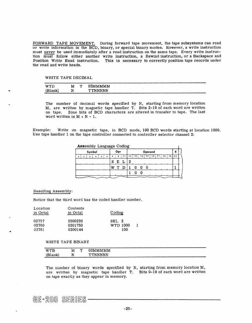
FORWARD TAPE MOVEMENT. During forward tape movement, the tape subsystems can read or write information in the BCD, binary, or special binary modes. However, a write instruction must never be used immediately after a read instruction on the same tape. Every write instruction must follow either another write instruction, a Rewind instruction, or a Backspace and Position Write Head instruction. This is necessary to correctly position tape records under the read and write heads.
WRITE TAPE DECIMAL
WTD (Blank)
M T N
02MMMMM TTNNNNN
The number of decimal words specified by N, starting from memory location M, are written by magnetic tape handler T. Bits 2-19 of each word are written on tape. Zone bits of BCD characters are altered in transfer to tape. The last word written is M + N - 1.
Example: Write on magnetic tape, in BCD mode, 100 BCD words starting at location 1000. Use tape handler 1 on the tape controller connected to controller selector channel 2:
Assembly Language Coding
Symbol Opr Operand
, 1 2 1 • 1 • 1 • 1 • 8 I • i ,0 '21 13 1 "1" I'· i'7 I" I'·
, S E L 2
WT D 1 0 0 1 0 0 - - ~
Resulting Assembly:
Notice that the third word has the coded handler number.
Location in Octal
02757 02760 02761
Contents in Octal
2500220 0201750 0200144
WRITE TAPE BINARY
WTB (Blank)
M T N
03MMMMM TTNNNNN
Coding
SEL 2 WTD 1000
100 1
0
X .~ 20
1
J
The number of binary words specified by N, starting from memory location M, are written by magnetic tape handler T. Bits 0-19 of each word are written on tape exactly as they appear in memory.
-25-
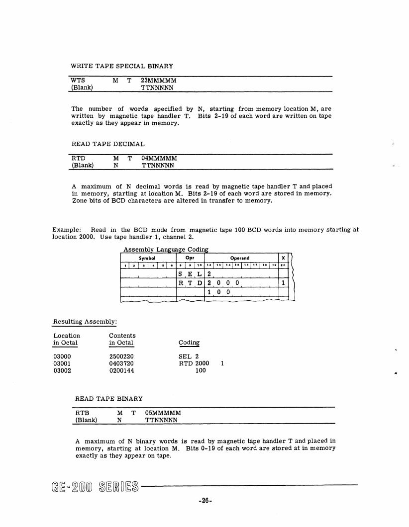
WRITE TAPE SPECIAL BINARY
WTS (Blank)
M T 23MMMMM TTNNNNN
The number of words specified by N, starting from memory location M, are written by magnetic tape handler T. Bits 2-19 of each word are written on tape exactly as they appear in memory.
READ TAPE DECIMAL
RTD (Blank)
M T 04MMMMM N TTNNNNN
A maximum of N decimal words is read by magnetic tape handler T and placed in memory, starting at location M. Bits 2-19 of each word are stored in memory. Zone bits of BCD characters are altered in transfer to memory.
Example: Read in the BCD mode from magnetic tape 100 BCD words into memory starting at location 2000. Use tape handler 1, channel 2.
A bl ssem Ly Language C dO o lUg Symbol Opr Operand
• !2!_!_!_!6 6 i • ['0 '2[ "[ .. j ,"['6['7 [ ,. i , •
Resulting Assembly:
Location in Octal
03000 03001 03002
Contents in Octal
2500220 0403720 0200144
READ TAPE BINARY
RTB (Blank)
M T N
S E L 2 R T D 2
1
SEL 2 RTD 2000
100
05MMMMM TTNNNNN
0 0 0 0 0
1
X 20
1 (
A maximum of N binary words is read by magnetic tape handler T and placed in memory, starting at location M. Bits 0-19 of each word are stored at in memory exactly as they appear on tape.
-26-

..
..
READ TAPE SPECIAL BINARY
RTS (Blank)
M T 25MMMMM N TTNNNNN
A maximum of N words is read by magnetic tape handler T and placed in memory, starting at location M. A data word from tape is stored in bit positions 2-19 of a memory location just as it appears on tape.
WRITE END OF FILE
WEF T 0200000 TTOOOOO
The end-of-file character (0001111) and end-of-file gap are written on tape by magnetic tape handler T.
Example: Write an end-of-file record on tape using tape handler 4, channel 2.
A bl L ssem Ly angw Symbol
,[.\_\_["\0
I
~-Resulting Assembly:
Location in Octal
02000 02001 02002
Contents in Octal
2500220 0200000 2100000
,ge Cdi o Lng Opr
° 1 • 1 10
S E W E
SEL 2 WEF
L F
Operand
12[ '"I 14 j Ie j ,ol" \ IS i I.
2
4
X ~ 20
4
Notice that the assembler has generated the third instruction word. Tape handler 4 is coded in binary as 10001, and in octal as 21.
-27-
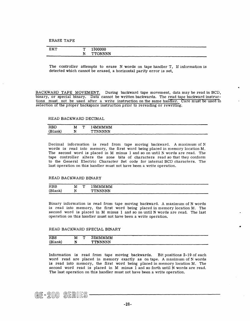
ERASE TAPE
EKT T 1300000 N TTONNNN
The controller attempts to erase N words on tape handler T. If information is detected which cannot be erased, a horizontal parity error is set.
BACKWARD TAPE MOVEMENT. During backward tape movement, data may be read in BCD, binary, or special binary. Data cannot be written backwards. The read tape backward instructions must not be used after a write instruction on the same handler. Care must he used In
selection of the proper backspace instruction prior to rereading or rewriting.
READ BACKWARD DECIMAL
RBD (Blank)
M T N
14MMMMM TTNNNNN
Decimal information is read from tape moving backward. A maximum of N words is read into memory, the first word being placed in memory location M. The second word is placed in M minus 1 and so on until N words are read. The tape controller alters the zone bits of characters read so that they conform to the General Electric Character Set code for internal BCD characters. The last operation on this handler must not have been a write operation.
READ BACKWARD BINARY
RBB (Blank)
M T 15MMMMM N TTNNNNN
Binary information is read from tape moving backward. A maximum of N words is read into memory, the first word being placed in memory location M. The second word is placed in M minus 1 and so on until N words are read. The last operation on this handler must not have been a write operation.
READ BACKWARD SPECIAL BINARY
RBS (Blank)
M T N
35MMMMM TTNNNNN
Information is read from tape moving backwards. Bit positions 2-19 of each word read are placed in memory exactly as on tape. A maximum of N words is read into memory, the first word being placed in memory location M. The second word read is placed in M minus 1 and so forth until N words are read. The last operation on this handler must not have been a write operation.
-28-
•
•
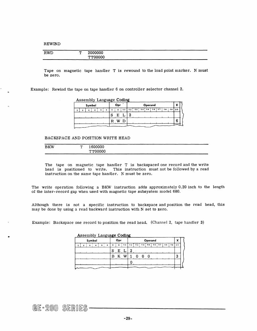
REWIND
RWD T 2000000 TTOOOOO
Tape on magnetic tape handler T is rewound to the load point marker. N must be zero.
Example: Rewind the tape on tape handler 6 on controller selector channel 2.
Assembly Language Coding Symbol Opr Operand X \ • 121.1_1_10 • I • I • 0 '21'"1'-1' 0 1'°1 17 1'.1' • 20
s E L 2 I
RWD 6 ! -BACKSPACE AND POSITION WRITE HEAD
BKW T 1600000 TTOOOOO
The tape on magnetic tape handler T is backspaced one record and the write head is positioned to write. This instruction must not be followed by a read instruction on the same tape handler. N must be zero.
The write operation following a BKW instruction adds approximately 0.20 inch to the length of the inter-record gap when used with magnetic tape subsystem model 680.
Although there is not a specific instruction to backspace and position the read head, this may be done by using a read backward instruction with N set to zero.
Example: Backspace one record to position the read head. (Channel 2, tape handler 3)
A bl ssemly Languap;e C odi 111:
Symbol Opr Operand X
• I 2 I • I - I - I • • I • I '0 '21'31 141 '"1'01. 7 lIB i ,. 20
I S E L 2 B KW 1 0 0 0 3
0 j ~
-29-
Tape Reading Residue Word
During tape reading, the General Assembly Program generates a word called "residue word." The residue word contains information about the number of words in the record previously read. Information contained in the residue word varies according to whether the record length (number of words read) is equal to, greater than, or less than the number of words (N) specified on the coding sheet. The residue word contains information as follows:
1. Reading Tape Forward (any mode)
The residue word is always placed in memory in location M + N where M is the location in memory into which the first word of the record is read and N is the number of words specified on the coding sheet. In memory layout, this extra word location must be allowed for. N + 1 word locations are always required to read N words of tape into memory. In reading tape forward, residue words are as follows:
a. Record length exactly N words--The residue word consists of all zeros.
b. Record length is less than N words--The residue word consists of the 2's complement of the difference between N and the record length (N - record length) and 1. in the sign position.
Example:
M location 0500
N 50 words
Record length = 30 words
Information is stored in locations 0500 - 0529 (0530 - 0549 remain unchanged)
Residue word is in location 0550
Residue word consists of the 2's complement of 248 (which is 50 - 30) and .!. in the sign position
c. Record length is greater than N words--Only N words are read. The residue word consists of the number of excess words (record - N) and 0 in the sign position. The controller remains busy until the entire record has passed the read heads and the inter-record gap is reached.
Example:
M = location 0500
N = 50 words
Record length = 75 words
Information is stored in locations 0500 - 0549
@~ o~(Q)(ID ~~[ffi~~~ ------------30-
..
•
..,
•
Residue word is in location 0550
Residue word consists of 318 (which is 75 - 50) and .Q. in the sign position
The controller remains busy until 75 words have passed the read head
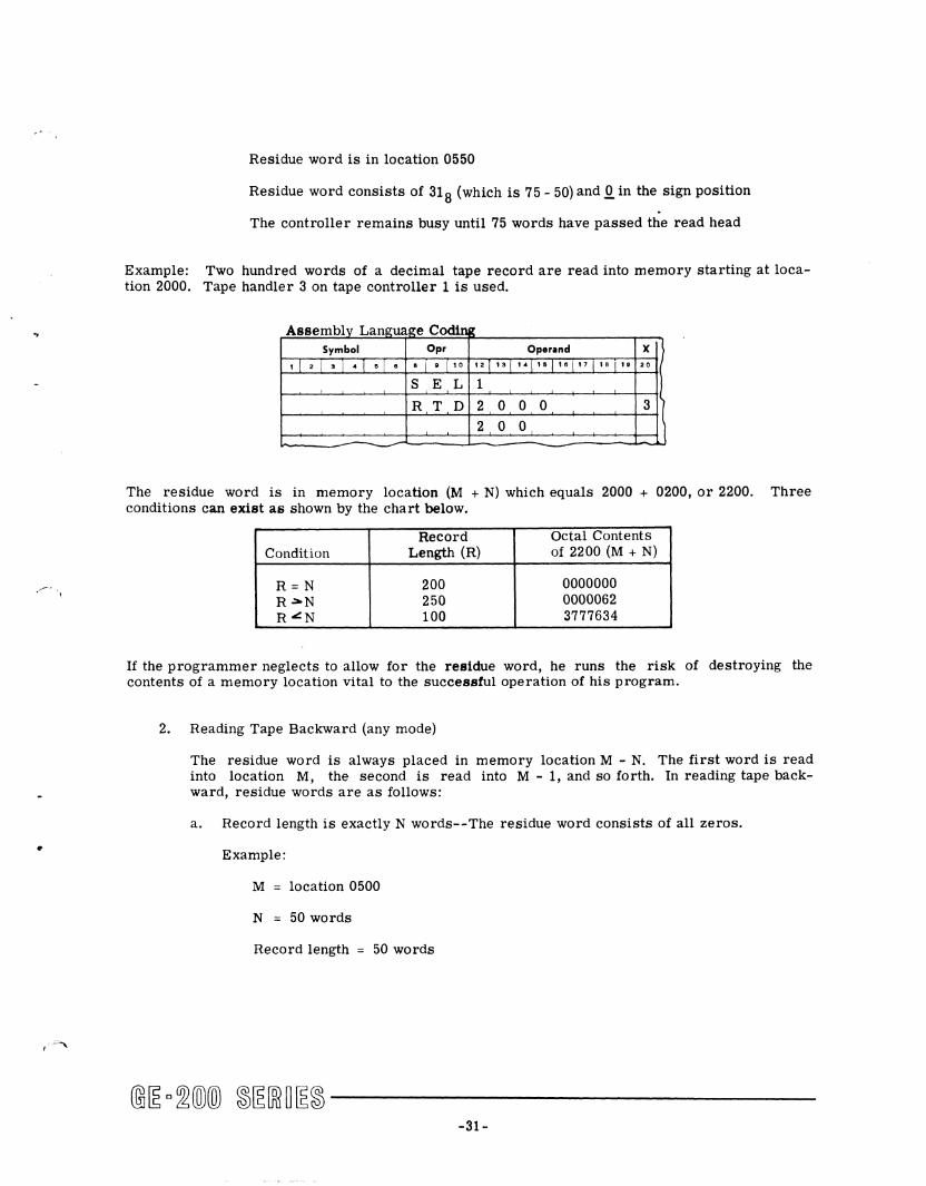
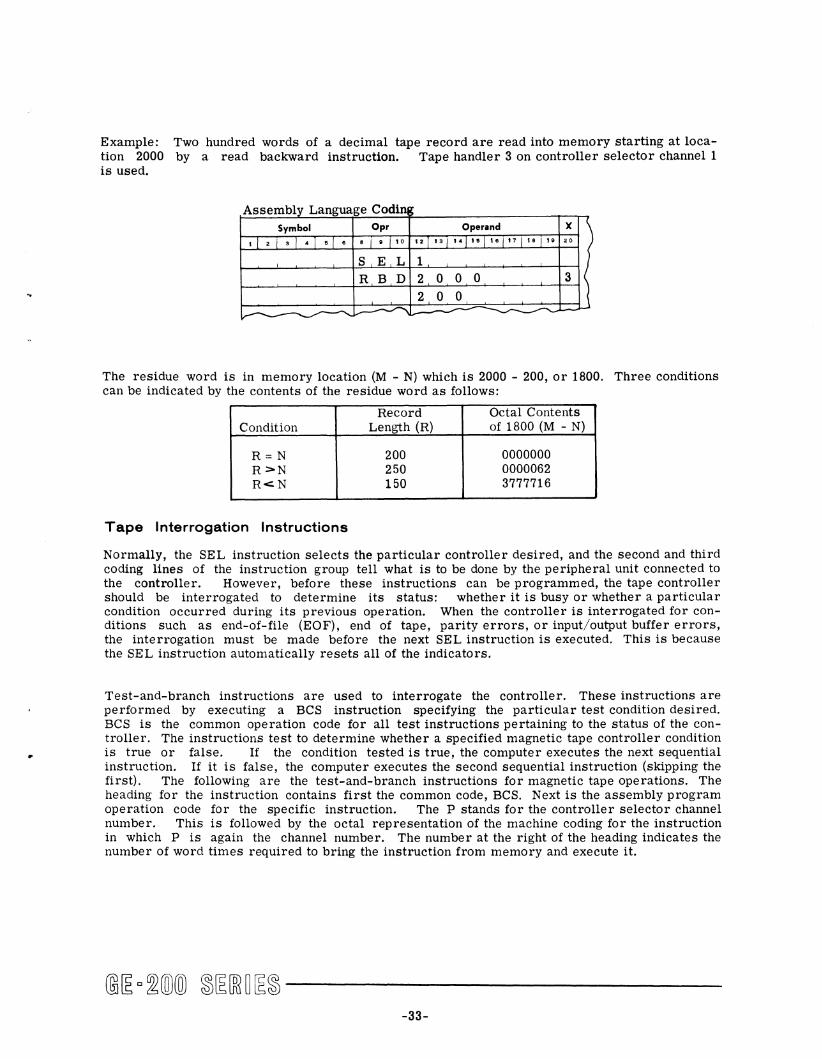
Example: Two hundred words of a decimal tape record are read into memory starting at location 2000. Tape handler 3 on tape controller 1 is used.
Assemblv Lamruae:e CodiIllI: Symbol Opr Operand X
.j2j.j_j_j. • I • I 10 .21 13 1 .. j IOj '.\17 1 18 i .. 20
I S E L 1
R T D 2 0 0 0 3
2 0 0
--The residue word is in memory location (M + N) which equals 2000 + 0200, or 2200. Three conditions can exist as shown by the chart below.
Record Octal Contents Condition Length (R) of 2200 (M + N)
R=N 200 0000000 R~N 250 0000062 R~N 100 3777634
If the programmer neglects to allow for the residue word, he runs the risk of destroying the contents of a memory location vital to the successful operation of his program.
2. Reading Tape Backward (any mode)
The residue word is always placed in memory location M - N. The first word is read into location M, the second is read into M - 1, and so forth. In reading tape backward, residue words are as follows:
a . Record length is exactly N words--The residue word consists of all zeros.
Example:
M location 0500
N 50 words
Record length = 50 words
@~c~®® ~~[ffi~~~------------31-
Information is stored in locations 0451 - 0500
Residue word is in location 0450
Residue word consists of all zeros
b. Record length is less than N words--The residue word consists of the 2's complement of the difference between N and the record length (N - record length) and 1. in the sign position.
Example:
M location 0500
N = 50 words
Record length = 30 words
Information is stored in locations 0471 - 0500 (0451 - 0471 remains unchanged)
Residue word is in location 0450
Residue word consists of the 2' s complement of 20 (which is 50 - 30) and 1. in the sign position
c. Record length is greater than N words--Only N words are read. The residue word consists of the number of excess words (record - N) and 0 in the sign position. The controller remains busy until the entire record has passed the read heads and the inter-record gap is reached.
Example:
M = location 0500
N 50 words
Record length = 75 words
Information is sorted in locations 0451 - 0500
Residue word location is 0450
Residue word consists of 25 (which is 75 - 50) and Q. in the sign position
The controller is busy until 75 words have passed the read head
The residue word resulting from a tape read operation indicates to the programmer the actual number of words read into memory and provides a way of determining the actual record length.
-32-
to
•
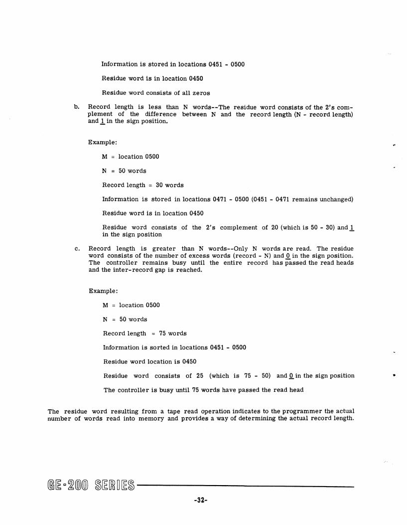
Example: Two hundred words of a decimal tape record are read into memory starting at location 2000 by a read backward instruction. Tape handler 3 on controller selector channel 1 is used.
Assembly Language Cdi 0 n Symbol Opr Operand X
, I 2 i • I • I • I • , I • I '0 12 113 1 141" I '"1" 1'8 i ,. 20
I S E L 1 R B D 2 0 0 0 3 (
2 0 0 J --- -----~~ --- ..............
The residue word is in memory location (M - N) which is 2000 - 200, or 1800. Three conditions can be indicated by the contents of the residue word as follows:
Record Octal Contents Condition Length (R) of 1800 (M - N)
R=N 200 0000000 R>N 250 0000062 R<N 150 3777716
Tape Interrogation Instructions
Normally, the SEL instruction selects the particular controller desired, and the second and third coding lines of the instruction group tell what is to be done by the peripheral unit connected to the controller. However, before these instructions can be programmed, the tape controller should be interrogated to determine its status: whether it is busy or whether a particular condition occurred during its previous operation. When the controller is interrogated for conditions such as end-of-file (EOF), end of tape, parity errors, or input/output buffer errors, the interrogation must be made before the next SEL instruction is executed. This is because the SEL instruction automatically resets all of the indicators.
Test-and-branch instructions are used to interrogate the controller. These instructions are performed by executing a BCS instruction specifying the particular test condition desired. BCS is the common operation code for all test instructions pertaining to the status of the controller. The instructions test to determine whether a specified magnetic tape controller condition is true or false. If the condition tested is true, the computer executes the next sequential instruction. If it is false, the computer executes the second sequential instruction (skipping the first). The following are the test-and-branch instructions for magnetic tape operations. The heading for the instruction contains first the common code, BCS. Next is the assembly program operation code for the specific instruction. The P stands for the controller selector channel number. This is followed by the octal representation of the machine coding for the instruction in which P is again the channel number. The number at the right of the heading indicates the number of word times required to bring the instruction from memory and execute it.
-33-

BRANCH ON TAPE CONTROLLER READY
BCS BTR P 2514P20
The tape controller is tested for the ready status.
BRANCH ON TAPE CONTROLLER NOT READY
BCS BTN P 2516P20
The tape controller P is tested for the not-ready status.
BRANCH ON END OF FILE
BCS BEF P 2514P21
The tape controller P is tested for end-of-file condition detected. (If true, the previous read command detected the end-of-file character 0001111).
BRANCH ON NO END OF FILE
BCS BNF P 2516P21
The tape controller P is tested for end-of-file condition not detected. (If true, the previous read command did .!!Q.t detect the end-of-file character 0001111.)
BRANCH ON END OF TAPE
BCS BET P 2514P22
The tape controller P is tested for end-of-tape condition detected. (If true, the direction of tape motion of the last instruction indicates which end of tape was detected. For example, if the previous instruction was a read backward, it was not executed and the tape handler is positioned on the load point marker. A second read backward instruction produces an error halt.)
BRANCH ON NO END OF TAPE
BCS BNT P 2516P22
The tape controller P is tested for end-of-tape condition not detected. (If true, the last instruction was executed and neither end of the tape was detected.)
-34-
•

•
BRANCH ON TAPE PARITY ERROR
BCS BPE P 2514P24
The tape controller P is tested for parity error detected. (If true, either a lateral or longitudinal parity error was detected during the execution of the previous instruction, or an unsuccessful erase was attempted.)
BRANCH ON TAPE PARITY CORRECT
BCS BPC P 2516P24
The tape controller P is tested for .!!Q. parity error detected. (If true, no parity error was detected during the execution of the previous instruction or an attempted erase was successful.)
BRANCH ON INPUT/OUTPUT BUFFER ERROR
BCS BlO P 2514P25
The tape controller P is tested for detection of an input/output buffer error. (If true, either a memory exhaust, overflow, or a parity error on data transfer from the controller selector was detected.)
BRANCH ON INPUT/OUTPUT BUFFER CORRECT
BCS BIC P 2516P25
The tape controller P is tested for an input/output buffer error not detected. (If true, no memory exhaust, overflow, or parity error on data transfer from the controller selector was detected.)
BRANCH ON MOD 3 OR 4 ERROR
BCS BME P 2514P26
The tape controller P is tested for occurrence of a modulo 3 or 4 error. (If true, a partial word was accumulated at the time the inter-record gap was detected during a Read instruction, indicating that reading was in the wrong mode.)
-35-
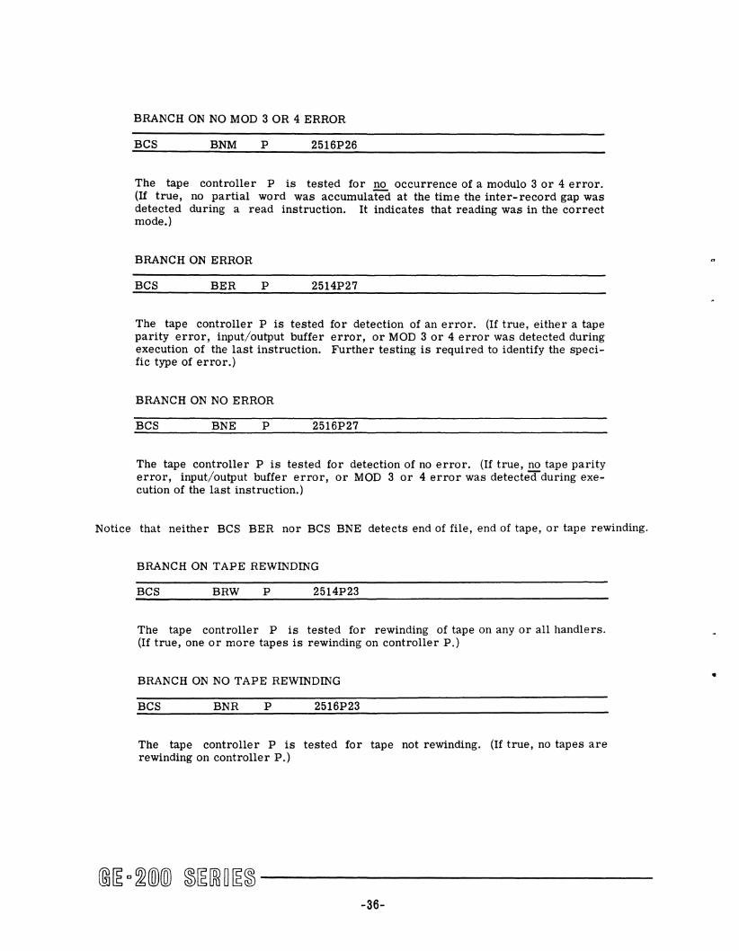
BRANCH ON NO MOD 3 OR 4 ERROR
BCS BNM P 2516P26
The tape controller P is tested for no occurrence of a modulo 3 or 4 error. (If true, no partial word was accumulated at the time the inter-record gap was detected during a read instruction. It indicates that reading was in the correct mode.)
BRANCH ON ERROR
BCS BER P 2514P27
The tape controller P is tested for detection of an error. (If true, either a tape parity error, input/output buffer error, or MOD 3 or 4 error was detected during execution of the last instruction. Further testing is required to identify the specific type of error.)
BRANCH ON NO ERROR
BCS BNE P 2516P27
The tape controller P is tested for detection of no error. (If true, no tape parity error, input/output buffer error, or MOD 3 or 4 error was detectedduring execution of the last instruction.)
Notice that neither BCS BER nor BCS BNE detects end of file, end of tape, or tape rewinding.
BRANCH ON TAPE REWINDING
BCS BRW P 2514P23
The tape controller P is tested for rewinding of tape on any or all handlers. (If true, one or more tapes is rewinding on controller P.)
BRANCH ON NO TAPE REWINDING
BCS BNR P 2516P23
The tape controller P is tested for tape not rewinding. (If true, no tapes are rewinding on controller P.)
-36-
•

•
The programmer must be aware that a rewind instruction for any tape handler on a controller puts that controller in the not-ready status for 250 microseconds, after which the controller returns to the ready status even though the tape handler is still rewinding. A read or write instruction can then be given to any tape unit that is not rewinding. The controller indicates when one or more tape units are rewinding at any time during the entire rewind operation. Addressing a rewinding tape unit to read or write causes an alert halt condition.
Thus, a rewind interrogation of a tape controller will indicate that a tape is rewinding without specifying which particular tape handler.
The assembly language coding for test-and-branch instructions places the controller selector channel number in column 20 of the coding sheet as is illustrated in the following example which checks for controller 2 being ready.
Example: Test tape controller on channel 2 for ready status.
A bl L ssem ly anguage Codi ng Symbol Opr Operand X )
,1·/·/·/"/" • 1 • 1 ,0 12 1" J .. J '"/ ,"\" \ .. i ,. 20
B C S B T N 2 ( I
] B R U * - 1
S E L 2
The BeS command in the example interrogates the controller on channel 2. If the controller is not ready, the central processor executes the next sequential instruction which is a branch back to the BeS command. Thus, a delay is effected until the controller becomes ready at which time the SEL command is executed and a tape operation can be performed.
When a magnetic tape controller is tested and found to be ready (not busy), any tape handler connected to it can be addressed by a read, write, read backwards, or rewind instruction, unless the tape handler already is rewinding. Tape handlers that are rewinding should not be addressed until the completion of the rewind operation.
A read, write, or read backward instruction puts the controller in the not-ready (busy) status until the completion of the operation. A rewind instruction puts the controller in a not-ready status for 250 microseconds, after which the controller returns to the ready status.
-37-

Example: Test tape controller on channel 1 for any error condition and branch to an error subroutine to determine the type of error, if any exists from the previous tape operation.
Assembly Language Coding
Symbol Opr Operand X
,1 21.1.1_1_ 8 I • I '0 '21 IS j ,. j Ie I,oj" I 18 I'. 20
B C S B E R 1
B R U E R R 0 R )
TECHNIQUES OF PROGRAMMING MAGNETIC TAPE
General Considerations
In processing information from magnetic tape, it is necessary that each tape be identified. Exterior labels on the tape container are required as well as interior labels on the tape itself. The interior labels are tested by the program. They must be placed in the first record of the tape, and must contain the date, identification, and reel number.
Before processing data from magnetic tape, it is good programming practice to rewind the tapes that are to be used. This makes sure that tape is at the load point when processing begins. The programmer also should program a tape rewind upon completion of processing and provide appropriate messages to the operator specifying what is to be done with the rewound tape. It is necessary to test the magnetic tape controller or controllers for ready status before attempting any tape operation.
Example 1. Flow Chart 1
HOUSEKEE PING:
Rewind MSTR Tape, Controller Channell, Handler 2.
Rewind TRANS Tape, Controller Channel 2, Handler 1.
-38-
•

A bi ssem ly Langu lite C oding Symbol Opr Operand X REMARKS
'I-L-]-]"- • I • 1'0 12 1"1 14 1'"1"1"1'81'" 20 31 75
S TAR T B C S B T N 1 CHECK FOR CONTROLLER BUSY B R U * - 1 DE LA Y FOR CONTROLLER BUSY S E L 1 SELECT CONTROLLER 1 ) RW D 2 REWIND TAPE HANDLER 2 B C S B T N 2 CHECK CONTROLLER 2 READY )
B R U * - 1 DELAY FOR CONTROLLER READY ( S E L 2 SELECT CONTROLLER 2 \ RW D 1 REWIND TAPE HANDLER 1
~-
After performing a tape operation on a controller and before using the controller for another operation, tests must be made to determine if the operation was successful or if any condition such as end of file, end of tape, etc., occurred. It is essential that these tests be made before another SEL command is executed since the SEL instruction clears the controller.
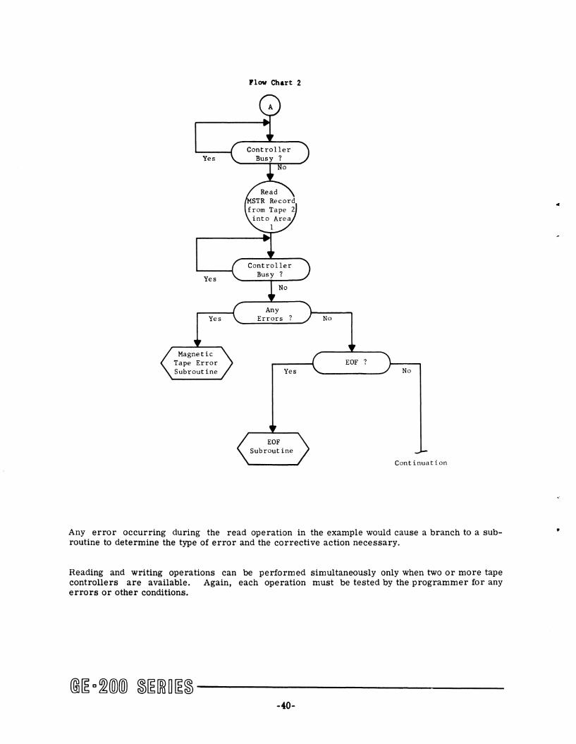
Example 2. Assume that tape handlers 2 and 3 of controller on channell are being used, as is indicated in the assembly language coding. The flow chart for this example is on the next page.
Assembly Language C d o ing Symbol Opr Operand X REMARKS Sequence
I L ' I 'J .~ I • J • • I ' I" 12.1 13~ I" jIll Jill i 17 liB j,lI " 31 75 78 77 78 " " A , B C S B T .N 1 CHECK FOR CONTROLLER BUSY 2 0 0
B R U * - 1 DELAY FOR CONTROLLER BUSY 2 1 ,0
S E L 1 SELECT CONTROLLER #1 2 2 0
R T D A R E A 1 2 READ MSTR RECORD 2 3 0
2 5 0 NO. WORDS IN RECORD 2 4 0
B C S B T N 1 CHECK FOR READ COMPLETED 2 5 0
B R U * - 1 DELAY FOR READ COMPLETED 2 6 0
B C S B E R 1 CHECK FOR READ ERROR 2 7 0
B R U E R R o R GO TO ERROR SUBROUTINE 2 8 0
B C S B E F 1 CHECK FOR END-OF-FILE 2 9 0
B R U E o F GO TO END-OF-FILE SUBROUTINE 3 0 0
- ---
@~ o~(O)(OJ ~~[ffi~~~ -------------39-
Flow Chart 2
Controller Yes Busy?
Yes
Yes
No
Any Errors
Yes
No
EOF No
Continuation
Any error occurring during the read operation in the example would cause a branch to a subroutine to determine the type of error and the corrective action necessary.
Reading and writing operations can be performed simultaneously only when two or more tape controllers are available. Again, each operation must be tested by the programmer for any errors or other conditions.
@[E C~(Q)(Q) ~[E[ffi~[E~ ------------40-
c
•
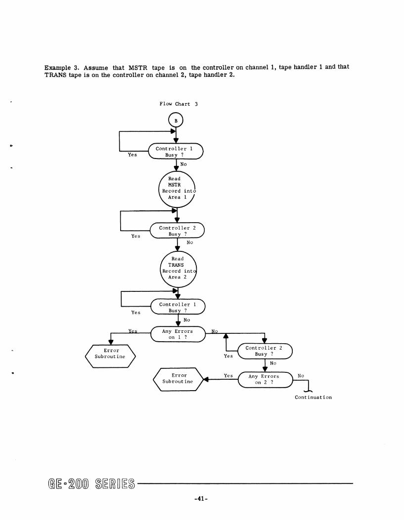
Example 3. Assume that MSTR tape is on the controller on channell, tape handler 1 and that TRANS tape is on the controller on channel 2, tape handler 2.
Flow Chart 3
Any Errors on 1 ?
Error Subroutine
-41-
Any Errors on 2 ?
2
Continuation

A bi L ssem lV angua.ge Coding Symbol Opr Operand X REMARKS Sequence
11' L '1' L -I 0 , I ' I" " 13 '4 Hi 18 " 18 111 " 31 7S 7e 77 71 711 80
B B C S B T N 1 CHECK CONTROLLER #1 BUSY 3 0 0 B R U * - 1 3 1 0 S E L 1 SELECT CONTROLLER #1 3 2 0 R T D A R E A # 1 1 READ MSTR RECORD 3 3 0
2 0 O. NO. WORDS 3 4 0 B C S B T N 2 CHECK CONTROLLER #2 BUSY 3 5 0 B R U * - 1 DELAY FOR CONTROLLER BUSY 3 6 (:)
S E L 2 SELECT CONTROLLER #2 3 7 0
R T D A R E A # 2 2 READ TRANS RECORD 3 8 0 2 0 0 NO. WORDS 3 9 0
B C S B T N 1 CHECK CONTROLLER #1 BUSY 4 0 0
B R U * - 1 DELAY FOR CONTROLLER BUSY 4 1 0 B C S B E R 1 CHECK FOR ANY ERROR 4 2 0 B R U E R R 0 R GO TO ERROR SUBROUTINE 4 3 0 B C S B T N 2 CHECK CONTROLLER #2 BUSY 4 4 0
B R U * - 1 , DELAY FOR CONTROLLER BUSY 4 5 0
B C S B E R. 2 CHECK FOR ANY ERROR 4 6 0 B RUE R R 0 R GO TO ERROR SUBROUTINE 4 7 0
PROCEES
Example 4. At the conclusion of processing an old master file on controller on channell, handler 1 and creating a new master file on controller on channel 2, handler 2, write an endof-file record on the new master and rewind both tapes.
A bi L ssem ly angu a.ge Cd' o m.g Symbol Opr Operand X REMARKS Sequence
II ' 1 ' 1 • L oJ 0 'j , LIO " 13 14 Hi Ie " 18 HI " 31 75 7e 17 78 711 80
B C S B T N 1 CHECK CONTROLLER #1 BUSY 5 2 0
B R U * - 1 DELAY FOR CONTROLLER BUSY 5 3 ,0
S E L 1 SELECT CONTROLLER #1 5 4 0
RW D 1 REWIND TU #1 5 5 0
B C S B T N 2 CHECK CONTROLLER #2 BUSY 5 6 0
B R U * - 1 DELAY FOR CONTROLLER BUSY 5 7 0
S E L 2 SELECT CONTROLLER #2 5 8 0
WE F 2 WRITE EOF ON TU #2 5 9 0
B C S B T N 2 CHECK FOR EOF COMPLETION 6 0 0
B R U * - 1 DELAY FOR COMPLETION 6 1 0
S E L 2 SELECT CONTROLLER #2 6 2 0
R W D 2 REWIND TU #2 6 3 0
,
~
@[E o~@@ ~[E[ffiO[E~ ------------42-
..
Assembly Language Coding Symbol Op' Ope,"nd X REMARKS Sequence
• . . . . . .J • I" u. U 14 •• Ie 17 I. Ie 20 31 75 'Ie 77 78 7. 10
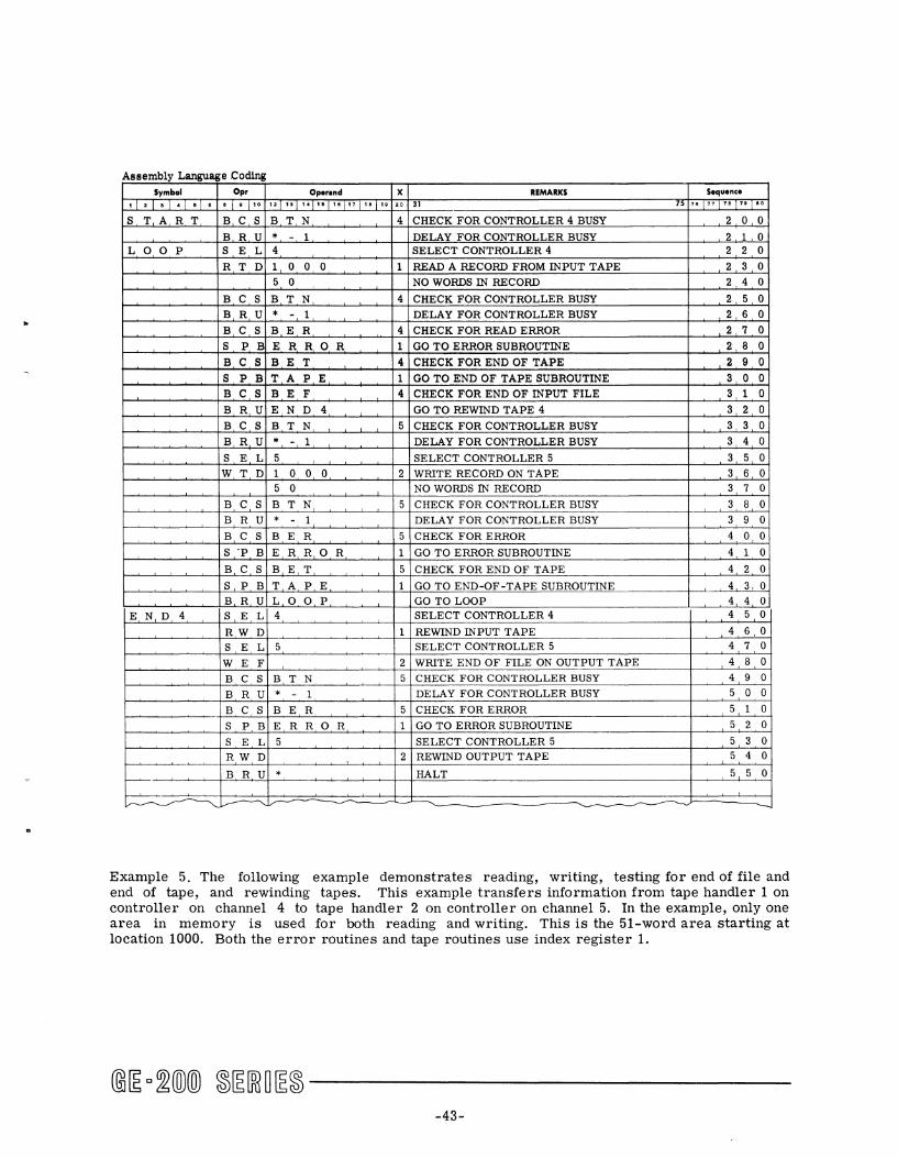
S T A R T B C S B T N 4 CHECK FOR CONTROLLER 4 BUSY 2 0 0
B R U * - 1 DELAY FOR CONTROLLER BUSY 2 1 0 L o 0 P S E L 4 SELECT CONTROLLER 4 2 2 0
R T D 1 0 0 0 1 READ A RECORD FROM INPUT TAPE 2 3 0
5 0 NO WORDS IN RECORD 2 4 0
B C S B T N 4 CHECK FOR CONTROLLER BUSY 2 5 0
B R U * - 1 DELAY FOR CONTROLLER BUSY 2 6 0
B C S B E R 4 CHECK FOR READ ERROR 2 7 0
S P B ERR 0 R 1 GO TO ERROR SUBROUTINE 2 8 0
B C S B E T 4 CHECK FOR END OF TAPE 2 9 0
S P B T A P E 1 GO TO END OF TAPE SUBROUTINE 3 0 0
B C S B E F 4 CHECK FOR END OF INPUT FILE 3 1 0
B R U E N D 4 GO TO REWIND TAPE 4 3 2 0
B C S B T N 5 CHECK FOR CONTROLLER BUSY 3 3 0
B R U * - 1 DELAY FOR CONTROLLER BUSY 3 4 0
S E L 5 SELECT CONTROLLER 5 3 5 0
W T D 1 0 0 0 2 WRITE RECORD ON TAPE 3 6 0 5 0 NO WORDS rN RECORD 3 7 0
B C S B T N 5 CHECK FOR CONTROLLER BUSY 3 8 0
B R U * - 1 DELAY FOR CONTROLLER BUSY 3 9 0
B C S B E R 5 CHECK FOR ERROR 4 0 0 S .p B E R R 0 R 1 GO TO ERROR SUBROUTINE 4 1 0
B C S B E T 5 CHECK FOR END OF TAPE 4 2 0
S P B T A P E 1 GO TO END-OF-TAPE SUBROUTINE 4 3 0 B R U L 0 0 P GO TO LOOP 4 4 0
END 4 S E L 4 SELECT CONTROLLER 4 4 5 0
RW D 1 REWIND INPUT TAPE 4 6,0
S E L 5 SELECT CONTROLLER 5 4 7 0
W E F , 2 WRITE END OF FILE ON OUTPUT TAPE 4 8 0
B C S B T N 5 CHECK FOR CONTROLLER BUSY 4 9 0
B R U * - 1 DELAY FOR CONTROLLER BUSY 5 0 0
B C S B E R. 5 CHECK FOR ERROR 5 1 0
S P B E R R OR 1 GO TO ERROR SUBROUTINE 5 2 0
S E L 5 SELECT CONTROLLER 5 5 3 0
RW D 2 REWIND OUTPUT TAPE 5 4 0
B R U * HALT 5 5 0
~~ ~~ ---
Example 5. The following example demonstrates reading, writing, testing for end of file and end of tape, and rewinding tapes. This example transfers information from tape handler 1 on controller on channel 4 to tape handler 2 on controller on channel 5. In the example, only one area in memory is used for both reading and writing. This is the 51-word area starting at location 1000. Both the error routines and tape routines use index register 1.
@~ c~ill)(ID ~~[ffiO~~ ------------43-
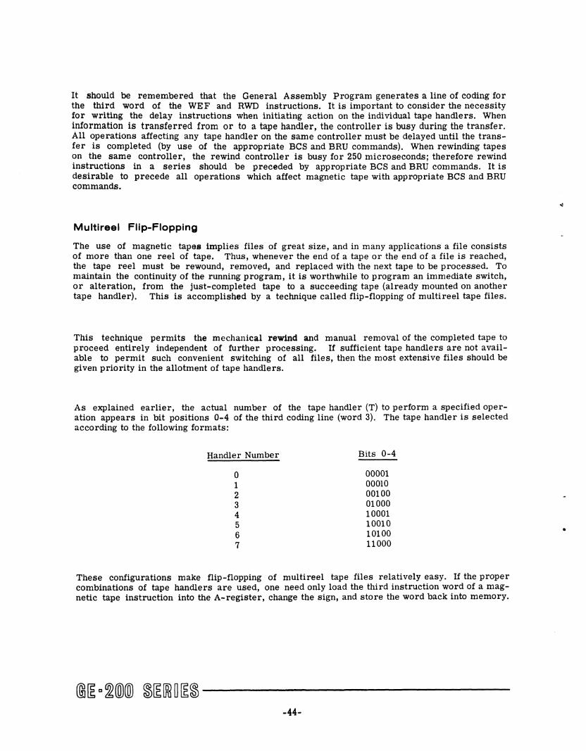
It should be remembered that the General Assembly Program generates a line of coding for the third word of the WEF and RWD instructions. It is important to consider the necessity for writing the delay instructions when initiating action on the individual tape handlers. When information is transferred from or to a tape handler, the controller is busy during the transfer. All operations affecting any tape handler on the same controller must be delayed until the transfer is completed (by use of the appropriate BCS and BRU commands). When rewinding tapes on the same controller, the rewind controller is busy for 250 microseconds; therefore rewind instructions in a series should be preceded by appropriate BCS and BRU commands. It is desirable to precede all operations which affect magnetic tape with appropriate BCS and BRU commands.
Multireel Flip-Flopping
The use of magnetic tapes implies files of great size, and in many applications a file consists of more than one reel of tape. Thus, whenever the end of a tape or the end of a file is reached, the tape reel must be rewound, removed, and replaced with the next tape to be processed. To maintain the continuity of the running program, it is worthwhile to program an immediate switch, or alteration, from the just-completed tape to a succeeding tape (already mounted on another tape handler). This is accomplished by a technique called flip-flopping of multi reel tape files.
This technique permits the mechanical rewind and manual removal of the completed tape to proceed entirely independent of further processing. If sufficient tape handlers are not available to permit such convenient switching of all files, then the most extensive files should be given priority in the allotment of tape handlers.
As explained earlier, the actual number of the tape handler (T) to perform a specified operation appears in bit positions 0-4 of the third coding line (word 3). The tape handler is selected according to the following formats:
Handler Number Bits 0-4
0 00001 1 00010 2 00100 3 01000 4 10001 5 10010 6 10100 7 11000
These configurations make flip-flopping of multi reel tape files relatively easy. If the proper combinations of tape handlers are used, one need only load the third instruction word of a magnetic tape instruction into the A-register, change the Sign, and store the word back into memory.
-44-
•
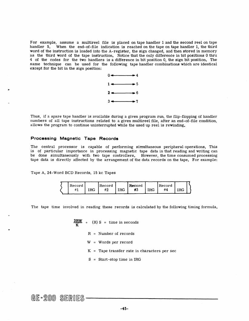
•
For example, assume a multireel file is placed on tape handler 1 and the second reel on tape handler 5. When the end-of-file indication is reached on the tape on tape handler 1, the third word of the instruction is loaded into the A-register, the sign changed, and then stored in memory as the third word of the tape instruction. Notice that the only difference in bit positions 0 thru 4 of the codes for the two handlers is a difference in bit position 0, the sign bit position. The same technique can be used for the following tape handler combinations which are identical except for the bit in the sign position:
1 • -5
-7
Thus, if a spare tape handler is available during a given program run, the flip-flopping of handler numbers of all tape instructions related to a given multireel file, after an end-of-file condition, allows the program to continue uninterrupted while the used up reel is rewinding.
Processing Magnetic Tape Records
The central processor is capable of performing simultaneous peripheral operations. This is of particular importance in processing magnetic tape data in that reading and writing can be done simultaneously with two tape controllers. However, the time consumed processing tape data is directly affected by the arrangement of the data records on the tape. For example:
Tape A. 24-Word BCD Records, 15 kc Tapes
~ Record Record Record Record J #1 IRG #2 IRG #3 IRG #4 IRG
The tape time involved in reading these records is calculated by the following timing formula.
3RW + (R) S = time in seconds K
R Number of records
W Words per record
K Tape transfer rate in characters per sec
S = Start -stop time in IRG
-45-
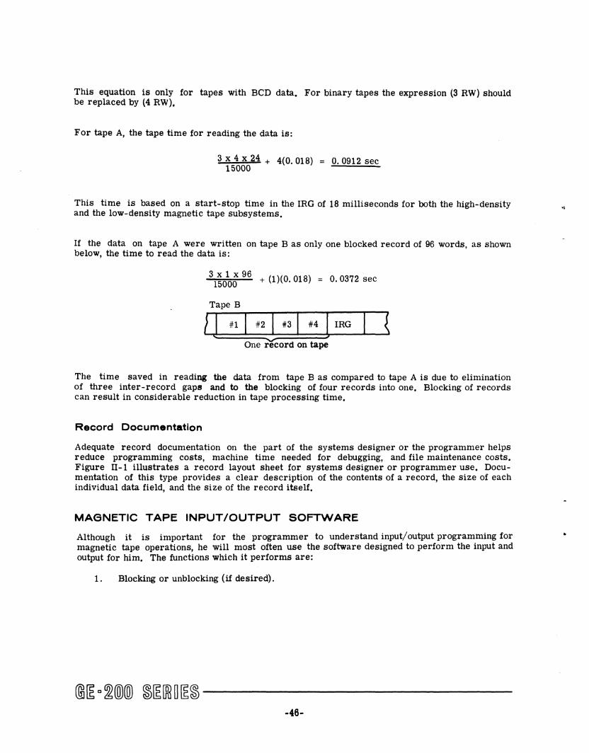
This equation is only for tapes with BCD data. For binary tapes the expression (3 RW) should be replaced by (4 RW).
For tape A, the tape time for reading the data is:
3 x 4 x 24 + 4(0.018) 15000
0.0912 sec
This time is based on a start-stop time in the IRG of 18 milliseconds for both the high-density and the low-density magnetic tape subsystems.
If the data on tape A were written on tape B as only one blocked record of 96 words, as shown below, the time to read the data is;
3 x 1 x 96 + (1)(0.018) 15000
Tape B
0.0372 sec
} J #1 I #2} #31 #4 l IRG I { One record on tape
The time saved in reading the data from tape B as compared to tape A is due to elimination of three inter-record gaps and to the blocking of four records into one. Blocking of records can result in considerable reduction in tape processing time.
Record Documentation
Adequate record documentation on the part of the systems designer or the programmer helps reduce programming costs, machine time needed for debugging, and file maintenance costs. Figure 11-1 illustrates a record layout sheet for systems designer or programmer use. Documentation of this type provides a clear description of the contents of a record, the size of each individual data field, and the size of the record itself.
MAGNETIC TAPE INPUT/OUTPUT SOFTWARE
Although it is important for the programmer to understand input! output programming for magnetic tape operations, he will most often use the software designed to perform the input and output for him. The functions which it performs are:
1. Blocking or unblocking (if desired).
@J~ a~(Q)(ID ~~[ffi~~~ ------------46-
..

RUN, *2 Inventory Control GENERAL. ELECTRIC
DATE, 1/30/63
c,;:::;:~~::~:"' PROGRAMMER, GE Coder FILE, mv MSTR
RECORD TYPE BCD , , , GE 225 MAGNETIC TAPE RECORD LAYOUT SHEET PAGE 1 OF 20 4 Stock * "I~ Item Description • I 1 3 5 6 7
I I I I I I I I I I I I I I I I I I I I I I I •
, , ID 10 -11, Balance on Hand_l~
11 , ~tit~ on an "b-BaCkOrder
15
I I I I I I I I L I I I I I I I I I I I I I I ~uantity 'b Reorder pOint_l_ }!;COnOmlC JQnl~ f Blank ..
18 ~ 19 OrdeJj Quantity- ~Cost -.~ 13
I I I I I I I I I I I I C I I I I I I I I I I I
24 25 26 27 28 19 ., 31
I I I I I I I I I I I I I I I I I I I I I I I
31 3l 34 35 36 37 38 39
I I I I I I J J I I I I I I I I I I I I I I I
'" 41 41 43 44 45 46 47
I I I I I I 1 1 L I I I I I I I I I I I I' I I 48 49 50 51 52 53 54 55
I I I I I I I I I I I I I I I I I I I I I I I
" 57 58 " 60 61 62 63
i I I I I I I I I I I I I I I I I I I I I I I
64 65 66 67 ~ 69 70 71
I I I I I I I I I I I I ! I I I I I I I I I I
71 73 74 75 76 77 78 19
I I I I I I I I I I I I I I I I I I I I I I I
!O 8I 82 83 .. 85 86 87
I I I I I 1 1 L 1 I 1 L I 1 L I I I I I I I I
Figure 18. Sample Magnetic Tape Record Layout Sheet
2. Reading and writing in 20-bit binary, BCD, Qr 18-bit binary format.
3. Buffering (if desired).
4. Detecting read/write errors and attempted reread/rewrite errors.
5. Rewinding.
6. Swapping magnetic tape.
7. Counting blocks and logical record.
8. Checking and writing labels.
@j~ c~(Q)(Q) ~~[ffiO~~ ------------47-
9. End-of-file functions.
10. End-of-tape functions.
11. Rerun functions.
12. Producing typewriter messages concerning magnetic tape files.
13. Executing user's coding sections at beginning and ending of magnetic tapes, end of file, and rerun point.
For a more complete description of what the system does and of how it is used, refer to the publication CPB-265, GE-225 Symbolic Tape Input/Output System, SIOS.
@~a~@)(ID ~~[ffi~~~ -----------
-48-
3. OPERATING PROCEDURES
MAGNETIC TAPE CONTROLS AND INDICATORS
Before explaining actual operations, individual switches and indicators will be reviewed. These have already been described in Chapter lof this manual.
Tape Handlers
The control and indicator panel for tape handler models 680 and 690 is shown on Figure 19. The panels for both models appear to be identical. There is, however, one difference. On model 680, the HI DEN/La DEN switch is locked at the La DEN pOSition of 200 bits per inch. Since only one density of tape can be used with model 680, there is no need to use a density switch. Figure 20 summarizes the descriptions of tape handler switches and indicators, All switches except the rotary selector switch are of the pushbutton type,
Tape Controllers
Magnetic tape controllers for subsystem models 680 and 690 have control and indicator panels like the one shown at the top of Figure 19. Functions of these switches and indicators and their use are the same for both models. All switches are of the pushbutton type. They are summarized in Figure 20.
-49-
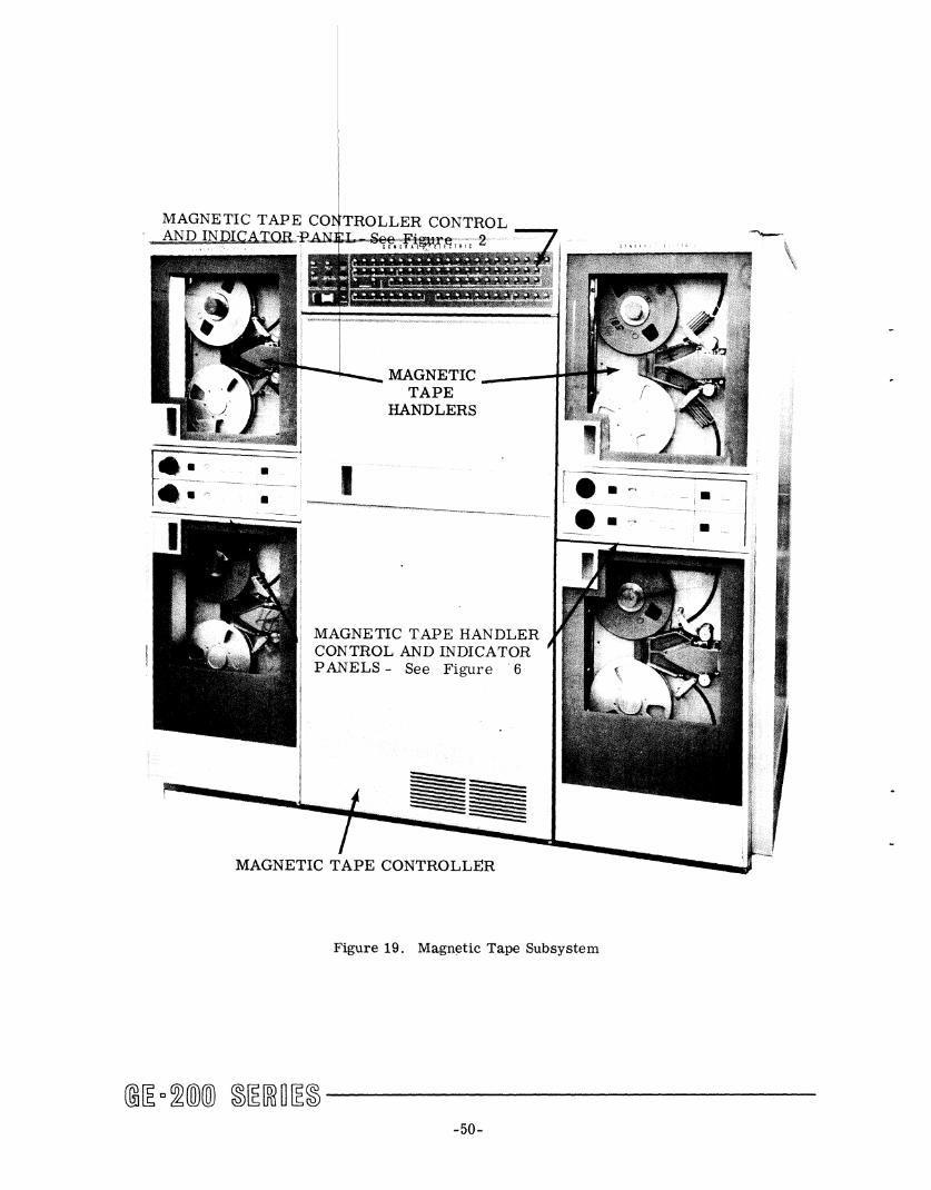
• • I
MAGNETIC TAPE HANDLER CONTROL AND INDICATOR PANELS - See Figure . 6
MAGNETIC TAPE CONTROLLER
Figure 19. Magnc;!tic Tape Subsystem
@~ c~(Q)(ID ~~[ffiO~~ -------------50-

Location
Magnetic tape handler control and indicator panel, (See Figure 6).
Control or Indicator
Rotary selector switch and indicator.
POWER ON switch and .. indicator (red).
REMOTE/LOCAL switch and indicator (REMOTE is blue, LOCAL is white).
REWIND switch and indicator (white) •
REVERSE switch and indicator (white).
FORWARD switch and indicator (white).
STOP switch.
ADDR/WRITE INH indieator (white) •
Function
Establishes and indicates address on the controller of the magnetic tape handler.
Turns on power to the magnetic tape handler when depressed once; turns power Glff ,w.helil depreued again. Glows red to indicate wheft power is on.
Determines and indicates by illumination whether operation is to be REMOTE (online) by the central processor or LOCAL (off-line at the handler's control panel)
Rewinds magnetic tape at double speed (150 inches/second) under manual control when REMOTE/LOCAL switch is in LOCAL position. Stops on the leader marker. Glows white during rewind.
Moves tape in the rewind direction at normal speed (75 inches/second) under manual control when REMOTE/LOCAL switch is in LOCAL position. Stops on the leader ma»ker. Glows white during reverse mevement.
Moves tape in the forward direction at normal speed under manual control when REMOTE/LOCAL switch is in LOCAL position. Glows white during forward motion.
Halts tape movement under manual control when REMOTE/LOCAL switch is in LOCAL position.
ADDR half of indicator glows white when the tape handler is being addressed for either a read or write operation.
WRITE INH half of indicator glows white when tape supply reel does not have a write-permit ring installed (only reading is possible).
Figure 20. Summary of Controls and Indicators
@~ D~(Q)(ID ~~[ffi~[E~ ------------51-
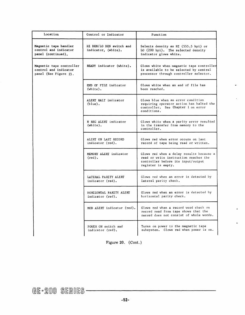
Location Control or Indicator Function
Magnetic tape handler HI DEN/LO DEN switch and Selects density as HI (555.5 bpi) or control and indicator indicator, (white) • 10 (200 bpi). The selected density panel (continued) • indicator glows white.
Magnetic tape controller READY indicator (white) • Glows white when magnetic tape controlle control and indicator is available to be selected by central panel (See Figure 2) . processor through controller selector.
END OF FILE indicator Glows white when an end of file has (white) • been reached.
ALERT HALT indicator Glows blue when an error condition (blue) • requiring operator action has halted the
controller. See Chapter I on error cond it ions.
N REG ALERT indicator Glows white when a parity error resulted (white). in the transfer from memory to the
controller.
ALERT ON LAST RECORD Glows red when error occurs on last indicator (red). record of tape being read or written.
MEMORY ALERT indicator Glows red when a delay results because a (red). read or write instruction reaches the
controller before its input/output register is empty.
LATERAL PARITY ALERT Glows red when an error is detected by indicator (red). lateral parity check.
HORIZONTAL PARITY ALERT Glows red when an error is detected by indicator (red). horizontal parity check.
MOD ALERT indicator (red). Glows red when a record word check on record read from tape shows that the record does not consist of whole words.
POWER ON switch and Turns on power to the magnetic tape indicator (red). subsystem. Glows red when power is on.
Figure 20. ( Cont. )
@[E 0 ~(D)(ill ~[E[ffi~[E~ ------------52-

Location Control or Indicator Function
Magnetic tape controller POWER OFF switch. Turns power off to magnetic tape sub-control and indicator system. panel (continued).
CLEAR switch. Clears circuitry of error indications after alert halt condition has occurred.
N REGISTER display Glow white to display contents of N indicators (white) • register which serves as input/output
buffer between magnetic tape subsystem and central processor.
INST REGISTER display Glow white to display operation code indicators (white) • portion of current inst ruct ion.
ADDRESS REGISTER display Glow white to display address (location indicators (white) • in memory) portion of current instruc-
tion.
PRIORITY display Glow white to indicate phases of con-indicators (white) • troller access to central processor.
WORD COUNTER display Glow white to display quantity of words indicators (white) • to be written on or read from tape.
TAPE UNIT REGISTER display Glow white to indicate which magnetic indicators (white) • tape handler is currently engaged.
PROGRAM COUNTER display Glow white to indicate sequencing in indicators (white). the controller.
CHARACTER COUNTER display Glow white to indicate the character indicators (white). count as words are read from or written
on tape.
Figure 20. ( Cont. )
@~ c~(ID(ID ~~[ffi~~~ ------------
-53-

STARTING PROGRAM OPERATION
After the central processor is readied for operation, the following steps initiate magnetic tape operations:
1. Depress the POWER ON switch on the magnetic tape controller (it will glow red). 2. Depress the POWER ON switch on the tape handler to be used (it will glow red). 3. Mount tapes on the handlers (instructions for this follow). 4. By use of the console of the central processor, start tape operations as follows:
a. If the system has a card reader--use a call card to initiate tape reading. Almost any combination of the use of cards and magnetic tape is possible. For example, both the program and the data can be on tape; the program can be on cards and the data on tape or vice versa; or, the master file of data can be on tape and the program and transaction file of data can be on cards. See the Compatibles/200 Punched Card Subsystem Reference Manual CPB-302 for card reading instructions.
b. If the system is without a card reader--tape reading is initiated by a bootstrap program which is entered manually by means of console switches. When the bootstrap program is executed, it reads in the first tape record, which is a loader. The loader in turn reads in the program, any necessary data, and starts program execution. The example which follows demonstrates entering a bootstrap program to read binary tape. The bootstrap program consists of six instructions stored in memory locations (00144 - 00151) and tape is read into memory beginning at location zero. All switches refer~ed to in the example below are on the console of the central processor. Refer to the GE-225 or GE-235 Reference Manuals CPB-252A and CPB-374 for console switch descriptions.
Use tape controller on channel 1 and tape handler 2 and initiate reading the binary tape. Enter the bootstrap program as follows:
1. Set the INSTR/WORD switch to the INSTR position.
2. Set the AUTO/MANUAL switch to the MANUAL position.
3. Toggle the RESET A switch to clear the A-register.
4. Load an STA instruction into the A-register using the A-register input switches. This instruction is an octal 0300144, in which (00144)8 is the memory address where the information in the A-register is to be stored.
5. Depress the A ... I switch.
6. Toggle the RESET A switch.
7. Load a SEL instruction into the A-register using the A-register input switches. This instruction is an octal 2500P20 in which P is to be controller on channel 1.
-54-
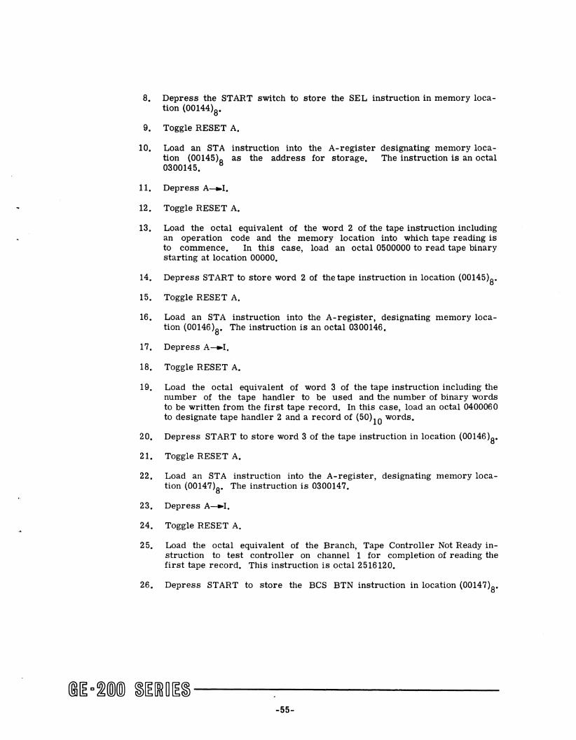
8. Depress the START switch to store the SEL instruction in memory location (00144)8.
9. Toggle RESET A.
10. Load an STA instruction into the A-register designating memory location (00145)8 as the address for storage. The instruction is an octal 0300145.
11. Depress A_I.
12. Toggle RESET A.
13. Load the octal equivalent of the word 2 of the tape instruction including an operation code and the memory location into which tape reading is to commence. In this case, load an octal 0500000 to read tape binary starting at location 00000.
14. Depress START to store word 2 of the tape instruction in location (00145)8.
15. Toggle RESET A.
16. Load an STA instruction into the A-register, designating memory location (00146)8. The instruction is an octal 0300146.
17. Depress A_I.
18. Toggle RESET A.
19. Load the octal equivalent of word 3 of the tape instruction including the number of the tape handler to be used and the number of binary words to be written from the first tape record. In this case, load an octal 0400060 to designate tape handler 2 and a record of (50)10 words.
20. Depress START to store word 3 of the tape instruction in location (00146)8.
21. Toggle RESET A.
22. Load an STA instruction into the A-register, designating memory location (00147)8. The instruction is 0300147.
23. Depress A_I.
24. Toggle RESET A.
25. Load the octal equivalent of the Branch, Tape Controller Not Ready instruction to test controller on channel 1 for completion of reading the first tape record. This instruction is octal 2516120.
26. Depress START to store the BCS BTN instruction in location (00147)8'
@~D~m)(ID ~~[ffi~~~ ------------55-

27. Toggle RESET A.
28. Load an STA instruction into the A-register, designating memory location (00150)8' The instruction is 0300150.
29. Depress A_I.
30. Toggle RESET A.
31. Load the octal equivalent of the BRU instruction to complete the branch test. This instruction is an octal 2600147, in which 00147 is the location of the BCS BTN instruction.
32. Depress START to store the BRU instruction in location (00150)8'
33. Toggle RESET A.
34. Load an STA instruction into the A-register, designating memory location (00151)8' The instruction is an octal 0300151.
35. Depress A-..I.
36. Toggle RESET A.
36. Toggle RESET A.
37. Load the octal equivalent of the BRU instruction to branch to the first location into which tape has just been read. This starts execution of the instructions of the loader. The BRU instruction is octal 2600000 with zero as the location of the branch.
38. Depress START to store the BRU instruction in location (00151)8'
~9. Toggle RESET A.
40. Load the octal equivalent of the BRU instruction to branch to the first instruction of the bootstrap program. This is the SEL instruction in location (00144)8' The BRU instruction is an octal 2600144.
41. Depress A-I.
42. Set the AUTO/MANUAL switch to the AUTO position.
43. Depress START.
MOUNTING TAPE
The steps in mounting tapes are as follows. Unless specified otherwise, controls and indicators referred to are on the tape handler control and indicator panel. See Figure 21.
1. Check to make sure the service engineer has connected the magnetic tape controller to the correct controller selector channel. The identification number on the channel
@~ Q~(Q)(ill ~~[ffi~~~ ------------56-

must correspond to the address specified by the program for this magnetic tape controller. This number is included in the operating instructions for the program.
2. Depress the POWER ON switch located on the magnetic tape controller control and indicator panel.
3. Depress the POWER ON switch on the magnetic tape handler control and indicator panel of each handler to be used.
4. Ready each magnetic tape handler to be used for reading or writing as follows:
a. Set the REMOTE/LOCAL switch to the LOCAL position.
b. Select a reel of tape.
(1) If the tape is to be used for writing, select a scratch reel of tape (one with no information to be saved) and install a write-permit ring in the groove on the back of the reel to permit writing.
(2) If the tape is to be used for reading, check the label to see that it is the correct tape and make sure that the write-permit ring is removed.
c. Place the tape reel (grooved side first) onto the upper reel mounting hub. The reel must be fully seated on the mount; hold the reel in place with one hand (be sure to press only on the reel hub) and tighten the knob by turning it clockwise. Never tighten the reel mount knob more than necessary to secure the reel; overtightening will result in damaging the threads of the knob screw.
d. Pull the dust cover open slowly. This causes the tape takeup arms to be pulled into the open pOSition. There must be an audible click as the mechanism goes into the cocked pOSition. If the click is not heard, close the dust cover and reopen it slowly to cause the click. This procedure also releases brakes holding the mount hubs and allows the reels to turn freely.
e. Thread the tape leader through the guides as shown in Figure 21. Wind the end of the tape leader around the hub of the takeup reel and manually turn the reel approximately six revolutions (clockwise) to secure the tape. The tape end must lie straight and flat on the lower reel. If the tape is folded, bunched, or protrudes from the reel, it could cause damage to the working portion of the tape.
f. Prior to closing the dust cover, pull it back slightly to release the thread switch. Do not let it slam; it could cause damage to the handler assembly.
g. If tape is not drawn into the vacuum pocket by the vacuum, tap the tape lightly over the vacuum pocket opening until the tape is drawn into the opening.
h. Depress the FORWARD switch.
(1) If the tape is threaded properly, the load point marker has not yet passed the senSing cells, and the tape will stop on or a little beyond the foil.
-57-

Figure 21. Threading Tape Through Magnetic Tape Handler
(2) If the tape happened ti' be threaded with the load point marker beyond the sensing cells, the tape '""ill keep right on gOing. In this case, the operator must stop the tape L.Y dep ',.:;smg STOP.
i. Depress the REwum ;::witch "rIC''', the tape to the load point marker.
j. Set the selector switch t" 118 rn;)T,bcr required bv the program.
k. Depress the CLE.\b c· JJitch (On thc magnetiC' tape controller control and indicator panel.
1. Set the REMOTE/LOCA:'" .' -". t.n the REMOTE position.
-58-
UNLOADING TAPE
After a program has been run, remove tapes as follows (included are the shutdown procedures for the magnetic tape subsystem, which apply only at the time of system shutdown at the end of the day):
1. Rewind any magnetic tapes not rewound by program control as follows:
a. Set the REMOTE/LOCAL switch to the LOCAL position.
b. If tape appears to be rewound to approximately the load point marker, depress REVERSE to make sure it is on the foil.
c. If a considerable amount of tape is on the takeup reel, depress REWIND to bring the tape more quickly to the leader foil.
d. Open the dust cover slightly so the vacuum decreases slowly; otherwise, tape can be sucked into the pockets and cause damage.
e. Rewind the upper reel by turning it by hand until all the tape is rewound. The hand winding prevents causing damage to both tape and equipment.
2. Remove the top reel of magnetic tape from each magnetic tape handler used in the program as follows:
a. Turn the knob in the center of the top reel mounting hub counterclockwise to release the reel.
b. Remove the reel.
(1) If the information on the reel is not to be saved, place it in a clean container and store it with "non-save" tapes.
(2) If the information on the reel 1&. to be saved, make doubly sure to remove the write-permit ring, and fasten an adhesive-backed label with the following or similar information (as specified locally) onto the reel:
Date
Particular tape handler used
Programmer or project name and the destination of tape (name of program or programmer that will use it).
Place the reel in a clean container and file it in an area specified for tapes to be saved.
3. If it is the end of the day's operation, or normal shutdown for some other reason, the following additional steps should be taken:
a. Release the spring tension on the dust covers to avoid damage to the covers' springs.
@[E o~mJ(ID ~[E[ffi~ [E~ -------------59-
b. Depress each lighted POWER ON switch on the magnetic tape handlers to turn off power to these units. Power to the handlers must be turned off before it is turned off to their controllers.
c. Depress the POWER OFF switch on each magnetic tape controller.
SPECIAL PROCEDURES
Using Operator Instruction Forms
Various types of forms are used at individual computer sites, and the operator needs to become familiar with these. The forms illustrated in this section are samples of types of forms used in connection with magnetic tape operations.
Operator Instruction Cards. Cards are used to provide a compact form of instructions to the operatOr, as illustrated in Figure 22. Here, all necessary information is written on a card the size of a tab card. It should be noted that on each of these cards there is a space for the operator to write his initials, the date, the running time of the program, as well as any special remarks about the operation of the run.
Operator Instruction Sheet. This form, illustrated in Figure 23, was developed for use in run bOoks, but is also found useful in giving instructions for nonproductive types of runs and during debugging stages of runs which would later have their own run books.
@~ a~ffi)(ID ~~[ffi~~~ ------------60-

JoeNO~ IIXT..ALZ.Z
Of"IERATOR COMMENTS:
Cll&COM Cl GAP 412 0 X GAP 0 WIZ 0 C:PM I~ L.P. 0 * PAftTS LOOPS.
SPECIAL INST I
I-I--
OU'IPUT
NORMAL. STOP IS 20~O DUMP CORE 'I. DUMP TAPES 14-
~·::N ;: ~;:~~ RUNNING TIME 2f? ~';,;1 OPERATOR I ~--=r""
Figure 22. Two Types of Operator Instruction Cards
GE 225 OPERATOR INSTRUCTION SHEET RUN ______________ __
SYSTEM
~ CK 64 PROGRAMMER C '.;;§; 'Ii' DATE
;~~ PLUG TAPE DATA DATE DISPOSITION NBR REEL IDENTIFICATION CREATED
OTHER PERIPHERAL DATA
UNITS USED IDENTIFICATION 0
1 '.?4 'J .. H. -h , ,;; 'L ~~, (CARD READER) C/,..?:: +i;. 2 3. ;-1.';. , :<!.
CARD PUNCH
3 IA) .k
4 1N •• 1( (HIGH SPEED J.. .. sU,,~ of
PRINTER 1111.. H. .12.L "7
5 MRAF
6 I---~ 1--.
7
SET SWITCHES
• FUNCTION
3 --:v.. . ,I "7
PRUN INSTRUCTION .. S_, ____________________________ ----.J
Figure 23. Sample Instruction Sheet for UperatOrs
-61-
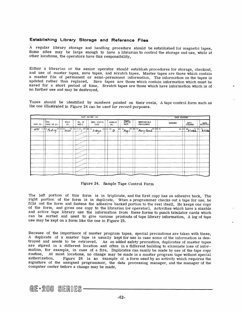
Establishing Library Storage and Reference Files
A regular library storage and handling procedure should be established for magnetic tapes. Some sites may be large enough to have a librarian to control the storage and use, while at other locations, the operators have this responsibility.
Either a librarian or the senior operator should establish procedures for storage, checkout, and use of master tapes, save tapes, and scratch tapes. Master tapes are those which contain a master file of permanent or semi-permanent information. The information on the tapes is updated rather than replaced. Save tapes are those which contain information which must be saved for a short period of time. Scratch tapes are those which have information which is of no further use and may be destroyed.
Tapes should be identified by numbers painted on their reels. A tape control form such as the one illustrated in Figure 24 can be used for record purposes.
TAPE RECORD LOG TAPE HISTORY
REEL STATUS HANDLER I TRANS-
RESPONSIBLE RUN FILE NO. OF ACTION 'REMARKS DATE DATE REEL NO. NAME OR NO. NO. REELS DATE NO. DATE PROGRAMMER CLEANED RECEIVED
1495 4 5 6 f'o.t,nq' 9 10 ";10.65 6 ';,~('9 ~c 21 3 C/O", 26 2 28 D 2 30n ps 37 Mnr..- R,.,ar149 ~c 51 66 68vj.-</lJ 4 7~/1/" J
~ J J )
~ ~.
~ ... , ~ ;
~ ~~
~ i I
~ i i i J -
Figure 24. Sample Tape Control Form
The left portion of this form is in triplicate, and the first copy has an adhesive back. The right portion of the form is in duplicate. When a programmer checks out a tape for use, he fills out the form and fastens the adhesive backed portion to the reel itself. He keeps one copy of the form, and gives one copy to the librarian (or operator). Activities which have a Sizable and active tape library use the information from these forms to punch tabulator cards which can be sorted and used to give various printouts of tape library information. A log of tape use may be kept on a form like the one in Figure 25.
Because of the importance of master program tapes, special precautions are taken with these. A duplicate of a master tape is usually kept for use in case some of the information is destroyed and needs to be retrieved. As an added safety precaution, duplicates of master tapes are stpred in a different location and often in a different building to eliminate loss of information, for example, in case of a fire. Duplicates can easily be made by use of the tape copy routine. At most locations, no change may be made in a master program tape without special authorization. Figure 26 is an example of a form used by an activity which requires the signature of the assigned programmer, the data processing manager, and the manager of the computer center before a change may be made.
-62-
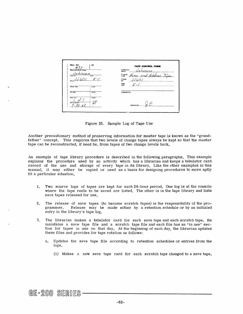
REEL NO. I OF
1-7J'
Joe NO. UNIT
.1)(,01 E-/
SEQ. ;0. of /
OA7_SJ~ .G2
I""
TAPE CONTROL FORM
Customers J I Name _~~Q~6~nL..S-""=oLL."-_c--__ _ P,og .. m j/ ~ /1 ,17 7::-: Code /Yame onc£ ,Hdc:lh?s-S" to"" ~~"g, ~~-------
COMMENTS:
OPERATOR_-b'Q~(f~ __
Figure 25. Sample Log of Tape Use
Another precautionary method of preserving information for master tape is known as the "grandfather" concept. This requires that two levels of change tapes always be kept so that the master tape can be reconstructed, if need be, from tapes of two change levels back.
An example of tape library procedure is described in the following paragraphs. This example explains the procedure used by an activity which has a librarian and keeps a tabulator card record of the use and storage of every tape in its library. Like the other examples in this manual, it may either be copied or used as a basis for designing procedures to more aptly fit a particular Situation.
1. Two source logs of tapes are kept for each 24-hour period. One log is at the console where the tape reels to be saved are listed. The other is in the tape library and lists save tapes released for use.
2. The release of save tapes (to become scratch tapes) is the responsibility of the pro-grammer. Release may be made either by a retention schedule or by an initialed entry in the library's tape log.
3. The librarian makes a tabulator card for each save tape and each scratch tape. He maintains a save tape file and a scratch tape file and each file has an "in use" section for tapes in use on that day. At the beginning of each day, the librarian updates these files and provides for tape rotation as follows:
a. Updates the save tape file according to retention schedules or entries from the logs.
(1) Makes a new save tape card for each scratch tape changed to a save tape.
@[Eo~®® ~[E[ffi~[E~ ------------63-
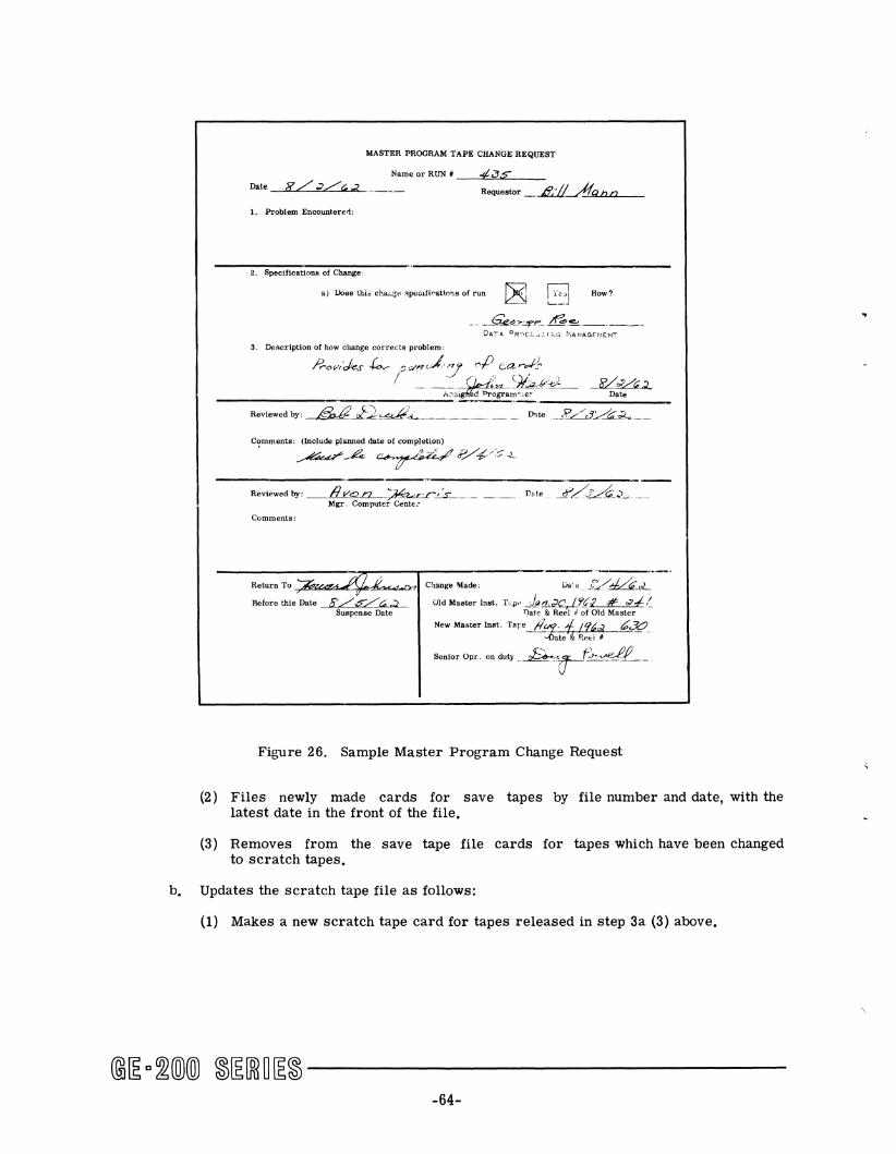
MASTER PROGRAM TAPE CRANGE REQUEST
Name or RUN t _--=4~a",s=,,--__ Requestor _~---.Aq .... bu..c..n,--_
1. Problem Encountered:
2. Specifications of Change,
a) Does thi& chw:..ge 3pecJ.fi<-attons of run ~ How?
-- -~~?:2f'.-.- ~.~.--.---DA.TA CR'iCE. .... .3 r i\.G t':ANAGrr-1ENT
3. Description of how change corrects problem:
;:;'OVI'ckS ~:;C/I?J.'n'l <,P card}. I . __ ~ (1-I~9i~~.€*_ -E(~
___________ -:':"" _____ .;;A.;;o.'~Ogram".;er Date
Reviewed by, ~-.al2:~.!l....-----_- _ _ D'te __ PL.5~C;_?_.. __ .
Comments: (Include planned date of completion)
. ~A C!.rh~e/~./-';:-<-
Reviewed by: Ilv<!:> n ;~~. ___ .. Date 1L.TA_,)~ ... __ Mgr. Computer Cente.:
Comments:
Return To~ ~~'_Z;,w.a;q7..~il4-"""-"'""'-.~:¥11 Change Made,
,£/p-,:;,;) Old Master Inst. T~pe J~!1,.Jf4.l.l.(2 #= ~-I,~ Before this Date Suspense Date T)ate & Reel it of Old Master
New Master Inot. Tare. /1.ur- 1. /'l~ ~30_ ~te""'&P..P'6i*
Senior Opr. on duty _~~:....d..f_._
Figure 26. Sample Master Program Change Request
(2) Files newly made cards for save tapes by file number and date, with the latest date in the front of the file.
(3) Removes from the save tape file cards for tapes which have been changed to scratch tapes.
b. Updates the scratch tape file as follows:
(1) Makes a new scratch tape card for tapes released in step 3a (3) above.
-64-
..
(2) Files updated scratch tape cards behind the remainder of the cards in the file so as to provide for rotation.
(3) Places cards corresponding to the scratch tapes used the previous day in the back of the scratch tape file.
c. Preselects all tapes for the console operation for the day's shifts and places these cards in the in-use section of the file. Scratch tapes are taken to correspond to the first cards in the scratch tape file.
d. After the card files are completely updated for the day, makes a complete tabulated listing of the cards including the in-use file.
The retention schedule mentioned in step 3a above is a schedule used with production-run tapes, The schedule lists data numbers which identify a reel as containing a certain kind of data. Depending on the kind of data, the reel must be kept a specified number of days after the save tape was originated,
If the librarian is absent. the senior operator selects scratch-tape reels corresponding to the cards in the front of the scratch-tape card file and places the cards in the in-use section of the file,
Replacing Photosense Markers
New tape has reflective photosensing markers at specified distances from either end of the tape. The marker at the leader end of the tape, called a "load point marker," provides a "leader interlock," so that depressing the REVERSE or REWIND button (after tape is beyond the leader foil) causes tape to move back only as far as the load point marker. This prevents the tape from moving off the takeup reel. Another function of the leader foil is to position the tape after a high- I speed rewind. The tape runs backward at high speed, slows down before it reaches the marker, and stops on the marker. The marker near the end of the reel is called the trailer marker. It provides a "trailer interlock," so that depressing the FORWARD button causes tape to move only as far as the marker. This prevents the tape from running off the supply reel. (The programmer can program around the trailer foil if he chooses.) These leader and trailer foils do not normally come off or even get loose at the corners. However, it can happen that a marker needs to be moved or replaced. For example, the marker must be placed farther from the end of the tape when an end of tape becomes worn. The worn part may be cut off when this happens.
The photosensing markers themselves are of reflective foil with an adhesive base. Each marker should be one inch long and 0,2 inches wide. Markers are available in rolls of 250 markers each, Markers can also be cut from a large flat piece of the reflective material. The markers should be placed parallel to the edge of the tape and not more than 1/32 inch from the edge. No portion should extend beyond the edge of the tape, and the adhesive material should not extend beyond the edges of the marker, Markers can best be added to tape when the reels are mounted on the tape handlers. The importance of the positioning of the markers can be understood when one looks at the senSing cells in the leader sensor (see Figure 24). Each
@j~ c~(Q)(ID ~~[ffiO~~ ------------65-
I
leader and trailer foil must pass under its respective sensing cell. Markers are to be placed as follows (tapes are assumed to be mounted on a tape handler):
1. Load Point Marker. Place marker 15 to 25 feet from the beginning end of the tape, on the shiny side, and 1/32 inch from the edge farthest from the handler deck and closest to the operator.
2. Trailer Marker. Place 32 to 35 feet from the end of tape, on the shiny side, and 1/32 inch from the edge nearest the handler deck and farthest from the operator.
Cleaning and Care of Tape Handlers
It is important that tape handlers be kept clean and free of dust and other extraneous particles. The service engineers for each site specify the exact procedures to be followed in the care of tape handlers and specify how much of the cleaning process must be done by the operators. The frequency of required routine cleaning depends, of course, upon the amount of tape use. The following list suggests the procedures necessary in the cleaning process, but it is not intended to replace instructions by the service engineer.
1. Clean the read-write heads with disposable tissue wiper or lint-free cloth dampened with an approved head cleaner. Wipe the head area until all of the dust particles are removed.
2. Look for bits or slices of tape or an excessive collection of caked oxide in any of the handler area. This could mean that flaws or burrs are developing on some of the surfaces where the tape travels. When this occurs, call the service engineer.
3. Wipe all surfaces over which where the tape travels (except the pressure pads on models which have pressure pads) with a disposable tissue wiper or lint-free cloth dampened with denatured alcohol. Remove all oxide and dust particles, making sure no caked oxide is left in corners of tape guides.
4. Use a Q-Tip to clean the glass cover over the lamp and photodiodes on the photosense head.
Inspection and Replacement of Damaged Tape
It is very unlikely that tape with a polyester base could ever break, but it can stretch. During unusual circumstances, tensions developed by the handler may be enough to damage a section of the tape beyond repair. Some more common forms of damage are scratched surface of the oxide; creased tape, where the plastiC itself shows damage; and minor stretching of the tape which may be visible as oxide coming loose or flaking. Usually, the wear occurs first on the leading end of the tape. When this happens, the end may be cut off and new leader foil placed on the tape. Before the end of the tape is cut, the operator should, of course, make sure that there is no needed data on the portion of tape to be discarded. Never attempt to splice a tape. If a stretched or otherwise damaged portion of tape is found in the center portion of a reel, the tape may be split onto two reels.
@~D~®® ~~[ffi~~~------------66-
As tape is used, its repeated passing over the read and write heads will gradually wear tracks in the oxide. These tracks are to be expected and are of no real concern until the wear becomes severe enough to cause parity errors. Eventually, there will come a time when the tape is either too short or is worn sufficiently to cause frequent read or write errors, and must be discarded altogether. At this time, all needed data must be moved to a new tape, and the old tape can be thrown away.
If a tape becomes creased, stretched, or broken such that needed data cannot be read, it may be necessary that the missing data be obtained by reconstructing the tape from the original tapes or other input media. The run book or the programmer should specify whether the operator should bypass the portion of the tape and reconstruct the data later or whether the run should be stopped at the point where the tape cannot be read.
Care of Magnetic Tape
Condition of tape has a critical effect on the operational reliability of a magnetic tape system. The operating environment in which tape is used should be within the temperature limits of 65 F to 90 F and relative humidity limits of 40 percent to 60 percent. The useful life of the tape depends greatly on its handling and storage. Negligence can cause tape to deteriorate relatively fast, while careful handling and storage can do much toward achieving its maximum useful life. Naturally, there is a right way and a wrong way for handling tape. Cigarette ashes and poor housekeeping practices can cause more tape trouble than does equipment failure. The following tape handling and storing procedures should be learned and practiced.
HANDLING MAGNETIC TAPE.
1. Handle reels of tape carefully. Do not press reel edges together; this could cause damage both to the reel and to the tape on the reel. Do not drop the reels. Do not touch the sides of the tape pack on the reel.
2. Do not touch the oxide (dull-finished) side of the tape where information may be written, for oil from one's fingers can damage the surface.
3. Do not handle the tape such that it can be creased in any way.
4. Do not allow any part of the tape, including the leader, to unravel and touch any surface, - -not even a table top, and especially not the floor. Electrostatic charges on the tape attract dust particles.
5. Do not put the tape on a handler unless all tape travel areas (guides, heads, capstans) are clean and completely dry.
Make sure that the write-permit ring, when used, is pressed all the way into the slot on the reel. An improperly seated ring may rub the write-permit switch and produce plastic powder which falls onto the handler and tape.
7. On nonvacuum feed models, be careful never to touch the pressure pads. If these become soiled or out of tolerance, they allow the tape to creep and cause parity errors.
-67-
8. Never spin the tape off the leader under power, for it cracks the tape; the flakes which come off the tape stay on the area of the read head where they may later cause damage.
9. Occasionally inspect tape for wear and for damage. Tbl •• baWd be done with the reel mounted so that, as the tape is inspected, it can be wound onto another reel.
10. When leaders become tightly curled, trim them off to make loading easier.
STORING MAGNETIC TAPE
1. Always have reels of tape in containers when they are removed from the tape handler mounts. Do not press the sides of the reel so that they make contact with the tape, since the tape may not be evenly wound and the edges could be damaged.
2. Never place uncased reels of tape on a dusty surface.
3. Keep the inside of tape containers clean,
4. Store tapes where conditions are as follows:
a. Free from dust and dirt.
b, Temperature range between 40 and 90 degrees Fahrenheit.
c. Relative humidity between 20 and 80 percent.
d. Free from magnetic fields such as those caused by motors, heavy power lines, and magnets.
5, When tape has been subjected to temperature and humidity conditions outside the prescribed limits, it must be reconditioned before use. This is done by removing the top of its case, but protecting the reel from dust, while exposing it to machine room conditions of proper temperature and humidity, It must be reconditioned in this way for double the length of time of improper exposure, not exceeding 24 hours.
6. Store tapes in their container in a rack vertically (the containers stand on edge). Avoid stacking tapes horizontally, for this could cause reel warpage.
7. Store tapes which contain information to be saved in a separate place from those which have no usable information on them, Be sure that all tapes to be saved are stored with the write-permit ring removed.
OPERATOR CORRECTIVE ACTION
During magnetic tape operations, it is important that any difficulty in running the program be quickly diagnosed. Operational difficulties can be caused by errors made by the operator or by errors in the program. The following information is presented to assist the operator in classifying errors. Figure 28, at the end of this section, summarizes alert conditions and their possible causes; it also suggests operator corrective action for each type of alert.
@~D~(Q)(ID ®~[ffin~® ------------68-
OPERATOR CHECKPOINTS
The magnetic tape system can fail to operate properly or a program can fail to run when the operator neglects to:
1. Load tape correctly. 2. Rewind tape when required. 3. Install write-permit ring when trying to write tape. 4. Set the rotary address selector switch on tape handler to the correct number. 5. Put tape handler on remote control, 6. Connect correct controller selector channel. 7. Make sure that no two handlers are set to the same number.
PROGRAM CHECKPOINTS
Although the program is the responsibility ofthe programmer and not the operator, it is important that the operator recognize program alerts when they occur. For this reason, the following program information is reviewed. As in all operations involving use of the controller-selector, the peripheral must first be selected by controller selector channel number before it can respond to an instruction. The service engineer must connect the tape controller to the correct channel. Instructions RTD, RTB, ERT, RTS, RBD, RBB, RBS, RWD, WTD, WTB, WTS, WEF, and BKW must be preceded by the SE L P (P being the channel number) instruction. The specific instruction must be accompanied by the tape handler number (switch setting on the tape handler control panel).
If the programmer has not put in needed instructions--for example, to rewind the tape, write end-of-file characters, backspace, or branch--the program will not run correctly. If extra instructions must be inserted, it is necessary to return the program to its originator with a notation of the contents of the P-counter and the I-register where the program stalled. Routines are usually programmed to instruct the tape controller to try to reread or rewrite several times when an alert occurs. If this fails, the controller "gives up," the program halts, and the operator must take over. In some cases it is possible to recover after the cause of the alert has been corrected. The decision to restart or recover a program should be based on restart procedure in the run book or other programmer instructions.
When the operator cannot proceed with the running of the program because of an error condition, he should make note of the status of various indicators and registers. He should give this information along with explanatory information to the programmer if he thinks there was a program error and to the service engineer if he thinks the equipment caused the error. Figure 27 shows a form which has been found useful in recording information from the magnetic tape controller and the console of the central processor.
-69-

HANG-UP SHEET
NAME OR
Po s t,',-,g, Run HUN # DATE Y;~~~ ___ _ _--,b=c...' -"e_-"C:A)~""J.L.n,",e;;.;s>-- PHOGHAMMER TIME _---'/--=:/~3.""(? _____
Caution: Be sure all information has been recorded before taking ml.!nlory dump.
~ ALERT HALT
o BHANCH HALT
~ LOOP (Try to give the Branches)
Hemarks:
BCD MUDE
On Uff
o l8J
QLIGHT ON
o Ready
ON Beg
~Lateral Parity
CONSOLE
1------- - 'r-- -n::·11''''i, :;;-:il~~.~;;-;il
U~-H--[; ~'~-U:~-lJ
TAPE CONTlWLLEH
( x LIGHT ON)
o End of File
~Alert Last Hecurrl
(lllurizont:tl Parity
A CO coo coo COO C,---C
i8:)Akrt
ol\lenlOl'Y Akrt
~j()1l
O,\krt
I' ~ , U
o I 2 3 • ~ 6 , 8 ~ >L' " ,,:: ,} I. ,~ 0;
Ox For Switch Down
SENSE SWITCH
Q 00000000 COO 000 08000 000 000 OOO:aOO~~O
H UNNING TIME _--"VLO"",--./.!!)fl,-,-,--,,'n,--,-,--, __ OPERATOR
Figure 27. Sample Indicator Sheet
-70-

Alert Condition Possible Cause Operator Corrective Action
CONTROL CONSOLE INDICATORS Nonexistent controller Check controller-selector channel ECHO ALARM on the GE-200/ is addressed. number, have service engineer install 215/225 or the CONT SEL correct channel connection; return alarm on the GE-235 glows program to originator if condition red. cannot be corrected.
Busy controller is Return program to originator for addressed. program correction.
TAPE CONTROLLER INDICATORS Tape handler is addressed Set REMOTE/LOCAL switch to REMOTE and ALERT HALT indicator glows while in local control or turn on power; press controller CLEAR blue. power is off. button and return to nearest rerun
point.
Tape is broken or If leader is broken, put new reflector stretched. load point marker 15 to 25 feet from
beginning of tape; if break is in record sections, data may require rewriting on new tape.
Tape not loaded on Load tape on addressed handler or handler. switch to handler that is loaded.
Dust cover on tape handler Release latch and close dust cover. is open (in latched posi-tion).
Writing was attempted with Install write-permit ring on tape suppl write-permit ring removed reel. from reel.
Nonexistent tape handler Set rotary address selector switches rotary address selector to correct numbers; if progrannner switch was addressed or error, return program to originator. switches not set correctly.
Tape handler addressed Return program to originator for while rewinding because programmer correction. delay loops not programmed.
Reading in reverse or Return program to programmer with note rewind was attempted while on required revision; if inadvertently on the leader. rewound by operator, correct and rerun.
Figure 28. Magnetic Tape Subsystem Alert Conditions
@~D~(QXID ~~[ffi~~~-----------
-71-
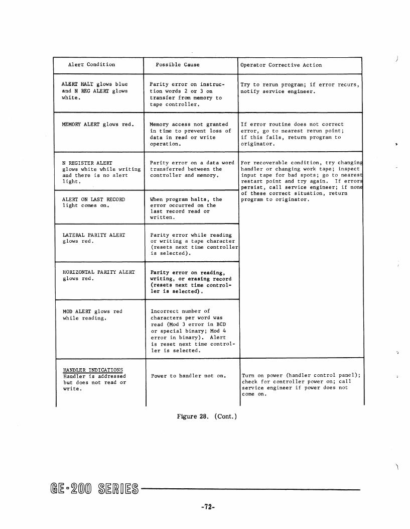
Alerr Condition
ALERT HALT glows blue and N REG ALERT glows white.
MEMORY ALERT glows red.
N REGISTER ALERT glows white while writing and there is no alert light.
Possible Cause
Parity error on instruction words 2 or 3 on transfer from memory to tape controller.
Memory access not granted in time to prevent loss of data in read or write operation.
Parity error on a data word transferred between the controller and memory.
Operator Corrective Action
Try to rerun program; if error recurs, notify service engineer.
If error routine does not correct error, go to nearest rerun point; if this fails, return program to originator.
For recoverable condition, try changinE handler or changing work tape; inspect input tape for bad spots; go to nearest restart point and try again. If erron
~ __________________________ ~ ______________________________ ~persist, call service engineer; if none of these correct situation, return program to originator. ALERT ON LAST RECORD
light comes on.
LATERAL PARITY ALERT glows red.
HORIZONTAL PARITY ALERT glows red.
MOD ALERT glows red while reading.
HANDLER INDICATIONS Handler is addressed but does not read or write.
When program halts, the error occurred on the last record read or written.
Parity error while reading or writing a tape character (resets next time controller is selected).
Parity error on reading, writing, or erasing record (resets next time controller is selected).
Incorrect number of characters per word was read (Mod 3 error in BCD or special binary; Mod 4 error in binary). Alert is reset next time controller is selected.
Power to handler not on.
Figure 28. ( Cont. )
Turn on power (handler control panel); check for controller power on; call service engineer if power does not come on.
@~ c ~(Q)(ID ~~[Ri~[E~ -----------
-72-
)
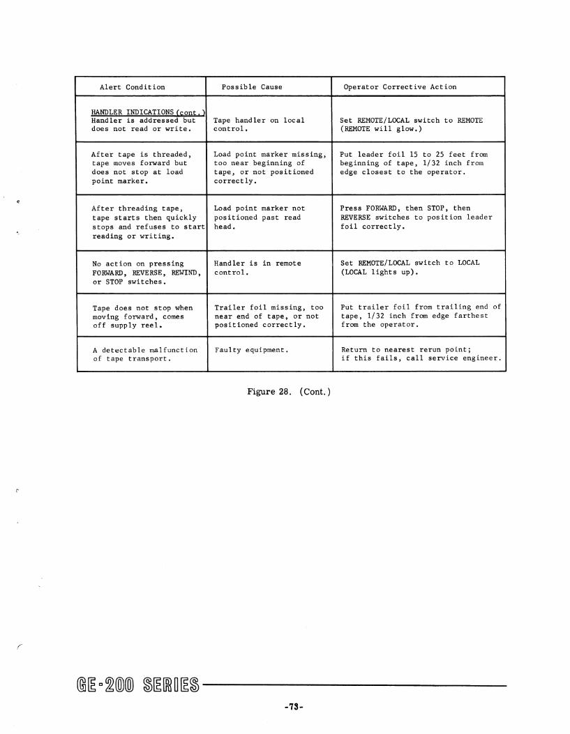
Alert Condition Possible Cause Operator Corrective Action
HANDLER INDICATIONS'~oDtl} Handler is addressed but Tape handler on local Set REMOTE/LOCAL switch to REMOTE does not read or write. control. (REMOTE will glow.)
After tape is threaded, Load point marker missing, Put leader foil 15 to 25 feet from tape moves forward but too near beginning of beginning of tape, 1/32 inch from does not stop at load tape, or not positioned edge closest to the operator. point marker. correctly.
e After threading tape, Load point marker not Press FORWARD, then STOP, then tape starts then quickly positioned past read REVERSE switches to position leader stops and refuses to start head. foil correctly. reading or writing.
No action on pressing Handler is in remote Set REMOTE/LOCAL switch to LOCAL FORWARD, REVERSE, REWIND, control. (LOCAL lights up). or STOP switches.
Tape does not stop when Trailer foil missing, too Put trailer foil from trailing end of moving forward, comes near end of tape, or not tape, 1/32 inch from edge farthest off supply reel. positioned correctly. from the operator.
A detectable malfunction Faulty equipment. Return to nearest rerun point; of tape transport. if this fails, call service engineer.
Figure 28. ( Cont. )
-73-

)

APPENDIX A.
INSTRUCTION TIMES
OPERAND M Memory Location - starting address N Length of record (number of words) P Channel Number (Priority Control)
General Assembly Program Symbol X T Tape Handler Number P Channel Number (Priority Control)
Times in /Jsec. Opr Operand X Octal 200 215 225 235
r BCS BEF P 2514P21 36 72 36 24/36
BCS BER P 2514P27 36 72 36 24/36
BCS BET P 2514P22 36 72 36 24/36
BCS BIC P 2516P25 36 72 36 24/36
BCS BIO P 2514P25 36 72 36 24/36
BCS BME P 2514P26 36 72 36 24/36
BCS BNE P 2516P27 36 72 36 24/36
BCS BNF P 2516P21 36 72 36 24/36
BCS BNM P 2516P26 36 72 36 24/36
BCS BNR P 2516P23 36 72 36 24/36
BCS BNT P 2516P22 36 72 36 24/36
BCS BPE P 2514P24 36 72 36 24/36
BCS BPC P 2516P24 36 72 36 24/36
BCS BRW P 2514P23 36 72 36 24/36
BCS BTN P 2516P20 36 72 36 24/36
BCS BTR P 2514P20 36 72 36 24/36
BKW T 1600000 36 72 36 36
ERT T 1300000 36 72 36 36
RBB M T 15MMMMM 36 72 36 36
RBD M T 14MMMMM 36 72 36 36
RBS M T 35MMMMM 36 72 36 36
RTB M T 05MMMMM 36 72 36 36
RTD M T 04MMMMM 36 72 36 36
RTS M T 25MMMMM 36 72 36 36
RWD T 2000000 36 72 36 36
SEL P 2500P20 36 72 36 24/36
WEF T 0200000 36 72 36 36
WTB M T 03MMMMM 36 72 36 36
WTD M T 02MMMMM 36 72 36 36
WTS M T 23MMMMM 36 72 36 36
(
@[g Q~(ID(ID ~[g[ffi~[g~ -------------75-

)
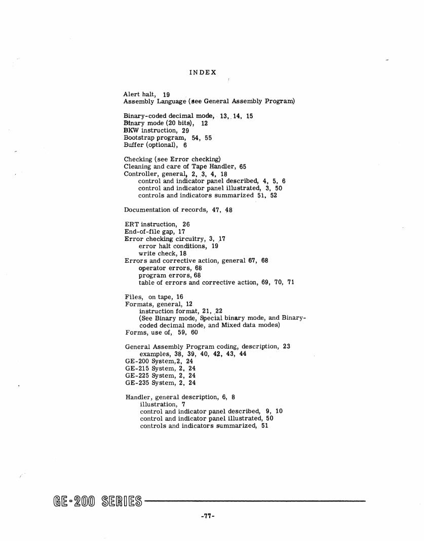
(
INDEX
Alert halt, 19 Assembly Language (see General Assembly Program)
Binary-coded decimal mode, . 13,. 14, 15 Binary mode (20 bits), 12 BKW instruction, 29 Bootstrap program, 54, 55 Buffer (optional), 6
Checking (see Error checking) Cleaning and care of Tape Handler, 65 Controller, general, 2,3, 4, 18
control and indicator panel described, 4, 5, 6 control and indicator panel illustrated, 3, 50 controls and indicators summarized 51, 52
Documentation of records, 47, 48
ERT instruction, 26 End-of-file gap, 17 Error checking circuitry, 3, ,17
error halt conditions, 19 write check, 18 .
Error s and corrective action, general 67, 68 operator errors, 68 program errors, 68 table of errors and corrective action, 69, 70, 71
Files, on tape, 16 Formats, general, 12
instruction format, 21, .22 (See Binary mode, Special binary mode, and Binarycoded decimal mode, and Mixed data modes)
Forms, use of, 59, 60
General Assembly Program coding, description, 23 examples, 38, 39, 40, 42, 43, 44
GE-200 System,2, 24 GE-215 System, 2, 24 GE-225 System, 2, 24 GE-235 System, 2, 24
Handler, general description, 6, 8 illustration, 7 control and indicator panel described, 9, 10 control and indicator panel illustrated, 50 controls and indicators summarized, 51
@~a~@@ ~~[R1U~~------------'1'1-
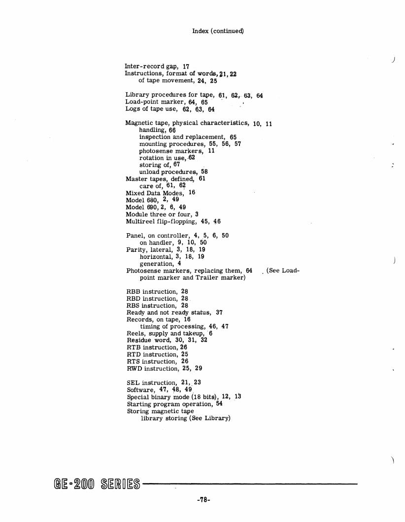
Index (continued)
Inter-record gap, 17 Instructions, format of words, 21,22
of tape movement, 24, 25
Library procedures for tape, 6,1, 62,. 63, 64 Load-point marker, 64, 65 Logs of tape use, 62, 6.3, 64
Magnetic tape, physical characteristics, 10, 11 handling, 66 inspection and replacement, 65 mounting procedures, 55, 56, 57 photosense markers, 11 rotation in use, ,62 storing of, 67 . unload procedures, 58
Master tapes, defined, 61 care of, 61, 6?
Mixed Data Modes, 16 Model 680, 2,49 Model 690,2, 6, 49 Module three or four, 3 Multireel flip-flopping, 45, 46
Panel, on controller, 4,5, 6, 50 on handler, 9, 10, 50
Parity, lateral, 3, 18, 19 horizontal, 3, 18, 19 generation, 4
Photosense markers, replacing them, 64 . (See Loadpoint marker and Trailer marker)
RBB instruction, 28 RBD instruction, 28. RBS instruction, 28 Ready and not ready status, 37 Records, on tape, 16
timing of processing, 46, 47 Reels, supply and takeup, . 6 Residue word, 30, 31, 32 RTB instruction, 26 RTD instruction, 25 RTS instruction, 26 RWD instruction, 25, 29
SEL instruction, 21,.23 Software, 47, 48, 49. Special binary mode (18 bits), 12, 13 Starting program operation, 54 Storing magnetic tape
library storing (See Library)
@~a~@@ ~~[ffi~~~------------78-
)

(
Index (continued)
Switches, on controller, 6 on handlers, 9, 10
System configuration, 1,2
Tape (See Magnetic tape) Test and braJ'ch instruction, descriptions, 19, 33
34, 35, 36 examples of use, 37, 38, 39
Trailer marker, 11, 64, 65
WEF instruction, 26, ,45 Write check (See Error checking) Write permit ring, .18 WTB instruction, 25 WTD instruction, 25 WTS instruction, 25
@~D~®® ~~[Ri~~~------------79-

)
)

)
LITHO U.8.~.