Embed Size (px)
Citation preview

K.P.
B.A.N.
1 : 75
or as shown
2
GENERAL ELEVATION
130
1.5% 1.5% 38
Asphalt overlay
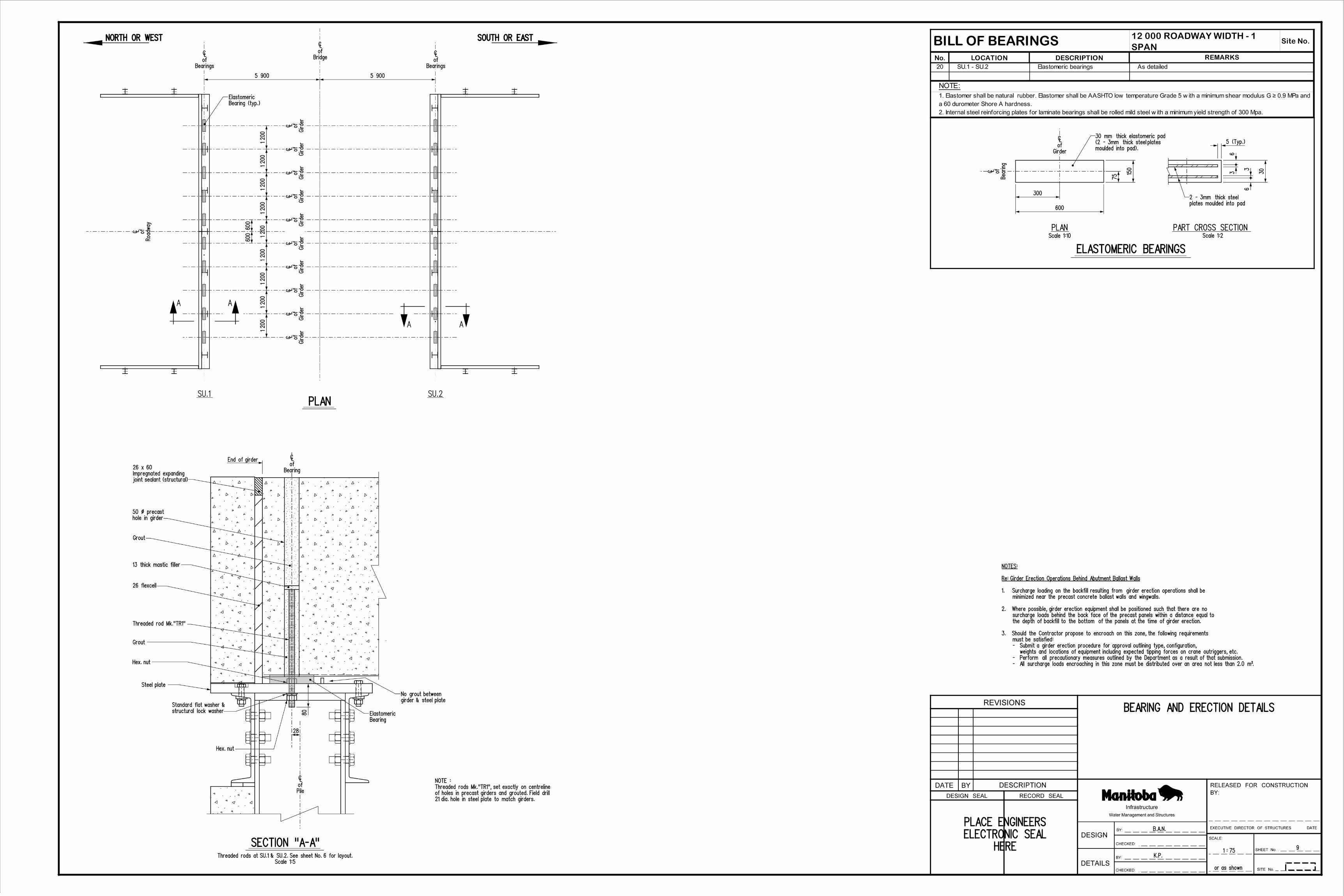
NORTH OR WEST SOUTH OR EAST
Scale 1:50
3:1 3:1
HERE
ELECTRONIC SEAL
PLACE ENGINEERS
@ | of roadway
Elev. m
Final pavement
@ | of roadway
Elev. m
Final pavement
__ m long
HP 310 x 110,
Steel piles
__ m long
HP 250 x 85,
Steel piles
__ m long
HP 250 x 85,
Steel piles
__ m long
HP 310 x 110,
Steel piles
ELEVATION
PLAN
CROSS SECTION
concrete channel girders
650 deep precast prestressed
Final pavement Elev.
Roadway
of
|
250 x 85
Steel H-Piles
250 x 85
Steel H-Piles
250 x 85
Steel H-Piles
250 x 85
Steel H-Piles
5 8725 872
2 500 1 560 2 5001 560
2 500 1 560 2 5001 560
6 000 6 000
12 000
10 girders @ 1 200 = 12 000
830
3 Spaces
@ 2 10
0 = 6 300
3 Spaces
@ 2 10
0 = 6 300
830
830
3 Spaces
@ 2 10
0 = 6 300
3 Spaces
@ 2 10
0 = 6 300
830
Ste
el
H-Piles 310 x 110
Ste
el
H-Piles 310 x 110
12 352 out to out of precast backwall panels
Precast panel
Steel pile
1 000
max.
Granular backfill
Asphalt overlayPrecast panel
600
1 : 1
Scale 1:30
Typical at Su.1
SECTION A-A
AA
P.R.
No. ___
Road
way
of
|
Piles
of
|
Sta. __+__.___
Bridge
of
|
Piles
of
|
Elev. m
Pile cut-off
Elev. m
Pile cut-off
Elev. m
| of roadway
groundline along
Approx. existing
SU.2SU.1
200
BY:
RELEASED FOR CONSTRUCTION
REVISIONS
BYDATE
DESIGN
DETAILS
SHEET No.
SITE No.
SCALE:
BY:
CHECKED:
BY:
CHECKED:
DATE
DESCRIPTION
RECORD SEALDESIGN SEAL
Water Management and Structures
Infrastructure
EXECUTIVE DIRECTOR OF STRUCTURES
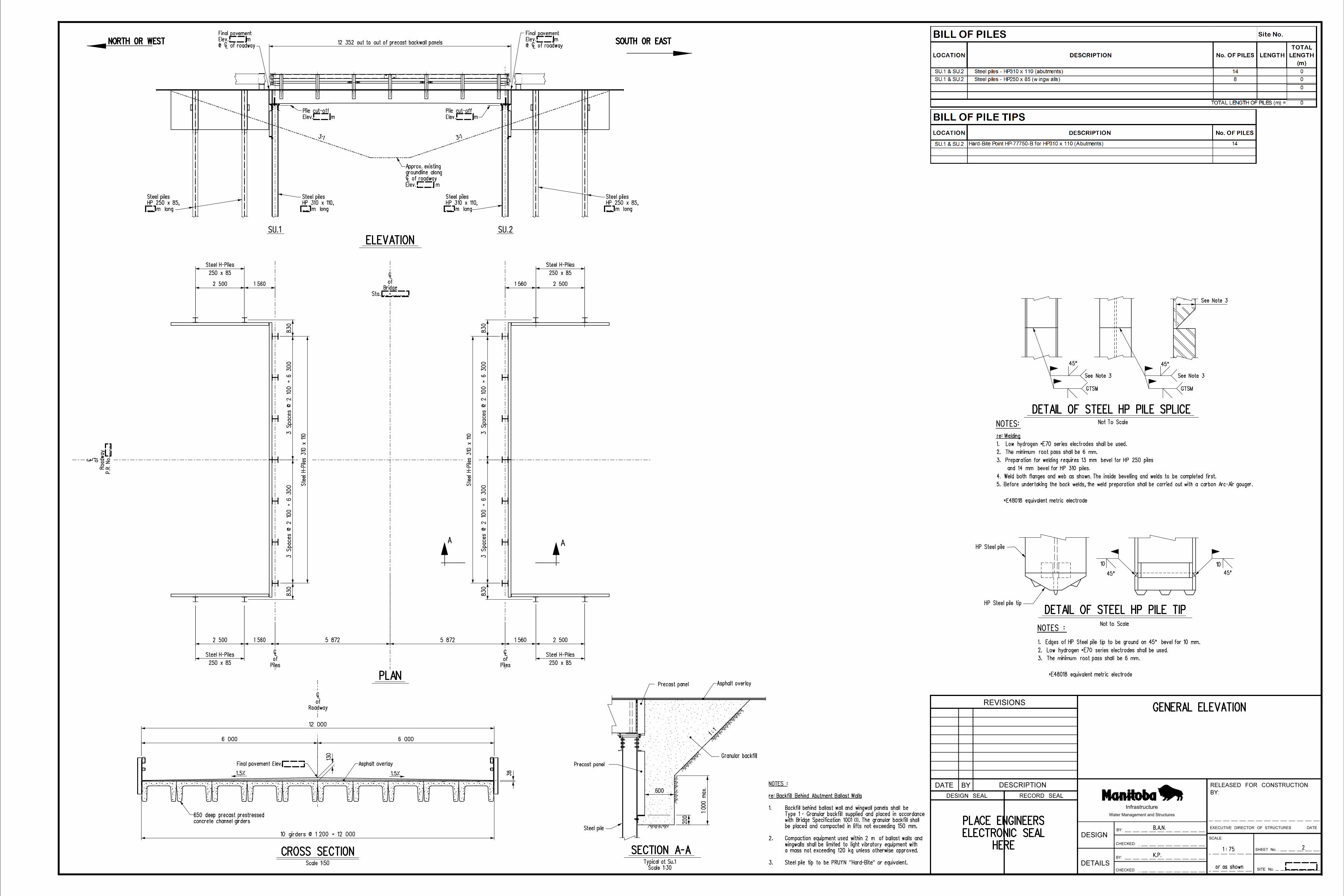
Steel pile tip to be PRUYN "Hard-Bite" or equivalent.3.
a mass not exceeding 120 kg unless otherwise approved.
wingwalls shall be limited to light vibratory equipment with
Compaction equipment used within 2 m of ballast walls and2.
be placed and compacted in lifts not exceeding 150 mm.
with Bridge Specification 1001 (I). The granular backfill shall
Type 1 - Granular backfill supplied and placed in accordance
Backfill behind ballast wall and wingwall panels shall be1.
re: Backfill Behind Abutment Ballast Walls
NOTES :
1010
45° 45°
NOTES :Not to Scale
HP Steel pile
DETAIL OF STEEL HP PILE TIPHP Steel pile tip
*E48018 equivalent metric electrode
3. The minimum root pass shall be 6 mm.
2. Low hydrogen *E70 series electrodes shall be used.
1. Edges of HP Steel pile tip to be ground on 45° bevel for 10 mm.
45°
See Note 3
GTSM
Not To Scale
45°
GTSM
See Note 3 See Note 3
NOTES:
*E48018 equivalent metric electrode
5. Before undertaking the back welds, the weld preparation shall be carried out with a carbon Arc-Air gouger.
4. Weld both flanges and web as shown. The inside bevelling and welds to be completed first.
and 14 mm bevel for HP 310 piles.
3. Preparation for welding requires 13 mm bevel for HP 250 piles
2. The minimum root pass shall be 6 mm.
1. Low hydrogen *E70 series electrodes shall be used.
re: Welding
DETAIL OF STEEL HP PILE SPLICE


K.P.1 : 200
or as shown
SITE AND EROSION CONTROL DETAILS
HEREELECTRONIC SEALPLACE ENGINEERS
NORTH OR WEST SOUTH OR EAST
NORTH OR WEST SOUTH OR EAST
Piles
of
|
Sta. __+__.___
Bridge
of
|
PLAN
ELEVATION
Elev. ___.___ m
Sta. __+__.___ m
Elev. ___.___ m
Sta. __+__.___ m
Sta. __+__.___
Bridge
of
|
Piles
of
|
4
Elev.______m
of channel
Proposed bottom
Rip rap
Elev.______m
summer high water level
Average annual
3:1
P.R.
No. ___
Road
way
of
|
Piles
of
|
Scale 1:75
SU.2SU.1
Piles
of
|
ADD SIT
E SP
ECIFI
C DIM
ENSIO
NS
GENE
RATE
SHEET F
ROM YOUR
SITE
PLAN
EXAMPLE L
AYOUT O
NLY
BY:
RELEASED FOR CONSTRUCTION
REVISIONS
BYDATE
DESIGN
DETAILS
SHEET No.
SITE No.
SCALE:
BY:
CHECKED:
BY:
CHECKED:
DATE
DESCRIPTION
RECORD SEALDESIGN SEAL
Water Management and Structures
Infrastructure
EXECUTIVE DIRECTOR OF STRUCTURES
UTILITY DISCLAIMER:
INDIVIDUAL UTILITIES BEFORE PROCEEDING WITH CONSTRUCTION.
THE EXISTENCE AND LOCATION OF UTILITIES BY OBTAINING FROM THE
OR THAT THE GIVEN LOCATIONS ARE EXACT. CONTRACTOR SHALL CONFIRM
INFORMATION. NO GUARANTEE IS GIVEN THAT ALL UTILITIES ARE SHOWN
LOCATIONS OF UTILITIES AS SHOWN ARE BASED ON READILY AVAILABLE
Existing pile bents to be removed by Bridge Contractor.
NOTE:
500
Geotextile
Geotextile
EDGE TREATMENT
OVERLAPPING DETAILS
FLOW
RIP RAP DETAILS
300
600
45°
Not To Scale
Class ___ rip rap
___ thick
2. Geotextile shall be placed under all rip rap, overlapping 600mm in direction of flow.
from the Manitoba Infrastructure's Approved Product List.
1. All geotextile shall be Non-Woven Geotextile, Class I (Heavy Duty)
NOTES:
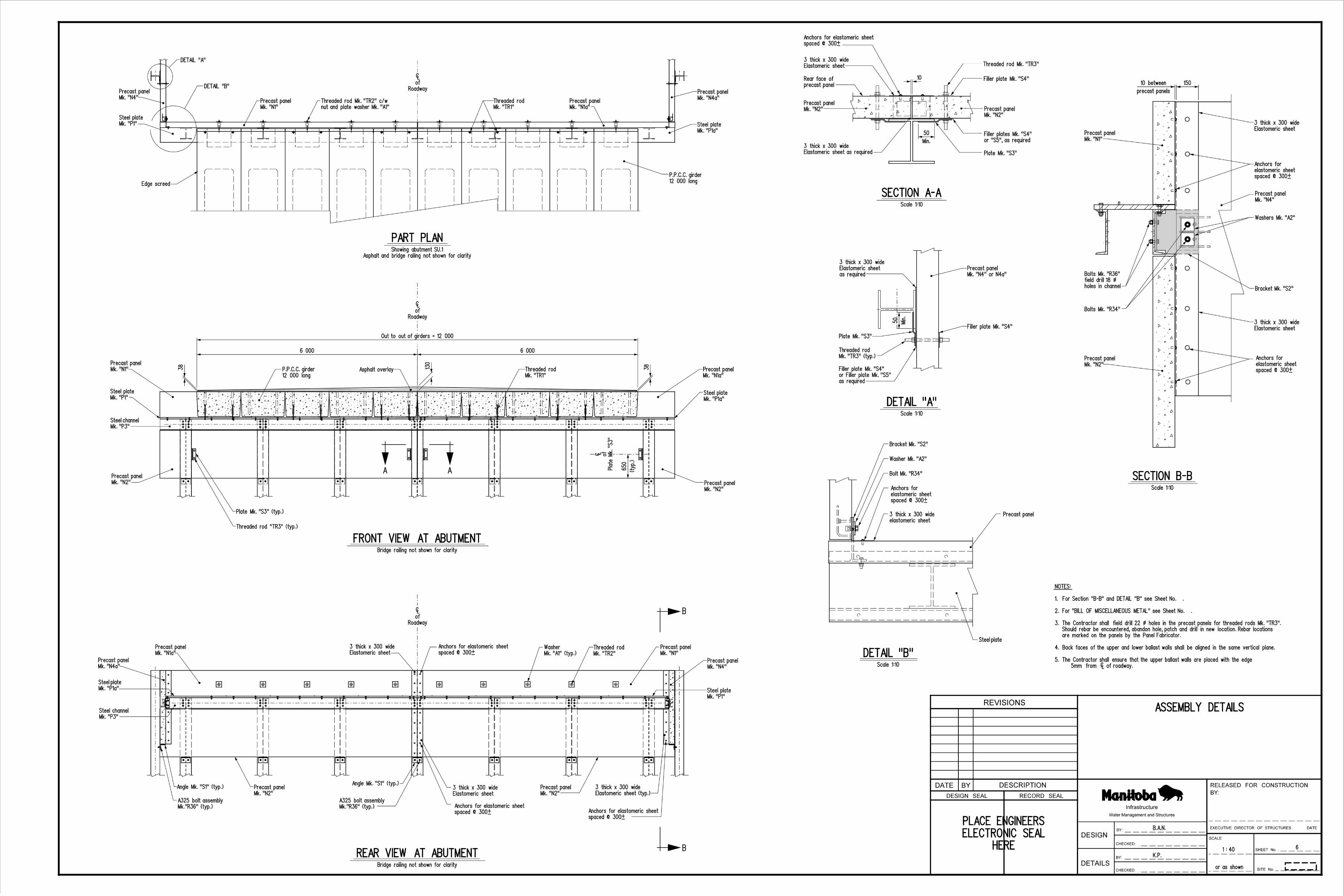
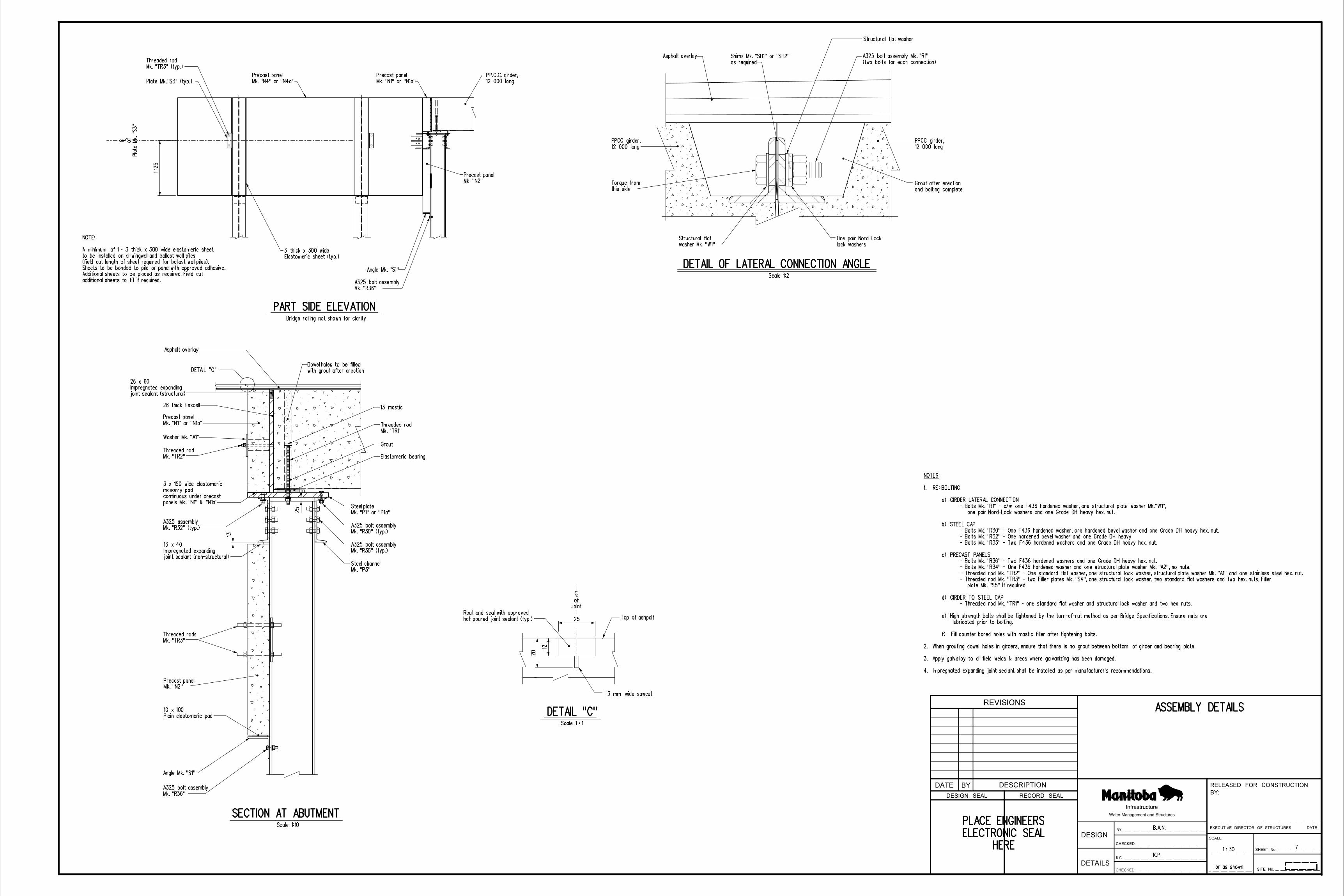
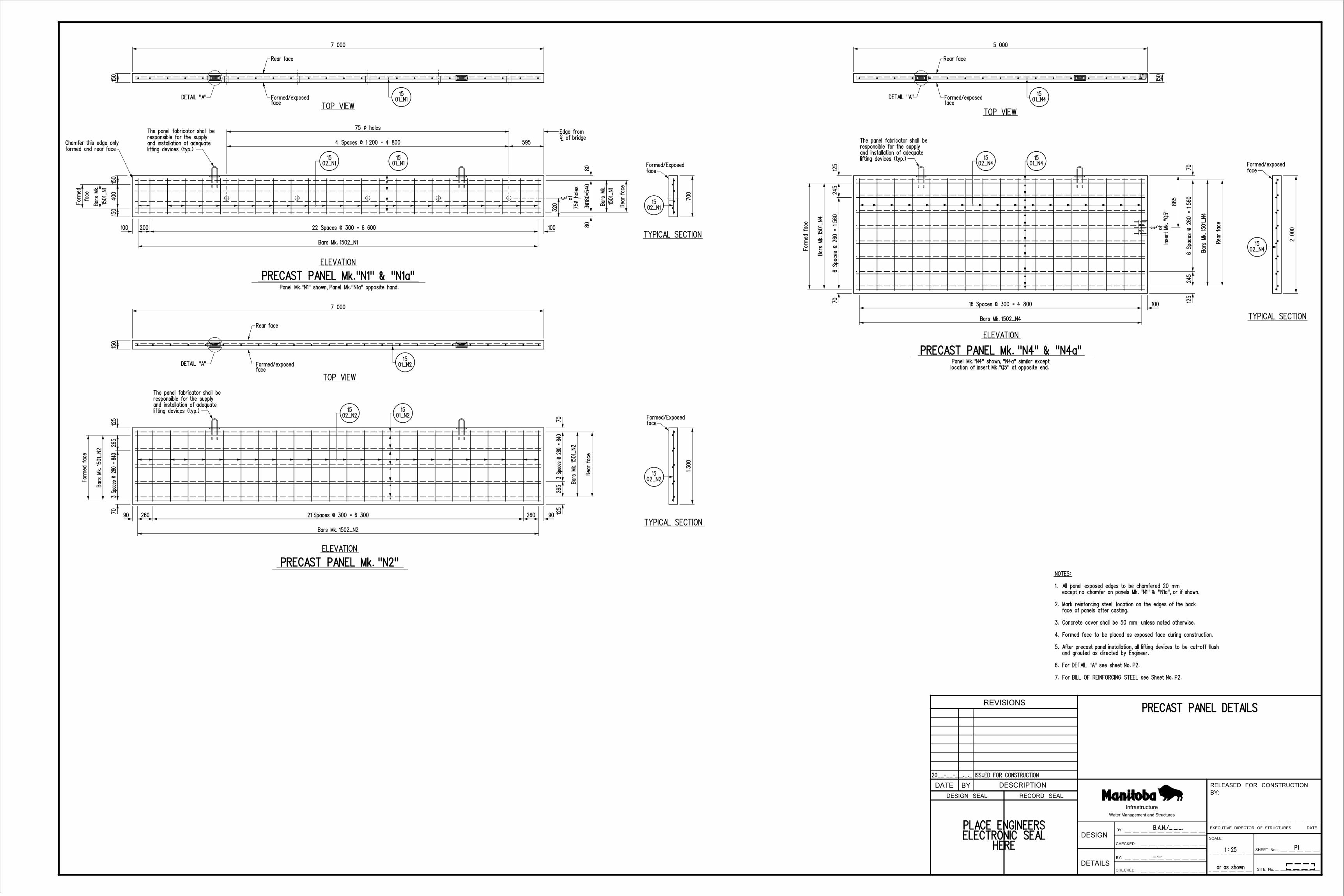
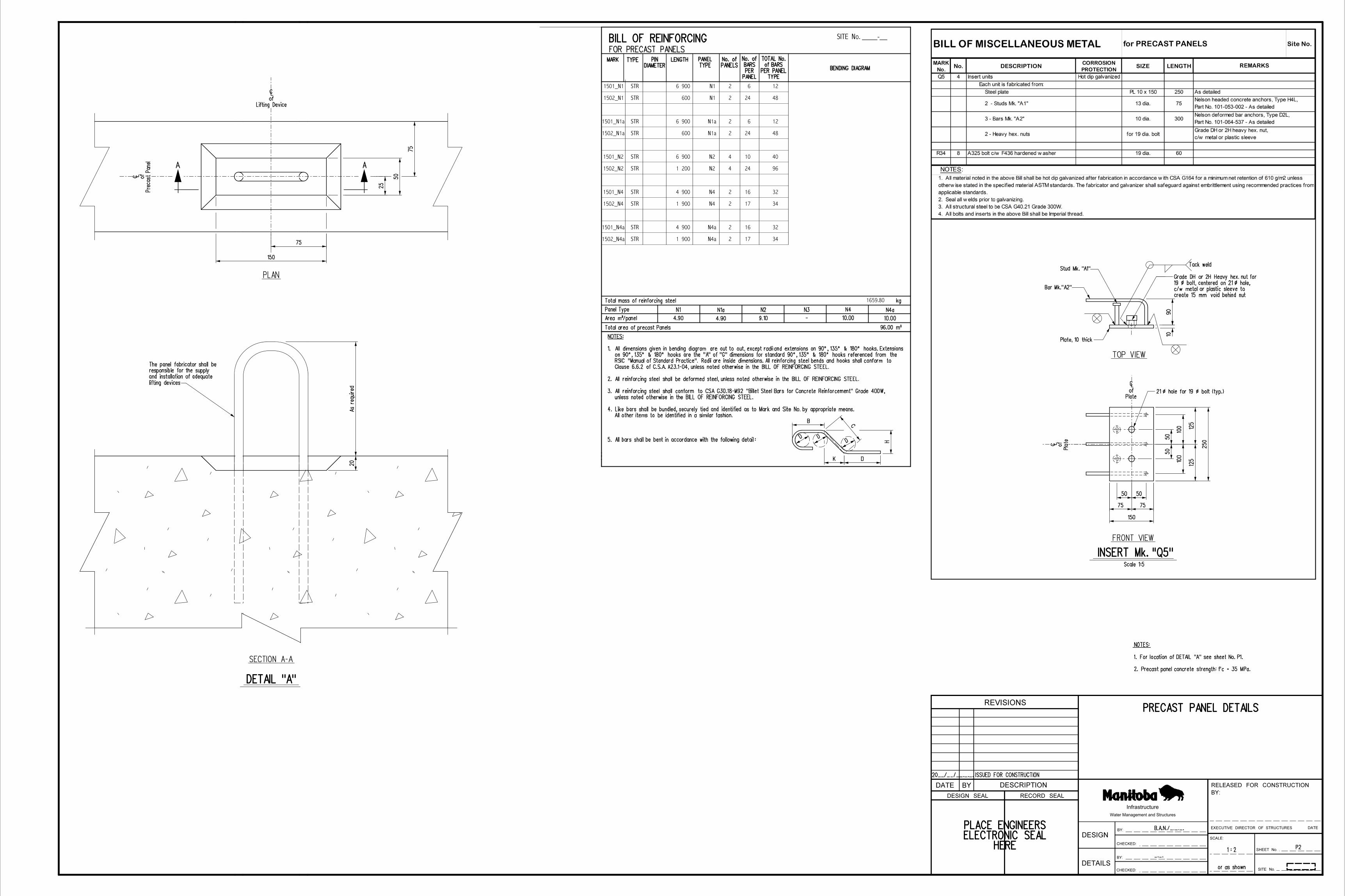
Mk. "N1" or "N1a"
Precast panel
12 000 long
PP.C.C. girder,
Mk. "N4" or "N4a"
Precast panel
Angle Mk. "S1"
Plate
Mk. "S3"
of
|
Bridge railing not shown for clarity
K.P.
B.A.N.
or as shown
ASSEMBLY DETAILS
1 : 30
Scale 1:10
Angle Mk. "S1"
Mk. "TR3"
Threaded rods
Mk. "TR2"
Threaded rod
Mk. "N1" or "N1a"
Precast panel
Washer Mk. "A1"
26 thick flexcell
Asphalt overlay
13
with grout after erection
Dowel holes to be filled
13 mastic
Mk. "TR1"
Threaded rod
Mk. "P1" or "P1a"
Steel plate
25
Scale 1:2
Asphalt overlay
12 000 long
PPCC girder,
and bolting complete
Grout after erection
12 000 long
PPCC girder,
this side
Torque from
lock washers
One pair Nord-Lock
as required
Shims Mk. "SH1" or "SH2"
Elastomeric bearing
Grout
Mk. "N2"
Precast panel
Mk. "N2"
Precast panel
HERE
ELECTRONIC SEAL
PLACE ENGINEERS
PART SIDE ELEVATION
DETAIL OF LATERAL CONNECTION ANGLE
SECTION AT ABUTMENT
Mk. "TR3" (typ.)
Threaded rod
Mk. "P3"
Steel channel
(two bolts for each connection)
A325 bolt assembly Mk. "R1"
Mk. "R36"
A325 bolt assembly
Mk. "R30" (typ.)
A325 bolt assembly
Mk. "R35" (typ.)
A325 bolt assembly
Mk. "R32" (typ.)
A325 assembly
DETAIL "C"
hot poured joint sealant (typ.)
Rout and seal with approved
Joint
of
|
3 mm wide sawcut
Top of ashpalt
DETAIL "C"Scale 1 : 1
Mk. "R36"
A325 bolt assembly
additional sheets to fit if required.
Additional sheets to be placed as required. Field cut
Sheets to be bonded to pile or panel with approved adhesive.
(field cut length of sheet required for ballast wall piles).
to be installed on all wingwall and ballast wall piles
A minimum of 1 - 3 thick x 300 wide elastomeric sheet
NOTE:
Elastomeric sheet (typ.)
3 thick x 300 wide
Structural flat washer
washer Mk. "W1"
Structural flat
joint sealant (structural)
Impregnated expanding
26 x 60
panels Mk. "N1" & "N1a"
continuous under precast
masonry pad
3 x 150 wide elastomeric
joint sealant (non-structural)
Impregnated expanding
13 x 40
Plain elastomeric pad
10 x 100
7
Plate Mk."S3" (typ.)
1 12
5
25
12
20
BY:
RELEASED FOR CONSTRUCTION
REVISIONS
BYDATE
DESIGN
DETAILS
SHEET No.
SITE No.
SCALE:
BY:
CHECKED:
BY:
CHECKED:
DATE
DESCRIPTION
RECORD SEALDESIGN SEAL
Water Management and Structures
Infrastructure
EXECUTIVE DIRECTOR OF STRUCTURES
4. Impregnated expanding joint sealant shall be installed as per manufacturer's recommendations.
3. Apply galvalloy to all field welds & areas where galvanizing has been damaged.
2. When grouting dowel holes in girders, ensure that there is no grout between bottom of girder and bearing plate.
f) Fill counter bored holes with mastic filler after tightening bolts.
lubricated prior to bolting.
e) High strength bolts shall be tightened by the turn-of-nut method as per Bridge Specifications. Ensure nuts are
- Threaded rod Mk. "TR1" - one standard flat washer and structural lock washer and two hex. nuts.
d) GIRDER TO STEEL CAP
plate Mk. "S5" if required.
- Threaded rod Mk. "TR3" - two Filler plates Mk. "S4", one structural lock washer, two standard flat washers and two hex. nuts, Filler
- Threaded rod Mk. "TR2" - One standard flat washer, one structural lock washer, structural plate washer Mk. "A1" and one stainless steel hex. nut.
- Bolts Mk. "R34" - One F436 hardened washer and one structural plate washer Mk. "A2", no nuts.
- Bolts Mk. "R36" - Two F436 hardened washers and one Grade DH heavy hex. nut.
c) PRECAST PANELS
- Bolts Mk. "R35" - Two F436 hardened washers and one Grade DH heavy hex. nut.
- Bolts Mk. "R32" - One hardened bevel washer and one Grade DH heavy
- Bolts Mk. "R30" - One F436 hardened washer, one hardened bevel washer and one Grade DH heavy hex. nut.
b) STEEL CAP
one pair Nord-Lock washers and one Grade DH heavy hex. nut.
- Bolts Mk. "R1" - c/w one F436 hardened washer, one structural plate washer Mk."W1",
a) GIRDER LATERAL CONNECTION
1. RE: BOLTING
NOTES:
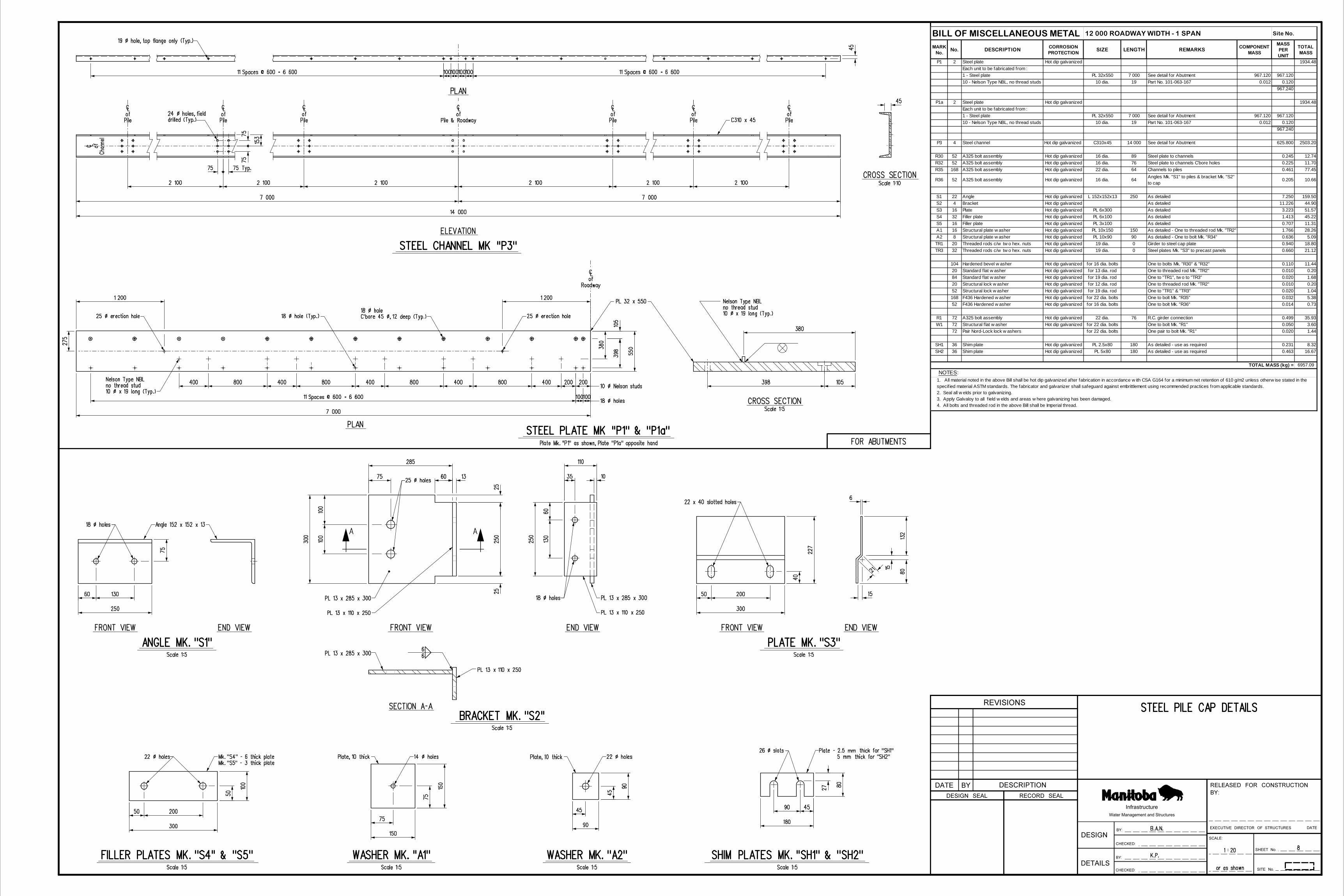
MARK No.
No. DESCRIPTIONCORROSION PROTECTION
SIZE LENGTH REMARKSCOMPONENT
MASS
MASS PER UNIT
TOTAL MASS
P1 2 Steel plate Hot dip galvanized 1934.48Each unit to be fabricated from :1 - Steel plate PL 32x550 7 000 See detail for Abutment 967.120 967.12010 - Nelson Type NBL, no thread studs 10 dia. 19 Part No. 101-063-167 0.012 0.120
967.240
P1a 2 Steel plate Hot dip galvanized 1934.48Each unit to be fabricated from :1 - Steel plate PL 32x550 7 000 See detail for Abutment 967.120 967.12010 - Nelson Type NBL, no thread studs 10 dia. 19 Part No. 101-063-167 0.012 0.120
967.240
P3 4 Steel channel Hot dip galvanized C310x45 14 000 See detail for Abutment 625.800 2503.20
R30 52 A325 bolt assembly Hot dip galvanized 16 dia. 89 Steel plate to channels 0.245 12.74R32 52 A325 bolt assembly Hot dip galvanized 16 dia. 76 Steel plate to channels C'bore holes 0.225 11.70R35 168 A325 bolt assembly Hot dip galvanized 22 dia. 64 Channels to piles 0.461 77.45
R36 52 A325 bolt assembly Hot dip galvanized 16 dia. 64 Angles Mk. "S1" to piles & bracket Mk. "S2" to cap
0.205 10.66
S1 22 Angle Hot dip galvanized L 152x152x13 250 As detailed 7.250 159.50S2 4 Bracket Hot dip galvanized As detailed 11.226 44.90S3 16 Plate Hot dip galvanized PL 6x300 As detailed 3.223 51.57S4 32 Filler plate Hot dip galvanized PL 6x100 As detailed 1.413 45.22S5 16 Filler plate Hot dip galvanized PL 3x100 As detailed 0.707 11.31A1 16 Structural plate w asher Hot dip galvanized PL 10x150 150 As detailed - One to threaded rod Mk. "TR2" 1.766 28.26A2 8 Structural plate w asher Hot dip galvanized PL 10x90 90 As detailed - One to bolt Mk. "R34" 0.636 5.09TR1 20 Threaded rods c/w tw o hex. nuts Hot dip galvanized 19 dia. 0 Girder to steel cap plate 0.940 18.80TR3 32 Threaded rods c/w tw o hex. nuts Hot dip galvanized 19 dia. 0 Steel plates Mk. "S3" to precast panels 0.660 21.12
104 Hardened bevel w asher Hot dip galvanized for 16 dia. bolts One to bolts Mk. "R30" & "R32" 0.110 11.4420 Standard f lat w asher Hot dip galvanized for 13 dia. rod One to threaded rod Mk. "TR2" 0.010 0.2084 Standard f lat w asher Hot dip galvanized for 19 dia. rod One to "TR1", tw o to "TR3" 0.020 1.6820 Structural lock w asher Hot dip galvanized for 12 dia. rod One to threaded rod Mk. "TR2" 0.010 0.2052 Structural lock w asher Hot dip galvanized for 19 dia. rod One to "TR1" & "TR3" 0.020 1.04168 F436 Hardened w asher Hot dip galvanized for 22 dia. bolts One to bolt Mk. "R35" 0.032 5.3852 F436 Hardened w asher Hot dip galvanized for 16 dia. bolts One to bolt Mk. "R36" 0.014 0.73
R1 72 A325 bolt assembly Hot dip galvanized 22 dia. 76 R.C. girder connection 0.499 35.93W1 72 Structural f lat w asher Hot dip galvanized for 22 dia. bolts One to bolt Mk. "R1" 0.050 3.60
72 Pair Nord-Lock lock w ashers for 22 dia. bolts One pair to bolt Mk. "R1" 0.020 1.44
SH1 36 Shim plate Hot dip galvanized PL 2.5x80 180 As detailed - use as required 0.231 8.32SH2 36 Shim plate Hot dip galvanized PL 5x80 180 As detailed - use as required 0.463 16.67
6957.09
1. All material noted in the above Bill shall be hot dip galvanized after fabrication in accordance w ith CSA G164 for a minimum net retention of 610 g/m2 unless otherw ise stated in the specif ied material ASTM standards. The fabricator and galvanizer shall safeguard against embrittlement using recommended practices from applicable standards. 2. Seal all w elds prior to galvanizing. 3. Apply Galvaloy to all f ield w elds and areas w here galvanizing has been damaged. 4. All bolts and threaded rod in the above Bill shall be Imperial thread.
BILL OF MISCELLANEOUS METAL
TOTAL MASS (kg) = NOTES:
Site No.12 000 ROADWAY WIDTH - 1 SPAN

MARK No.
No. DESCRIPTIONCORROSION
PROTECTIONSIZE LENGTH REMARKS
COMPONENT MASS
MASS PER UNIT
TOTAL MASS
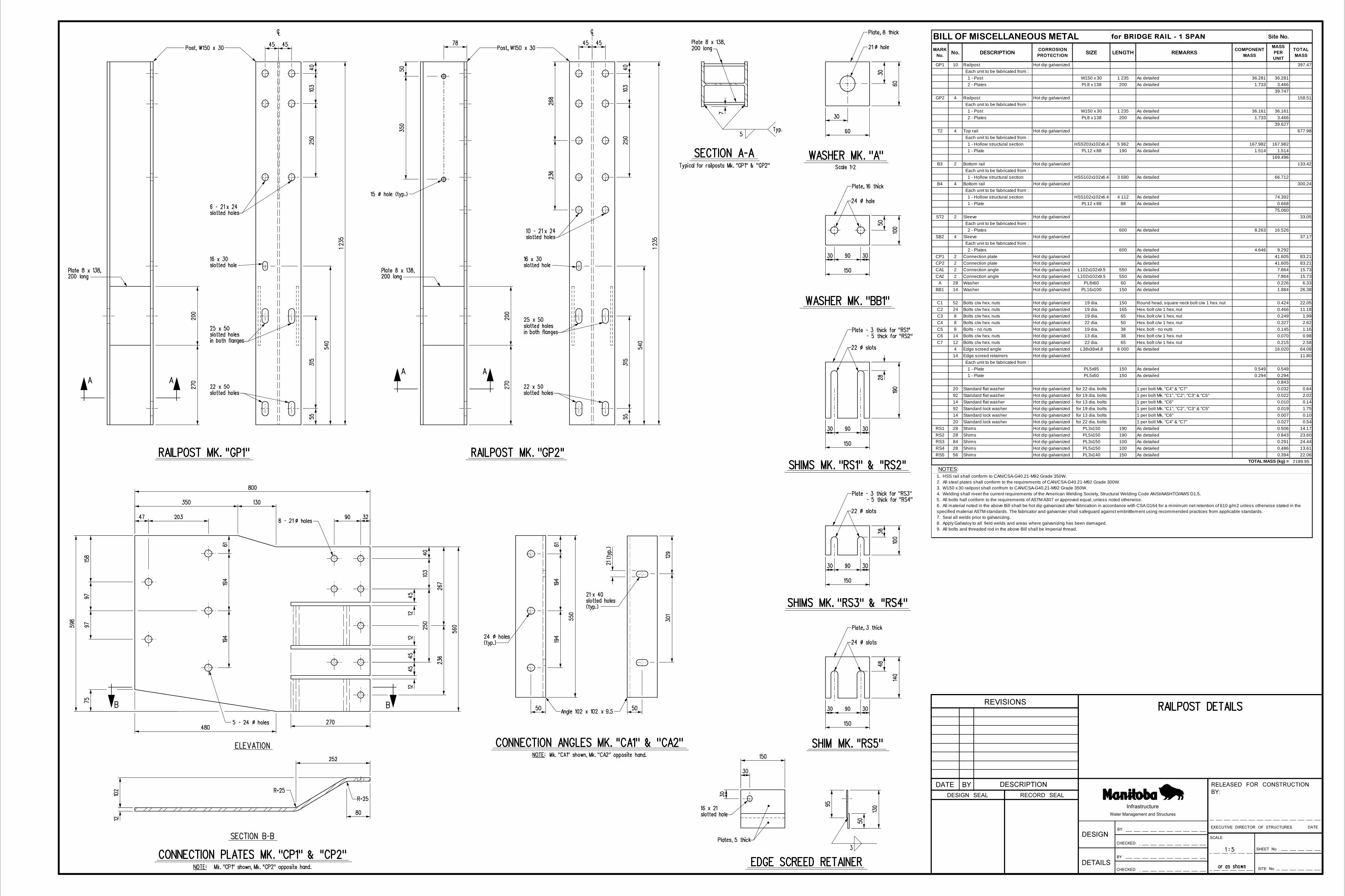
GP1 10 Railpost Hot dip galvanized 397.47 Each unit to be fabricated from : 1 - Post W150 x 30 1 235 As detailed 36.281 36.281 2 - Plates PL8 x 138 200 As detailed 1.733 3.466
39.747GP2 4 Railpost Hot dip galvanized 158.51
Each unit to be fabricated from : 1 - Post W150 x 30 1 235 As detailed 36.161 36.161 2 - Plates PL8 x 138 200 As detailed 1.733 3.466
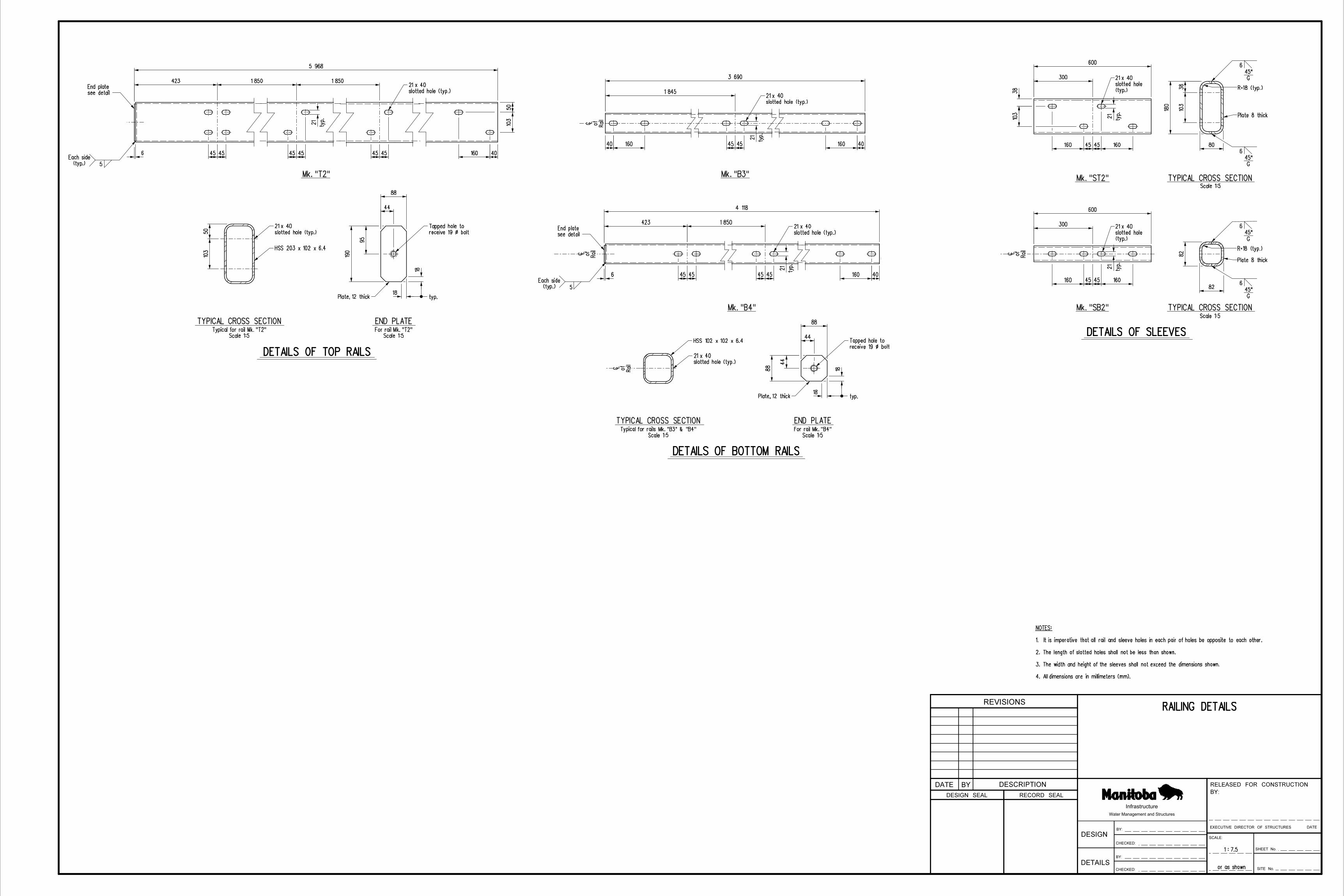
39.627T2 4 Top rail Hot dip galvanized 677.98
Each unit to be fabricated from : 1 - Hollow structural section HSS203x102x6.4 5 962 As detailed 167.982 167.982 1 - Plate PL12 x 88 190 As detailed 1.514 1.514
169.496B3 2 Bottom rail Hot dip galvanized 133.42
Each unit to be fabricated from : 1 - Hollow structural section HSS102x102x6.4 3 690 As detailed 66.712
B4 4 Bottom rail Hot dip galvanized 300.24 Each unit to be fabricated from : 1 - Hollow structural section HSS102x102x6.4 4 112 As detailed 74.392 1 - Plate PL12 x 88 88 As detailed 0.668
75.060ST2 2 Sleeve Hot dip galvanized 33.05
Each unit to be fabricated from : 2 - Plates 600 As detailed 8.263 16.526
SB2 4 Sleeve Hot dip galvanized 37.17 Each unit to be fabricated from : 2 - Plates 600 As detailed 4.646 9.292
CP1 2 Connection plate Hot dip galvanized As detailed 41.605 83.21CP2 2 Connection plate Hot dip galvanized As detailed 41.605 83.21CA1 2 Connection angle Hot dip galvanized L102x102x9.5 550 As detailed 7.864 15.73CA2 2 Connection angle Hot dip galvanized L102x102x9.5 550 As detailed 7.864 15.73
A 28 Washer Hot dip galvanized PL8x60 60 As detailed 0.226 6.33BB1 14 Washer Hot dip galvanized PL16x100 150 As detailed 1.884 26.38
C1 52 Bolts c/w hex. nuts Hot dip galvanized 19 dia. 150 Round head, square neck bolt c/w 1 hex. nut 0.424 22.05C2 24 Bolts c/w hex. nuts Hot dip galvanized 19 dia. 165 Hex. bolt c/w 1 hex. nut 0.466 11.18C3 8 Bolts c/w hex. nuts Hot dip galvanized 19 dia. 65 Hex. bolt c/w 1 hex. nut 0.249 1.99C4 8 Bolts c/w hex. nuts Hot dip galvanized 22 dia. 50 Hex. bolt c/w 1 hex. nut 0.327 2.62C5 8 Bolts - no nuts Hot dip galvanized 19 dia. 38 Hex. bolt - no nuts 0.145 1.16C6 14 Bolts c/w hex. nuts Hot dip galvanized 13 dia. 38 Hex. bolt c/w 1 hex. nut 0.070 0.98C7 12 Bolts c/w hex. nuts Hot dip galvanized 22 dia. 65 Hex. bolt c/w 1 hex. nut 0.215 2.58
4 Edge screed angle Hot dip galvanized L38x38x4.8 6 000 As detailed 16.020 64.0814 Edge screed retainers Hot dip galvanized 11.80
Each unit to be fabricated from : 1 - Plate PL5x95 150 As detailed 0.549 0.549 1 - Plate PL5x50 150 As detailed 0.294 0.294
0.84320 Standard flat washer Hot dip galvanized for 22 dia. bolts 1 per bolt Mk. "C4" & "C7" 0.032 0.6492 Standard flat washer Hot dip galvanized for 19 dia. bolts 1 per bolt Mk. "C1", "C2", "C3" & "C5" 0.022 2.0214 Standard flat washer Hot dip galvanized for 13 dia. bolts 1 per bolt Mk. "C6" 0.010 0.1492 Standard lock washer Hot dip galvanized for 19 dia. bolts 1 per bolt Mk. "C1", "C2", "C3" & "C5" 0.019 1.7514 Standard lock washer Hot dip galvanized for 13 dia. bolts 1 per bolt Mk. "C6" 0.007 0.1020 Standard lock washer Hot dip galvanized for 22 dia. bolts 1 per bolt Mk. "C4" & "C7" 0.027 0.54
RS1 28 Shims Hot dip galvanized PL3x150 190 As detailed 0.506 14.17RS2 28 Shims Hot dip galvanized PL5x150 190 As detailed 0.843 23.60RS3 84 Shims Hot dip galvanized PL3x150 100 As detailed 0.291 24.44RS4 28 Shims Hot dip galvanized PL5x150 100 As detailed 0.486 13.61RS5 56 Shims Hot dip galvanized PL3x140 150 As detailed 0.394 22.06
2189.95TOTAL MASS (kg) =
NOTES:1. HSS rail shall conform to CAN/CSA-G40.21-M92 Grade 350W.2. All steel plates shall conform to the requirements of CAN/CSA-G40.21-M92 Grade 300W.3. W150 x 30 railpost shall confrom to CAN/CSA-G40.21-M92 Grade 350W.4. Welding shall meet the current requirements of the American Welding Society, Structural Welding Code ANSI/AASHTO/AWS D1.5.5. All bolts hall conform to the requirements of ASTM A307 or approved equal, unless noted otherwise.6. All material noted in the above Bill shall be hot dip galvanized after fabrication in accordance with CSA G164 for a minimum net retention of 610 g/m2 unless otherwise stated in the specified material ASTM standards. The fabricator and galvanizer shall safeguard against embrittlement using recommended practices from applicable standards.7. Seal all welds prior to galvanizing.8. Apply Galvaloy to all field welds and areas where galvanizing has been damaged.9. All bolts and threaded rod in the above Bill shall be Imperial thread.
BILL OF MISCELLANEOUS METAL for BRIDGE RAIL - 1 SPAN Site No.

Site No.
MARK No.
No. DESCRIPTION CORROSION PROTECTION
SIZE LENGTH
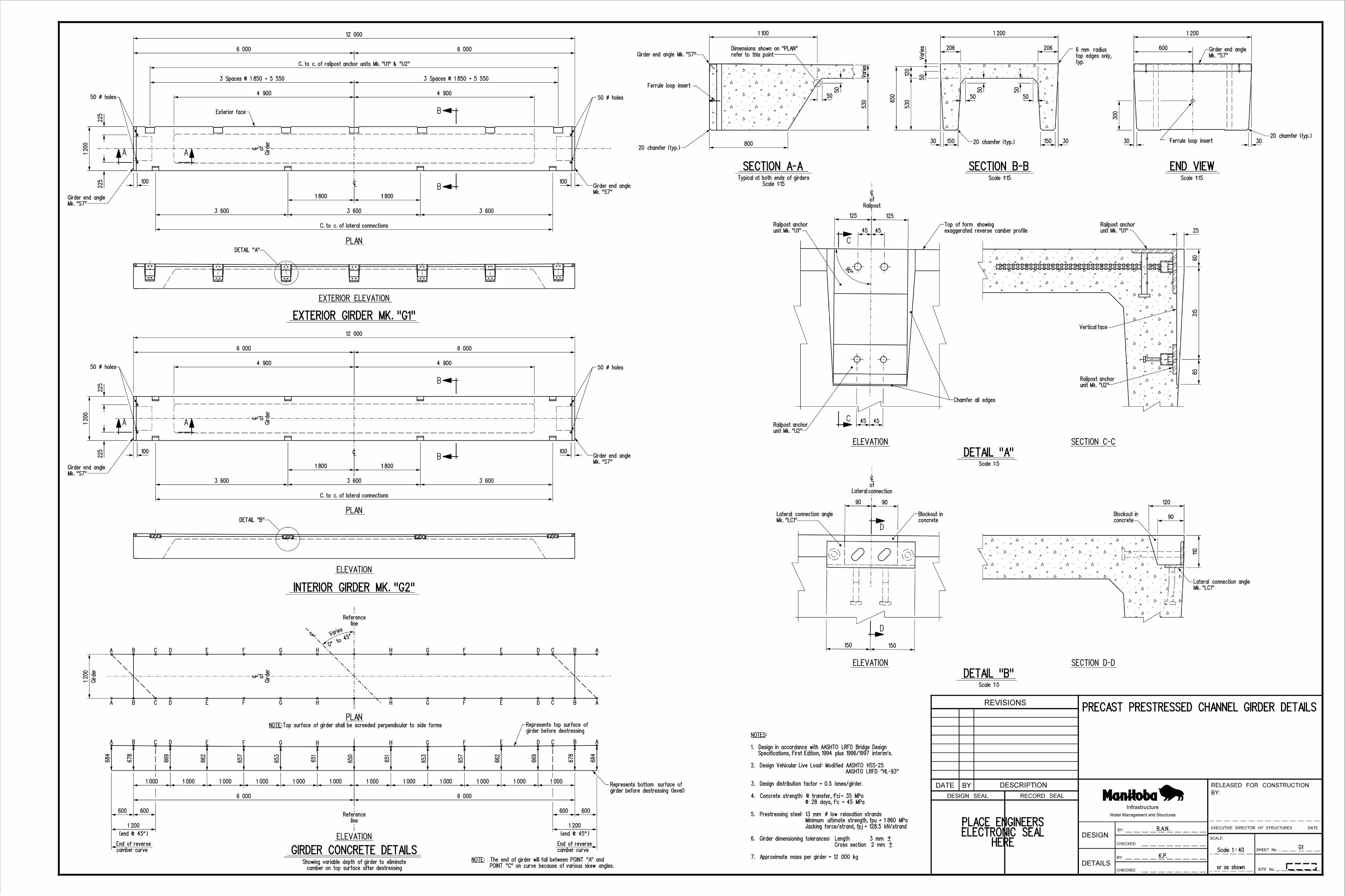
U1 14 Railpost anchor unit Hot dip galvanizedEach unit is fabricated from:
1 - Angle L152x152x13 2502 - Heavy hex. nuts for 22 dia. bolt2 - Studs 19 dia. 1503 - Bars for 19 dia. bolt 6002 - Tubes
U2 14 Railpost anchor unit Hot dip galvanizedEach unit is fabricated from:
1 - Plate PL 13x100 2502 - Heavy hex. nuts for 19 dia. bolt3 - Studs 10 dia. 1002 - Tubes
LC1 72 Lateral connection angle Hot dip galvanizedEach unit is fabricated from:
1 - Angle L89x64x9.5 3002 - Studs 19 dia. 2002 - Studs 19 dia. 125
S7 20 Girder end angle Hot dip galvanizedEach unit is fabricated from:
1 - Angle L76x76x6.4 1 1942 - Plates PL 3x75 753 - Studs 10 dia. 100
20 Ferrule loop insert Stainless steel for 13 dia. bolt
TR2 20 Threaded rod Stainless steel 13 dia. 250
R27 28 A325 bolt c/w F436 hardened w asher Hot dip galvanized 22 dia. 229R28 28 A325 bolt c/w F436 hardened w asher Hot dip galvanized 19 dia. 64
NOTES:1. All material in the above Bill shall be supplied by the GIRDER CONTRACTOR.2. All structural steel shall conform to CAN/CSA G40.21-M92 Grade 300W.3. All material noted in the above Bill shall be hot dip galvanized after fabrication in accordance w ith CSA G164 for a minimum net retention of 610 g/m2 unless otherw ise stated in the specif ied material ASTM standards. The fabricator and galvanizer shall safeguard against embrittlement using recommended practices from applicable standards.4. Seal all w elds prior to galvanizing.5. Grade DH or 2H galvanized nuts for A325 bolts shall be overtapped to a minimum amount required for the fastener assembly in accordance w ith ASTM F3125. The nuts shall be lubricated w ith a lubricant containing a visible dye. The lubricant shall be clean and dry to the touch.6. All bolts and inserts in the above Bill shall be Imperial thread.7. Stainless steel shall conform to the requirements of ASTM A320, Class B8.
Richmond anchor, Type LF-W w ith mounting w asher
c/w hex. nut
Heavy hex. no nut, ASTM F3125Heavy hex. no nut, ASTM F3125
As detailedHeaded stud anchors, ASTM A108Headed stud anchors, ASTM A108
As detailedAs detailedHeaded stud anchors, ASTM A108
Grade DH or 2HHeaded stud anchors, ASTM A108Nelson deformed bar anchors, Type D2LMetal or plastic capped - As detailed
As detailedGrade DH or 2HHeaded stud anchors, ASTM A108Metal or plastic capped - As detailed
As detailed
BILL OF MISCELLANEOUS METAL for 12 m LONG GIRDERS 12 000 ROADWAY WIDTH - 1 SPAN
REMARKS