Embed Size (px)
Citation preview

Version 4.0English
50403020
General Guide to DTM Stakeout
GPS System 500

2 General Guide to DTM Stakeout - 4.0.0en
Congratulations on your purchase of a new Leica SystemGPS500.
System GPS500

3General Guide to DTM Stakeout - 4.0.0en
View of chapters
Introduction
Preparation
Surveying a DTM
Staking a DTM
5
7
20
23
View of chapters

4 General Guide to DTM Stakeout - 4.0.0en
Contents
Contents
Introduction ................................................... 5Activation of the Application ......................................... 5Requirements .............................................................. 6
Preparation .................................................... 7DTM data format ......................................................... 7Leica GSI data format .................................................. 8
Example for a DTM file in Leica GSI8 format .................... 8Example for a DTM file in Leica GSI16 format .................. 9Header of a DTM file in Leica GSI8 format ..................... 10Data line for triangle vertex in a DTM file inLeica GSI8 format ........................................................... 11Creating a DTM file in Leica GSI8 format withLISCAD V5.0 .................................................................. 12
AutoCAD DXF data format ........................................ 13Example for a DTM file in AutoCAD DXF format ............. 13Creating a DTM file in AutoCAD DXF format withLISCAD V5.0 .................................................................. 14
Copy the DTM file to the PCMCIA card ...................... 16Transferring a DTM file directly from the PC to the card .. 16Transferring a DTM file to the card using SensorTransfer in SKI-Pro ......................................................... 17
The Coordinate System ............................................. 18Receiver set-up ......................................................... 18Setting the units ........................................................ 19
Surveying a DTM ......................................... 20Starting the application .............................................. 20
Staking a DTM.............................................. 23Configuring Stakeout to use a DTM file ...................... 23Selecting the correct DTM file .................................... 25Staking a DTM .......................................................... 27

5General Guide to DTM Stakeout - 4.0.0en
Introduction
Introduction
This manual describes the application program DTMStakeout (Digital Terrain Model) for the Leica GPSSystem 500. With DTM Stakeout you can
• navigate around an entered DTM. When in thismode, the system will display the coordinatevalues of the point being measured at that timeand the cut or fill in relation to the DTM.
• stake points anywhere within an entered DTM,store the coordinate values of the points that havebeen staked as well as the cut or fill from the pointon the actual ground suface to the DTM.
The DTM can be created in AutoCAD DXF or in LeicaGSI format by using for example LISCAD. Please refer tochapter „Preparation“ for more information.
Activation of the Application
The application is initially activated by an access codewhich is provided by Leica. If the application does notappear on your menu or you are otherwise unable toaccess the application, please contact your Leica repre-sentative.

6 General Guide to DTM Stakeout - 4.0.0en
Requirements
You must be familiar with the principles and proceduresthat are outlined in the manual „Getting Started withReal-Time Surveys“ as well as the “Technical ReferenceManual”.If the material referenced is not thoroughly understood, itis strongly advised that you review them prior to proceed-ing with this application program.Within this document, it is assumed that you are familiarwith the operation of the system.
Introduction

7 PreparationGeneral Guide to DTM Stakeout - 4.0.0en
Preparation DTM data format
Before starting the application program, the DTM must beprepared and stored on the memory card and the appro-priate coordinate system relating to the DTM must beselected.
The data for the DTM Stakeout program may be preparedin one of three formats: standard Leica GSI8, standardLeica GSI16 or AutoCAD DXF.The file may be named any valid DOS name with either.gsi (for Leica GSI format) or .dxf (for AutoCAD DXFformat) extension.

8Preparation General Guide to DTM Stakeout - 4.0.0en
Leica GSI data format
Example for a DTM file in Leica GSI8 format
Below is an example of a DTM file in Leica GSI8 format.The top half of the file shows the header and coordinatesof the first two triangle vertices. The bottom half of the fileshows the coordinate records of the last two triangles.Additionally, in the complete listing of the data file therewould also be coordinate records for the triangle verticesfor triangles from 3 to 50.
Note that each line must end with a blank andthat a CR/LF is required after the last data line.

9 PreparationGeneral Guide to DTM Stakeout - 4.0.0en
Example for a DTM file in Leica GSI16 format
Below is the same example in Leica GSI16 format.In contrast to Leica GSI8 format, each line in a GSI16 filestarts with a *. And all values (not the word indexes) have16 digits instead of 8. Values are extended to 16 digits byadding zeros from the left.Except for these differences, everything else said aboutGSI8 in the following sections also applies to GSI16, too.
Note that each line must end with a blank andthat a CR/LF is required after the last data line.

10Preparation General Guide to DTM Stakeout - 4.0.0en
Header of a DTM file in Leica GSI8 format
The header is the first line in the GSI file. There is only one header line per file.The header line takes the following form:
41….+000JOBID 42….+DTMNTWRK 43….+DTMCOORD 44….+00000000 45….+00000000
The word indexes are:
WI 41 Job identification, maximum 8 characters, may be defined by user.
WI 42 Identification of DTM file, may not be changed by user. This entry must be +DTMNTWRK.
WI 43 Identification of principal point type, may not be changed by user. This entry must be +DTMCOORD.
WI 44 Optional easting offset. May be defined by user.
WI 45 Optional northing offset. May be defined by user.
Note that the values for easting and northing offset have no digits to the right of the decimal place. Forexample, +001000000 means that 1000000 will be added to the coordinates of the triangle vertices.

11 PreparationGeneral Guide to DTM Stakeout - 4.0.0en
Data line for triangle vertex in a DTM file in Leica GSI8 format
In a DTM GSI file, the data line records for the triangle vertices follow the header line. One line describes one vertexof one triangle by its coordinates. One triangle is fully described by three lines - one for each vertex.The coordinates should be sorted by triangles. It is therefore obvious that three coordinate lines with the sametriangle number should be found together in the file. There is however no need to sort the vertices itself for onetriangle.
A data line for one triangle vertex is shown below:
110002+00000002 71….+TRI00001 81..11+05000000 82..11+01080263 83..11+00109688
The word indexes are:
11IW .noitacilppaehtybderongi,noitacifitneditnioP
17IW .sgnolebetanidroocehtelgnairthcihwotsetacidni,rebmunelgnairT
18IW .xetrevelgnairtehtfognitsaE
28IW .xetrevelgnairtehtfognihtroN
38IW .xetrevelgnairtehtfonoitavelE

12Preparation General Guide to DTM Stakeout - 4.0.0en
Creating a DTM file in Leica GSI8 format with LISCAD V5.0
It is assumed that LISCAD Plus S.E.E. is running with thedrawing file (*.see) open and a Digital Terrain Model hasalready been created for this file.
�From the menu bar select Task, Field Transfer.�Also from the menu bar select Output, Data Recorder.�A dialogue called Data Recorder Output appears.Click the Install ... button. This leads to a new dialogueInstall Data Recorder Devices.�In the box Supported Devices either highlight LeicaTPS - 1100 Series or Leica TPS - 1000 Series and clickAdd.... The selected instrument will appear in the boxInstalled Devices. Click Close.
�In the dialogue Data Recorder Output tick DigitalTerrain Model. Click OK.
�In the new window Output Digital Terrain Modeltick the option Output to file. Click OK.�The next screen gives all necessary input optionsfor Save As. Select a directory and a file name. Notethat the file requires the extension .gsi. Even though theSave as type box only shows the option text file (*.txt), it ispossible to type the file name plus the .gsi extension inthe box File name. Click Save.

13 PreparationGeneral Guide to DTM Stakeout - 4.0.0en
AutoCAD DXF data format
Example for a DTM file in AutoCAD DXF format
DTM triangles are imported to DTM Stakeout as 3DFACEentities from a DXF file. The format is as follows:
Properties, Layers, etc. may be in the DXF file, but areignored by the DTM Stakeout application. The completionof the polygon by repeating the first point is required byAutoCAD, but is not required by the DTM Stakeoutapplication. There will be a record like the one outlinedabove for each triangle in the DXF file.

14Preparation General Guide to DTM Stakeout - 4.0.0en
Creating a DTM file in AutoCAD DXF format with LISCAD V5.0
It is assumed that LISCAD Plus S.E.E. is running with thedrawing file (*.see) open and a Digital Terrain Model hasalready been created for this file.
�From the menu bar select Task, Terrain Modelling.�Then also on the menu bar, go to Display, Features….�In the dialogue Feature Display select the tab viewModel. Ensure Triangles is checked and Triangle num-bers and Contours is not checked. Click OK.
�On the menu bar, go to Display, Groups… Turn off allGroups but DEFAULT. Click OK.
�From the menu bar select Task, CAD Output.�Under Settings, CAD System tick AutoCAD DXF.
�Go to Settings, Codes… next. Only in the tab viewGeneral turn off all options .

15 PreparationGeneral Guide to DTM Stakeout - 4.0.0en
�Under Settings, Model… set Labels to none andcheck the Triangles check box.
�Click Output! on the menu bar to access the AutoCADDXF dialogue.�Click the Options button. A new dialogue Optionsappears.�On the tab view General tick Model and Use Defaultfor All. Untick all other option check boxes.
�In the same dialogue on the tab view AutoCAD tick 3Dimensional. Click OK.
�Back in the dialogue AUTOCAD DXF for Save as type:select AutoCAD (*.dxf), define a file name and select adirectory for storing the file. Clicking OK creates the DXFfile.
You may also create a CAD Output ParameterFile of these settings which will make thecreation of DXF files easier for further outputs.Refer to LISCAD on-line help on how to createa CAD Output Parameter File.

16Preparation General Guide to DTM Stakeout - 4.0.0en
Copy the DTM file to the PCMCIA card Transferring a DTM file directly from the PC to the card
Once the DTM file has been created, it needs to becopied to the PCMCIA card.If your computer has a PC card reader, you can transferthe data files directly from the PC to the card. Use thesensor transfer option in SKI-Pro if no PC card reader isavailable on the PC being used.
�Format the PCMCIA card in the sensor.�Insert the card into the PC.�By using the Explorer, copy the data files from the harddrive of the PC into the directory GSI on the memory card.

17 PreparationGeneral Guide to DTM Stakeout - 4.0.0en
Transferring a DTM file to the card using Sensor Transfer in SKI-Pro
�Switch the Sensor off.�Remove the TR500 terminal from the sensor.�Connect the data transfer cable to the serial port ofyour computer and to the TERMINAL port on the Sensor.�Start SKI-Pro. Go to Sensor Transfer under Tools.�Right-click on Sensor, go to Settings... and checkthe serial port and the baud rate settings.�Right-click on Sensor and choose Turn GPS Sensoron.�Right-click on Sensor and select Transfer Any File.
�Under Look in: select the directory where your GSI orDXF file is kept.�Under Files of Type: select GSI or DXF depending onthe file you wish to transfer.�Under Sensor device: select PC-card.�Under Directory: select DTM.�Highlight the file to be transferred and click the Transferbutton.�Once the transfer is finished, right-click on Sensorand choose Turn GPS Sensor off.

18Preparation General Guide to DTM Stakeout - 4.0.0en
The Coordinate System Receiver set-up
In order to get the correct result when surveying orstaking out with a DTM, the GPS jobs must be orientatedto the same local grid coordinate system as the DTM.This is accomplished by attaching an appropriate coordi-nate system to the job consisting of the three compo-nents transformation, ellipsoid and projection.
Depending on the coordinate system, you will either usepre-defined parameters or determine the required trans-formation parameters either on the sensor or in SKI-Pro.
On how to set up a coordinate system and on how tocalculate transformation parameters please refer to„Getting Started with Real-Time Surveys“ as well as the"Technical Reference Manual" for assistance.
DTM Stakeout is a real-time application.
Therefore, a properly initialised real-time configurationset is required. This means, reference and rover must beset-up properly running a suitable configuration set andthe data transfer from the reference to the rover must beworking.
For detailed information please refer to „Getting Startedwith Real-Time Surveys“ and the "Technical ReferenceManual".

19 PreparationGeneral Guide to DTM Stakeout - 4.0.0en
Setting the units
The GPS sensors must be configured in the samecoordinate units as those of the generated DTM.
Check the sensor settings in panel CONFIGURE \ Units.
The units must not be changed while surveying the DTM.

20Surveying a DTM General Guide to DTM Stakeout - 4.0.0en
Surveying a DTM
This section explains who to use the DTM application toverify an existing surface with a design surface.
Starting the application
Switch the receiver ON > Main MenuSelect 3 Applications ...CONT (F1)
Remember to ensure that the icon for the accuracy statusshows the symbol for high precision navigation.
Panel APPLICATION \ Menu08 DTM StakeoutCONT (F1)
21 Surveying a DTMGeneral Guide to DTM Stakeout - 4.0.0en
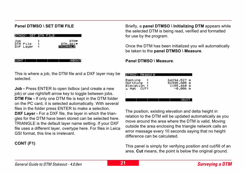
Panel DTMSO \ SET DTM FILE
This is where a job, the DTM file and a DXF layer may beselected.
Job - Press ENTER to open listbox (and create a newjob) or use right/left arrow key to toggle between jobs.DTM File - If only one DTM file is kept in the DTM folderon the PC card, it is selected automatically. With severalfiles in the folder press ENTER to make a selection.DXF Layer - For a DXF file, the layer in which the trian-gles for the DTM have been stored can be selected here.TRIANGLE is the default layer name setting. If your DXFfile uses a different layer, overtype here. For files in LeicaGSI format, this line is irrelevant.
CONT (F1)
Briefly, a panel DTMSO \ Initializing DTM appears whilethe selected DTM is being read, verified and formattedfor use by the program.
Once the DTM has been initialized you will automaticallybe taken to the panel DTMSO \ Measure.
Panel DTMSO \ Measure.
The position, existing elevation and delta height inrelation to the DTM will be updated automatically as youmove around the area where the DTM is valid. Movingoutside the area enclosing the triangle network calls anerror message every 10 seconds saying that no heightdifference can be calculated.
This panel is simply for verifying position and cut/fill of anarea. Cut means, the point is below the original ground.

22Surveying a DTM General Guide to DTM Stakeout - 4.0.0en
Fill means, the point is above the original ground.
There is no further need for action in this panel.For staking a DTM and saving staked points proceed tothe next chapter.

23 Staking a DTMGeneral Guide to DTM Stakeout - 4.0.0en
Staking a DTMThe following section of this guide explains how to usethe DTM application to stakeout points in relation to aDTM which is the design surface.
Before starting staking a DTM, make sure that all instruc-tions mentioned in the chapter "Preparations" are readand carried out.
Prior to staking out, the coordinates of the points to bestaked need to be transferred from an ASCII file on thePC card in the subdirectory \ Data to a job on the sensor.For this, use 7 TRANSFER from the main menu and then06 ASCII/GSI to Job (see also the "Technical ReferenceManual").
Configuring Stakeout to use a DTM file
Normally, the Stakeout application on the System 500compares the height actual being measured with the oneto be staked and gives cut or fill values relative to thepoint being staked.
With the DTM Stakeout option however, the normalStakeout application can use a DTM as the height datumand will show cut and fill values relative to the DTM.
Since it is possible that a user may sometimes wish touse the DTM model and sometimes stake points, theoption whether or not to use a DTM with the Stakeoutapplication is user configurable.The procedure required is as follows:
Switch ON > Main MenuPress the CONFIG key.Panel CONFIGURE \ Rt_rov.cnf (where Rt_rov.cnf isthe name of the currently active configuration set).

24Staking a DTM General Guide to DTM Stakeout - 4.0.0en
1 SurveyCONT (F1)
Panel CONFIGURE \ Survey
4 Stake-OutCONT (F1)
Panel CONFIGURE \ Stake-OutUse the up/down arrow key to highlight the line UseDTM. Initially, on entering the panle this line is invisibleuntil you scroll down twice after the line Diff Check.
Use the right/left arrow key to toggle to YES.
CONT (F1) returns to the main menu.

25 Staking a DTMGeneral Guide to DTM Stakeout - 4.0.0en
Selecting the correct DTM file
In the main menu screen select 2 Stake-Out ....CONT (F1)
Remember to ensure that the icon for the accuracy statusshows the symbol for high precision navigation.
Panel STAKE-OUT \ Begin
Config Set - Select a real-time rover configuration, e.g.Rt_rov.Stake Pts - The job where the points to be staked arekept. Select the job.Store Pts - The job where the staked points will bestored. Either select an existing job from the listbox orpress NEW (F2) to create a new job.Stake Type - Select Point.Antenna - Select your antenna setup, e.g. AT502 Pole.Ant Height - Enter the antenna height, when using theLeica standard pole setup it is 2.000 m.
Once all information is entered:DTM (F5)
Panel DTMSO \ SET DTM FILE
You now have to select a job, the DTM file and a DXFlayer.

26Staking a DTM General Guide to DTM Stakeout - 4.0.0en
Job - Press ENTER to open listbox (and create a newjob) or use right/left arrow key to toggle between jobs.DTM File - If only one DTM file is kept in the DTM folderon the PC card, it is selected automatically. With severalfiles in the folder press ENTER to make a selection.DXF Layer - For a DXF file, the layer in which the trian-gles for the DTM have been stored can be selected here.TRIANGLE is the default layer name setting. If your DXFfile uses a different layer, overtype here. For files in LeicaGSI format, this line is irrelevant.
CONT (F1)
Briefly, a panel DTMSO \ Initializing DTM appears whilethe selected DTM is being read, verified and formattedfor use by the program.
Once the DTM has been initialized you will automaticallybe taken to the panel DTMSO \ Measure.
Panel DTMSO \ Measure.
This panel is simply for verifying position and cut/fill ofan area. Cut means, the point is below the originalground. Fill means, the point is above the originalground. There is no further need for action in this panel.
The values for position, existing elevation and deltaheight in relation to the DTM are updated automaticallyas you move around the area where the DTM is valid.Moving outside the area enclosing the triangle networkcalls an error message saying that height differencescannot be calculated.
For staking a DTM and saving staked points press QUIT(F6) to return to the STAKEOUT \ Begin screen.
27 Staking a DTMGeneral Guide to DTM Stakeout - 4.0.0en
Staking a DTM
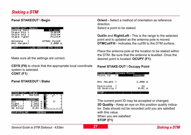
Panel STAKEOUT \ Begin
Make sure all the settings are correct.
CSYS (F6) to check that the appropriate local coordinatesystem is selected.CONT (F1)
Panel STAKEOUT \ Stake
Orient - Select a method of orientation as referencedirection.Select a point to be staked.
Out/In and Right/Left - This is the range to the selectedpoint and is updated as the antenna pole is moved.DTMCut/Fill - Indicates the cut/fill to the DTM surface.
Place the antenna pole at the location to be staked withinthe DTM. Be sure that the antenna is levelled. Once thedesired point is located: OCUPY (F1).
Panel STAKE-OUT \ Occupy Point
The current point ID may be accepted or changed.3D Quality - Keep an eye on this position quality indica-tor. Data should not be recorded until you are satisfiedwith this value.When you are satisfied:STOP (F1)

28Staking a DTM General Guide to DTM Stakeout - 4.0.0en
When surveying outside of the area enclosing the trianglenetwork, no height can be calculated. A warning will thenappear every 10 seconds.
DIFF (F2)
Pressing this key gives the difference between thedesigned coordinates and staked coordinates of thepoint.
STORE (F1)
The system returns to panel STAKEOUT \ Stake and thenext point to be staked can be selected.No heights can be calculated for points lying outside ofthe area enclosing the triangle network. A warning willappear when storing such points.
For complete information on how to use STAKE-OUTplease refer to chapter "Real-Time Rover, Staking Out" inthe "Technical Reference Manual".

Leica Geosystems AG, Heerbrugg,Switzerland, has been certified as beingequipped with a quality system whichmeets the International Standards ofQuality Management and QualitySystems (ISO standard 9001) and Envi-ronmental Management Systems (ISOstandard 14001).
Total Quality Management-Our commitment to total customersatisfaction
Ask your local Leica agent for moreinformation about our TQM program
Leica Geosystems AGCH-9435 Heerbrugg
(Switzerland)Phone +41 71 727 31 31
Fax +41 71 727 46 73www.leica-geosystems.com
Printed in Switzerland - Copyright LeicaGeosystems AG, Heerbrugg, Switzerland 2002Original text
725973 - 4.0.0en


![Overview and Scutiny Power BI slides.pptx [Read-Only]€¦ · Dtm 4 Consultant Pod g Dtm I Dtm 8 7 Dtm 3 8 7 Dtm 6 Dtm Pod 4 8 Dtm Pod 4 5 Dtm 2 8 Dtm Pod 8 Dtm I 7 Dtm 4 Dtm Pod](https://img.pdfslide.net/doc/110x75/5fb41d34b5c9a8274925974c/overview-and-scutiny-power-bi-read-only-dtm-4-consultant-pod-g-dtm-i-dtm-8-7-dtm.jpg)