Embed Size (px)
Citation preview
Version 4.10English
50403020
General Guide to RoadPlus
GPS System 500
2 General Guide to RoadPlus - 4.1.0en
Congratulations on your purchase of a new Leica SystemGPS500.
System GPS500
3General Guide to RoadPlus - 4.1.0en
View of chapters
Introduction
Design Elements
Data Files and Formats
Terminology of Road Staking
Staking a Road Alignment
Glossary
Index
6
8
22
44
48
69
74
View of chapters

4 General Guide to RoadPlus - 4.1.0en
Contents
Contents
Introduction ................................................... 6Activation of the Application ......................................... 6Requirements .............................................................. 7
Design Elements ........................................... 8The Horizontal Alignment ............................................. 9The Vertical Alignment ............................................... 12The Cross Section ..................................................... 15The Cross Section Assignment .................................. 17The Station Equation ................................................. 20
Data Files and Formats ............................... 22The Horizontal Alignment File .................................... 23
Example for a Horizontal Alignment File inLeica GSI format ............................................................. 23Header of a Horizontal Alignment File inLeica GSI format ............................................................. 24Data line for a principle point in a Horizontal AlignmentFile in Leica GSI format .................................................. 25
The Vertical Alignment File......................................... 27Example for a Vertical Alignment File inLeica GSI format ............................................................. 27Header of a Vertical Alignment File in Leica GSI format .. 28Data line for a principle point in a Vertical Alignment Filein Leica GSI format ......................................................... 29
The Cross Section (Template) File ............................. 31Example for a Cross Section File in Leica GSI format ..... 31Header of a Cross Section File in Leica GSI format ........ 32
Data line for a vertex in a Cross Section File inLeica GSI format ............................................................. 33
The Cross Section Assignment File ........................... 35Example for a Cross Section Assignment File inLeica GSI format ............................................................. 35Header of a Cross Section Assignment File inLeica GSI format ............................................................. 36Data line in a Cross Section Assignment File inLeica GSI format ............................................................. 37
The Station Equation File ........................................... 38Example for a Station Equation File in Leica GSI format . 38Header of a Station Equation in Leica GSI format ........... 39Data line in a Station Equation File in Leica GSI format .. 40
Creating RoadPlus project files .................................. 41Copy the data files to the PCMCIA card ...................... 42
Transferring the data files directly from thePC to the card ................................................................ 42Transferring the data files to the card usingSensor Transfer in SKI-Pro ............................................. 43
Terminology of Road Staking ..................... 44The Cut ..................................................................... 45The Fill ...................................................................... 46The Technical Terms ................................................. 47

5General Guide to RoadPlus - 4.1.0en Contents
Staking a Road Alignment .......................... 48The Coordinate System ............................................. 48Receiver set-up ......................................................... 49Setting the units ......................................................... 49Starting the Application .............................................. 50Configuring Road Stakeout Parameters ..................... 50Selecting the Files ..................................................... 52Staking even stations of the Horizontal Alignment ....... 53Staking uneven stations of the Horizontal Alignment ... 56Staking a Cross Section ............................................. 59Staking a Catch Point ................................................ 63
Glossary ....................................................... 69
Index ............................................................. 74

6 General Guide to RoadPlus - 4.1.0en
Introduction
Introduction
This manual is an introduction to the application programRoadPlus for the Leica GPS Sytem 500. RoadPlus is acomplete road package application primarily intended forstaking out of roads. Furthermore, it is also applicable torailways, canals, damns, pipelines or any other project that isdefinable as curvilinear alignments with optional crosssectional information.The program supports
� the staking out of individual points using horizontal andvertical alignments and cross sections.
� station equations.� cross section assignment by station cross section
definition.� cross section.� interpolation superelevation.� widening.� staking out of catch points.
Activation of the Application
The application is activated by an access code which isprovided by Leica. If the application does not appear on yourmenu or you are otherwise unable to access it, please contactyour Leica representative.
7General Guide to RoadPlus - 4.1.0en
Requirements
You must be familiar with the principles and procedures thatare outlined in the manual �Getting Started with Real-TimeSurveys� as well as the �Technical Reference Manual�.If the material referenced is not thoroughly understood, it isstrongly adviced that you review them prior to proceeding withthis application program.Within this manual, it is assumed that you are familiar with theoperation of the system.
Introduction
8Design Elements General Guide to RoadPlus - 4.1.0en
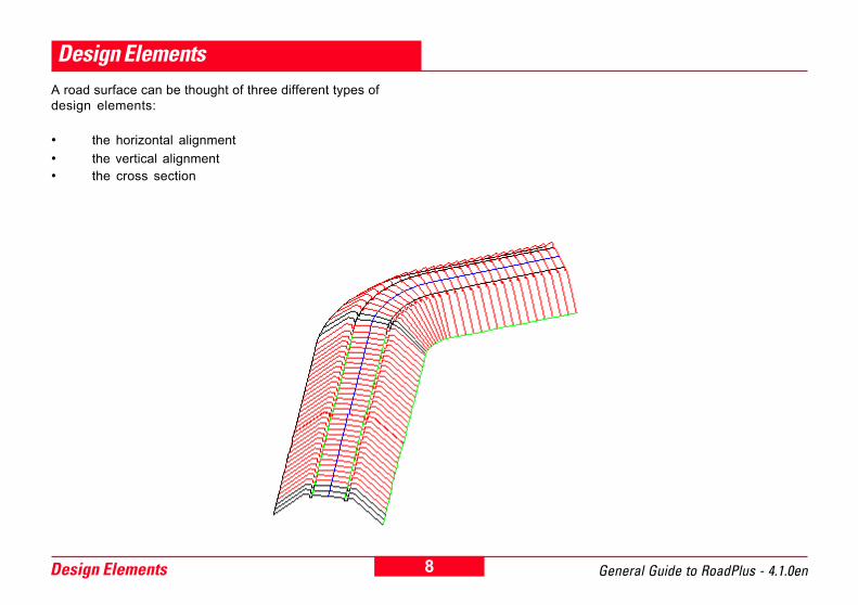
Design ElementsA road surface can be thought of three different types ofdesign elements:
� the horizontal alignment� the vertical alignment� the cross section
9 Design ElementsGeneral Guide to RoadPlus - 4.1.0en
The Horizontal Alignment
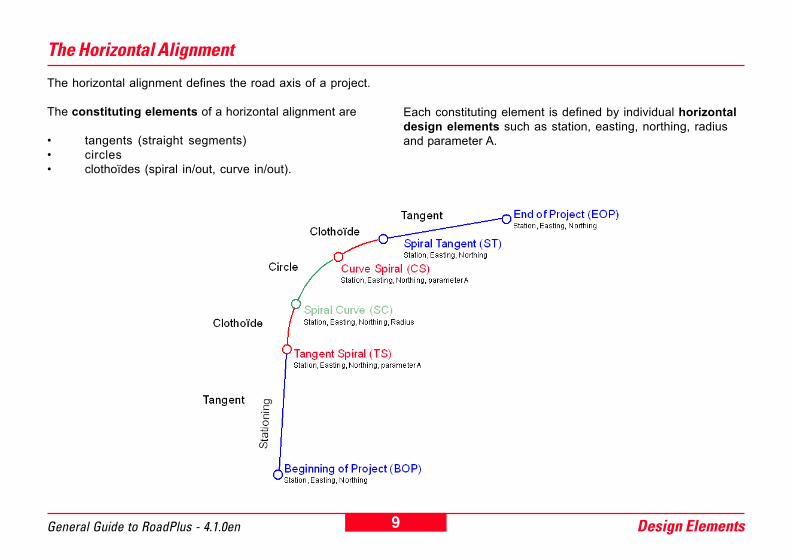
The horizontal alignment defines the road axis of a project.
The constituting elements of a horizontal alignment are
� tangents (straight segments)� circles� clothoïdes (spiral in/out, curve in/out).
Each constituting element is defined by individual horizontaldesign elements such as station, easting, northing, radiusand parameter A.

10Design Elements General Guide to RoadPlus - 4.1.0en
For the reason of completness, a short summary of thedesign elements for horizontal alignment is included in thischapter.
The Tangent - straight line between two points. It's end pointis identical with the beginning of a curve or spiral. The tangentis perpendicular to the radius of the curve.
Sipral in - spiral transition from tangent to curve.

11 Design ElementsGeneral Guide to RoadPlus - 4.1.0en
station E1, N1station E2, N2
station E1, N1
station E2, N2
A2 = R x L
Curve in - spiral transition from larger to smaller radius curve.
Curve out - spiral transition from smaller to larger radiuscurve.
Curve in and out are used for combinations such as:
curve - curve in - curve out - curveortangent - spiral in - curve in - curve
whereas spiral in/out always connect a tangent with a curve /curve in / curve out.
Parameter A
R radius of the connecting circular curveL length of the spiral in/out or curve in/out
Sign convention for curves and spirals:
centre of curvature to left of centre line: R resp. A < 0centre of curvature to right of centre line: R resp. A > 0
Or in words: Looking in the direction of increasing station,apply the "right hand positive rule".
12Design Elements General Guide to RoadPlus - 4.1.0en
The Vertical Alignment
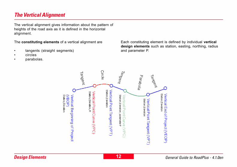
The vertical alignment gives information about the pattern ofheights of the road axis as it is defined in the horizontalalignment.
The constituting elements of a vertical alignment are
� tangents (straight segments)� circles� parabolas.
Each constituting element is defined by individual verticaldesign elements such as station, easting, northing, radiusand parameter P.
13 Design ElementsGeneral Guide to RoadPlus - 4.1.0en
station Z1
station Z2
station Z1 station Z2
parameter P
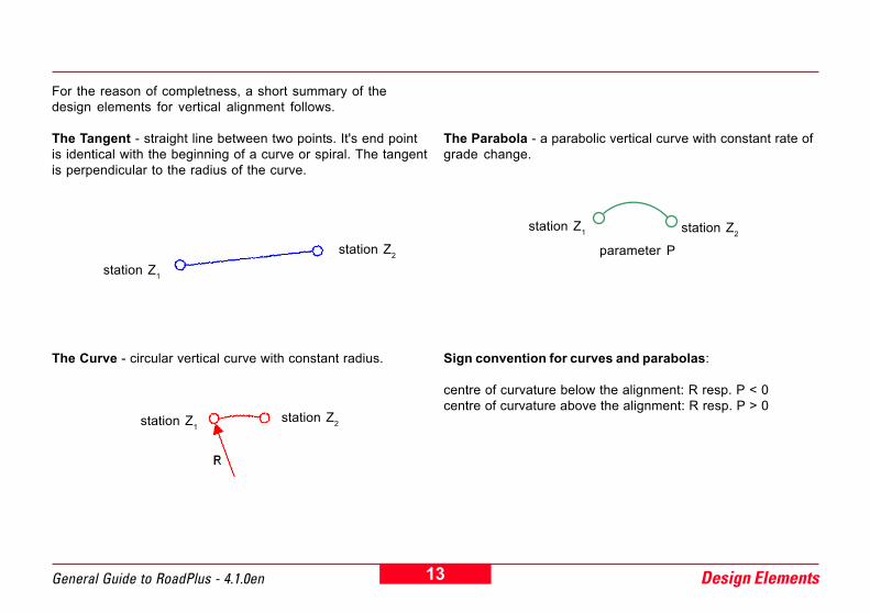
For the reason of completness, a short summary of thedesign elements for vertical alignment follows.
The Tangent - straight line between two points. It's end pointis identical with the beginning of a curve or spiral. The tangentis perpendicular to the radius of the curve.
The Curve - circular vertical curve with constant radius.
The Parabola - a parabolic vertical curve with constant rate ofgrade change.
Sign convention for curves and parabolas:
centre of curvature below the alignment: R resp. P < 0centre of curvature above the alignment: R resp. P > 0
station Z1station Z2
14Design Elements General Guide to RoadPlus - 4.1.0en
1. P = L / (Gout - Gin)
2. P = (S - S0)2 / 2(H - H0)
3. P = 1 / 2a
Parameter P - is the reciprocal of the rate of change of gradein the vertical curve. Three formulas for the calculation of Pexist:
L length as horizontal distance from the beginning to theend of the vertical curve
Gin grade of the vertical alignment at the beginning of thevertical curve
Gout grade of the vertical alignment at the end of the curve
Gin and Gout in decimal units (not percent) negative fordecreasing elevation with increasing station.
S any station (chainage) on the parabolaS0 station (chainage) of the high/low point of the parabolaH height at any station S of the parabolaH0 height of the high / low point of the parabola
whereas a is a parameter in the general equation for aparabola in mathematics Y = aX2 + bX + c.
Y elevation of vertical curve above datumX horizontal distance from the beginning of the vertical
curvea one half of the rate of change of grade in the vertical
curveb Grade of the vertical alignment at the beginning of the
vertical curvec elevation above datum at the beginning of the vertical
curve
15 Design ElementsGeneral Guide to RoadPlus - 4.1.0en
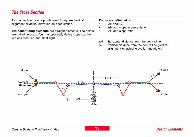
The Cross Section
A cross section gives a profile view. It requires verticalalignment or actual elevation on each station.
The constituting elements are straight elements. The pointsare called vertices. You may optionally define slopes at thevertices most left and most right.
Points are definined by:� ∆H and ∆V� ∆H and slope in percentage� ∆H and slope ratio
∆H horizontal distance from the centre line∆V vertical distance from the centre line (vertical
alignment or actual elevation mandatory)
16Design Elements General Guide to RoadPlus - 4.1.0en
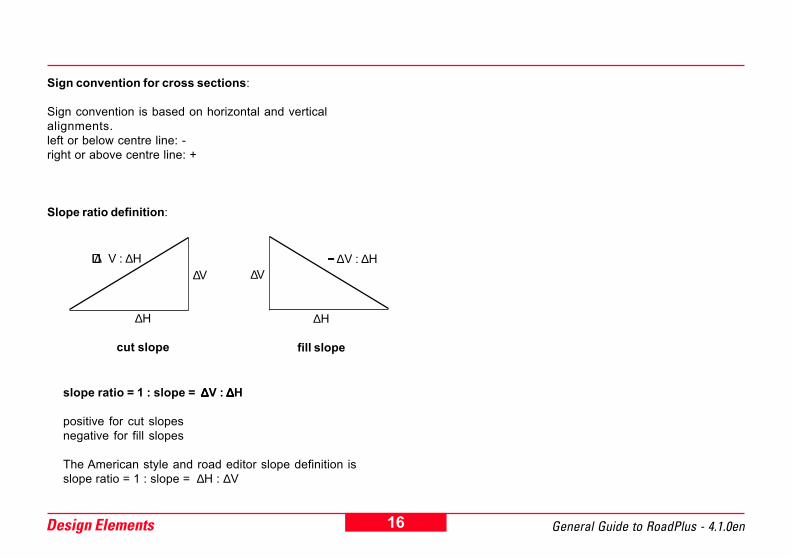
slope ratio = 1 : slope = ∆∆∆∆∆V : ∆∆∆∆∆H
positive for cut slopesnegative for fill slopes
The American style and road editor slope definition isslope ratio = 1 : slope = ∆H : ∆V
Sign convention for cross sections:
Sign convention is based on horizontal and verticalalignments.left or below centre line: -right or above centre line: +
Slope ratio definition:
+++++ ∆V : ∆H
∆H
cut slope
∆V
∆H
fill slope
∆V−−−−− ∆V : ∆H

17 Design ElementsGeneral Guide to RoadPlus - 4.1.0en
The Cross Section Assignment
Cross sections are assigned to stations not to sections.One cross section is valid until a new one is defined at astation ahead.
Cross section definition can be at any station. The stationsneed not necessarily correspond to stations where a designelement starts or ends.
18Design Elements General Guide to RoadPlus - 4.1.0en
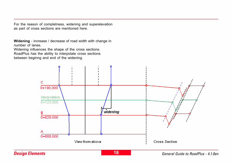
For the reason of completness, widening and superelevationas part of cross sections are mentioned here.
Widening - increase / decrease of road width with change innumber of lanes.Widening influences the shape of the cross sections.RoadPlus has the ability to interpolate cross sectionsbetween beginng and end of the widening.

19 Design ElementsGeneral Guide to RoadPlus - 4.1.0en
Superelevation - modification of the normal pavement crossslope. Intended to increase comfort and safety at speed.
20Design Elements General Guide to RoadPlus - 4.1.0en
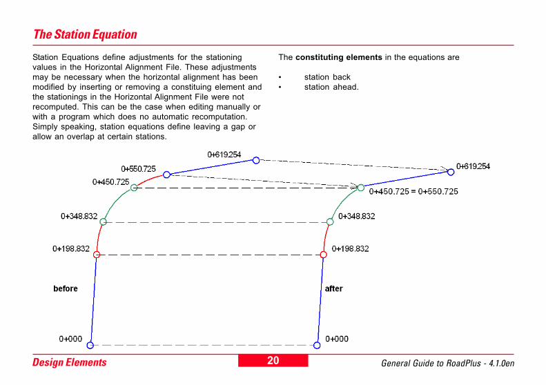
The Station Equation
Station Equations define adjustments for the stationingvalues in the Horizontal Alignment File. These adjustmentsmay be necessary when the horizontal alignment has beenmodified by inserting or removing a constituing element andthe stationings in the Horizontal Alignment File were notrecomputed. This can be the case when editing manually orwith a program which does no automatic recomputation.Simply speaking, station equations define leaving a gap orallow an overlap at certain stations.
The constituting elements in the equations are
� station back� station ahead.

21 Design ElementsGeneral Guide to RoadPlus - 4.1.0en
Station Ahead y+yyy = Station Back x+xxx Station Ahead y+yyy = Station Back x+xxx
Due to removing a constituing element, the sequence ofstationing misses some values. If this is the case, a gapequation (forward station equation) is required. The stationequation is of the form:
The stations between 0+450.725 and 0+550.725 will beignored.
Where the sequence of stationing repeats some values afterinserting a design element, we speak of an overlap equation(backward station equation). Then, the equation is of theform:
Stations between 0+450.725 and 0+550.725 exist twice andrequire re-organizing.

22Data Files and Formats General Guide to RoadPlus - 4.1.0en
Data Files and FormatsAs mentioned in the chapter "Design Elements", a roadsurface is described by three different design elements -horizontal alignment, vertical alignment and cross section.
RoadPlus reads the elements of each of these componentsfrom individual data files that are in the Leica GSI file format.In addition, a file can be created for entering cross-sectionstations for specific locations such as points needed forstaking of superelevation points. Furthermore, if stationequations are needed, RoadPlus will read a file created forstation equations and apply the appropriate corrections.
Since all RoadPlus project files are in GSI format, the com-mon extensions is .gsi, however they are distinguished bythree letter file name prefixes which define the file type andmust be used when creating the files. The question marks inthe example file names may be replaced with any DOSpermitted file name character.
Horizontal Alignment File ALN?????.GSImandatory
Vertical Alignment File PRF?????.GSIoptional
Cross Section (Template) File CRS?????.GSIoptional
Cross Section Assignment File STA?????.GSIoptional
Station Equation File EQN?????.GSIoptional

23 Data Files and FormatsGeneral Guide to RoadPlus - 4.1.0en
The Horizontal Alignment File
Example for a Horizontal Alignment File in Leica GSI format
All parameters describing the constituting elements of a horizontal alignment build a so called Horizontal Alignment File. Thefollowing is an example of a Horizontal Alignment File in Leica GSI8 format. GSI16 is also supported.A Horizontal Alignment File must contain at least a header and two elements. The last element must be EOP.
Note that each line must end with a space and that a CR/LF is required after the last data line.

24Data Files and Formats General Guide to RoadPlus - 4.1.0en
Header of a Horizontal Alignment File in Leica GSI format
The header is the first line in the GSI file. There is only one header line per file.The header line takes the following form:
41....+0EXAMPLE 42....+HZALIGNM 43....+STACOORD
14IW .resuybdenifedebyam,sretcarahcIICSA8mumixam,noitacifitnediboJ
24IW .MNGILAZH+ebtsumyrtnesihT.resuybdegnahcebtonyam,eliFtnemngilAlatnoziroHfonoitacifitnedI
34IW .DROOCATS+ebtsumyrtnesihT.resuybdegnahcebtonyam,elifepyttnioplapicnirpfonoitacifitnedI
25 Data Files and FormatsGeneral Guide to RoadPlus - 4.1.0en
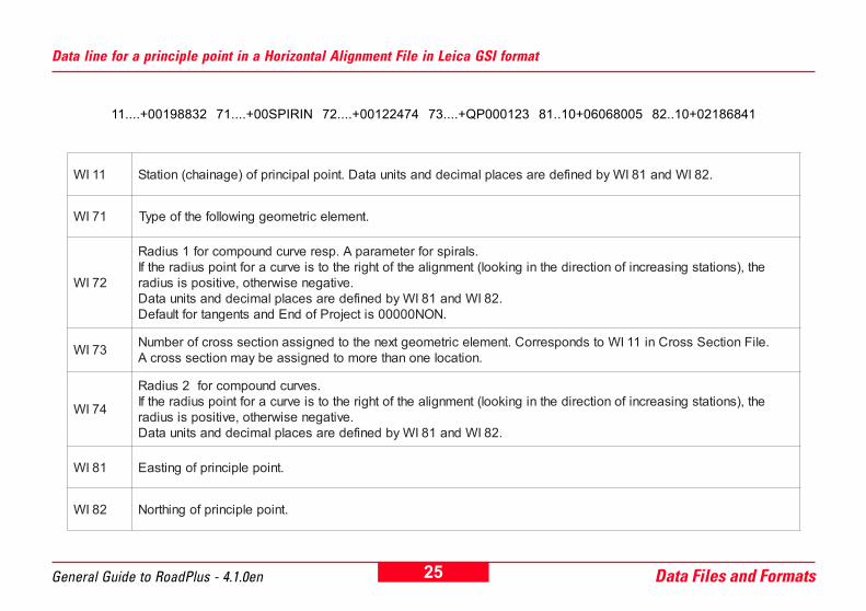
Data line for a principle point in a Horizontal Alignment File in Leica GSI format
11....+00198832 71....+00SPIRIN 72....+00122474 73....+QP000123 81..10+06068005 82..10+02186841
11IW .28IWdna18IWybdenifederasecalplamiceddnastinuataD.tnioplapicnirpfo)eganiahc(noitatS
17IW .tnemelecirtemoeggniwollofehtfoepyT
27IW
.slaripsrofretemarapA.pserevrucdnuopmocrof1suidaReht,)snoitatsgnisaercnifonoitceridehtnignikool(tnemngilaehtfothgirehtotsievrucaroftniopsuidarehtfI
.evitagenesiwrehto,evitisopsisuidar.28IWdna18IWybdenifederasecalplamiceddnastinuataD
.NON00000sitcejorPfodnEdnastnegnatroftluafeD
37IW .eliFnoitceSssorCni11IWotsdnopserroC.tnemelecirtemoegtxenehtotdengissanoitcesssorcforebmuN.noitacolenonahteromotdengissaebyamnoitcesssorcA
47IW
.sevrucdnuopmocrof2suidaReht,)snoitatsgnisaercnifonoitceridehtnignikool(tnemngilaehtfothgirehtotsievrucaroftniopsuidarehtfI
.evitagenesiwrehto,evitisopsisuidar.28IWdna18IWybdenifederasecalplamiceddnastinuataD
18IW .tniopelpicnirpfognitsaE
28IW .tniopelpicnirpfognihtroN

26Data Files and Formats General Guide to RoadPlus - 4.1.0en
The following table shows for all possible elements of a horizontal alignment, the variables and predefined names which arerequired for each WI in a Horizontal Alignment File.
tnemelE 11IW 17IW 27IW 37IW 47IW 18IW 28IW
tnegnaT noitatS THGIARTS NON00000 noitceSssorCrebmuN gnitsaE gnihtroN
evruCralucriC noitatS EVRUC000 R noitceSssorCrebmuN gnitsaE gnihtroN
-laripSevruCottnegnaT noitatS NIRIPS00 A noitceSssorC
rebmuN gnitsaE gnihtroN
-laripStnegnaTotevruC noitatS TUORIPS0 A noitceSssorC
rebmuN gnitsaE gnihtroN
-laripS)2R>1R(evruCotevruC noitatS NIEVRUC0 1R noitceSssorC
rebmuN 2R gnitsaE gnihtroN
-laripS)2R<1R(evruCotevruC noitatS TUOEVRUC 1R noitceSssorC
rebmuN 2R gnitsaE gnihtroN
POE noitatS POE00000 NON00000 gnitsaE gnihtroN
27 Data Files and FormatsGeneral Guide to RoadPlus - 4.1.0en
The Vertical Alignment File
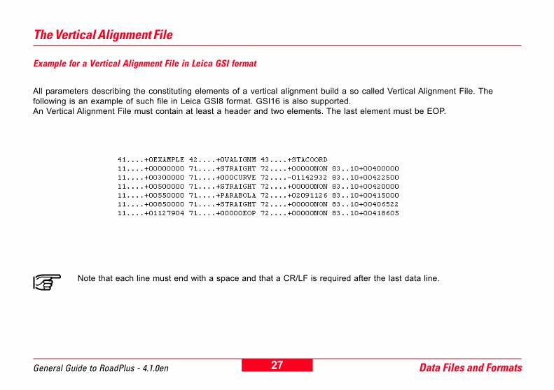
Example for a Vertical Alignment File in Leica GSI format
All parameters describing the constituting elements of a vertical alignment build a so called Vertical Alignment File. Thefollowing is an example of such file in Leica GSI8 format. GSI16 is also supported.An Vertical Alignment File must contain at least a header and two elements. The last element must be EOP.
Note that each line must end with a space and that a CR/LF is required after the last data line.
28Data Files and Formats General Guide to RoadPlus - 4.1.0en
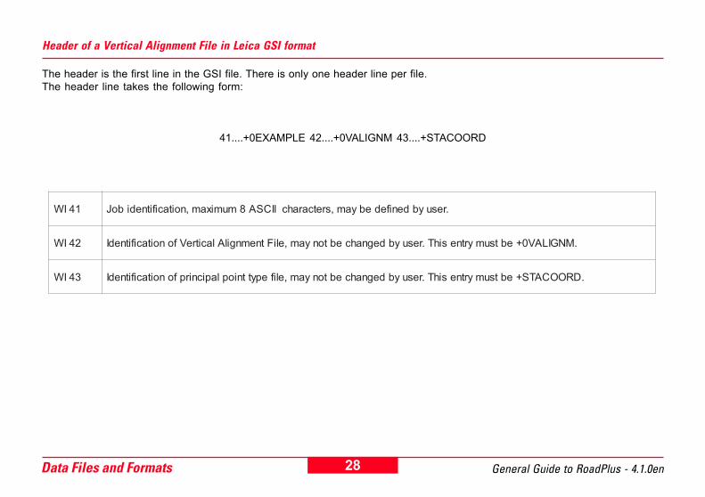
Header of a Vertical Alignment File in Leica GSI format
The header is the first line in the GSI file. There is only one header line per file.The header line takes the following form:
41....+0EXAMPLE 42....+0VALIGNM 43....+STACOORD
14IW .resuybdenifedebyam,sretcarahcIICSA8mumixam,noitacifitnediboJ
24IW .MNGILAV0+ebtsumyrtnesihT.resuybdegnahcebtonyam,eliFtnemngilAlacitreVfonoitacifitnedI
34IW .DROOCATS+ebtsumyrtnesihT.resuybdegnahcebtonyam,elifepyttnioplapicnirpfonoitacifitnedI
29 Data Files and FormatsGeneral Guide to RoadPlus - 4.1.0en
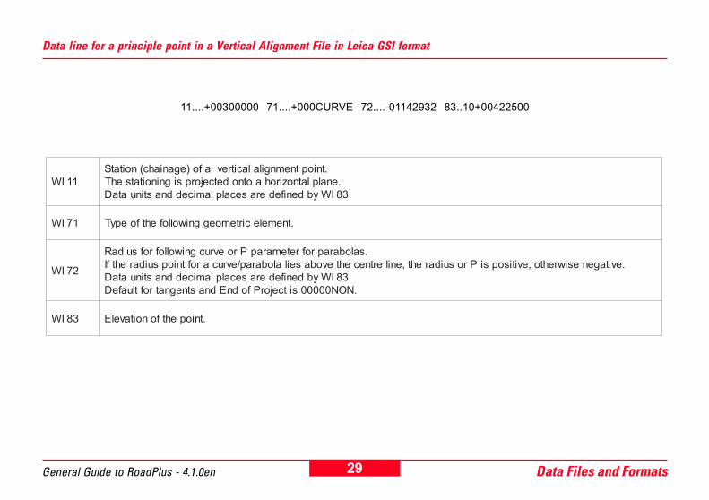
Data line for a principle point in a Vertical Alignment File in Leica GSI format
11....+00300000 71....+000CURVE 72....-01142932 83..10+00422500
11IW.tnioptnemngilalacitrevafo)eganiahc(noitatS.enalplatnozirohaotnodetcejorpsigninoitatsehT.38IWybdenifederasecalplamiceddnastinuataD
17IW .tnemelecirtemoeggniwollofehtfoepyT
27IW
.salobaraprofretemarapProevrucgniwollofrofsuidaR.evitagenesiwrehto,evitisopsiProsuidareht,enilertnecehtevobaseilalobarap/evrucaroftniopsuidarehtfI
.38IWybdenifederasecalplamiceddnastinuataD.NON00000sitcejorPfodnEdnastnegnatroftluafeD
38IW .tniopehtfonoitavelE
30Data Files and Formats General Guide to RoadPlus - 4.1.0en
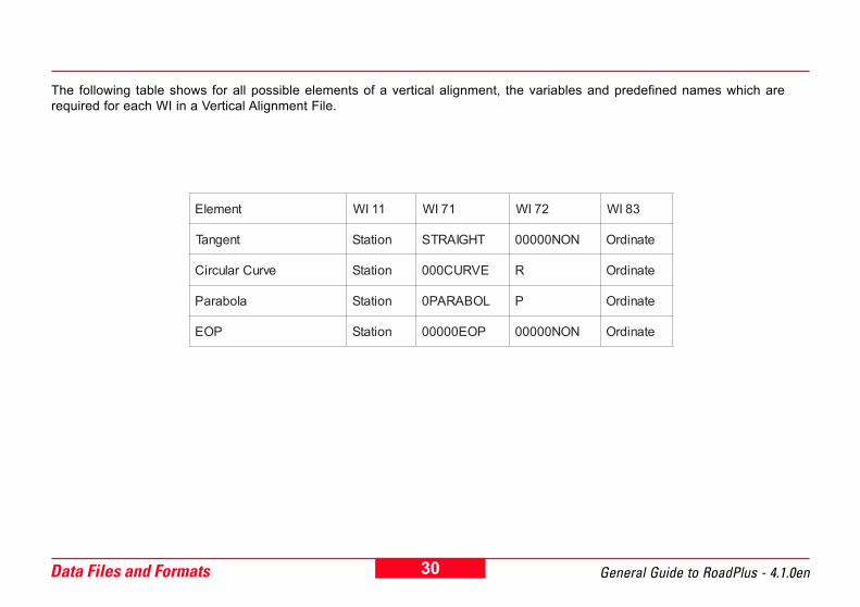
The following table shows for all possible elements of a vertical alignment, the variables and predefined names which arerequired for each WI in a Vertical Alignment File.
tnemelE 11IW 17IW 27IW 38IW
tnegnaT noitatS THGIARTS NON00000 etanidrO
evruCralucriC noitatS EVRUC000 R etanidrO
alobaraP noitatS LOBARAP0 P etanidrO
POE noitatS POE00000 NON00000 etanidrO

31 Data Files and FormatsGeneral Guide to RoadPlus - 4.1.0en
The Cross Section (Template) File
Example for a Cross Section File in Leica GSI formatAll parameters describing the constituting elements of a cross section build a so called Cross Section (or Template) File. Thefollowing is an example of such a file in Leica GSI8 format. GSI16 is also supported.A Cross Section File must contain at least one cross section. 200 cross sections per file are allowed. One cross section maybe described by up to 64 vertices (points).
Note that each line must end with a space and that a CR/LF is required after the last data line.

32Data Files and Formats General Guide to RoadPlus - 4.1.0en
Header of a Cross Section File in Leica GSI format
The header is the first line in the GSI file. There is only one header line per file.The header line takes the following form:
41....+0EXAMPLE 42....+TEMPLATE
14IW .resuybdenifedebyam,sretcarahcIICSA8mumixam,noitacifitnediboJ
24IW .ETALPMET+ebtsumyrtnesihT.resuybdegnahcebtonyam,eliFnoitceSssorCfonoitacifitnedI

33 Data Files and FormatsGeneral Guide to RoadPlus - 4.1.0en
Data line for a vertex in a Cross Section File in Leica GSI format
11....+QP000124 35..10+00012000 36..10-0000250011....+TEMPLATE 35..10-00002000 36..10+00000000 71....+0000FILL 72....+00002000
11IW
.eliFtnemngilAlatnoziroHehtni37IWotsdnopserroc,rebmunnoitcesssorC.redrognidnecsedro-saniebtondeensrebmunnoitcesssorC
.rehtegottpekebdluohsdnarehtegotgnolebrebmunnoitcesssorcemasehtgnivahsenilatadlla,revewoH.noitcesehtssorcathgirottfelmorfdetrosebtsumnoitcesssorcenorofsenilatadehT
53IW.enilertnecmorfecnatsidlatnoziroH
.enilertnecehtfothgirehtottniopasetacidniecnatsidevitisopA.enilertnecehtfotfelehtottniopasetacidniecnatsidevitagenA
63IW.enilertnecehtmorfecnereffidthgieH
.enilertnecehtevobatniopasetacidniecnereffidthgiehevitisopA.enilertnecehtwolebtniopasetacidniecnereffidthgiehevitagenA
17IW .lanoitpo;epytnoitcesssorC
27IW.lanoitpo;)noitceSssorCretpahceesnoitinifed(Vd/HdsaoitarepolS
.noitcesssorcanistnioptsomthgirdnatsomtfeltubllarofdewolla0.63IWdna53IWybdenifedstinuataD

34Data Files and Formats General Guide to RoadPlus - 4.1.0en
The following table shows the two possibilities for defining vertices of a cross section and the predefined names which arerequired for each WI in a Cross Section File.
tnemelE 11IW 53IW 63IW 17IW 27IW
xetreV)tnemngilalacitrevgnisu(
noitceSssorCrebmuN
latnoziroHtesffO
lacitreVtesffO
TUC00000LLIF0000 epolS
xetreVlacitrevtuohtiw(
)tnemngila
noitceSssorCrebmuN
latnoziroHtesffO noitavelE TUC00000
LLIF0000 epolS

35 Data Files and FormatsGeneral Guide to RoadPlus - 4.1.0en
The Cross Section Assignment File
Example for a Cross Section Assignment File in Leica GSI format
The Cross Section Assignment File defines the stations for the cross sections. Note that the stations given for the crosssections do not necessarily correspond to stations where design elements start or end. The following is an example of such afile in Leica GSI8 format. GSI16 is also supported.A Cross Section Assignment File belongs to a corresponding Cross Section File. You must have a Cross Section AssignmentFile when using a Cross Section File. The number of assignments is restricted to 100 per file. A cross section remains validuntil a new cross section is assigned. A given cross section may be assigned more than once. Automatic transitions such aswidth and superelevation are possible.
Note that each line must end with a space and that a CR/LF is required after the last data line.
36Data Files and Formats General Guide to RoadPlus - 4.1.0en
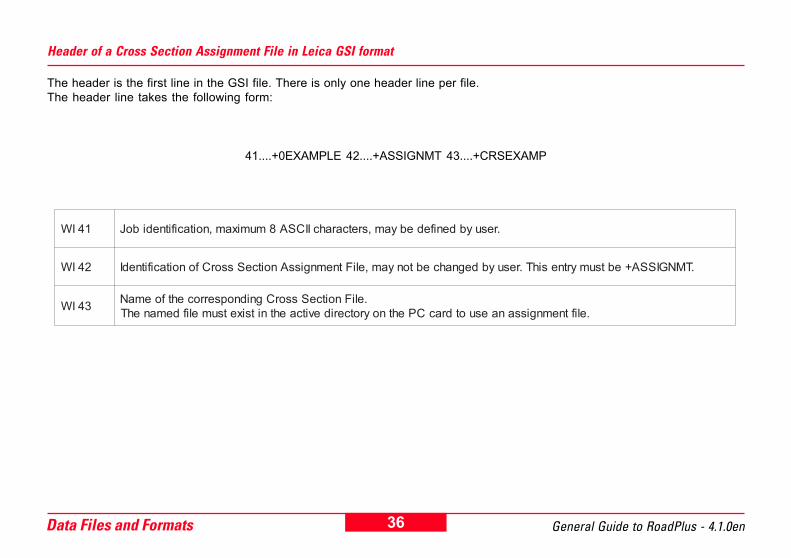
Header of a Cross Section Assignment File in Leica GSI format
The header is the first line in the GSI file. There is only one header line per file.The header line takes the following form:
41....+0EXAMPLE 42....+ASSIGNMT 43....+CRSEXAMP
14IW .resuybdenifedebyam,sretcarahcIICSA8mumixam,noitacifitnediboJ
24IW .TMNGISSA+ebtsumyrtnesihT.resuybdegnahcebtonyam,eliFtnemngissAnoitceSssorCfonoitacifitnedI
34IW .eliFnoitceSssorCgnidnopserrocehtfoemaN.eliftnemngissanaesuotdracCPehtnoyrotceridevitcaehtnitsixetsumelifdemanehT

37 Data Files and FormatsGeneral Guide to RoadPlus - 4.1.0en
Data line in a Cross Section Assignment File in Leica GSI format
11....+QP000123 71....+00100000
For the matter of completion, the following table is added as in the previous chapters.
11IW .eliFtnemngilAlatnoziroHehtni37IWdnaeliFnoitceSssorCehtni11IWotsdnopserroc,rebmunnoitcesssorC
17IW .noitcesssorcralucitrapehtrofeganiahcgninnigeB
tnemelE 11IW 17IW
tnemngissA rebmuNnoitceSssorC noitatS

38Data Files and Formats General Guide to RoadPlus - 4.1.0en
The Station Equation File
Example for a Station Equation File in Leica GSI format
The Station Equation File re-defines horizontal alignments after adding / removing constituing elements. Station Equation Filesare optional for RoadPlus and only required when stationings have not been recomputed after changes in the HorizontalAlignment File. The number of equations per file is limited to 100.The following is an example of such a file in Leica GSI8 format. GSI16 is also supported.
Note that each line must end with a space and that a CR/LF is required after the last data line.
If you use the Leica program RoadEd for your editing, you really should not need to use a station equation file because it willalways attempt to adjust the stationings for you as you make changes. You can also force it to re-calculate the stationing usingthe Recalc Stationings command from the menu. However, RoadEd does support the creation and editing of these files if theyare needed. Be aware of the fact that RoadEd does not read the station equation file when it checks for errors in youralignment. You can ignore stationing errors which you have corrected using a station equation file.
39 Data Files and FormatsGeneral Guide to RoadPlus - 4.1.0en
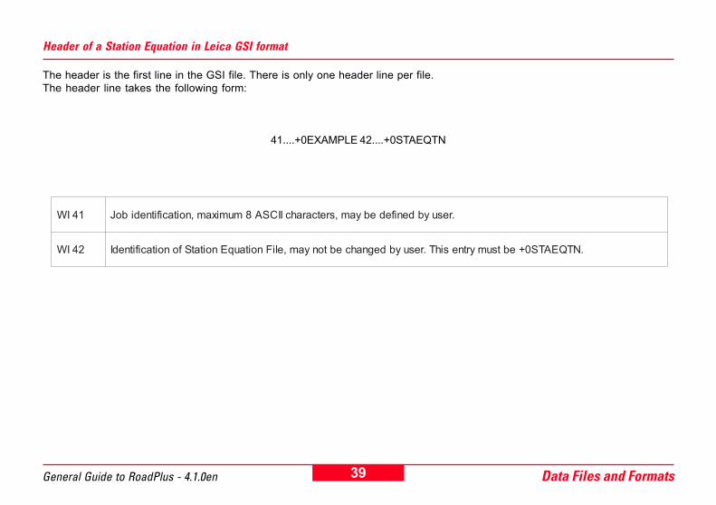
Header of a Station Equation in Leica GSI format
The header is the first line in the GSI file. There is only one header line per file.The header line takes the following form:
41....+0EXAMPLE 42....+0STAEQTN
14IW .resuybdenifedebyam,sretcarahcIICSA8mumixam,noitacifitnediboJ
24IW .NTQEATS0+ebtsumyrtnesihT.resuybdegnahcebtonyam,eliFnoitauqEnoitatSfonoitacifitnedI
40Data Files and Formats General Guide to RoadPlus - 4.1.0en
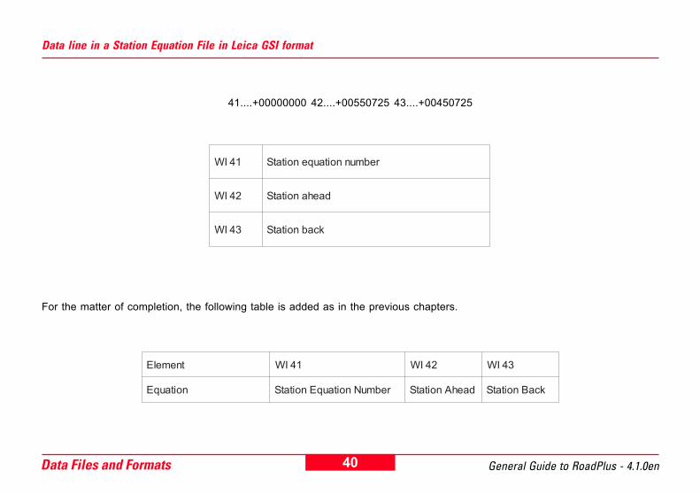
Data line in a Station Equation File in Leica GSI format
41....+00000000 42....+00550725 43....+00450725
For the matter of completion, the following table is added as in the previous chapters.
14IW rebmunnoitauqenoitatS
24IW daehanoitatS
34IW kcabnoitatS
tnemelE 14IW 24IW 34IW
noitauqE rebmuNnoitauqEnoitatS daehAnoitatS kcaBnoitatS

41 Data Files and FormatsGeneral Guide to RoadPlus - 4.1.0en
Creating RoadPlus project files
The data files is GSI format can be created either by using theLeica program RoadEd or by converting files from differentroad packages.
RoadEd is a basic tool intended for quick and easy creation ofnew alignments or modification of existing ones. It alsosupports checking alignments for errors and plottingalignments on a graph.
Some commercial road packages such as
� TopoCAD (Sweden)� Geo11 (Sweden)� GEOSECMA NT (Sweden)
save the data directly in GSI format.
Other road packages have their own file format for whichconversion programs to GSI exist, for example
� Microstation with Intergraph Inroads as add-on(worldwide)
� CARD1 (Germany)� REB (Germany)� MOSS (UK)� NRG (UK).

42Data Files and Formats General Guide to RoadPlus - 4.1.0en
Copy the data files to the PCMCIA card Transferring the data files directly from the PC to the card
Once the data files have been created, they need to be copiedto the PCMCIA card.If your computer has a PC card reader, you can transfer thedata files directly from the PC to the card. If no PC card readeris available on the PC being used, use the sensor transferoption in SKI-Pro.
Ø Format the PCMCIA card in the sensor.Ø Insert the card into the PC.Ø By using the Explorer, copy the data files from the hard driveof the PC into the directory GSI on the memory card.
43 Data Files and FormatsGeneral Guide to RoadPlus - 4.1.0en
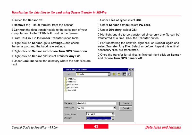
Transferring the data files to the card using Sensor Transfer in SKI-Pro
Ø Switch the Sensor off.Ø Remove the TR500 terminal from the sensor.Ø Connect the data transfer cable to the serial port of yourcomputer and to the TERMINAL port on the Sensor.Ø Start SKI-Pro. Go to Sensor Transfer under Tools.Ø Right-click on Sensor, go to Settings... and checkthe serial port and the baud rate settings.Ø Right-click on Sensor and choose Turn GPS Sensor on.Ø Right-click on Sensor and select Transfer Any File.Ø Under Look in: select the directory where the data files arekept.
Ø Under Files of Type: select GSI.Ø Under Sensor device: select PC-card.Ø Under Directory: select GSI.Ø Highlight one file to be transferred since only one file can betransferred at a time. Click the Transfer button.Ø For transferring the next file, right-click on Sensor again andselect Transfer Any File. Select as before. Repeat this until allnecessary files are transferred.Ø Once the transfer for all files is finished, right-click on Sensorand choose Turn GPS Sensor off.
44Terminology of Road Staking General Guide to RoadPlus - 4.1.0en
Terminology of Road StakingCertain terminology is sometimes used for road staking.They may vary from country to country.In order to make the chapter on staking a road alignment withthe program RoadPlus easier to understand, the basicterminology of one common way of road staking is introducedin this chapter. The technical terms are indicated in thedrawings and are also explained in words afterwards.
45 Terminology of Road StakingGeneral Guide to RoadPlus - 4.1.0en
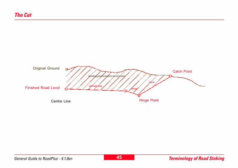
The Cut
Centre Line
Catch PointOriginal Ground
Finished Road Level
Existing ground level to be removed
vergecarriage way
slope
Hinge Point
46Terminology of Road Staking General Guide to RoadPlus - 4.1.0en
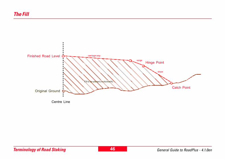
The Fill
Original Ground
Finished Road Level
Centre Line
Catch Point
Fill to be placed (rocks/earth)
verge
carriage way
slope
Hinge Point

47 Terminology of Road StakingGeneral Guide to RoadPlus - 4.1.0en
The part of the road on which you drive once the road isfinished is called carriage way (roadway, travel way).
Next to the carriage way may be the verge (shoulder) withusually a slightly higher slope ratio than the carriage way.
The slope is next to the verge and can be thought of as linkingthe road level with the original ground. Its slope ratio is evenhigher than the one of the verge. A slope starts at the hingepoint.
The original ground / surface is the undisturbed surfacebefore project construction.
The Finished Road Level describes the final road.
Since cuts / fills start from the original ground, there must bea physical point on each desired cross section station wherethe finished design shape of the roadway cut / fill intersectswith the existing ground surface. This point is called catchpoint. If the catch point is marking the catch of a cut slope, it iscalled top of bank (= top). Toe of bank/slope (=toe) is thecatch point marking the catch of a fill slope.
Usually, the stake of the catch point is gone after the initial cut/ fill. An offset catch point is often marked nearby as secondpoint. This point is offset from the catch point.
The Technical Terms
48Staking a Road Alignment General Guide to RoadPlus - 4.1.0en
Staking a Road AlignmentThis chapter of this guide explains the operation of theRoadPlus application program covering the following steps:
� Starting the application� Configuring road stakeout parameters� Selecting the alignment file� Staking uneven stations� Staking cross sections
The Coordinate System
In order to get the correct result when working with RoadPlus,the GPS jobs must be orientated to the same local gridcoordinate system as the alignment to be staked out. This isaccomplished by attaching the current coordinate system tothe job.
Depending on the coordinate system, you will either use pre-defined parameters or determine the required transformationparameters either on the sensor or in SKI-Pro.
On how to set up a coordinate system and on how tocalculate transformation parameters please refer to "GettingStarted with Real-Time Surveys� as well as the "TechnicalReference Manual" for assistance.
49General Guide to RoadPlus - 4.1.0en Staking a Road Alignment
Setting the unitsReceiver set-up
RoadPlus is a real-time application.
Therefore, a properly initialised real-time configuration set isrequired. This means, reference and rover must be set-upproperly running a suitable configuration set and the datatransfer from the reference to the rover must be working.
For detailed information please refer to �Getting Started withReal-Time Surveys� and the "Technical Reference Manual".
The GPS sensors must be configured in the same coordinateunits as those of the generated gsi files.
Check the sensor settings in panel CONFIGURE \ Units.
The units must not be changed while working with RoadPlus.
50Staking a Road Alignment General Guide to RoadPlus - 4.1.0en
Starting the Application
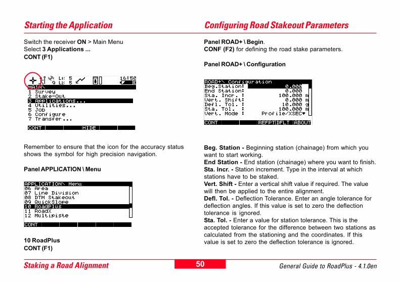
Switch the receiver ON > Main MenuSelect 3 Applications ...CONT (F1)
Panel ROAD+ \ Begin.CONF (F2) for defining the road stake parameters.
Panel ROAD+ \ Configuration
Configuring Road Stakeout Parameters
Remember to ensure that the icon for the accuracy statusshows the symbol for high precision navigation.
Panel APPLICATION \ Menu
10 RoadPlusCONT (F1)
Beg. Station - Beginning station (chainage) from which youwant to start working.End Station - End station (chainage) where you want to finish.Sta. Incr. - Station increment. Type in the interval at whichstations have to be staked.Vert. Shift - Enter a vertical shift value if required. The valuewill then be applied to the entire alignment.Defl. Tol. - Deflection Tolerance. Enter an angle tolerance fordeflection angles. If this value is set to zero the deflectiontolerance is ignored.Sta. Tol. - Enter a value for station tolerance. This is theaccepted tolerance for the difference between two stations ascalculated from the stationing and the coordinates. If thisvalue is set to zero the deflection tolerance is ignored.
51General Guide to RoadPlus - 4.1.0en Staking a Road Alignment
Vert. Mode - Choose between Profile/XSec, DTM and OFF.Profile/XSec allows you to stakeout a vertical alignment andcross sections. DTM uses a pre-defined digital terrain model.Set to OFF when only a horizontal alignment has to be staked.The normal mode is Profile/XSec.
Crs. Intrpl. - The cross section interpolation can be switchedON or OFF. In the case of OFF, a cross section assigned to astation in a Cross Section Assignment File will remaineffective to the next station where another cross section isassigned. The transition between the two cross sections willbe abrupt. When set to ON, all cross sections must consist ofthe same number of points. A linear transition will be appliedto two cross sections defined in the Cross SectionAssignment File. If the project continues past the last stationdefined in the Cross Section Assignment File, the last givencross section will be applied. The interpolation betweencross sections makes the staking out of sections of road withsuperelevation and widening possible.
Crs. Movemnt - There are three choices: Left > Right, Right >Left and None. The direction chosen is for automaticselection of the next station of a cross section. Points can stillbe staked out at any desired direction along the crosssection. None is for no automatic pre-selection.Hinge Mode - Method for the catch point determination. Theoptions are Normal and Not from End Pts. When Normal isselected, the points to the most right or left from the centreline are used for calculating the catch point. Select Not fromEnd Pts, when the catch point is already available in the cross
section file and therefore the points to the most right or leftfrom the centre line are not needed for its calculation.
Log File - If this is set to ON, stake out data can be stored in afile for printing later.
Log FlName - Enter a file name for the log file.
Edit Height - If you wish to edit the elevation of a design pointbefore staking select YES. When changing heights beforestaking, the Log File will be updated accordingly. This is forexample useful if someone would like to manually enter theelevation of the invert level of a manhole and then stakeoutthe manhole's horizontal location in relation to the horizontalalignment and the manhole's invert level without being tied tothe vertical alignment. The default setting is NO.
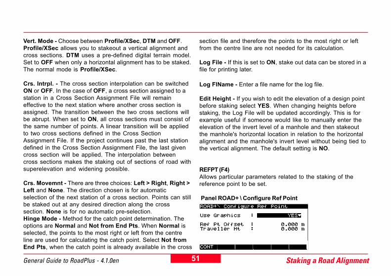
REFPT (F4)Allows particular parameters related to the staking of thereference point to be set.
Panel ROAD+ \ Configure Ref Point
52Staking a Road Alignment General Guide to RoadPlus - 4.1.0en
Selecting the Files
Use Graphics - Allows the reference point to be staked outgraphically.Ref Pt Offset - Defines the offset of the reference point fromthe catch point to be staked out.Traveller Ht - Defines the offest of the slope being staked out.
CONT(F1) returns to the panel ROAD+\ Configuration
DFLT (F5)This sets the default values for all input fields. It may benecessary to adapt them according to your needs.
When all input fields have been set correctly then press CONT(F1). This takes you to the panel ROAD+ \ Begin where youcan select the alignment files.
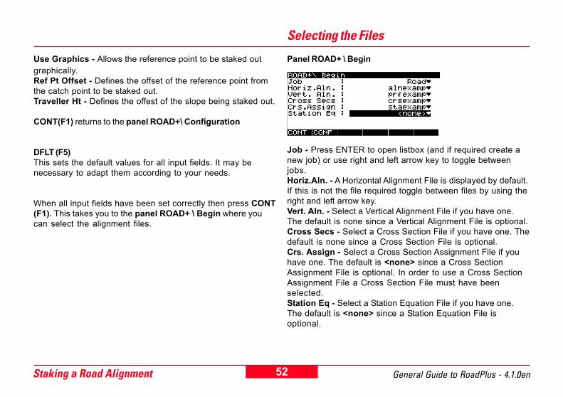
Panel ROAD+ \ Begin
Job - Press ENTER to open listbox (and if required create anew job) or use right and left arrow key to toggle betweenjobs.Horiz.Aln. - A Horizontal Alignment File is displayed by default.If this is not the file required toggle between files by using theright and left arrow key.Vert. Aln. - Select a Vertical Alignment File if you have one.The default is none since a Vertical Alignment File is optional.Cross Secs - Select a Cross Section File if you have one. Thedefault is none since a Cross Section File is optional.Crs. Assign - Select a Cross Section Assignment File if youhave one. The default is <none> since a Cross SectionAssignment File is optional. In order to use a Cross SectionAssignment File a Cross Section File must have beenselected.Station Eq - Select a Station Equation File if you have one.The default is <none> since a Station Equation File isoptional.
53General Guide to RoadPlus - 4.1.0en Staking a Road Alignment
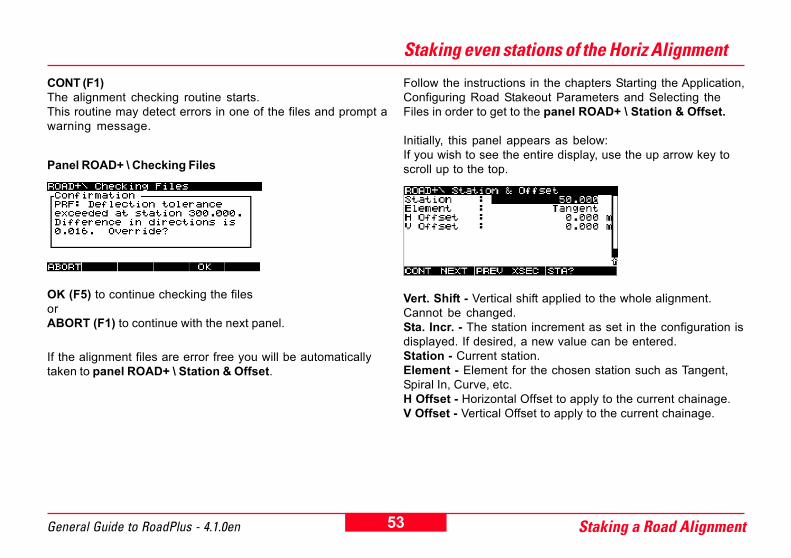
CONT (F1)The alignment checking routine starts.This routine may detect errors in one of the files and prompt awarning message.
Panel ROAD+ \ Checking Files
OK (F5) to continue checking the filesorABORT (F1) to continue with the next panel.
If the alignment files are error free you will be automaticallytaken to panel ROAD+ \ Station & Offset.
Staking even stations of the Horiz Alignment
Follow the instructions in the chapters Starting the Application,Configuring Road Stakeout Parameters and Selecting theFiles in order to get to the panel ROAD+ \ Station & Offset.
Initially, this panel appears as below:If you wish to see the entire display, use the up arrow key toscroll up to the top.
Vert. Shift - Vertical shift applied to the whole alignment.Cannot be changed.Sta. Incr. - The station increment as set in the configuration isdisplayed. If desired, a new value can be entered.Station - Current station.Element - Element for the chosen station such as Tangent,Spiral In, Curve, etc.H Offset - Horizontal Offset to apply to the current chainage.V Offset - Vertical Offset to apply to the current chainage.
54Staking a Road Alignment General Guide to RoadPlus - 4.1.0en
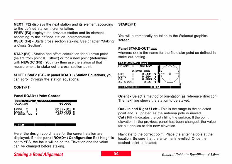
NEXT (F2) displays the next station and its element accordingto the defined station incrementation.PREV (F3) displays the previous station and its elementaccording to the defined station incrementation.XSEC (F4) - Starts cross section staking. See chapter "Stakinga Cross Section".
STA? (F5) - Station and offset calculation for a known point(select from point ID listbox) or for a new point (determinewith NEWOC (F5)). You may then use the station of thatmeasurement to stake out a cross section point.
SHIFT + StaEq (F4) - In panel ROAD+ \ Station Equations, youcan scroll through the station equations.
STAKE (F1)
CONT (F1)
Panel ROAD+ \ Point Coords
You will automatically be taken to the Stakeout graphicsscreen.
Panel STAKE-OUT \ xxxwhereas xxx is the name for the file stake point as defined instake out setting.
Orient - Select a method of orientation as reference direction.The next line shows the station to be staked.
Out / In and Right / Left - This is the range to the selectedpoint and is updated as the antenna pole is moved.Cut / Fill - Indicates the cut / fill to the surface. If the pointelevation in the previous panel has been changed, the valuefor cut applies to this new elevation.
Navigate to the correct point. Place the antenna pole at thelocation. Be sure that the antenna is levelled. Once thedesired point is located:
Here, the design coordinates for the current station aredisplayed. If in the panel ROAD+ \ Configuration Edit Height isset to YES, the focus will be on the Elevation and the valuecan be changed before staking.

55General Guide to RoadPlus - 4.1.0en Staking a Road Alignment
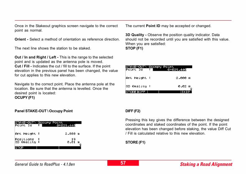
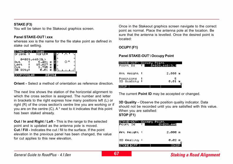
OCUPY (F1)
Panel STAKE-OUT \ Occupy Point
The current Point ID may be accepted or changed.
3D Quality - Observe the position quality indicator. Datashould not be recorded until you are satisfied with this value.When you are satisfied:STOP (F1)
DIFF (F2)
Pressing this key gives the difference between the designedcoordinates and staked coordinates of the point. If the pointelevation has been changed before staking, the value Diff Cut/ Fill is calculated relative to this new elevation.STORE (F1)
The system returns to panel ROAD+ \ Station & Offset wherethe station has incremented by the station increment value.
Repeat the steps before to stake-out additional stationsalong the alignment.
Once the last point (EOP) in the Horizontal Alignment File hasbeen staked and you continue anyway, this confirmationmessage will appear:
OK (F5) and then CONT (F1) to continue anywayorABORT (F1) and ESC to exit the panel.
For complete information on how to use STAKE-OUT pleaserefer to chapter "Real-Time Rover, Staking Out" in the "Techni-cal Reference Manual".

56Staking a Road Alignment General Guide to RoadPlus - 4.1.0en
Staking uneven stations of the Horizontal Alignment
It is often required to stake stations that are not on the evenstation as defined by the station interval. The steps belowdescribe how to stake a station at an uneven station.
Follow the instructions in the chapters Starting the Application,Configuring Road Stakeout Parameters and Selecting theFiles in order to get to the panel ROAD+ \ Station & Offset.
Station - Manually enter the uneven station.H Offset - Horizontal offset to be applied to current station.Looking in the direction of increasing station, apply the "righthand positive rule".V Offset - Vertical offset to be applied to current station. Apositive offset is above, a negative offset is below the normalheight of the current station.
CONT (F1)
Panel ROAD+ \ Point Coords
Here, the design coordinates for the current uneven stationare displayed. If in the panel ROAD+ \ Configuration EditHeight is set to YES, the focus will be on the Elevation and thevalue can be changed before staking.
STAKE (F1)
You will automatically be taken to the Stakeout graphicsscreen.
Panel STAKE-OUT \ xxxwhereas xxx is the name for the file stake point as defined instake out setting.
57General Guide to RoadPlus - 4.1.0en Staking a Road Alignment
Once in the Stakeout graphics screen navigate to the correctpoint as normal.
Orient - Select a method of orientation as reference direction.
The next line shows the station to be staked.
Out / In and Right / Left - This is the range to the selectedpoint and is updated as the antenna pole is moved.Cut / Fill - Indicates the cut / fill to the surface. If the pointelevation in the previous panel has been changed, the valuefor cut applies to this new elevation.
Navigate to the correct point. Place the antenna pole at thelocation. Be sure that the antenna is levelled. Once thedesired point is located:OCUPY (F1)
Panel STAKE-OUT \ Occupy Point
The current Point ID may be accepted or changed.
3D Quality - Observe the position quality indicator. Datashould not be recorded until you are satisfied with this value.When you are satisfied:STOP (F1)
DIFF (F2)
Pressing this key gives the difference between the designedcoordinates and staked coordinates of the point. If the pointelevation has been changed before staking, the value Diff Cut/ Fill is calculated relative to this new elevation.
STORE (F1)
58Staking a Road Alignment General Guide to RoadPlus - 4.1.0en
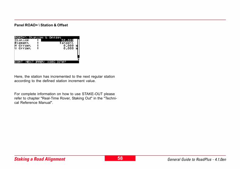
Panel ROAD+ \ Station & Offset
Here, the station has incremented to the next regular stationaccording to the defined station increment value.
For complete information on how to use STAKE-OUT pleaserefer to chapter "Real-Time Rover, Staking Out" in the "Techni-cal Reference Manual".
59General Guide to RoadPlus - 4.1.0en Staking a Road Alignment
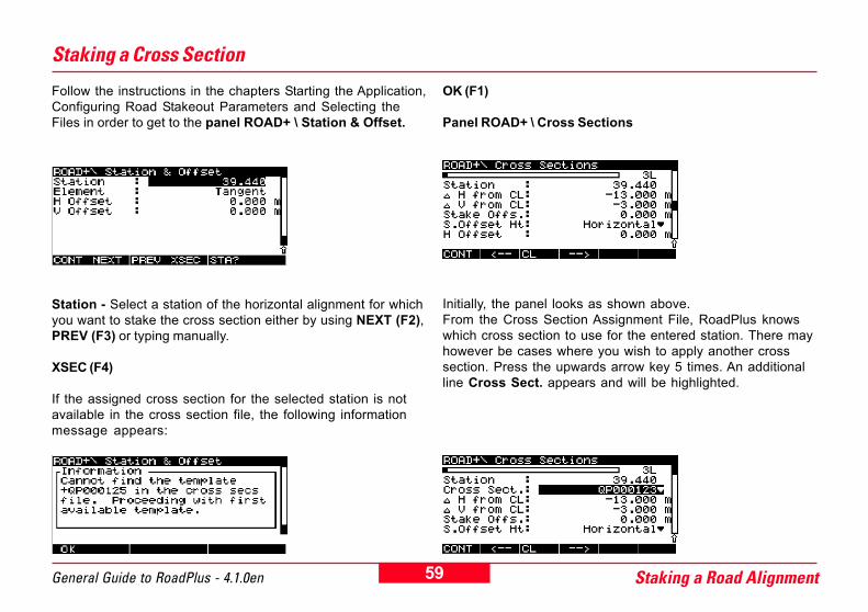
Follow the instructions in the chapters Starting the Application,Configuring Road Stakeout Parameters and Selecting theFiles in order to get to the panel ROAD+ \ Station & Offset.
Station - Select a station of the horizontal alignment for whichyou want to stake the cross section either by using NEXT (F2),PREV (F3) or typing manually.
XSEC (F4)
If the assigned cross section for the selected station is notavailable in the cross section file, the following informationmessage appears:
Staking a Cross Section
Initially, the panel looks as shown above.From the Cross Section Assignment File, RoadPlus knowswhich cross section to use for the entered station. There mayhowever be cases where you wish to apply another crosssection. Press the upwards arrow key 5 times. An additionalline Cross Sect. appears and will be highlighted.
OK (F1)
Panel ROAD+ \ Cross Sections
60Staking a Road Alignment General Guide to RoadPlus - 4.1.0en
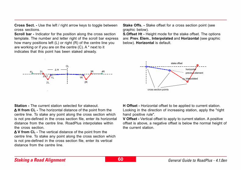
Cross Sect. - Use the left / right arrow keys to toggle betweencross sections.Scroll bar - Indicator for the position along the cross sectiontemplate. The number and letter right of the scroll bar expresshow many positions left (L) or right (R) of the centre line youare working or if you are on the centre (C). A * next to itindicates that this point has been staked already.
Station - The current station selected for stakeout.∆∆∆∆∆ H from CL - The horizontal distance of the point from thecentre line. To stake any point along the cross section whichis not pre-defined in the cross section file, enter its horizontaldistance from the centre line. RoadPlus interpolates withinthe cross section.∆∆∆∆∆ V from CL - The vertical distance of the point from thecentre line. To stake any point along the cross section whichis not pre-defined in the cross section file, enter its verticaldistance from the centre line.
H Offset - Horizontal offset to be applied to current station.Looking in the direction of increasing station, apply the "righthand positive rule".V Offset - Vertical offset to apply to current station. A positiveoffset is above, a negative offset is below the normal height ofthe current station.
Stake Offs. - Stake offset for a cross section point (seegraphic below).S.Offset Ht - Height mode for the stake offset. The optionsare: Prev. Elem., Interpolated and Horizontal (see graphicbelow). Horizontal is default.
stake offset
cross section points
horizontalprevious element
interpolated
CL
1 L
2 L
3 L4 L
1R
2R
3R 4R
∆ V
∆ H
61General Guide to RoadPlus - 4.1.0en Staking a Road Alignment
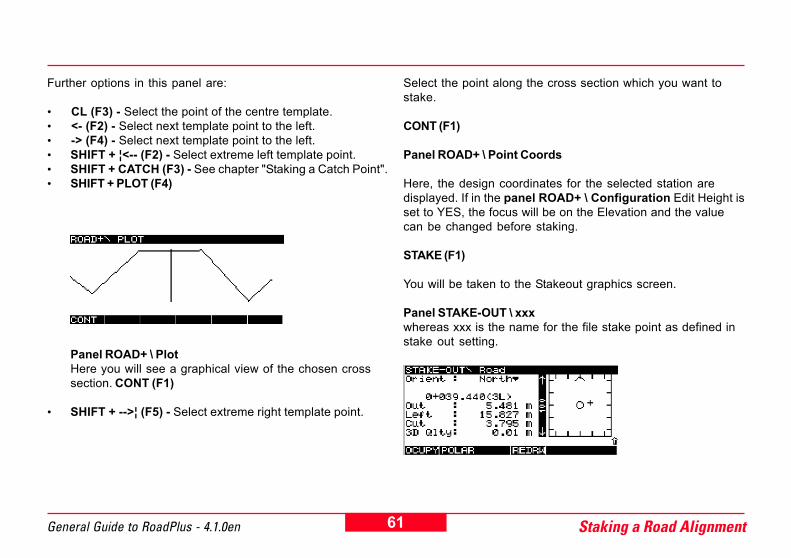
Further options in this panel are:
� CL (F3) - Select the point of the centre template.� <- (F2) - Select next template point to the left.� -> (F4) - Select next template point to the left.� SHIFT + ¦<-- (F2) - Select extreme left template point.� SHIFT + CATCH (F3) - See chapter "Staking a Catch Point".� SHIFT + PLOT (F4)
Select the point along the cross section which you want tostake.
CONT (F1)
Panel ROAD+ \ Point Coords
Here, the design coordinates for the selected station aredisplayed. If in the panel ROAD+ \ Configuration Edit Height isset to YES, the focus will be on the Elevation and the valuecan be changed before staking.
STAKE (F1)
You will be taken to the Stakeout graphics screen.
Panel STAKE-OUT \ xxxwhereas xxx is the name for the file stake point as defined instake out setting.
Panel ROAD+ \ PlotHere you will see a graphical view of the chosen crosssection. CONT (F1)
� SHIFT + -->¦ (F5) - Select extreme right template point.

62Staking a Road Alignment General Guide to RoadPlus - 4.1.0en
Orient - Select a method of orientation as reference direction.
The next line shows the station of the horizontal alignment towhich the cross section is assigned. The number and letterin brackets to the right express how many positions left (L) orright (R) of the cross section's centre line you are working or ifyou are on the centre (C). A * next to it indicates that this pointhas been staked already.
Out / In and Right / Left - This is the range to the selectedpoint and is updated as the antenna pole is moved.Cut / Fill - Indicates the cut / fill to the surface. If the pointelevation in the previous panel has been changed, the valuefor cut applies to this new elevation.
Once in the Stakeout graphics screen navigate to the correctpoint as normal. Place the antenna pole at the location. Besure that the antenna is levelled. Once the desired point islocated:OCUPY (F1)
The current Point ID may be accepted or changed.
3D Quality - Observe the position quality indicator. Datashould not be recorded until you are satisfied with this value.When you are satisfied:STOP (F1)
Panel STAKE-OUT \ Occupy Point
DIFF (F2)
63General Guide to RoadPlus - 4.1.0en Staking a Road Alignment
Pressing this key gives the difference between the designedcoordinates and staked coordinates of the point. If the pointelevation has been changed before staking, the value Diff Cut/ Fill is calculated relative to this new elevation.
STORE (F1)
Panel ROAD+ \ Cross Sections
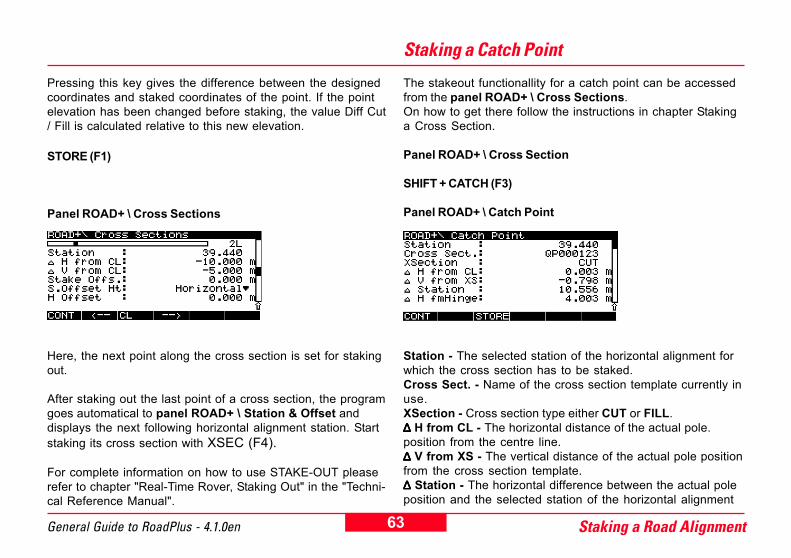
Here, the next point along the cross section is set for stakingout.
After staking out the last point of a cross section, the programgoes automatical to panel ROAD+ \ Station & Offset anddisplays the next following horizontal alignment station. Startstaking its cross section with XSEC (F4).
For complete information on how to use STAKE-OUT pleaserefer to chapter "Real-Time Rover, Staking Out" in the "Techni-cal Reference Manual".
Staking a Catch Point
The stakeout functionallity for a catch point can be accessedfrom the panel ROAD+ \ Cross Sections.On how to get there follow the instructions in chapter Stakinga Cross Section.
Panel ROAD+ \ Cross Section
SHIFT + CATCH (F3)
Panel ROAD+ \ Catch Point
Station - The selected station of the horizontal alignment forwhich the cross section has to be staked.Cross Sect. - Name of the cross section template currently inuse.XSection - Cross section type either CUT or FILL.∆∆∆∆∆ H from CL - The horizontal distance of the actual pole.position from the centre line.∆ ∆ ∆ ∆ ∆ V from XS - The vertical distance of the actual pole positionfrom the cross section template.∆∆∆∆∆ Station - The horizontal difference between the actual poleposition and the selected station of the horizontal alignment

64Staking a Road Alignment General Guide to RoadPlus - 4.1.0en
for which the cross section has to be staked.∆∆∆∆∆ H fmHinge - The horizontal distance of the actual poleposition from the hinge point.∆∆∆∆∆ V fmHinge - The vertical distance of the actual pole positionfrom the hinge point.Slope Dist - The slope distance of the actual pole positionfrom the hinge point. Once the catch point has been found,this is the slope distance between the catch point and thehinge point.Elevation - Height of the actual pole position.
According to the update rate, the individual values areupdated automatically. Note that the highest update rate inthis panel is 1 second even though the general update ratemight be set to a value < 1 second.
The catch point has been found when the ∆ ∆ ∆ ∆ ∆ V from XS and ∆∆∆∆∆Station are zero. Navigate to the correct point. Place theantenna pole at the location. Be sure that the antenna islevelled.
∆ H from CL
∆ V from XS
∆ H fm Hinge
∆ V fm HingeHinge Point
Catch Point
∆ V from XS
∆ H from CL
Catch Point
Hinge Point
∆ V fm Hinge
0 + 39.448
0 + 50.000
Catch Point
when moving exactly along the crosssection line then ∆ Station = 0
∆ Station
∆ H fm Hinge
Catch Point
Hinge Point
Reference Point
Slope Dist CP
Slope Dist RP
Catch Point
Hinge Point
Reference Point
Slope Dist CP
Slope Dist RP
65General Guide to RoadPlus - 4.1.0en Staking a Road Alignment
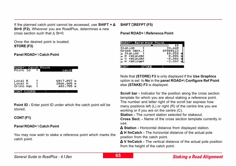
If the planned catch point cannot be accessed, use SHIFT + ∆ ∆ ∆ ∆ ∆St=0 (F2). Wherever you are RoadPlus, determines a newcross section such that ∆ St=0.
Once the desired point is located:STORE (F3)
Panel ROAD+ \ Catch Point
SHIFT + + + + + REFPT (F5)
Panel ROAD+ \ Reference Point
Point ID - Enter point ID under which the catch point will bestored.
CONT (F1)
Panel ROAD+ \ Catch Point
You may now wish to stake a reference point which marks thecatch point.
Note that (STORE) F3 is only displayed if the Use Graphicsoption is set to No in the panel ROAD+\ Configure Ref Pointelse (STAKE) F3 is displayed.
Scroll bar - Indicator for the position along the cross sectiontemplate for which you are about staking a reference point.The number and letter right of the scroll bar express howmany positions left (L) or right (R) of the centre line you areworking or if you are on the centre (C).Station - The current station selected for stakeout.Cross Sect. - Name of the cross section template currently inuse.∆∆∆∆∆ Station - Horizontal distance from displayed station.∆∆∆∆∆ H fmCatch - The horizontal distance of the actual poleposition from the catch point.∆∆∆∆∆ V fmCatch - The vertical distance of the actual pole positionfrom the height of the catch point.

66Staking a Road Alignment General Guide to RoadPlus - 4.1.0en
∆∆∆∆∆ H fmHinge - The horizontal distance of the actual poleposition from the hinge point.∆∆∆∆∆ V fmHinge - The vertical distance of the actual poleposition from the height of the hinge point.∆∆∆∆∆ H from CL - The vertical distance of the actual pole positionfrom the centre line.∆ ∆ ∆ ∆ ∆ V from CL - The vertical distance of the actual pole positionfrom the height of the centre line.∆∆∆∆∆ V fmSlope - The vertical distance of the actual pole positionabove the slope. Only available once the reference point hasbeen stored.Slope - Slope value.Slope Dist - The slope distance of the actual pole positionfrom the hinge point. Once the reference point has beenfound, this is the slope distance between the reference pointand the hinge point.Elevation - Height of the actual pole position.
According to the update rate, the individual values areupdated automatically. Note that the highest update rate inthis panel is 1 second even though the general update ratemight be set to a value < 1 second.
Either navigate to a point which is suitable as reference pointor until ∆ H and ∆ V from catch / hinge / centre line / slopeshow required values. Place the antenna pole at the location.Be sure that the antenna is levelled. If you decide not to stakeand store the reference point, press CONT (F1). It takes you
back to the panel ROAD+ \ Catch Point.
Otherwise: (if the Use Graphics option is set to No in thepanel ROAD+\ Configure Ref Point)
STORE (F3)
Panel ROAD+ \ Reference Point
Point ID - Enter name under which the reference point will bestored.
CONT (F1) returns to the panel ROAD+\ Reference Point
Or: (if the Use Graphics option is set to Yes in the panelROAD+\ Configure Ref Point)
67General Guide to RoadPlus - 4.1.0en Staking a Road Alignment
STAKE (F3)You will be taken to the Stakeout graphics screen.
Panel STAKE-OUT \ xxxwhereas xxx is the name for the file stake point as defined instake out setting.
Orient - Select a method of orientation as reference direction.
The next line shows the station of the horizontal alignment towhich the cross section is assigned. The number and letterin brackets to the right express how many positions left (L) orright (R) of the cross section's centre line you are working or ifyou are on the centre (C). A * next to it indicates that this pointhas been staked already.
Out / In and Right / Left - This is the range to the selectedpoint and is updated as the antenna pole is moved.Cut / Fill - Indicates the cut / fill to the surface. If the pointelevation in the previous panel has been changed, the valuefor cut applies to this new elevation.
Once in the Stakeout graphics screen navigate to the correctpoint as normal. Place the antenna pole at the location. Besure that the antenna is levelled. Once the desired point islocated:
OCUPY (F1)
Panel STAKE-OUT \ Occupy Point
The current Point ID may be accepted or changed.
3D Quality - Observe the position quality indicator. Datashould not be recorded until you are satisfied with this value.When you are satisfied:STOP (F1)
68Staking a Road Alignment General Guide to RoadPlus - 4.1.0en
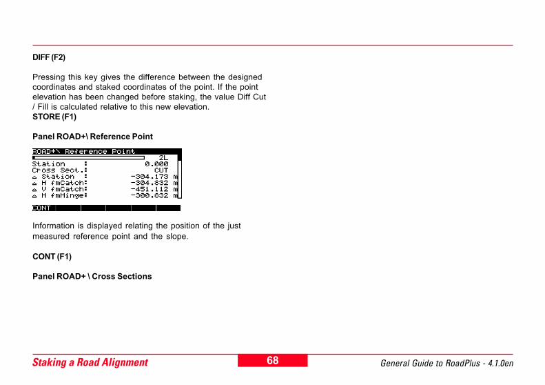
DIFF (F2)
Pressing this key gives the difference between the designedcoordinates and staked coordinates of the point. If the pointelevation has been changed before staking, the value Diff Cut/ Fill is calculated relative to this new elevation.STORE (F1)
Panel ROAD+\ Reference Point
Information is displayed relating the position of the justmeasured reference point and the slope.
CONT (F1)
Panel ROAD+ \ Cross Sections
69General Guide to RoadPlus - 4.1.0en Glossary
GlossaryA
Parameter A of a clothoïde. Defined as A2 = R x L (A - para-meter, R - radius, L - length of portion of curve).
Alignment
A curvilinear line describing the plan or profile view of a project.Horizontal and Vertical Alignments exist.
Backward Station Equation
See overlap equation
Batter
Slope
Carriage Way
The final driving path. Also called roadway or travel way.
Catch Point
A point marking the intersection between the design surfaceand the original ground.
Centre Line
The plan view alignment, also called Horizontal Alignment.
Chainage
The cumultative distance along the horizontal alignment,frequently but not always starting at zero. Also called station.
Clothoïde
A horizontal curve with constantly linear increasing curving.Defined by A2 = R x L (A - parameter, R - radius, L - length ofportion of curve).
Cross Section
A profile view of a project at a particular station.
Curve
A horizontal curve of constant radius, e.g. a portion of a circle.
70 General Guide to RoadPlus - 4.1.0enGlossary
Curve In
A portion of a clothoïde. Spiral transition from larger to smallerradius curve (R1 > R2, parameter A).
Curve Out
A portion of a clothoïde. Spiral transition from smaller to largerradius curve (R1 < R2, parameter A).
Curvilinear
A line consisting of any combination of tangents, curves and /or spirals for the horizontal or for the vertical of tangents,curves and / or parabolas.
Cut Slope
The surface of the project in areas of excavation with thedesign surface below original ground.
Design Surface
The intended shape of the completed project.
Equation
Required for a point on the horizontal alignment where thestationing is discontinuous. Gap equations and overlapequations are distinguished.
Fill Slope
The surface of the project in areas of fill with the designsurface above original ground.
Finished Road Level
The level to which the final road is build to.
Forward Station Equation
See gap equation
Gap Equation
A type of station equation handling gaps in the stationing afterremoving a constituing element and stationing has not beenre-computed.

71General Guide to RoadPlus - 4.1.0en Glossary
Grade
Rate of change in elevation of the vertical alignment.
Ground Surface
See original ground
Hinge Point
The point on the cross section marking the beginning of thecut or fill slope.
Horizontal Alignment
The plan view alignment, also called centreline.
Long Profile
The profile alignment, also called vertical alignment.
Offset
The horizontal or vertical distance from a point to an alignmentor cross section.
Offset Point
See reference point
Original Ground
The undisturbed surface before project construction is startedas well as the actual shape of the project at the current stageof construction; also called original surface or ground surface.
Original Surface
See original ground
Overlap Equation
A type of station equation handling overlaps in the stationingafter inserting a constituing element and stationing has notbeen re-computed.
P
Parameter P. This is the reciprocal of the rate of change ofgrade in the vertical curve. Three formulas for the calculation ofP exist (see chapter Vertical Alignment).
72 General Guide to RoadPlus - 4.1.0enGlossary
Slope
The slope is next to the verge. It links the road level with theoriginal ground. Its slope ratio is usually higher than the one ofthe verge. For a fill, the slope direction corresponds to the oneof the verge. For a cut, it is the opposite direction.
Spiral
A gradual horizontal transition from a tangent to a curve or twocurves of different radii; optional for roads, required forrailroads.
Spiral In
A gradual horizontal spiral transition from a tangent to a curve(R1 = ∞, R2 = n, parameter A).
Spiral Out
A gradual horizontal spiral transition from a curve to a tangent(R1 = n, R2 = ∞, parameter A).
Station
The cumultative distance along the horizontal alignment,frequently but not always starting at zero. Also called chainage.
Parabola
A parabolic arc. Exists only on vertical alignments.
Profile
See cross section
Reference Point
A second point often marked nearby the catch point or otherpoint of interest since the catch point is often gone after thefirst earth movements. The stake is typically marked with theinformation that allows the user to replace the point of interestand re-create the slope information. Also known as the offsetpoint.
Roadway
See carriage way
Shoulder
See verge
73General Guide to RoadPlus - 4.1.0en Glossary
Station Ahead
The stationing to be applied going forward along the alignmentfrom the equation.
Station Back
The stationing to be applied going backwards along thealignment from the equation.
Station Equation
It defines adjustments for the Horizontal Alignment File whenconsituing elements have been added / removed resulting in agap or overlap in the stationing without re-computing station-ing.
Superelevation
Modification of the normal pavement cross slope. Intended toincrease comfort and safety at speed.
Verge
Next to the carriage way, the part of the road with usually aslightly higher slope ratio. Also called shoulder.
Tangent
A straight line connecting two position points (XY) or heightpoints (Z). It touches a circle, curve or spiral in one point and isperpendicular to the radius of the circle, curve or spiral in thispoint.
Top (of Bank)
A catch point marking the catch of a cut slope.
Toe (of Bank/Slope)
A catch point marking the catch of a fill slope.
Travel Way
See carriage way
Vertical Alignment
The profile alignment, also called long profile.
Widening
Increase / decrease of road width with change in number oflanes.

74 General Guide to RoadPlus - 4.1.0enGlossary
Index
AA 11, 67Alignment 67
BBackward Station Equation 67Batter 67
CCarriage Way 45, 46, 47, 67Catch Point 45, 46, 47, 67Centre Line 67Chainage 67Clothoïde 67Conversion Programs 41Cross Section 15, 67Cross Section (Template) File 22, 31Cross Section Assignment 17Cross Section Assignment File 22, 35Curve 10, 13, 67Curve In 11, 68Curve Out 11, 68Curvilinear 68Cut 45Cut Slope 68
DDesign Elements 8Design Surface 68
EEquation 68
FFill 46Fill Slope 68Finished Road Level 45, 46, 47, 68Forward Station Equation 68
GGap Equation 21, 68Grade 69Ground Surface 69
HHinge Point 45, 46, 47, 69Horizontal Alignment 9, 69Horizontal Alignment File 22, 23
LLong Profile 69

75General Guide to RoadPlus - 4.1.0en Glossary
OOffset 69Offset Catch Point 47Offset Point 69Original Ground 45, 46, 47, 69Original Surface 69Overlap Equation 21, 69
PP 14, 69Parabola 13, 70Profile 70
RReference Point 70RoadEd 41Roadway 70
SShoulder 47, 70Sipral In 10Sipral Out 10Slope 45, 46, 47, 70Slope Ratio 16Spiral 70Spiral In 70Spiral Out 70Station 70
Station Ahead 21, 71Station Back 21, 71Station Equation 20, 71Station Equation File 22, 38Superelevation 19, 71
TTangent 10, 13, 71Toe of Bank 47, 71Top of Bank 47, 71Travel Way 71
VVerge 45, 46, 47, 71Vertical Alignment 12, 71Vertical Alignment File 22, 27
WWidening 18, 71
Leica Geosystems AG, Heerbrugg,Switzerland, has been certified asbeing equipped with a quality systemwhich meets the International Stan-dards of Quality Management andQuality Systems (ISO standard 9001)and Environmental ManagementSystems (ISO standard 14001).
Total Quality Management-Our commitment to total customersatisfaction
Ask your local Leica agent for moreinformation about our TQM program
Leica Geosystems AGCH-9435 Heerbrugg
(Switzerland)Phone +41 71 727 31 31
Fax +41 71 727 46 73www.leica-geosystems.com
Printed in Switzerland - Copyright LeicaGeosystems AG, Heerbrugg, Switzerland 2003Original text
725974 - 4.1.0en