Embed Size (px)
Citation preview

AIS-060
AUTOMOTIVE INDUSTRY STANDARDS
General Guidelines on
Control Cables for Automobiles
PRINTED BY
THE AUTOMOTIVE RESEARCH ASSOCIATION OF INDIA P.B. NO. 832, PUNE 411 004
ON BEHALF OF
AUTOMOTIVE INDUSTRY STANDARDS COMMITTEE
UNDER CENTRAL MOTOR VEHICLE RULES – TECHNICAL STANDING COMMITTEE
SET-UP BY
MINISTRY OF ROAD TRANSPORT & HIGHWAYS (DEPARTMENT OF ROAD TRANSPORT & HIGHWAYS)
GOVERNMENT OF INDIA
July 2010 I
AIS-060
Status chart of the Standard to be used by the purchaser
for updating the record Sr. No.
Corr-igenda
Amend- ment
Revision Date Remark Misc.
General remarks:
II

AIS-060
INTRODUCTION The Government of India felt the need for a permanent agency to expedite the publication of standards and development of test facilities in parallel when the work on the preparation of the standards is going on, as the development of improved safety critical parts can be undertaken only after the publication of the standard and commissioning of test facilities. To this end, the erstwhile Ministry of Surface Transport (MOST) has constituted a permanent Automotive Industry Standard Committee (AISC) vide order No. RT-11028/11/97-MVL dated September 15, 1997. The standards prepared by AISC will be approved by the permanent CMVR Technical Standing Committee (CTSC). After approval, the Automotive Research Association of India, (ARAI), Pune, being the Secretariat of the AIS Committee, has published this standard. For better dissemination of this information ARAI may publish this document on their Web site. This guideline standard on control cables used in automobiles covers construction, materials, shape, dimensions, testing procedure and requirements. While preparing this standard considerable assistance is derived from following standards: i) JASO F 903 -75: Control Cables for Automobiles ii) JASO T 001- 97: Control Cables for Motorcycles The Automotive Industry Standards Committee (AISC) responsible for preparation of this standard is given in Annexure: 31
III
AIS-060
General Guidelines on Control Cables for Automobiles
1. SCOPE This standard covers the requirements of control cables (hereinafter
referred to as “cables”) mainly used for the purpose of tension control (pulling) in automobiles in all types of four and two wheelers including mopeds, motorbikes and motorcycles.
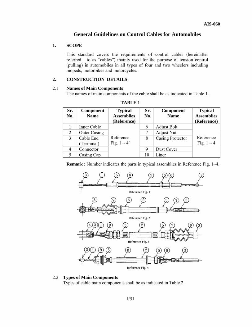
2. CONSTRUCTION DETAILS 2.1 Names of Main Components The names of main components of the cable shall be as indicated in Table 1.
TABLE 1
Sr. No.
Component Name
Typical Assemblies (Reference)
Sr. No.
Component Name
Typical Assemblies (Reference)
1 Inner Cable Reference Fig. 1 ~ 4`
6 Adjust Bolt
Reference Fig. 1 ~ 4
2 Outer Casing 7 Adjust Nut 3 Cable End
(Terminal) 8 Casing Protector
4 Connector 9 Dust Cover 5 Casing Cap 10 Liner
Remark : Number indicates the parts in typical assemblies in Reference Fig. 1~4.
2.2 Types of Main Components
Types of cable main components shall be as indicated in Table 2.
1/51
Reference Fig. 1
Reference Fig. 2
Reference Fig. 3
Reference Fig. 4

AIS-060
TABLE 2
Sr. No.
Component Name Type Remarks Applicable Annexure
1. Inner Cable Stranded Cable
Single Strand
Has the highest breaking strength / shear load among cables of the same outside diameter.
Annexure 1
Multiple Strands
Has the highest flexibility / bending property. Among cables of the same outside diameter.
Annexure 2
Coated Wire Has high operating efficiency, corrosion resistance.
Annexure 3
Single Wire ----- Annexure 4 2. Outer Casing With liner Has a high operational efficiency Annexure 5
Without liner (Plastic Tube)
Used for the inner coat type Annexure 6
Twin wire conduit Conduit with twin wire 3. Cable End Type A Type A1 Drum Shape (Soldered) Annexure 7
Type A2 Drum Shape (Cast)Type B Type B1 Umbrella Shape (Caulked) Annexure 8
Type B2 Umbrella Shape (Cast) Type C
Type C1
Round Tube Shape (Soldered) Annexure 9
Type C2 Round Tube Shape (Caulked or Soldered)
Type C3 Square Tube Shape (Caulked)Type C4 Ball Shape (Caulked, Soldered or
Cast) Type D
Type D1 Screw Type (Caulked part same as rolling diameter)
Annexure 10
Type D2 Screw Type (Caulked part larger than rolling diameter)
Type E Threaded Type Annexure 11 4. Connector Type A Type A1 Clevis Type (Constant opening) Annexure 12
Type A2 Clevis Type (Opening becomes smaller)
Type B ------ Annexure 13 5. Casing Cap Type A Type A1 Tubular type (Made by press) Annexure 14
Type A2 Tubular type (Made by machining) Type B Type B1 Tubular type (with flange) Annexure 15
Type B2 Tubular type (with flange and dust cover groove)
Type C Type C1 Screw type Annexure 16 Type C2 Screw type (with hexagon part)
Type D
Type D1 Clamp stoppage type Annexure 17
Type D2 Clamp stoppage type (E ring stoppage type)
Annexure 18
Type D3 Clamp type Annexure 19 Type D4 Forced insertion type Annexure 20
6. Adjust Bolt Type A For stacking Annexure 21 7. Adjust Nut Type A For stacking box nut Annexure 22
2/51

AIS-060
Sr. No.
Component Name Type Remarks Applicable Annexure
8. Round joint Type A Type A1 For rotary stacking
(without flange) Annexure 23
Type A2 For rotary stacking (with flange)
Annexure 24
Type B
Type B1 For direct stacking Annexure 25 Type B2 For direct stacking
(threaded)Annexure 26
Type B3 For direct stacking (non-threaded)
Annexure 27
9. Casing Protector ----- ----- Annexure 28 10. Dust Cover Type A1 Boot type Annexure 29
Type A2 Boot type Type B ----- Annexure 30
3. MAIN COMPONENT MATERIALS AND SURFACE TREATMENTS
Materials and surface treatment of the main components shall as a general rule, conform to Table 3.
TABLE 3
Sr. No.
Component Name
Type Material Surface Treatment
1. Inner Cable Stranded Cable Ropes and strands to confirm • IS: 5836-1977 Inner wire ropes
for automobile control cables (First Revision)
• IS: 6594-1977 Technical supply conditions for steel wire ropes and strands (First Revision)
• IS: 1835-1976 Round steel wire for ropes (Third Revision)
JIS G 3506, SWRH 57~82
Correspond to JIS G 3535, 4.8
JIS G 4308, SUS304-WR or SUS302-WR
-----
Coated Wire Synthetic resin (Coating material) ----- Single Wire JIS G 3521, SW Correspond to
JIS G 3535, 4.82. Outer Casing ----- Patented and cold-drawn spring steel
wire of Grade 1 of IS:4454 (Part 1) – 1975 “Steel wires for cold formed springs: Part 1 Patented and cold drawn steel wires – unalloyed (First revision)” JIS G 3506, SWRH 57 ~ 82
Correspond to JIS G 3535, 4.8
Outer casing insulation stable fibre yarn with weatherproof lacquering or PVC as per agreement between the purchaser and the manufacturer. Synthetic resin, black
-----
Plastic Tube Synthetic resin -----
3/51

AIS-060
Sr. No.
Component Name Type
Material Surface Treatment
3. Cable End (terminals)
Type A1 The material shall conform to IS: 226-1975 “Structural steel (standard quality) (Fifth Revision). If of brass, it shall conform to IS: 4170-1967 “Brass rods for general engineering purposes” or IS: 4413-1967 “Brass wires for general engineering purposes”. JIS H 3422, BsBM
---
--- Type A2 JIS H 5301, ZDC Type B1 JIS G 4051, S15C ~ S35C JIS D 0201, MFZn5-B
or MFZn5-C ---
Type B2 JIS H 5301, ZDC
Type C1 JIS H 3422, BsBM --- JIS D 0201, MFZn5-B or MFZn5-C
--- JIS D 0201, MFZn5-B or MFZn5-C
Type C2 JIS G 4051, S15C~S35C JIS H 5301, ZDC
Type C3 JIS G 4051, S15C~S35C Type C4 JIS G 4051, S15C~S35C
JIS H 3422, BsBM --- JIS H 5301, ZDC ---
Type D1 Type D2
JIS G 4051, S15C~S35C JIS D 0201, MFZn5-B or MFZn5-C
4. Connector Type A1 Type A2 Type B
JIS G 3131, SPHC JIS D 0201, MFZn5-B or MFZn5-C JIS G 3141, SPCC
5. Casing Cap
(Bush) Type A1 Steel conforming to IS: 226-1975.
JIS H 3201, BsP ---
JIS D 0201, MFZn5-B or MFZn5-C
---
JIS G 3141, SPCC Type A2
JIS H 3422, BsBM JIS G 3101, SS or free cutting steel JIS D 0201, MFZn5-B
or MFZn5-C Type B1 JIS H 3422, BsBM ---
JIS D 0201, MFZn5-B or MFZn5-C
---
JIS G 3101, SS or free cutting steel Type B2 JIS H 3422, BsBM
JIS G 3101, SS or free cutting steel JIS D 0201, MFZn5-B or MFZn5-C
JIS H 5301, ZDC --- Type C1 JIS H 3422, BsBM ---
JIS D 0201, MFZn5-B or MFZn5-C
Type C2 JIS G 3101, SS or free cutting steel
Type D1 JIS H 5301, ZDC --- Type D2 JIS G 3101, SS or free cutting steel Type D3 JIS D 0201, MFZn5-B
or MFZn5-C Type D4 JIS G 3101, SS or free cutting steel 6. Adjust Bolt ----- JIS G 3101, SS or free cutting steel JIS D 0201, MFZn5-B
or MFZn5-C 7. Adjust Nut ----- JIS G 3101, SS or free cutting steel JIS D 0201, MFZn5-B
or MFZn5-C 8. Casing Protector ----- Synthetic resin or rubber, black --- 9. Dust Cover Type A1, A2
Type B Synthetic resin or rubber, black ---
Note: In case of material and construction not available as per Table 3, the material and construction shall be as per the agreement between the cable supplier and the customer.
4/51
AIS-060 4. SHAPES AND DIMENSIONS OF MAIN COMPONENTS The shapes and dimensions of the cable main components shall be as
indicated in Annexures 1 ~ 30. 5. QUALITY 5.1 Appearance
(1) Components shall be free from bending, cracks, corrosion, turnback, burrs, and other defects injurious to use.
(2) Surface treatment of components shall satisfy the requirements in 3.
(3) Cable shall have proper lubricant applied on the inner cable of filled in the outer casing. The variety of lubricant used shall be as agreed between the supplier and receiver.
5.2 Dimensions and Tolerances
(1) Dimensions and tolerances of components shall satisfy the requirements in Annexures 1 ~ 30, except that in the caulked type cable ends, the inner surface shall, as a rule, be chamfered before hand to prevent decrease in strength.
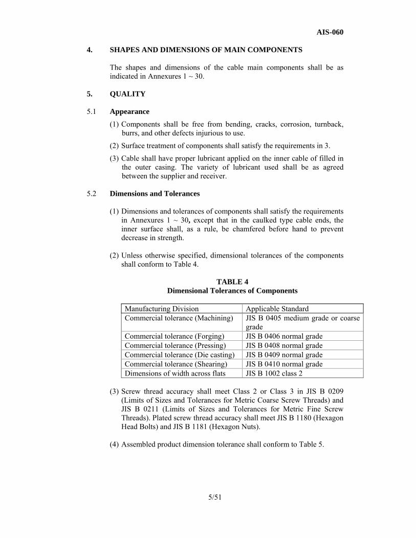
(2) Unless otherwise specified, dimensional tolerances of the components
shall conform to Table 4.
TABLE 4 Dimensional Tolerances of Components
Manufacturing Division Applicable Standard Commercial tolerance (Machining) JIS B 0405 medium grade or coarse
grade Commercial tolerance (Forging) JIS B 0406 normal grade Commercial tolerance (Pressing) JIS B 0408 normal grade Commercial tolerance (Die casting) JIS B 0409 normal grade Commercial tolerance (Shearing) JIS B 0410 normal grade Dimensions of width across flats JIS B 1002 class 2
(3) Screw thread accuracy shall meet Class 2 or Class 3 in JIS B 0209
(Limits of Sizes and Tolerances for Metric Coarse Screw Threads) and JIS B 0211 (Limits of Sizes and Tolerances for Metric Fine Screw Threads). Plated screw thread accuracy shall meet JIS B 1180 (Hexagon Head Bolts) and JIS B 1181 (Hexagon Nuts).
(4) Assembled product dimension tolerance shall conform to Table 5.
5/51

AIS-060
TABLE 5-1 When Without Dust Cover
Unit: mm
l a + b (Travel length) Nominal Tolerance Tolerance
100 and under Over 100 500 and under ± 2 ± 1.5 ± 2.0 Over 500 to 1000 including ± 3 ± 2.0 ± 2.5 Over 1000 to 2000 including ± 4 ± 2.5 ± 3.0 Over 2000 to 3000 including ± 5
TABLE 5-2 When with Dust Cover
Unit: mm
L and l Nominal Tolerance
500 and under ± 2 Over 500 to 1000 including ± 3 Over 1000 to 2000 including ± 4 Over 2000 to 3000 including ± 5
5.3 Performance
(1) Cable shall operate smoothly in straight-line state.
(2) On the assembly parts, inner cable-shearing load, and cable end and casing cap pull off loads shall meet the requirements in Annexures 1, 4, 7, 8, 9, 10, 13, 14, 15, 16, 17, 18, 19 and 20.
(3) Cable shall comply with the purpose of application and satisfy the operating efficiency and other functions required in actual operation.
6. TESTING OF THE CABLES
The test procedure and acceptance norms for testing control cables listed below. a) Accelerator cable b) Parking brake cable c) Bonnet release cable d) Ventilation cable
6/51

AIS-060
e) Fuel lid opening cables. f) Choke cable g) Clutch cable h) Idling adjuster cable. i) Brake cable – Front & Rear
6.1 Tests
a) Bench performance tests b) Durability / Endurance test. c) Strength test d) Environmental aging test.
6.1.1 Bench Performance Tests Cable fitment shall be done on test bench with cable routing as described in
clause No. 6.1.2.1. No fouling of the cable with surrounding components shall be observed. The following are the performance tests, which can either be performed on a vehicle or on a test bench.
6.1.1.1 Operating Force Test In order to check the smoothness of the cable operation, operating force
shall be measured. This is to be measured on the test bench which simulates the test item cable e.g. force required to push the pedal for accelerator cable.
6.1.1.2 Efficiency Test Test procedure as per clause 6.1.3. 6.1.1.3 Load Efficiency Test: with cable installed as in actual vehicle
Sr. No.
Cable type Temperature at which efficiency to be checked
Load for the test
1 All cables in the test standard except clutch cable & accelerator cable
a) 80 º C b) -10 º C c) Ambient temp.
As agreed between the customer and supplier or drawing
2 Clutch cable & accelerator cable
d) 80 to 120 º C e) -35 to -40 º C f) Ambient temp.
specification.
6.1.2 Durability / Endurance Test.
The test procedure shall be as follows: (1) Performance measurement before durability test (2) Operational durability test (3) Performance measurement after durability test (4) Performance measurement may also be conducted during the durability test.
7/51

AIS-060
6.1.2.1 Setting of Cable for Durability Test
The cable shall be sent in the same way as specified in figure 5 & 6.
Fig. 6
Test set up for Durability Test at the End of Cable (when round joint is used)
6.1.2.2 Performance Measurement before Durability Test
Pull input side of the inner cable of assembly at the operating speed shown in Table 6. Apply the specified load to the output side, and then measure the load efficiency and stroke loss.
8/51
Fig. 5 Test set up for Durability test

AIS-060
TABLE 6
Specifications for Performance Measurement
Sr. No.
Type of cable Type application
Load Operating speed mm/sec
1 Front brake cable Force application and release.
540 N
10
2 Rear brake lever type 540 N 3 Rear brake foot type 780 N 4 Clutch 290 N 5 Throttle 100 N 6 Hood release cable,
Tailgate cable, Fuel lid cable, Door latch cable.
50 N
The measurement of any items other than the load efficiency and stroke loss shall be in accordance with an agreement between the suppliers and users.
6.1.2.3 Operational Durability Test
Give the load and stroke repeatedly to the input side of cable so that the maximum load and stroke shown in Table 7 can be kept at the output side. The repetition times per minute and endurance times are also shown in Table 7.
TABLE 7 Specifications for Operational Durability Test
Sr. No.
Type of cable Specified load of output side
(N)
Stroke of output
side (mm)
Cycling rate
Total no. of cycles
Acceptance norm
1 Front cable 540 15 10 to 60 cycles/ minute
1,00,000 No failure of the cable throughout the test
2 Rear brake lever type 540 15 10 to 60 cycles/ minute
50,000 No failure of the cable throughout the test
3 Rear brake foot type 780 10 10 to 60 cycles/ minute
50,000 No failure of the cable throughout the test
4 Clutch 290 20 10 to 60 cycles/ minute
1,00,000 to 5,00,000
No failure of the cable throughout the test
5 Throttle 100 25 10 to 60 cycles/ minute
1,00,000 to 10,00,000
No failure of the cable throughout the test
6 Hood release cable, Tail gate cable, Fuel lid cable, Door latch cable.
50 20 10 to 60 cycles/ minute
5,000 to 20,000
No failure of the cable throughout the test
9/51
AIS-060 6.1.2.4 Performance Measurement after Durability Test This test shall be conducted by the same method as specified in
clause 6.1.2.2. Performance Measurement before Durability Test.
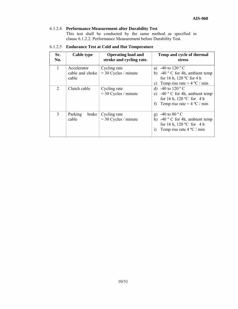
6.1.2.5 Endurance Test at Cold and Hot Temperature
Sr. No.
Cable type Operating load and stroke and cycling rate.
Temp and cycle of thermal stress
1 Accelerator cable and choke cable
Cycling rate = 30 Cycles / minute
a) -40 to 120 º C b) -40 º C for 4h, ambient temp
for 16 h, 120 ºC for 4 h c) Temp rise rate = 4 ºC / min
2 Clutch cable Cycling rate = 30 Cycles / minute
d) -40 to 120 º C e) -40 º C for 4h, ambient temp
for 16 h, 120 ºC for 4 h f) Temp rise rate = 4 ºC / min
3 Parking brake cable
Cycling rate = 30 Cycles / minute
g) -40 to 80 º C h) -40 º C for 4h, ambient temp
for 16 h, 120 ºC for 4 h i) Temp rise rate 4 ºC / min
10/51
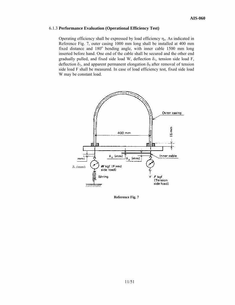
AIS-060 6.1.3 Performance Evaluation (Operational Efficiency Test)
Operating efficiency shall be expressed by load efficiency ηs. As indicated in Reference Fig. 7, outer casing 1000 mm long shall be installed at 400 mm fixed distance and 180o bending angle, with inner cable 1500 mm long inserted before hand. One end of the cable shall be secured and the other end gradually pulled, and fixed side load W, deflection δ1, tension side load F, deflection δ2, and apparent permanent elongation δ0 after removal of tension side load F shall be measured. In case of load efficiency test, fixed side load W may be constant load.
Reference Fig. 7
11/51
δ1 (mm)
AIS-060
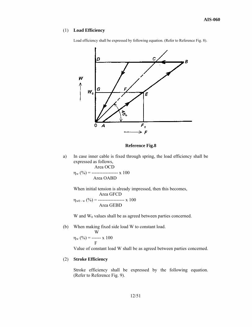
(1) Load Efficiency
Load efficiency shall be expressed by following equation. (Refer to Reference Fig. 8).
Reference Fig.8 a) In case inner cable is fixed through spring, the load efficiency shall be
expressed as follows, Area OCD
ηw (%) = ----------------- x 100 Area OABD
When initial tension is already impressed, then this becomes,
Area GFCD ηw0 - w (%) = ----------------- x 100
Area GEBD W and W0 values shall be as agreed between parties concerned.
(b) When making fixed side load W to constant load. W
ηw (%) = ------ x 100 F
Value of constant load W shall be as agreed between parties concerned.
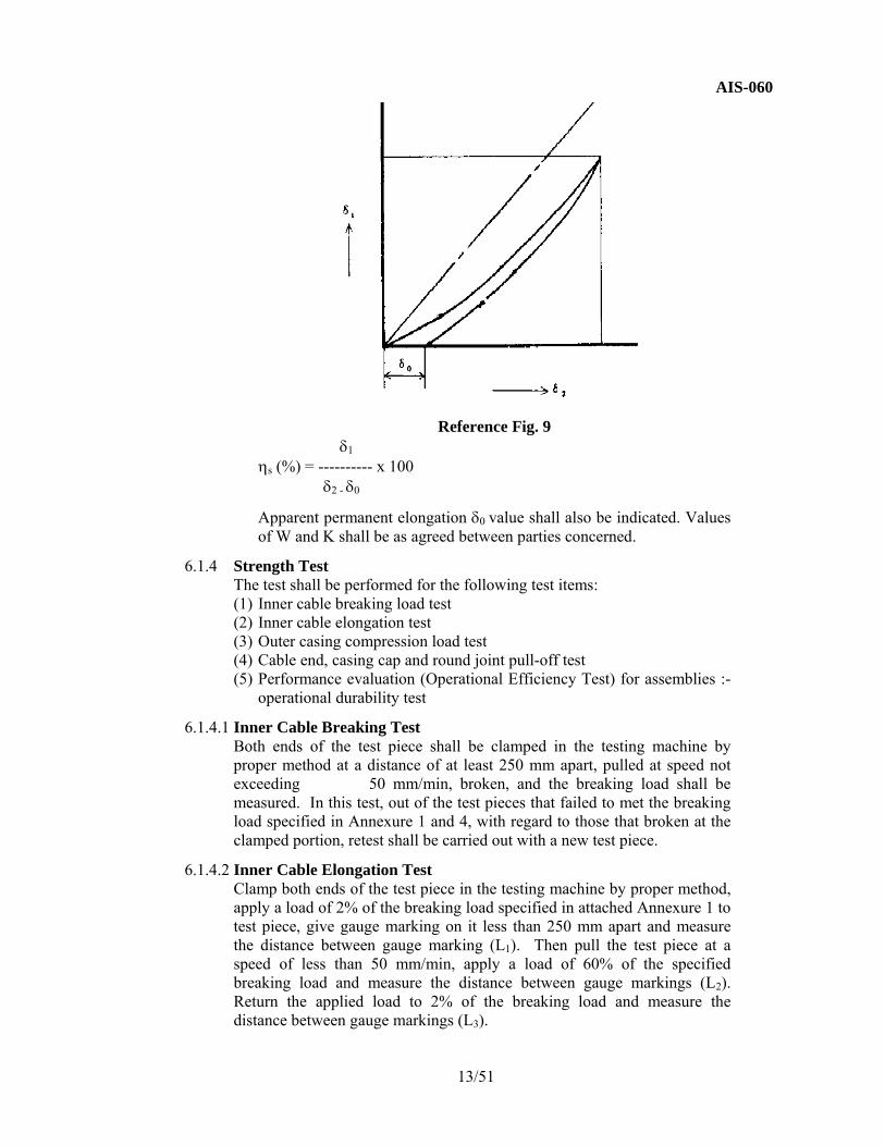
(2) Stroke Efficiency
Stroke efficiency shall be expressed by the following equation. (Refer to Reference Fig. 9).
12/51
AIS-060
Reference Fig. 9
δ1 ηs (%) = ---------- x 100
δ2 - δ0
Apparent permanent elongation δ0 value shall also be indicated. Values of W and K shall be as agreed between parties concerned.
6.1.4 Strength Test The test shall be performed for the following test items: (1) Inner cable breaking load test (2) Inner cable elongation test (3) Outer casing compression load test (4) Cable end, casing cap and round joint pull-off test (5) Performance evaluation (Operational Efficiency Test) for assemblies :-
operational durability test
6.1.4.1 Inner Cable Breaking Test Both ends of the test piece shall be clamped in the testing machine by proper method at a distance of at least 250 mm apart, pulled at speed not exceeding 50 mm/min, broken, and the breaking load shall be measured. In this test, out of the test pieces that failed to met the breaking load specified in Annexure 1 and 4, with regard to those that broken at the clamped portion, retest shall be carried out with a new test piece.
6.1.4.2 Inner Cable Elongation Test Clamp both ends of the test piece in the testing machine by proper method, apply a load of 2% of the breaking load specified in attached Annexure 1 to test piece, give gauge marking on it less than 250 mm apart and measure the distance between gauge marking (L1). Then pull the test piece at a speed of less than 50 mm/min, apply a load of 60% of the specified breaking load and measure the distance between gauge markings (L2). Return the applied load to 2% of the breaking load and measure the distance between gauge markings (L3).
13/51

AIS-060
Then total elongation percentage, permanent elongation percentage and elastic elongation percentage shall be expressed in the following formulae” L2-L1 C1 = -------- X 100 L1
L3-L1 Co = --------- X 100
L1 C2 = (C1-Co)
Where Co: Permanent Elongation percentage of inner cable (%) C1: Total Elongation percentage of inner cable (%) C2: Elastic Elongation percentage of inner cable (%)
6.1.4.3 Outer Casing Compression Load Test
Set 300 mm long test piece of outer casing on the test apparatus as shown in Fig. 10. Apply the compression load to the test piece at a speed of less than 20 mm/min until it is crushed, and then measure the compression load.
Fig. 10
Size of Guide Wire
Unit: mm Outside diameter of outer casing Φ5 Φ6 Φ7 Φ8 Φ9 Diameter of guide wire Φ1.8 Φ2.1 Φ2.6 Φ3.5 Φ4.0
14/51

AIS-060
6.1.4.4 Cable End, Casing Cap and Round Joint Pull-Off Test
Both the ends of a test piece shall be clamped on the testing machine in such a manner as to allow the pull load to be measured and in an appropriate way, respectively as shown in Fig. 11. Pull the test piece at a speed of less than 50 mm/min until the cable end, casing cap and round joint are separated and then measure the pull-off load. For the test piece which does not meet the pull-off load values specified in attached Annexure 7, 8, 9, 10, 13, 14, 15, 16, 17, 18, 19 and 20 and broke at any portions other than the cable end, casing cap or round joint, take a new test piece from the same cable and test it again.
6.1.5 Environmental Test Salt Spray Test Salt spray test shall be conducted for a duration given in Table 8 on complete cable assembly as per IS: 9000 (Part 11) for following duration. There shall not be visible red rust which will harm the performance.
TABLE 8 Test for Observation of red rust. Inner cable 48 hrs Outer cable 24 hrs
7. INSPECTION
7.1 Inspection Items
Cable inspection items shall be as follows : (1) Material inspection (2) Appearance inspection (3) Dimension inspection (4) Performance inspection
7.1.1 Material Inspection
Material shall conform to the requirements in 3.
7.1.2 Appearance Inspection
Appearance shall conform to requirements in 5.1.
7.1.3 Dimension Inspection
Dimensions of components and assemblies shall conform to the requirements in 5.2.
15/51
Fig. 11
AIS-060
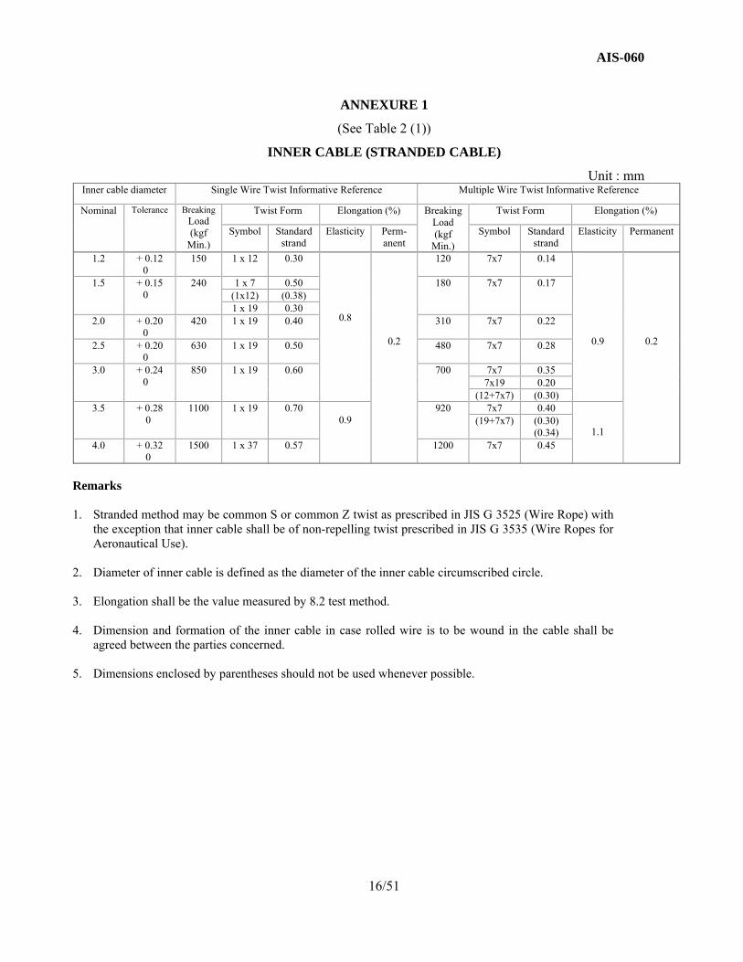
ANNEXURE 1
(See Table 2 (1))
INNER CABLE (STRANDED CABLE)
Unit : mm Inner cable diameter Single Wire Twist Informative Reference Multiple Wire Twist Informative Reference
Nominal Tolerance Breaking Load (kgf
Min.)
Twist Form Elongation (%) Breaking Load (kgf
Min.)
Twist Form Elongation (%)
Symbol Standard strand
Elasticity Perm-anent
Symbol Standard strand
Elasticity Permanent
1.2 + 0.12 0
150 1 x 12 0.30
0.8
0.2
120 7x7 0.14
0.9
0.2
1.5 + 0.15 0
240 1 x 7 0.50 180 7x7 0.17 (1x12) (0.38) 1 x 19 0.30
2.0 + 0.20 0
420 1 x 19 0.40 310 7x7 0.22
2.5 + 0.20 0
630 1 x 19 0.50 480 7x7 0.28
3.0 + 0.24 0
850 1 x 19 0.60 700 7x7 0.35 7x19 0.20
(12+7x7) (0.30) 3.5 + 0.28
0 1100 1 x 19 0.70
0.9 920 7x7 0.40
1.1
(19+7x7) (0.30) (0.34)
4.0 + 0.32 0
1500 1 x 37 0.57 1200 7x7 0.45
Remarks 1. Stranded method may be common S or common Z twist as prescribed in JIS G 3525 (Wire Rope) with
the exception that inner cable shall be of non-repelling twist prescribed in JIS G 3535 (Wire Ropes for Aeronautical Use).
2. Diameter of inner cable is defined as the diameter of the inner cable circumscribed circle. 3. Elongation shall be the value measured by 8.2 test method. 4. Dimension and formation of the inner cable in case rolled wire is to be wound in the cable shall be
agreed between the parties concerned. 5. Dimensions enclosed by parentheses should not be used whenever possible.
16/51

AIS-060
ANNEXURE 2
(See Table 2 (1))
INNER CABLE SECTION AND FORMATION
17/51

AIS-060
ANNEXURE 3
(See Table 2 (1))
INNER CABLE (COATED)
Unit: mm Inner cable diameter (d) Coat Finish diameter (D)
Size Tolerance Min. wall thickness (t)
1.2 1.8
+ 0.2 - 0.1
0.15 1.5 2.1 2.0 2.6 2.5 3.1 3.0 3.8
0.2 3.5 4.3 4.0 4.8
Remark : Inner cable (strand) used in inner cable (coated) shall conform to main Text
Annexure 1 and 2.
ANNEXURE 4
(See Table 2 (1))
INNER CABLE (SINGLE WIRE)
Unit: mm Inner cable diameter
Nominal Tolerance Breaking Load (kgf)
1.2 ± 0.05
As prescribed in JIS G 3521 1.4
1.6
18/51

AIS-060
ANNEXURE 5
(See Table 2 (2))
OUTER CASING
Unit: mm Applicable Inner Cable
D D0 d1 Reference
Uncoated Diameter
Coated finish diameter
Size Tolerance Standard strand
Diameter
Min. cover thickness
1.2 --- 5
2.4
± 0.2
3.6
1.0 1.2
0.4 1.4 ---
1.5 1.8 1.6 --- 1.5 1.8 6
2.9 4.7 1.6
1.7 0.4
2.0 2.1 2.5 2.6 7 3.8 5.6 1.6
1.7 0.4
3.0
3.1
7 3.8 5.6 1.6 1.7
0.4
8 4.3 6.1 1.6 1.7
0.6
9 4.8 7.2 1.8 2.0
10 4.8 7.2 1.8 2.0
0.6
3.5
3.8
9 4.8 7.2 1.8 2.0
0.6
10 4.8 7.2 1.8 2.0
0.6
10 5.2 8.1 2.2 0.8 4.3 12 5.4 8.5 2.6 1.1 4.8 12 5.9 9.0 2.6 1.1 13 6.2 9.8 3.0 1.1
Remarks 1. Outer casing winding direction may be either S twist or Z twist. 2. Outer casing end surfaces shall be provided with inner chamfer. 3. Standard strand diameter is defined as round wire diameter prior to forming into flat
wire.
19/51
AIS-060
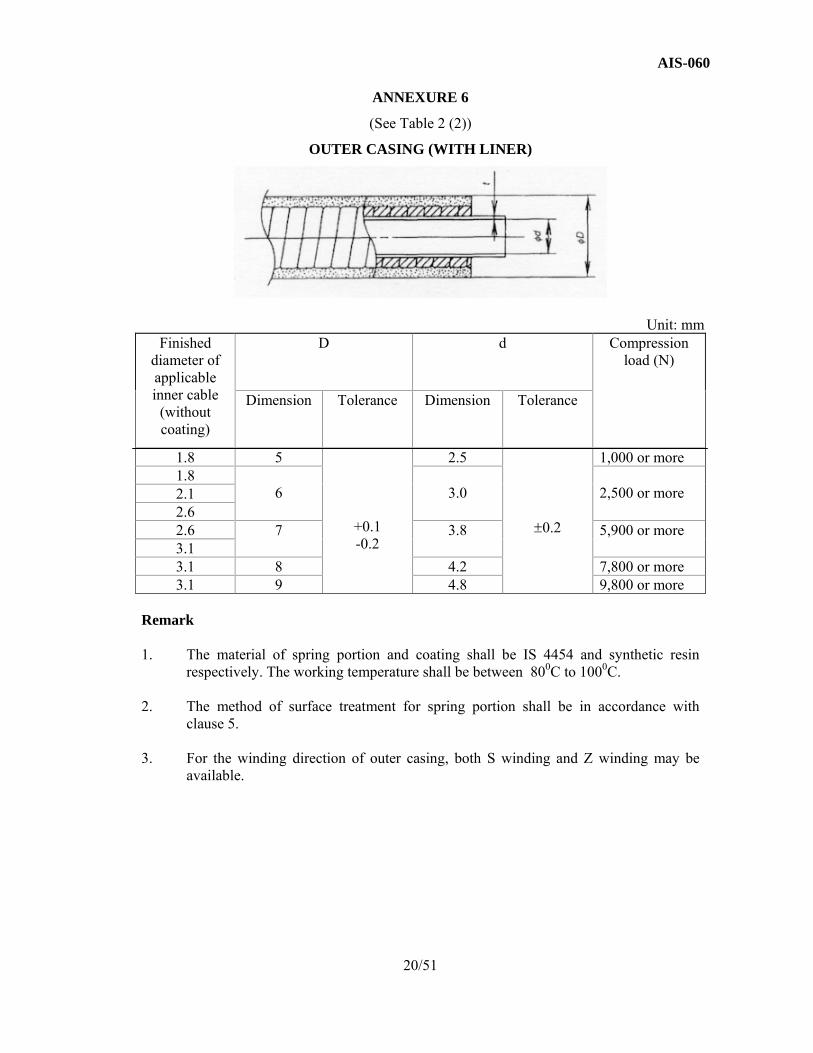
ANNEXURE 6
(See Table 2 (2))
OUTER CASING (WITH LINER)
Unit: mm Finished
diameter of applicable inner cable
(without coating)
D d Compression load (N)
Dimension Tolerance Dimension Tolerance
1.8 5
+0.1 -0.2
2.5
±0.2
1,000 or more 1.8
6
3.0
2,500 or more 2.1
2.6 2.6 7 3.8 5,900 or more 3.1 3.1 8 4.2 7,800 or more 3.1 9 4.8 9,800 or more
Remark
1. The material of spring portion and coating shall be IS 4454 and synthetic resin
respectively. The working temperature shall be between 800C to 1000C.
2. The method of surface treatment for spring portion shall be in accordance with clause 5.
3. For the winding direction of outer casing, both S winding and Z winding may be
available.
20/51

AIS-060
ANNEXURE 7
(See Table 2 (3))
CABLE END TYPE A
Unit: mm Applicable inner cable diameter
Pull off load (kgf Min.) D Size Tolerance
L Size Tolerance
1.2 70 5
± 0.15
8
± 0.2
6 8 10
1.5
100 5 8 10 6 8 10 12 8 10 12
2.0 180 6 8 10 12 8 10
2.5 280 8 10 10 10
3.0 420 8 10 12 (14) 10 10 12 (14)
Remarks 1. Pull off loads in Table above are applicable to both soldered and cast types.
2. Dimensions enclosed by parentheses shall not be used as far possible.
3. In case of establishing pull off load exceeding the value in the Table, the value shall be as agreed between the persons concerned.
21/51

AIS-060
ANNEXURE 8
(See Table 2 (3))
CABLE END TYPE B
Unit : mm Type Inner cable
φ x pull off load
(kgf Min.)
D L H
d1 L (Reference
Min.)
D2 (Reference)
Size Tolerance Size Tolerance Size Tolerance
Type B1
3.0 x 420 3.5 x 550
6.1
+ 0.2 0
25
± 1.5
6
± 0.2
7
7
14
7 30 5
6
8.1 30 5 8
8 (35) (5) (8) (20) (16)
4.0 x 720 8.1 30 8 8 8 16 Type B2
3.0x 420 3.5 x 550
6.1 25 6 6 ---
14 7 7
4.0 x 720 8.1 30 8 8 --- 16
Remarks 1. Type B1 caulking method shall, as a rule, be square caulking.
2. In case of heavy load, pull off load exceeding the value specified in the above Table may
be established upon agreement between the parties concerned and limited to Type B1.
3. Dimensions enclosed by parentheses shall not be used so far as possible.
22/51

AIS-060
ANNEXURE 9
(See Table 2 (3))
CABLE END TYPE C
Unit: mm Inner cable Dia-
meter
Pull off
load (kgf, Min.)
Type C1
Type C2
Type C3
Type C4
D L D L Material
Dia-meter
Dia-meter (max.)
D (Reference)
L D d (max)
Size Tolerance
Size Tolerance Size Tolerance Size Toler-ance
Refe-rence
Toler-ance
1.5 60 3
± 0.2
4 4
± 0.5
4
± 1
5 5.5 4.0
± 0.5
6
± 1
8 5 2.0 180 6 6 6 8 5 5.5 4.0 8 8 5 2.5 280 --- --- 7 10 6 6.5 5.0 10 8 5
7 7.5 5.5 3.0 420 ---
---
7 10 7 7.5 5.5 12 8 5 8 10 10 12 8 8.5 6.5 10
3.5 550 ---
---
7 10 8 8.5 6.5 14 10 6 (7) (12) 8 12 9 9.5 7.5 12 10 12
(10) (14) 4.0 720 --- --- 8 14 8 8.5 6.5 14 10 6
10 (9) (9.5) (7.5) (14)
Remarks
1. In case of heavy load, pull off load exceeding the value specified in above Table may be specified upon agreement between parties concerned. In such case, L may be lengthened if found necessary.
2. Dimensions enclosed by parentheses shall not be used as far as possible.
23/51
AIS-060
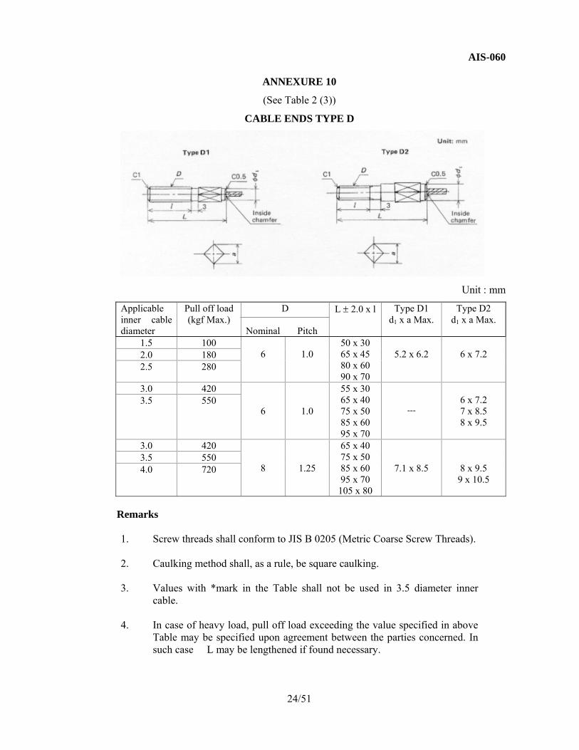
ANNEXURE 10
(See Table 2 (3))
CABLE ENDS TYPE D
Unit : mm
Applicable inner cable diameter
Pull off load (kgf Max.)
D Nominal Pitch
L ± 2.0 x l Type D1 d1 x a Max.
Type D2 d1 x a Max.
1.5 100 6
1.0
50 x 30 65 x 45 80 x 60 90 x 70
5.2 x 6.2
6 x 7.2 2.0 180
2.5 280
3.0 420 6
1.0
55 x 30 65 x 40 75 x 50 85 x 60 95 x 70
---
6 x 7.2 7 x 8.5 8 x 9.5
3.5 550
3.0 420 8
1.25
65 x 40 75 x 50 85 x 60 95 x 70 105 x 80
7.1 x 8.5
8 x 9.5 9 x 10.5
3.5 550 4.0 720
Remarks 1. Screw threads shall conform to JIS B 0205 (Metric Coarse Screw Threads). 2. Caulking method shall, as a rule, be square caulking. 3. Values with *mark in the Table shall not be used in 3.5 diameter inner
cable. 4. In case of heavy load, pull off load exceeding the value specified in above
Table may be specified upon agreement between the parties concerned. In such case L may be lengthened if found necessary.
24/51

AIS-060
ANNEXURE 11
(See Table 2 (3))
CABLE END TYPE E
Unit: mm
Diameter of applicable inner cable
d L h k Pull-off load (N)
2.0
2.2
36 20 13
2,500 or more (1,700 or more)
56 40 76 60
2.5
2.7
38 20 15
3,500 or more (2,000 or more)
58 40 78 60
Remarks 1. The material shall be S35C given under JIS G 4051 2. The surface treatment shall be done with Ep-Fe/Zn8 as specified in JIS D 0201 3. The used staking method shall be optional and satisfy the specified pull-off load 4. The screw thread shall conform to JIS B 0205. The screw thread accuracy shall be in
accordance with 6g or 8g of JIS B 0209 5. All dimensions shall be the ones of cable end with surface treatment 6. The values of Pull-off load in the parentheses shall apply where the material of inner cable is
SUS304WR or SUS302ER
25/51

AIS-060
ANNEXURE 12
(See Table 2 (4))
CONNECTOR TYPE A
Unit : mm
Type Inner cable diameter
D Size Tolerance
do Size Tolerance
A Size Tolerance
B C t L l
Type A1
3.5 max.
4.1
± 0.2 0
2.5 3.0 3.5 4.0
± 0.5 0
7
± 0.5
10
---
1.2 1.6 2.3
20
---
6.1
6 8
10 16
12 14
8.1
16
2.3
30 40
Type A2
4.0 max.
6.1 3.0 3.5 4.0 4.5
3 5 7
14
10
1.6 2.3
20 8 30 1840 28
8.1 3.5 4.0 4.5
0 5 7 9
16
10 12
2.3 2.6
25 1130 1540 25
26/51

AIS-060
ANNEXURE 13
(See Table 2 (4))
CONNECTOR TYPE B
Unit : mm
Inner cable
diameter
A B L t d0 d1 d2 C D
3 12
16 60 70
2.3 2.6
Inside diameter
+ 0.5 ~ 1.0
M6 x 1.0 ---
---
---
3.5 6.5 Inside diameter
+ 0.5 ~ 10
M6 x 1.0 7 10
Remark : Screw threads shall conform to JIS B 0205.
27/51
AIS-060
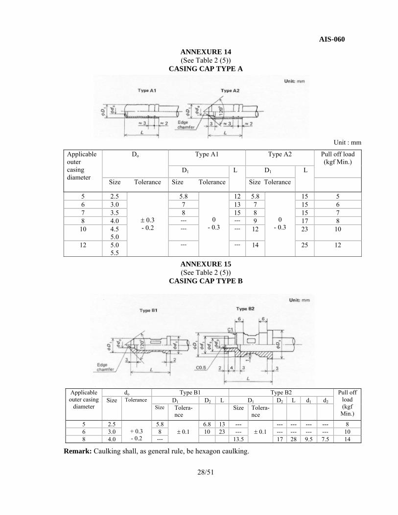
ANNEXURE 14 (See Table 2 (5))
CASING CAP TYPE A
Unit : mm
Applicable outer casing diameter
Do Type A1 Type A2
Pull off load (kgf Min.)
D1 L D1 L
Size Tolerance Size Tolerance Size Tolerance
5 2.5
± 0.3 - 0.2
5.8 0
- 0.3
12 5.8 0
- 0.3
15 5 6 3.0 7 13 7 15 6 7 3.5 8 15 8 15 7 8 4.0 --- --- 9 17 8 10 4.5
5.0 ---
---
12 23 10
12 5.0 5.5
---
---
14 25 12
ANNEXURE 15 (See Table 2 (5))
CASING CAP TYPE B
Applicable outer casing
diameter
do Type B1 Type B2 Pull off load (kgf
Min.)
Size Tolerance D1 D2 L D1 D2 L d1 d2 Size Tolera-
nce Size Tolera-
nce
5 2.5 + 0.3 - 0.2
5.8 ± 0.1
6.8 13 --- ± 0.1
--- --- --- --- 8 6 3.0 8 10 23 --- --- --- --- --- 10 8 4.0 --- 13.5 17 28 9.5 7.5 14
Remark: Caulking shall, as general rule, be hexagon caulking.
28/51

AIS-060
ANNEXURE 16
(See Table 2 (5))
CASING CAP TYPE C
Unit : mm
Applicable outer casing outer diameter
do Size Tolerance
D Nominal Pitch
D1 *d1 Size Tolerance
C1 Type L l
C2 type L l1 l2 B
Pull off load (kgf Min.)
5 2.5
+ 0.3 - 0.2
6 1.0 7 4
+ 0.3 - 0
33 17 28 12 4 10 8 43 27 38 22
6 3.0 6 8
1.0 1.25
8 6 36 17 31 12 5 12 10 46 27 41 22
7 3.5 8 1.25 9 6 48 27 33 12 5 12 12 58 37 43 22
8 4.0 10 1.25 10 7.5 48 27 38 17 5 14 14 58 37 48 27
9 4.5 10 1.25 11 7.5 61 37 41 17 5 14 16 71 47 51 27
10 4.5 5.0
10 1.25 12 7.5 63 37 43 17 5 14 18 73 47 53 27
12 5.0 5.5
12 1.25 14 9.5 76 47 46 17 6 17 22 86 57 56 27
13 5.8 12 1.25 15 9.5 78 47 48 17 6 17 24 88 57 58 27
Remarks 1. Dimensions d1 (dust cover setting groove) with * mark in table may be abbreviated. 2. ** marked chamfer part may be abbreviated. 3. Screw threads shall conform to JIS B 0205 or JIS B 0207. 4. Caulking shall, as general rule, be hexagon caulking.
29/51

AIS-060
ANNEXURE 17
(See Table 2 (5))
CASING CAP TYPE D1
Unit : mm
Remarks 1. Dimension D1 in the Table indicates the case of die cast part or machined part (with * mark). 2. Caulking shall, as general rule, be hexagon caulking.
30/51
pplicable outer casing outer diameter
do Size Tole- rance
D Size Tole- rance
D1 (Ref-erence
D2 d1 Size Tole- rance
d2 L (Ref-erence
l1 l2 Size Tole- rance
L3 Pull off
load (kgf
Min.) 7 3.5
+ 0.3
- 0.2
1.3
±0.2
10 (*) 9
16
9.5
+ 0.3 0
12
30 2.5
2.5
±0.2
---
12
3.5 1.0 8 4.0 11
(*) 10 33 2.8 ---
14
3.5 1.0 10 4.5
5.0 13
(*) 12 36 3.5 1.0 18
3.0 4.5 2.0 12 5.0
5.5 15
(*) 14 40 3.5 1.0 22
4.5 2.0
AIS-060
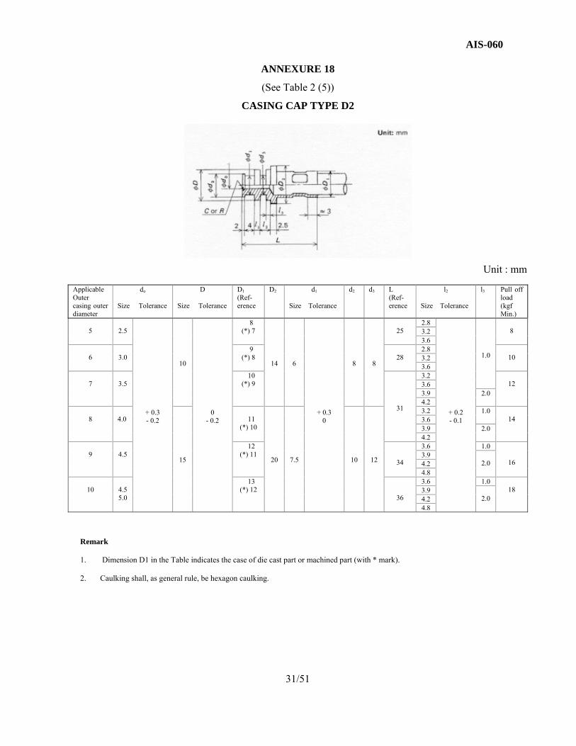
ANNEXURE 18
(See Table 2 (5))
CASING CAP TYPE D2
Unit : mm
Remark 1. Dimension D1 in the Table indicates the case of die cast part or machined part (with * mark). 2. Caulking shall, as general rule, be hexagon caulking.
31/51
Applicable Outer casing outer diameter
do Size Tolerance
D Size Tolerance
D1 (Ref-erence
D2 d1 Size Tolerance
d2 d3 L (Ref-erence
l2 Size Tolerance
l3 Pull off load (kgf Min.)
5
2.5
+ 0.3 - 0.2
10
0 - 0.2
8 (*) 7
14
6
+ 0.3 0
8
8
25
2.8
+ 0.2 - 0.1
1.0
8 3.2
3.6
6
3.0 9
(*) 8
28 2.8
10 3.2 3.6
7
3.5
10 (*) 9
31
3.2 12 3.6
3.9 2.0 4.2
8
4.0
15
11 (*) 10
20
7.5
10
12
3.2 1.0 14 3.6
3.9 2.0 4.2
9
4.5
12 (*) 11
34
3.6 1.0
16 3.9
2.0 4.2 4.8
10
4.5 5.0
13 (*) 12
36
3.6 1.0 18 3.9
2.0 4.2 4.8

AIS-060
ANNEXURE 19
(See Table 2 (5))
CASING CAP TYPE D3
Unit : mm
Applicable outer casing outer diameter
do Size Tolerance
D Size Tolerance
D1 (Refer-ence)
D2
d1 Size Tolerance
d2 D3 L (Refer- ence)
L1 Size Tolerance
Pull off load (kgf, Min.)
7 3.5 + 0.3 - 0.2
13 ± 0.2
10 (*) 9
13
7.5
+ 0.3 0
10
7 42 15
± 0.2
12
9 4.5 15 12 (*) 11
15 9 45.5 16
10
4.5 5.0
16
13 (*) 12
16
10
47.5 18 52.5 20
62.5 30
Remarks
1. Dimension D1 in the Table indicates the case of the die cast part or machined part (with * mark).
2 Caulking shall, as general rule, be hexagaon caulking.
ANNEXURE 20
(See Table 2 (5))
CASING CAP TYPE D4
Unit : mm
Applicable outer casing outer diameter
do Size Tolerance
D Size Tolerance
D1 (Ref- erence
D2 d1 Size Tolerance
D2 L (Refer- ence)
l1 L2 Size Tolerance
Pull off load (kgf, Min.)
8 4.0 + 0.3 - 0.2
16.5 ± 0.1 10 20 7.5 + 0.3 0
10 35 5 3 ± 0.2 25
Remark : Caulking shall, as general rule, be hexagon caulking.
32/51

AIS-060
ANNEXURE 21 (See Table 2 (6)) ADJUST BOLT
Unit : mm
Applicable Casing Cap Type A1 and A2 Outside diameter
do Size Tolerance
D1 Size Tolerance
D Nominal Pitch
B L l1 L2
5.8 3.0
+ 0.5 - 0.2
5.9
+ 0.3 0
8 1.25 10 38 20
12 7 2.8
7.1
6 1.0 10
58 40 3.0 8 1.25 38 20
53 35 8 4.0 8 1.25 12 58 40
8.1 10 1.25 43 14
Remark : Screw threads shall conform to JIS B 0205 or JIS B 0207.
ANNEXURE 22 (See Table 2 (7)) ADJUST NUT
Unit: mm
Applicable casing cap Type C and Adjust Bolt diameter
D Nominal Pitch
B d1 Size Tolerance
d2 L a b H
6 6 1.0 10 7.5 + 0.3
0
10 11 2 4 5 8 8 1.25 12 9.5 12 15 3 6 610 10 1.25 14 11.5 14 11 2 4 5
Remark : Screw threads shall conform to JIS B 0205 or JIS B 0207.
33/51

AIS-060
ANNEXURE 23
(See Table 2 (8))
ROUND JOINT TYPE A 1
Unit : mm End shape θ(0) R l1 l2
Type I & II
90 30
45
40 110
130
34/51

AIS-060
ANNEXURE 24
(See Table 2 (8))
ROUND JOINT TYPE A 2
Unit : mm
End shape θ (0) l1 l2 Type I & II
90 40
40 110
130
35/51

AIS-060
ANNEXURE 25
(See Table 2 (8))
ROUND JOINT TYPE B 1
Unit : mm
Diameter of applicable
outer casing
End shape θ(0) R l1 l2 Pull-off load (N)
6
Type I & II
90 25
40
40
100 or more
100 120 30
36/51

AIS-060
ANNEXURE 26
(See Table 2 (8))
ROUND JOINT TYPE B 2
Unit : mm Diameter of applicable outer casing
End shape
d1
d2
d3
d4
l1
l2
l3
l4
a
Pull off
load (N)
5 Type I 5.1 7.1 3.0 6.0 45 55 25 M8x1.25 80 or more 80 40
6 Type II 6.2 9.1 4.2 7.5 63 70 25 M10x1.25 100 or
more 85 45
7
Type I
7.2
9.1
4.2
--- ---
63
70 25
M10x1.25
120 or
more
85 40 Type II 7.5 70 25
85 40
37/51

AIS-060
ANNEXURE 27
(See Table 2 (8))
ROUND JOINT TYPE B 3
Unit : mm
Diameter of applicable
outer casing
θ(0) R l1 l2 Pull-off load (N)
7
90 30
50
45
120 or more 110
40 130
38/51

AIS-060
ANNEXURE 28
(See Table 2 (9))
CASING PROTECTOR
Unit : mm
Applicable outer casing diameter
D Size Tolerance
t Size Tolerance
L Size Tolerance
5 5.5
± 0.3
1.0 1.5
± 0.3
40 60 80 100 125 150 175 200 225 250 275 300 325 350 375 400 425 450 475 500
± 5% For minimum value of L shall conform to ± 5.
6 6.5 7 7.5 8 8.5
1.0 1.5 2.0
9 9.5 10 10.5 12 12.5 13 13.5
Remarks 1. Casing protector shall, as general rule, be secured with adhesive or other proper method so as to prevent
shifting easily from the designated position on outer casing. 2. Casing protector with dimension L exceeding 500 shall be by agreement between the persons concerned.
39/51
AIS-060
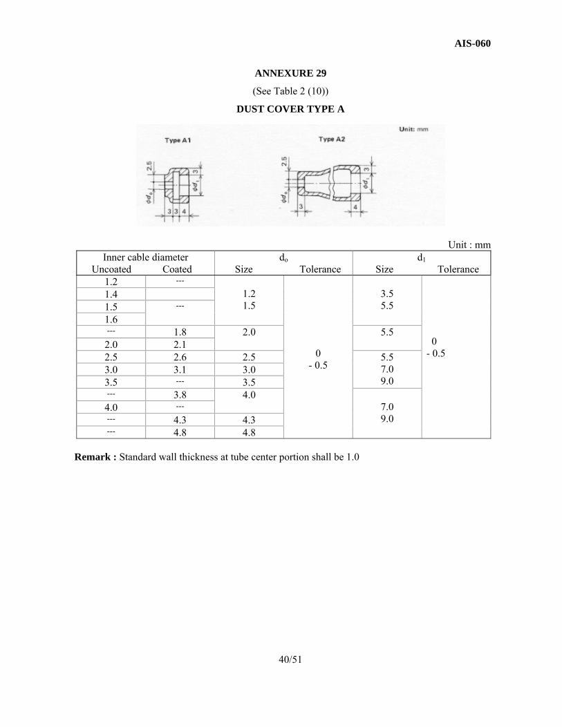
ANNEXURE 29
(See Table 2 (10))
DUST COVER TYPE A
Unit : mm Inner cable diameter
Uncoated Coated do
Size Tolerance d1
Size Tolerance 1.2 ---
1.2 1.5
0
- 0.5
3.5 5.5
0 - 0.5
1.4 1.5 ---
1.6 --- 1.8 2.0 5.5 2.0 2.1 2.5 2.6 2.5 5.5
7.0 9.0
3.0 3.1 3.0 3.5 --- 3.5 --- 3.8 4.0
7.0 9.0
4.0 --- --- 4.3 4.3 --- 4.8 4.8
Remark : Standard wall thickness at tube center portion shall be 1.0
40/51

AIS-060
ANNEXURE 30
(See Table 2 (10))
DUST COVER TYPE B
Unit : mm
Inner cable diameter do d1 Uncoated Coated Size Tolerance Size Tolerance
1.2 --- 1.2 1.5
0
- 0.5
3.5 5.5
0
- 0.5
1.5 --- --- 1.8 2.0 5.5 2.0 2.1 2.5 2.6 2.5 5.5
7.0 9.0
3.0 3.1 3.0 3.5 --- 3.5 --- 3.8 3.5
4.0
7.0 9.0
4.0 --- ---
4.3 4.0 4.8 4.5
Remark : Standard wall thickness at tube center portion shall be 1.0.
41/51

AIS-060
EXPLANATORY NOTE ON CONTROL CABLES FOR AUTOMOBILES
Supplementary explanations shall be given in regard to the contents of this standard. (The following item numbers are identical to those in the text). 3 MAIN COMPONENT MATERIALS AND SURFACE
TREATMENTS 3.1 Inner Cable
(1) In case the corrosion resistance of inner cable is required to be specially
strong, SUS304WR or SUS302WR of JIS G 4308 (Stainless Steel Wire Rods) is recommended.
(2) For inner cable (coated wire) coating material, selection is made from polyethylene, polyacetal, polyamide plastics and the like, depending on the application and type of cable.
3.2 Outer Casing
(1) Polyvinyl chloride is most widely used as coating material for outer casing but there is increasing demand for heat resistance, cold resistance, and other special matters and as materials for these purposes, development is being advanced on various plastics such as polyethylene, polypropylene and polyamide resins. As a result, only synthetic resin was designated in this standard so that actual type of resin and properties shall be as treated as direction to the parties concerned.
(2) For the outer casing (synthetic resin tube), material mainly used are polyethylene, polypropylene, and polyacetal resins, but for the same reason given above, only synthetic resin was designated so as to leave the details agreed on between the parties concerned.
3.3 Cable End
The material differs depending on the part shape, dimensions, and whether the connecting method with inner cable is by caulking or casting in, and selection made from materials such as BsBM of JIS H 3422 (Free Cutting Brass Rods), S15C ~ 35C of JIS G 4051 (Carbon Steel for Machine Structural Use) and ZDC of JIS H 5301 (Zinc Alloy Die Castings).
42/51

AIS-060
4. SHAPES AND DIMENSIONS OF MAIN COMPONENTS 4.1 Inner Cable (Annexure 1, 2, 3 and 4)
(1) Tolerance In the tolerances, there are those on the minus side but only those on
plus side were taken, using JIS G 3535 as reference. For nominal diameter 2.0 and under, plus side 0.1 nominal diameter, and for nominal diameter 2.5 and above, plus side 0.08 nominal diameter were established as basis.
(2) Elongation Since the yield point does not appear clearly in steel stranded cable,
tensile load corresponding to 60 percent of designated breaking load was added, and indicated with the elongation investigated at that time as reference.
(3) Inner cable (coated cable) The minimum wall thickness designated indicates the value that shall
be required for minimum assurance in case of eccentric wall thickness in resin coating.
4.2 Outer Casing (Annexure 5 and 6)
(1) Standard strand diameter has been indicated here as reference to express the workability from round wire.
(2) Outer casing (resin tube) is normally formed using single resin but
different resins may be used to form two-layer casing. 4.3 Cable End
(1) It is necessary that the cable end pull off load be a value that satisfies the operating conditions and safety factor but as this is largely influenced by the cable end shape and size and inner cable diameter, the value for cable ends used on same inner cable diameter, as principle, is set to the same value.
(2) Solder penetration length is defined as the length of the part, in which
during the soldering of the cable end, the solder had been drawn up into the cable by capillary action and hardened.
(3) When joining the inner cable (coated cable) to cable end, the standard
method is to peel off the coating as indicated below before joining.
43/51
AIS-060
(a) Type A cable end (Annexure 7) Joining method with inner cable is mainly by soldering but those made by die
casting (inner cable cast in) are increasing. On the pull off load, die cast formed type is generally higher and although this type has little dispersion in manufacturing, the use of metal mold makes it unsuited for small volume production.
(b) Type B cable end (Annexure 8) The method of making up a connector combination with type A or type B
cable end is generally cheaper than type B1, but there is an advantage in using die cast formed cable end line type B2.
(c) Type C cable end (Annexure 9) When installing, the type conforming to the shape of companion hardware is
selected. (d) Type D cable end (Annexure 10) Type D cable end is utilized when inner cable installed length is to be
adjusted. Caulking method most largely used is square caulking, but other caulking method may be used if pull off load is satisfied.
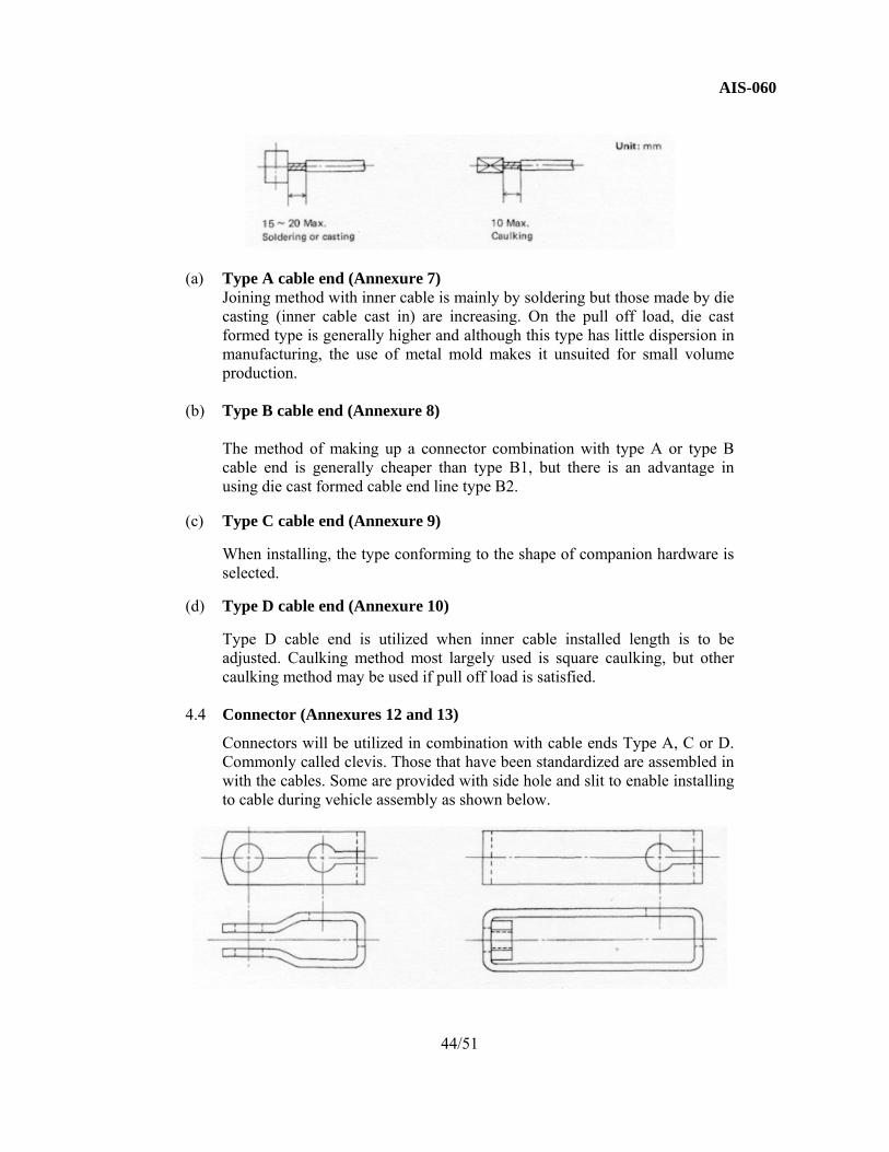
4.4 Connector (Annexures 12 and 13)
Connectors will be utilized in combination with cable ends Type A, C or D. Commonly called clevis. Those that have been standardized are assembled in with the cables. Some are provided with side hole and slit to enable installing to cable during vehicle assembly as shown below.
44/51

AIS-060
4.5 Casing Cap
(1) Type A casing cap (Annexure 14) Type A casing cap will be used by fitting into companion hole like
adjust bolt or clamped by suitable companion hardware. (2) Type B casing cap (Annexure 15) Type B casing cap will be used by fitting into companion hole and
securing the brim.
(3) Type C casing cap (Annexure 16) Type C1 is installed on outer casing with double nut to permit adjusting
the length. Type C2 is a general fixed system. (4) Type D casing cap (Annexure 17 ~ 20) Type D casing cap will be fitted into companion hole and fixed by use
of wave clip, E ring, needle clip and the like. Classified into Type D1, D2, and D3 by the method used for fixing. Type D4 is secured by force fit method.
4.6 Adjust Bolt (Annexure 21) Adjust Bolt will utilized in combination with Type A casing cap for adjusting
outer casing installed length. 4.7 Adjust Nut (Annexure 22) As special nut for installing dust cover, Adjust Nut will be used in
combination with Type C casing cap or adjust bolt. 4.8 Casing Protector (Annexure 28) In regard to length, those exceeding 500 mm were considered to be free. 4.9 Dust Cover (Annexure 29 and 30) On the tightening of the assembling portion, the inner diameter do that
directly cover the inner cable was prescribed to be equal to or slightly smaller than the inner cable diameter and the inner diameter d1 that covers the casing cap or adjust nut at the outer casing side was prescribed to 0.5 mm smaller than the outer diameter of fitting part.
45/51

AIS-060
5. QUALITY 5.1 Dimensions and Tolerance
(1) On proper use of "medium class" and "rough class" in JIS B 0105, general practice is to use medium class. On lengthwise dimension, rough class is sometimes used.
(2) On proper use of "Class 2" and "Class 3" in screw thread accuracy, Class 2 is generally used and on nuts, Class 3 is partially used.
(3) On cable length dimensions, it is desired that these be determined by outer casing overall length (with cap and inner cable exposed lengths a + b. (Main Text Table 5-1). On cable where construction necessitates use of dust covers at inner cable exposed part, there is difficulty in bringing the exposed parts to one place for measurement. In regard to this, it was decided to determine the dimension as inner cable overall length (with cable end) L1 indicated in Main Text Table 5-2. On designating the inner cable nominal length, this may be done to comply with the individual demand items.
6. TEST METHODS
(1) Load speed in strength test
In the strength tests such as inner cable breaking test and cable end and casing cap pull-off load test, it is known that high value will be indicated when the load speed is too fast so that speed not exceeding 50 mm/min. was adopted, taking into consideration working efficiency.
(2) Operating efficiency
It was decided to indicate the operating efficiency in terms of load efficiency and stroke efficiency.
(a) Load efficiency test In general, load efficiency indicates better value when the load W
at the operated side is high than when low. This could be considered as being due to the effects of dust cover tightening allowance, lubricating oil and grease viscosity, and other being more readily received. On the operating side load F, considerable amplitude will be recorded by oscillograph in case of sticking or slipping. In such cases, the central value should be indicated. The faster the operating speed at measurement, the greater will become the amplitude but there will be no transition in the central value. It could be considered that some relation may exist between the amplitude size and the operating smoothness or feeling but this could not be clarified quantitatively.
46/51

AIS-060
The load efficiency differs depending on the curved state of the outer casing. It is known that the following experimental equation obtained based on the contacting angle of the outer casing and inner cable at the curvature part shows highly accurate estimation when the outer casing is bent with in the range of R100 to 300, this could be utilized as necessary. n
Load efficiency η = c-µΣθ where µ : Coefficient of friction n Σθ : Contact angle between outer casing and inner cable n In regard to Σθ, examples of single and multiple curves will be indicated in Explanatory Note Fig. 1.
Explanatory Note Fig. 1
In general the equation will be as follows in case on n number of multiple curves. n n Σθ = nπ - Σθ1 When the outer casing curved part is properly supported along a round plate, it has been found that the load efficiency will be somewhat improved. This could be considered as being due to the buckling trend of outer casing being prevented. It is now becoming a general practice to coat the inner cable with synthetic resin or utilize synthetic resin tube as means of raising load efficiency.
(b) Stroke efficiency test The equation indicated in Main Text 6.1.3 (2) expresses the case
of stroke loss resulting from apparent elastic elongation (inner cable elastic elongation and outer casing elastic contraction). Operating play resulting from apparent permanent elongation (inner cable permanent elongation and outer casing permanent contraction) is not included.
On the inner cable elongation, measurements can be made with relative ease, and moreover, the inner cable can be utilized alone.
47/51

AIS-060
Taking these into consideration, the reference values and test
method have been indicated in Main Text Annexures 1 and 8.
On the outer casing contraction, casing is difficult to measure by itself and in addition, it is used in combination with the inner cable. These have been taken into consideration, resulting in deciding to represent this by stroke efficiency test prescribed in Main Text 6.1.3 (2). In the stroke efficiency test, load elongation curve is derived, and by deriving that for the inner cable separately, it will be possible to estimate that for the outer casing alone from the curve.
As a means of raising the stroke efficiency, presetting the strands
in the inner cable is sometimes practiced. By presetting, the apparent elasticity of the inner cable will be raised but this amounts to only a few percent and has little effect on improving the stroke efficiency. It should also be noted that this will not constitute a positive countermeasure in removing the operating play.
In case of stranded cable in general, as shown in Explanatory Note Fig. 2, for the same nominal diameter inner cable, the single has less elongation than the multi type. For the same load and with same composition, the larger the nominal diameter, the less will be elongation. These facts should be taken into consideration.
Explanatory Note Fig. 2
(3) Outer Casing Buckling When tensile operating load is impressed, the outer casing is subjected to
compressive load and may indicate buckling trend. Functional impedance caused by buckling would first of all be loss in stroke
efficiency. Aside from this, if the buckling becomes large enough to make it difficult to return to original shape, it could result in improper operation.
According to the results of various observations, it was found that buckling
had adverse effect on load efficiency and control feeling.
48/51

AIS-060
The general tendency for buckling to develop has been found to start by
buckling in installed surface outer direction, followed by inside surface, and when both occur, the operating efficiency drops.
When at surface outer buckling, elastic recovery is generally possible but
surface inner buckling is sometimes accompanied by permanent deformation. On synthetic resin tubes, studies have shown that smaller the outer casing
sectional secondary moment and larger the curve R, the smaller will be the buckling development load. This has been proved both theoretically and experimentally.
As related above, development of buckling is not functionally desirable. It is
necessary to know the pattern of its development but on the general handling of the test method, it would be difficult to define at what point of the buckling deformation the limiting load should be taken. Also, when maximum diameter inner cables were inserted into outer casings of the sizes recommended in this standard, and with tension up to cable breaking load applied under the condition of 90o bend, 180 o bend and 90o successive bends over R 100 ~ 300 curves, no symptoms such as inability to recover elasticity could be observed. Such being the case, test method was not specially prescribed in this standard. However, if it is considered that buckling is mainly developed as an effect of operating efficiency, investigation could be made by detailed performance of operating efficiency test.
Thus, if the operating function should become a special problem or in case of
special application, individual investigation should be made. In the case of utilizing synthetic resin tube for outer casing, precaution should be taken since the bending strength is generally low.
(4) Control Feeling In the control cable functions, aside from operating efficiency, control feeling
or operating smoothness becomes a problem. As a cause for decling in feeling, sticking slipping symptoms can be listed
first. The most effective countermeasure for this would be to plan on lowering the friction. For this, studies in lubrication grease selection and effects of temperature and operating speed would be required. There are also cases where the problem of resonance in the elastic properties of inner cable, outer casing and installation parts have been considered.
In regard to feeling, it would be difficult to indicate this by numerical value
at the present stage. Aside from special examples, this is still in the research stage and is a problem that should be investigated further.
49/51

AIS-060
In relation to the buckling and feeling mentioned above, bending rigidity of
the outer casing becomes a factor. As a simple test method for this, the free bending of a given length outer casing is supported as a cantilever beam is compared.
(5) Control Cable Seal On the preservation of control cable durability, main factors are outer casing
cover maintenance and effectiveness of seals such as dust covers. As a means of raising the sealing property of dust cover, a method widely used is to clamp both ends of the dust cover with steel or aluminum rings. Aside from this, use of packing material such as felt is also utilized.
(6) Functional Deterioration and Longevity by Repeated Operation Repeated operation and also accumulation of running operational conditions
including environmental changes will generally cause deterioration in operating functions. Especially with the lowering of operating efficiency and feeling, operation could become impossible even though inner cable and outer casing remain unbroken.
The subjects that become the object of investigation include the longevity of inner cable and cable ends under corrosion or frictional conditions, apparent accumulative elongation of the inner cable, accumulative elongation of outer casing, changes in frictional resistance and lubricating function, and performance and longevity of the various seals.
50/51

AIS-060
ANNEXURE 31 (See Introduction)
COMMITTEE COMPOSITION
Automotive Industry Standards Committee Chairman
Shri Shrikant R. Marathe Director
The Automotive Research Association of India, Pune
Members Representing
Representative from
Ministry of Road Transport & Highways (Dept. of Road Transport & Highways), New Delhi
Representative from
Ministry of Heavy Industries & Public Enterprises (Department of Heavy Industry), New Delhi
Shri S. M. Ahuja Office of the Development Commissioner, MSME, Ministry of Micro, Small & Medium Enterprises, New Delhi
Shri T. V. Singh
Bureau of Indian Standards, New Delhi
Director
Shri D. P. Saste (Alternate)
Central Institute of Road Transport, Pune
Dr. M. O. Garg Indian Institute of Petroleum, Dehra Dun
Shri C. P. Ramnarayanan Vehicles Research & Development Establishment, Ahmednagar
Representatives from Society of Indian Automobile Manufacturers
Shri T.C. Gopalan Tractor Manufacturers Association, New Delhi
Shri K.N.D. Nambudiripad
Automotive Components Manufacturers Association of India, New Delhi
Shri Arvind Gupta Automotive Components Manufacturers Association of India, New Delhi
Member Secretary Mrs. Rashmi Urdhwareshe
Deputy Director The Automotive Research Association of India, Pune
51/51