Embed Size (px)
Citation preview

7/22/2019 General Honsberg
http://slidepdf.com/reader/full/general-honsberg 1/347
Main Catalogue
Flow Level Temperature Pressure Filtration• • • •

7/22/2019 General Honsberg
http://slidepdf.com/reader/full/general-honsberg 2/347
Honsberg & Co. KG
Tenter Weg 2-842897 Remscheid · Germany
P.O. Box 11 03 6942863 Remscheid · Germany
Tel. +49(0) 2191/9672-0Fax +49(0) 2191/ 9672- 40
www.honsberg.com
[email protected]: Honsberg & Co. KGPrint: Limberg-Druck GmbH
KaarstEdition: 1 /08 /Basic /1E
Flow Level • Temperature • Pressure • Filtration
Basic
7/22/2019 General Honsberg
http://slidepdf.com/reader/full/general-honsberg 3/347
Welcome to Honsberg!
As a familiy controlled enter-prise, we welcome you andappreciate your interest inour products for control andmeasurement of flow, level,
temperature, pressure and
filtration.
Sincerely
M. SeulenOwner – Manager

7/22/2019 General Honsberg
http://slidepdf.com/reader/full/general-honsberg 4/347
Honsberg & Co. KGTenter Weg 2-8 · 42897 Remscheid · GermanyP.O. Box 1103 69 · 42863 Remscheid · GermanyTel. +49(0)2191 9672-0 · Fax +49(0)2191 9672-40www.honsberg.com · [email protected]
2
1963 The company is founded by Prof. G. W. Seulen as amanufacturer of mechanical flow control instruments.
1974 Michael Seulen joins the management. Product rangeis extended to include level, temperature and pressure.New premises in Remscheid Lennep, Tenter Weg.
1977 KTA approval and supplier of flow control technology fornuclear power plants
1980 Start of large-scale production of mechanical monitoring
equipment for OEM customers.
1990 Extension of the product range to include electronicdevices.
1995 Presentation of electronic metering converters for flow,level, temperature and pressure.
1996 Honsberg Smart transducer.Certification to ISO 9001.
1998 Presentation of the integrated transmitter system OMNI.
2000 Reorganisation and expansion of the production division.New office building.
2002 Focus on products and marketing
2004 ATEX certified company
2005 DIN-GOST certified company
The road to success
Basic

7/22/2019 General Honsberg
http://slidepdf.com/reader/full/general-honsberg 5/347
A Piston, valve design Monitoring, indicating, metering 15
B Piston, inline design Monitoring, indicating, metering 51
C Variable area Monitoring, indicating, metering 99
D Paddle, dynamical flap Monitoring, indicating, metering 127
E Rotor, turbine, Monitoring, indicating,161gear and oval wheel metering, counting
F Calorimetric,magnetic-Monitoring, metering 201inductive, vortex
G Sight glass, flap, sphere Indicating 223
H Orifice Regulation, monitoring 235
I Level Monitoring, indicating, metering 243
J Temperature Monitoring, indicating, metering 269
K Pressure Monitoring, indicating, metering 279
L Integrated systemsMonitoring, indicating, metering 297Omni/Flex
M Transducers Signal processing 311
N Filters, accessories Filters, supporting components 321
Flow
Level
Temperature
Pressure
The range
Our aim is to provide industrialplant engineering and process
technology with tried and trustedand economical solutions in theareas of:
l Monitoring threshold value when under-cut or exceeded
l Indicating visual control
l Meteringquantitative statement in theaccuracy range of 3 % orcontinuous signal recordingand transmission in theaccuracy range of 1 %
l Countingimpulse output
l Regulatingflow limitation with orifice
l Transducingsignal transformation,signal processing
l Filteringprotection from dirt,filtration of fluids
Honsberg devices can be foundin wide areas of industry andprocessing in a range of applica-
tions dealing with fluids, aggres-sive and viscous media as wellas air and gases.
The Honsberg range of industrialinstrumentation for

7/22/2019 General Honsberg
http://slidepdf.com/reader/full/general-honsberg 6/347
4
The market is the challenge
Honsberg sales structure
1. engineering2. customized solutions, oem3. (enduser)4. process application5. miscellaneous
1. flow2. level3. temperature4. pressure
1. mechanical instrumentation2. electronic instrumentation
1. domestic market 2. export europe3. export world
Honsberg & Co. KGTenter Weg 2-8 · 42897 Remscheid · GermanyP.O. Box 1103 69 · 42863 Remscheid · GermanyTel. +49(0)2191 9672-0 · Fax +49(0)2191 9672-40www.honsberg.com · [email protected]
Basic

7/22/2019 General Honsberg
http://slidepdf.com/reader/full/general-honsberg 7/347
The systems
The HONSBERG range includes metering and monitoring equip-ment in the accuracy range of up to 0.1 % from the measured
value. HONSBERG technology concentrates on specific mechanicaland electronic systems which are integrated in a variety ofsystems, resulting in an extremely flexible range of applications.
Advantages Disadvantages Application Principle
l Sturdy mechanics l High pressure loss Universal use Pistonl Good repeatability for liquids spring-supported
and gases (path recording)l Industry, e.g.
transfer linesl Purely physical l Only for transparent Metering of Variable area
floating principle media transparent liquids (path recording)l High accuracy l Defined installation and gases
position l Laboratoryl Medical technology
l Low pressure l Higher functional Yes/no control Paddleloss tolerance of liquid and spring-supported
l Dirt l Sensitive with gaseous media (path recording)resistant high flow velocities l Heating technology
l Independent of l Transformersnominal diameters
l High accuracy l Limited application Linear frequency Rotor, turbine
for gases and signals (rotation) viscous media l Cooling systems
l High accuracy l High pressure loss Linear frequency signals Gear wheel,l Volumetric, l Oil circulation oval wheel
thus independent l Collet chuck (rotation)of viscosity
l No moving l Limited application Sensor technology Calorimetric,parts for gases and oils l Welding robots magnetic,
l Independent of l Inductive only for l Waste water inductivenominal diameters conductive liquids systems (temperature
difference,inductive)
l Linear method l Sensitive to Level monitoring Levelchanges in density and metering Float,
l Tanks sight glass(path recording)
l Proven method l Linearity Temperature Temperatureof monitoring deviation in monitoring and diaphragm,and metering the lower range metering platinum,
temperature l Industrial systems resistance-sensor
l Linear transmission l Diaphragm sensitive Pressure monitoring Pressureof motion to high pressures and metering Piston, diaphragm,
l Gears piezoresistive strainrelief element
5

7/22/2019 General Honsberg
http://slidepdf.com/reader/full/general-honsberg 8/347
Honsberg & Co. KGTenter Weg 2-8 · 42897 Remscheid · GermanyP.O. Box 1103 69 · 42863 Remscheid · GermanyTel. +49(0)2191 9672-0 · Fax +49(0)2191 9672-40www.honsberg.com · [email protected]
Basic
6
The Honsberg Technology
The Honsberg technology for monitoring and metering flow, level, tem-perature and pressure is based on the principle of inductive magneticcoupling of movement of a spring-supported base or rotating element fitted with a magnet. This unit is located in the hydraulic area andactuates contacts, display units or integrated electronic circuits outside
the media space according to specific parameters.Using this method, switch contacts are triggered, dials actuated,
visual display elements activated or continuous output produced in apre-defined position which corresponds to the operating parameterrequired.
This technology results in significant advantages during operation:l No sealing problems thanks to inductive triggering from within
the media spacel Installation can be in any position thanks to spring support l High pressure and temperature loadl Straightforward servicing since separated from hydraulic and
electric componentsOther technologies include the metallic activation of an inductive proximi-
ty switch, activation of an optical sensor, electronic evaluation of tem-perature and pressure sensors or the direct triggering of a switchcontact, metering unit or integrated electronic circuits.
Flow Level Temperature Pressurel/min mm °C bar
The componentsComponent
Magnet
Spring
Reed-switch
Mikro-switch
Hall-Sensor
Inductiveproximity switch
Opticalsensor
Mechanicaldial unit
Integratedsystems
Task
Triggering
Deflection,reset guaranteeThreshold contact,break contact,make contact orchangeover contact
Threshold contact,changeover contact
Sensor signalPNPNPN
Dial display
LCD displayThreshold values0..10 V,0(4)..20 mA
Design
Ring, cylinder
Tension orpressure springMagnetic
triggering
Mechanicalor magnetic
triggeringMagneticactivationMetallicactivation
Opticalactivation
Dial unit withmagnetic ormechanical
triggering
Advantages
Inductive triggeringReliableresettingLow hysteresis, nomechanical triggeringcomponents
Spring-supported switch-ing characteristics, highswitching capacitySensor in metal housingfor high pressuresUniversal applications,without magnetic
triggering componentsSensor without additional triggeringcomponentsReliable high-resolutionmechanical scalesystem
Compact design fordisplaying threshold
values and continuouspaging
The technologies:
Spring-supported magneticcontact control
Display options:Triggering of mechanical metering
units or digital sensor systems
inductivemag.
inductivePT 100 piezo
thick film
optical
calor imetr ic diaphragm
7/22/2019 General Honsberg
http://slidepdf.com/reader/full/general-honsberg 9/347
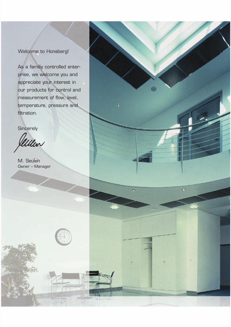
Handling
One important requirement of product development is simple and safeproduct handling. On the one hand, this refers to the installation inmechanical, electrical and electronic terms, and on the other the cali-bration and setting of the instruments.
Mechanical installationThe following standard options are available in housing form:
l Female threadsl Flanges
The following standard options are available in stub-connection form:l Male threadsl Flangesl Solder, welded stub-connections
Electrical installationStandard installation of the devices is via plug or cable.Wiring is according to the connection diagram provided.
Reed, micro-switchesThe reed switch consists of contact tongues arranged in a pipe eitherevacuated or filled with inert gas, the micro-switch works on the basisof mechanical contact control.When connecting the switch it is mandatory that a consumeris connected in series. It must be guaranteed that the given valuesfor voltage, current and capacity are not exceeded.
l Switching voltage V ACl Switching current Al Capacity VA
Contact materiall Reed switch Ruthenium, rhodium, tungstenl Micro-switch Silver, gold
Electronic sensorsl Inductive proximity switches Triggered by metall Hall sensors Triggered by magnet l Optical sensor Optical triggering
NPN/PNP electrical data according to data sheet
CalibrationThe devices can either be factory-adjusted with documentation or cali-brated during customer commissioning.
Bus applicationsThe Honsberg oil distribution system is compatible to mostly any BUS
Systems via the "Murr Cube System". Please contact us to get detailedinformation.4..20mA => cube 67 (analog input) =>Bus interface => reduce 16 wires to one
Reed switch
l high switching speedl tight hysteresis
Micro-switch
l mechanical step characteristicsl high switching power
Hall sensor
l wear-freel high responsiveness
7

7/22/2019 General Honsberg
http://slidepdf.com/reader/full/general-honsberg 10/347
8
Honsberg & Co. KGTenter Weg 2-8 · 42897 Remscheid · GermanyP.O. Box 1103 69 · 42863 Remscheid · GermanyTel. +49(0)2191 9672-0 · Fax +49(0)2191 9672-40www.honsberg.com · [email protected]
Basic
The variety
Working principle Basic device VariationsPiston Monitor Magnetically coupled dial Magnetically triggered transducer
Adjustable contact for local measurement with switch PNP and NPN,of a reed or 4[0]..20 mA and LCD displaymicro-switch
Paddle Monitor Magnetically coupled dial for local measurement Adjustable contact with adjustable integrated threshold
of a reed ormicro-switch
Rotor Frequency-transmitting Sensor options Integrated transducer transmitter switch, 4… 20 mA output with switch PNP and NPN,
4[0]..20 mA and LCD display
Calorimetric Monitor with Transmitter
LED indication and with switch PNP or NPN,potentiometer 4[0]..20 mA or 0 … 10 V setting with and without LCD display
Level Transmitter with Transmitter4 … 20 mA with switch PNP or NPN,
4[0]..20 mA or 0 … 10 V with and without LCD displayTemperature
Pressure
The Honsberg range has an extremely modular structure andmakes flexible adaptation of applications for our devices possible
thanks to the combination of standard components.

7/22/2019 General Honsberg
http://slidepdf.com/reader/full/general-honsberg 11/347
9
Application Commands Selection
The Honsberg range of devices has a modular structure and this offers a wide range of applications.
Specification Chapter Systems Equipment
Large nominal sizes >DN50 l A l Piston valve design l PD, VI, TX, TZ1, VD, VDO, VMl D l Paddle l CM2K, CRG, UB1, UM3K, UR1,
UR3K, VM, TZ1l E l Rotor l RR.-032l F l Calorimetric l EFl F l Magnetic-inductive l FIS
Low flow rates < 1l/min l A l Piston valve design l FF, FM, Gl B l Piston inline design l FW3, FX, HD1K, HD2K, HM1K, MF,
MR, MR1K, RVM, VF, VOl C l Variable area l GK, GR, MMF, UK, VLl E l Rotor l PO, RL, WR1, RA, RH, RRI, RRH, RROl E l Turbine l ROl E l Gear wheel l VHZl F l Oval wheel l VHOl F l Calorimetric l EF
High operating pressure >200 bar l B l Variable area l HD1K, HD2K, HM1K, MR1K, RVMl E l Turbine l RT
High temperatures >120°C l A l Piston valve design l MXO, MXR, TX l D l Paddle l UB1l E l Turbine l RT
Aggressive media l B l Piston inline design l HD1K, HD2K, HR1MV, MI, MR, MR1K,NJ, NJ, NO, VF, VO
l C l Variable area l VLl D l Paddle l CRG, UB1l E l Rotor l RROl E l Turbine l RTl F l Calorimetric l EFl F l Magnetic-inductive l FISl G l Sphere l BL
Announcement of dirty media l A l Piston valve design l MP, MXO, TZ1, VDOl B l Piston inline design l NJ, NJV, NO
Viscose media up to 350 mm 2/s l A l Piston valve design l FF, FM, G, MP, MXR, PD, TX, TZ1, VD, VDO, VI, VM
l B l Piston inline design l FW1, HD1K, HD2K, HR1MV, MR,MR1K, NJ, NJV, VF, VO, MI
l D l Paddle l CM2K, CRG, TZ1, UB1, UI, UM3K,UR1, UR3K, VM, UZ
Viscosity-compensated 1-200 mm²/s l B l Piston inline design l HD2K, HR1MV
Viscosity-independent to 1000 mm²/sl
El
Gear wheell
VHZl E l Oval wheel l VHOAir and gas l A l Piston valve design l Alle
l B l Piston inline design l FX, FW1, HD1K, HR1MV, MF, MI, MR,MR1K, NJ, NO, VF, VO
l C l Variable area l Allel D l Paddle l UI, UM3K, UR1, UR3K, YRl E l Rotor l PO, WR1, RRI, RRH, RROl G l Sphere l BL
Approvals Chapter Systems Equipment
Atex l A l Piston valve design l VD, VMI M1 EEx ia I l B l Piston inline design l HD1K, HD1KV, HR1MV II 1G EEx ia IIC T4 l D l Paddle l UR1, VMII 1D EEx iaD 20 T135 l I l Float l NW1Atex l A l Piston valve design l VMII 2G EEx D IIC T6 l D l Paddle l VMGL - Germanischer Lloyd l A l Piston valve design l G, VD
l B l Piston inline design l HD1K TÜV l A l Piston valve design l TX
l D l Paddle l CRGl D l Paddle l UB1
Flow

7/22/2019 General Honsberg
http://slidepdf.com/reader/full/general-honsberg 12/347
Flow Level Temperature Pressure Filtration
10
Honsberg & Co. KGTenter Weg 2-8 · 42897 Remscheid · GermanyP.O. Box 1103 69 · 42863 Remscheid · GermanyTel. +49(0)2191 9672-0 · Fax +49(0)2191 9672-40www.honsberg.com · [email protected]
Basic
Compressor
High Pressure Cleaners
Paper Machine
Machine Tool
Honsberg at work
Honsberg products can be found in a wide variety of applications andas original equipment components in industrial plant engineering.
Application Equipment Chapter / Systeml clamping cylinder l VHZ l E gear Wheell compressor l FF l A piston valve designl construction machines l NR l H levell cooling circuit l RRI l E rotorl cooling unit l FW1 l B piston inline design
l RRI l E rotorl
dental chairl
MFl
B piston inline designl diesel engines l G l A piston valve designl earth moving l NR l H level
machinery l gearing mechanism l NJ, NJV l B piston inline designl power generation l VD l A piston valve designl heating engineering l UM3, UR1 l D paddle
UR3l high pressure cleaners l MR l B piston designl induction hardening l RRI l E rotor
equipmentl
industrial furnacesl
KMl
I orificel injection moulding l ZE l N filtermachine
l laboratory equipment l UK l C variable areal laser technology l RRI l E rotorl machine tool l MR l B piston inline designl medical technology l MMF l C float l mobile automatic l FX l A piston valve design
weldersl multi-circuit system l RRI l E rotorl oil circulation l HD2K l B piston inline designl
oxygen supply l MMF l C variable area
l paint finishing system l MR1K l B piston inline designl paper machine l NJ, NJV l B piston inline designl printing machine l FW1, OT l B piston inline design
dehumidifier l UR l D paddlel pressure increasing l TF1 l J temperature
systeml printing machine l PM l K pressure
pollinatorl seewage technology l FIS l F magnetic-inductivel steel mill l UZ l D paddlel swimming pool l UR l D paddlel transformer l UB1, CM2K l D paddlel tunelling machine l omni-F l F calorimetricl vacuum pumps l PM l K pressurel welding robots l EFK l F calorimetric

7/22/2019 General Honsberg
http://slidepdf.com/reader/full/general-honsberg 13/347
11
Transformers
Semi-conductor industry
Swimming pools
Welding robots
Piston valve design
l Monitoring of coolant in cold compressors
Piston inline design
l Protection against no-flow conditions e.g. high-pressure cleanersl Monitors emulsion supply e.g. tool machinesl Monitors and measures oil supply to large-scale gear systems
e.g. paper machinesl Monitors multi-circuit systems
Paddles
l Monitors oil flow in transformersl Flow-dependent control of gas valves, combination boilersl Monitors the addition of chemicals e.g.
in swimming pools
Rotors
l Measures and monitors in semi-conductor technologyl Measures and monitors multi-circuit systemsl Measures and monitors cooling circuits
Gear wheel
l Hydraulic monitoring of clamping cylinders
Calorimetric
l Monitoring of cooling for welding lance in welding robots
Variable area
l Monitoring and measurement of water, oil and dieselin construction machinery
Bi-metal
l Monitoring temperature in booster systems
Diaphragm
l Monitoring of exhaust pressure in vacuum pumps
7/22/2019 General Honsberg
http://slidepdf.com/reader/full/general-honsberg 14/347
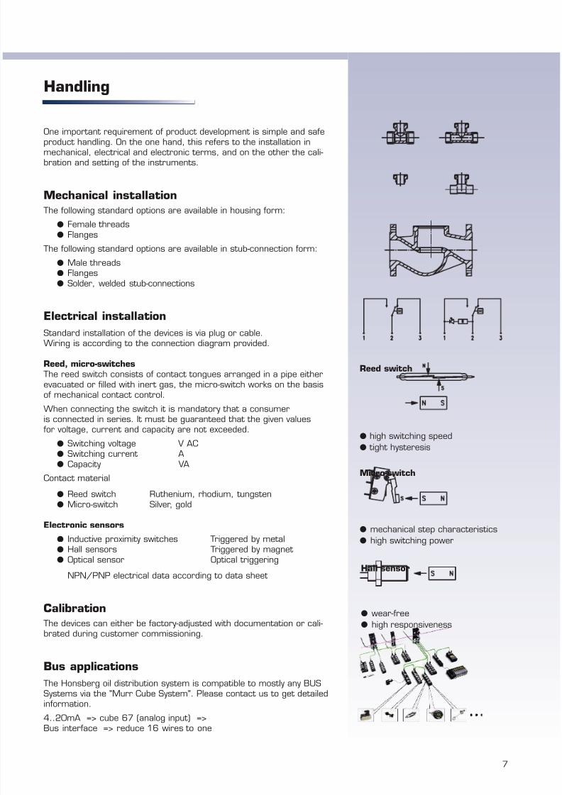
Honsberg market positioning
With its very extensive breadth and depth, the market for measurement and control technology is split into various segments. Each of these hasits own particular requirements and therefore forces small and medium-sized suppliers in particular to specialise and focus on just a few, inorder to optimally position themselves on the market.
1 Process measuring equipment 2 Industrial measurement and control systems3 Medical equipment 4 Chemicals and food5 Other
For many years now, Honsberg has been an established name on themarket for industrial measuring and monitoring systems, and supplies
industrial plant engineering manufacturers with both standard productsand also customised solutions. However, also in this specific market segment, there are various customer profiles whose needs have to beindividually matched in terms of product portfolio, supply capability, levelof after sales service, etc.
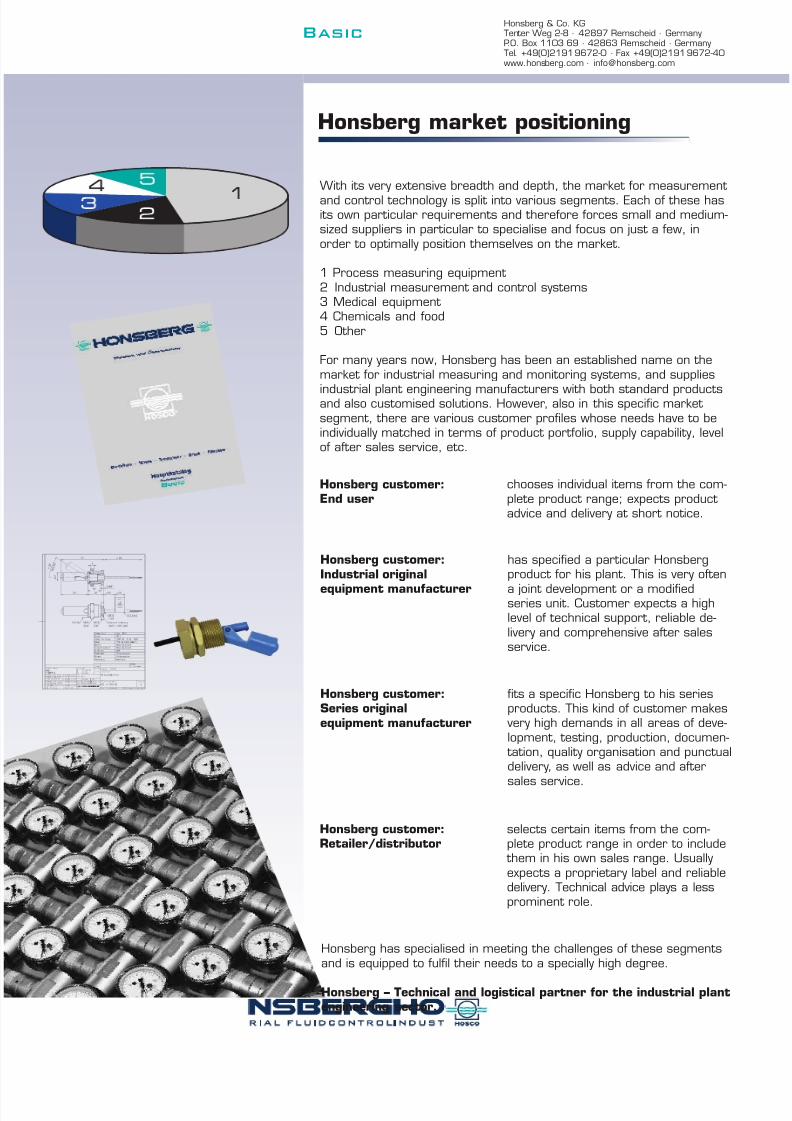
Honsberg customer:End user
chooses individual items from the com-plete product range; expects product advice and delivery at short notice.
Honsberg customer:Retailer/distributor
selects certain items from the com-plete product range in order to include
them in his own sales range. Usuallyexpects a proprietary label and reliabledelivery. Technical advice plays a lessprominent role.
Honsberg customer:Industrial original
equipment manufacturer
has specified a particular Honsbergproduct for his plant. This is very oftena joint development or a modifiedseries unit. Customer expects a highlevel of technical support, reliable de-livery and comprehensive after salesservice.
Honsberg customer:Series originalequipment manufacturer
fits a specific Honsberg to his seriesproducts. This kind of customer makes
very high demands in all areas of deve-lopment, testing, production, documen-
tation, quality organisation and punctualdelivery, as well as advice and after
sales service.
Honsberg has specialised in meeting the challenges of these segmentsand is equipped to fulfil their needs to a specially high degree.
Honsberg – Technical and logistical partner for the industrial plantengineering sector.
Honsberg & Co. KGTenter Weg 2-8 · 42897 Remscheid · GermanyP.O. Box 1103 69 · 42863 Remscheid · GermanyTel. +49(0)2191 9672-0 · Fax +49(0)2191 9672-40www.honsberg.com · [email protected]
Basic

7/22/2019 General Honsberg
http://slidepdf.com/reader/full/general-honsberg 15/347
milling machine
cell assembly
test rig
labeling
Honsberg Produktion
The assembly is organised on basis of specific rigassisted stations partly in the format of assembly cells.Honsberg exercises the FVS system (Full ValueStream), which implies a full chain of value generationin the cell environment.
Modern machine tools manufacture the Honsbergspecific components.
Subsequent to a 100 % functional test the finishedproduct is assigned to a product identification numberwhich allows constant tracebility. The completion iseither customer- or stock related. Honsberg keeps acomprehensive level of finished products in order toship ex stock if required.The shipment of Honsberg products is assigned tocertified transport organisations.
Integrated assembly, testing and packing
Order processing and shipment data are registered bya visual system and are instantly available.
13

7/22/2019 General Honsberg
http://slidepdf.com/reader/full/general-honsberg 16/347
14
Honsberg & Co. KGTenter Weg 2-8 · 42897 Remscheid · GermanyP.O. Box 1103 69 · 42863 Remscheid · GermanyTel. +49(0)2191 9672-0 · Fax +49(0)2191 9672-40www.honsberg.com · [email protected]
Basic
Honsberg Digital
All up-to-date information is available as PDF fileson our website www.honsberg.com.
In addition, the product CD isavailable, including infor-
mation as Excel andPDF files.

7/22/2019 General Honsberg
http://slidepdf.com/reader/full/general-honsberg 17/347
A
15
Piston valve design
The technology
Magnet-equipped, spring-supportedpiston triggers flow-dependent induc-
tively adjustable threshold contactsor dial units.
Applications
l Industrial metering and monitoring technologyl Cooling systemsl Lubrication circuits
Advantages
l Dirt resistant l High switching capacityl Various materialsl Nominal diameters DN 8 to DN 300
Contents
System descriptionDevice system 16Function and advantages 16Metering materials and accuracy 17Handling and operation 18
Device descriptions 19
l Switchingl Indicatingl Metering
Concept piston, valve designNominal diameter 8 - 300Connection female thread, flange, adhesive fitting, adhesive stub-connectionPN 10 - 200Max. temperature 350 °CSignal threshold, optical display, potentiometerAdjustable yesMaterials red bronze, stainless steel, cast steel, cast iron, PVCInstallation position anyMetering materials liquids or gases
Technical data

7/22/2019 General Honsberg
http://slidepdf.com/reader/full/general-honsberg 18/347
Honsberg & Co. KGTenter Weg 2-8 · 42897 Remscheid · GermanyP.O. Box 1103 69 · 42863 Remscheid · GermanyTel. +49(0)2191 9672-0 · Fax +49(0)2191 9672-40www.honsberg.com · [email protected]
Basic
16
System description
Device system
The piston system with valve design is of particular advantage formetering and monitoring jobs in the area of liquid and gaseous meter-ing materials.
A magnet-equipped piston rests in the valve seat of a housing and ismoved vertically by the flowing medium, whereby the path of the pistonis directly proportional and linear to the flow rate.
Since the piston works against the force of a supporting spring, the devices can be installed in any position and reset safely when
the volume flow diminishes.
Functions and advantages
The device system can be used for metering and monitoring taskswithin the context of the basic design.
It is based on the non-contact coupling of the magnet-equipped pistonin the hydraulic system to external hermetically separated thresholdcontacts or metering devices. In this way, threshold signals are pro-duced or visual displays activated.
Since the contact unit is usually arranged adjustably, an adjustment range for the switching point is realised in the ratio 1:10, whichenables users to set the required value continuously on site with theaid of scale information. The adjustment path is significantly extendedby a coiled groove and displayed on a greatly lengthened scale [VD,
VDO, VM].
In the case of metering devices [TZ1] the piston movement is linkedmagnetically to an actuator part which activates a pointer meteringunit and this makes a display on a 320° scale possible.
In the case of more straightforward versions [MP, VDO] the pointermechanism is replaced by a magnetic ring pointer which is moved by
the primary piston.
The advantages of the piston system are in its particularly sturdydesign, high temperature and pressure resistance and simple yet safehandling during calibration.
The application advantages can be summarised as follows:
l High pressure and temperature resistancel Good soiling resistancel Linear functionl Exact calibrationl Low pressure loss
No flow Flow
Micro-switch Dial VM TZ1
Reed switch Magnetic ring VD MP

7/22/2019 General Honsberg
http://slidepdf.com/reader/full/general-honsberg 19/347
A
17
Metering materials and accuracy
The devices are designed for liquid metering materials as standard and the functional data are specified for water.
The devices can also be used for viscous media and gaseous meteringmaterials.
As far as viscosity is concerned, it must be noted that the metering values decrease as viscosity increases, as shown in the table below
Water Viscosity mm²/s
30 60 115 220 VD 4 2 0.8 0.6 0.25
8 6 4 3 1.510 9 8 6 320 18 17 14 10
VM 4 4 4 3 2.58 8 8 7.5 6
10 10 9 7 620 19 18 17 14
MP 4 4 4 3 28 8 7 6 4
10 10 9 8.5 820 19 18 17.5 17
TZ1 4 4 4 3.5 38 8 7.5 7 6
10 10 9.5 9 820 20 19 18.5 18
In the case of air and gases, the functional ratio in relation to wateris approx. 1:35, i.e. 1 l/min water corresponds to approx. 35 Nl/minair, whereby temperature, density and operating pressure play a specialrole here.
In these cases the devices are tailor-made according to customerspecifications, whereby the mechanical moving parts are equipped withadditional absorption.
We will be happy to give you special advice in these cases.
Devices with a temperature range of up to 350 °C are availablefor higher temperatures.
Type Temperature up to °C Switching IndicationMXR 160 + -MXO 160 optional +
TX 350 + +
MP
VDO
MXR
MXO

7/22/2019 General Honsberg
http://slidepdf.com/reader/full/general-honsberg 20/347
Honsberg & Co. KGTenter Weg 2-8 · 42897 Remscheid · GermanyP.O. Box 1103 69 · 42863 Remscheid · GermanyTel. +49(0)2191 9672-0 · Fax +49(0)2191 9672-40www.honsberg.com · [email protected]
Basic
18
Handling and operation
If the switching point needs to be set, this can be done by adjusting the switching head in a coiled groove [Type VD, VDO, VM] or bylongitudinal adjustment [TX, MX], with the position being chosen
with the aid of a setting diagram and/or a scale.
The function of the threshold valve [TZ1] is either signalled by thesystem or, as an option, can be confirmed by an LED display.
VD
TZ1
F l o w
r a t e
H 2 O 2 0 ° C
Switching head position, tolerance ± 10 % VM-..GR

7/22/2019 General Honsberg
http://slidepdf.com/reader/full/general-honsberg 21/347
A
19
m i s c e
l l a n e o u s
p a g e
a g g r e s s i v e
g a s
/ a
i r
o i l
i n d i c a t i o n
t y p e
c o n t r o
l
c o n n e c t i o n
o u t p u t s i g n a
l
o n s
i t e m e t e r i n g
m a x . p r e s s u r e
b a r
m a x . t e m p
e r a t u r e
° C
w a t e r
n o m
i n a
l d i a m e t e r
HONSBERG & CO.KG Tenter Weg 2-8 42897 Remscheid GermanyTel. +49(0)2191 9672-0 Fax +49(0)2191 9672-40 www.honsberg.com [email protected]
l standard m standard option special option all data sheets available under www.honsberg.com
FF 8 - 40 female thread brass l 200 110 l 3 3 20
FM 8 - 15 female thread bronze l 200 90 l 3 3 22
G 8 - 15 female thread bronze l 16 80 l 3 3 24
VD 8 - 80 female thread bronze l 25 120 l 3 3 268 - 50 female thread stainless steel l 100 120 l 3 3 3 28
VM 8 - 80 female thread bronze l 100 90 l 3 3 308 - 50 female thread stainless steel l 100 90 l 3 3 3 32
VDO 8 - 80 female thread bronze l l 100 120 l 3 3 34
MXR 8 - 80 female thread bronze l m 100 160 l 3 3 36MXO 8 - 80 female thread bronze m l 100 160 l 3 3 37MXM 8 - 80 female thread bronze l l 100 160 l 3 3 37
TX 15 - 200 flange cast steell l
40 350l 3 3
38
MP 8 - 80 female thread bronze l 100 100 l 3 3 40
TZ1 8 - 80 female thread bronze m l l 100 90 l 3 3 428 - 50 female thread stainless steel m l l 100 90 l 3 3 3 44
additional features l l l l 46
PD 8 - 80 glue fitting PVC l 10 60 l 3 3 3 478 - 50 lue socket PVC l 10 60 l 3 3 3 478 - 80 flange PVC l 10 60 l 3 3 3 47
VD 15 - 100 flange bronze l 16 120 l 3 3 4715- 300 flange cast iron l 16 120 l 3 3 4715- 300 flange cast steel l 40 120 l 3 3 4715 - 150 flange stainless steel l 40 120 l 3 3 3 47
VM 15 - 200 flange cast iron l 16 90 l 3 3 47
VI 8 - 80 female thread bronze l 16 60 l 3 3 48
TZ1 65 - 200 flange cast iron m l l 16 90 l 3 3 48 s p e c i a
l a p p
l i c a t i o n
s t a n
d a r d a p p
l i c a t i o n

7/22/2019 General Honsberg
http://slidepdf.com/reader/full/general-honsberg 22/347
Flow Switch 1.1.piston / valve design Novafix FF-...GR FF.GR
GENERAL CHARACTERISTICS Female thread G1/4 to G1/2 bronze
FF-025GR040STECHNICAL DATA
Switch value is indicated for horizontally decreasing flow.
tolerance ±0.3 l/minmedia temperature max. 110°Caverage pressure loss 0.4 bar at Qmax.hysteresis depending on switch value
minimum 0.4 l/min.
MATERIALS
housing bronce Rg5 nickel platedbody brass Ms58 nickel platedpiston stainless steel 1.4305spring stainless steel 1.4310magnet bariumferriteseals NBR
14 2,0
G Type Qmax. recom.l/min H2O
switch value l/min H 2Oselectable range for
fixed switch
Lmm
Hmm
SWmm
52 14
1213
2929
Xmm
1,514 1,0
32 11 0,7
G 1 1/2 FF-040GR090. 16 150 95
412 - 60 98 941,5 - 40 87 90
5916 100
3 - 90 113
73 79G 1 FF-025GR040. 25 60
200 2040 0,6 - 25
79 2915 0,4 - 10 68 79
200G 3/8 FF-010GR010. 200
PNbar
b r o n z e
G 1/4 FF-008GR009.
G 3/4 FF-020GR025.G 1/2 FF-015GR012.
G 1 1/4 FF-032GR060.
0,625
0,4 - 12 68
weightkg
0,60,6
1210 0,4 - 9 68 79
Mechanical Flow Switch for liquids or gaseous media, withspring-supported piston and magnetic triggering of a reedswitch. Rugged design in brass / bronze combination.
fixed switch valuehigh pressure dutygood repeatabilitydirt-resistanthigh switch capability
HONSBERG & CO.KG Tenter Weg 2-8 42897 Remscheid GermanyTel. +49(0)2191 9672-0 Fax +49(0)2191 9672-40 www.honsberg.com [email protected]
Basic
20

7/22/2019 General Honsberg
http://slidepdf.com/reader/full/general-honsberg 23/347
Flow Switch 1.1.piston / valve design Novafix FF-...GR FF.GR
ELECTRICAL DATAreed switch wiring 0.212 n.o. wiring 0.214 n.c.230 V AC 1 A 50 VAcable 1,5 mprotection class IP 65
MOUNTING POSITION METERING SUBSTANCES
water gas/air
oil
NOMENCLATURE For combinations see table "technical data"
basic typespecificationnominal diameter DN 8 - G1/4nominal diameter DN 10 - G3/8nominal diameter DN 15 - G1/2nominal diameter DN 20 - G3/4nominal diameter DN 25 - G1nominal diameter DN 32 - G1 1/4nominal diameter DN 40 - G1 1/2female threadbronzeselectable range 0.4 - 9 l/min'selectable range 0,4 - 10 l/min'selectable range 0,4 - 12 l/min'selectable range 0,6 - 25 l/min'selectable range 1,5 - 40 l/min'selectable range 2 - 60 l/min'selectable range 3 - 90 l/minwiring 0.212 n.o.wiring 0.214 n.c.switch values for oil or gasspecial switch pointsnomimal diameter DN 50 - 80
IMPORTANT FOR YOUR ORDER- Please indicate flow direction, metering substance and switch value with your order.- With viscous liquids please indicate viscosity, temperature and quality of flow (switch value on request)- With gaseous media indicate pressure (relative or absolute), temperatue and metering substance (switch value on request)
All technical changes reserved
BASIC Standard BASIC Programme option VARIO Special option ⊕ PLUS Accessories not recommendable
040G
032
020
S090
VARIO
009 S
Installation position horizontal H2O.Please indicate switch point with your
order. s w i t c h
v a l u e
G R
012
060040025
010
R009
015
008
025
Installation position mayinfluence switch value.
Special optionO
FF-
Tel. +49(0)2191 9672-0 Fax +49(0)2191 9672-40 www.honsberg.com [email protected] & CO.KG Tenter Weg 2-8 42897 Remscheid Germany
008
010
brown blue green/
yellow
brown blue green/
yellow
BasicA
21

7/22/2019 General Honsberg
http://slidepdf.com/reader/full/general-honsberg 24/347
Flow Switch 1.1.piston / valve design Novafix FM-...GR FM.GR
GENERAL CHARACTERISTICS Female thread G1/4 to G1/2 bronze
FM-010GR010TECHNICAL DATA
Switch value is indicated for horizontally decreasing flow.
tolerance ±0.3 l/minmedia temperature max. 90°Caverage pressure loss 0.4 bar at Qmax.hysteresis depending on switch value
minimum 0.5 l/min.
MATERIALS
housing bronze Rg5 nickel platedbody brass Ms58 nickel platedpiston brass Ms58spring stainless steel 1.4310magnet bariumferriteseals NBRcap PS
HONSBERG & CO.KG Tenter Weg 2-8 42897 Remscheid GermanyTel. +49(0)2191 9672-0 Fax +49(0)2191 9672-40 www.honsberg.com [email protected]
G Type PNbar
0.4 - 90.4 - 10
0.700.65
weightkg
Qmax. recom.l/min H2O
switch value l/min H 2Oselectable range for fixed switch
Xmm
1520
2000.60
1213
optionplug DIN43650-A
12
b o n z e
FM-010GR010FM-015GR012 200
200
Mechanical Flow Switch for liquids or gaseous media, withspring-supported piston and magnetic triggering of a microswitch. Rugged design in brass / bronze combination.
fixed switch pointhigh pressure dutygood repeatabilitydirt-resistancehigh switch capability
G 3/80.4 - 12
G 1/4 FM-008GR009 10
G 1/2
Basic
22

7/22/2019 General Honsberg
http://slidepdf.com/reader/full/general-honsberg 25/347
Flow Switch 1.1.piston / valve design Novafix FM-...GR FM.GR
ELECTRICAL DATAmicro switch - wiring 0.213 change over 250 V AC 6 Aplug conection to micro switch 2,8x0,5cable gland Pg9protection class IP 65
MOUNTING POSITION METERING SUBSTANCES
water gas/air
oil
NOMENCLATURE For combinations see table "technical data"
basic typespecificationnominal diameter DN 8 - G1/4nominal diameter DN 10 - G3/8nominal diameter DN 15 - G1/2female threadbronzeselectable range 0.4 - 9 l/minselectable range 0.4 - 10 l/minselectable range 0.4 - 12 l/mincableplug DIN 43650-Aswitch values with oil or gasspecial switch valuenomimal diameter DN 20 - 80
IMPORTANT FOR YOUR ORDER- Please indicate flow direction, metering substance and switch value with your order.- With viscous liquids please indicate viscosity, temperature and quality of flow (switch value on request)- With gaseous media indicate pressure (relative or absolute), temperatue and metering substance (switch value on request)
All technical changes reserved
BASIC Standard BASIC Programme option VARIO Special option ⊕ PLUS Accessories not recommendable
HONSBERG & CO.KG Tenter Weg 2-8 42897 Remscheid GermanyTel. +49(0)2191 9672-0 Fax +49(0)2191 9672-40 www.honsberg.com [email protected]
010
Special optionVARIO
012
BASICProgramme option
009
R
s w i t c h
-
v a l u e
R
010
Installation position mayinfluence switch value.
FM- 008008
015
Installation position horizontal H2O.Please indicate switch point with your order.
009
G
G
1 2 3
BasicA
23

7/22/2019 General Honsberg
http://slidepdf.com/reader/full/general-honsberg 26/347
Flow Switch 1.1.piston / valve design Minofix G-...GR G.GR
GENERAL CHARACTERISTICS Female thread G1/4 to G1/2 bronze
G-015GRTECHNICAL DATA
Adjustable range is indicated for horizontally decreasing flow.
tolerance ±10 %media temperature max. 80°Caverage pressure loss 0.02 bar at Qmax.hysteresis depending on switch value
minimum 0.2 l/min.
MATERIALS
housing bronze Rg5 nickel platedbody brass Ms58 nickel platedsphere POMmagnet bariumferriteseal Klingerit C-4400
HONSBERG & CO.KG Tenter Weg 2-8 42897 Remscheid GermanyTel. +49(0)2191 9672-0 Fax +49(0)2191 9672-40 www.honsberg.com [email protected]
G
G-015GR
Type PNbar
1616G-010GR
0.61213 b
r o n z e
G 1/2G 3/8G 1/4 G-008GR
weightkg
0.60.6
Xmm
12
16 12
4
Spheres fitted with magnets are lifted relative to volumeagainst the field producted by magnetics of oppositepolarity thus opening reed switch.
low pressure lossfixed switch value
Qmax. recom.l/min H2O
8
switch value l/min H2Oselectable range for fixed switch
0.015 - 0.40.015 - 0.40.015 - 0.4
Basic
24

7/22/2019 General Honsberg
http://slidepdf.com/reader/full/general-honsberg 27/347
Flow Switch 1.1.piston / valve design Minofix G-...GR G.GR
ELECTRICAL DATAreed switch - wiring 0.214 n.c.250 V AC 1 A 50 VAcable gland Pg 9 (cable not included)protection class IP 65
MOUNTING POSITION METERING SUBSTANCES
water
oil up to 20mm²/s
NOMENCLATURE For combinations see table "technical data"
basic typespecificationnominal diameter DN 8 - G1/4nominal diameter DN 10 - G3/8nominal diameter DN 15 - G1/2female threadbronzeplug DIN 43650-A
BASIC cable gland Pg 11 (cable not included)change over approval Germanischer Lloyd (GL)setting / adjustable ranges for oil or gasspecial setting
IMPORTANT FOR YOUR ORDER- Please indicate metering substance and adjustable range with your order.- With viscous liquids please indicate viscosity, temperature and metering substance (adjustable range on request)
OPTION
plug DIN43650-A
All technical changes reserved
BASIC Standard BASIC Programme option VARIO Special option ⊕ PLUS Accessories not recommendable
G- 008008
G R
VARIO
010
RG
015
Programme option
Special option
HONSBERG & CO.KG Tenter Weg 2-8 42897 Remscheid GermanyTel. +49(0)2191 9672-0 Fax +49(0)2191 9672-40 www.honsberg.com [email protected]
1 2
BasicA
25

7/22/2019 General Honsberg
http://slidepdf.com/reader/full/general-honsberg 28/347
Flow Switch 1.1.piston / valve design Novafix VD-...GR VD.GR
GENERAL CHARACTERISTICS Female thread G1/4 to G3 bronze
VD-008GR010TECHNICAL DATA
Adjustable range is indicated for horizontally decreasing flow.
tolerance ±5% of full scalemedia temperature max. 120°Caverage pressure loss 0.5 bar at Qmax.hysteresis depending on switch value
minimum 0.3 l/min.
MATERIALS
housing bronze Rg5/Rg6 nickel platedpiston DN 8-25 POM glass-fibre enforced
DN 32-80 POMspring stainless steel 1.4310piston guide brass Ms58seal NBRmagnet bariumferritecap ABS
HONSBERG & CO.KG Tenter Weg 2-8 42897 Remscheid GermanyTel. +49(0)2191 9672-0 Fax +49(0)2191 9672-40 www.honsberg.com [email protected]
VD-050GR...180 - 330300 - 600
100 - 20050 - 150100 - 200180 - 330
VD-040GR...
Type
VD-008GR010VD-010GR010VD-015GR...
50 - 1501610060
30 - 10016 52
8532
156 98145
4 - 2010 - 4020 - 60
10 - 40
15616 290250
400156156
4.04.07.0
1813
1726
29
16
weightkg
1.01.01.01.11.32.12.859 14
23
AFmm
Xmm
29 1229 12
14
600 720 156 148 100
164180
150
Lmm
4 - 20150
656565
1501 - 10
1 - 10
G 2 1/2G 3
16VD-065GR...VD-080GR...
8020 - 6030 - 100
25
2525
85
150
G 1/2
G 2
60
72113137160
40
b r o n z e
1520 30
475
150 220G 1 1/2
25
VD-032GR...
G 3/4 VD-020GR...VD-025GR...
Hmm
15015
adjustable rangel/min H2O
1 - 10G 3/8
Qmax. recom.l/min H2O
G
G 1 1/4G 1
PNbar
G 1/4 25
good repeatability
dirt-resistantexact setting of switch via scale
Mechanical Flow Switch for liquids or gaseous media, withcontactless triggering of an adjustable reed switch.Rugged design in brass / bronze combination.
250
200
150
100
50
20° 180°140°120°80°
Flow volume H O, 20°CQ (l/min)
Switchposition, tolerance ±10%
100-200 l/min
50-150 l/min
30-100 l/min
20- 60 l/min
2
Basic
26

7/22/2019 General Honsberg
http://slidepdf.com/reader/full/general-honsberg 29/347
Flow Switch 1.1.piston / valve design Novafix VD-...GR VD.GR
ELECTRICAL DATAreed switch - wiring 0.213 change over 250 V AC 1.5 A 50 VAplug DIN 43650-Aprotection class IP 44
MOUNTING POSITION METERING SUBSTANCES
water gas/air
oil
NOMENCLATURE For combination see table "technical data"
basic typespecificationDN 8 - G1/4DN 10 - G3/8DN 15 - G1/2DN 20 - G3/4DN 25 - G1DN 32 - G1 1/4DN 40 - G1 1/2DN 50 - G2DN 65 - G2 1/2DN 80 - G3female threadbronze
1 - 10 l/min4 - 20 l/min
10 - 40 l/min20 - 60 l/min30 - 100 l/min50 - 150 l/min
100 - 200 l/min180 - 330 l/min300 - 600 l/min
signal lamptemperature indicator 0-120°Cprotection class IP 65material certificationsetting / adjustable ranges for oil or gasselected hysteresisrhodium contacttemperature control 30-95°Cwetted parts in brass or stainless steeltemperature up to +150°Cdamping for gas controlapproval Germanischer Lloyd type VR
IMPORTANT FOR YOUR ORDER- Please indicate flow direction, metering substance and adjustable range with your order.- With viscous liquids please indicate viscosity, temperature and metering substance (adjustable range on request)- With gaseous media indicate pressure (relative or absolute), temperature and metering substance (adjustable range on request)
All technical changes reserved
BASIC Standard BASIC Programme option VARIO Special option ⊕ PLUS Accessories not recommendable
HONSBERG & CO.KG Tenter Weg 2-8 42897 Remscheid GermanyTel. +49(0)2191 9672-0 Fax +49(0)2191 9672-40 www.honsberg.com [email protected]
600330
Installation position mayinfluence switch value.
a d j u s t a b l e r a n g e H
2 O
h o r i z o n t a l
Programme optionBASIC
Special optionVARIO
020040060100150
010
010
RGVD-
015
008008
020025
010
GR
065
040050
032
080
200
n o m i n a l d i a m e t e r
A switch ATEX (product information 92.1.V1)
1 2 3
BasicA
27

7/22/2019 General Honsberg
http://slidepdf.com/reader/full/general-honsberg 30/347
Flow Switch 1.1.piston / valve design Novafix VD-...GK VD.GK
GENERAL CHARACTERISTICS Female thread G1/2 to G2 stainless steel
Adjustable range is indicated for horizontally decreasing flow.
tolerance ±5% of full scalemedia temperature max. 120°Caverage pressure loss 0.5 bar at Qmax.hysteresis depending on switch value
minimum 0.3 l/min.
MATERIALS
housing stainless steel 1.4305piston stainless steel 1.4571spring stainless steel 1.4310piston sleeve stainless steel 1.4571seal vitonmagnet bariumferrite (PTFE plated)cap ABS
HONSBERG & CO.KG Tenter Weg 2-8 42897 Remscheid GermanyTel. +49(0)2191 9672-0 Fax +49(0)2191 9672-40 www.honsberg.com [email protected]
Mechanical Flow Switch for liquids or gaseous media, withcontactless triggering of an adjustable reed switch.Rugged design in stainless steel.
good repeatability
dirt-resistantexact setting of switch via scale
Dmm
Xmm
Type Qmax. recom.l/min H2O
Hmm
Lmm
PNbar
68 15VD-015GK... 8016620 3068 1668 18
100 100 - 200 102120194
adjustable rangel/min H2O
50 - 15020 - 100
4 - 2010 - 40
10 - 4010 - 60
1 - 10 4 - 20
VD-050GK...G 2
weightkg
2.82.62.53.74.8
20 - 60
166 80166180
8095 78 24
88 25100
G 1 VD-025GK...60VD-020GK... 100
100 8560
G
G 1/2 100
VD-032GK...VD-040GK...
100
G 3/4
145100 220
250 290 s t a i n l e s s s t e e l
G 1 1/2
40
G 1 1/4150 186 105
7.02730 - 10050 - 150
VD-020GK020TECHNICAL DATA
Basic
28

7/22/2019 General Honsberg
http://slidepdf.com/reader/full/general-honsberg 31/347
Flow Switch 1.1.piston / valve design Novafix VD-...GK VD.GK
ELECTRICAL DATAreed switch - wiring 0.213 change over 250 V AC 1.5 A 50 VAplug DIN 43650-Aprotection class IP 44
MOUNTING POSITION METERING SUBSTANCES
water gas/air
oil aggressive liquids
NOMENCLATURE For combination see table "technical data"
basic typespecificationDN 15 - G1/2DN 20 - G3/4DN 25 - G1DN 32 - G1 1/4DN 40 - G1 1/2DN 50 - G2female threadhousing stainless steel
1 - 10 l/min4 - 20 l/min
10 - 40 l/min(10) 20 - 60 l/min(20) 30 - 100 l/min
50 - 150 l/min100 - 200 l/min
signal lamptemperature indicator 0-120°Cprotection class IP 65material certificationsetting / adjustable ranges for oil or gasselected hysteresisrhodium contacttemperature control 30-95°Cwetted parts in brass or stainless steeltemperature up to +150°Cdamping for gas controlapproval Germanischer Lloyd type VR
IMPORTANT FOR YOUR ORDER- Please indicate flow direction, metering substance and adjustable range with your order.- With viscous liquids please indicate viscosity, temperature and metering substance (adjustable range on request)- With gaseous media indicate pressure (relative or absolute), temperature and metering substance (adjustable range on request)
All technical changes reserved
BASIC Standard BASIC Programme option VARIO Special option ⊕ PLUS Accessories not recommendable
a d j u s t a b l e r a n g e
H 2
O h o r i z o n t a l
040060
010020
010G K
Installation position mayinfluence switch value.
n o m i n a l
d i a m e t e r
200
VD- 015015020025032
K
050G
040
Special optionVARIO
100150
switch ATEX (product information 92.1.V1)
Programme optionBASIC
HONSBERG & CO.KG Tenter Weg 2-8 42897 Remscheid GermanyTel. +49(0)2191 9672-0 Fax +49(0)2191 9672-40 www.honsberg.com [email protected]
A
1 2 3
BasicA
29

7/22/2019 General Honsberg
http://slidepdf.com/reader/full/general-honsberg 32/347
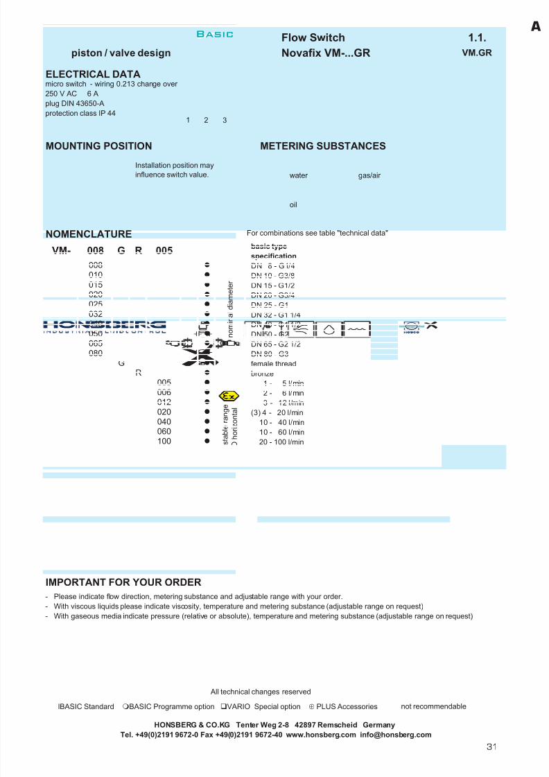
Flow Switch 1.1.piston / valve design Novafix VM-...GR VM.GR
GENERAL CHARACTERISTICS Female thread G1/4 to G3 bronze
TECHNICAL DATA
Adjustable range is indicated for horizontally decreasing flow.
tolerance ±5% of full scalemedia temperature max. 90°Caverage pressure loss 0.25 bar at Qmax.hysteresis depending on switch value
minimum 0.6 l/min.
MATERIALS
housing bronze Rg5/Rg6 nickel platedpiston brass Ms58spring stainless steel 1.4310piston guide brass Ms58seal NBRmagnet bariumferritecap ABS
G 1/2G 3/4G 1
G 3
G 1 1/4G 1 1/2G 2G 2 1/2 16
VM-015GR...
180
10025 40 50
480
30
50 - 400195 148VM-080GR600 100720 100 - 600
2911
AFmm
13
23
73
7.0
12
29 1229 12
3241
1.5
3.0
1442 - 6 3 - 12
10 - 40
15615520 - 100
87
4 - 20
50 - 25030 - 150
1442 - 6
14410 - 60
1444 - 12
68
98
68
weightkg
1.21.31.4
Xmm
2.31.7
113 5952 13
14
5.8137160
1648572
261954.317
b r o n z e / b r a s s
VM-050GR250VM-040GR150VM-032GR100VM-025GR060VM-020GR...
16
701625
120
16 30016
VM-065GR400
15
68
adjustable rangel/min H2O
8 15
Hmm
1441 - 5 3 - 12
Qmax. recom.l/min H2O
Lmm
PNbar
G Type
100100
Mechanical Flow Switch for liquids or gaseous media, withcontactless triggering of an adjustable micro switch.Rugged design in bronze.
good repeatability
dirt-resistanthigh switch capabilityexact setting of switch via scale
VM-010GR...VM-008GR...G 1/4
G 3/8
VM-020GR040
10 15
HONSBERG & CO.KG Tenter Weg 2-8 42897 Remscheid GermanyTel. +49(0)2191 9672-0 Fax +49(0)2191 9672-40 www.honsberg.com [email protected]
250
200
150
100
50
20° 180°140°120°80°
Flow volume H O, 20°CQ (l/min)
Switchposition, tolerance ±10%
50-250 l/min
30-150 l/min
20-100 l/min
10- 60l /min
2
10- 40l /min
Basic
30
7/22/2019 General Honsberg
http://slidepdf.com/reader/full/general-honsberg 33/347
Flow Switch 1.1.piston / valve design Novafix VM-...GR VM.GR
ELECTRICAL DATAmicro switch - wiring 0.213 change over 250 V AC 6 Aplug DIN 43650-Aprotection class IP 44
MOUNTING POSITION METERING SUBSTANCES
water gas/air
oil
NOMENCLATURE For combinations see table "technical data"
basic typespecificationDN 8 - G1/4DN 10 - G3/8DN 15 - G1/2DN 20 - G3/4DN 25 - G1DN 32 - G1 1/4DN 40 - G1 1/2DN 50 - G2DN 65 - G2 1/2DN 80 - G3female threadbronze
1 - 5 l/min2 - 6 l/min3 - 12 l/min
(3) 4 - 20 l/min10 - 40 l/min10 - 60 l/min20 - 100 l/min30 - 150 l/min50 - 250 l/min50 - 400 l/min
100 - 600 l/min
signal lamptemperature indicator 0-120°Cprotection class IP 65material certificationsetting / adjustable ranges for oil or gasgold-plated micro switchtemperature up to 150°C
IMPORTANT FOR YOUR ORDER- Please indicate flow direction, metering substance and adjustable range with your order.- With viscous liquids please indicate viscosity, temperature and metering substance (adjustable range on request)- With gaseous media indicate pressure (relative or absolute), temperature and metering substance (adjustable range on request)
All technical changes reserved
lBASIC Standard BASIC Programme option VARIO Special option ⊕ PLUS Accessories not recommendable
HONSBERG & CO.KG Tenter Weg 2-8 42897 Remscheid GermanyTel. +49(0)2191 9672-0 Fax +49(0)2191 9672-40 www.honsberg.com [email protected]
switch ATEX (product information 92.1.V2 and 92.1.V3)
020
a d j u s t a b l e r a n g e
H 2
O h o r i z o n t a l
Installation position mayinfluence switch value.
BASIC
A
n o m i n a l d i a m e t e r
G
012
100
040
006005
060
R
400
150
VM- 008008
005R
015020025032
010
080
050065
040
G
Programme option
600
VARIO
250
Special option
1 2 3
BasicA
31
7/22/2019 General Honsberg
http://slidepdf.com/reader/full/general-honsberg 34/347
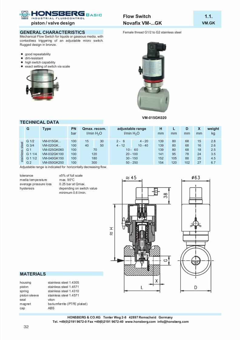
Flow Switch 1.1.piston / valve design Novafix VM-...GK VM.GK
GENERAL CHARACTERISTICS Female thread G1/2 to G2 stainless steel
TECHNICAL DATA
Adjustable range is indicated for horizontally decreasing flow.
tolerance ±5% of full scalemedia temperature max. 90°Caverage pressure loss 0.25 bar at Qmax.hysteresis depending on switch value
minimum 0.6 l/min.
MATERIALS
housing stainless steel 1.4305piston stainless steel 1.4571spring stainless steel 1.4310piston sleeve stainless steel 1.4571seal vitonmagnet bariumferrite (PTFE plated)cap ABS
HONSBERG & CO.KG Tenter Weg 2-8 42897 Remscheid GermanyTel. +49(0)2191 9672-0 Fax +49(0)2191 9672-40 www.honsberg.com [email protected]
Mechanical Flow Switch for liquids or gaseous media, withcontactless triggering of an adjustable micro switch.Rugged design in bronze.
good repeatability
dirt-resistanthigh switch capabilityexact setting of switch via scale
G 3/4G 1/2
G
VM-015GK...VM-020GK...
Type
100
PNbar
10 - 40
VM-015GK020
Hmm
Lmm
139
adjustable rangel/min H2O
80
Qmax. recom.l/min H2O
G 1 1/4
G 2VM-040GK150VM-050GK250
100VM-025GK060VM-032GK100 141
s t a i n l e s s s t e e l
7040 50 4 - 12
100
weightkg
2.62.53.5
10078
10 - 6020 - 10030 - 150
95120152
80139 18100
Dmm
Xmm
68 1668
27G 1 1/2
G 1
6.7
2488 25102
4.5
68100
105
139 80
154 120180
15 2.8
300 50 - 250
15 30 2 - 6 4 - 20
Basic
32

7/22/2019 General Honsberg
http://slidepdf.com/reader/full/general-honsberg 35/347
Flow Switch 1.1.piston / valve design Novafix VM-...GK VM.GK
ELECTRICAL DATAmicro switch - wiring 0.213 change over 250 V AC 6 Aplug DIN 43650-Aprotection class IP 44
MOUNTING POSITION METERING SUBSTANCES
water gas/air
oil aggressive liquids
NOMENCLATURE For combinations see table "technical data"
basic typespecificationDN 15 - G1/2DN 20 - G3/4DN 25 - G1DN 32 - G1 1/4DN 40 - G1 1/2DN 50 - G2female threadhousing stainless steel
2 - 6 l/min4 - 12 l/min4 - 20 l/min
10 - 40 l/min10 - 60 l/min20 - 100 l/min30 - 150 l/min50 - 250 l/min
signal lamptemperature indicator 0-120°Cprotection class IP 65material certificationsetting / adjustable ranges for oil or gasgold-plated micro switchtemperature up to 150°C
IMPORTANT FOR YOUR ORDER- Please indicate flow direction, metering substance and adjustable range with your order.- With viscous liquids please indicate viscosity, temperature and metering substance (adjustable range on request)- With gaseous media indicate pressure (relative or absolute), temperature and metering substance (adjustable range on request)
All technical changes reserved
BASIC Standard BASIC Programme option VARIO Special option ⊕ PLUS Accessories not recommendable
HONSBERG & CO.KG Tenter Weg 2-8 42897 Remscheid GermanyTel. +49(0)2191 9672-0 Fax +49(0)2191 9672-40 www.honsberg.com [email protected]
switch ATEX (product information 92.1.V2 and 92.1.V3)
VARIOSpecial option
Programme optionBASIC
A
100
VM- 015 G
020025032
KG
Installation position mayinfluence switch value.
n o m i n a l d i a m e t e
006
040
K
006
250 a d j u s t a b l e r a n g e
H 2
O h o r i z o n t a l
015
050
012
040060
020
150
1 2 3
BasicA
33

7/22/2019 General Honsberg
http://slidepdf.com/reader/full/general-honsberg 36/347
Flow Switch 1.1.piston / valve design Novafix VDO-...GR VDO.GR
GENERAL CHARACTERISTICS Female thread G1/4 to G3 bronze
TECHNICAL DATA
Adjustable range is indicated for horizontally decreasing flow.
tolerance ±5% of full scalemedia temperature max. 120°Caverage pressure loss 0.5 bar at Qmax.hysteresis depending on switch value
minimum 0.5 l/min.
scale increments
MATERIALS
housing bronze Rg5/Rg6 nickel platedpiston Ms58spring stainless steel 1.4310piston guide brass Ms58seal NBRmagnet bariumferritecap ABStube acrylic (XT)
600
10 - 40
720
137
148
195
180 - 330
30 - 100
400 - 600 100160
203224224
16
100VDO-015GR...
85
2520 30
6040
16
b r o n z e / b r a s s G 1/2
G 1G 1 1/4
G 1/4
7.8
1726
4.25.8
23
G 2G 2 1/2G 3
1616
G 1 1/2 16
VDO-065GR...
G 3/8 100
adjustable rangel/min H2O
programmeoption
standard
2 - 102 - 10
100VDO-008GR010VDO-010GR010
G 3/4
VDO-080GR...
VDO-020GR...VDO-025GR...VDO-032GR...VDO-040GR...
15
25
113
87190 98
2 - 10
100
10 - 4020 - 60
525972
4 - 20
20 - 60
29293241
weightkg
183183 68
68
Hmm
1268 1.3
1.3
2.9
13 1.4
2.21314
1.51.7
1112
150
475
184188
1458560
Mechanical Flow Switch for liquids or gaseous media, withcontactless triggering of an adjustable reed switch.Rugged design in brass / bronze combination.
control and indication
good repeatabilitydirt-resistantalso for dark and/or contaminated liquidsno pressurized or wetted glass partsexact setting of switch via scale
Lmm
15
G Qmax. recom.l/min H2O
PNbar
Type
VDO-015GR010
50 - 150100 - 200180 - 330
VDO-050GR...220290
400250
30 - 100
100 - 200
AFmm
Xmm
30 - 100
73
12
4 - 20
183 29
HONSBERG & CO.KG Tenter Weg 2-8 42897 Remscheid GermanyTel. +49(0)2191 9672-0 Fax +49(0)2191 9672-40 www.honsberg.com [email protected]
Basic
34

7/22/2019 General Honsberg
http://slidepdf.com/reader/full/general-honsberg 37/347
Flow Switch 1.1.piston / valve design Novafix VDO-...GR VDO.GR
ELECTRICAL DATAreed switch - wiring 0.213 change over 250 V AC 1.5 A 50 VAplug DIN 43650-Aprotection class IP 44
MOUNTING POSITION METERING SUBSTANCES
water gas/air
oil
NOMENCLATURE For combination see table "technical data"
basic typespecificationDN 8 - G1/4DN 10 - G3/8DN 15 - G1/2DN 20 - G3/4DN 25 - G1DN 32 - G1 1/4DN 40 - G1 1/2DN 50 - G2DN 65 - G2 1/2DN 80 - G3female threadbronze
2 - 10 l/min4 - 20 l/min
10 - 40 l/min20 - 60 l/min30 - 100 l/min50 - 150 l/min
100 - 200 l/min180 - 330 l/min400 - 600 l/minsignal lamptemperature indicator 0-120°Cprotection class IP 65material certificationflange version in cast iron/bronze/cast steel or stainless steelsetting / adjustable ranges for oil or gasselected hysteresisrhodium contacttemperature control 30-95°Cwetted parts in brass or stainless steeltemperature up to +150°Cdamping for gas control
IMPORTANT FOR YOUR ORDER- Please indicate flow direction, metering substance and adjustable range with your order.- With viscous liquids please indicate viscosity, temperature and metering substance (adjustable range on request)- With gaseous media indicate pressure (relative or absolute), temperature and metering substance (adjustable range on request)
All technical changes reserved
BASIC Standard BASIC Programme option VARIO Special option ⊕ PLUS Accessories not recommendable
HONSBERG & CO.KG Tenter Weg 2-8 42897 Remscheid GermanyTel. +49(0)2191 9672-0 Fax +49(0)2191 9672-40 www.honsberg.com [email protected]
n o m i n a l d i a m e t e r
a d j u s t a b l e r a n g e
H 2
O h o r i z o n t a l
200
020
600
040060100150
330
010R
RG
G
Installation position mayinfluence switch value.
VDO- 008008
040
020025032
010015
065
010
050
080
VARIO
BASIC
Special option
Programme option
1 2 3
BasicA
35

7/22/2019 General Honsberg
http://slidepdf.com/reader/full/general-honsberg 38/347
Flow Switch 1.1.piston / valve design Novafix MXR-...GR MXR.GR
GENERAL CHARACTERISTICS female thread G1/4 to G3 bronze
TECHNICAL DATA
Adjustable range is indicated for horizontally decreasing flow.
tolerance ±10% of full scalemedia temperature max. 160°Caverage pressure loss 0.7 bar at Qmax.
MATERIALS
housing bronze Rg5/Rg6 nickel platedpiston stainless steel 1.4305spring stainless steel 1.4310piston guide stainless steel 1.4305seal Kalrez / Viton
HONSBERG & CO.KG Tenter Weg 2-8 42897 Remscheid GermanyTel. +49(0)2191 9672-0 Fax +49(0)2191 9672-40 www.honsberg.com [email protected]
MXR-025GR100
MXR-010GR...
25
PNbar
100100
Hmm
194194 68
weightkg
1.11.1
SWmm
2929
Xmm
1212
Lmm
68
MXR-015GR...
Compressive load
G 1 MXR-025GR...MXR-020GR...G 3/4
1.4198 8720 - 10025
1.11.2
1020
10 - 40
2.5 - 105 - 20
40 19429
1.5 - 6
adjustable rangel/min H2O
100MXR-008GR...
Type Qmax. recom.l/min H2O
The flow switches type MXR are employed for themonitoring of liquids in temperature ranges of 160°C. Theinstruments operate according to the proven pistonsystem. In a no flow situation the piston rests in the valueseat and will be dislocated relevant to the flow rate. Thismovement is linear magnetically to an externally arrangedswitch unit. Due to the distance between flow and switcharea the sensitive electrical components are seeing only70°C max. with liquid temperature of 160°C max.
media temperature 160°C
6
b r o n z e
60
G
G 1/4G 3/8G 1/2
73194 68 13
1112
3241
bar 100%
80%
60%
40%
0 50 100 150 200 °C
Basic
36

7/22/2019 General Honsberg
http://slidepdf.com/reader/full/general-honsberg 39/347
Flow Switch 1.1.piston / valve design Novafix MXR-...GR MXR.GR
ELECTRICAL DATAreed switschwiring 0.212 n.o.250 V AC 1A 50VAcable 1.5 mprotection class IP 65
MOUNTING POSITION METERING SUBSTANCES
water gas/air
oil
NOMENCLATURE For combination see table "technical data"
basic typespecificationflow switchDN 8 - G1/4DN 10 - G3/8DN 15 - G1/2DN 20 - G3/4DN 25 - G1female threadhousing Rg5/Rg61.5 - 6 l/min2.5 - 10 l/min
5 - 20 l/min10 - 40 l/min20 - 100 l/min
Programme option housing stainless steelBASICSpecial option special cable lengthVARIOIMPORTANT FOR YOUR ORDER- Please indicate flow direction, metering substance and adjustable range with your order.- With viscous liquids please indicate viscosity, temperature and metering substance (adjustable range on request)- With gaseous media indicate pressure (relative or absolute), temperature and metering substance (adjustable range on request)
SPECIAL APPLICATIONS
MXO MXMindicate 20-100% micro switch 230V 6A
option switch head indicate 20-100%
All technical changes reserved
BASIC Standard BASIC Programme option VARIO Special option ⊕ PLUS Accessories not recommendable
Tel. +49(0)2191 9672-0 Fax +49(0)2191 9672-40 www.honsberg.com [email protected] & CO.KG Tenter Weg 2-8 42897 Remscheid Germany
G
010008
015
MXR- 006008MXR-
GR
025020
010
100
020
006
040
R
Installation position may influenceswitch value.
a d j u s t a b l e
r a n g e
H 2
O
h o r i z o n t a l
n o m i n a l
d i a m e t e r
brow n blue
Basic
37
A

7/22/2019 General Honsberg
http://slidepdf.com/reader/full/general-honsberg 40/347
Flow Switch 1.1.piston / valve design Thermoflux TX-...FT TX.FT
GENERAL CHARACTERISTICS Flange DN 15-200 cast steel
TECHNICAL DATA
Adjustable range is indicated for horizontally decreasing flow.
Tolerance ±5% of full scaleMedia temperature max. 350°C Average pressure loss 0.5 bar at Qmax.Hysteresis depending on switch value
minimum 0.3 l/min.
MATERIALS
housing cast steel GSC 25body stainless steel 1.4571piston stainless steel 1.4301 ;
1.4305 ; 1.4571spring stainless steel 1.4310piston sleeve stainless steel 1.4571
seal sigraflex V20011Z3I Face-to-face lenght DIN 3202, series F1viton Flange DIN 2545 PN 40magnet bariumferrite Flange dimension DIN 2501 PN 40tube acrylic (XT) Types of contact faces DIN 2526 Form C
HONSBERG & CO.KG Tenter Weg 2-8 42897 Remscheid GermanyTel. +49(0)2191 9672-0 Fax +49(0)2191 9672-40 www.honsberg.com [email protected]
TX-015FT020K
Mechanical Flow Switch for liquids or gaseous media, withcontactless triggering of an adjustable micro switch.Rugged design in cast steel.
control an indicatingmedia temperature 350°Cgood repeatabilitydirt-resistanthigh switch capabilityDIN flange housing
304040
430450
270400600950
2000TX-100FT...TX-080FT...TX-065FT...
135270
4040
TX-050FT...TX-040FT...
40300 - 450350 - 500
150 - 300200 - 400
410 290 185 145
75380380 180 140 100
kmm
dmm
370 130 95 65 4x14
Hmm
Lmm
Dmm
200 150390 230 165
310
15202532
20
TX-025FT...TX-020FT...TX-015FT...
Qmax. rec.l/min H2O
4040
60
340
100150
5580
4x144x14
8x18
20 - 60 160 115 85370 150 105
10 - 40
4x188x18
4x184x1830 - 100
50 - 200100 - 250 150 - 300
390
PNbar
4040
c a s t s t e e l
80100150
DN Type
40TX-032FT...
200 TX-200FT....40TX-150FT...
405065
87.08x26600 - 750 700 - 950 300 250510 480
weightkg
6.06.58.5
10.513.015.525.531.038.0350
110125
8x22200 160235 190
100 - 250
adjustable rangel/min H2O
20 - 60 30 - 100
10 - 404 - 202 - 8 4 - 20
50 - 200
154.012x30580 600 375 320
Compressive load
1050 - 125040 850 - 10504000
bar 40
30
2010
00 100 200 300 400 °C
Basic
38

7/22/2019 General Honsberg
http://slidepdf.com/reader/full/general-honsberg 41/347
Flow Switch 1.1.piston / valve design Thermoflux TX-...FT TX.FT
ELECTRICAL DATAmicro switch - wiring 0.213 change over 250 V AC 6 Aplug DIN 43650-Aprotection class IP 44
MOUNTING POSITION METERING SUBSTANCES
water gas/air
oil
NOMENCLATURE For combinations see table "technical data"
basic typespecificationDN 15
DN 20DN 25DN 32DN 40DN 50DN 65DN 80DN 100DN 150DN 200flangehousing cast steel
2 - 8 l/min4 - 20 l/min
10 - 40 l/min20 - 60 l/min30 - 100 l/min50 - 200 l/min
100 - 250 l/min150 - 300 l/min200 - 400 l/min300 - 450 l/min350 - 500 l/min600 - 750 l/min700 - 950 l/min850 - 1050 l/min
1050 - 1250 l/minplug DIN 43650-A
cable gland Pg9 with 2.5 metre cable and TÜV-approval TÜV.SW.02-021housing stainless steel
IMPORTANT FOR YOUR ORDER- Please indicate flow direction, metering substance and adjustable range with your order.- With viscous liquids please indicate viscosity, temperature and metering substance (adjustable range on request)- With gaseous media indicate pressure (relative or absolute), temperature and metering substance (adjustable range on request)
All technical changes reserved
BASIC Standard BASIC Programme option VARIO Special option ⊕ PLUS Accessories not recommendable
HONSBERG & CO.KG Tenter Weg 2-8 42897 Remscheid GermanyTel. +49(0)2191 9672-0 Fax +49(0)2191 9672-40 www.honsberg.com [email protected]
K
B1250
B
150
065
950
400450500750
080100
300250
1050
Programme optionen BASIC
T
020025032040050
TX- 015015
n o m i n a l d i a m e t e r
F 008
060100200
008
040
020
TF
200
Installation position mayinfluence switch value.
a d j u s t a b l e r a n g e
H 2
O h o r i z o n t a l
1 2 3
Basic
39
A

7/22/2019 General Honsberg
http://slidepdf.com/reader/full/general-honsberg 42/347
Flow Indicator 1.2.piston / valve design Visoflow MP-...GR MP.GR
GENERAL CHARACTERISTICS Female thread G1/4 to G3 bronze
TECHNICAL DATA
Indicating range is calibrated for vertical upward increasing flow.
tolerance ±10% of full scalemedia temperature max. 100°Caverage pressure loss 0.7bar at Qmax.
MATERIALS
housing bronze Rg5/Rg6 nickel platedpiston brass Ms58spring stainless steel 1.4310piston guide brass Ms58tube acrylic (XT)
HONSBERG & CO.KG Tenter Weg 2-8 42897 Remscheid GermanyTel. +49(0)2191 9672-0 Fax +49(0)2191 9672-40 www.honsberg.com [email protected]
Mechanical Flow Indicator for liquids or gaseous media,with spring-supported piston. Piston is magnetically linkedto an indicator element. Rugged design in bronze / brasscombination.
good repeatabiltydirt resistancefor dark and/or contaminated liquidsturnable scaleno pressurized or wetted glass parts
4060
Qmax. recom.l/min H2O
b r o n z e / b r a s s
1020
150
600
1 = 100% = 20l/min
1.42.02.6
98113
87
1459
136150
40016 50 - 25030 - 150
30 - 150
80 - 40050 - 250
2932
100 134152
10 - 40 2.5 - 10 5 - 2020 - 100
2617
131112
7313310 - 40 5 - 205 - 20 1.5 - 6
2.5 - 10
120 - 600 80 - 400
250
1.11.2
15472
16184 137 4.2
indication scale
5.68.3200
85148 23100
200 16016
G 3 16MP-080GR...
2516
G
G 1/4G 3/8G 1/2
MP-008GR...
Type
MP-015GR...25
12 - 60
weightkg
1.11.1
2929
1212
Xmm
AFmm
6 10Standard Programme option1.5 - 6
PNbar
100100100
130
Lmm
2.5 - 10
2.5 - 10 68130130
G 1G 1 1/4G 1 1/2
MP-015GR020
indicating rangel/min H2O
Hmm
2.5 - 10 1.5 - 66868MP-010GR...
G 2G 2 1/2
MP-040GR150MP-032GR...MP-025GR...MP-020GR...
MP-065GR...MP-050GR...
G 3/4
Basic
40

7/22/2019 General Honsberg
http://slidepdf.com/reader/full/general-honsberg 43/347
Flow Indicator 1.2.piston / valve design Visoflow MP-...GR MP.GR
ELECTRICAL DATA
No electrical components
MOUNTING POSITION METERING SUBSTANCES
water gas/air
oil
NOMENCLATURE For combination see table "technical data"
basic typespecificationDN 8 - G1/4DN 10 - G3/8DN 15 - G1/2DN 20 - G3/4DN 25 - G1DN 32 - G1 1/4DN 40 - G1 1/2DN 50 - G2DN 65 - G2 1/2DN 80 - G3female threadhousing bronze1.5 - 6 l/min2.5 - 10 l/min
5 - 20 l/min10 - 40 l/min12 - 60 l/min20 - 100 l/min30 - 150 l/min50 - 250 l/min80 - 400 l/min
120 - 600 l/minProgramme option housing stainless steelBASICSpecial option special rangeVARIO special scales
IMPORTANT FOR YOUR ORDER- Please indicate flow direction, metering substance and indicating range with your order.- With viscous liquids please indicate viscosity, temperature and metering substance (indicating range on request)- With gaseous media indicate pressure (relative or absolute), temperature and metering substance (indicating range on request)
All technical changes reserved
lBASIC Standard BASIC Programme option VARIO Special option ⊕ PLUS Accessories not recommendable
Installation position may influenceindicating range.
100
/
/
i n d i c a t i n g r a n g e
H 2
O h o r i z o n t a l
600400
/
/
/
060040
006010
/
/
006
020
065
040050
020025
008008
015
032
n o m i n a l d i a m e t e r
G R
080
MP-
GR
010
250150
HONSBERG & CO.KG Tenter Weg 2-8 42897 Remscheid GermanyTel. +49(0)2191 9672-0 Fax +49(0)2191 9672-40 www.honsberg.com [email protected]
Basic
41
A

7/22/2019 General Honsberg
http://slidepdf.com/reader/full/general-honsberg 44/347
Flowmeter 1.3.piston / valve design Novatron TZ1-...GR TZ1.GR
GENERAL CHARACTERISTICS Female thread G1/4 to G3 bronze
TECHNICAL DATA
Metering range is indicated for horizontally increasing flow.
tolerance ±3% of full scalemedia temperature max. 90°Caverage pressure loss 0.25bar at Qmax.
MATERIALS
housing bronze Rg5/Rg6 nickel platedpiston/disc brass Ms58
spring stainless steel 1.4310piston sleeve brass Ms58magnet bariumferriteseal NBR
HONSBERG & CO.KG Tenter Weg 2-8 42897 Remscheid GermanyTel. +49(0)2191 9672-0 Fax +49(0)2191 9672-40 www.honsberg.com [email protected]
TZ1-025GR060TZ1-020GR...TZ1-015GR...
16TZ1-032GR100
16
1616
2525
G 2
G 3 TZ1-080GR600TZ1-065GR400TZ1-050GR250
TZ1-025GR060
212216
7387
Hmm
4 - 20 212
3 - 123 - 12
G 1 1/220 - 25030 - 400 160
137268G 2 1/2
G
G 1/4G 3/8
G 1 1/4
10026840016250
TZ1-040GR150
68
2 - 62 - 6
1.72.02.63.1
weightkg
1.61.61.6
26851772
2 - 6
6868100 10
100
100 21221212
Qmax. rec.l/min H2O
8 12
Type PNbar
Xmm
AFmm
metering rangel/min H2O
Lmm
32415259
1212
2929
b r o n z e / b r a s s
TZ1-010GR...TZ1-008GR...
G 1/2G 3/4G 1
2040
600
150
30 - 600
4 - 20 10 - 4010 - 60
10 - 15010 - 100
6.47.5
228
60100
11398226
14236
Mechanical Flowmeter for liquids or gaseous media. Withmagnetic triggering of a metering unit with 270° of pointer range. Rugged design in bronze/brasscombination.
local meteringgood repeatabilitydirt-resistantlow pressure losseasy adjustment by indicating pointer
8.7
29
148 23
13111213
Basic
42

7/22/2019 General Honsberg
http://slidepdf.com/reader/full/general-honsberg 45/347
Flowmeter 1.3.piston / valve design Novatron TZ1-...GR TZ1.GR
ELECTRICAL DATA
No electrical components. integrated micro switchwith front switch unitssee data sheet 1.3.TZ1.ZE
INSTALLATION POSITIONS METERING SUBSTANCES
water gas/air
oil
NOMENCLATURE For combinations see table "technical data".
basic typespecificationFlowmeter Flowmeter with integrated micro switchDN 8 - G1/4DN 10 - G3/8DN 15 - G1/2DN 20 - G3/4DN 25 - G1DN 32 - G1 1/4DN 40 - G1 1/2DN 50 - G2DN 65 - G2 1/2DN 80 - G3female threadhousing bronze
2 - 6 l/min3 - 12 l/min4 - 20 l/min
10 - 40 l/min10 - 60 l/min10 - 100 l/min10 - 150 l/min20 - 250 l/min30 - 400 l/min30 - 600 l/minfront switch unit with 10-kOhm-potentiometer
BASIC diodespecial range
VARIO metering range for oil or gasfront switch unit 2pol, n.o. or n.c.
IMPORTANT FOR YOUR ORDER- Please indicate flow direction, metering substance and metering range with your order.- With viscous liquids please indicate viscosity, temperature and metering substance (metering range on request)- With gaseous media indicate pressure (relative or absolute), temperature and metering substance (metering range on request)- For additional information concerning options micro switch and front switch see data sheet 1.3.TZ1.ZE.
All technical changes reserved
lBASIC Standard BASIC Programme option VARIO Special option ⊕ PLUS Accessories not recommendable
HONSBERG & CO.KG Tenter Weg 2-8 42897 Remscheid GermanyTel. +49(0)2191 9672-0 Fax +49(0)2191 9672-40 www.honsberg.com [email protected]
Installation position mayinfluence metering range.
050065
BASIC Programme option
400
100060
006
BASIC Standard
m e t e r i n g r a n g e
H 2
O h o r i z o n t a l
012020040
150250
600
TZ1- 008 G R
Special option
006
020
010015
008
025032040
080G
R
Programme option
n o m i n a l d i a m e t e r
TZ1-TZ1M-
Basic
43
A

7/22/2019 General Honsberg
http://slidepdf.com/reader/full/general-honsberg 46/347
Flowmeter 1.3.piston / valve design Novatron TZ1-...GK TZ1.GK
GENERAL CHARACTERISTICS Female thread G1/2 to G2 stainless steel
TECHNICAL DATA
Metering range is indicated for horizontally increasing flow.
tolerance ±3% of full scalemedia temperature max. 90°Caverage pressure loss 0.25bar at Qmax.
MATERIALS
housing stainless steel 1.4305piston/disc stainless steel 1.4571spring stainless steel 1.4310piston sleeve stainless steel 1.4571magnet bariumferrite (PTFE plated)seal viton
HONSBERG & CO.KG Tenter Weg 2-8 42897 Remscheid GermanyTel. +49(0)2191 9672-0 Fax +49(0)2191 9672-40 www.honsberg.com [email protected]
G
G 1/2G 3/4G 1G 1 1/4G 1 1/2G 2
10 - 150
Type
TZ1-015GK...TZ1-020GK...TZ1-025GK060
100
100100
4060
100TZ1-032GK100TZ1-040GK150TZ1-050GK250 102
68 15
Lmm
210
105210
210
metering rangel/min H2O
6868
80
225
210100
weightkg
2.82.7
Xmm
1618
2.94 - 20 5 - 40
3.43.825
78 2410 - 6010 - 100
Qmax. rec.l/min H2O
2 - 620 4 - 20
Dmm
s t a i n l e s s t e e l
10088
250 20 - 250 120223
95
PNbar
5.127
TZ1-015GK006
100
150
8080
Hmm
Mechanical Flowmeter for liquids or gaseous media. Withmagnetic triggering of a metering unit with 270° of pointer range. Rugged design in stainless steel.
local metering
good repeatabilitydirt-resistantlow pressure losseasy adjustment by indicating pointer
Basic
44

7/22/2019 General Honsberg
http://slidepdf.com/reader/full/general-honsberg 47/347
Flowmeter 1.3.piston / valve design Novatron TZ1-...GK TZ1.GK
ELECTRICAL DATA
No electrical components. integrated micro switchwith front switch unitssee data sheet 1.3.TZ1.ZE
INSTALLATION POSITIONS METERING SUBSTANCES
water gas/air
oil aggressive liquids
NOMENCLATURE For combinations see table "technical data".
basic typespecificationFlowmeter Flowmeter with integrated micro switchDN 15 - G1/2DN 20 - G3/4DN 25 - G1DN 32 - G1 1/4DN 40 - G1 1/2DN 50 - G2female threadhousing stainless steel
2 - 6 l/min4 - 20 l/min5 - 40 l/min
10 - 60 l/min10 - 100 l/min10 - 150 l/min20 - 250 l/minfront switch unit with 10-kOhm-potentiometer
BASIC diodespecial range
VARIO metering range for oil or gasfront switch unit 2pol, n.o. or n.c.
IMPORTANT FOR YOUR ORDER- Please indicate flow direction, metering substance and metering range with your order.- With viscous liquids please indicate viscosity, temperature and metering substance (metering range on request)- With gaseous media indicate pressure (relative or absolute), temperature and metering substance (metering range on request)- For additional information concerning options micro switch and front switch see data sheet 1.3.TZ1.ZE.
All technical changes reserved
BASIC Standard BASIC Programme option VARIO Special option ⊕ PLUS Accessories not recommendable
m e t e r i n g r a n g e
H 2 O
h o r i z o n t a l
HONSBERG & CO.KG Tenter Weg 2-8 42897 Remscheid GermanyTel. +49(0)2191 9672-0 Fax +49(0)2191 9672-40 www.honsberg.com [email protected]
100
020040060
n o m i n a l d i a015
BASIC Standard BASIC Programme option
020025
040032
Special option
G050
K006
250150
Programme option
TZ1-TZ1M-
Installation position mayinfluence metering range.
TZ1- 015 G K 006
Basic
45
A

7/22/2019 General Honsberg
http://slidepdf.com/reader/full/general-honsberg 48/347
Additional features 1.3.for Novatron TZ1- TZ1.ZE
OPTION
wiring 0.342 change over 250 V AC 5 A
plug DIN 43650-Aprotection class IP 65
wiring 0.269
50 V DC 100 mA 1.5 Wresistance max. 10 k Ω
additional tolerance ±3 %resistance tolerance ±1 %linearity ±0.3 %plug Hirschmann G4protection class IP 60
wiring 0.268250 V AC 0.6 A 50 VAplug Hirschmann G4protection class IP 60
wiring 0.285250 V AC 0.6 A 50 VAplug Hirschmann G4protection class IP 60
All technical changes reserved
lBASIC Standard BASIC Programme option VARIO Special option ⊕ PLUS Accessories not recommendable
TZ1P- front switch unit with 10-kOhm- potentiometer
TZ1M- integrated micro switch
TZ1M2- switch unit with 2pole n.o.
TZ1M3- switch unit with 2pole n.c.
HONSBERG & CO.KG Tenter Weg 2-8 42897 Remscheid GermanyTel. +49(0)2191 9672-0 Fax +49(0)2191 9672-40 www.honsberg.com [email protected]
1 2 3
1.switch 2.switch
1 2 3
1.switch 2.switch
1 3 2
3 1 2
Basic
46

7/22/2019 General Honsberg
http://slidepdf.com/reader/full/general-honsberg 49/347
A
Special applications
Flow control instruments PD-...TH, PD-...MH, PD-...FH
PVC for aggressive media, non-compatible for metal materials
Mechanical flow control instru-ment for liquid or gaseousmedia, with non-contact trigger-ing of an adjustable reed con-
tact. Sturdy construction madeof PVC.
l Adhesive fitting DN 15-80
Adhesive stub-connectionDN 15-50
Flange DN 15-80l Reed switchl Ranges from 2-500 l/min
l Pressure rating PN 10l Max. temperature 60 °Cl PVC material
Flow control instruments VD-...FR, VD-...FG, VD-...FT, VD-...FK
Flange version for process or large nominal diameters
Mechanical flow control instru-ment for liquid or gaseousmedia, with non-contact trigger-ing of an adjustable reed con-
tact. Sturdy construction madeof cast iron.
l Flange DN 15-300[stainless steel DN 15-150]l Reed switchl Ranges from 2-1600 l/minl Pressure rating PN 16-40l Max. temperature 120 °Cl Red bronze, cast iron,
cast steel or stainless steelmaterial
Flow control instruments VM-...FG
Flange version for process or large nominal diameters
Mechanical flow control instru-ment for liquid or gaseousmedia, with non-contact trigge-ring of an adjustable micro-switch. Sturdy constructionmade of cast iron.
l Flange DN 15-200l Micro-switchl Ranges from 5-4000 l/minl Pressure rating PN 16l Max. temperature 90 °Cl Cast iron material
47

7/22/2019 General Honsberg
http://slidepdf.com/reader/full/general-honsberg 50/347

7/22/2019 General Honsberg
http://slidepdf.com/reader/full/general-honsberg 51/347
l Complete separation of electrical Õ maintenance advantageand hydraulic component
l Switch selection by helix Õ accurate settingarrangement and scale
l Metal piston and protected Õ rugged design for
twin magnet critical applicationl Spring supported piston Õ optional installation
l Valve housing Õ low pressure loss
Why to use a valve piston instrumentBasic
49

7/22/2019 General Honsberg
http://slidepdf.com/reader/full/general-honsberg 52/347
Market segments
Application
l Power plantl Machine toolsl Welding technology l Gearsl Heat transfer
installationl Pumps
l Providing reliable flow situation in cooling systeml Controlling the emulsion supply for high performance toolsl Creating alarm in case of failures or drop of oil feed into gear
boxesl Running dry protection of pumps
Where to use a valve piston instrument
Honsberg & Co. KGTenter Weg 2-8 · 42897 Remscheid · GermanyP.O. Box 1103 69 · 42863 Remscheid · GermanyTel. +49(0)2191 9672-0 · Fax +49(0)2191 9672-40www.honsberg.com · [email protected]
50
Basic

7/22/2019 General Honsberg
http://slidepdf.com/reader/full/general-honsberg 53/347

7/22/2019 General Honsberg
http://slidepdf.com/reader/full/general-honsberg 54/347
Honsberg & Co. KGTenter Weg 2-8 · 42897 Remscheid · GermanyP.O. Box 1103 69 · 42863 Remscheid · GermanyTel. +49(0)2191 9672-0 · Fax +49(0)2191 9672-40www.honsberg.com · [email protected]
Basic
52
System description
Device systemThe piston system inline design is used for monitoring and indicatingliquid and gaseous metering materials. A magnet-equipped and spring-supported piston moves in a linear-shaped body and is moved in thedirection of flow by the flowing medium, whereby the path of the pistonis directly proportional to the flow rate. Since the piston is spring-supported, the devices can be installed in any position and reset safelywhen the volume flow diminishes.
Function and advantages
The inline design of the devices makes a block assembly possible,where the body is manufactured from solid material and can thuswithstand extremely high pressure loads. The switches are arrangedoutside the body. This feature provides advantages in particular withrespect to the high pressure range or installations where compact dimensions are mandatory.
The switch units are horizontally adjustable and some are moved viapinion and scale [HD1K, HD1KV] which makes extremely accuratedevice setting possible. Thanks to the adjustment, a device workingrange of up to 1:10 is achieved.
In case of an indication function, the primary piston is coupled tometering or indicating equipment which displays the current flow in
this way. The display units are front faced or lateral mounted.
The new display designs for Honsberginline piston meters
The uniform casing of the display unit allows for mounting on the sideor front.
l Easy to mount l Touchless needle couplingl Good readabilityl Mounting on the front or side
A simplified version of the MR1KJ display comes as a 10 -100 %magnet display.
no flow
flow
side display O1
front display Z1
display 10 -100 % M1J
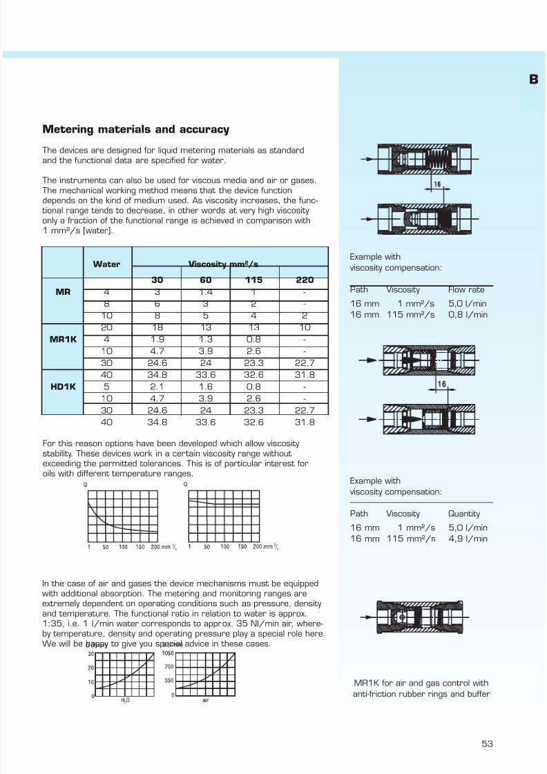
7/22/2019 General Honsberg
http://slidepdf.com/reader/full/general-honsberg 55/347
53
Metering materials and accuracy The devices are designed for liquid metering materials as standardand the functional data are specified for water.
The instruments can also be used for viscous media and air or gases.The mechanical working method means that the device functiondepends on the kind of medium used. As viscosity increases, the func-
tional range tends to decrease, in other words at very high viscosityonly a fraction of the functional range is achieved in comparison with1 mm²/s [water].
For this reason options have been developed which allow viscositystability. These devices work in a certain viscosity range without exceeding the permitted tolerances. This is of particular interest foroils with different temperature ranges.
In the case of air and gases the device mechanisms must be equippedwith additional absorption. The metering and monitoring ranges areextremely dependent on operating conditions such as pressure, densityand temperature. The functional ratio in relation to water is approx.1:35, i.e. 1 l/min water corresponds to approx. 35 Nl/min air, where-by temperature, density and operating pressure play a special role here.We will be happy to give you special advice in these cases.
Water Viscosity mm²/s
30 60 115 220MR 4 3 1.4 1 -
8 6 3 2 -10 8 5 4 220 18 13 13 10
MR1K 4 1.9 1.3 0.8 -10 4.7 3.9 2.6 -30 24.6 24 23.3 22.740 34.8 33.6 32.6 31.8
HD1K 5 2.1 1.6 0.8 -10 4.7 3.9 2.6 -30 24.6 24 23.3 22.740 34.8 33.6 32.6 31.8
Example with
viscosity compensation:
Path Viscosity Flow rate
16 mm 1 mm²/s 5,0 l/min16 mm 115 mm²/s 0,8 l/min
Example with viscosity compensation:
Path Viscosity Quantity
16 mm 1 mm²/s 5,0 l/min
16 mm 115 mm²/s 4,9 l/min
MR1K for air and gas control withanti-friction rubber rings and buffer
B

7/22/2019 General Honsberg
http://slidepdf.com/reader/full/general-honsberg 56/347
Honsberg & Co. KGTenter Weg 2-8 · 42897 Remscheid · GermanyP.O. Box 1103 69 · 42863 Remscheid · GermanyTel. +49(0)2191 9672-0 · Fax +49(0)2191 9672-40www.honsberg.com · [email protected]
Basic
54
Handling and operationIf the switch point needs to be set, this can be done by adjusting theswitching head via a pinion setting [HD1K, HD1KV] or by longitudinaladjustment. When the switching point has been reached, the switchingunit is fixed using an attachment screw.
The Honsberg magnetic displays [NJ, NJV] are mainly used in industryfor non-transparent metering materials and/or higher pressures.
Five-channel manifold with switch support and diodes arranged on thefront. Use of Honsberg valve strips [Type VB 1-8 stations] for separateand compact dosage and monitoring of large-scale gear systems.
NJVK

7/22/2019 General Honsberg
http://slidepdf.com/reader/full/general-honsberg 57/347
55
m i s c e l l a n e o u s
p a g e
a g g r e s s
i v e
g a s
/ a
i r
o i l
i n d i c a t i o n
t y p e
c o n t r o
l
c o n n e c t i o n
o u t p u t s i g n a
l
o n s
i t e m e t e r i n g
m a x . p r e s s u r e
b a r
m a x . t e m p e r a t u r e
° C
w a t e r
n o m
i n a
l d i a m e t e r
l standard m standard option special option all data sheets available under www.honsberg.com
B
FW1 8 - 25 female thread brass l 10 90 l 3 3 568 - 25 female thread plastic l 100 90 l 3 3
FW3 8 female thread brass l 100 90 l 3 3 58
FX 15 male thread plastic l 10 80 l 3 filter 59
HD1K 8 - 25 female thread brass l m m 200 120 l 3 3 61female thread stainless steel l m m 200 120 l 3 3 3
HD2K 8 - 25 female thread brass l m m 200 120 l 3 64
female thread stainless steell m m
200 120l 3 3
HM1K 8 - 25 female thread brass l m m 200 70 l 3 3 67female thread stainless steel l m m 200 70 l 3 3 3
HR1MV 32 - 50 female thread brass l m m 200 120 l 3 3 70female thread brass l m m 200 120 l 3 3 3
MF 3 female thread brass l 6 80 l 737 female thread brass l 6 80 l 74
MR 8 - 25 female thread brass l m m 200 120 l 3 3 75female thread stainless steel l m m 200 120 l 3 3 3
MR1K 8 - 25 female thread brass l m m 200 120 l 3 3 77female thread stainless steel l m m 200 120 l 3 3 3
RVM 8 female thread brass l 300 100 l 3 79female thread stainless steel l 300 100 l 3 3
NH1 15 female thread stainless steel m l 10 65 l 81
NJ 8 - 25 female thread brass m l 100 100 l 3 3 82female thread stainless steel m l 100 100 l 3 3 3
NJV 8 - 25 female thread brass m l 100 100 l 3 85
MH 8 - 25 female thread aluminium m l 10 65 l 3 3 88
VF 8 female thread brass m l 16 100 l 3 3 90female thread stainless steel m l 16 100 l 3 3 3
VO 15 - 25 female thread brass m l 16 100 l 3 3 92female thread stainless steel m l 16 100 l 3 3 3
NO 8 - 25 female thread brass m l l 50 90 l 3 3 94female thread stainless steel m l l 50 90 l 3 3 3
AR 10 female thread brass l 150 80 l 3 3 96
MI 8 - 25 female thread brass l 16 60 l 3 3 96female thread stainless steel l 16 60 l 3 3 3
OT 15 - 20 male thread brass l 10 100 l 3 3 valve 96
s p e c i a
l a p p
l i c a t i o n
s t a n
d a r d a p p
l i c a t i o n
HONSBERG & CO.KG Tenter Weg 2-8 42897 Remscheid GermanyTel. +49(0)2191 9672-0 Fax +49(0)2191 9672-40 www.honsberg.com [email protected]

7/22/2019 General Honsberg
http://slidepdf.com/reader/full/general-honsberg 58/347
Flow Switch 1.1.piston / inline design Novafix FW1-...GP/GM FW1.
GENERAL CHARACTERISTICS Female thread G1/4 to G1 POM/brass
TECHNICAL DATA
Adjustable range is indicated for horizontally decreasing flow.
tolerance ±10% of full scalemedia temperature max. 90°C FW1-008GM - FW1-010GMaverage pressure loss 0.3 bar at 25 l/minhysteresis depending on the switching
value minimum 0.5 l/min.
FW1-015GP FW1-015GM
FW1-020G. - FW1-025G.MATERIALS
FW1-...GP FW1-...GMhousing POM glass-fibre enforced brass Ms58 nickel platedpiston POM POMspring stainless steel 1.4310 stainless steel 1.4310magnet bariumferrite bariumferriteseals - viton (DN8-10 only)switch head polycarbonate polycarbonate
HONSBERG & CO.KG Tenter Weg 2-8 42897 Remscheid GermanyTel. +49(0)2191 9672-0 Fax +49(0)2191 9672-40 www.honsberg.com [email protected]
0.04
1- 1130 100
258985
30
100 b r a s s
weightkg
P O M
0.130.17-
-18
40
301- 6
G 3/8G 1/2G 3/4G 1
FW1-010GM0060.33
0.72
0.310.28
0.8318-40-
12
18
25 --
36 18
-18
25
85
100FW1-025GM011
AFmm
Xmm
Bmm
adjustable rangel/min H 2O
Hmm
Lmm
100100 89
101- 6
10 2030
FW1-015GP006
8 30
12
1830 100 301- 11
27-36
G 1 FW1-025GP01130
101- 11 100
301- 11
30
1- 61- 6
30100 20
30FW1-020GM011 100
G Type
FW1-008GM006
G 3/4 FW1-020GP011G 1/2
G 1/4
Mechanical Flow Switch for liquid or gaseous media, withspring-supported piston and magnetic triggering of a reedswitch. Rugged design in plastic or brass.
minimal pressure lossgood repeatabilityhigh switch capabilitydirt-resistanthermetic separation of mechanicaland electrical component
FW1-015GM006
PNbar
Qmax. rec.l/min H 2O
10
Basic
56

7/22/2019 General Honsberg
http://slidepdf.com/reader/full/general-honsberg 59/347
Flow Switch 1.1.piston / inline design Novafix FW1-...GP/GM FW1.
ELECTRICAL DATAreed switch - wiring 0.378 n.o.230 V AC 0,5 A 50 VAcontact for locking plug M 12x1, 4-poleprotection class IP 67
MOUNTING POSITION METERING SUBSTANCES
water gas/air
oil
NOMENCLATURE For combination see table "technical data"
basic typespecificationnominal diameter DN 8 - G1/4 (only brass design)nominal diameter DN 10 - G3/8 (only brass design)nominal diameter DN 15 - G1/2nominal diameter DN 20- G3/4nominal diameter DN 25 - G1female threadplastic POMbrassadjustable range 1- 6 l/min horizontal H 2Oadjustable range 1- 11 l/min horizontal H 2Oswitch values for oil or gascable 3 mPN 500 (DN 15)
IMPORTANT FOR YOUR ORDER
- Please indicate flow direction, metering substance and adjustable range with your order.- With viscous liquids please indicate viscosity, temperature and metering substance (adjustable range on request)- With gaseous media indicate pressure (relative or absolute), temperature and metering substance (adjustable range on request)
ACCESSORY
Locking plug M12x1basic typespecificationready-made cableself makable cable 4-polematerial PURlength 2 mlength 5 m
length 10 mmoulded-on plugstraight plugangled plug 90°
All technical changes reserved
BASIC Standard BASIC Programme option VARIO Special option ⊕ PLUS Accessories not recommendable
WG
S100502
PU-
K
KB04K
PU- 02 S
VARIOSpecial option
G
011006
G
MP
008
FW1- 008 G P
010015020025
Installation position mayinfluence switch value.
006
HONSBERG & CO.KG Tenter Weg 2-8 42897 Remscheid GermanyTel. +49(0)2191 9672-0 Fax +49(0)2191 9672-40 www.honsberg.com [email protected]
1brown
2white
3blue
4black
free
Basic
B
57

7/22/2019 General Honsberg
http://slidepdf.com/reader/full/general-honsberg 60/347
flow switch 1.1.piston / inline design Novafix FW3-...GM FW3.
GENERAL CHARACTERISTICS Female thread G1/4 brass
FW3-008GMTECHNICAL DATA
Switch value is indicated for horizontally decreasing flow.
tolerance ±10% of full scalemedia temperature max. 90°C
MATERIALS
housing brass Ms58 nickel platedpiston brass Ms58piston stop POMspring stainless steel 1.4310magnet bariumferriteswitch head polycarbonate
MOUNTING POSITION ELECTRICAL DATAreed switch - wiring 0.378 n.o.230 V AC 0,5 A 50 VAcontact for locking plug M 12x1, 4-poleprotection class IP 67
METERING SUBSTANCES NOMENCLATUREBeispiel
water gas/air Beschreibungfemale thread G 1/4brass design
oil cable 3 m
IMPORTANT FOR YOUR ORDER- Please indicate flow direction, metering substance and adjustable
range with your order.- With gaseous media indicate pressure (relative or absolute),
temperature and metering substance (adjustable range on request)
All technical changes reserved
BASIC Standard BASIC Programme option VARIO Special option ⊕ PLUS Accessories not recommendable
HONSBERG & CO.KG Tenter Weg 2-8 42897 Remscheid GermanyTel. +49(0)2191 9672-0 Fax +49(0)2191 9672-40 www.honsberg.com [email protected]
Mechanical Flow Switch for liquid or gaseous media, withspring-supported piston and magnetic triggering of a reedswitch. Rugged design in plastic or brass..
good repeatabilityhigh switch capabilityhermetic separation of mechanicaland electrical component
Programme option
G
switch value l/min H 2Oselectable range for fixed switcg
008
6 0.4 - 2.5
MG
brass
Installation position mayinfluence switch value.
M
Qmax. recom.l/min
FW3-
PNbar
G1/4
M
100
Type
FW3-008GM 0.25
weightkg
1brown
2white
3blue
4black
free
Basic
58

7/22/2019 General Honsberg
http://slidepdf.com/reader/full/general-honsberg 61/347
Flow Switch 1.1.piston / inline design Fluvafix FX-015AP FX.
GENERAL CHARACTERISTICS Male thread G1/2A POM
FX-015APTECHNICAL DATA
Switch value is indicated for upward decreasing flow.
tolerance ±15% of switch valuemedia temperature max. 80°C at 6 bar average pressure loss FX 0.01 bar at 5 l/min
FXF 0.20 bar at 5 l/minhysteresis depending on the switch
value minimum 0.3 l/min. FX-015AP FXF-015APfilter 25 µm
MATERIALS
FX-015AP FXF-015APbody POM glass-fibre POM glass-fibrepiston brass Ms58 brass Ms58snap ring CuSn8F70 CuSn8F70spring - stainless steel 1.4310magnet bariumferrite bariumferriteseals NBR NBRfilter nylon/POM nylon/POM
HONSBERG & CO.KG Tenter Weg 2-8 42897 Remscheid GermanyTel. +49(0)2191 9672-0 Fax +49(0)2191 9672-40 www.honsberg.com [email protected]
G Type Qmax. recom.l/min H 2O
1210 1210FX-015AP
weightkg
0.152.0 - 12
switch value l/min H 2Oselectable rangefor fixed switch
0.4 - 5 0.14
Mechanical Flow Switch for liquid or gaseous media, withmagnetic triggering of a fixed reed switch. Plastic housingwith integrated filter.
fixed switch valueintegrated filter control of small flow rateshigh switch capabilityflow regulator as option
FXF-015AP
PNbar
(20°C)
G1/2A P O M
Basic
B
59

7/22/2019 General Honsberg
http://slidepdf.com/reader/full/general-honsberg 62/347
Flow Switch 1.1.piston / inline design Fluvafix FX-015AP FX.
ELECTRICAL DATAreed switch - wiring 0.212 n.o.230 V AC 1 A 50 VAcabel 0.5 mprotection class IP 65
MOUNTING POSITION METERING SUBSTANCESFX FXF
water
gas/air
NOMENCLATUREbasic typespecificationFlow SwitchFlow Switch with additional spring supportnominal diameter DN 15male threadplastic designintegrated flow regulator
BASIC
IMPORTANT ORDER DETAILS- Please indicate flow direction, metering substance and switch value with your order.- With gaseous media indicate pressure (relative or absolute), temperatue and metering substance (switch value on request)
OPTIONS
Flow Switch with integrating flow regulator
limiter flow rates 3,5,6,8,10,12 l/min H 2O.tolerance from 2 bars ±15%temperature max. 65°C
All technical changes reserved
lBASIC Standard BASIC Programme option VARIO Special option ⊕ PLUS Accessories not recommendable
Tel. +49(0)2191 9672-0 Fax +49(0)2191 9672-40 www.honsberg.com [email protected]
FX-
Position may influence switchvalue.
HONSBERG & CO.KG Tenter Weg 2-8 42897 Remscheid Germany
015
015
A
Programme option
P
P A
FXF-
FX-
brown blue
Basic
60

7/22/2019 General Honsberg
http://slidepdf.com/reader/full/general-honsberg 63/347
Flow Switch 1.1.piston / inline design Novafix HD1K-...GM/GK HD1K.
GENERAL CHARACTERISTICS Female thread G1/4 - G1 brass/stainless steel
HD1K-020GM040
TECHNICAL DATA
Adjustable range is indicated for horizontally decreasing flow.
tolerance ±5% of full scalemedia temperature max. 120°Caverage pressure loss 0.5 bar at Qmax.hysteresis depending on switch value
minimum 0.7 l/min.
MATERIALS
HD1K-...GM HD1K-...GKbody brass Ms58 stainless steel 1.4571
nickel platedpiston brass Ms58 stainless steel 1.4404spring stainless steel 1.4310 stainless steel 1.4310magnet bariumferrite bariumferrite
PTFE platedseals NBR vitonswitch head polycarbonate polycarbonate
HONSBERG & CO.KG Tenter Weg 2-8 42897 Remscheid GermanyTel. +49(0)2191 9672-0 Fax +49(0)2191 9672-40 www.honsberg.com [email protected]
Mechanical Flow Switch for liquids or gaseous media withspring supported piston and magnetic actuation of a reedswitch. Robust design, produced in materials brass or stainless steel.
AFmm
Xmm
weightkg
0.5 - 5 1.315
200200
Qmax. recom.l/min H 2O
adjustable rangel/min H 2O
0.5 - 520200
Type PNbar
200
200
HD1K-020GM...HD1K-015GM...
200HD1K-020GK...
18
1.31.21.2
10200
200
80
1515
10 40
40401 - 10
1 - 10 2 - 2060
4 - 40
3 - 30
0.5 - 56 - 60
40
1 - 10
s t a i n l e s s
s t e e l
2 - 201 - 10HD1K-015GK...60
2004 - 406 - 60
3 - 303 - 30
40200
HD1K-025GK...
1.1
411.3
15151840
411.3
403 - 30 4 - 40
1.1
1.218
4141
18
151.2
41
HD1K-025GM...
G 3/8G 1/2
HD1K-008GM005HD1K-010GM...
G 1/4 HD1K-008GK005HD1K-010GK...
G 3/4G 1
20 0.5 - 5
80 4 - 40
good repeatabiltydirt-resistancehigh switch capabilityhermetic separation of mechanicaland electrical componentexact setting of switch via scale + gear
G 3/4G 1
b r a s s
G
G 1/4G 3/8G 1/2
Basic
B
61

7/22/2019 General Honsberg
http://slidepdf.com/reader/full/general-honsberg 64/347
Flow Switch 1.1.piston / inline design Novafix HD1K-...GM/GK HD1K.
ELECTRICAL DATA wiring 0.342 diode red diode red/greenreed switch - wiring 0.213 change over wiring 0.208 wiring 0.347250 V AC 1.5 A 50 VAplug DIN 43650-Aprotection class IP 65
MOUNTING POSITION METERING SUBSTANCES
water gas/air
design stainless steel HD1K-...GKoil for aggressive liquids
NOMENCLATURE For combination see table "technical data"
basic typespecificationFlow SwitchFlow Indicator without metering unitwith lateral flow metering unitwith front flow metering unitDN 8 - G1/4DN 10 - G3/8DN 15 - G1/2DN 20 - G3/4DN 25 - G1female threadbrassstainless steel0.5 - 5 l/min1 - 10 l/min2 - 20 l/min3 - 30 l/min4 - 40 l/min6 - 60 l/min
connection by local electronic (e.g. omni-HD1K)wiring 0.342wiring 0.208 - diode red integrated in plug DIN 43650-Awiring 0.347 - diode red/green integrated in plug DIN 43650-Ahigh pressure PN 400 bar / 500 bar incremented scaleswitch head metalflat switch head plasticselected hysteresis / vibration-proof rhodium contactcontact for locking plug M 12x1, 4-poletwo to four independent switch headssetting / adjustable ranges for oil or gasspecial settingapproval Germanischer Lloyd type HR
IMPORTANT FOR YOUR ORDER- Please indicate flow direction, metering substance and adjustable range with your order.- With viscous liquids please indicate viscosity, temperature and metering substance (adjustable range on request)- With gaseous media indicate pressure (relative or absolute), temperature and metering substance (adjustable range on request)
All technical changes reserved
BASIC Standard BASIC Programme option VARIO Special option ⊕ PLUS Accessories not recommendable
HONSBERG & CO.KG Tenter Weg 2-8 42897 Remscheid GermanyTel. +49(0)2191 9672-0 Fax +49(0)2191 9672-40 www.honsberg.com [email protected]
switch ATEX (produkt information 92.1.H1-1) A
E
Description see nextpage.
005010020030
BASICProgramme option
Special option
K
VARIO
060040
020
B A S I C
P r o g r a m m e -
o p t i o n s
HD1K MG
008
008HD1KH1
010
G
015
025
M
005
Installation position mayinfluence switch value.
n o m i n a l
d i a m e t e r
a d j u s t a b l e r a n g e
H 2
O h o r i z o n t a l
-
-O-Z-
3 1 2 1 321 2 3 1(-) 2(+) 3(-) 4(-)
green red
Basic
62

7/22/2019 General Honsberg
http://slidepdf.com/reader/full/general-honsberg 65/347
Flow Switch 1.1.piston / inline design Novafix HD1K-...GM/GK HD1K.
The metering range is indicated for horizontally increasing flowprotection class IP 60additional weight 0.1kg
The metering range is indicated for horizontally increasing flowmedia temperature max. 70°Cprotection class IP 40additional weight 0.1kg
EXAMPLES FOR FURTHER OPTIONS
media temperatuer 150°C Flex-K-HD1K omni-HD1Kcombinably with all switch- or frequency output 2xNPN and PNP switch point
Honsberg-electronics sensors 0..10V or 4..20mA 4(0)..20mA ouputor electronics heads PNP, NPN graphical LCD display
with flashing LED, program ring
All technical changes reserved
lBASIC Standard BASIC Programme option VARIO Special option ⊕ PLUS Accessories not recommendable
HONSBERG & CO.KG Tenter Weg 2-8 42897 Remscheid GermanyTel. +49(0)2191 9672-0 Fax +49(0)2191 9672-40 www.honsberg.com [email protected]
5 - 65
3 - 30 3 - 34
switch head metal or flat switchhead plastic, switch head ATEX
6 - 604 - 40 4 - 45
0,5 - 61 - 10 1 - 122 - 20 2 - 22
adjustable range metering range
4 - 40 5 - 456 - 60 5 - 65
2 - 20 2 - 233 - 30 4 - 34
l/min H 2O0,5 - 5 0,5 - 61 - 10 1 - 12
l/min H 2O
HD1KO- Flow Switch with lateral flow metering unit
l/min H 2O l/min H 2O0,5 - 5
HD1KZ- Flow Switch with front flow metering unit
adjustable range metering range
Basic
B
63

7/22/2019 General Honsberg
http://slidepdf.com/reader/full/general-honsberg 66/347
Flow Switch 1.1.piston / inline design Novafix HD2K-...GM/GK HD2K.
GENERAL CHARACTERISTICS Female thread G1/4 to G1 brass or stainless steel
HD2K-020GM040
TECHNICAL DATA
Adjustable range is indicated for horizontally decreasing flow. Calibration with oil ISO VG100.
tolerance ±5% of full scalemedia temperature max. 120°Chysteresis depending on switch value
value minimum 0.5 l/min.
MATERIALS
HD2K-...GM HD2K-...GKbody brass Ms58 nickel plated stainless steel 1.4571piston brass Ms58 stainless steel 1.4404spring stainless steel 1.4310 stainless steel 1.4310magnet bariumferrite bariumferrite
PTFE platedseal NBR vitonswitch head PC PC
HONSBERG & CO.KG Tenter Weg 2-8 42897 Remscheid GermanyTel. +49(0)2191 9672-0 Fax +49(0)2191 9672-40 www.honsberg.com [email protected]
Mechanical Flow Switch for liquids media, with spring-supported piston and magnetic triggering of a reed switch.Rugged construction in brass or stainless steel withadditional viscosity compensation.
viscosity compensation 30-330mm²/s
good repeatabiltyhigh switch capabilityhermetic separation of mechanicaland electrical componentexact setting of switch via scale + gear
Qmax.
12±8%, min. ±0,5 l/min±8%, min. ±0,8 l/min
806 - 40 ±8%, min. ±2,7 l/min
±8%, min. ±3,0 l/min
0,5 - 81,5 - 152,5 - 25
60
200
b r a s s
HD2K-025GM...
HD2K-008GM…HD2K-010GM...
adjustablerange
2.42.0
s t a i n l e s s s t e e l
HD2K-010GK...
HD2K-025GK...
200
1.5 - 15HD2K-015GK...HD2K-020GK...
12 - 60
0.5 - 8
0.5 - 8
2.3
3.5mm²/s
2.3 2.62.6 2.8
2.1
2.8
0.5 - 8 2.5 - 251.5 - 151.5 - 15
1.21.1
1.31.2
184141
18
15
1.1
411.3
15151840
41
41
0.5 - 80.5 - 80.5 - 8
200
1.1 1.460 100
2.1
200200200200
4040
2.5 - 25 6 - 40 40 18
1.31.21.2
1515
HD2K-008GK…
200200200
±8%, min. ±0,3 l/min2235
HD2K-015GM...HD2K-020GM...
Type PNbar
SWmm
Xmm
2.5 - 25
40
6 - 40 12 - 60
weightkg
1.315
minimum reachable adjusting rangel/min oil 30-330mm²/s
0.5 - 8
2.5 - 250.5 - 8
G 1
2.21.91.9
pressure loss [bar] at Q max.
2.33.52.9
3301.6
G 1/2G 3/4
1.5 - 151.5 - 151.5 - 15G 3/4
G 1G 1/4G 3/8
2.5 - 25 6 - 400.5 - 8 1.5 - 15 2.5 - 25 6 - 40 12 - 60
G
G 1/4G 3/8G 1/2
0.5 - 8 1.5 - 15
2.1
30
2.3 2.42.8205
2.0
viscosity stability
Basic
64
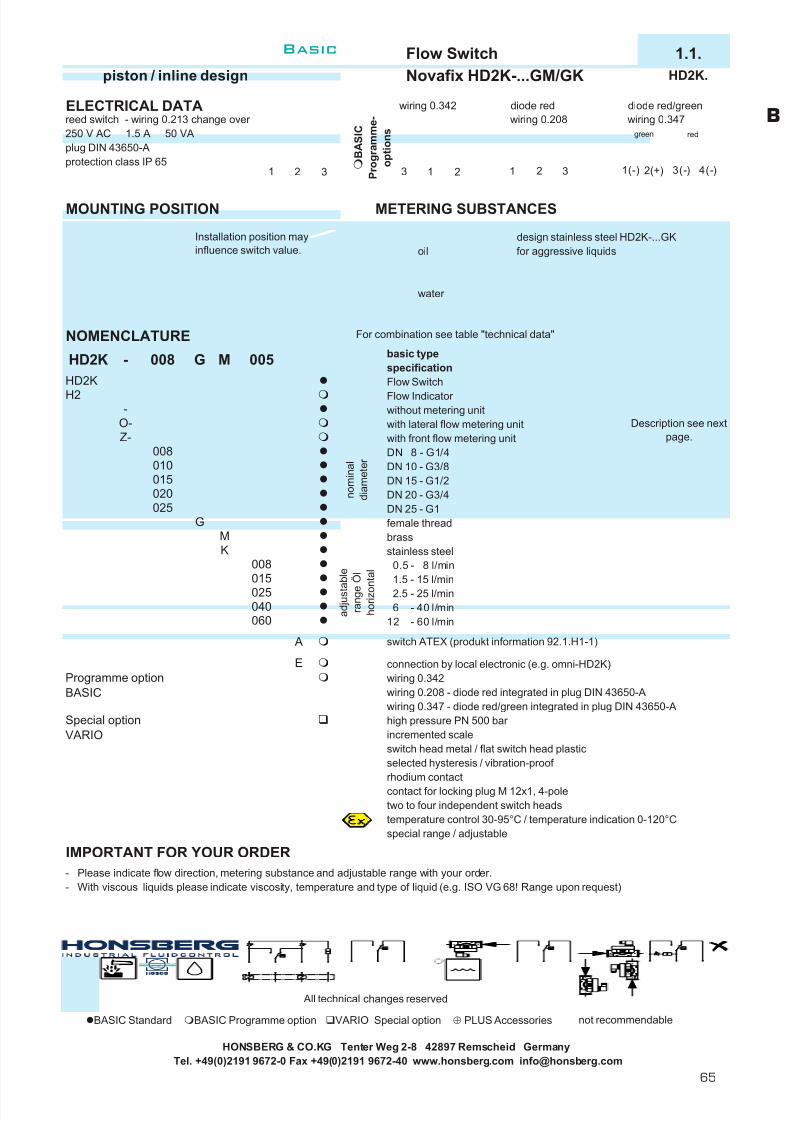
7/22/2019 General Honsberg
http://slidepdf.com/reader/full/general-honsberg 67/347
Flow Switch 1.1.piston / inline design Novafix HD2K-...GM/GK HD2K.
ELECTRICAL DATA wiring 0.342 diode red diode red/greenreed switch - wiring 0.213 change over wiring 0.208 wiring 0.347250 V AC 1.5 A 50 VAplug DIN 43650-Aprotection class IP 65
MOUNTING POSITION METERING SUBSTANCES
design stainless steel HD2K-...GKoil for aggressive liquids
water
NOMENCLATURE For combination see table "technical data"
basic typespecificationFlow SwitchFlow Indicator without metering unitwith lateral flow metering unitwith front flow metering unitDN 8 - G1/4DN 10 - G3/8DN 15 - G1/2DN 20 - G3/4DN 25 - G1female threadbrassstainless steel
0.5 - 8 l/min1.5 - 15 l/min2.5 - 25 l/min6 - 40 l/min
12 - 60 l/min
connection by local electronic (e.g. omni-HD2K)wiring 0.342wiring 0.208 - diode red integrated in plug DIN 43650-Awiring 0.347 - diode red/green integrated in plug DIN 43650-Ahigh pressure PN 500 bar incremented scaleswitch head metal / flat switch head plasticselected hysteresis / vibration-proof rhodium contactcontact for locking plug M 12x1, 4-poletwo to four independent switch headstemperature control 30-95°C / temperature indication 0-120°Cspecial range / adjustable
IMPORTANT FOR YOUR ORDER- Please indicate flow direction, metering substance and adjustable range with your order.- With viscous liquids please indicate viscosity, temperature and type of liquid (e.g. ISO VG 68! Range upon request)
All technical changes reserved
BASIC Standard BASIC Programme option VARIO Special option ⊕ PLUS Accessories not recommendable
HONSBERG & CO.KG Tenter Weg 2-8 42897 Remscheid GermanyTel. +49(0)2191 9672-0 Fax +49(0)2191 9672-40 www.honsberg.com [email protected]
Installation position mayinfluence switch value.
Description see nextpage.
switch ATEX (produkt information 92.1.H1-1) A
E
n o m i n a l
d i a m e t e r
HD2K
010
020
a d j u s t a
b l e
r a n g e
Ö l
h o r i z o n t a l
025
015
K
GM
005
VARIO
B A S I C
P r o g r a m m e -
o p t i o n s
MG-
008
HD2K
008
BASIC
060040
Programme option
025015
Special option
008
H2-
O-Z-
3 1 2 1 321 2 3 1(-) 2(+) 3(-) 4(-)
green red
Basic
B
65

7/22/2019 General Honsberg
http://slidepdf.com/reader/full/general-honsberg 68/347
Flow Switch 1.1.piston / inline design Novafix HD2K-...GM/GK HD2K.
The metering range is indicated for horizontally increasing flowprotection class IP 60additional weight 0.1kg
The metering range is indicated for horizontally increasing flowmedia temperatureprotection class IP 4 max. 70°Cadditional weight 0.1kg
EXAMPLES FOR FURTHER OPTIONS
media temperatuer 150°C Flex-K-HD2K omni-HD2Kcombinably with all switch- or frequency output 2xNPN and PNP switch point
Honsberg-electronics sensors 0..10V or 4..20mA 4(0)..20mA ouputor electronics heads PNP, NPN graphical LCD display
with flashing LED, program ring
All technical changes reserved
lBASIC Standard BASIC Programme option VARIO Special option ⊕ PLUS Accessories not recommendable
HONSBERG & CO.KG Tenter Weg 2-8 42897 Remscheid GermanyTel. +49(0)2191 9672-0 Fax +49(0)2191 9672-40 www.honsberg.com [email protected]
switch head metal or flat switchhead plastic, switch head ATEX
6 - 40 7.5 - 5012 - 60 15 - 70
HD2KZ- Flow Switch with front flow metering unit
adjustable range metering range
HD2KO- Flow Switch with lateral flow metering unit
1.5 - 15 2 - 202.5 - 25 2.5 - 30
0.5 - 8 0.5 - 101.5 - 15 2 - 20
l/min l/min
12 - 60 15 - 70
2.5 - 25 2.5 - 306 - 40 7.5 - 50
adjustable range metering range
l/min l/min0.5 - 8 0.5 - 10
Basic
66

7/22/2019 General Honsberg
http://slidepdf.com/reader/full/general-honsberg 69/347
Flow Switch 1.1.piston / inline design Novafix HM1K-...GM/GK HM1K.
GENERAL CHARACTERISTICS Female thread G1/4 - G1 brass/stainless steel
HM1K-020GM036
TECHNICAL DATA
Adjustable range is indicated for horizontally decreasing flow.
tolerance ±5% of full scalemedia temperature max. 70°Caverage pressure loss 0.5 bar at Qmax.hysteresis depending on switch value
minimum 1 l/min.
MATERIALS
HM1K-...GM HM1K-...GKbody brass Ms58 stainless steel 1.4571
nickel platedpiston brass Ms58 stainless steel 1.4404spring stainless steel 1.4310 stainless steel 1.4310magnet bariumferrite bariumferrite
PTFE platedseals NBR vitonswitch head polycarbonate polycarbonate
Tel. +49(0)2191 9672-0 Fax +49(0)2191 9672-40 www.honsberg.com [email protected]
Mechanical Flow Switch for liquids or gaseous media withspring supported piston and magnetic actuation of a microswitch. Robust design, produced in materials brass or stainless steel.
AFmm
Xmm
weightkg
0.5 - 4 1.315
200200
Qmax. recom.l/min H 2O
adjustable rangel/min H 2O
0.5 - 420200
6040
Type PNbar
200
200
HM1K-020GM...HM1K-015GM...
200HM1K-020GK...
18
1.31.21.2
10200
200
80
1515
10 40
40401 - 8
1 - 8 2 - 16
4 - 36
3 - 26
6 - 55
s t a i n l e s s
s t e e l
2 - 161 - 8HM1K-015GK...
0.5 - 4
60 4 - 366 - 55
200HM1K-025GK...
HONSBERG & CO.KG Tenter Weg 2-8 42897 Remscheid Germany
1.1
411.3
15151840
411.3
41
403 - 26 4 - 36
3 - 261 - 8
G 3/4G 1
1.1
1.218
4141
18
151.2
4 - 36
HM1K-025GM...
G 3/8G 1/2
G 1/4 HM1K-008GK004HM1K-010GK...
3 - 264020020 0.5 - 4
80
good repeatabiltydirt-resistancehigh switch capabilityhermetic separation of mechanicaland electrical componentexact setting of switch via scale + gear
G 3/4G 1
b r a s s
G
G 1/4G 3/8
HM1K-008GM004HM1K-010GM...
G 1/2
micro switch
Basic
B
67

7/22/2019 General Honsberg
http://slidepdf.com/reader/full/general-honsberg 70/347
Flow Switch 1.1.piston / inline design Novafix HM1K-...GM/GK HM1K.
ELECTRICAL DATA wiring 0.342 diode red diode red/greenmicro switch - wiring 0.371 change over wiring 0.208 wiring 0.347250 V AC 5 Aplug DIN 43650-Aprotection class IP 65
MOUNTING POSITION METERING SUBSTANCES
water gas/air
design stainless steel HM1K-...GKoil for aggressive liquids
NOMENCLATURE For combination see table "technical data"
basic typespecificationFlow SwitchFlow Switch with lateral flow metering unitFlow Switch with front flow metering unitDN 8 - G1/4DN 10 - G3/8DN 15 - G1/2DN 20 - G3/4DN 25 - G1female threadbrassstainless steel0.5 - 4 l/min1 - 8 l/min2 - 16 l/min3 - 26 l/min4 - 36 l/min6 - 55 l/minwiring 0.342wiring 0.208 - diode red integrated in plug DIN 43650-Awiring 0.347 - diode red/green integrated in plug DIN 43650-Aincremented scaleswitch head metalcontact for locking plug M 12x1, 4-polesetting / adjustable ranges for oil or gasspecial setting
IMPORTANT FOR YOUR ORDER- Please indicate flow direction, metering substance and adjustable range with your order.- With viscous liquids please indicate viscosity, temperature and metering substance (adjustable range on request)- With gaseous media indicate pressure (relative or absolute), temperature and metering substance (adjustable range on request)
All technical changes reserved
BASIC Standard BASIC Programme option VARIO Special option ⊕ PLUS Accessories not recommendable
HONSBERG & CO.KG Tenter Weg 2-8 42897 Remscheid GermanyTel. +49(0)2191 9672-0 Fax +49(0)2191 9672-40 www.honsberg.com [email protected]
026
Description see nextpage.
004008016
BASICProgramme option
Special option
K
VARIO
055036
020
B A S I C
P r o g r a m m e -
o p t i o n s
HM1K- MG
008
008HM1K-HM1KO-HM1KZ-
010
G
015
025
M
005
Installation position mayinfluence switch value.
n o m i n a l
d i a m e t e r
a d j u s t a b l e r a n g e
H 2 O
h o r i z o n t a l
3 1 2 1 321 2 3 1(-) 2(+) 3(-) 4(-)
green red
Basic
68

7/22/2019 General Honsberg
http://slidepdf.com/reader/full/general-honsberg 71/347
Flow Switch 1.1.piston / inline design Novafix HM1K-...GM/GK HM1K.
The metering range is indicated for horizontally increasing flowprotection class IP 60additional weight 0.1kg
The metering range is indicated for horizontally increasing flowmedia temperature max. 70°Cprotection class IP 40additional weight 0.1kg
EXAMPLES FOR FURTHER OPTIONS
media temperatuer 150°C Flex-K-HD1K omni-HD1Kcombinably with all switch- or frequency output 2xNPN and PNP switch point
Honsberg-electronics sensors 0..10V or 4..20mA 4(0)..20mA ouputor electronics heads PNP, NPN graphical LCD display
with flashing LED, program ring
All technical changes reserved
lBASIC Standard BASIC Programme option VARIO Special option ⊕ PLUS Accessories not recommendable
Tel. +49(0)2191 9672-0 Fax +49(0)2191 9672-40 www.honsberg.com [email protected]
5 - 65
3 - 26 3 - 34
switch head metal
6 - 55
HONSBERG & CO.KG Tenter Weg 2-8 42897 Remscheid Germany
4 - 36 4 - 45
0,5 - 61 - 8 1 - 122 - 16 2 - 22
adjustable range metering range
4 - 36 5 - 456 - 55 5 - 65
2 - 16 2 - 233 - 26 4 - 34
l/min H 2O0.5 - 4 0,5 - 61 - 8 1 - 12
l/min H 2O
HM1KO- Flow Switch with lateral flow metering unit
l/min H 2O l/min H 2O0.5 - 4
HM1KZ- Flow Switch with front flow metering unit
adjustable range metering range
Basic
B
69

7/22/2019 General Honsberg
http://slidepdf.com/reader/full/general-honsberg 72/347
Flow Switch 1.1.piston / inline design Novafix HR1MV-...GM/GK HR1MV.
GENERAL CHARACTERISTICS Female thread G1 1/4 to G2 brass/stainless steel
Adjustable range is indicated for horizontally decreasing flow. Calibration with oil ISO VG64 - 80mm²/s.
viscosity stability ±3%tolerance ±5% of full scalemedia temperature max. 120°Caverage pressure loss 0.5 bar at Qmax.hysteresis depending on switch value
value minimum 2 l/min.
MATERIALS
HR1MV-...GM HR1MV-...GKbody brass Ms58 stainless steel 1.4571
nickel platedmetering unit brass Ms58 stainless steel 1.4305spring 1.4310 stainless steel 1.4310magnet hardferrite hardferriteseal NBR (DN32-40 only) viton (DN32-40 only)
HONSBERG & CO.KG Tenter Weg 2-8 42897 Remscheid GermanyTel. +49(0)2191 9672-0 Fax +49(0)2191 9672-40 www.honsberg.com [email protected]
Within the mechanical viscosity compensation the flowvelocity in the piston area is increased sharply with theeffect that the viscosity impact declines and the meteringresults stabilise even with changing viscosity ratings.
PNbar
200200200
Qmax. rec.l/min H 2O
100150230100150230
200200200
10 - 4020 - 60
20 - 6016530 - 100
150165
29
2629
30 - 100G 2 150 2650 - 150
165
Lmm
165 2929
weightkg
6.05.7
AFmm
7070
Xmm
adjustable rangel/min oil 1-200mm²/s
10 - 4020 - 6030 - 100
20 - 6030 - 10050 - 150 5.2-
5.7- 5.2
6.07070
Mechanical Flow Switch for liquids or gaseous media, withspring-supported piston and magnetic triggering of a reedswitch. Rugged construction in brass or stainless steelwith additional viscosity compensation.
viscosity compensation 1-200mm²/srobust metal switch headgood repeatabiltydirt-resistancehigh switch capabilityhermetic separation of mechanicaland electrical component
b r a s s
s t a i n l e s s
s t e e l
G
G 1 1/4G 1 1/2G 2G 1 1/4G 1 1/2
HR1MV-032GK...HR1MV-040GK...HR1MV-050GK...
Type
HR1MV-032GM...HR1MV-040GM...HR1MV-050GM...
1 50 100 150 200 mm²/s
Q
HR1MV-032GM060
TECHNICAL DATA
Basic
70

7/22/2019 General Honsberg
http://slidepdf.com/reader/full/general-honsberg 73/347
Flow Switch 1.1.piston / inline design Novafix HR1MV-...GM/GK HR1MV.
ELECTRICAL DATAreed switch - wiring 0.213 change over 250 V AC 1.5 A 50 VAcable 2.5 mprotection class IP 65
MOUNTING POSITION METERING SUBSTANCES
water gas/air
oil
NOMENCLATURE For combination see table "technical data"
basic typespecificationFlow SwitchFlow Indicator without metering unitFlow Switch with lateral flow metering unitFlow Switch with front flow metering unitDN 32 - G1 1/4DN 40 - G1 1/2DN 50 - G2DN 65 - G2 1/2DN 80 - G3female threadbrassstainless steel10 - 40 l/min20 - 60 l/min30 - 100 l/min50 - 150 l/min
connection by local electronic (e.g. omni-HR1MV)signal lamp / diodeplug DIN 43650-A
setting / special rangesselected hysteresis / vibration-proof rhodium contacttemperature control 30 - 100 °Cswitch head contact for locking plug M 12x1, 4-pole
TuchelHarting
two to four independent switch heads
IMPORTANT FOR YOUR ORDER- Please indicate flow direction, metering substance and adjustable range with your order.- With viscous liquids (>200mm²/s) please indicate viscosity, temperature and type of liquid (e.g. ISO VG 68! Range upon request)- With gaseous media indicate pressure (relative or absolute), temperature and metering substance (adjustable range on request)
All technical changes reserved
BASIC Standard BASIC Programme option VARIO Special option ⊕ PLUS Accessories not recommendable
HONSBERG & CO.KG Tenter Weg 2-8 42897 Remscheid GermanyTel. +49(0)2191 9672-0 Fax +49(0)2191 9672-40 www.honsberg.com [email protected]
-O-Z-
040060
H1V
040
A switch ATEX (produkt information 92.1.H1-2)
100
Description see nextpage.
080065050040
M
G M
Installation position mayinfluence switch value.
G
032
150
E
a d j u s a b l e
r a n g e
Programme optionBASIC
Special optionVARIO
n o m i n a l
d i a m e t e r
HR1MV 032HR1MV
K
blue black green/yellow
brown
Basic
B
71
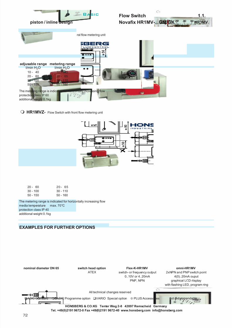
7/22/2019 General Honsberg
http://slidepdf.com/reader/full/general-honsberg 74/347
Flow Switch 1.1.piston / inline design Novafix HR1MV-...GM/GK HR1MV.
The metering range is indicated for horizontally increasing flowprotection class IP 60additional weight 0.1kg
The metering range is indicated for horizontally increasing flowmedia temperature max. 70°Cprotection class IP 40additional weight 0.1kg
EXAMPLES FOR FURTHER OPTIONS
nominal diameter DN 65 switch head option Flex-K-HR1MV omni-HR1MV ATEX switch- or frequency output 2xNPN and PNP switch point
0..10V or 4..20mA 4(0)..20mA ouputPNP, NPN graphical LCD display
with flashing LED, program ring
All technical changes reserved
lBASIC Standard BASIC Programme option VARIO Special option ⊕ PLUS Accessories not recommendable
Tel. +49(0)2191 9672-0 Fax +49(0)2191 9672-40 www.honsberg.com [email protected]
50 - 150 50 - 160
50 - 150 50 - 160
20 - 60
l/min H 2O l/min H 2Oadjusable range
20 - 60 20 - 6530 - 100 30 - 110
l/min H 2O
HR1MVZ- Flow Switch with front flow metering unit
metering range
10 - 40 10 - 45
HR1MVO- Flow Switch with lateral flow metering unit
adjusable range metering rangel/min H 2O
10 - 40 10 - 45
30 - 100 30 - 11020 - 65
HONSBERG & CO.KG Tenter Weg 2-8 42897 Remscheid Germany
Basic
72

7/22/2019 General Honsberg
http://slidepdf.com/reader/full/general-honsberg 75/347
Flow Switch 1.1.piston / inline design Fluvamat MF-003GM MF.003
GENERAL CHARACTERISTICS Female thread M5 brass
MF-003GM
TECHNICAL DATA
Switch value is indicated for horizontally descreasing flow.
tolerance ±15% of full scalemedia temperature max. 80°C
MATERIALS
body brass Ms58piston brass Ms58spring stainless steel 1.4310magnet bariumferriteseal NBR
MOUNTING POSITION ELECTRICAL DATAreed switch - wiring 0.212 n.o.125 V AC 0.5 A 10 VAconnection: two wires 170mmprotection class IP 65
METERING SUBSTANCES NOMENCLATUREbasic typespecification
gas/air female thread M5brass
IMPORTANT FOR YOUR ORDER- Please indicate flow direction, metering substance and switch value
with your order.- With gaseous media indicate pressure (relative or absolute),
temperature and metering substance (switch value on request)
All technical changes reserved
BASIC Standard BASIC Programme option VARIO Special option ⊕ PLUS Accessories not recommendable
HONSBERG & CO.KG Tenter Weg 2-8 42897 Remscheid GermanyTel. +49(0)2191 9672-0 Fax +49(0)2191 9672-40 www.honsberg.com [email protected]
M
Installation position mayinfluence switch value.
GG
M
003
Mechanical Flow Switch for gaseous media, with magnetictriggering of a reed switch. Rugged design in brass.
compact dimensionscontrol of small flow rates
Type
MF-003GM
Qmax. recomendedl/min
MF-
PNbar
6 100air 1bar 20°C
0.06
weightkg
brass M5
M
air 1bar 20°C
switch value l/minselectable range for fixed switch
1 - 100
1 2
Basic
B
73

7/22/2019 General Honsberg
http://slidepdf.com/reader/full/general-honsberg 76/347
Flow Switch 1.1.piston / inline design Fluvamat MF-007GM MF.007
GENERAL CHARACTERISTICS Female thread M10x1 brass
TECHNICAL DATA
The switch value is valid for flow to up and decreasing flow.
tolerance ±15% of full scalemedia temperature max. 80°Caverage pressure loss 0.15 bar at Qmax.hysteresis depending on the switch
value minimum 0.4 l/min.
MATERIALS
body brass Ms58piston brass Ms58spring bariumferriteseal NBR
MOUNTING POSITION ELECTRICAL DATAreed switch - wiring 0.212 n.o.120 V AC 0.5 A 10 VAconnection 2 leads 300mmprotection class IP 65
METERING SUBSTANCES NOMENCLATUREbasic typespecification
water female thread M10x1brass
IMPORTANT FOR YOUR ORDER- Please indicate switch value with your order.
All technical changes reserved
BASIC Standard BASIC Programme option VARIO Special option ⊕ PLUS Accessories not recommendable
Mechanical Flow Switch for water, with magnetictriggering of a reed switch. Rugged design in brass.
control of small flow ratesadjustable switch value
M
M
M
M10x1
007MF-
brass
PNbar
Qmax. recomendedl/min H 2O
6 2MF-007GM
Type weightkg
0.180.05 - 1.0
switch value l/min H 2Oselectable range for fixed switch
G
MF-007GM
G
HONSBERG & CO.KG Tenter Weg 2-8 42897 Remscheid GermanyTel. +49(0)2191 9672-0 Fax +49(0)2191 9672-40 www.honsberg.com [email protected]
1 2
Basic
74

7/22/2019 General Honsberg
http://slidepdf.com/reader/full/general-honsberg 77/347
Flow Switch 1.1.piston / inline design Fluvamat MR-...GM/GK MR.
GENERAL CHARACTERISTICS Female thread G1/4 to G1 brass/stainless steel
MR-020GM020
TECHNICAL DATA
Adjustable range is indicated for horizontally decreasing flow.
tolerance ±5% of full scalemedia temperature max. 120°Caverage pressure loss 0.5 bar at Qmax.hysteresis depending on switch value
minimum 0.5 l/min.
MATERIALS
MR-...GM MR-...GKbody brass Ms58 stainless steel 1.4305
nickel platedpiston brass Ms58 stainless steel 1.4571
stainless steel 1.4305; stainless steel 1.4305;1.4301 1.4301
spring stainless steel 1.4310 stainless steel 1.4310magnet bariumferrite bariumferrite
PTFE platedseal NBR vitonswitch head PA PA
HONSBERG & CO.KG Tenter Weg 2-8 42897 Remscheid GermanyTel. +49(0)2191 9672-0 Fax +49(0)2191 9672-40 www.honsberg.com [email protected]
G 1/4
0.4 - 45 - 205 - 20
1 - 10
1 - 10
56
Mechanical Flow Switch for liquids or gaseous media withspring supported piston and magnetic actuation of a reedswitch. Robust design, produced in materials brass or stainless steel.
compact dimensiongood repeatabiltydirt-resistancehigh switch capabilityhermetic separation of mechanicaland electrical component
adjustable rangel/min H 2O
0.4 - 40.4 - 4 1 - 10
PNbar
TypeG
G 3/8
3656 36
10 - 4020 - 60
109
135109
1095 - 20
40
200
MR-008GM...MR-010GM...
MR-020GM... 200200
0.80
200 41
121218
109
12 0.8536
1.505656
0.80
200
200MR-015GK...
G 1
0.800.80
109 56109 1256
12
1.501812
5656
4036 0.85
weightkg
0.850.85
Lmm
109109
AFmm
Xmm
1212
Hmm
5656
MR-015GM...
200200200
Qmax. rec.l/min H 2O
1520
G 3/8G 1/2
MR-020GK...
MR-010GK...
G 3/4
36363636
s t a i n l e s s
s t e e l
b r a s s
G 1/2
G 1/4
G 3/4G 1
MR-008GK...
200
13510 - 4020 - 60
5 - 20
5 - 20 10 - 40
0.4 - 4 1 - 10
MR-025GK...
0.4 - 4 1 - 101 - 10 5 - 20
5 - 20 10 - 400.4 - 4
608015
1 - 10 5 - 20
1 - 10MR-025GM...
20
80
4060
Basic
B
75

7/22/2019 General Honsberg
http://slidepdf.com/reader/full/general-honsberg 78/347
Flow Switch 1.1.piston / inline design Fluvamat MR-...GM/GK MR.
ELECTRICAL DATAreed switch - wiring 0.213 change over 250 V AC 1.5 A 50 VAcable 2.5 mprotection class IP 65
MOUNTING POSITION METERING SUBSTANCES
water gas/air
design stainless steel MR-...GKoil for aggressive liquids
NOMENCLATURE For combination see table "technical data"
basic typespecificationFlow SwitchFlow Switch with lateral flow metering unit ( DN 8-20 - PN90 )DN 8 - G1/4DN 10 - G3/8DN 15 - G1/2DN 20 - G3/4DN 25 - G1female threadbrassstainless steel
0.4 - 4 l/min1 - 10 l/min5 - 20 l/min
10 - 40 l/min20 - 60 l/minsetting / adjustable ranges for oil or gasspecial rangesselected hysteresis / vibration-proof rhodium contacthigh pressure PN 400 bar plug DIN 43650-Aconnection for locking plug M12x1 , 4-pole
IMPORTANT FOR YOUR ORDER- Please indicate flow direction, metering substance and adjustable range with your order.- With viscous liquids please indicate viscosity, temperature and metering substance (adjustable range on request)- With gaseous media indicate pressure (relative or absolute), temperature and metering substance (adjustable range on request)
OPTION
Installation position mayinfluence switch value.
G
KM
015
MRO-
MR-MR-
008
10 - 40 5 - 40
Special option
20 - 60
1 - 105 - 251 - 12
5 - 20
0.4 - 4 0.5 - 5
adjustable range metering range
010008
G
n o m i n a l
d i a m e t e r
025
004
020
a d j u s t a b l e
r a n g e H
2 O
h o r i z o n t a l
M 004
VARIO
060040
010
20 - 60
l/min H 2O l/min H 2O
020
brow n bl ue black
MRO- Flow Switch with lateral flow metering
The metering range is indicated for horizontally increasing flowDN 8-20 PN 90 bar protection class IP 60DN 25 PN 200 bar additional weight 0.1kg
All technical changes reserved
BASIC Standard BASIC Programme option VARIO Special option ⊕ PLUS Accessories not recommendable
HONSBERG & CO.KG Tenter Weg 2-8 42897 Remscheid GermanyTel. +49(0)2191 9672-0 Fax +49(0)2191 9672-40 www.honsberg.com [email protected]
Basic
76

7/22/2019 General Honsberg
http://slidepdf.com/reader/full/general-honsberg 79/347
Flow Switch 1.1.piston / inline design Novafix MR1K-...GM/GK MR1K.
GENERAL CHARACTERISTICS Female thread G1/4 to G1 brass/stainless steel
Adjustable range is indicated for horizontally decreasing flow.
tolerance ±5% of full scalemedia temperature max. 120°Caverage pressure loss 0.5 bar at Qmax.hysteresis depending on switch value
minimum 0.5 l/min.
MATERIALS
MR1K-...GM MR1K-...GKbody brass Ms58 stainless steel 1.4571
nickel platedpiston brass Ms58 stainless steel 1.4404spring stainless steel 1.4310 stainless steel 1.4310magnet bariumferrite bariumferrite
PTFE platedseal NBR vitonswitch head polycarbonate polycarbonate
HONSBERG & CO.KG Tenter Weg 2-8 42897 Remscheid GermanyTel. +49(0)2191 9672-0 Fax +49(0)2191 9672-40 www.honsberg.com [email protected]
G 1/4G 3/8 1.3
1.2151 - 10
200
MR1K-015GK...
MR1K-008GK004
1.1
G 1/2G 3/4G 1 6 - 60
4 - 40184 - 40
Mechanical Flow Switch for liquids or gaseous media withspring supported piston and magnetic actuation of a reedswitch. Robust design, produced in materials brass or stainless steel.
compact dimensiongood repeatabiltydirt-resistancehigh switch capabilityhermetic separation of mechanicaland electrical component
b r a s s
s t a i n l e s s
s t e e l
G
G 1/4G 3/8G 1/2G 3/4G 1
40
AFmm
40
adjustable rangel/min H 2O
1 - 100.4 - 4 1515
weightkg
1.31.3
Xmm
15
181.21.2MR1K-020GM... 40
40200 403 - 304 - 40
10
1 - 10 2 - 20
0.4 - 4
60
20
3 - 30
MR1K-008GM004
MR1K-015GM...200
PNbar
200200
Type
MR1K-010GM...
Qmax. recom.l/min H 2O
80MR1K-025GM...
41
41
0.4 - 4
3 - 304141
2 - 20 3 - 30
200
1.21518
1.11.315
1 - 10
404110
4060
20
80
MR1K-010GK...
MR1K-025GK...
200200200200
MR1K-020GK...
180.4 - 4
6 - 604 - 40
MR1K-010GM004
TECHNICAL DATA
Basic
B
77

7/22/2019 General Honsberg
http://slidepdf.com/reader/full/general-honsberg 80/347
Flow Switch 1.1.piston / inline design Novafix MR1K-...GM/GK MR1K.
ELECTRICAL DATA wiring 0.342 diode red diode red/greenreed switch - wiring 0.213 change over wiring 0.208 wiring 0.347250 V AC 1.5 A 50 VAplug DIN 43650-Aprotection class IP 65
MOUNTING POSITION METERING SUBSTANCES
water gas/air
design stainless steel MR1K-...GKoil for aggressive liquids
NOMENCLATURE For combination see table "technical data"
basic typespecificationFlow SwitchFlow Switch with magnetic indicationFlow Switch with lateral flow metering unitDN 8 - G1/4DN 10 - G3/8DN 15 - G1/2DN 20 - G3/4DN 25 - G1female threadbrassstainless steel0.4 - 4 l/min1 - 10 l/min2 - 20 l/min3 - 30 l/min4 - 40 l/min6 - 60 l/minconnection by local electronic (e.g. omni-MR1K)wiring 0.342wiring 0.208 - diode red integrated in plug DIN 43650-Awiring 0.347 - diode red/green integrated in plug DIN 43650-Asetting / adjustable ranges for oil or gasspecial ranges / selected hysteresis / vibration-proof high pressure PN 500 bar two to four independent switch heads
IMPORTANT FOR YOUR ORDER- Please indicate flow direction, metering substance and adjustable range with your order.- With viscous liquids please indicate viscosity, temperature and metering substance (adjustable range on request)- With gaseous media indicate pressure (relative or absolute), temperature and metering substance (adjustable range on request)
OPTION
Metering range is indicated for horizontally increasing flow. Protection class IP60 8o9. Additional weight 0.1kg
All technical changes reserved
BASIC Standard BASIC Programme option VARIO Special option ⊕ PLUS Accessories not recommendable
HONSBERG & CO.KG Tenter Weg 2-8 42897 Remscheid GermanyTel. +49(0)2191 9672-0 Fax +49(0)2191 9672-40 www.honsberg.com [email protected]
E060
030040
004
MR1KJ-
B A S I C
P r o g r a m m e -
o p t i o n s
Programme optionBASIC
Special optionVARIO
K
020010004
n o m i n a l
d i a m e t e r
008 M
a d j u s t a b l e r a n g e
H 2
O h o r i z o n t a l
015
025020
010
Installation position mayinfluence switch value.
GMR1K-MR1K-
MR1KO-
1 - 12
5 - 65
l/min H 2O
4 - 34
M
0.5 - 5
2 - 23
G
5 - 45
metering range
008
MR1KJflow switcht withmagnetic indication 10-100%
l/min H 2Oadjustable range
MR1KOFlow Switch with lateral flow metering
6 - 60
0.4 - 41 - 102 - 203 - 304 - 40
3 1 2 1 321 2 3 1(-) 2(+) 3(-) 4(-)
green red
Basic
78

7/22/2019 General Honsberg
http://slidepdf.com/reader/full/general-honsberg 81/347
Flow Switch 1.1.piston / inline design Fluvamat RVM-008GM/GK RVM.
GENERAL CHARACTERISTICS Female thread G1/4 brass/stainless steel
TECHNICAL DATA
Adjustable range is indicated for horizontally decreasing flow.
tolerance ±10% of full scalemedia temperature max. 100°Caverage pressure loss 0.02-0.2 bar at Qmax.hysteresis depending on switch value
minimum 1 ml/min.
MATERIALS
RVM-008GM RVM-008GKbody brass Ms58 stainless steel 1.4571
nickel platedpiston brass Ms58 stainless steel 1.4571spring stainless steel 1.4571 stainless steel 1.4571magnet hardferrite hardferrite
HONSBERG & CO.KG Tenter Weg 2-8 42897 Remscheid GermanyTel. +49(0)2191 9672-0 Fax +49(0)2191 9672-40 www.honsberg.com [email protected]
RVM-008GK013RVM-008GK060
300300
G1/4
Mechanical Flow Switch for liquids or gaseous media, withmagnetic triggering of an adjustable reed switch. Ruggeddesign in brass or stainless steel.
control of small flow ratesPN 300hermetic separation of mechanicaland electrical component
G
G1/4
Type
300
300300
RVM-008GM013RVM-008GM060
RVM-008GK300 3.6 0.15300
weightkg
0.14
adjustable rangeH2O
Bmm
17
17
40 - 130 ml/min
l/min17l/min
0.5 - 3.0RVM-008GM300
PNbar
Qmax. recom.H2O
0.1 - 0.6168 ml/min
18 0.15ml/min168 ml/min 40 - 13018
l/minl/min
0.5 - 3.00.1 - 0.6 l/min
l/min 18
b r a s s
s t a i n
-
l e s s
s t e e l
0.14
0.72
0.72 l/min
0.15
0.143.6 l/min
Basic
B
79

7/22/2019 General Honsberg
http://slidepdf.com/reader/full/general-honsberg 82/347
Flow Switch 1.1.piston / inline design Fluvamat RVM-008GM/GK RVM.
ELECTRICAL DATAReed switch - wiring 0.212 n.o. wiring 0.342200 V AC 1 A 20 VAPlug DIN 43650-CProtection class IP 65
MOUNTING POSITION METERING SUBSTANCES
design stainless steel RVM-...GKwater for aggressive liquids
gas/air
NOMENCLATURE For combination see table "technical data"
basic typespecificationnominal diameter DN 8 - G1/4female threadbrassstainless steeladjustable range 40 - 130 ml/min H 2Oadjustable range 0.1 - 0.6 l/min H 2Oadjustable range 0.5 - 3.0 l/min H 2Owiring 0.213, change over
BASICsetting / switch ranges for gas
VARIO
IMPORTANT FOR YOUR ORDER- Please indicate flow direction, metering substance and adjustable range with your order.- With gaseous media indicate pressure (relative or absolute), temperature and metering substance (adjustable range on request)
All technical changes reserved
BASIC Standard BASIC Programme option VARIO Special option ⊕ PLUS Accessories not recommendable
300Programme option
013060
G
K
Special option
M
MG
B A S I C
P r o g r a m m e
o p t i o n
Installation position mayinfluence switch value.
008008
RVM- 014
HONSBERG & CO.KG Tenter Weg 2-8 42897 Remscheid GermanyTel. +49(0)2191 9672-0 Fax +49(0)2191 9672-40 www.honsberg.com [email protected]
1 2 3 1 2
Basic
80

7/22/2019 General Honsberg
http://slidepdf.com/reader/full/general-honsberg 83/347
Flow Indicator 1.2.piston / inline design Visoflow NH1-...GM NH1.
GENERAL CHARACTERISTICS Female thread G1/2 brass
TECHNICAL DATA NH1-015GM015
Indicating range is calibrated for vertical upward increasing flow.
tolerance ±10% of full scalemedia temperature max. 65°C
MATERIALS
connector brass Ms58 nickel platedtube Acryl XTpiston POMspring 1.4310seal Viton
MOUNTING POSITION METERING SUBSTANCES
water
NOMENCLATUREbasic typespecificationflow indicator flow indicator with switch unit plasticnominal diameter DN 15
female threadmale threadconnection brassindicating range 3 - 15 l/min
IMPORTANT FOR YOUR ORDER
- Please indicate flow direction, metering substance and indication range with your order.
OPTIONSNH1K- flow indicator with switch unit plastic
reed switch - wiring 0.212 n.o.250 V AC 0.5 A 10 VA Swich range is indicatedcontact for locking plug M 12x1, 4-pole for horizontally decreasing flow.protection class IP 65 Additional weight 0.02kg
All technical changes reserved
BASIC Standard BASIC Programme option VARIO Special option ⊕ PLUS Accessories not recommendable
NH1- G015
NH1K-
Type
HONSBERG & CO.KG Tenter Weg 2-8 42897 Remscheid GermanyTel. +49(0)2191 9672-0 Fax +49(0)2191 9672-40 www.honsberg.com [email protected]
NH1-
weightkg
indicating rangel/min H 2O
3 - 15 0.3
Installation position mayinfluence indication range.Indicate installation position inyour order
20
G
10
The flow indicator Visoflow NH provides a reliableIndication of liquid, transparent substances. A springcontrolled indicator is positioned by the liquid in ametering tube and allows the quantitative indication of theflow rate involved by reference to the flow rate scale of themetering tube. This plastic tube is fitted with a pigeon tailwhich offers the option of an alarm unit which is adjustablewithin the scale range of the instrument.
turnable scale / visible of piston 360°good repeatabilty
G
G1/2
PNbar
(20°C)
Qmax. recom.l/min H 2O
M
AM
015
015
NH1-015GM015brass
015
1brown
2white
3blue
4black
free
Basic
B
81

7/22/2019 General Honsberg
http://slidepdf.com/reader/full/general-honsberg 84/347
Flow Indicator 1.2.piston / inline design Novaflux NJ-...GM/GK NJ.
GENERAL CHARACTERISTICS Female G1/4 to G1 brass/stainless steel
TECHNICAL DATA NJ-015GM040
Indicating range is calibrated for vertical upward increasing flow.
tolerance ±8% of full scale min. 1l/minmedia temperature max. 100°Caverage pressure loss 0.5bar at Qmax.
MATERIALS
NJ-...GM NJ-...GKbody brass Ms58 stainless steel 1.4571
nickel platedpiston brass Ms58 stainless steel 1.4571 ;
1.4310spring stainless steel 1.4310 stainless steel 1.4310magnet bariumferrite bariumferrite
PTFE platedseals NBR vitonscale acrylic (GS) acrylic (GS)
HONSBERG & CO.KG Tenter Weg 2-8 42897 Remscheid GermanyTel. +49(0)2191 9672-0 Fax +49(0)2191 9672-40 www.honsberg.com [email protected]
2 - 102 - 102 - 10
60
100
100
NJ-008GK010G 1/4
s t a i n l e s s
s t e e l
Mechanical Flow Indicator for liquids or gaseous media,with spring-supported piston. Piston is magnetically linkedto an indicator element. Rugged design in brass or stainless steel.
multiviscosity scalefor dark and/or contaminated liquidsgood repeatabiltydirt resistance
G
b r a s s
G 1/4G 3/8G 1/2
PNbar
100100
10 - 4010 - 40
20 - 80G 3/4G 1 100
10080
100
4 - 20 10 - 40
80
4 - 20
4 - 20
10 - 404 - 204 - 2060
20
2 - 10 4 - 20 10 - 40 20 - 80
weightkg
1.5
indication range multi scale1
indicating rangel/min H 2O
2 - 10
Qmax. recom.l/min H 2O
10
NJ-020GK...
1.4
1.4
1.31.31.21.5
4 - 20
2 - 10
NJ-010GK...
NJ-025GK...2 - 10100 10 - 40
G 1
Type
NJ-010GM...
NJ-025GM...
G 3/8G 1/2G 3/4
NJ-015GM...
2 - 10NJ-020GM...
NJ-015GK...
NJ-008GM0102 - 10
20
2 - 10100 40
10
1.31.31.2
4 - 20100 40
20-45 75-120 180-250 mm²/sl/min
4-20 2 -19 1 -17 0.5-15 l/min2-10 0.6- 8 0.2- 7 0.1- 4
l/min20-80 19 -73 17 -68 13 -63 l /min10-40 7 -38 6 -37 4 -36
Basic
82

7/22/2019 General Honsberg
http://slidepdf.com/reader/full/general-honsberg 85/347
Flow Indicator 1.2.piston / inline design Novaflux NJ-...GM/GK NJ.
ELECTRICAL DATA
No electrical components switch headsfor descriptions see following page
MOUNTING POSITION METERING SUBSTANCES
water gas/air
design stainless steel NJ-...GKoil for aggressive liquids
NOMENCLATURE For combination see table "technical data"
basic typespecificationFlow Indicator Flow Indicator with switch head metal, wiring 0.333 (NJE100)Flow Indicator with switch head metal, wiring 0.215 (NJE200)Flow Indicator with switch head plastic, wiring 0.338 (NJE400)Flow Indicator with switch head plastic, wiring 0.215Flow Indicator with switch head plastic, wiring 0.347 (NJE400sp)DN 8 - G1/4DN 10 - G3/8DN 15 - G1/2DN 20 - G3/4DN 25 - G1female threadmanifold block connector for 70.1.VB.brassstainless steel
2 - 10 l/min4 - 20 l/min
10 - 40 l/min20 - 80 l/minsignal lamp
BASICspecial rangespecial scalesmanifold block - data sheet 70.1.VB.
IMPORTANT FOR YOUR ORDER- Please indicate flow direction, metering substance and indicating range with your order.- With viscous liquids please indicate viscosity, temperature and metering substance (indicating range on request)- With gaseous media indicate pressure (relative or absolute), temperature and metering substance (indicating range on request)
ACCESSORIES
Manifoldsee datd sheet 70.1.VB.
All technical changes reserved
BASIC Standard BASIC Programme option VARIO Special option ⊕ PLUS Accessories not recommendable
HONSBERG & CO.KG Tenter Weg 2-8 42897 Remscheid GermanyTel. +49(0)2191 9672-0 Fax +49(0)2191 9672-40 www.honsberg.com [email protected]
i n d i c a t i n g
r a n g e
n o m i n a l
d i a m e t e r
G
020
008
015
025
Installation position mayinfluence indicatingrange. Scale arrange -ment for upward flow.
BASIC Standard
M
080
010
W
010
H2O upward flow
BASIC Programme option
008
NJK2-
NJ-
MNJ-
NJK3-
NJM1-
010
NJK1-NJM2-
020
PLUS
VARIO
Programme option
⊕
Special option
040
Accessories
G
K
Basic
B
83

7/22/2019 General Honsberg
http://slidepdf.com/reader/full/general-honsberg 86/347
Flow Indicator 1.2.piston / inline design Novaflux NJ-...GM/GK NJ.
OPTION
switch head metalreed switchwiring 0.333 (NJE100)
switching voltage 250 V AC 5 Asupply voltage 230 V AC(option 115 V AC)(option 24 V DC output circuit 10mA)cable gland Pg9 with 2.5 metre cableprotection class IP 65additional weight 0.45kg
reed switchwiring 0.215 (NJE200)250 V AC 0.5 A 10 VAcable gland Pg9 with 2.5 metre cable
protection class IP 65additional weight 0.45kg
switch head plasticreed switchwiring 0.338 (NJE400)250 V AC 0.5 A 10 VAplug DIN 43650-Aprotection class IP 65additional weight 0.15kg
switch head plasticreed switchwiring 0.215250 V AC 0.5 A 10 VAplug DIN 43650-Aprotection class IP 65additional weight 0.15kg
switch head plasticreed switchwiring 0.347 (NJE400sp)24 V DCplug Hirschmann G4protection class IP 65additional weight 0.15kg
All technical changes reserved
BASIC Standard BASIC Programme option VARIO Special option ⊕ PLUS Accessories not recommendable
NJM2-
NJK1-
Attention! Only switch head grounded notbody of Flow Indicator
Attention! Only switch head grounded notbody of Flow Indicator
NJK3-
NJK2-
NJM1-
HONSBERG & CO.KG Tenter Weg 2-8 42897 Remscheid GermanyTel. +49(0)2191 9672-0 Fax +49(0)2191 9672-40 www.honsberg.com [email protected]
brow n blue green/yellow
1(-) 2(+) 3(-) 4(-)
green red
1(+) 2 3(-)
1 2
yellow beige brown blue black green/yellowwhitegrey
Basic
84

7/22/2019 General Honsberg
http://slidepdf.com/reader/full/general-honsberg 87/347
Flow Indicator 1.2.piston / inline design Novaflux NJV-...GM NJV.
GENERAL CHARACTERISTICS Female thread G1/4 to G1 brass
NJV-015GM040
TECHNICAL DATA
Indicating range is calibrated for vertical upward increasing flow. Calibration with oil ISO VG64 - 80mm²/s.
tolerance ±8% of full scale min. 1l/minmedia temperature max. 100°Caverage pressure loss 0.5bar at Qmax.
MATERIALS
body brass Ms58 nickel platedmetering unit brass Ms58spring stainless steel 1.4310magnet neodymseal NBRscale acrylic (GS)
Mechanical Flow Indicator for liquids or gaseous media,with spring-supported piston. Piston is magnetically linkedto an indicator element. Rugged design in brass.
viscosity compensation 1-200mm²/sfor dark and/or contaminated liquidsgood repeatabiltydirt-resistance
indicating rangel/min oil 1-200mm²/s
weightkg
Qmax. recom.l/min oil
1-200mm²/s
G Type PNbar
4- 20 10- 40
1.4
2- 10 10- 601.31.2
10- 60100
60NJV-025GM...
Within the mechanical viscosity compensation the flowvelocity in the piston area is increased sharply with theeffect that the viscosity impact declines and the meteringresults stabilise even with changing viscosity ratings.
100NJV-008GM010 10 2- 10
b r a s s
G 1/2
G 1
G 1/4
G 3/4
NJV-010GM...
NJV-020GM...
G 3/8NJV-015GM...
2- 101.5
1.310- 402- 10 4- 204- 20100
4010- 404- 20
20
2- 1010080
100
HONSBERG & CO.KG Tenter Weg 2-8 42897 Remscheid GermanyTel. +49(0)2191 9672-0 Fax +49(0)2191 9672-40 www.honsberg.com [email protected]
1 50 100 150 200 mm²/s
Q
Basic
B
85

7/22/2019 General Honsberg
http://slidepdf.com/reader/full/general-honsberg 88/347
Flow Indicator 1.2.piston / inline design Novaflux NJV-...GM NJV.
ELECTRICAL DATA
No electrical components switch headsfor descriptions see following page
MOUNTING POSITION METERING SUBSTANCES
oil
gas/air
NOMENCLATURE For combination see table "technical data"
basic typespecificationFlow Indicator Flow Indicator with switch head metal, wiring 0.333 (NJE100)Flow Indicator with switch head metal, wiring 0.215 (NJE200)Flow Indicator with switch head plastic, wiring 0.338 (NJE400)Flow Indicator with switch head plastic, wiring 0.215Flow Indicator with switch head plastic, wiring 0.347 (NJE400sp)DN 8 - G1/4DN 10 - G3/8DN 15 - G1/2DN 20 - G3/4DN 25 - G1female threadmanifold block connector for 70.1.VB.brassstainless steel
2- 10 l/min4- 20 l/min
10- 40 l/min10- 60 l/minsignal lamp
BASICspecial rangesspecial scalesmanifold block - data sheet 70.1.VB.
IMPORTANT FOR YOUR ORDER- Please indicate flow direction, metering substance and indicating range with your order.- With viscous liquids (>200mm²/s) please indicate viscosity, temperature and type of liquid (e.g. ISO VG 68! Range upon request)- With gaseous media indicate pressure (relative or absolute), temperature and metering substance (indicating range on request)
ACCESSORIES
Manifoldsee datd sheet 70.1.VB.
All technical changes reserved
BASIC Standard BASIC Programme option VARIO Special option ⊕ PLUS Accessories not recommendable
HONSBERG & CO.KG Tenter Weg 2-8 42897 Remscheid GermanyTel. +49(0)2191 9672-0 Fax +49(0)2191 9672-40 www.honsberg.com [email protected]
oil 1-200mm²/s upward flow
n o m i n a l
d i a m e t e r
008010
PLUS
015020
MNJV-
NJV-
NJVM1-
008 G 010
025G
MK
Special option
020010
Accessories ⊕
i n d i c a t i n g
r a n g e
Programme option060
VARIO
040
NJVK1-NJVM2-
NJVK2-NJVK3-
W
BASIC Standard BASIC Programme option
Installation position mayinfluence indicatingrange. Scale arrange -ment for upward flow.
Basic
86

7/22/2019 General Honsberg
http://slidepdf.com/reader/full/general-honsberg 89/347
Flow Indicator 1.2.piston / inline design Novaflux NJV-...GM NJV.
OPTION
switch head metalreed switchwiring 0.333 (NJE100)
switching voltage 250 V AC 5 Asupply voltage 230 V AC(option 115 V AC)(option 24 V DC output circuit 10mA)cable gland Pg9 with 2.5 metre cableprotection class IP 65additional weight 0.45kg
switch head metalreed switchwiring 0.215 (NJE200)250 V AC 0.5 A 10 VAcable gland Pg9 with 2.5 metre cable
protection class IP 65additional weight 0.45kg
switch head plasticreed switchwiring 0.338 (NJE400)250 V AC 0.5 A 10 VAplug DIN 43650-Aprotection class IP 65additional weight 0.15kg
switch head plasticreed switchwiring 0.215250 V AC 0.5 A 10 VAplug DIN 43650-Aprotection class IP 65additional weight 0.15kg
switch head plasticreed switchwiring 0.347 (NJE400sp)24 V DCplug Hirschmann G4protection class IP 65additional weight 0.15kg
All technical changes reserved
BASIC Standard BASIC Programme option VARIO Special option ⊕ PLUS Accessories not recommendable
HONSBERG & CO.KG Tenter Weg 2-8 42897 Remscheid GermanyTel. +49(0)2191 9672-0 Fax +49(0)2191 9672-40 www.honsberg.com [email protected]
NJVM2-
Attention! Only switch head grounded notbody of Flow Indicator
NJVK1-
NJVK2-
Attention! Only switch head grounded notbody of Flow Indicator
NJVM1-
NJVK3-
brow n blue green/yellow
1(-) 2(+) 3(-) 4(-)
green red
yellow beige brown blue black green/yellowwhitegrey
1(+) 2 3(-)
1 2
Basic
B
87

7/22/2019 General Honsberg
http://slidepdf.com/reader/full/general-honsberg 90/347
Flow Indicator 1.2.piston / inline design Novaflux MH-...GA MH.
GENERAL CHARACTERISTICS Female thread G1/4 to G1 aluminium
TECHNICAL DATA
Indicating range is calibrated for vertical upward increasing flow.
tolerance ±10% of full scale
media temperature max. 65°C
MATERIALS
connector aluminiumbody aluminiumtube Acryl XTpiston POMspring stainless steel 1.4310seal Viton
HONSBERG & CO.KG Tenter Weg 2-8 42897 Remscheid GermanyTel. +49(0)2191 9672-0 Fax +49(0)2191 9672-40 www.honsberg.com [email protected]
indicating rangel/min H 2O
0.6 - 60.6 - 61 - 10
0.2 - 2 0.8 - 80.2 - 2 1 - 100.6 - 6 2 - 201 - 10 5 - 40
The flow indicator MH indicates the actual flow rate by aflow scale and provides an accurate visual allocation of the flow conditions. Additionally a switch unit is availablewhich is directly connected to the flow tube and may beadjusted within the relevant scale range. As suchindication and alarm are combined into one unit.
robust aluminium housingoptional switch head MHK
1020
60G 3/4G 1
weightkg
0.450.450.450.500.502 - 20 10 - 50
2 - 20 1201205 - 40
Xmm
1818
1414
14101010
MH-015GA002
10
PNbar
(20°C)
Qmax. recom .l/min H2O
Type
a l u m i n i u m
40
MH-008GA…MH-010GA…MH-015GA…MH-020GA…
100100
G
G 1/4G 3/8G 1/2
10 8
Lmm
100
MH-025GA…
Basic
88

7/22/2019 General Honsberg
http://slidepdf.com/reader/full/general-honsberg 91/347
Flow Indicator 1.2.piston / inline design Novaflux MH-...GA MH.
ELECTRICAL DATA
No electrical components. switch head plasticsee description NOK-
MOUNTING POSITION METERING SUBSTANCES
water gas/air
oil
NOMENCLATURE For combinations see table "technical data".
basic typespecificationflow indicator flow indicator with switch unit plastic
DN 8 - G1/4DN 10 - G3/8DN 15 - G1/2DN 20 - G3/4DN 25 - G1female threadhousing aluminium
0.2 - 2 l/min0.6 - 6 l/min0.8 - 8 l/min1 - 10 l/min2 - 20 l/min3 - 30 l/min5 - 40 l/min
10 - 50 l/minhousing POM
BASIC
IMPORTANT FOR YOUR ORDER- Please indicate flow direction, metering substance and indication range with your order.- With viscous liquids please viscosity, temperature and metering substance (indication range on request)- With gaseous media indicate pressure (relative and absolute), temperature and metering substance (indication range on request)
OPTIONSMHK- flow indicator with switch unit plastic
reed switch - wiring 0.212 n.o.250 V AC 0.5 A 10 VAcontact for locking plug M 12x1, 4-poleprotection class IP 65
Swich range is indicated for horizontallydecreasing flow. Additional weight 0.02kg
All technical changes reserved
BASIC Standard BASIC Programme option VARIO Special option ⊕ PLUS Accessories not recommendable
HONSBERG & CO.KG Tenter Weg 2-8 42897 Remscheid GermanyTel. +49(0)2191 9672-0 Fax +49(0)2191 9672-40 www.honsberg.com [email protected]
040030020
008010
002
i n d i c a t i n g
r a n g e
H 2
O
006
AG
025020 n
o m i n a l
d i a m e t e r
MH- 008 G A
programme option
002MH-MHK-
010008
BASIC Standard BASIC programme options
Installation position mayinfluence indicationrange.
Indicate installationposition in your order
0.2 - 2
indicating rangel/min H 2O
050
015
5 - 36
0.6 - 60.8 - 81 - 102 - 20
10 - 455 - 40
10 - 50
adjustable rangel/min H 2O0.4 - 1.80.6 - 5.50.8 - 7.51 - 92 - 16
1brown
2white
3blue
4black
free
Basic
B
89

7/22/2019 General Honsberg
http://slidepdf.com/reader/full/general-honsberg 92/347
Flow Indicator 1.2.piston / inline design Visoflow VF-008GA/GK VF.
GENERAL CHARACTERISTICS Female thread G1/4 brass/stainless steel
TECHNICAL DATA
Indicating range is calibrated for vertical upward increasing flow.
tolerance ±10% of full scalemedia temperature max. 100°Caverage pressure loss 0.02-0.2 bar at Qmax.
MATERIALS
VF-008GA VF-008GKhousing aluminium anodized aluminium anodizedconnectors brass Ms58 stainless steel 1.4571
nickel platedglass duran 50 duran 50piston brass Ms58 stainless steel 1.4571
nickel plated dotted lines: option switch head VFR-spring stainless steel 1.4571 stainless steel 1.4571magnet hardferrite hardferriteseal NBR viton
HONSBERG & CO.KG Tenter Weg 2-8 42897 Remscheid GermanyTel. +49(0)2191 9672-0 Fax +49(0)2191 9672-40 www.honsberg.com [email protected]
0.1 - 0.6 l/min0.5 - 3 l/min
PNbar
Type
0.140.1416
0.6VF-008GK300
VF-008GA300VF-008GA500VF-008GK006
Mechanical Flow Indicator for a quantitative flow indicationfor liquids or gaseous media.
good repeatabilityoptional switch head VFR-
weightkg
0.1416 60 ml/min ml/min5 - 60
indicating rangeH2O
Qmax. recom.H2O
0.14
0.140.14
0.140.140.14
0.14163
VF-008GK060 16
VF-008GK500
VF-008GA006VF-008GA013VF-008GA060
5
0.6130 ml/min
16
16161616 l/min
6016
3
ml/minl/min
25 - 1300.1 - 0.6
ml/min130 ml/min 25 - 130 ml/min
5
VF-008GK013
VFR-008GA014
1 - 5
l/min
ml/min 5 - 60
l/min
G
G1/4
G1/4
b r a s s
s t a i n l e s s
s t e e l
l/min
l/min l/minl/min
0.5 - 31 - 5
l/minl/min
Basic
90

7/22/2019 General Honsberg
http://slidepdf.com/reader/full/general-honsberg 93/347
Flow Indicator 1.2.piston / inline design Visoflow VF-008GA/GK VF.
ELECTRICAL DATA reed switch - wiring 0.212 n.o.200 V AC 1 A 20 VAplug DIN 43650-C
No electrical components protection class IP 65adjustable range complies to indicating rangeadditional weight 0.02kg
MOUNTING POSITION METERING SUBSTANCES
water gas/air
design stainless steel VF-...GKoil for aggressive liquids
NOMENCLATURE For combination see table "technical data"
basic typespecificationFlow Indicator Flow Indicator with switch headnominal diameter DN 8 - G1/4female threadconnector material brassconnector material stainless steel
5 - 6 0 ml/min25 - 130 ml/min
0.1 - 0.6 l/min0.5 - 3 l/min1 - 5 l/min
wiring 0.342 - change over BASIC
setting / switch ranges for oil or gasscale 0 - 100%special scale, special ranges
IMPORTANT FOR YOUR ORDER- Please indicate flow direction, metering substance and indicating range with your order.- With viscous liquids please indicate viscosity, temperature and metering substance ( indicatinge range on request)- With gaseous media indicate pressure (relative or absolute), temperature and metering substance ( indicating range on request)
All technical changes reserved
BASIC Standard BASIC Programme option VARIO Special option ⊕ PLUS Accessories not recommendable
HONSBERG & CO.KG Tenter Weg 2-8 42897 Remscheid GermanyTel. +49(0)2191 9672-0 Fax +49(0)2191 9672-40 www.honsberg.com [email protected]
K
008
A
013006
300060
VARIO
Programme option500
Special option
G
VF-
VF- 008
BASIC Standard
G A 006
i n d i c a t i n g
r a n g e H
2 O
B A S I C
P r o g r a m m e
o p t i o n
Installation position mayinfluence indicatingrange. Scale arrange -ment for upward flow.
VFR-
1 2
Basic
B
91

7/22/2019 General Honsberg
http://slidepdf.com/reader/full/general-honsberg 94/347
Flow Indicator 1.2.piston / inline design Visoflow VO-...GA/GK VO.
GENERAL CHARACTERISTICS Female thread G1/2 to G1 brass/stainless steel
TECHNICAL DATA
Indicating range is calibrated for vertical upward increasing flow.
tolerance ±10% of full scalemedia temperature max. 100°Caverage pressure loss 0.02-0.4 bar at Qmax.
MATERIALS
VO-...GA VO-...GKhousing aluminium anodized aluminium anodizedconnectors brass Ms58 stainless steel 1.4571
nickel platedglass duran 50 duran 50piston brass Ms58 stainless steel 1.4571
nickel platedspring stainless steel 1.4571 stainless steel 1.4571magnet hardferrite hardferrite dotted lines: option switch head VFR-seal NBR viton
HONSBERG & CO.KG Tenter Weg 2-8 42897 Remscheid GermanyTel. +49(0)2191 9672-0 Fax +49(0)2191 9672-40 www.honsberg.com [email protected]
Mechanical Flow Indicator for a quantitatve flow indicationfor liquids or gaseous media.
good repeatabilityoptional switch head VOR-
77VO-015G.0280
4
6 - 2 8 l/min5 - 2 2 l/min2 - 8 l/min1 - 4 l/min
G
G1/2
AFmm
Hmm
32
Dmm
Lmm
53 114 278
Xmm
PNbar
VO-025G.0450
VO-015G.0010VO-015G.0005
Type
VO-015G.0016
10
10VO-015G.0040VO-015G.0080
Qmax. rec.l/min H 2O
0.51
1.6
8
0.4 - 1.6 l/min0.2 - 1.0 l/min0.1 - 0.5 l/min
indicating rangeH2O
VO-025G.090015 - 4 5 l/min45
9010G1
15010VO-025G.1500
VO-015G.022028
1010
10
weightkg
10
10
0.3
50 1.041158
10 2210
30 - 9 0 l/min60 - 150 l/min
VOR-015GA0040
Basic
92

7/22/2019 General Honsberg
http://slidepdf.com/reader/full/general-honsberg 95/347
Flow Indicator 1.2.piston / inline design Visoflow VO-...GA/GK VO.
ELECTRICAL DATA reed switch - wiring 0.212 n.o.DN 15 230 V AC 3 A 60 VA
plug DIN 43650-CNo electrical components DN 25 230 V AC 1 A 50 VA
plug DIN 43650-Aadjustable range complies to indicating range
protection class IP 65 additional weight 0.02kgMOUNTING POSITION METERING SUBSTANCES
water gas/air
design stainless steel VO-...GKoil for aggressive liquids
NOMENCLATURE For combination see table "technical data"
basic typespecificationFlow Indicator Flow Indicator with switch headnominal diameter DN 15 - G1/2nominal diameter DN 25 - G1female threadmanifold block connector for 70.1.VB.connector material brassconnector material stainless steel
0.1 - 0.5 l/min0.2 - 1.0 l/min0.4 - 1.6 l/min1 - 4 l/min2 - 8 l/min5 - 2 2 l/min6 - 2 8 l/min
15 - 4 5 l/min30 - 9 0 l/min60 - 150 l/minwiring 0.342 - change over
BASICsetting / switch ranges for oil or gasscale 0 - 100%special scale, special rangesmanifold block - data sheet 70.1.VB.
IMPORTANT FOR YOUR ORDER- Please indicate flow direction, metering substance and indicating range with your order.- With viscous liquids please indicate viscosity, temperature and metering substance ( indicatinge range on request)- With gaseous media indicate pressure (relative or absolute), temperature and metering substance ( indicating range on request)
All technical changes reserved
BASIC Standard BASIC Programme option VARIO Special option ⊕ PLUS Accessories not recommendable
HONSBERG & CO.KG Tenter Weg 2-8 42897 Remscheid GermanyTel. +49(0)2191 9672-0 Fax +49(0)2191 9672-40 www.honsberg.com [email protected]
Accessories ⊕
PLUS
BASIC Standard
Installation position mayinfluence indicatingrange. Scale arrange -ment for upward flow.
B A S I C
P r o g r a m m e
o p t i o n
G A 0005015
015
VO-VO-VOR-
W A
G
0005
0450
0010
0220
VARIOSpecial option
Programme option15000900
00800040
025
0016
K
i n d
i c a t i n g r a n g e
H 2
O
0280
1 2
Basic
B
93

7/22/2019 General Honsberg
http://slidepdf.com/reader/full/general-honsberg 96/347
Flowmeter 1.3.piston / inline design Novaflux NO-...GM/GK NO.
GENERAL CHARACTERISITCS Female thread G1/4 to G1 brass/stainless steel
TECHNICAL DATA
Indicating range is calibrated for horizontally decreasing flow.
tolerance ±5% of full scaleminimal 1l/min
media temperature max. 90°Caverage pressure loss 0.7bar at Qmax.
Avoid instant flushing of instrument beyondmax scale increment.Contact technical sales service!
MATERIALS
NO-...GM NO-...G Khousing brass Ms58 stainless steel 1.4305
nickel platedpisiton brass Ms58 stainless steel 1.4305spring stainless steel 1.4310 stainless steel 1.4310support PVDF PVDFmagnet oxyd 300 oxyd 300seal NBR / viton vitontube acrylic (XT) acrylic (XT)
HONSBERG & CO.KG Tenter Weg 2-8 42897 Remscheid GermanyTel. +49(0)2191 9672-0 Fax +49(0)2191 9672-40 www.honsberg.com [email protected]
b r a s s
s t a i n l e s s
s t e e l
G 1G 1/4G 3/8G 1/2
G
G 1/4G 3/8G 1/2
NO-015GM030
Type
NO-008GM0151530
50 15
PNbar
Qmax. recom .l/min H 2O
G 3/4NO-015GK030NO-020GK050
50
NO-010GK015
5050
5050
NO-025GK060
NO-010GM015
1.00
1.201313
1.101818
13155 - 30
10 - 605 - 50
Xmm
13
1.101.00
5 - 30
1818
153 - 15
10 - 603 - 15
1.20
weightkg
1.251.201.20
1.2515
indicating rangel/min H 2O
3 - 153 - 15
5 - 5050
1560
6050
50 30
NO-020GM050NO-015GM030
50
5050NO-008GK015
G 3/4NO-025GM060
G 1
Mechanical Flowmeter with spring-supported piston, for liquids or gaseous media. The triggering of the indicationring is realised by means of a magnetic link between theindication ring and wetted piston. Rugged design in brassor stainless steel.
local meteringalso for dark and/or contaminated liquidsturnable scaleno pressurized or wetted glass partsoptional switch head
Basic
94

7/22/2019 General Honsberg
http://slidepdf.com/reader/full/general-honsberg 97/347
Flowmeter 1.3.piston / inline design Novaflux NO-...GM/GK NO.
ELECTRICAL DATA
No electrical components. switch head plasticsee description NOK-
MOUNTING POSITION METERING SUBSTANCES
water gas/air
design stainless steel NO-...GKoil for aggressive liquids
NOMENCLATURE For combinations see table "technical data".
basic typespecificationFlowmeter
Flowmeter with switch unit plasticDN 8 - G1/4DN 10 - G3/8DN 15 - G1/2DN 20 - G3/4DN 25 - G1female threadhousing Ms58housing stainless steel
3 - 15 l/min5 - 30 l/min5 - 50 l/min
10 - 60 l/min
IMPORTANT FOR YOUR ORDER- Please indicate flow direction, metering substance and indication range with your order.- With viscous liquids please viscosity, temperature and metering substance (indication range on request)- With gaseous media indicate pressure (relative and absolute), temperature and metering substance (indication range on request)
OPTIONSNOK - Flowmeter with switch unit plastic
reed switch - wiring diagram 0.212 n.o.250 V AC 1 A 15 VAcontact for locking plug M 12x1, 4-poleprotection class IP 65
Swich range is indicated for horizontallydecreasing flow. Additional weight 0.02kg
All technical changes reserved
BASIC Standard BASIC Programme option VARIO Special option ⊕ PLUS Accessories not recommendable
HONSBERG & CO.KG Tenter Weg 2-8 42897 Remscheid GermanyTel. +49(0)2191 9672-0 Fax +49(0)2191 9672-40 www.honsberg.com [email protected]
indicating range adjustable range
030
060
BASIC programme options
5- 305- 50
3- 15l/min H 2O l/min H 2O
3- 12
n o m i n a l
d i a m e t e r
008
10- 60 10- 50
5- 255- 40
KM
NO-
NOK-
010
015
BASIC Standard
M
Installation position mayinfluence indicationrange.
Indicate installationposition in your order
NO- 008 G
025
015020
G
015
i n d i c a t i n g
r a n g e
H 2
O050
1brown
2white
3blue
4black
free
- switch unitfixed topigeon tail
- direct scalereference
Basic
B
95

7/22/2019 General Honsberg
http://slidepdf.com/reader/full/general-honsberg 98/347
Honsberg & Co. KGTenter Weg 2-8 · 42897 Remscheid · GermanyP.O. Box 1103 69 · 42863 Remscheid · GermanyTel. +49(0)2191 9672-0 · Fax +49(0)2191 9672-40www.honsberg.com · [email protected]
Basic
96
Special applications
Flow control instruments AR-010GM
Flow control instrument for processes and original equipment
Mechanical flow control instru-ment for liquid or gaseousmedia, with spring-supportedpiston and magnetic triggeringof a reed switch. Sturdy con-struction made of brass.
l Inner thread DN 10l Reed switchl Ranges from 2-4 l/minl Pressure rating PN 150l Max. temperature 80 °Cl Brass material
Flow control instruments MI-...GM
Without magnets for media with ferrite soiling
Mechanical flow control instru-
ment for liquid or gaseousmedia, with spring-supportedpiston for triggering an inductiveproximity switch for signal trans-mission. For materials withferrite abrasion. Sturdy construc-
tion made of brass.
l Female thread DN 8-25
l Inductive proximity switchl Ranges from 0.4-60 l/minl Pressure rating PN 16l Max. temperature 60 °Cl Brass or stainless steel material
Flow control instruments OT-...AM
Device for heating and energy technology
The mechanical flow controlinstrument makes a quantitativeflow display possible. Waterquantities are set exactly andconveniently using the compensa-
tion valve.
l Male thread G 1/ 2 - G3/ 4
l Ranges from 0.60-60 l/minl Pressure rating PN 10l Max. temperature 100 °Cl Brass material

7/22/2019 General Honsberg
http://slidepdf.com/reader/full/general-honsberg 99/347
l Complete separation of electrical Õ maintenance advantageand hydraulic component
l Switch selection by gear Õ accurate settingarrangement an scale
l Metal piston and protected twin Õ rugged design formagnet critical application
l Spring supported piston Õ optional installation
l Inline machined housing Õ high pressure areas and variety of materials
Why to use a inline piston instrument
97
Basic

7/22/2019 General Honsberg
http://slidepdf.com/reader/full/general-honsberg 100/347
98
Market segments
Application
l High pressurecleaners
l Oil separators
l Lubrication
l Cooling installations
l Painting robots
lPaper machines
l Pump and gun control in cleaner devicesl Control of oil/water mix in separation processesl Air control in automatic painting installationsl Manifold control and indication for oil feed to roller gears
Where to use a inline position instrument
Honsberg & Co. KGTenter Weg 2-8 · 42897 Remscheid · GermanyP.O. Box 1103 69 · 42863 Remscheid · GermanyTel. +49(0)2191 9672-0 · Fax +49(0)2191 9672-40www.honsberg.com · [email protected]
Basic

7/22/2019 General Honsberg
http://slidepdf.com/reader/full/general-honsberg 101/34799
Variable area
The technology
The float moves dependent on the flow in the transpa-rent conical metering tube,indicating the actual flowrate on the housing scale.
Application
l Laboratory technologyl Chemical industryl Process technologyl Industrial metering tasks
Advantages
l Purely physical metering principlel High accuracy
Concept Glass or plastic tube; optional valve
Nominal diameter 4 - 50
Connection female thread, male thread
PN 6 - 16
Max. temperature 120 °C
Signal optional threshold
Adjustable yes
Materials acrylic, trogamide, polysulfone, glass
Installation position vertical
Metering materials liquids or gases
Technical data
Contents
System description 100
Device descriptions 101
l Switchingl Indicatingl Metering
C

7/22/2019 General Honsberg
http://slidepdf.com/reader/full/general-honsberg 102/347
Honsberg & Co. KGTenter Weg 2-8 · 42897 Remscheid · GermanyP.O. Box 1103 69 · 42863 Remscheid · GermanyTel. +49(0)2191 9672-0 · Fax +49(0)2191 9672-40www.honsberg.com · [email protected]
Basic
100
System description
Device systemThe float metering principle is a tried and trusted method of accuratelymeasuring liquid and gaseous metering materials. The float moves verti-cally in a transparent tube and indicates the current flow rate by itsrespective position on the housing scale.
The devices can only be installed vertically and require a transparent medium which allows a complete view of the float element.
Function and advantages
The direct indication of the position without further functional compo-nents allows an extremely accurate metering result. In case magnetsare integrated in the float, triggering of threshold contacts or sensorsarranged outside the metering tube is possible. To this extent the float system also represents an option for monitoring the flow or producing alinear continuous output signal.
Metering materials and accuracy
The devices are suitable for liquid and gaseous metering materials. Thescales as well as the float shapes and weights are designed accordingly.The floats are partly stabilised by additional guide rods and are thus alsosuitable for non-laminar flows. The accuracy is 1 % of the scale end
value.
Handling and operationThe threshold contacts are attached on the tube by pigeon tail. Thiseffects the option of a continuous setting of min. or max. alarm.
No flow Flow

7/22/2019 General Honsberg
http://slidepdf.com/reader/full/general-honsberg 103/347
101
m i s c e
l l a n e o u s
p a g e
a g g r e s s
i v e
g a s
/ a
i r
o i l
i n d i c a t i o n
t y p e
c o n t r o
l
c o n n e c t i o n
o u t p u t s i g n a
l
o n s
i t e m e t e r i n g
m a x . p r e s s u r e
b a r
m a x . t e m p e r a t u r e
° C
w a t e r
n o m
i n a
l d i a m e t e r
l standard m standard option special option all data sheets available under www.honsberg.com
GR-065 4 female thread stainless steel l l 10 90 l l valve 90GR-150 4 female thread stainless steel l l 10 90 l l valve 91
VL 15 - 25 female thread brass m l l 10 100 l 3 3 9215 - 25 female thread stainless steel m l l 10 100 l 3 3 3
UK-200 8 female thread brass l l 6 65 l l valve 948 female thread stainless steel l l 6 65 l l valve
UK-040 8 female thread brass l l 6 65 l l valve 968 female thread stainless steel l l 6 65 l l valve
UK-044 8 male thread plastic l l 6 65 l l 98
UK-047 15 female thread plastic l l 6 65 l l 100
UK-048 20 female thread plastic l l 6 65 l l 102
UK-050 25 female thread plastic l l 6 65 l l valve 104
GK 10 - 25 female thread cast iron m l l 6 60 l l 106GKL 25 - 50 female thread cast iron m l l 6 60 l l 109
MMF 4 female thread brass l l 6 65 l 3 112
g l a s s
p l a s t i c
C
HONSBERG & CO.KG Tenter Weg 2-8 42897 Remscheid GermanyTel. +49(0)2191 9672-0 Fax +49(0)2191 9672-40 www.honsberg.com [email protected]

7/22/2019 General Honsberg
http://slidepdf.com/reader/full/general-honsberg 104/347
Flowmeter 2.1.variable area Koniflux GR-065GK GR.65
GENERAL CHARACTERISTICS Female thread NPT1/8" stainless steel
TECHNICAL DATA GR-065AK0005G
Scale in mm-increments. Conversion diagram mm/flowrate subject of to delivery.
tolerance ±5% off full scalemedia temperature max. 90°C
MATERIALS
metering tube natural glassfloat glass or stainless steelconnector stainless steelseal viton
HONSBERG & CO.KG Tenter Weg 2-8 42897 Remscheid GermanyTel. +49(0)2191 9672-0 Fax +49(0)2191 9672-40 www.honsberg.com [email protected]
Flowmeter operates according to the variable areaprinciple with a ball float moving flow-dependendly in aconical metering tube.
turnable magnifiying glass optimizesreading comfortglass tube
50 - 1305
10 - 66040 - 880
5 - 2205 - 335
503.27 - 144
43340
0.9 - 211 -
400 - 18960-250 11450
50 - 1800- 5030
--
10 - 298
10 -800
235375570
----
18.25590130
0.2
310
22
2
- 23640
100 - 6000150 - 10100
- 15750
- 153
- 7510
- 855
29400
weightkg
GR-065GK1010G
GR-065GK2500G
100
GR-065GK0751KGR-065GK1145K
GR-065GK0503K
1010 300
- 2580100 - 3930
20 - 900
metering rangeair Ncm³/min
2 - 5 1
GR-065GK0040G
GR-065GK0180KGR-065GK0085K
1010
NPT
GR-065GK0090G
Type
GR-065GK0010GNPT 1/8"
GR-065GK1575G
GR-065GK0005G
GR-065GK0258GGR-065GK0393GGR-065GK0600G
GR-065GK2940K
NPT 1/8"
GR-065GK1896K 101010
-2000 -
1010
2000
5
40
277
700
metering rangewater cm³/min
- 103- 400
101010
520
10
f l o a t
s t a i n l e s s s t e e l
10
GR-065GK4334K
GR-065GK0015K
1010
0.5
0.5
f l o a t
g l a s s
PNbar
10
GR-065GK0029K 1010
10
Basic
102
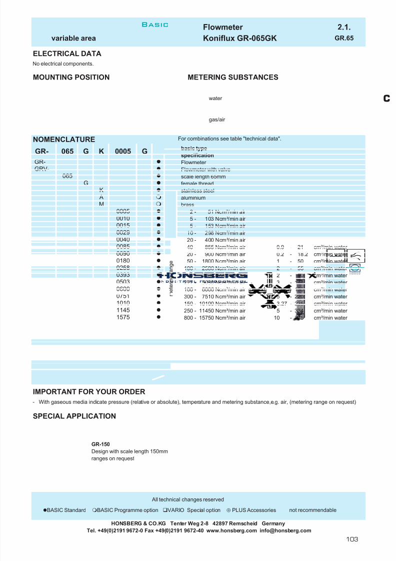
7/22/2019 General Honsberg
http://slidepdf.com/reader/full/general-honsberg 105/347
Flowmeter 2.1.variable area Koniflux GR-065GK GR.65
ELECTRICAL DATA
MOUNTING POSITION METERING SUBSTANCES
water
gas/air
NOMENCLATURE For combinations see table "technical data".
basic typespecificationFlowmeter Flowmeter with valvescale length 65mmfemale threadstainless steelaluminiumbrass
2 - 51 Ncm³/min air 5 - 103 Ncm³/min air 5 - 153 Ncm³/min air
10 - 298 Ncm³/min air 20 - 400 Ncm³/min air 40 - 855 Ncm³/min air 0.9 - 21 cm³/min water 20 - 900 Ncm³/min air 0.2 - 18.2 cm³/min water 50 - 1800 Ncm³/min air 1 - 50 cm³/min water
100 - 2580 Ncm³/min air 2 - 55 cm³/min water 100 - 3930 Ncm³/min air 2 - 90 cm³/min water 277 - 5030 Ncm³/min air 3 - 144 cm³/min water 100 - 6000 Ncm³/min air 2 - 130 cm³/min water 300 - 7510 Ncm³/min air 5 - 220 cm³/min water 150 - 10100 Ncm³/min air 3.27 - 235 cm³/min water 250 - 11450 Ncm³/min air 5 - 334 cm³/min water 800 - 15750 Ncm³/min air 10 - 375 cm³/min water 400 - 18960 Ncm³/min air 10 - 560 cm³/min water 700 - 23640 Ncm³/min air 10 - 570 cm³/min water
2000 - 29400 Ncm³/min air 40 - 880 cm³/min water 2000 - 43340 Ncm³/min air 50 -1305 cm³/min water glass floatstainless steel floatscale with direct range readingfloat saphire, tantal or carbonprecision valve
IMPORTANT FOR YOUR ORDER- With gaseous media indicate pressure (relative or absolute), temperature and metering substance,e.g. air, (metering range on request)
SPECIAL APPLICATION
GR-150Design with scale length 150mmranges on request
All technical changes reserved
BASIC Standard BASIC Programme option VARIO Special option ⊕ PLUS Accessories not recommendable
HONSBERG & CO.KG Tenter Weg 2-8 42897 Remscheid GermanyTel. +49(0)2191 9672-0 Fax +49(0)2191 9672-40 www.honsberg.com [email protected]
No electrical components.
0258
4334
0393
1010
2364
G
0040
GR-GR-GRV-
K
G
0005
1896
065
065
0005
1145
0090
00150029
050306000751
M A
G
K
2940
GK
Special optionVARIO
m
e t e r i n g r a n g e0180
0085
1575
0010
Basic
C
103

7/22/2019 General Honsberg
http://slidepdf.com/reader/full/general-honsberg 106/347
Flowmeter 2.3.variable area Visoflow VL VL.
GENERAL CHARACTERISTICS Female thread G1/2 to G1 stainless steel
TECHNICAL DATA
Metering range is indicated for vertical upward increasing flow.
tolerance ±5% of full scalemedia temperature max. 100°Caverage pressure loss 0.01-0.2 bar at Qmax.
MATERIALS
VL-...GA VL-...GKhousing aluminium anodized aluminium anodizedconnectors brass Ms58 stainless steel 1.4571
nickel platedglass duran 50 duran 50
float brass Ms58 stainless steel 1.4571nickel platedmagnet hardferrite hardferriteseal NBR viton dotted lines: switch head VLR-
HONSBERG & CO.KG Tenter Weg 2-8 42897 Remscheid GermanyTel. +49(0)2191 9672-0 Fax +49(0)2191 9672-40 www.honsberg.com [email protected]
32 0.630.65
41 1.0032
1717 41 1.00
43 73 135 13
32 0.6343 73 135 13 32 0.6343 73 135 13
1.0043 73 132 13 32 0.6350 76 184 17
0.6541 1.0041
50 76 184 17
0.6343 73 135 13 32 0.6343 73 135
0.6343 73 135 13 32 0.6343 73 132 13
VL-015GK008 10
18 2 - 18 43
50
VLR-015GA018
Flowmeter operates according to variable area principlewith a cylindrical float moving flow-dependendly in aconical metering tube.
good repeatabilityoptional with limit switch
VL-025GK035 10 35 3 - 35VL-025GK050 10
VL-015GK002 10 1,5 0.1 - 1.53 0.2 - 3
b r a s s
s t a i n l e s s s t e e l
G
G1/2
G1
G1/2
G1
VL-025GA0503550
10
1010
18
0.3 - 838
12
3 - 35
Type Qmax. recom.l/min H 2O
metering rangel/min H 2O
10 1,5
2 - 18 43
VL-015GK003 10
4 - 5010VL-025GA035
0.2 - 3
1 - 121010VL-015GA018
VL-015GA003VL-015GA008VL-015GA012
8 0.3 - 8VL-015GK012 10 12 1 - 12VL-015GK018 10
Lmm
163
Hmm
77
Dmm
PNbar
VL-015GA002 0.1 - 1.5
Xmm
13
AFmm
32
32
3213
4 - 50
77 163 13
50 76 18450 76 184
weightkg
Basic
104

7/22/2019 General Honsberg
http://slidepdf.com/reader/full/general-honsberg 107/347
Flowmeter 2.3.variable area Visoflow VL VL.
ELECTRICAL DATA reed switch - wiring 0.212 n.o.230 V AC 1 A 50 VADN 15 plug DIN 43650-C
No electrical components DN 25 plug DIN 43650-Aadjustable range complies to metering rangeprotection class IP 65
additional weight 0.02kgMOUNTING POSITION METERING SUBSTANCES
water gas/air
design stainless steel VL-...GKoil for aggressive liquids
NOMENCLATURE For combination see table "technical data"
basic typespecificationFlowmeter Flowmeter with switch headnominal diameter DN 15 - G1/2nominal diameter DN 25 - G1female threadmanifold block connector for 70.1.VB.connector material brassconnector material stainless steel0.1 - 1.5 l/min0.2 - 3 l/min0.3 - 8 l/min1 - 12 l/min2 - 18 l/min3 - 35 l/min4 - 50 l/minwiring 0.342 - change over
BASICsetting / ranges for oil or gas
VARIO scale 0 - 100%special scale, special ranges
IMPORTANT FOR YOUR ORDER- Please indicate metering substance and metering range with your order.- With viscous liquids please indicate viscosity, temperature and metering substance ( metering range on request)- With gaseous media indicate pressure (relative or absolute), temperature and metering substance ( metering range on request)
All technical changes reserved
lBASIC Standard BASIC Programme option VARIO Special option ⊕ PLUS Accessories not recommendable
HONSBERG & CO.KG Tenter Weg 2-8 42897 Remscheid GermanyTel. +49(0)2191 9672-0 Fax +49(0)2191 9672-40 www.honsberg.com [email protected]
Special option
VL- 015 G A
B A S I C
P r o g r a m m e
o p t i o n
VL-VLR-
015
G025
m e t e r i n g r a n g e
H 2
O
002
K
W A
012
002
035050
003008
018
BASIC Standard
Programme option
1 2
Basic
C
105

7/22/2019 General Honsberg
http://slidepdf.com/reader/full/general-honsberg 108/347
Flowmeter 2.1.variable area Koniflux UK-020 UK.20
GENERAL CHARACTERISTICS Female thread NPT1/8" brass/stainless steel
UKV-020GML0005TECHNICAL DATA
tolerance ±5% of full scalemedia temperature max. 65°C
MATERIALS
UK-020GM UK-020GKhousing acrylic acrylicfloat glass/stainless steel glass/stainless steelbuffers stainless steel stainless steelconnectors brass stainless steelseal NBR vitonvalve brass/NBR stainless steel/viton
HONSBERG & CO.KG Tenter Weg 2-8 42897 Remscheid GermanyTel. +49(0)2191 9672-0 Fax +49(0)2191 9672-40 www.honsberg.com [email protected]
Qmax. recom.
UK.-020G.W0100UK.-020G.W0240
0.13
0.13
a i r
NPT 1/8"
UK.-020G.L0025
UK.-020G.W0003
66
UK.-020G.W0080UK.-020G.L0000UK.-020G.L0001UK.-020G.L0005
UK.-020G.W0006
UK.-020G.W0040
H 2
O
weightkg
6 l/min66
6
metering range
---
5
6 l/min
66
66 6 l/min
6 l/min0.7 Nl/min1.2 Nl/min
6
6 l/min6 l/min
6 l/min6 l/min
NPT PNbar
6NPT 1/8"
6
Type
UK.-020G.W0050
UK.-020G.W0015
1020
50100240
3---
615
0.1
0.2
0.04-
0.514
10
--
---
4080
5
l/hNl/minNl/min
0,51
cm³/mincm³/mincm³/minl/hl/hl/hl/h
Nl/minNl/min
0.42
6.0 Nl/min30.0 Nl/min 25
Flowmeter operates according to the variable areaprinciple with a ball float moving flow-dependendly in aconical metering tube.
full face scale printoptional adjustment valve
Basic
106

7/22/2019 General Honsberg
http://slidepdf.com/reader/full/general-honsberg 109/347
Flowmeter 2.1.variable area Koniflux UK-020 UK.20
ELECTRICAL DATA
No electrical components.
MOUNTING POSITION METERING SUBSTANCES
water
gas/air
NOMENCLATURE For combinations see table "technical data".
basic typespecificationFlowmeter Flowmeter with valveinstrument series 020 , NPT 1/8"female threadbrassstainless steel
5 - 50 cm³/min10 - 100 cm³/min20 - 240 cm³/min
0.2 - 3 l/h0.5 - 6 l/h1 - 15 l/h4 - 40 l/h
10 - 80 l/h0.04 - 0.5 Nl/min0.1 - 1 Nl/min0.4 - 5 Nl/min2.0 - 25 Nl/min
seal Vitonspecial scales
IMPORTANT FOR YOUR ORDER- With gaseous media indicate pressure (relative or absolute), temperature and metering substance, e.g. air (metering range on request)
All technical changes reserved
lBASIC Standard BASIC Programme option VARIO Special option ⊕ PLUS Accessories not recommendable
W0006
W0040
m e t e r i n g
r a n g e
a i r
m e t e r i n g r a n g e
H 2
O
L0001L0005L0025
W0050W0100
W0080
W0240W0003
GUK-UKV-
UK- 020 M
020
W0015
G
VARIOSpecial option
K
L0000
M
W0050
HONSBERG & CO.KG Tenter Weg 2-8 42897 Remscheid GermanyTel. +49(0)2191 9672-0 Fax +49(0)2191 9672-40 www.honsberg.com [email protected]
Basic
C
107

7/22/2019 General Honsberg
http://slidepdf.com/reader/full/general-honsberg 110/347
Flowmeter 2.1.variable area Koniflux UK-040 UK.40
GENERAL CHARACTERISTICS Female thread NPT1/8" brass/stainless steel
UKV-040GML0010TECHNICAL DATA
tolerance ±3% of full scalemedia temperature max. 65°C
MATERIALS
UK-040GM UK-040GKhousing acrylic acrylicfloat glass/stainless steel glass/stainless steelbuffers stainless steel stainless steelconnectors brass stainless steelseal NBR vitonvalve brass/NBR stainless steel/viton
HONSBERG & CO.KG Tenter Weg 2-8 42897 Remscheid GermanyTel. +49(0)2191 9672-0 Fax +49(0)2191 9672-40 www.honsberg.com [email protected]
24.0 Nl/min36.0 Nl/min
12.0 Nl/min6.0 Nl/min
60.0 Nl/min120.0 Nl/min
a i r
NPT 1/8" UK.-040G.L0001 1.2 Nl/min
l/h0.2 - 3l/h
0.240.6 - 81 - 144 - 408 - 80
0.24
Nl/min
l/h
UK.-040G.L0100
UK.-040G.L0010UK.-040G.L0005
UK.-040G.L0030UK.-040G.L0050
6
6 l/min
6 6 l/min
6 l/min6 l/min
UK.-040G.W0008 6UK.-040G.W0014 6
weightkg
H 2
O
6
NPT Type PNbar
NPT 1/8" UK.-040G.W0003 6
UK.-040G.W00406 6 l/min
UK.-040G.W0220 6 l/min
6
666 Nl/min
Nl/min
l/hl/hl/h
Nl/minNl/minNl/minNl/min
10 - 100
20 - 2200.1 - 10.4 - 51 - 10
Flowmeter operates according to the variable areaprinciple with a ball float moving flow-dependendly in aconical metering tube.
full face scale printoptional adjustment valve
2 - 203 - 304 - 50
66
UK.-040G.L0020
UK.-040G.W0080
Qmax. recom. metering range
Basic
108
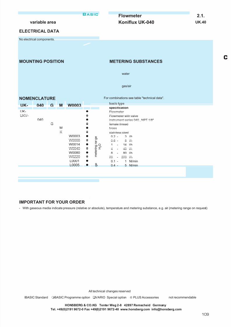
7/22/2019 General Honsberg
http://slidepdf.com/reader/full/general-honsberg 111/347
Flowmeter 2.1.variable area Koniflux UK-040 UK.40
ELECTRICAL DATA
No electrical components.
MOUNTING POSITION METERING SUBSTANCES
water
gas/air
NOMENCLATURE For combinations see table "technical data".
basic typespecificationFlowmeter Flowmeter with valveinstrument series 040 , NPT 1/8"female threadbrassstainless steel
0.2 - 3 l/h0.6 - 8 l/h1 - 14 l/h4 - 40 l/h8 - 80 l/h
20 - 220 l/h0.1 - 1 Nl/min0.4 - 5 Nl/min1 - 10 Nl/min2 - 20 Nl/min3 - 30 Nl/min4 - 50 Nl/min
10 - 100 Nl/minseal Vitonspecial scales
IMPORTANT FOR YOUR ORDER- With gaseous media indicate pressure (relative or absolute), temperature and metering substance, e.g. air (metering range on request)
All technical changes reserved
lBASIC Standard BASIC Programme option VARIO Special option ⊕ PLUS Accessories not recommendable
HONSBERG & CO.KG Tenter Weg 2-8 42897 Remscheid GermanyTel. +49(0)2191 9672-0 Fax +49(0)2191 9672-40 www.honsberg.com [email protected]
L0050
W0003W0008W0014W0040W0080W0220L0001L0005L0010L0020L0030
L0100
UKV-
UK-
040
UK-
040 M
m e t e r i n g r a n g e
H 2
O
m e t e r i n g r a n g e
a i r
VARIOSpecial option
G W0003
MK
G
Basic
C
109

7/22/2019 General Honsberg
http://slidepdf.com/reader/full/general-honsberg 112/347
Flowmeter 2.1.variable area Koniflux UK-044 UK.44
GENERAL CHARACTERISTICS male thread NPT1/4" PVC
UK-044AHW0050TECHNICAL DATA
tolerance ±5% of full scalemedia temperature max. 65°C
MATERIALS
housing acrylicfloat aluminuimbuffers stainless steelconnectors PVCseal NBR
HONSBERG & CO.KG Tenter Weg 2-8 42897 Remscheid GermanyTel. +49(0)2191 9672-0 Fax +49(0)2191 9672-40 www.honsberg.com [email protected]
30200
weightkg
0.1
0.1---
--
metering range
l/hl/hl/h
50100230
-415
6666
H 2
O
a i r
NPT
NPT 1/4"
NPT 1/4"
Type
UK-044AHW0050UK-044AHW0100UK-044AHW0230
Nl/h30008500
5001000
66
PNbar
Flowmeter operates according to the variable areaprinciple with a ball float moving flow-dependendly in aconical metering tube.
full face scale print
UK-044AHL1700UK-044AHL3000UK-044AHL8500 Nl/h
1700 Nl/h
Basic
110

7/22/2019 General Honsberg
http://slidepdf.com/reader/full/general-honsberg 113/347
Flowmeter 2.1.variable area Koniflux UK-044 UK.44
ELECTRICAL DATA
No electrical components.
MOUNTING POSITION METERING SUBSTANCES
water
gas/air
NOMENCLATURE For combinations see table "technical data".
basic typespecificationFlowmeter instrument series 044 , male thread NPT 1/4"male threadPVC
4 - 50 l/h water 15 - 100 l/h water 30 - 230 l/h water
100 - 1700 Nl/h air 500 - 3000 Nl/h air
1000 - 8500 Nl/h air seal Vitonspecial scales
IMPORTANT FOR YOUR ORDER
- With gaseous media indicate pressure (relative or absolute), temperature and metering substance, e.g. air (metering range on request)
All technical changes reserved
BASIC Standard BASIC Programme option VARIO Special option ⊕ PLUS Accessories not recommendable
L3000L8500
L1700
A
UK-
VARIO
m e t e r i n g
r a n g e
044
W0100W0230
W0050
H W0050
Special option
UK- 044 A
H
HONSBERG & CO.KG Tenter Weg 2-8 42897 Remscheid GermanyTel. +49(0)2191 9672-0 Fax +49(0)2191 9672-40 www.honsberg.com [email protected]
Basic
C
111

7/22/2019 General Honsberg
http://slidepdf.com/reader/full/general-honsberg 114/347
Flowmeter 2.3.variable area Koniflux UK-047 UK.47
GENERAL CHARACTERISTICS female thread NPT1/2" PVC
UK-047GHL0070TECHNICAL DATA
tolerance ±3% of full scalemedia temperature max. 65°C
MATERIALS
housing acrylicfloat aluminuim / stainless steelconnectors PVCseal NBR
HONSBERG & CO.KG Tenter Weg 2-8 42897 Remscheid GermanyTel. +49(0)2191 9672-0 Fax +49(0)2191 9672-40 www.honsberg.com [email protected]
6
UK-047GHL0034
UK-047GHL0150
NPT
NPT 1/2"
NPT 1/2"
PNbar
666 240
Nl/hNl/hNl/h-
4200090000
---
l/min120120
--
60012002400
20400
Flowmeter operates according to variable area principlewith a cylindrical float moving flow-dependendly in aconcical metering tube.
dual scale LPM and LPHfull face scale print
224
80100150
l/minNl/minNl/minNl/min
a i r
H 2
O
--
metering rangedual scale LPM and LPH
l/hl/hl/h40
weightkg
0.35
0.35-
--
-
1020
l/min
Type
UK-047GHW0010UK-047GHW0020UK-047GHW0040
480060009000
UK-047GHL0070340700
1500
66
Basic
112

7/22/2019 General Honsberg
http://slidepdf.com/reader/full/general-honsberg 115/347
Flowmeter 2.3.variable area Koniflux UK-047 UK.47
ELECTRICAL DATA
No electrical components.
MOUNTING POSITION METERING SUBSTANCES
water
gas/air
NOMENCLATURE For combinations see table "technical data".
basic typespecificationFlowmeter instrument series 047 , female thread NPT 1/2"female threadPVC
2 - 10 l/min water 120 - 600 l/h water 2 - 20 l/min water 120 - 1200 l/h water 3 - 40 l/min water 240 - 2400 l/h water
80 - 340 Nl/min air 4800 - 20400 Nl/h air 100 - 700 Nl/min air 3600 - 36000 Nl/h air 150 - 1500 Nl/min air 2000 - 72000 Nl/h air seal Vitonspecial scales
IMPORTANT FOR YOUR ORDER
- With gaseous media indicate pressure (relative or absolute), temperature and metering substance, e.g. air (metering range on request)
All technical changes reserved
lBASIC Standard BASIC Programme option VARIO Special option ⊕ PLUS Accessories not recommendable
HONSBERG & CO.KG Tenter Weg 2-8 42897 Remscheid GermanyTel. +49(0)2191 9672-0 Fax +49(0)2191 9672-40 www.honsberg.com [email protected]
L0150
W0010
H
VARIOSpecial option
G047
GUK-
UK- 047
W0010W0020
m e t e r i n g
r a n g e
L0070L0034W0040
H
Basic
C
113

7/22/2019 General Honsberg
http://slidepdf.com/reader/full/general-honsberg 116/347
Flowmeter 2.3.variable area Koniflux UK-048 UK.48
GENERAL CHARACTERISTICS female thread NPT3/4" PVC
UK-048GHW0045TECHNICAL DATA
tolerance ±3% of full scalemedia temperature max. 65°C
MATERIALS
housing acrylicfloat aluminuim / stainless steelconnectors PVCseal NBR
HONSBERG & CO.KG Tenter Weg 2-8 42897 Remscheid GermanyTel. +49(0)2191 9672-0 Fax +49(0)2191 9672-40 www.honsberg.com [email protected]
Type
H 2
OUK-048GHW0045UK-048GHW0060UK-048GHW0070
a i r
1200012000
Nl/min2200
45
200
-568
150200
Nl/min
Flowmeter operates according to variable area principlewith a cylindrical float moving flow-dependendly in aconcical metering tube.
dual scale LPM and LPHfull face scale print
NPT
NPT 3/4"
NPT 3/4"
-
6070
14001800
----
9000
l/minl/minl/minNl/min
--
300360480
Nl/hNl/h
-
270036004200
84000108000132000
-
Nl/h
PNbar
666
l/hl/hl/h
--
weightkg
0.45
0.45UK-048GHL0140UK-048GHL0180UK-048GHL0220
666
metering rangedual scale LPM and LPH
Basic
114
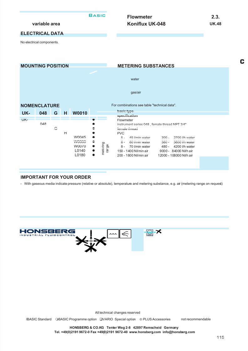
7/22/2019 General Honsberg
http://slidepdf.com/reader/full/general-honsberg 117/347
Flowmeter 2.3.variable area Koniflux UK-048 UK.48
ELECTRICAL DATA
No electrical components.
MOUNTING POSITION METERING SUBSTANCES
water
gas/air
NOMENCLATURE For combinations see table "technical data".
basic typespecificationFlowmeter instrument series 048 , female thread NPT 3/4"female threadPVC
5 - 45 l/min water 300 - 2700 l/h water 6 - 60 l/min water 360 - 3600 l/h water 8 - 70 l/min water 480 - 4200 l/h water
150 - 1400 Nl/min air 9000 - 84000 Nl/h air 200 - 1800 Nl/min air 12000 - 108000 Nl/h air 200 - 2200 Nl/min air 12000 - 132000 Nl/h air seal Vitonspecial scales
IMPORTANT FOR YOUR ORDER
- With gaseous media indicate pressure (relative or absolute), temperature and metering substance, e.g. air (metering range on request)
All technical changes reserved
lBASIC Standard BASIC Programme option VARIO Special option ⊕ PLUS Accessories not recommendable
HONSBERG & CO.KG Tenter Weg 2-8 42897 Remscheid GermanyTel. +49(0)2191 9672-0 Fax +49(0)2191 9672-40 www.honsberg.com [email protected]
H
L0180
W0045
m e t e r i n g
r a n g e
L0140
L0220
W0060W0070
UK-
UK- 048
048G
G
VARIOSpecial option
W0010
H
Basic
C
115
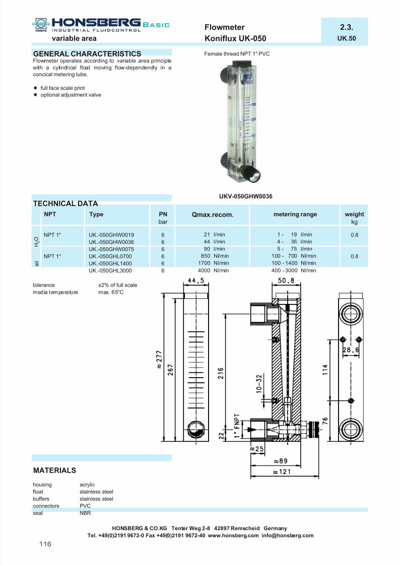
7/22/2019 General Honsberg
http://slidepdf.com/reader/full/general-honsberg 118/347
Flowmeter 2.3.variable area Koniflux UK-050 UK.50
GENERAL CHARACTERISTICS Female thread NPT 1" PVC
UKV-050GHW0036TECHNICAL DATA
tolerance ±2% of full scalemedia temperature max. 65°C
MATERIALS
housing acrylicfloat stainless steelbuffers stainless steelconnectors PVCseal NBR
HONSBERG & CO.KG Tenter Weg 2-8 42897 Remscheid GermanyTel. +49(0)2191 9672-0 Fax +49(0)2191 9672-40 www.honsberg.com [email protected]
1700 Nl/min4000 Nl/min
21 l/min44 l/min90 l/min
850 Nl/min
400 - 3000 Nl/min
weightkg
5 - 75
Flowmeter operates according to variable area principlewith a cylindrical float moving flow-dependendly in aconcical metering tube.
full face scale printoptional adjustment valve
0.8
6
a i r
100 - 700 Nl/min100 - 1400 Nl/min
0.8
NPT Type PNbar
NPT 1"
Qmax.recom. metering range
H 2
O
NPT 1"
1 - 196
6666
4 - 36 l/minl/min
UK.-050GHW0019UK.-050GHW0036UK.-050GHW0075UK.-050GHL0700UK.-050GHL1400UK.-050GHL3000
l/min
Basic
116

7/22/2019 General Honsberg
http://slidepdf.com/reader/full/general-honsberg 119/347
Flowmeter 2.3.variable area Koniflux UK-050 UK.50
ELECTRICAL DATA
No electrical components.
MOUNTING POSITION METERING SUBSTANCES
water
gas/air
NOMENCLATURE For combinations see table "technical data".
basic typespecificationFlowmeter Flowmeter with valveinstrument series 050 , NPT 1"female threadPVC
1 - 19 l/min4 - 36 l/min5 - 75 l/min
100 - 700 Nl/min100 - 1400 Nl/min400 - 3000 Nl/minseal vitonspecial scales
IMPORTANT FOR YOUR ORDER- With gaseous media indicate pressure (relative or absolute), temperature and metering substance, e.g. air (metering range on request)
All technical changes reserved
lBASIC Standard BASIC Programme option VARIO Special option ⊕ PLUS Accessories not recommendable
HONSBERG & CO.KG Tenter Weg 2-8 42897 Remscheid GermanyTel. +49(0)2191 9672-0 Fax +49(0)2191 9672-40 www.honsberg.com [email protected]
G H W0019050
L3000 m e t e r i n g r a n g e
W0036
Soecial optionVARIO
a i r
H 2
O
050
UK-UK-
GH
L0700W0075
L1400
W0019
UKV-
Basic
C
117

7/22/2019 General Honsberg
http://slidepdf.com/reader/full/general-honsberg 120/347
Flowmeter 2.2.variable area Koniflux GK-...GT GK.
GENERAL CHARACTERISTICS Female thread Rp3/8 to Rp1cast iron
GK-010GTW0160PO
TECHNICAL DATA
GK-...G GK-...Mpressure PN15 Measurements on requesttolerance ±1% of full scale
and ±3% of measured valuemedia temperature max. 60°Cpressure loss max. 20mbar
MATERIALS
tube trogamidfloat polypropyleneconnector cast ironseal viton
HONSBERG & CO.KG Tenter Weg 2-8 42897 Remscheid GermanyTel. +49(0)2191 9672-0 Fax +49(0)2191 9672-40 www.honsberg.com [email protected]
6,0bar
11 9,7 8,5 7,7- - -
polysulfon 15 15 15 14 13 12
100trogamid 15 15 15 13,5 12 10,7 9,5 -
60 70 80 9020 30 40 50
-
---
40 - 40050 - 650
5 - 60
10 - 100
20 - 25040 - 400
0.18
0.30
0.50
0.65
0.18
0.30
0.50
0.65
1 1/2
Nm³/h1 - 16 2 - 16 Nm³/h
--
--0.4 - 4
GK-025GTL0160
Rp 1
temperature °Ctube -20 0
-
19GK-025GTL0060 0.5 - 6 - Nm³/hGK-025GTL0100 1 - 10
250GK-025GTL0040 Nm³/h
16GK-020GTL0037 0.25- 3.75 - Nm³/hGK-020GTL00.. 0.5 - 5.5
230
Nm³/h
1 - 10
55
0.2 - 2.5 - Nm³/h- 50
219 200-
185 41
201 185 1 1/4GK-015GTL0048 0.4 - 4.8 - Nm³/h-
- Nl/h 207
-
Nm³/h-
- - 215
0.75- 6.5
3/4
1
32 12
13
GK-010GTL0550 50 - 550 - Nl/hGK-010GTL0900 100 - 900
Nm³/h-
Nl/h- Nm³/h-
-
165
170Rp 1/2 GK-015GTL0038 0.4 - 3.8
GK-020GTL0025
180
a i r
Rp 3/8 GK-010GTL0360 20 - 360
GK-010GTL0015 0.15- 1.5GK-010GTL0024 0.2 - 2.4
Rp 3/4
19l/h 250 219
l/h
200 1 1/2 55l/h
H 2
O
GK-025GTW06.. 60 - 640GK-025GTW0400
Rp 1 GK-025GTW0250 20 - 250 20 - 250
60 - 64040 - 400 40 - 400
GK-020GTW06.. 60 - 640 60 - 640 l/h60 - 600
50 16GK-020GTW0250 20 - 250 20 - 250 l/hGK-020GTW0400 40 - 400
230 201 185 1 1/415 - 160 15 - 160 l/h-
40 - 400 l/h
41 13GK-015GTW0250 20 - 250 20 - 250 l/h
15 - 16020 - 250
215 185 170 1l/h
Rp 1/2 GK-015GTW0160 15 - 160 15 - 160 l/h15 - 160
3/4 12GK-010GTW0040 2 - 40 2 - 40 l/hGK-010GTW0060 5 - 60 5 - 60
180 165 322 - 25 l/h 207
l/h
10 - 100 l/h15 - 160
-4 - 40
2 - 25
GK-010GTW0100 10 - 100GK-010GTW0160 15 - 160
Rp 3/4 GK-020GTW0160
SWmm
Xmmpolypropylene
without magnet with magnet
Rp 3/8 GK-010GTW0025
metering range - floatstainless steelwithout/with magnet
weightkg
Lmm
L1mm
L2mm
G
Flowmeter operates according to variable area principlewith a cylindrical float moving flow-dependendly in aconical plastic tube.
comfortable scale reading with good resolutionactual flow rate indicator min/max
Rp Type
Basic
118

7/22/2019 General Honsberg
http://slidepdf.com/reader/full/general-honsberg 121/347
Flowmeter 2.2.variable area Koniflux GK-...GT GK.
ELECTRICAL DATA
No electrical components. Switch units or continuous signal converters see description next page
MOUNTING POSITION METERING SUBSTANCES
water
gas/air NOMENCLATURE For combinations see table "technical data".
basic typespecificationnominal diameter DN 10 - Rp3/8nominal diameter DN 15 - Rp1/2nominal diameter DN 20 - Rp3/4nominal diameter DN 25 - Rp1female thread Rp cast iron, PN15threaded connector with glue fittings PVC, PN10measuring tube trogamidmeasuring tube polysulfon (max. temperature 100°C)
2 - 25 l/h2 - 40 l/h4 - 40 l/h5 - 60 l/h
10 - 100 l/h
40 - 400 l/h60 - 600 l/h60 - 640 l/h50 - 650 l/h20 - 360 Nl/h50 - 550 Nl/h
100 - 900 Nl/h0.15- 1.5 Nm²/h0.2 - 2.4 Nm²/h0.2 - 2.5 Nm²/h0.25- 3.75 Nm²/h0.4 - 3.8 Nm²/h0.4 - 4 Nm²/h0.4 - 4.8 Nm²/h0.5 - 5.5 Nm²/h0.5 - 6 Nm²/h0.75- 6.5 Nm²/h1 - 10 Nm²/h1 - 16 Nm²/h2 - 16 Nm²/hfloat polypropylene without magnetfloat polypropylene with magnetfloat stainless steel without magnetfloat stainless steel with magnetscale in %actual metering ranges referring to pressure and temperaturespecial scalesswitch unitcontin.signal convert.
IMPORTANT FOR YOUR ORDER- With gaseous media indicate pressure (relative or absolute), temperature and metering substance, e.g. air (metering range on request)
All technical changes reserved
BASIC Standard BASIC Programme option VARIO Special option ⊕ PLUS Accessories not recommendable
HONSBERG & CO.KG Tenter Weg 2-8 42897 Remscheid GermanyTel. +49(0)2191 9672-0 Fax +49(0)2191 9672-40 www.honsberg.com [email protected]
Only for float with magnet.Description see next page.
Special option VARIO
Accessories PLUS ⊕
KMPro ramme o tion BASIC
PMKO
PO
L0160
L0100L0065L0060L0055L0048L0040L0038L0037L0025L0024L0015
L0360
a i r
L0550L0900
W0650 W0640
W0600 W0400
W0250 20 - 250 l/h
W0060 W0040
010 G TGK- W0025 PO010
BASIC Standard ⊕ PLUS accessories
M
15 - 160 l/h
W0100
W0160
015020025
G
TP
W0025
m e t e r i n g r a n g e
H 2
O
Basic
C
119

7/22/2019 General Honsberg
http://slidepdf.com/reader/full/general-honsberg 122/347
Flowmeter 2.2.variable area Koniflux GK-...GT GK.
ACCESSORIES
for DN 10-20maximum switch unit plasticbistable reed switchwiring diagram 0.212 n.o.250 V AC 0.2 A 10 VAplug DIN 43650-Bprotection class IP 65additional weight 0.035 kg
for DN 10-20minimal switch unit plasticbistable reed switchwiring diagram 0.214 n.c.250 V AC 0.2 A 10 VAplug DIN 43650-Bprotection class IP 65additional weight 0.035 kg
for DN 25maximum switch unit plasticbistable reed switchwiring diagram 0.212 n.o.250 V AC 0.2 A 10 VAplug DIN 43650-Bprotection class IP 65additional weight 0.075 kg
for DN 25minimal switch unit plasticbistable reed switchwiring diagram 0.214 n.c.250 V AC 0.2 A 10 VAplug DIN 43650-Bprotection class IP 65additional weight 0.075 kg
continuous signal converter plasticreed switch chain24 V DCexit signal: 0 - 10 k-Ohmplug DIN 43650-Bprotection class IP 65additional weight 0.07 kg
Type GKI-1273 for DN10-20Type GKI-1273-1 for DN25continuous signal converter plasticreed switch chain with integrated signal convertor supply11-40 V DC depending on ohmic resistanceohmic resistance max. 1500 Ω
exit signal: 4 - 20 mAplug DIN 43650-Bprotection class IP 65additional weight 0.08 kg
All technical changes reserved
BASIC Standard BASIC Programme option VARIO Special option ⊕ PLUS Accessories not recommendable
HONSBERG & CO.KG Tenter Weg 2-8 42897 Remscheid GermanyTel. +49(0)2191 9672-0 Fax +49(0)2191 9672-40 www.honsberg.com [email protected]
⊕ GKK-1271
⊕ GKEL-1252
⊕ GKEL-1257
⊕ GKI-1273 / GKI-1273-1
⊕ GKEH-1256
⊕ GKEH-1251
1 2
1 2
1 2
1 2
0 500 1000 150010
20
30
40
Ω
burden
voltage
123
1
2
U
J
Basic
120

7/22/2019 General Honsberg
http://slidepdf.com/reader/full/general-honsberg 123/347
Flowmeter 2.2.variable area Koniflux GKL-...GT GKL.
GENERAL CHARACTERISTICS Female thread Rp1 to Rp2 cast iron
GKL-050GTW0064PO
TECHNICAL DATA
GKL-...G GKL-...Mpressure PN15 Measurements on requesttolerance ±1% of full scale
and ±3% of measured valuemedia temperature max. 60°Cpressure loss max. 20mbar
MATERIALS
tube trogamidfloat polypropyleneconnector cast ironseal viton
HONSBERG & CO.KG Tenter Weg 2-8 42897 Remscheid GermanyTel. +49(0)2191 9672-0 Fax +49(0)2191 9672-40 www.honsberg.com [email protected]
bar 9,7 8,5 7,7 6,014 13 12 11polysulfon 15 15 15
- - - -13,5 12 10,7 9,5trogamid 15 15 1570 80 90 10030 40 50 60tube -20 0 20
Flowmeter operates according to variable area principlewith a cylindrical float moving flow-dependendly in aconical plastic tube.
comfortable scale reading with good resolutionextended scale lengthactual flow rate indicator min/max
66
74 20
55 17350 1 1/2
350 2410 370
Nm³/hNm³/h
19Nm³/h
Nm³/h 414
24420
1 1/2 55
350 2 1/4
369
L2mm
G SWmm
Xmm
L1mm
-
-
-
402 369
372l/hl/h
-
--
-
-
-4 - 40
-
-
temperature °C
a i r
Rp 1 GKL-025GTL0100 1 - 10
Rp 1 1/4 GKL-032GTL0160GKL-032GTL0250 2 - 25GKL-032GTL0400 4 - 40
2.40
0.75
1.25
2.4
weightkg
0.751.25
1.75
metering range - floatstainless steelwithout/with magnet
H 2
O
Rp 1
-
0.6 - 6.4
Rp Type Lmmpolypropylene
without magnet with magnet
350GKL-025GTW1000 100 - 1000 100 - 1000 100 - 1000 17Rp 1 1/4 GKL-032GTW1000 100 - 1000 100 - 1000 l/h 410 370 350
l/h2 66 19
GKL-032GTW1600 150 - 1600 150 - 1600 l/h-
150 - 1600
Rp 1 1/2 GKL-040GTW1600 200 - 1600 200 - 1600GKL-040GTW2500 300 - 2500 300 - 2500GKL-040GTW3300 300 - 3300 300 - 3300
200 - 2500
0.6 - 6.4 0.6 - 6.4
l/h 414
-0.4 - 4
Rp 2 GKL-050GTW0025 0.2 - 2.5 0.2 - 2.5GKL-050GTW0040 0.4 - 4 0.4 - 4GKL-050GTW0064
m³/h 420 374m³/hm³/h
350 2 3/4 90 24
1.25- 10 Nm³/h 402
Nm³/h
---
- Nm³/h-
GKL-025GTL0160 1.5 - 16 1.5 - 16 Nm³/hGKL-025GTL0250 - 3 - 25
1.5 - 16
GKL-040GTL0600 - 5 - 60
GKL-032GTL0640 - 6 - 64-
GKL-040GTL0400 4 - 40372 350 2 1/4 74 20 1.75
Nm³/hGKL-040GTL0500 5 - 50 - Nm³/h
--
Nm³/hRp 2 GKL-050GTL0400 4 - 40 -
10 - 100 -
Nm³/h
Nm³/h
Rp 1 1/2 GKL-040GTL0250 2 - 25
GKL-050GTL0640 6 - 64 - Nm³/hGKL-050GTL1000
374
--
GKL-050GTL1500 - 15 - 160
90350 2 3/4
Nm³/hGKL-050GTL2500 - 20 - 250 Nm³/h
Basic
C
121

7/22/2019 General Honsberg
http://slidepdf.com/reader/full/general-honsberg 124/347
Flowmeter 2.2.variable area Koniflux GKL-...GT GKL.
ELECTRICAL DATA
No electrical components. Switch units or continuous signal converterssee description next page
MOUNTING POSITION METERING SUBSTANCES
water
gas/air
NOMENCLATURE For combinations see table "technical data".
basic typespecificationnominal diameter DN 25 - Rp1nominal diameter DN 32 - Rp1 1/4nominal diameter DN 40 - Rp1 1/2nominal diameter DN 50 - Rp2female thread Rp cast iron, PN15threaded connector with glue fittings PVC, PN10measuring tube trogamidmeasuring tube polysulfon (max. temperature 100°C)
150 - 1600 l/h200 - 1600 l/h200 - 2500 l/h300 - 2500 l/h300 - 3300 l/h
0,2 - 2,5 m³/h0,4 - 4 m³/h0,6 - 6,4 m³/h1 - 10 Nm³/h1,25- 10 Nm³/h
2 - 25 Nm³/h
5 - 50 Nm³/h5 - 60 Nm³/h
10 - 100 Nm³/h15 - 150 Nm³/h20 - 250 Nm³/hfloat polypropylene without magnetfloat polypropylene with magnetfloat stainless steel without magnetfloat stainless steel with magnetscale in %actual metering ranges referring to pressure and temperaturespecial scalesswitch unitcontin.signal convert.
IMPORTANT FOR YOUR ORDER- With gaseous media indicate pressure (relative or absolute), temperature and metering substance, e.g. air (metering range on request)
All technical changes reserved
BASIC Standard BASIC Programme option VARIO Special option ⊕ PLUS Accessories not recommendable
HONSBERG & CO.KG Tenter Weg 2-8 42897 Remscheid GermanyTel. +49(0)2191 9672-0 Fax +49(0)2191 9672-40 www.honsberg.com [email protected]
BASIC Standard
050040
025
G
032
⊕ PLUS accessories
W1000 POGKL- 025 G T
MTP
W1000
M e s s b e r e i c h
W1600
L0160
H 2
O
100 - 1000 l/h
W2500
W3300
W0025
W0040
W0064
L0100
L u f t
1,5 - 16 Nm³/h
L0250
3 - 25 Nm³/h
L0400 4 - 40 Nm³/h
L0500
L0600
L0640 6 - 64 Nm³/h
L1000
L1500
L2500
POPMKOKM
Programme option BASICSpecial option VARIO
Accessories PLUS ⊕ Only for float with magnet.Description see next page.
Basic
122

7/22/2019 General Honsberg
http://slidepdf.com/reader/full/general-honsberg 125/347
Flowmeter 2.2.variable area Koniflux GKL-...GT GKL.
ACCESSORIES
maximum switch unit plasticbistable reed switchwiring diagram 0.212 n.o.250 V AC 0.2 A 10 VAplug DIN 43650-Bprotection class IP 65additional weight 0.075 kg
minimal switch unit plasticbistable reed switchwiring diagram 0.214 n.c.250 V AC 0.2 A 10 VAplug DIN 43650-Bprotection class IP 65additional weight 0.075 kg
continuous signal converter plasticreed switch chain24 V DCexit signal: 0 - 10 k-Ohmplug DIN 43650-Bprotection class IP 65additional weight 0.07 kg
continuous signal converter plasticreed switch chain with integrated signal converter supply11-40 V DC depending on ohmic resistanceohmic resistance max. 1500 Ω
exit signal: 4 - 20 mAplug DIN 43650-Bprotection class IP 65additional weight 0.08 kg
All technical changes reserved
BASIC Standard BASIC Programme option VARIO Special option ⊕ PLUS Accessories not recommendable
⊕ GKK-1270
⊕ GKI-1272
⊕ GKEL-1252
⊕ GKEH-1251
HONSBERG & CO.KG Tenter Weg 2-8 42897 Remscheid GermanyTel. +49(0)2191 9672-0 Fax +49(0)2191 9672-40 www.honsberg.com [email protected]
1 2
1 2
123
0 500 1000 150010
20
30
40
Ω
burden
voltage
1
2
U
J
Basic
C
123

7/22/2019 General Honsberg
http://slidepdf.com/reader/full/general-honsberg 126/347
Honsberg & Co. KGTenter Weg 2-8 · 42897 Remscheid · GermanyP.O. Box 1103 69 · 42863 Remscheid · GermanyTel. +49(0)2191 9672-0 · Fax +49(0)2191 9672-40www.honsberg.com · [email protected]
Basic
124
l Accurate and reliable meteringand display by float
l Metering tube shielded by addi- tional protective tube
l Precision valve for extremely
accurate and leak-free flow con- trol and dosage
l Brass body with high-sheen finish
l Display pressure-compensated3.5 bar
l FDA approval
l Filter in the inlet
Special applications
Flow meter MMF
Flow meter for respiratory air and oxygen in medical applications.
Block assembly with one input and 2 or 3 outputs
The flow meters of the Med-Flow series have been specially developedfor use in medical environments. The devices provide an extremely accu-rate and reliable method of metering and dosing respiratory air oroxygen.
The sturdy brass base and LEXAN metering and protective tubes contri-bute to this performance. The precision stainless steel valve makes
exact setting and reliable blocking possible.The metering ranges have been designed for an operating pressure of3.5 bar. Other calibration is available on request.
l Ranges up to 15 l/minl Temperature max. 65 °Cl Pressure max. 6.9 barl Materials Lexan, brass, stainless steel, NBR
Type Range Oxygen Air Accuracy Nl/min Nl/min
MMF-003 0.125 - 3.5 + - 0.2MMF-008 0.25 - 8 + + 0.4MMF-015 0.5 - 15 + + 0.6

7/22/2019 General Honsberg
http://slidepdf.com/reader/full/general-honsberg 127/347125
l Full acrylic or glass body Õ optimal visibility
l Variety of float materials Õ versatility
l Guiding rod for float Õ stability
l Buffer spring Õ protection at max flow
ratel Full space scale print Õ good readability
l Optional valve integrated Õ regulation
Why to use a variable area instrumentBasic

7/22/2019 General Honsberg
http://slidepdf.com/reader/full/general-honsberg 128/347
Market segments
Application
l Oxygen generator
l Medical installation
l Dosage
l Welding
l Monitoring of oxygen supply or outputl Measurement of breathing airl Measurement of substances in mixing operationsl Monitoring of gas supplies during welding
Where to use a variable area instrument
Honsberg & Co. KGTenter Weg 2-8 · 42897 Remscheid · GermanyP.O. Box 1103 69 · 42863 Remscheid · GermanyTel. +49(0)2191 9672-0 · Fax +49(0)2191 9672-40www.honsberg.com · [email protected]
126
Basic

7/22/2019 General Honsberg
http://slidepdf.com/reader/full/general-honsberg 129/347127
Paddle
The technology
Flow-dependent paddle movement is transformed magnetically con-
tactless to adjustable contactsand/or pointer metering units.
Application
l Pump monitoringl Run dry protection
Advantages
l Nominal diameters DN 10 to DN 300l Low pressure lossl Dirt-resistant
Concept housing or direct installation
Nominal diameter 10 - 300
Connection female thread or stub-connection
PN 6 - 25
Max. temperature 120 °C
Signal threshold, optical display
Adjustable yes
Materials brass, stainless steel, plastic
Installation position horizontal, flow from below
Metering materials liquids or gases
Technical data
l Switchingl Metering
Contents
Paddle 128
dynamic flap 129
Device descriptions 131
D
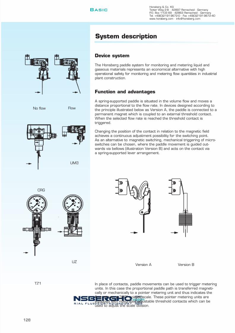
7/22/2019 General Honsberg
http://slidepdf.com/reader/full/general-honsberg 130/347
Honsberg & Co. KGTenter Weg 2-8 · 42897 Remscheid · GermanyP.O. Box 1103 69 · 42863 Remscheid · GermanyTel. +49(0)2191 9672-0 · Fax +49(0)2191 9672-40www.honsberg.com · [email protected]
Basic
128
System description
Device systemThe Honsberg paddle system for monitoring and metering liquid andgaseous materials represents an economical alternative with highoperational safety for monitoring and metering flow quantities in industrialplant construction.
Function and advantages
A spring-supported paddle is situated in the volume flow and moves adistance proportional to the flow rate. In devices designed according to
the principle illustrated below as Version A, the paddle is connected to apermanent magnet which is coupled to an external threshold contact.When the selected flow rate is reached the threshold contact is
triggered.
Changing the position of the contact in relation to the magnetic fieldachieves a continuous adjustment possibility for the switching point.As an alternative to magnetic switching, mechanical triggering of micro-switches can be chosen, where the paddle movement is guided out-wards via bellows (illustration Version B) and acts on the contact viaa spring-supported lever arrangement.
In place of contacts, paddle movements can be used to trigger meteringunits. In this case the proportional paddle path is transferred magneti-cally or mechanically to a pointer metering unit and thus indicates theflow rate on a 320° pointer scale. These pointer metering units areequipped with integrated adjustable threshold contacts which can beused to adjust the scale division.
TZ1
UZ
CRG
UM3
No flow Flow
Version A Version B

7/22/2019 General Honsberg
http://slidepdf.com/reader/full/general-honsberg 131/347
129
Metering materials and accuracy
Paddle devices are mainly used with liquid metering materials. The influ-ence of viscosity is lower compared to piston systems. The minimalintrusion of the free pipe diameter results in good dirt resistance and
minimum pressure losses. The screw-in devices can be used independ-ent of nominal diameters, with a selection possibility of certain paddlelengths which is simple to create using a segment paddle system(CM2K, CRE, UB1).
With air and gases, the functional ratio in relation to water is approx.1:15, i.e. 1 l/min of water corresponds to approx. 15 NI/min of air,whereby temperature, density and operating pressure play a special rolehere.
In these cases the devices are made according to customer specification.
We will be happy to provide advice where needed.
There are devices with additional soiling protection for the functionalparts available for soiled media.
Water Viscosity mm²/s
30 60 115 220UM/UR 4 4 3.8 3.5 3
8 8 7.6 7 6.610 10 9 8.5 820 20 19 18 17.5
CRG/UB1 60 58 55 53 4880 78 74 70 64
100 96 92 87 81120 117 111 107 96
Example:
Viscosity Flow rate
1 mm²/s 4.0 l/min115 mm²/s 3.5 l/min
D
Dynamic flap
The flowing liquids move a thin springy flap that covers theentire flow area. A magnet on the flap creates a changingmagnetic field, which is detected by a Hall sensor, when theflap is moved. Due to the spring-like quality of the flap and themolded stop, even strong impacts caused by the water areabsorbed well. The low number of parts that are touched by
the liquids ensure less contamination und smooth operation.
no flow flow
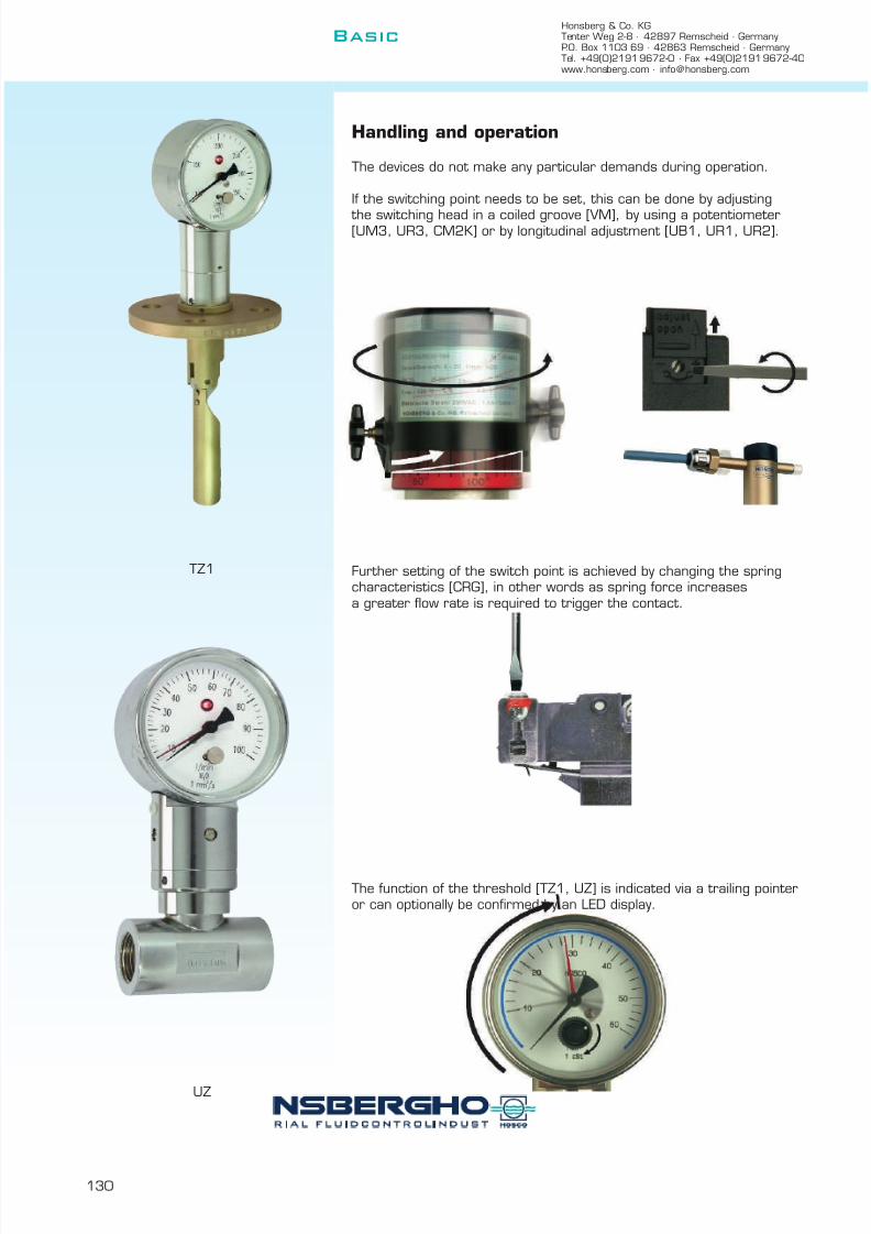
7/22/2019 General Honsberg
http://slidepdf.com/reader/full/general-honsberg 132/347
Basic
130
Handling and operation
The devices do not make any particular demands during operation.
If the switching point needs to be set, this can be done by adjusting
the switching head in a coiled groove [VM], by using a potentiometer[UM3, UR3, CM2K] or by longitudinal adjustment [UB1, UR1, UR2].
Further setting of the switch point is achieved by changing the springcharacteristics [CRG], in other words as spring force increasesa greater flow rate is required to trigger the contact.
The function of the threshold [TZ1, UZ] is indicated via a trailing pointeror can optionally be confirmed by an LED display.
TZ1
UZ
Honsberg & Co. KGTenter Weg 2-8 · 42897 Remscheid · GermanyP.O. Box 1103 69 · 42863 Remscheid · GermanyTel. +49(0)2191 9672-0 · Fax +49(0)2191 9672-40www.honsberg.com · [email protected]

7/22/2019 General Honsberg
http://slidepdf.com/reader/full/general-honsberg 133/347
131
m i s c e l l a n e o u s
p a g e
a g g r e s s
i v e
o i l
i n d i c a t i o n
t y p e
c o n t r o
l
c o n n e c t i o n
o u t p u t s i g n a
l
o n s
i t e m e t e r i n g
m a x . p r e s s u r e
b a r
m a x . t e m p e r a t u r e
° C
w a t e r
n o m
i n a
l d i a m e t e r
D
a i r / g a s
P a
d d l e
UR3K 10 - 50 female thread brass l 25 110 l 3 3 13210 - 50 female thread stainless steel l 25 110 l 3 3
15 - 80 soldering socket brass l 25 110 l 3 3 13415 - 80 welding socket stainless steel l 25 110 l 3 3
UMK3 10 - 50 female thread brass l 25 110 l 3 3 13610 - 50 female thread stainless steel l 25 110 l 3 3
15 - 80 soldering socket brass l 25 110 l 3 3 13815 - 80 welding socket stainless steel l 25 110 l 3 3
UR1/UR2 10 - 50 female thread brass l 25 110 l 3 3 14010 - 50 female thread stainless steel l 25 110 l 3 3
15 - 80 soldering / welding socket l 25 110 l 3 3 142
UI 10 - 50 female thread brass l 16 60 l 3 3 141
UB1 25-200 male thread brass l 16 140 l 3 14425-200 male thread stainless steel l 16 140 l 3 3
40-200 flange brass l 16 140 l 3
40-200 flange stainless steel l 16 140 l 3 3
CM2K 25-200 male thread brass l 25 110 l 3 14625-200 male thread stainless steel l 25 110 l 3
CRG 25-200 male thread brass l 11 110 l 3 m YR 14825-200 male thread stainless steel l 11 110 l 3 3
VM 40-200 flange brass l 16 90 l 3 15040-200 flange stainless steel l 16 90 l 3
TZ1 40-100 flange brass m l l 16 90 l 3 15240-100 flange stainless steel m l l 16 90 l 3
UZ 15 - 50 female thread brass m l l 6 100 l 3 15415 - 50 female thread stainless steel m l l 6 100 l 3 3
XF 8 - 20 female thread brass l l m 16 70 l 1568 - 20 female thread stainless steel l l m 16 70 l 3
8 - 20 female thread plasticl l m
16 70l
D y n a m
i c f l a
p
Honsbergcombi-nation
System
l standard m standard option special option all data sheets available under www.honsberg.com
HONSBERG & CO.KG Tenter Weg 2-8 42897 Remscheid GermanyTel. +49(0)2191 9672-0 Fax +49(0)2191 9672-40 www.honsberg.com [email protected]

7/22/2019 General Honsberg
http://slidepdf.com/reader/full/general-honsberg 134/347
Flow Switch 3.1.paddle Fluvatest UR3K-...GM/GK UR3K.G
GENERAL CHARACTERISTICS Female thread G3/8 to G2 brass/stainless steel
TECHNICAL DATA
Adjustable range is indicated for horizontally decreasing flow.
tolerance ±15% of full scalemedia temperature max. 110°Caverage pressure loss 0.01bar at Qmax.hysteresis depending on switch value
minimum 0.7 l/min.
MATERIALS
UR3K-...GM UR3K-...GKhousing brass Ms58 stainless steel 1.4305
nickel platedbody brass Ms58 stainless steel 1.4571
nickel platedpaddle stainless steel 1.4301 ; stainless steel 1.4301 ;
1.4571 1.4571spring stainless steel 1.4310 stainless steel 1.4310magnet oxyd 300 oxyd 300seal NBR viton
HONSBERG & CO.KG Tenter Weg 2-8 42897 Remscheid GermanyTel. +49(0)2191 9672-0 Fax +49(0)2191 9672-40 www.honsberg.com [email protected]
UR3K-015GM065
G 1/2
Type
UR3K-010GM050UR3K-015GM065UR3K-020GM085
UR3K-050GM690UR3K-010GK050G 3/8
G 2G 1 1/2
G
12 - 15
G 1 1/4 UR3K-032GM270UR3K-025GM150
100
10
40G 3/4
UR3K-040GM440
5 - 6.56 - 8.5
12 - 1520 - 2734 - 4425
96
Lmm
505050
1012
Xmm
10
1.001210
0.350.35
1212
0.350.400.550.60
G 1
Hmm
87878892
adjustable rangel/min H2O
3.5 - 5
weightkg
b r a s s
150
406080
G 1/2G 3/8
G 3/4
25
25
PNbar
10
Qmax.recom.l/min H2O
25 20
25
2525
12
50
54 - 69
505050
99
UR3K-015GK065UR3K-020GK085UR3K-025GK150
3.5 - 520
108
25
150UR3K-040GK440UR3K-050GK690
G 1
50 0.4010 0.4187 505 - 6.5
0.3512
1.00108 50 12G 2 25 s t a i n l e s s s t e e l
12
54 - 69100
0.5596 50 12
25
50
87
60 9288 506 - 8.5
2525
G 1 1/2 25UR3K-032GK270
0.7034 - 4420 - 2780
Instruments operate by a spring-supported paddel withmagnetic triggering of a reed switch.
good repeatabilitylow pressure loss
dirt resistanthermetic separation of electricaland hydraulic componentseasy adjustment of switch
99 50 12
0.45G 1 1/4 25
Basic
132

7/22/2019 General Honsberg
http://slidepdf.com/reader/full/general-honsberg 135/347
Flow Switch 3.1.paddle Fluvatest UR3K-...GM/GK UR3K.G
ELECTRICAL DATAreed switch - wiring 0.372 n.o.230 V AC 1A 50VAplug DIN 43650-Aprotection class IP 65
MOUNTING POSITION METERING SUBSTANCES
water gas/air
oil
NOMENCLATURE For combinations see table "technical data"
basic typespecificationDN 10 - G3/8DN 15 - G1/2DN 20 - G3/4DN 25 - G1DN 32 - G1 1/4DN 40 - G1 1/2DN 50 - G2female threadbrass designstainless steel design
3.5 - 5 l/min5 - 6.5 l/min6 - 8.5 l/min
12 - 15 l/min20 - 27 l/min34 - 44 l/min54 - 69 l/minsetting / adjustable ranges for oil or gascontact for locking plug M12x1, 4-poleminimal flow range
IMPORTANT FOR YOUR ORDER- Please indicate flow direction, metering substance and adjustable range with your order.- With viscous liquids please indicate viscosity, temperature and metering substance (adjustable range on request)- With gaseous media indicate pressure (relative or absolute), temperature and metering substance (adjustable range on request)
connection types for UR3K
All technical changes reserved
BASIC Standard BASIC Programme option VARIO Special option ⊕ PLUS Accessories not recommendable
HONSBERG & CO.KG Tenter Weg 2-8 42897 Remscheid GermanyTel. +49(0)2191 9672-0 Fax +49(0)2191 9672-40 www.honsberg.com [email protected]
M
050G
a d j u
s a b l e r a n g e
H 2 O h o r i z o n t a l
270
690440
150
065085
050K
040
020
032025
010
015010
UR3K- G M 050
n o m i n a l d i a m e t e r
Installation position mayinfluence switch value.
Special optionVARIO
HONSBERG COMBINATION SYSTEM
1 2
female thread male thread welding, soldering solder fitting glue fi ttingglue socketbrass brass copper PVC
brass, stainless steel, PVCPOMstainless steel
D
133
Basic
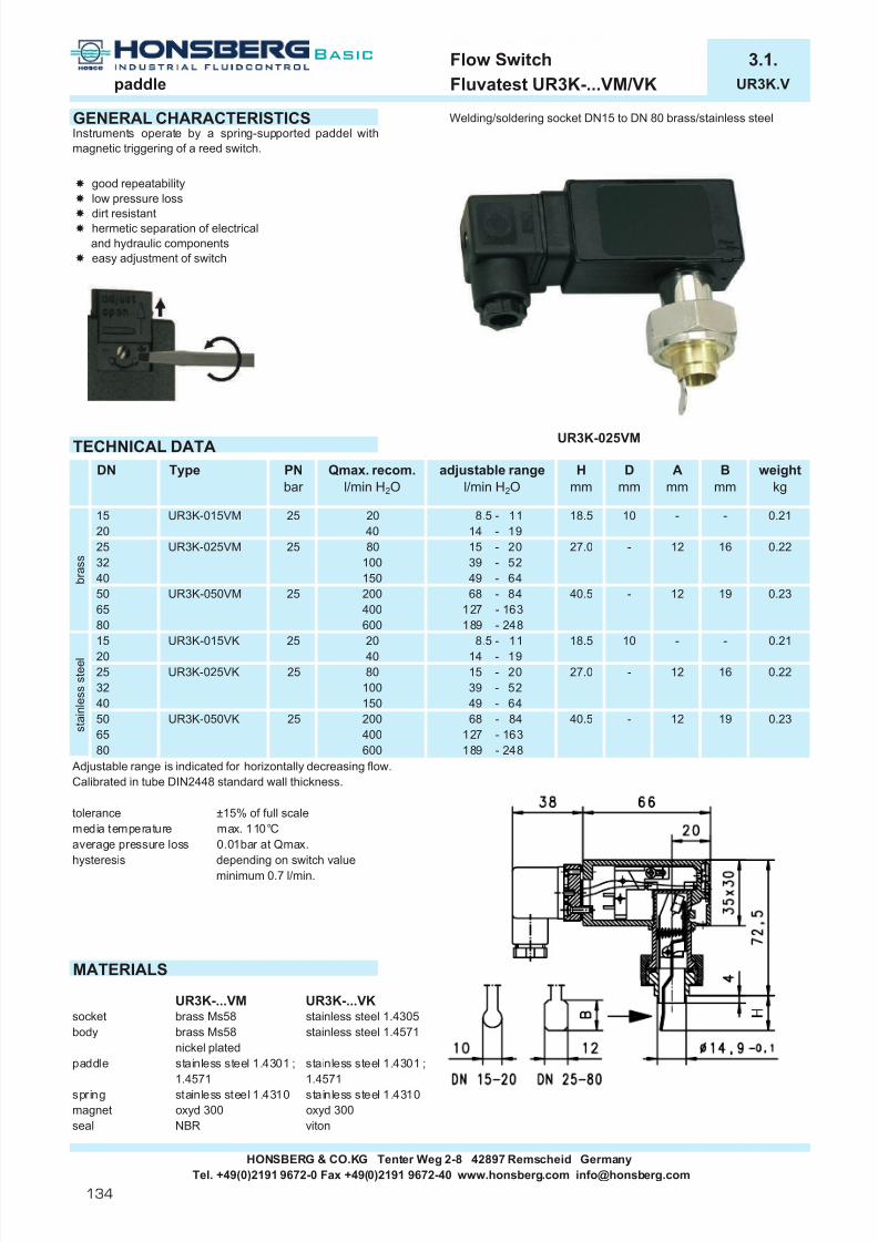
7/22/2019 General Honsberg
http://slidepdf.com/reader/full/general-honsberg 136/347
Flow Switch 3.1.paddle Fluvatest UR3K-...VM/VK UR3K.V
GENERAL CHARACTERISTICS Welding/soldering socket DN15 to DN 80 brass/stainless steel
TECHNICAL DATA
Adjustable range is indicated for horizontally decreasing flow.Calibrated in tube DIN2448 standard wall thickness.
tolerance ±15% of full scalemedia temperature max. 110°Caverage pressure loss 0.01bar at Qmax.hysteresis depending on switch value
minimum 0.7 l/min.
MATERIALS
UR3K-...VM UR3K-...VKsocket brass Ms58 stainless steel 1.4305body brass Ms58 stainless steel 1.4571
nickel platedpaddle stainless steel 1.4301 ; stainless steel 1.4301 ;
1.4571 1.4571spring stainless steel 1.4310 stainless steel 1.4310magnet oxyd 300 oxyd 300seal NBR viton
HONSBERG & CO.KG Tenter Weg 2-8 42897 Remscheid GermanyTel. +49(0)2191 9672-0 Fax +49(0)2191 9672-40 www.honsberg.com [email protected]
200 68 - 84150
400600
40
80
b r a s s
50 UR3K-050VK 25 s t a i n l e s s s t e e l
UR3K-015VK
32
15
65-
189 - 248127 - 163
40.5
49 - 6468 - 84
127 - 163
-
40.5
adjustable rangel/min H2O
8.5 - 1114 - 1915 - 20
0.22
27.0
12
19 0.2312
80 -27.015 - 2039 - 5210049 - 64
20600
18.5
400189 - 248
25
UR3K-025VK 25
25
25
- 0.2114 - 19
8.5 - 11
0.23
4020
200
80
UR3K-025VM
Hmm
16
19
18.5
10
Type
25
PNbar
UR3K-015VM 20
Qmax. recom.l/min H2O
32252015
40
DN
0.22
weightkg
0.21
Bmm
-
16
Amm
-
Dmm
10
- 12UR3K-025VM 80100150
2539 - 52
12-40
UR3K-050VM6550
Instruments operate by a spring-supported paddel withmagnetic triggering of a reed switch.
good repeatabilitylow pressure loss
dirt resistanthermetic separation of electricaland hydraulic componentseasy adjustment of switch
134
Basic

7/22/2019 General Honsberg
http://slidepdf.com/reader/full/general-honsberg 137/347
Flow Switch 3.1.paddle Fluvatest UR3K-...VM/VK UR3K.V
ELECTRICAL DATAreed switch - wiring 0.372 n.o.230 V AC 1A 50VAplug DIN 43650-Aprotection class IP 65
MOUNTING POSITION METERING SUBSTANCES
water gas/air
oil
NOMENCLATUREbasic typespecificationnominal diameter DN 15-20nominal diameter DN 25-40nominal diameter DN 50-80welding socketbrass designstainless steel designsetting / adjustable ranges for oil or gascontact for locking plug M12x1, 4-poleminimal flow range
IMPORTANT FOR YOUR ORDER- Please indicate flow direction, metering substance and adjustable range with your order.- With viscous liquids please indicate viscosity, temperature and metering substance (adjustable range on request)- With gaseous media indicate pressure (relative or absolute), temperature and metering substance (adjustable range on request)
INSTALLATION RECOMMENDATIONS
Tube DIN 2448standard wall thickness
All technical changes reserved
lBASIC Standard BASIC Programme option VARIO Special option ⊕ PLUS Accessories not recommendable
HONSBERG & CO.KG Tenter Weg 2-8 42897 Remscheid GermanyTel. +49(0)2191 9672-0 Fax +49(0)2191 9672-40 www.honsberg.com [email protected]
Installation position mayinfluence switch value.
VARIO
UR3K- 015 V M
050
M
015025
Special optionK
V
1 2
D
135
Basic

7/22/2019 General Honsberg
http://slidepdf.com/reader/full/general-honsberg 138/347
Flow Switch 3.1.paddle Fluvatest UM3K-...GM/GK UM3K.G
GENERAL CHARACTERISTICS Female thread G3/8 to G2 brass/stainless steel
TECHNICAL DATA
Adjustable range is indicated for horizontally decreasing flow.
tolerance ±15% of full scalemedia temperature max. 110°Caverage pressure loss 0.01bar at Qmax.hysteresis depending on switch value
minimum 0.7 l/min.
MATERIALS
UM3K-...GM UM3K-...GKhousing brass Ms58 stainless steel 1.4305
nickel platedbody brass Ms58 stainless steel 1.4571
nickel platedpaddle stainless steel 1.4301 ; stainless steel 1.4301 ;
1.4571 1.4571spring stainless steel 1.4310 stainless steel 1.4310magnet oxyd 300 oxyd 300seal NBR viton
HONSBERG & CO.KG Tenter Weg 2-8 42897 Remscheid GermanyTel. +49(0)2191 9672-0 Fax +49(0)2191 9672-40 www.honsberg.com [email protected]
G
67 - 93
Type
UM3K-032GM300UM3K-025GM180UM3K-020GM100UM3K-015GM070
8892
UM3K-050GM930
14 - 18
UM3K-040GM500
6022 - 3037 - 50
UM3K-015GK070
G 1
G 1 1/2G 1 1/4 25 80
37 - 50UM3K-040GK500UM3K-032GK300 22 - 30
25 10067 - 93 1.00108 50 1225 150
0.5599 50 12 0.70
50 129650 12 0.45
40 88 507.5 - 1014 - 18
12 0.3525 60 92
UM3K-020GK100UM3K-025GK180
G 3/4 255.5 - 7
874 - 5.5UM3K-010GK055G 3/8 25G 1/2 25 20
10
25
80100
20
2525
25 40
150
Hmm
874 - 5.5
adjustable rangel/min H2O
5.5 - 77.5 - 10
PNbar
10
Qmax. recom.l/min H2O
2525
0.41
1.001212 0.60
0.400.55
870.40
1050
121250
50
weightkg
0.350.350.3512
10
96
501010
5050
50
87
5099108
50
Instruments operate by a spring-supported paddel withmagnetic triggering of a micro switch.
G 1 1/4
G 2G 1 1/2
goo repea a ylow pressure lossdirt resistant
hermetic separation of electricaland hydraulic componentshigh switch capability
G 1G 3/4G 1/2G 3/8 UM3K-010GM055 25
UM3K-015GM065
Lmm
Xmm
s t a i n l e s s
s t e e l
G 2 UM3K-050GK930
b r a s s
136
Basic

7/22/2019 General Honsberg
http://slidepdf.com/reader/full/general-honsberg 139/347
Flow Switch 3.1.paddle Fluvatest UM3K-...GM/GK UM3K.G
ELECTRICAL DATA wiring 0.342 diode red diode red/greenmicro switch - wiring 0.371 change over wiring 0.208 wiring 0.347250 V AC 5 Aplug DIN 43650-Aprotection class IP 65
MOUNTING POSITION METERING SUBSTANCES
water gas/air
oil
NOMENCLATURE For combinations see table "technical data"
basic typespecificationDN 10 - G3/8DN 15 - G1/2DN 20 - G3/4DN 25 - G1DN 32 - G1 1/4DN 40 - G1 1/2DN 50 - G2female threadbrass designstainless steel design
4 - 5.5 l/min5.5 - 7 l/min7.5 - 10 l/min
14 - 18 l/min22 - 30 l/min37 - 50 l/min67 - 93 l/minwiring 0.208 - diode red integrated in plug DIN 43650-Awiring 0.347 - diode red/green integrated in plug DIN 43650-Awiring 0.342gold-plated micro switch 125 V AC / 30 V DC / 100mAsetting / adjustable ranges for oil or gascontact for locking plug M12x1, 4-poleminimal flow range
IMPORTANT FOR YOUR ORDER- Please indicate flow direction, metering substance and adjustable range with your order.- With viscous liquids please indicate viscosity, temperature and metering substance (adjustable range on request)- With gaseous media indicate pressure (relative or absolute), temperature and metering substance (adjustable range on request)
connection types for UM3K
All technical changes reserved
lBASIC Standard BASIC Programme option VARIO Special option ⊕ PLUS Accessories not recommendable
HONSBERG COMBINATION SYSTEM
M 050
15
UM3K- 10 G
Installation position mayinfluence switch value.
n o m i n a l d i a m e t e r10
B A S I C
P r o g r a m m e
o p t i o n s
20
3225
5040
KM
G
055070100018300
Programme optionBASIC
930500
Special optionVARIO
V e r s t e l l b e r e i c h
H 2 O h o r i z o n t a l
HONSBERG & CO.KG Tenter Weg 2-8 42897 Remscheid GermanyTel. +49(0)2191 9672-0 Fax +49(0)2191 9672-40 www.honsberg.com [email protected]
1 2 3 3 1 2 1 32 1(-) 2(+) 3(-) 4(-)
green red
female thread male thread welding, soldering solder fitting glue fi ttingglue socketbrass brass copper PVC
brass, stainless steel, PVCPOMstainless steel
D
137
Basic

7/22/2019 General Honsberg
http://slidepdf.com/reader/full/general-honsberg 140/347
Flow Switch 3.1.Paddle Fluvatest UM3K-...VM/VK UM3K.V
GENERAL CHARACTERISTICS Welding/soldering socket DN15 to DN 80 brass/stainless steel
TECHNICAL DATA
Adjustable range is indicated for horizontally decreasing flow.Calibrated in tube DIN2448 standard wall thickness.
tolerance ±15% of full scalemedia temperature max. 110°Caverage pressure loss 0.01bar at Qmax.hysteresis depending on switch value
minimum 0.7 l/min.
MATERIALS
UM3K-...VM UM3K-...VKsocket brass Ms58 stainless steel 1.4305body brass Ms58 stainless steel 1.4571
nickel platedpaddle stainless steel 1.4301 ; stainless steel 1.4301 ;
1.4571 1.4571spring stainless steel 1.4310 stainless steel 1.4310magnet oxyd 300 oxyd 300seal NBR viton
HONSBERG & CO.KG Tenter Weg 2-8 42897 Remscheid GermanyTel. +49(0)2191 9672-0 Fax +49(0)2191 9672-40 www.honsberg.com [email protected]
Instruments operate by a spring-supported paddel withmagnetic triggering of a micro switch.
good repeatabilitylow pressure loss
dirt resistanthermetic separation of electricaland hydraulic componentshigh switch capabilityeasy adjustment of switch
b r a s s
25 UM3K-025VK
s t a i n l e s s s t e e l
15 UM3K-015VK
6550
151 - 186400200
32 44 - 55.5
40.5 -
100150
25
228 - 268
25
8025
75 - 90
-
55.5 - 72
UM3K-015VM
Qmax. recom.l/min H2O
10 - 13 10
Hmm
18.5
600
adjustable rangel/min H2O
27.0
0.21
0.22
10 - 1317.5 - 2218 - 22.5
Type
25
PNbar
UM3K-015VM
UM3K-025VM
0.231912
0.22
18.5
12
-228 - 268
18 - 22.5 27.040 17.5 - 22
UM3K-050VK
20
16
-
25
80
20
2015
65
4080
50
20
25
DN
19
16
Bmm
32
-
0.23
weightkg
0.21
44 - 55.5
Amm
-
Dmm
10
12-100150200
60080
40
400 151 - 18640.5
40UM3K-050VM 12-
55.5 - 7275 - 90
25
138
Basic
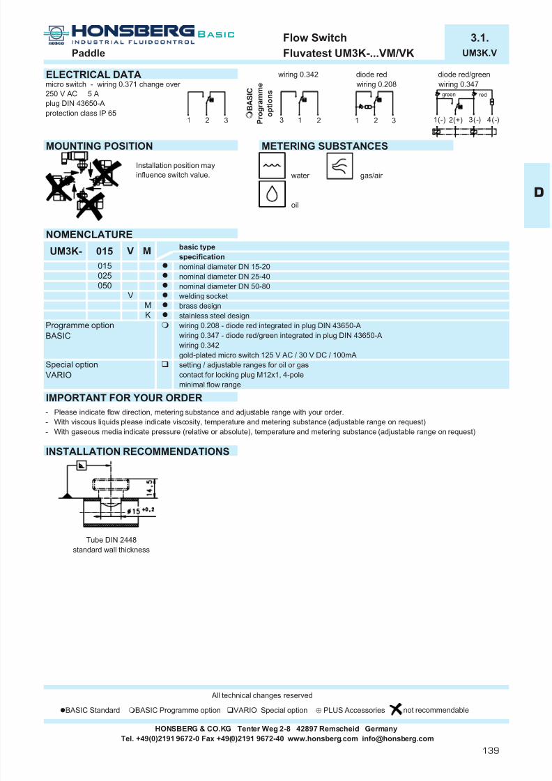
7/22/2019 General Honsberg
http://slidepdf.com/reader/full/general-honsberg 141/347
Flow Switch 3.1.Paddle Fluvatest UM3K-...VM/VK UM3K.V
ELECTRICAL DATA wiring 0.342 diode red diode red/greenmicro switch - wiring 0.371 change over wiring 0.208 wiring 0.347250 V AC 5 Aplug DIN 43650-Aprotection class IP 65
MOUNTING POSITION METERING SUBSTANCES
water gas/air
oil
NOMENCLATUREbasic typespecificationnominal diameter DN 15-20nominal diameter DN 25-40nominal diameter DN 50-80welding socketbrass designstainless steel designwiring 0.208 - diode red integrated in plug DIN 43650-Awiring 0.347 - diode red/green integrated in plug DIN 43650-Awiring 0.342gold-plated micro switch 125 V AC / 30 V DC / 100mAsetting / adjustable ranges for oil or gascontact for locking plug M12x1, 4-poleminimal flow range
IMPORTANT FOR YOUR ORDER- Please indicate flow direction, metering substance and adjustable range with your order.- With viscous liquids please indicate viscosity, temperature and metering substance (adjustable range on request)- With gaseous media indicate pressure (relative or absolute), temperature and metering substance (adjustable range on request)
INSTALLATION RECOMMENDATIONS
Tube DIN 2448standard wall thickness
All technical changes reserved
BASIC Standard BASIC Programme option VARIO Special option ⊕ PLUS Accessories not recommendable
HONSBERG & CO.KG Tenter Weg 2-8 42897 Remscheid GermanyTel. +49(0)2191 9672-0 Fax +49(0)2191 9672-40 www.honsberg.com [email protected]
BASICProgramme option
Special optionVARIO
Installation position mayinfluence switch value.
UM3K- 015 V M
050
015025
KM
V
B A S I C
P r o g r a m m e
o p t i o n s
1 2 3 3 1 2 1 32 1(-) 2(+) 3(-) 4(-)
green red
D
139
Basic
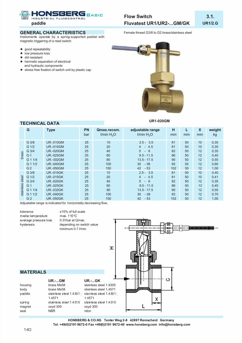
7/22/2019 General Honsberg
http://slidepdf.com/reader/full/general-honsberg 142/347
Flow Switch 3.1.paddle Fluvatest UR1/UR2-...GM/GK UR1/2.G
GENERAL CHARACTERISTICS Female thread G3/8 to G2 brass/stainless steel
TECHNICAL DATA
Adjustable range is indicated for horizontally decreasing flow.
tolerance ±15% of full scalemedia temperature max. 110°Caverage pressure loss 0.01bar at Qmax.hysteresis depending on switch value
minimum 0.7 l/min.
MATERIALS
UR.-...GM UR.-...GKhousing brass Ms58 stainless steel 1.4305body brass Ms58 stainless steel 1.4571paddle stainless steel 1.4301 ; stainless steel 1.4301 ;
1.4571 1.4571spring stainless steel 1.4310 stainless steel 1.4310magnet oxyd 300 oxyd 300seal NBR viton
HONSBERG & CO.KG Tenter Weg 2-8 42897 Remscheid GermanyTel. +49(0)2191 9672-0 Fax +49(0)2191 9672-40 www.honsberg.com [email protected]
G 2G 1 1/2
Type
UR.-015GMUR.-020GM
UR.-040GM
G
G 1 1/4 UR.-032GMUR.-025GM
4 - 4.55 - 69.5 - 11.5
13.5 - 17.530 - 3842 - 53 50
42 - 53
100
10
40
UR.-050GM
Xmm
10
102
90
Lmm
50505050
93
adjustable rangel/min H2O
weightkg
1,0012
0,350,35
1212
0,350,40
b r a s s
150
406080
G 1/2G 3/8
G 3/4
25G 1
25 20
2525
2525
0,60
8182
1250
860,55
1012
UR.-015GKUR.-020GK
2.5 - 3.520
UR.-010GK
5 - 6
UR.-032GK 80
25
UR.-050GK
4 - 4.50,35
G 1 UR.-025GK 25 9.5 - 11.5 1260 86
8182 50
12
12
1,00102 50 12
50 0,400,41
1050 10
81
G 2 25 s t a i n l e s s s t e e l
UR.-040GK
25
25
25G 3/4G 1/2G 3/8
150
0,5590 50 1213.5 - 17.5100 0,7030 - 38
Instruments operate by a spring-supported paddel withmagnetic triggering of a reed switch.
good repeatabilitylow pressure lossdirt resistanthermetic separation of electricaland hydraulic componentsstress free fixation of switch unit by plastic cap
93 50
81 50
PNbar
Qmax.recom.l/min H2O
Hmm
UR1-020GM
0,45G 1 1/4 25G 1 1/2
50
UR.-010GM 25 10 2.5 - 3.5
140
Basic

7/22/2019 General Honsberg
http://slidepdf.com/reader/full/general-honsberg 143/347
Flow Switch 3.1.paddle Fluvatest UR1/UR2-...GM/GK UR1/2.G
ELECTRICAL DATAreed switchwiring 0.225n.c. or n.o. depending on installation position230 V AC 1A 50VA1.5 m cable
protection class IP 65 type UR2 (plastic switching unit) without earthMOUNTING POSITION METERING SUBSTANCES
water gas/air
oil
NOMENCLATURE For combinations see table "technical data"
basic typespecificationswitch unit brassswitch unit and body plastic (PN10 - Tmax. 80°C - cable 0,5 m)DN 10 - G3/8DN 15 - G1/2DN 20 - G3/4DN 25 - G1DN 32 - G1 1/4DN 40 - G1 1/2DN 50 - G2female threadbrass designstainless steel design
setting / adjustable ranges for oil or gasspecial cable length
IMPORTANT FOR YOUR ORDER- Please indicate flow direction, metering substance and adjustable range with your order.- With viscous liquids please indicate viscosity, temperature and metering substance (adjustable range on request)- With gaseous media indicate pressure (relative or absolute), temperature and metering substance (adjustable range on request)
SPECIAL APPLICATIONS
UR2 plastic UI without magnet for liquid substanceswith fitting male thread plastic or brass G1/2A with ferrite contamination
or fitting female thread G3/8 - G2 with fitting male thread plastic or brass G1/2Aor fitting female thread G3/8 - G2
All technical changes reserved
BASIC Standard BASIC Programme option VARIO Special option ⊕ PLUS Accessories not recommendable
VARIO
HONSBERG & CO.KG Tenter Weg 2-8 42897 Remscheid GermanyTel. +49(0)2191 9672-0 Fax +49(0)2191 9672-40 www.honsberg.com [email protected]
Installation position mayinfluence switch value.
A
Special option
MK
G
040050
032
010
015010
UR1-
020025
G M
n o m i n a l d i a m e t e r
switch unit ATEX (product information 92.1.U1)
UR1-UR2-
brow n blue brow n blue
D
141
Basic

7/22/2019 General Honsberg
http://slidepdf.com/reader/full/general-honsberg 144/347
Flow Switch 3.1.paddle Fluvatest UR1/UR2-...VM/VK UR1/2.V
GENERAL CHARACTERISTICS Welding/soldering socket DN15 to DN 80 brass/stainless steel
TECHNICAL DATA
Adjustable range is indicated for horizontally decreasing flow.Calibrated in tube DIN2448 standard wall thickness.
tolerance ±15% of full scalemedia temperature max. 110°Caverage pressure loss 0.01bar at Qmax.hysteresis depending on switch value
minimum 0.7 l/min.
MATERIALS
UR.-...VM UR.-...VKsocket brass Ms58 stainless steel 1.4305body brass Ms58 stainless steel 1.4571paddle stainless steel 1.4301 ; stainless steel 1.4301 ;
1.4571 1.4571spring stainless steel 1.4310 stainless steel 1.4310magnet oxyd 300 oxyd 300seal NBR viton
HONSBERG & CO.KG Tenter Weg 2-8 42897 Remscheid GermanyTel. +49(0)2191 9672-0 Fax +49(0)2191 9672-40 www.honsberg.com [email protected]
UR1-015VM
40UR.-050VM
6550 12-
80100150
25
200
26 - 33
25
Amm
-
Dmm
13
- 12
Bmm
-
16
weightkg
0.2120
Qmax. recom.l/min H2O
32252015
40
DN
UR.-025VM
Type
25
PNbar
UR.-015VM
Hmm
16
19
18.0
1380
2020
600
25
- 0.219.1 - 124.6 - 6.3
UR.-025VK 25 80 - 1227.510 - 12.840
18.0147 - 179
95 - 117400
- 12150 33.7 - 41.2100 23.7 - 32
19 0.23
0.22
0.23
27.5 0.22
adjustable rangel/min H2O
5 - 6.510 - 15.511 - 13
134 - 174
37 - 42.547.5 - 60
-
42.0
400 86.5 - 113200
40
80
42.043.2 - 58.2
600
s t a i n l e s s s t e e l
UR.-015VK 25
65
32
15
Instruments operate by a spring-supported paddel withmagnetic triggering of a reed switch.
good repeatabilitylow pressure lossdirt resistanthermetic separation of electricaland hydraulic componentsstress free fixation of switch unit by plastic cap
b r a s s
50 UR.-050VK 25
142
Basic

7/22/2019 General Honsberg
http://slidepdf.com/reader/full/general-honsberg 145/347
Flow Switch 3.1.paddle Fluvatest UR1/UR2-...VM/VK UR1/2.V
ELECTRICAL DATAreed switchwiring 0.225n.c. or n.o. depending on installation position230 V AC 1A 50VA1.5 m cable
protection class IP 65 type UR2 (plastic switching unit) without earthMOUNTING POSITION METERING SUBSTANCES
water gas/air
oil
NOMENCLATUREbasic typespecificationswitch unit brassswitch unit and body plastic (PN10 - Tmax. 80°C - cable 0,5 m)nominal diameter DN 15-20nominal diameter DN 25-40nominal diameter DN 50-80welding socketbrass designstainless steel design
setting / adjustable ranges for oil or gasspecial cable length
IMPORTANT FOR YOUR ORDER- Please indicate flow direction, metering substance and adjustable range with your order.- With viscous liquids please indicate viscosity, temperature and metering substance (adjustable range on request)- With gaseous media indicate pressure (relative or absolute), temperature and metering substance (adjustable range on request)
INSTALLATION RECOMMENDATIONS SPECIAL APPLICATIONS
Tube DIN 2448standard wall thickness
UR1-015HMbody male thread G1/2A
UR1-032HMbody with union andmale thread G1/2A
All technical changes reserved
lBASIC Standard BASIC Programme option VARIO Special option ⊕ PLUS Accessories not recommendable
switch unit ATEX (product information 92.1.U1)
HONSBERG & CO.KG Tenter Weg 2-8 42897 Remscheid GermanyTel. +49(0)2191 9672-0 Fax +49(0)2191 9672-40 www.honsberg.com [email protected]
Installation position mayinfluence switch value.
A
Special option
K
VM
015025
015 V M
050
UR1-UR1-UR2-
VARIO
brow n blue brown blue
D
143
Basic

7/22/2019 General Honsberg
http://slidepdf.com/reader/full/general-honsberg 146/347
Flow Switch 3.1.paddle Fluvatest UB1 UB1.
GENERAL CHARACTERISTICS Male thread R1" brass/stainless steelSocket flange DN32 brass/stainless steel
TECHNICAL DATA
Adjustable range is indicated for horizontally decreasing flow.DN 25-32 only male thread design, DN 125-200 on request
media temperature max. 140°Cambient temperature -20..+70°Ctolerance ±15% of full scaleaverage pressure loss 0,08 bar at Qmax.hysteresis depending on switch value
minimum 0.1 m³/hweight 1.3 kg male thread design
2.5 kg socket flange design
WERKSTOFFE
UB1-….M UB1-….Khousing brass Ms58 s.s. 1.4305 Paddel 1 to adjusting for DN25 flange DIN 2527 nominalpaddle s.s. 1.4305/1.4310 s.s. 1.4305/1.4310 Paddel 4 may be adjusted to pipe size pressure 16 nominal diameter 32bellow s.s 1.4541 s.s. 1.4541 DN 100 paddle lenght 92 sealing surface DIN 2526 form Ccap PC PC DN 125 paddle lenght 117 Attention! Flange seal is notflange/socket Rg5/Ms s.s. 1.4305 DN 150 paddle lenght 143 included in standardseal NBR viton from DN 175 original paddle lenght shipment.
HONSBERG & CO.KG Tenter Weg 2-8 42897 Remscheid GermanyTel. +49(0)2191 9672-0 Fax +49(0)2191 9672-40 www.honsberg.com [email protected]
UB1-032EM
UB1-025HM
-100 16 75 21.6 - 34.0 12.8 - 20.1 8.4 - 13.9 7.0 - 12.4
45 16.0 - 24.9 8.7 - 14.1 4.4 - 8.09.5 - 16.7 4.7 - 8.3 - -
- - -1.9 - 3.4 - -
- - -
50 16 20 5.1 - 7.9
32 16 8- - -
Paddel 1,225 16 4 1.2 - 2.0
65
Qmax. recom.m³/h H2O
16 3080
40 16 12 2.3 - 3.8
adjustable rangem³/h H2O
DN PNbar
Paddel 1 Paddel 1,2,3 Paddel 1,2,3,4
1.4 - 2.5
Attention! Paddle fixation not secured.With critical conditions (i.e. vibration) pleaseprotect paddle screws.
16
Mechanichal Flow Switch for liquids or gaseous media. Abellow-supported paddle activates an adjustable microswitch.
operational range a diameter 25-200micro switch with "combination contact" goldcoating for small currents and silver coatingfor larger currentslow pressure lossvisual functions control by transparent cover
transparentcover
144
Basic
full visibilityof operation
contact setting

7/22/2019 General Honsberg
http://slidepdf.com/reader/full/general-honsberg 147/347
Flow Switch 3.1.paddle Fluvatest UB1 UB1.
ELECTRICAL DATAMicro switch with "combination contact" gold coating for small currents and silver coating for larger currentswiring 0.371 change over plug DIN 43650-Aprotection class IP 65
MOUNTING POSITION METERING SUBSTANCES
design stainless steelwater for aggressive liquids
oil
NOMENCLATUREbasic typespecificationmale thread DN25 - R1"socket flange DN32brass designstainless steel designTÜV-approval 0000021402contact for locking plug M12x1, 4-poleprotection class IP 67apaque cover
IMPORTANT FOR YOUR ORDER- Please indicate flow direction, metering substance and adjustable range with your order.- With viscous liquids please indicate viscosity, temperature and metering substance (adjustable range on request)
INSTALLATION RECOMMENDATIONS
Male thread design Socket flange design
DN40-65 DN80-200
tube DIN 2448 standard wall thickness tube DIN 2448 standard wall thickness
ACCESSORIES
The socket flanges as indicated in the installation recommendationsare available in the Honsberg accessory rangeSee product information 71.1 FL.
All technical changes reserved
BASIC Standard BASIC Programme option VARIO Special option ⊕ PLUS Accessories not recommendable
BASIC
UB1-
KM
025H M
Installation position mayinfluence switch value.
032E025H
HONSBERG & CO.KG Tenter Weg 2-8 42897 Remscheid GermanyTel. +49(0)2191 9672-0 Fax +49(0)2191 9672-40 www.honsberg.com [email protected]
6A
Programme option
250V AC/DC125V AC/DC24V DC
12V DC
A max. A max. A min.
4V1,5A min. 1mA6Aresistive induktive
2Amax.
6A
5A6A6A
2 31
D
145
Basic

7/22/2019 General Honsberg
http://slidepdf.com/reader/full/general-honsberg 148/347
Flow Switch 3.1.paddle Fluvatest CM2K-025HM/HK CM2K.
GENERAL CHARACTERISTICS Male thread R1" brass/stainless steel
TECHNICAL DATA
Adjustable range is indicated for horizontally decreasing flow.
tolerance ±15 % of full scalemedia temperature max. 110°Caverage pressure loss 0.15 bar at Qmax.hysteresis depending on switch value
minimum 5 l/min.weight 0.35kg
dirt protectionMATERIALS
CM2K-025HM CM2K-025HKhousing brass Ms58 stainless steel
nickel plated 1.4571paddle stainless steel stainless steel Paddel 1 to adjusted for DN25
1.4301 ;1.4571 1.4301 ; 1,4571 Paddel 4 may be adjusted to pipe sizebellow NBR NBR DN 100 paddle lenght 92protection POM POMspring stainless steel 1.4310 stainless steel 1.4310magnet oxyd 300 oxyd 300
HONSBERG & CO.KG Tenter Weg 2-8 42897 Remscheid GermanyTel. +49(0)2191 9672-0 Fax +49(0)2191 9672-40 www.honsberg.com [email protected]
CM2K-025HM
13.3 - 15.3 6.7 - 8.4 5.4 - 6.7
-16.5 - 18.9 7.6 - 8.9 2.7 - 3.5 -11.4 - 13.3 4.8 - 5.7 -6.5 - 7.5 1.9 - 2.4 - -
- -
-2.3 - 2.7 - - -0.9 - 1.0
50
adjustable rangem³/h H2O
paddle 1 paddle 1,2 paddle 1,2,3 paddle 1,2,3,4
-
- -
2.8 - 3.4
6580
100
The instruments are working according to the technologyof a spring and bellow supported paddle. Electricalcontact effected by a micro switch.
nominal diameter 25-100
hermetic separation of electricaland hydraulic componentsprotection of functional components fromliquid by rubber belloweasy adjustment of switch
915
Qmax. recom.m³/h H2O
DN
2532 2540
6025
Dynamic diaphram follows thepaddle movement w/o frictionand protects moving partsagainst contamintation.
26.3 - 30.325
Attention! Paddle fixationnot secured.With critical conditions(i.e. vibration) pleaseprotect paddle screws.
2436
PNbar
25 3.66
252525
146
Basic
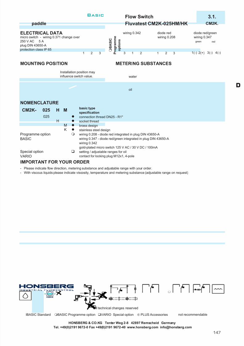
7/22/2019 General Honsberg
http://slidepdf.com/reader/full/general-honsberg 149/347
Flow Switch 3.1.paddle Fluvatest CM2K-025HM/HK CM2K.
ELECTRICAL DATA wiring 0.342 diode red diode red/greenmicro switch - wiring 0.371 change over wiring 0.208 wiring 0.347250 V AC 5 Aplug DIN 43650-Aprotection class IP 65
MOUNTING POSITION METERING SUBSTANCES
water
oil
NOMENCLATUREbasic typespecificationconnection thread DN25 - R1"
socket threadbrass designstainless steel designwiring 0.208 - diode red integrated in plug DIN 43650-Awiring 0.347 - diode red/green integrated in plug DIN 43650-Awiring 0.342gold-plated micro switch 125 V AC / 30 V DC / 100mAsetting / adjustable ranges for oilcontact for locking plug M12x1, 4-pole
IMPORTANT FOR YOUR ORDER- Please indicate flow direction, metering substance and adjustable range with your order.- With viscous liquids please indicate viscosity, temperature and metering substance (adjustable range on request)
All technical changes reserved
lBASIC Standard BASIC Programme option VARIO Special option ⊕ PLUS Accessories not recommendable
Installation position mayinfluence switch value.
BASIC
Special option
HONSBERG & CO.KG Tenter Weg 2-8 42897 Remscheid GermanyTel. +49(0)2191 9672-0 Fax +49(0)2191 9672-40 www.honsberg.com [email protected]
M025
M
CM2K-
K
H
H
B A S I C
P r o g r a m m e
o p t i o n s
025
VARIO
Programme option
1 2 3 3 1 2 1 32 1(-) 2(+) 3(-) 4(-)
green red
D
147
Basic

7/22/2019 General Honsberg
http://slidepdf.com/reader/full/general-honsberg 150/347
Flow Switch 3.1.paddle Fluvatest CRG-025HM/HK CRG.
GENERAL CHARACTERISTICS Male thread R1" brass/stainless steel
TECHNICAL DATA
Adjustable range is indicated for horizontally decreasing flow.
pressure CRG-025HM 11 bar static11 bar dynamic
CRG-025HK 30 bar static11 bar dynamic
media temperature max. 120°Caverage pressure loss 0.08bar at Qmax.hysteresis depending on switch value
minimum 0.1 l/min.weight CRG-025HM 0.90kg
CRG-025HK 0.95kg
MATERIALSPaddel 1 to adjusting for DN25
CRE-025HM CRE-025HK Paddel 4 may be adjusted to pipe sizehousing brass Ms58 stainless steel 1.4571 DN 100 paddle lenght 92paddle stainless steel 1.4571 stainless steel 1.4571 DN 125 paddle lenght 117bellow tombak stainless steel 1.4571 DN 150 paddle lenght 143cap ABS ABS from DN 175 original paddle lenght
HONSBERG & CO.KG Tenter Weg 2-8 42897 Remscheid GermanyTel. +49(0)2191 9672-0 Fax +49(0)2191 9672-40 www.honsberg.com [email protected]
Mechanichal Flow Switch for liquids or gaseous media. Abellow-supported paddle activates an adjustable microswitch. Rugged design in brass or stainless steel.
operational range a diameter 25-200good repeatabilitylow pressure loss
1,2,3
3.3 - 11.6
80
40 191,2
6.1 - 21.435.9 - 81.7
24
60
12060 6.1 - 17.3
12.3 - 30.6
1.2 - 4.9 1,21,2,3
Qmax. recom.m³/h H2O
paddle
11
36 2.1 - 7.44.3 - 10.72.7 - 6.5
1,2,3100
150
4.9 - 17.1
16.6 - 47.6
11.4 - 27.71,2,3,41,2,31,2,3,4120
1,2,3,4200
38.6 - 90.8 21.7 - 55.324025.7 - 90.1240
CRG-025HM
250.8 - 2.80.6 - 2.03.6
60.2 - 1.00.25- 1.432
adjustable rangereducedm³/h H2O
50 150.5 - 1.90.9 - 3.6
1.1 - 3.72.2 - 5.7
DN
Attention! Paddle fixation not secured.With critical conditions (i.e. vibration) pleaseprotect paddle screws.
65
adjustable rangem³/h H2O
72.6 - 165.7
148
Basic

7/22/2019 General Honsberg
http://slidepdf.com/reader/full/general-honsberg 151/347
Flow Switch 3.1.paddle Fluvatest CRG-025HM/HK CRG.
ELECTRICAL DATAmicro switch - wiring 0.374 change over 250 V AC 15(8) Acable gland Pg11protection class IP 65
MOUNTING POSITION METERING SUBSTANCES
design stainless steel CRG-025HKwater for aggressive liquids
oil
NOMENCLATUREbasic typespecificationconnection thread DN25 - R1"socket threadbrass designstainless steel designcable gland in capreduced adjustable rangegold contacts 125 V AC / 1 A
VARIO adjustment
IMPORTANT FOR YOUR ORDER- Please indicate flow direction, metering substance and adjustable range with your order.- With viscous liquids please indicate viscosity, temperature and metering substance (adjustable range on request)
INSTALLATION RECOMMENDATIONS SPECIAL APPLICATIONS
flow switch wind vane switchTÜV-approval
tube DIN 2448 standard wall thickness
Request please the data sheet Request please the data sheet3.1.CRE. 3.1.YR.
All technical changes reserved
lBASIC Standard BASIC Programme option VARIO Special option ⊕ PLUS Accessories not recommendable
HONSBERG & CO.KG Tenter Weg 2-8 42897 Remscheid GermanyTel. +49(0)2191 9672-0 Fax +49(0)2191 9672-40 www.honsberg.com [email protected]
Installation position mayinfluence switch value.
H MCRG- 025
Special option
S
MH
025
R
K
S
white red blue
D
149
Basic

7/22/2019 General Honsberg
http://slidepdf.com/reader/full/general-honsberg 152/347
Flow Switch 3.1.paddle Fluvatest VM-...EM/EK VM.E
GENERAL CHARACTERISTICS Socket flange DN40 to DN200 brass/stainless steel
TECHNICAL DATA
Adjustable range is indicated for horizontally decreasing flow.Calibrated in tube DIN2448 standard wall thickness, socket height 50mm.
tolerance ±5% of full scalemedia temperature max. 90°Caverage pressure loss 0.1bar at Qmax.hysteresis depending on switch value
minimum 5 l/min.
MATERIALS
VM-...EM VM-...EKflange bronze Rg5 stainless steel 1.4571body brass Ms58 stainless steel 1.4305
nickel platedpaddle stainless steel 1.4305 ; stainless steel 1.4305 ;
1.4301 1.4301components up to DN 80 -
stainless steel 1.4571from DN100 -brass Ms58
spring stainless steel stainless steel1.4310 1.4310 flange DIN 2527 nominal pressure 16 nominal diameter 32magnet oxyd 300 oxyd 300 sealing surface DIN 2526 form Cseal NBR viton Attention! Flange seal is not included in standard shipment.
HONSBERG & CO.KG Tenter Weg 2-8 42897 Remscheid GermanyTel. +49(0)2191 9672-0 Fax +49(0)2191 9672-40 www.honsberg.com [email protected]
Instruments operate with a spring-supported paddle andmagnetical triggering of an adjustable micro switch.
low pressure loss
high switch capabilityexact setting of switch via scale
Qmax. recom.l/min H2O
PNbar
TypeDN Lapprox
mm
weightkg
paddle-form
adjustable rangel/min H2O
250 - 750 158122198
300 - 900500 - 1500
125 - 375150 - 450200 - 600
90118115
3.53.5213
600 - 1800213198
3.03.03.03.0
65VM-050E.300
VM-065E.375
VM-150E.1500
100
45016
16
16VM-050E.150
VM-065E.300
16VM-080E.600
4050
1
2
1
12
550 1
1
3.0
10496
1153.03.0
3.03.03.0100 - 300
3.025050 - 150
100 - 300
93140 - 150
1450
14002700
16
VM-040E.150 16
VM-200E.3600
VM-150E.1800
16
900
55090016
161400
5400
80 VM-080E.450
150
VM-100E.750VM-100E.900
200 VM-200E.300016
1000 - 30001200 - 36005400
VM-050EM300
22 b
r a s s / s t a i n l e s s s t e e l
2216
162700
16
150
Basic

7/22/2019 General Honsberg
http://slidepdf.com/reader/full/general-honsberg 153/347
DN40-65 DN80-200 All technical changes reserved
BASIC Standard BASIC Programme option VARIO Special option ⊕ PLUS Accessories not recommendable
HONSBERG & CO.KG Tenter Weg 2-8 42897 Remscheid GermanyTel. +49(0)2191 9672-0 Fax +49(0)2191 9672-40 www.honsberg.com [email protected]
3000
a d j u s t a b l e
r a n g e
H 2
O h o r i z o n t a l
VARIO
Programme optionBASIC
E
Special option
900
600
1800
M
450375
K
200150100080065
E MVM- 040
Installation position mayinfluence switch value.
1500
300
3600
050040
150
750
150
n o m i n a l d i a m e t e r
o f p i p e
A switch head ATEX (product information 92.1.V2 + 92.1.V3)
1 2 3
Flow Switch 3.1.paddle Fluvatest VM-...EM/EK VM.E
ELECTRICAL DATAmicro switch - wiring 0.213 change over 250 V AC 6 Aplug DIN 43650-Aprotection class IP 44
MOUNTING POSITION METERING SUBSTANCES
water
oil
NOMENCLATURE For combinations see table "technical data"
basic typespecificationDN 40DN 50DN 65DN 80DN 100DN 150DN 200socket flangebrass designstainless steel design
40(50) - 150 l/min100 - 300 l/min125 - 375 l/min150 - 450 l/min200 - 600 l/min250 - 750 l/min300 - 900 l/min500 - 1500 l/min600 - 1800 l/min
1000 - 3000 l/min1200 - 3600 l/min
protection class IP 65nominal diameter DN 250-500gold-plated micro switchsignal lampspecial flangestemperature up to 250°C (stainless steel) / up to 200°C (brass) type VMX
IMPORTANT FOR YOUR ORDER- Please indicate flow direction, metering substance and adjustable range with your order.- With viscous liquids please indicate viscosity, temperature and metering substance (adjustable range on request)
INSTALLATION RECOMMENDATIONS ACCESSORIEStube Din 2448 The socket flanges as indicated in the installation recommendations
standard are available in the Honsberg accessory rangewall thickness See product information 71.1 FL.
D
151
Basic

7/22/2019 General Honsberg
http://slidepdf.com/reader/full/general-honsberg 154/347
Flowmeter 3.2.paddle Novatron TZ1-...EM/EK TZ1.E
GENERAL CHARACTERISTICS Socket flange DN40 to DN100 brass/stainless steel
TECHNICAL DATA
Metering range is indicated for horizontally increasing flow.Calibrated in tube DIN2448 standard wall thickness, socket height 50mm.
tolerance ±5% of full scalemedia temperature max. 90°Caverage pressure loss 0.1bar at Qmax.hysteresis depending on switch value
minimum 5 l/min.
MATERIALS
VM-...EM VM-...EKflange bronze Rg5 stainless steel 1.4571body brass Ms58 stainless steel 1.4305
nickel platedpaddle stainless steel 1.4305 ; stainless steel 1.4305 ;
1.4301 1.4301components up to DN 80 -
stainless steel 1.4571from DN100 -brass Ms58
spring stainless steel stainless steel1.4310 1.4310 flange DIN 2527 nominal pressure 16 nominal diameter 32magnet oxyd 300 oxyd 300 sealing surface DIN 2526 form Cseal NBR viton Attention! Flange seal is not included in standard shipment.
HONSBERG & CO.KG Tenter Weg 2-8 42897 Remscheid GermanyTel. +49(0)2191 9672-0 Fax +49(0)2191 9672-40 www.honsberg.com [email protected]
Mechanical Flowmeter for liquids or gaseous media. Withmechanical triggering of a metering unit with 270° of pointer range. Robust design, produced in materials brassor stainless steel.
local meteringlow pressure losseasy adjustment by indicating pointer
Lapprox
mm
weightkg
TZ1-050E.350
TZ1-065E.350
TZ1-100E.1050
DN Type PNbar
16900
TZ1-050EM300
216
16
40
1
100 - 450
200 - 600
350 - 1050300 - 800 2
112
333
333
14001400
158148
3
1261
98111101
1
13
16 100 - 350 1
350 - 250 1
1100 - 350 180 - 350
100 TZ1-100E.800
50
65TZ1-050E.450
TZ1-065E.500
16
900
16
80
16
16
b r a s s / s t a i n l e s s s t e e l
TZ1-040E.250
TZ1-080E.600TZ1-080E.450
316
TZ1-040E.350 16
550550 150 - 500
9387
450450
98
paddle-form
Qmax. recom.l/min H2O
450
130 - 450
metering rangel/min H2O
450
152
Basic

7/22/2019 General Honsberg
http://slidepdf.com/reader/full/general-honsberg 155/347
Flowmeter 3.2.paddle Novatron TZ1-...EM/EK TZ1.E
ELECTRICAL DATA
No electrical components. integrated micro switchwith front switch unitssee data sheet 1.3.TZ1.ZE
MOUNTING POSITION METERING SUBSTANCES
water
oil
NOMENCLATURE For combinations see table "technical data".
basic typespecificationFlowmeter Flowmeter with integrated micro switchDN 40DN 50DN 65DN 80DN 100socket flangebrass designstainless steel design
50 - 250 l/min(80) 100 - 350 l/min
(100) 130 - 450 l/min150 - 500 l/min200 - 600 l/min300 - 800 l/min350 - 1050 l/minfront switch unit with 10-kOhm-potentiometer
BASIC diodenominal diameter DN 125-500special rangesmetering range for oilfront switch unit 2pol, n.o. or n.c.
IMPORTANT FOR YOUR ORDER- Please indicate flow direction, metering substance and metering range with your order.- With viscous liquids please indicate viscosity, temperature and metering substance (metering range on request)- For additional information concerning options micro switch and front switch see data sheet 1.3.TZ1M.ZE.
INSTALLATION RECOMMENDATIONS ACCESSORIES
The socket flanges as indicated in the installation recommendationsare available in the Honsberg accessory rangeSee product information 71.1 FL.
DN40-65 DN80-200
All technical changes reserved
BASIC Standard BASIC Programme option VARIO Special option ⊕ PLUS Accessories not recommendable
100 n o m i n a l
d i a m e t e r o f
p i p e
M
tube Din 2448
BASIC Programme optionBASIC Standard
040
250TZ1- 040 E
050065
TZ1-
080
TZ1M-
250
450500600
350
8001050
E
K
Installation position mayinfluence metering range.
Programme option
Special option
m e t e r i n g r a n g e
H 2 O
h o r i z o n t a l
M
VARIO
standard wall thickness
HONSBERG & CO.KG Tenter Weg 2-8 42897 Remscheid GermanyTel. +49(0)2191 9672-0 Fax +49(0)2191 9672-40 www.honsberg.com [email protected]
D
153
Basic

7/22/2019 General Honsberg
http://slidepdf.com/reader/full/general-honsberg 156/347
Flowmeter 3.2.paddle Fluvatest UZ-...GM/GK UZ.G
GENERAL CHARACTERISTICS Female thread G1/2 to G2 brass/stainless steel
TECHNICAL DATA
Metering range is indicated for horizontally increasing flow.Please notice the pressure-dependend deviation of the indication range.
tolerance ±3% of full scalepressure range 16 bar static
6 bar dynamicmedia temperature max. 100°Caverage pressure loss 0.2 bar at Qmax.
MATERIALS
UZ-...GM UZ-...GKhousing brass Ms58 stainless steel 1.4305
nickel platedpaddle stainless steel 1.4571 ; stainless steel 1.4571 ;
1.4305 1.4305bellow stainless steel 1.4571 stainless steel 1.4571
HONSBERG & CO.KG Tenter Weg 2-8 42897 Remscheid GermanyTel. +49(0)2191 9672-0 Fax +49(0)2191 9672-40 www.honsberg.com [email protected]
Mechanichal Flowmeter for liquids. A bellow-supportedpaddle activates a metering unit with a pointer range of 270°. Rugged design in brass or stainless steel.
local meteringlow pressure lossgood repeatabilitydirt-resistanteasy adjustment by indicating pointer
UZ-025GM100
60
227100 - 500
UZ-020GK...
Hmm
200300400600
28
5587
400600
6570
111130
4.55.0
24
UZ-025GM...UZ-032GM...UZ-040GM...UZ-050GM...
303646
46209
Lmm
weightkg
2.02.02.5
206201
22
Type
UZ-015GM...UZ-020GM...
AFmm
3036
Qmax.recom.
l/min H2O
60100
201
3.04.55.0
2.02.02.53.0
707487
104
201201209
130227
7470UZ-015GK...
G 2
b r a s s
G 1/2
G 1G 3/4
G 3/4
G 1 1/2G 1 1/4
200
s t a i n l e s s s t e e l
G 1/2 100 4 - 60 4 - 453 - 50G 1 UZ-025GK...
G 2
300
556570
20 - 200 10 - 30030 - 500
10 - 100
20 - 3002428
20 - 20060 - 300
215 11110 - 300100 - 500
6 - 7010 - 10020 - 20020 - 200 10 - 100
4 - 604 - 60
19
G
2 - 35left
metering rangel/min H2O ; 1bar abs
flow fromright (optional)
3 - 50
1910 - 100
Xmm
2 - 35 18
1618
4 - 504 - 45
166 - 70 206
22G 1 1/2 UZ-040GK... 215
UZ-032GK...G 1 1/4 10 - 100 20 - 200 10 - 100 10410 - 300
4 - 60 10 - 10020 - 200
20 - 200 10 - 300 20 - 200
4 - 50 10 - 100
20 - 300 30 - 500 60 - 300UZ-050GK...
0 2 4 6 8 bar 10
100
80
60
40
Q(%)
154
Basic

7/22/2019 General Honsberg
http://slidepdf.com/reader/full/general-honsberg 157/347
Flowmeter 3.2.paddle Fluvatest UZ-...GM/GK UZ.G
ELECTRICAL DATA
No electrical components. integrated micro switchwith front switch unitssee next page.
MOUNTING POSITION METERING SUBSTANCES
water
oil
NOMENCLATURE For combinations see table "technical data".
basic typespecificationFlowmeter Flowmeter with integrated micro switchDN 15 - G1/2DN 20 - G3/4DN 25 - G1DN 32 - G1 1/4DN 40 - G1 1/2DN 50 - G2socket flangebrass designstainless steel design
35 l/min of full scale45 l/min of full scale50 l/min of full scale60 l/min of full scale70 l/min of full scale
100 l/min of full scale200 l/min of full scale300 l/min of full scale500 l/min of full scalefront switch unit with 10-kOhm-potentiometer
BASICmetering range for oil or gasfront switch unit 2pol, n.o. or n.c.flange design
IMPORTANT FOR YOUR ORDER- Please indicate flow direction, metering substance and metering range with your order
With pressure >1 bars abs please require metering range.- With viscous liquids please indicate viscosity, temperature and metering substanc, e.g. ISO VG 68 (metering range on request)
All technical changes reserved
BASIC Standard BASIC Programme option VARIO Special option ⊕ PLUS Accessories not recommendable
HONSBERG & CO.KG Tenter Weg 2-8 42897 Remscheid GermanyTel. +49(0)2191 9672-0 Fax +49(0)2191 9672-40 www.honsberg.com [email protected]
m e t e r i n g r a n g e
H 2
O h o r i z o n t a l
VARIO
500Programme option
Installation position mayinfluence metering range.
BASIC Standard BASIC Programme option
060
200300
035
100
040032
050G
045
KM
050
UZ- 015
025
015UZM-UZ-
020
G M 035
Special option
070
n o m i n a l
d i a m e t e r
D
155
Basic
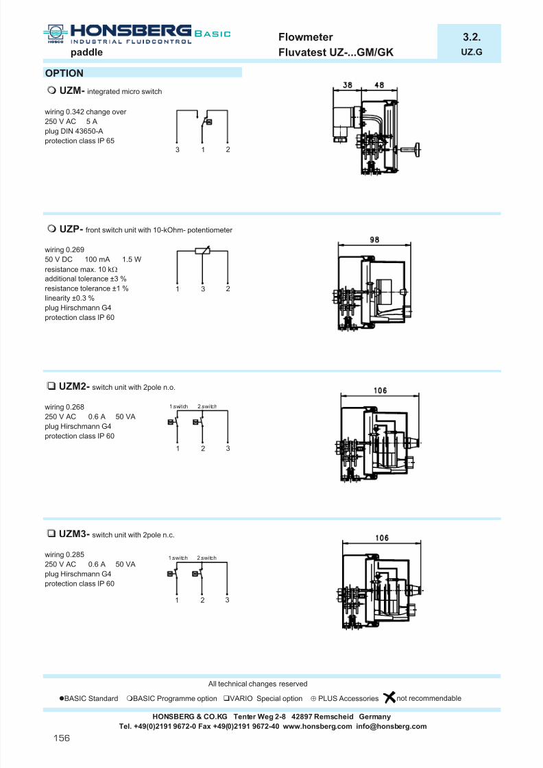
7/22/2019 General Honsberg
http://slidepdf.com/reader/full/general-honsberg 158/347
Flowmeter 3.2.paddle Fluvatest UZ-...GM/GK UZ.G
OPTION
wiring 0.342 change over 250 V AC 5 A
plug DIN 43650-Aprotection class IP 65
wiring 0.26950 V DC 100 mA 1.5 W
resistance max. 10 k Ω
additional tolerance ±3 %resistance tolerance ±1 %linearity ±0.3 %plug Hirschmann G4protection class IP 60
wiring 0.268250 V AC 0.6 A 50 VAplug Hirschmann G4protection class IP 60
wiring 0.285250 V AC 0.6 A 50 VAplug Hirschmann G4protection class IP 60
All technical changes reserved
BASIC Standard BASIC Programme option VARIO Special option ⊕ PLUS Accessories not recommendable
HONSBERG & CO.KG Tenter Weg 2-8 42897 Remscheid Germany
UZP- front switch unit with 10-kOhm- potentiometer
UZM2- switch unit with 2pole n.o.
UZM3- switch unit with 2pole n.c.
Tel. +49(0)2191 9672-0 Fax +49(0)2191 9672-40 www.honsberg.com [email protected]
UZM- integrated micro switch
1 2 3
1.switch 2.switch
1 2 3
1.switch 2.switch
1 3 2
3 1 2
156
Basic

7/22/2019 General Honsberg
http://slidepdf.com/reader/full/general-honsberg 159/347
flow switch / flowmeter 3.5.dynamic flap Flexoflow XF XF.1
GENERAL CHARACTERISTICS Female thread G1/4 to G3/4 brass
XF-020GMI080STECHNICAL DATA
tolerance 3% of measured valueminimum 0.25 l/min
media temperature 0..70°Caverage pressure loss 0.5 bar at top of range
OPERATION
MATERIAL
housing PPSconnection brass nickel plated
flap s.s. 1.4031kflap fastener PVDFindicator cobalt samariumsealing viton
HONSBERG & CO.KG Tenter Weg 2-8 42897 Remscheid GermanyTel. +49(0)2191 9672-0 Fax +49(0)2191 9672-40 www.honsberg.com [email protected]
A thin, spring-mounted shutter that covers the entire flowcross-section is displaced by the flow of the liquid. Theshutter has a magnet that creates a changing magneticfield when the shutter is displaced. This field is detectedby a analogue hall-sensor. Due to the spring properties of the shutter and a molded stop, even strong water impactscan be withstood. The low number of parts coming intocontact with media guarantees low soiling properties andreliable operation.
fast response timelarge overload securitymeasurement range 1:80!low pressure losscompact dimension
It has to be observed, that the sensor is installed in the direction of the flowarrow. Despite its low mass, the shutter is very robust. In case of disassembly or mounting, however, it still should not be forcibly bent or compressed.The housing screws go through the entire housing and have to be removedcompletely when the sensor head is exchanged. After that, the body, asusual in the case of a flange part, can be removed without loosening thescrew connection. If return flows occur, please ask about alternatives!
The extremely bendableshutter is flush with a stop andcan thus never beoverstretched by water impacts.
Since the shutter functions only through bending without a rotary bearing,there are no friction effects and thus a very small hysteresis and goodreproducibility of the measurement results or switching point. The low mass
and evaluation of the entire flow cross-section are responsible for the fastresponse time and unproblematic pipeline routing.
G Type
G 1/2 XF-015GM.
weightkgmm
PNbar mm
G 1/4 XF-008GM. 16 1 - 15 l/min 74 12
rangel/min H2O
L X
78 14
0.60G 3/8 XF-010GM. 16 1 - 25 l/min 74 12 0.60
0.60G 3/4 XF-020GM. 16 1 - 80 l/min 82 16 0.65
16 1 - 50 l/min
Flow
D
157
Basic

7/22/2019 General Honsberg
http://slidepdf.com/reader/full/general-honsberg 160/347
flow switch / flowmeter 3.5.dynamic flap Flexoflow XF XF.1
ELECTRICAL DAT
supply voltage 10..30 V DC idle current 100 mAconnection for locking plug M12x1, 4-pole output current 4..20 mAshort-circuit proof yes voltage 0..10Vreverse polarity proof yes frequency output / programmable switch
protection class IP 67 idle current < 20 mA (without load)output push-pull (PNP and NPN)10..2000 Hz
MOUNTING POSITION METERING SUBSTANCES
water
NOMENCLATURE For combinations see table "technical data".
basic typespecificationnominal diameter DN 8nominal diameter DN 10nominal diameter DN 15nominal diameter DN 20female threadmale threadconnection material brassconnection material stainless steelconnection material POMvoltage output 0..10Vcurrent output 4..20mAfrequency outputprogrammable switch (push-pull = PNP and NPN)output at suburb electronics (e.g. omni-XF)reed switch change over (on request)proximity switch PNP n.o. (on request)proximity switch NPN n.o. (on request)range 1 - 15 l/minrange 1 - 25 l/minrange 1 - 50 l/minrange 1 - 80 l/minconnection at locking plugs M12x1, 4-pole
COMBINATIONS
omni-XF Flex-XFlocal electronic unit, switching and frequency output2x push-pull-switch 0..10V or 4..20mA4(0)..20mA output pnp, npngraphical LCD display with flashing LEDprogram ring
All technical changes reserved
BASIC Standard BASIC Programme option VARIO Special option ⊕ PLUS Accessories not recommendable
050025015
current - / voltage output
S
XF- 008 G M
015010
U
020
K
S
FI
The sensor can be operated in any position. The shutter has the lowest tendency towards soiling, however, when itswings from the bottom to the top. The installation positioninfluences the adjusting range!
R 015008
G A
M
P
PR
N
E
080
HONSBERG & CO.KG Tenter Weg 2-8 42897 Remscheid GermanyTel. +49(0)2191 9672-0 Fax +49(0)2191 9672-40 www.honsberg.com [email protected]
S
PNP / current- / voltage output
1
4
3
black
blue zoutput
0 V
+brow n
2 programmingw hite
NPN
1
4
3
black
blue
zoutput
0 V
+brow n
2 programmingw hite
158
Basic

7/22/2019 General Honsberg
http://slidepdf.com/reader/full/general-honsberg 161/347
l Magnetic triggering of a fully Õ high switch perfor-separated micro switch mance, no relais
l Stainless steel paddle and Õ versatility in installationspring support and liquid selection
l Magnetic link Õ without mechanicalinterference
l optional fitting or cap nut Õ for direct pipeinstallation
Why to use a paddle instrument
159
Basic

7/22/2019 General Honsberg
http://slidepdf.com/reader/full/general-honsberg 162/347
Market segments
Application
l Boilers
l Transformers
l Swimming pools
l Pumps
l Burners
l Engine
l High transportationspeed
l Command of the diverter valve in combi boilersl Alarm in transformers in case of missing oil lubricationl Control of chemical additives in commercial poolsl Shut off burners in case of water failure
Where to use a paddle instrument
Honsberg & Co. KGTenter Weg 2-8 · 42897 Remscheid · GermanyP.O. Box 1103 69 · 42863 Remscheid · GermanyTel. +49(0)2191 9672-0 · Fax +49(0)2191 9672-40www.honsberg.com · [email protected]
160
Basic
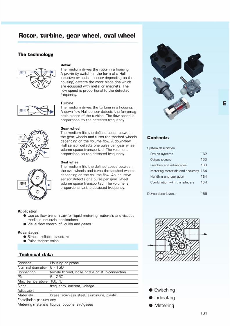
7/22/2019 General Honsberg
http://slidepdf.com/reader/full/general-honsberg 163/347
161
Rotor, turbine, gear wheel, oval wheel
RotorThe medium drives the rotor in a housing.A proximity switch (in the form of a Hall,inductive or optical sensor depending on thehousing) detects the rotor blade tips whichare equipped with metal or magnets. Theflow speed is proportional to the detectedfrequency.
TurbineThe medium drives the turbine in a housing.A down-flow Hall sensor detects the ferromag-netic blades of the turbine. The flow speed isproportional to the detected frequency.
Gear wheelThe medium fills the defined space between
the gear wheels and turns the toothed wheelsdepending on the volume flow. A down-flowHall sensor detects one pulse per gear wheel
volume space transported. The volume isproportional to the detected frequency.
Oval wheelThe medium fills the defined space between
the oval wheels and turns the toothed wheelsdepending on the volume flow. An inductivesensor detects one pulse per gear wheel
volume space transported. The volume isproportional to the detected frequency.
Concept Housing or probeNominal diameter 6 - 150Connection female thread, hose nozzle or stub-connectionPN 6 - 250Max. temperature 100 °CSignal frequency, current, voltageAdjustable –Materials brass, stainless steel, aluminium, plasticEnstallation position anyMetering materials liquids, optional air/gases
Technical data
l Switchingl Indicatingl Metering
Contents
System description
Device systems 162
Output signals 163
Function and advantages 163
Metering materials and accuracy 164Handling and operation 164
Combination with transducers 164
Device descriptions 165
The technology
Applicationl Use as flow transmitter for liquid metering materials and viscous
media in industrial applicationsl Visual flow control of liquids and gases
Advantagesl Simple, reliable structurel Pulse transmission
E

7/22/2019 General Honsberg
http://slidepdf.com/reader/full/general-honsberg 164/347
Honsberg & Co. KGTenter Weg 2-8 · 42897 Remscheid · GermanyP.O. Box 1103 69 · 42863 Remscheid · GermanyTel. +49(0)2191 9672-0 · Fax +49(0)2191 9672-40www.honsberg.com · [email protected]
Basic
162
System description
Device systemsThe Honsberg device systems rotor, turbine, gear wheel and oval wheelare used for flow indication and continuous flow metering. The primarycomponent is the rotor or turbine, gear wheel or oval wheel situatedin the liquid chamber. What these primary elements have in common is
that the medium which enters the space causes the element to revolvedirectly proportionally to the flow rate, thus allowing visual indication of
the flow rate via the revolution or producing a linear output signaldependent on the flow by activating sensors.
Appropriately integrated circuits used in place of basic sensors producefrequency modulating signals, switching signals or 4..20 mA outputs.
RotorThe rotor is a rotary element positioned frontally arranged with positivelocking on a bearing-supported axis. It is set in rotary motion by theflow.
TurbineThe turbine is a rotary element with linear blade orientation to flowdirection and rotate proportionally to the flow around an axis positioned
in flow direction.
Gear wheelA metal pair of gear wheels rotates around a metal axis in a metalhousing. Viscosity stability is given thanks due to volumetric operation.
Oval wheelA plastic pair of oval wheels rotates around a metal axis. Viscositystability is given due to volumetric operation.
Rotor Turbine Gear wheel Oval wheel
Accuracy± 3% ± 1% ± 3% ± 2.5%
Measured value Final value Measured value Final valueLiquids + + + +Gases optional optional - -
Viscosity up to up to+ +
compensated 10 mm 2 / s 15 mm 2 / sRanges l/min 0.1-1000 0.1-1130 0.02-1501 0.3-40Max. Temperature °C 100 90 120 60
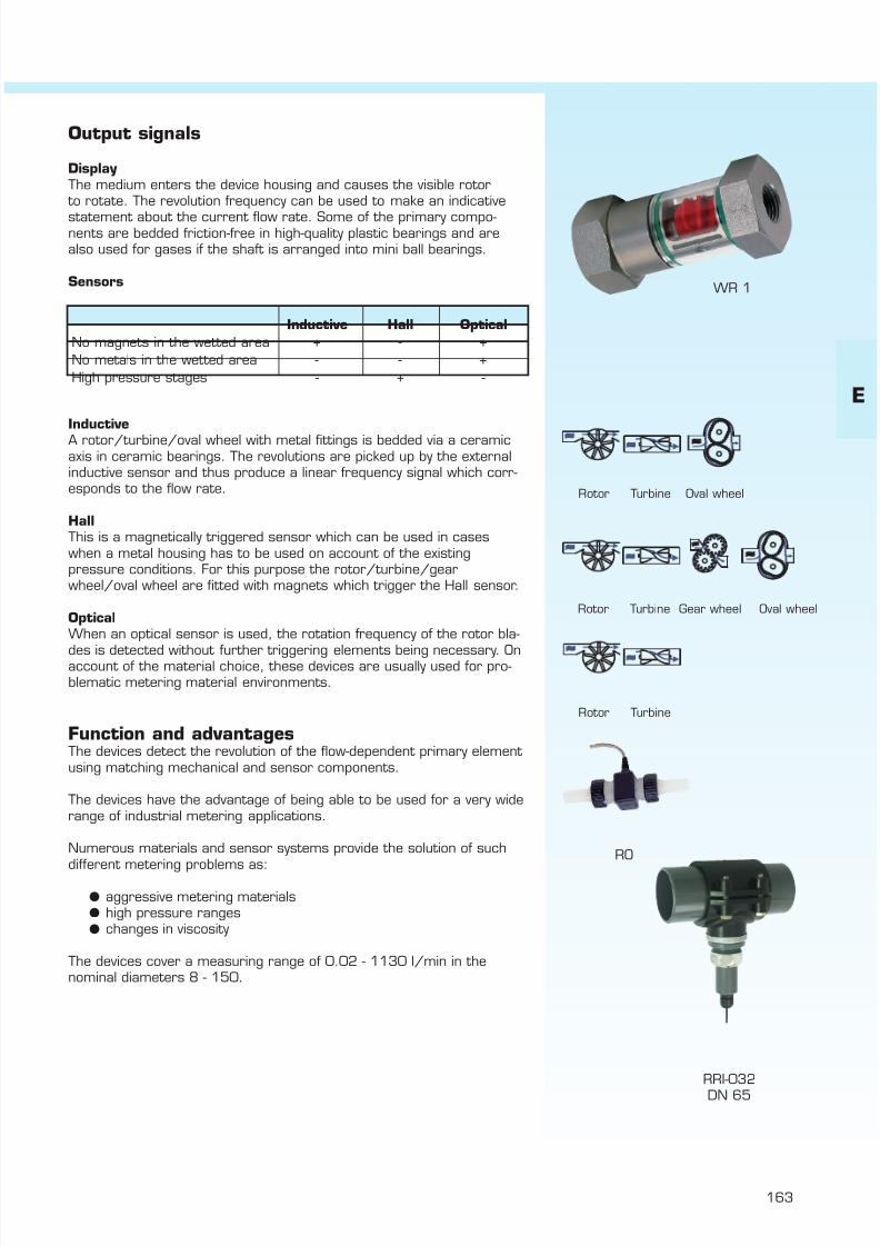
7/22/2019 General Honsberg
http://slidepdf.com/reader/full/general-honsberg 165/347
163
Output signals
Display The medium enters the device housing and causes the visible rotor
to rotate. The revolution frequency can be used to make an indicative
statement about the current flow rate. Some of the primary compo-nents are bedded friction-free in high-quality plastic bearings and arealso used for gases if the shaft is arranged into mini ball bearings.
Sensors
InductiveA rotor/turbine/oval wheel with metal fittings is bedded via a ceramicaxis in ceramic bearings. The revolutions are picked up by the externalinductive sensor and thus produce a linear frequency signal which corr-esponds to the flow rate.
HallThis is a magnetically triggered sensor which can be used in caseswhen a metal housing has to be used on account of the existingpressure conditions. For this purpose the rotor/turbine/gearwheel/oval wheel are fitted with magnets which trigger the Hall sensor.
OpticalWhen an optical sensor is used, the rotation frequency of the rotor bla-
des is detected without further triggering elements being necessary. Onaccount of the material choice, these devices are usually used for pro-blematic metering material environments.
Function and advantagesThe devices detect the revolution of the flow-dependent primary element using matching mechanical and sensor components.
The devices have the advantage of being able to be used for a very widerange of industrial metering applications.
Numerous materials and sensor systems provide the solution of suchdifferent metering problems as:
l aggressive metering materialsl high pressure rangesl changes in viscosity
The devices cover a measuring range of 0.02 - 1130 l/min in thenominal diameters 8 - 150.
Inductive Hall OpticalNo magnets in the wetted area + - +No metals in the wetted area - - +High pressure stages - + -
WR 1
RRI-032DN 65
RO
Rotor Turbine Oval wheel
Rotor Turbine Gear wheel Oval wheel
Rotor Turbine
E

7/22/2019 General Honsberg
http://slidepdf.com/reader/full/general-honsberg 166/347
Honsberg & Co. KGTenter Weg 2-8 · 42897 Remscheid · GermanyP.O. Box 1103 69 · 42863 Remscheid · GermanyTel. +49(0)2191 9672-0 · Fax +49(0)2191 9672-40www.honsberg.com · [email protected]
Basic
164
Metering materials and accuraciesThe products described are primarily used with liquids. Volumetricsystems such as gear wheel or oval wheel should be chosen for viscousmetering materials from 10 mm²/s.
Gear wheel / oval wheel = volumetric systemThe liquid volume per tooth does not depend on viscosity, making themetering result independent of viscosity.
Example:
Volume Viscosity Flow rate30 cm 3 1 mm 2 /s 5.0 l/min30 cm 3 115 mm 2 /s 5.0 l/min
no deviation
Accuracies are in the range of 1-3 % depending on the specific versionused.
Handling and operationFor rotors and turbines, the inner diameter of the connection pipealways has to be greater than the inlet port of the flow meter. It ismandatory that the flow meter is always filled with medium, andremains filled. Any installation position is possible, but the positionwhich allows the best possible venting should be chosen [flow horizontalor from bottom to top]. Note! Air bubbles have a great influence onmetering results, as with any flow meter!
Always keep the rotor under medium
Combination with transducers
VHZ group
E x t e r n a
l
t r a n s
d u c e r s
H e a
d s
P r i m a r y s e n s o r s

7/22/2019 General Honsberg
http://slidepdf.com/reader/full/general-honsberg 167/347
165
E
m i s c e
l l a n e o u s
p a g e
a g g r e s s
i v e
g a s
/ a
i r
o i l
i n d i c a t i o n
t y p e
c o n t r o
l
c o n n e c t i o n
o u t p u t s i g n a
l
o n s
i t e m e t e r i n g
m a x . p r e s s u r e
b a r
m a x . t e m p e r a t u r e
° C
w a t e r
n o m
i n a
l d i a m e t e r
l standard m standard option special option all data sheets available under www.honsberg.com
PO 10 - 25 female thread plastic l 16 60 l 3 166
FR 15 - 25 female thread bronze l 16 100 l 3 167
RM 8 - 25 female thread bronze l 16 100 l 3 168
WR1 8 - 40 female thread brass l 16 100 l 3 169female thread stainless steel l 16 100 l 3
RA 8 male thread POM l 10 55 l 3 170male thread HALAR l 10 55 l 3
RH 8 male thread POM l 10 80 l 3 172nozzle Æ 8 POM l 5 80 l 3
RRI 10 - 25 female thread plastic m m l m 16 60 l 3 174
RRH 10 - 25 female thread brass m m l m 100 100 l 3 176female thread stainless steel m m l m 100 100 l 3
RRO 10 - 25 female thread plastic m m l m 16 60 l 3 3 178
RR.-32 32 - 150 pipe PVC m l 10 60 l 3 18050- 150 assembly clamp saddle PP m l 10 60 l 3
assembly screwed-in probe m l 10 60 l 3
welded socket VA m l 100 100 l 3 3
HV 8 - 25 female thread brass l 10 100 l 3 183
RO 5 - 15 nozzle plastic l 6 85 l 3 filter 184
RRF 10 female thread plastic l 14 100 l 3 185
RRT 20 female thread plastic m l m 10 90 l 3 187female thread brass m l m 100 90 l 3
RRT1 10 female thread plastic m l m 10 90 l 3 flow regulator, 188female thread brass m l m 100 90 l 3 filter check,
valve
RT 15 - 50 male thread stainless steel m l m 250 85 l 3 3 190
VHZ 8 female thread Al/stainless steel m l m 200 85 l l 19210 female thread Al/stainless steel m l m 200 85 l l
20 female thread Al/stainless steel m m l m 200 85 l l
25 female thread Al/stainless steel m l m 100 85 l l
VHO 15 - 20 female thread plastic m l l m 10 60 l l 196
o v a
l w
h e e l g e a r w
h e e l
t u r b
i n e
r o t o r
HONSBERG & CO.KG Tenter Weg 2-8 42897 Remscheid GermanyTel. +49(0)2191 9672-0 Fax +49(0)2191 9672-40 www.honsberg.com [email protected]

7/22/2019 General Honsberg
http://slidepdf.com/reader/full/general-honsberg 168/347
Flow Indicator 4.1.rotor Visoflow PO-...GVA PO.
GENERAL CHARACTERISTICS Female thread G3/8 to G1 POM
PO-010GVATECHNICAL DATA
media temperature max. 60°C
MATERIALS
DN 10 DN 25body PPS (Fortron 1140L4) Questracover PSU Ultrason PC transparentrotor PVDF PVDFaxle ceramic ceramicbearings iglidur X iglidur Xseal viton viton
MOUNTING POSITION NOMENCLATUREbasic typespecificationnominal diameter DN 10 - G3/8nominal diameter DN 25 - G1female threadconnection material PVDFconnection material brass
housing materialQuestra / PPS withtransparent cover
METERING SUBSTANCES flow diameter Ø 2flow diameter Ø 5flow diameter Ø 7
Wasser flow diameter Ø 8flow diameter Ø12flow diameter Ø16
Öl
All technical changes reserved
BASIC Standard BASIC Programme option VARIO Special option ⊕ PLUS Accessories not recommendable
1838
22 12
27,5
Xmm
50 12,5 16,5
1210
G 1G 1
3060
G 1
Lmm
L1mm
Bmm
100
rangel/min H2O
0,1 - 1,50,2 - 100,4 - 122 - 303 - 60
1.5 50 84 29
7070
PO-025GVA160
16161616
PO-010GVA070PO-025GVA080PO-025GVA120
PO-
020
120160
070050
VM
G
G
Mechanical Flow Indicator for liquids with twin rotors for quantitative flow indication. The rotor provides a directlyflow-proportional indication of the actual flow rate.
optional installation
Q u e s t r a
025
G 3/80.423110 53
010
4 - 100
A 020V
G
G 3/8G 3/8
weightkg
0.1
Cmm
Hmm
Emm
SWmm
Qmax. rec .l/min H2O
080
Type PNbar
1616PO-010GVA050
PO-010GVA020
010
HONSBERG & CO.KG Tenter Weg 2-8 42897 Remscheid GermanyTel. +49(0)2191 9672-0 Fax +49(0)2191 9672-40 www.honsberg.com [email protected]
A
With higher viscosityinstruments tend to higher starting values for rotor.
Basic
166

7/22/2019 General Honsberg
http://slidepdf.com/reader/full/general-honsberg 169/347
Flow Indicator 4.1.rotor Visoflow FR-...GR FR.
GENERAL CHARACTERISTICS Female thread G1/2 to G1 bronze
FR-015GRTECHNICAL DATA
media temperature max. 100°Caverage pressue loss 0.09 bar at Qmax.
MATERIALS
body bronze Rg5ring brass Ms58window soda-lime natural glassbolt stainless steel 1.4305
rotor POMseal klingersil C4400
MOUNTING POSITION NOMENCLATUREbasic typespecificationnominal diameter DN 15 - G1/2nominal diameter DN 20 - G3/4nominal diameter DN 25 - G1female threadbronze
SPECIAL DESIGNS
METERING SUBSTANCES type RS-...GRfemale thread G1/4 bis G2rotor brass
water housing bronze
type RS-...FGoil flange DN 25 to 80
rotor brasshousing cast iron RS-040FG
All technical changes reserved
lBASIC Standard BASIC Programme option VARIO Special option ⊕ PLUS Accessories not recommendable
With higher viscosity instruments tend tohigher starting values for rotor.
Mechanical Flow Indicator for liquids with twin rotors for quantitative flow indication. The rotor provides a directlyflow-proportional indication of the actual flow rate. Ruggeddesign in bronze/brass combination.
double-faced windows for comfortable readingoptional installation
65
25
Type
FR-015GR 2.5
b r o n z e
G 3/436
Lmm
85
AFmm
68G 1/2
G 11616
FR-020GRFR-025GR
14
015
3.0
FR-
85
R
1.20
G PNbar
weightkg
16
Bmm
Xmm
start of rotor l/min H2O
Qmax. recom.l/min H2O
14
1.25955.01.1068 36
74 164245
020025
G
G015
R
HONSBERG & CO.KG Tenter Weg 2-8 42897 Remscheid GermanyTel. +49(0)2191 9672-0 Fax +49(0)2191 9672-40 www.honsberg.com [email protected]
E
Basic
167

7/22/2019 General Honsberg
http://slidepdf.com/reader/full/general-honsberg 170/347
Flow Indicator 4.1.rotor Visoflow RM-...GR RM.
GENERAL CHARACTERISTICS Female thread G1/4 to G1 bronze / steinless steel
RM-015GKTECHNICAL DATA
media temperature max. 100°C
MATERIALS
RM-…GR RM-…GKbody bronze stainless steelring brass stainless steel
dome borosilikate borosilikateshaft stainless steel stainless steelrotor PPS PPSseal Klingersil C-4400 Klingersil C-4400
MOUNTING POSITION NOMENCLATUREbasic typespecificationDN 8 - G1/4DN 10 - G3/8DN 15 - G1/2DN 20 - G3/4DN 25 - G1female threadbronzestainless steel
METERING SUBSTANCES
water
oil
All technical changes reserved
lBASIC Standard BASIC Programme option VARIO Special option ⊕ PLUS Accessories not recommendable
Tel. +49(0)2191 9672-0 Fax +49(0)2191 9672-40 www.honsberg.com [email protected]
1.200.25 89
HONSBERG & CO.KG Tenter Weg 2-8 42897 Remscheid Germany
89 66 45 1866 45
16 0.6514 0.6518 1.25
0.40 76 53 280.15 76 53 28
Xmm
weightkg
0.20 76 53 28 12 0.70
pressure lossat Qmax.
Lmm
Hmm
SWmm
60 1.540 1.2
10 0.820 1.0
Qmax. recom.l/min H2O
start of rotor l/min H2O
8 0.7
010015
G
G 1/4
PNbar
16
Type
RM-008G.
G 3/4G 1
RM-020G.RM-025G. 0.70
025
1616
16
020
008008
R
16
Mechanical Flow Indicator for liquids for quantitative flowindication. The rotor, which is arranged in a dome for goodvisibility, provides a directly flow- proportional indication of the actual flow rate. Rugged design in bronze/brass or stainless steel.
good rotor sighthigh temperature dutydome-shaped
With higher viscosityinstruments tend to higher starting values for rotor.
b r o n z e / s
. s .
RM-
RM-010G.RM-015G.
G 3/8G 1/2
G
K
n o m i n a l
d i a m e t e r
RG
Basic
168
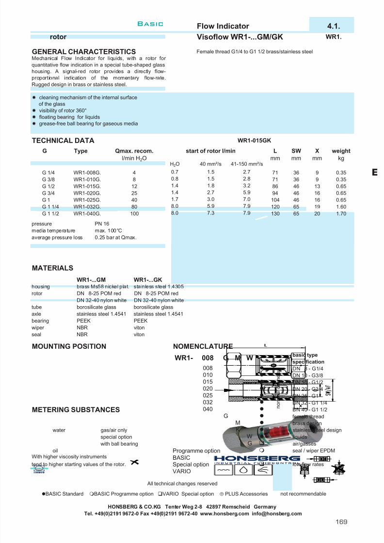
7/22/2019 General Honsberg
http://slidepdf.com/reader/full/general-honsberg 171/347
Flow Indicator 4.1.rotor Visoflow WR1-...GM/GK WR1.
GENERAL CHARACTERISTICS Female thread G1/4 to G1 1/2 brass/stainless steel
TECHNICAL DATA WR1-015GK
pressure PN 16media temperature max. 100°Caverage pressure loss 0.25 bar at Qmax.
MATERIALS
WR1-...GM WR1-...GKhousing brass Ms58 nickel plat. stainless steel 1.4305rotor DN 8-25 POM red DN 8-25 POM red
DN 32-40 nylon white DN 32-40 nylon whitetube borosilicate glass borosilicate glassaxle stainless steel 1.4541 stainless steel 1.4541bearing PEEK PEEKwiper NBR vitonseal NBR viton
MOUNTING POSITION NOMENCLATUREbasic typespecificationDN 8 - G1/4DN 10 - G3/8DN 15 - G1/2DN 20 - G3/4DN 25 - G1DN 32 - G1 1/4
METERING SUBSTANCES DN 40 - G1 1/2female threadbrass design
water gas/air only stainless steel designspecial option liquidswith ball bearing air/gasses
oil Programme option seal / wiper EPDMWith higher viscosity instruments BASICtend to higher starting values of the rotor. Special option low flow rates
VARIO
All technical changes reserved
BASIC Standard BASIC Programme option VARIO Special option ⊕ PLUS Accessories not recommendable
HONSBERG & CO.KG Tenter Weg 2-8 42897 Remscheid GermanyTel. +49(0)2191 9672-0 Fax +49(0)2191 9672-40 www.honsberg.com [email protected]
1.41.78.08.0
2.73.05.9
94104120
5.97.07.9
201965
46
Lmm
Qmax. recom.l/min H2O
Type
1.70
7171 3686 46
46
SWmm
369
13
Xmm
9
weightkg
0.350.350.650.650.6516
16
1.60
G 1/2
008
65
M
7.97.3 130
008
015010
025020
n o m i n a l d i a m e t e r
G
KM
032
G040
WR1-025G.WR1-032G.WR1-040G.
254080100
G 3/848
G 1
G 1 1/2G 1 1/4
G 3/4WR1-015G.WR1-020G.
start of rotor l/min
0.70.8
2.72.8
G
WR1-008G.WR1-010G.
G 1/41.5
3.21.4 1.8
H2O 40 mm²/s 41-150 mm²/s1.5
12
WR1- W
Mechanical Flow Indicator for liquids, with a rotor for quantitative flow indication in a special tube-shaped glasshousing. A signal-red rotor provides a directly flow-proportional indication of the momentary flow-rate.Rugged design in brass or stainless steel.
cleaning mechanism of the internal surfaceof the glassvisibility of rotor 360°floating bearing for liquidsgrease-free ball bearing for gaseous media
WG
E
Basic
169

7/22/2019 General Honsberg
http://slidepdf.com/reader/full/general-honsberg 172/347
Flowmeter 4.2.rotor Rototron RA RA.
GENERAL CHARACTERISTICS Male thread G1/4A POM / ECTFE (halar)
TECHNICAL DATA
tolerance ±2%repeatability <0.8%media temperature -10.. +55 °C
PRESSURE LOSS
MATERIALS
RA-...AP RA-...AHbody POM ECTFE (halar)rotor POM ECTFE (halar)bearings POM rubinaxle nivapoint saphir magnet hardferrite cobald-somariumseal viton viton
HONSBERG & CO.KG Tenter Weg 2-8 42897 Remscheid GermanyTel. +49(0)2191 9672-0 Fax +49(0)2191 9672-40 www.honsberg.com [email protected]
weightg
100100
Type PN pulse/ litre frequencyHz of full scale
metering rangel/h H2O
84008400RA-008AH100 10G 1/4A
RA-008AP100
POMECTFE (Halar) 100 2331.5 - 100
2331.5 - 100
The instruments are used for liquids while a rotor in full-plastic housing generates flow-dependent revolutionswhich are detected optically.
compact dimensionprogammable limitscontrol of small flow ratesmax. viscosity 10mm²/smagnet isolatedsignal output 4..20 mA
Qmax. recom.l/h H2O
100
G
G 1/4A RA-008AP100 10
10000
1000
100
10
flow rate l/h1 5 10 100 1000
pressurelossmbar
Basic
170
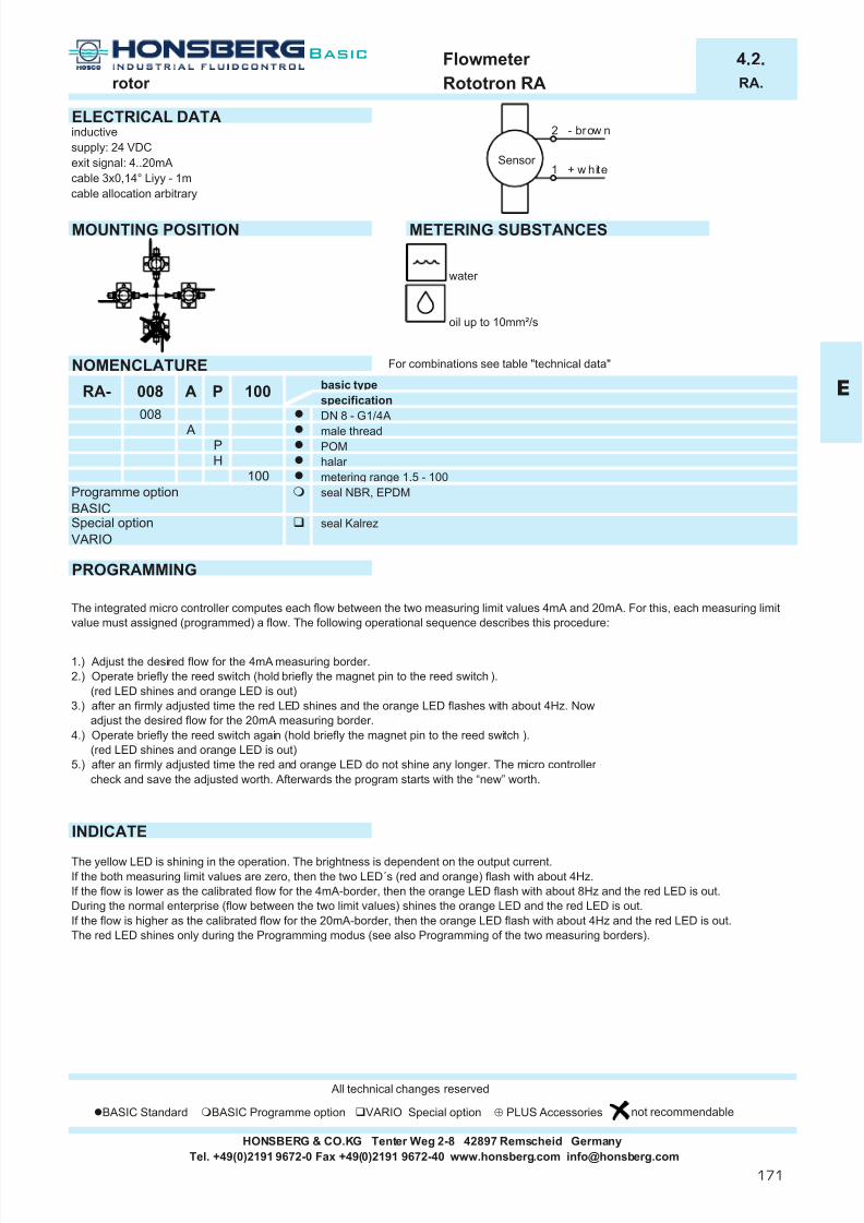
7/22/2019 General Honsberg
http://slidepdf.com/reader/full/general-honsberg 173/347
Flowmeter 4.2.rotor Rototron RA RA.
ELECTRICAL DATAinductivesupply: 24 VDCexit signal: 4..20mAcable 3x0,14° Liyy - 1mcable allocation arbitrary
MOUNTING POSITION METERING SUBSTANCES
water
oil up to 10mm²/s
NOMENCLATURE For combinations see table "technical data"
basic typespecificationDN 8 - G1/4Amale threadPOMhalar metering range 1.5 - 100seal NBR, EPDM
BASICseal Kalrez
VARIO
PROGRAMMING
INDICATE
All technical changes reserved
BASIC Standard BASIC Programme option VARIO Special option ⊕ PLUS Accessories not recommendable
RA- 008 A P 100
P
Special option
The yellow LED is shining in the operation. The brightness is dependent on the output current.If the both measuring limit values are zero, then the two LED´s (red and orange) flash with about 4Hz.If the flow is lower as the calibrated flow for the 4mA-border, then the orange LED flash with about 8Hz and the red LED is out.During the normal enterprise (flow between the two limit values) shines the orange LED and the red LED is out.If the flow is higher as the calibrated flow for the 20mA-border, then the orange LED flash with about 4Hz and the red LED is out.The red LED shines only during the Programming modus (see also Programming of the two measuring borders).
HONSBERG & CO.KG Tenter Weg 2-8 42897 Remscheid GermanyTel. +49(0)2191 9672-0 Fax +49(0)2191 9672-40 www.honsberg.com [email protected]
H
Programme option100
The integrated micro controller computes each flow between the two measuring limit values 4mA and 20mA. For this, each measuring limitvalue must assigned (programmed) a flow. The following operational sequence describes this procedure:
1.) Adjust the desired flow for the 4mA measuring border.2.) Operate briefly the reed switch (hold briefly the magnet pin to the reed switch ).
(red LED shines and orange LED is out)3.) after an firmly adjusted time the red LED shines and the orange LED flashes with about 4Hz. Now
adjust the desired flow for the 20mA measuring border.4.) Operate briefly the reed switch again (hold briefly the magnet pin to the reed switch ).
(red LED shines and orange LED is out)5.) after an firmly adjusted time the red and orange LED do not shine any longer. The micro controller
check and save the adjusted worth. Afterwards the program starts with the “new” worth.
008 A
2 - brow n
1 + w hiteSensor
E
Basic
171
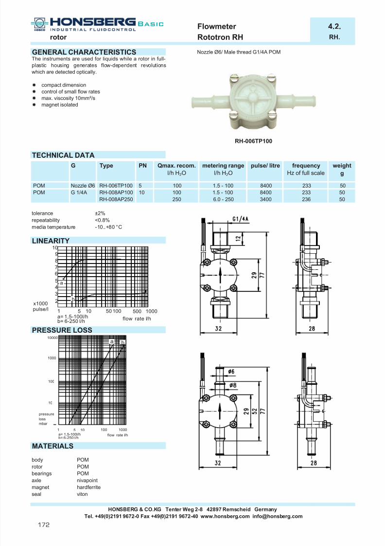
7/22/2019 General Honsberg
http://slidepdf.com/reader/full/general-honsberg 174/347
Flowmeter 4.2.rotor Rototron RH RH.
GENERAL CHARACTERISTICS Nozzle Ø6/ Male thread G1/4A POM
TECHNICAL DATA
tolerance ±2%repeatability <0.8%media temperature -10..+80 °C
LINEARITY
PRESSURE LOSS
MATERIALS
body POMrotor POMbearings POMaxle nivapointmagnet hardferriteseal viton
HONSBERG & CO.KG Tenter Weg 2-8 42897 Remscheid GermanyTel. +49(0)2191 9672-0 Fax +49(0)2191 9672-40 www.honsberg.com [email protected]
frequencyHz of full scale
RH-008AP2505050250 6.0 - 250 3400 236
100 1.5 - 100 8400 233POM G 1/4A RH-008AP100 10
weightg
POM Nozzle Ø6 RH-006TP100 5 100 1.5 - 100 8400 233 50
The instruments are used for liquids while a rotor in full-plastic housing generates flow-dependent revolutionswhich are detected optically.
compact dimensioncontrol of small flow ratesmax. viscosity 10mm²/smagnet isolated
Qmax. recom.l/h H2O
metering rangel/h H2O
RH-006TP100
pulse/ litreG Type PN
10000
1000
100
10
a b
flow rate l/h1 5 10 100 1000
pressurelossmbar
a= 1,5-100l/hb= 6-250 l/h
flow rate l/ha= 1,5-100l/hb= 6-250 l/h
1 5 10 50 100 500 1000
x1000pulse/l
98765
432
10
b
a
Basic
172

7/22/2019 General Honsberg
http://slidepdf.com/reader/full/general-honsberg 175/347
Flowmeter 4.2.rotor Rototron RH RH.
ELECTRICAL DATAhall sensor, contactlesssupply: 4,5..24 VDC / l - out 15 mA of 24 V outputexit signal: precise rectanglecable 3x0,14° Liyy - 1m
MOUNTING POSITION METERING SUBSTANCES
water
oil up to 10mm²/s
NOMENCLATURE For combinations see table "technical data"
basic typespecificationDN 6 - nozzle Ø6DN 8 - G1/4Anozzlemale threadPOMmetering range 1.5 - 100metering range 6.0 - 250seal NBR, EPDM
BASICseal Kalrez
VARIO
All technical changes reserved
BASIC Standard BASIC Programme option VARIO Special option ⊕ PLUS Accessories not recommendable
Tel. +49(0)2191 9672-0 Fax +49(0)2191 9672-40 www.honsberg.com [email protected]
006 T P
HONSBERG & CO.KG Tenter Weg 2-8 42897 Remscheid Germany
100
Programme option
Special option
006RH-
AP
T008
250100
2 - brow n
3 green
1 + w hiteSensor
E
Basic
173

7/22/2019 General Honsberg
http://slidepdf.com/reader/full/general-honsberg 176/347
flowmeter 4.2.rotor Rototron RRI RRI.
GENERAL CHARACTERISTICS Female- / male thread G3/8 / G1, nozzle Ø11 PVDF
RRI-025GVQRRI-010GVQ
TECHNICAL DATA
The measurements were taken from left to right with the sensor stationary using water at 25°C.
(1) measuring range total(2) measuring range specified(3) measuring range non linear (4) extended operating range
increase abrasion, ∆p > 0.5 bar (5) pulse/litre (specification on the
identification plate on each sensor)(6) average pulse/litre(7) tolerance ±3% of the measured value(8) variation ±10% of pulse/litre data (5) in the charge(9) reproducibility ( ±1% of full scale )
is the repetive accuracy of frequency relatedto l/min
(10) frequency max. related to the applicablemeasuring range up to approx 0.5 bar pressure loss over the Sensor
media temperature max. 60 °C
MATERIALS
housing Questra /PPS (Fortron 1140L4)
rotor PVDF / 1.4310 RRI-010Gbearings Iglidur X RRI-010Aaxle ceramic Zr02-TZP RRI-010Tseal viton RRI-025Gno medium contact PVC cable RRI-025A
1.4305, 1.4301 RRI-025T
material options see nomenclature * dimension F at Namur 8 mm cancel!
HONSBERG & CO.KG Tenter Weg 2-8 42897 Remscheid GermanyTel. +49(0)2191 9672-0 Fax +49(0)2191 9672-40 www.honsberg.com [email protected]
G Type Hmm
50
96707070
122176
Lmm
L1mm
8484
-
Emm
16,516,516,5 38
22
Xmm
1214
252 0.55
SWmm
22
420
Bmm
29
120 4-100 6-100 4- 6
1216 0.5516 72 3- 60 5- 60 3- 5 607 0.55
5050
D N 2 5 G1
D N 1 0 G3/8
70
7070
D N 2 5 G1 3- 30
50
2- 316 36 2- 30
RRI-025...160 16
2929535353
1102323
Dmm
--
11
Cmm
12,512,512,5
-30
27,527,527,5
0.4-2 1755 0.20
-
F *mm
3838
23
5050
0.2016 12 0.2-10 2.0-10 0.2-2 3345 0.20
weightkg
(1) (2) (3) (6)
Qmax.recom .
l/min H2O
1.8 0.1- 1.5 0.5- 1.5
G PNbar
16
D N 1 0 G3/8
Type
RRI-010...020RRI-010...050RRI-010...070
333333
383838
21181845
The sensor consists of a rotor vane that is rotated by thespeed of the flowing medium. The speed of rotation isproportional to the volume flow per unit time. The rotationof the rotor is dedektiert by a inductive sensor.
no magnet partslarge wear liberty by high-qualityceramic axle and ceramic bearingsoutput circuit PNP, NPN or Namur no straight line in-out necessaryeasy measurement of flow ratesinherently safe propertiesmodular construction with the most versatileconnection systemsconnections can be plugged and rotated
frequencyHz of full
scale
(10)255
metering rangel/min H2O
pulse/ litre
0.1-0.5 10200
RRI-025...080RRI-025...120
558351608607
16 16.8 0.4-12 2.0-12
Hz
l / min
(8)
(9)
(2)(1)
(3)(4)
pulse / litre
l / min
(8) (9)
(6) (5)
(7)
(2)(1)
(3)
(4)
Basic
174

7/22/2019 General Honsberg
http://slidepdf.com/reader/full/general-honsberg 177/347
flowmeter 4.2.rotor Rototron RRI RRI.
ELECTRICAL DATAquiescent current consumption 10mA / Namur max. 7mAmax. output current 200mA / Namur max. 7mAsensor connection 2m cable or conection at
locking plugs M12x1, 4-poleshort-circuit proof yes
reverse polarity proof yesprotection class IP67
MOUNTING POSITION METERING SUBSTANCES
water air/gasses option ball bearing
oil up to 10mm²/s
NOMENCLATURE For combinations see table "technical data"
basic typespecificationDN 010DN 025female threadmale threadhose nozzleconnection material PVDFconnection material brass Ms58 nickel platedconnection material stainless steel 1.4305housing material Questra/PPShousing material PVDFDN 10 housing material PPS with transparent cover PSUDN 25 housing material Questra with transparent cover PCflow diameter Ø 2flow diameter Ø 5flow diameter Ø 7flow diameter Ø 8flow diameter Ø12flow diameter Ø16seal vitonseal EPDMseal NBRrotor with 10 clamprotor with 2 clamprotor with 5 clampclamp materal stainless steal 1.4310clamp materal titaniumPNP outputNPN outputNamur outputouput at suburb electronics (e.g. omni-RR)2 m cableconnection at locking plugs M12x1, 4-pole
special applications: Switching output, frequency converter, current output and omni/flex processor COMBINATIONSomni-RR further transformerslocal electronic unit, Flex switching and frequency exit, 0..10V or 4..20mA, pnp, npn2xNPN and PNP switch ESA1 electronic monitoring unit4(0)..20mA output ESK2 2 switchpoints - supply 24 V DCgraphical LCD display ESK3 1 switchpoint - supply 230 V ACwith flashing LED conceived for safety-relevant applicationsprogram ring EFFS switch output
EFFI current output 4(0)..20mA
EFFF frequency output All technical changes reserved
BASIC Standard BASIC Programme option VARIO Special option ⊕ PLUS Accessories not recommendable
HONSBERG & CO.KG Tenter Weg 2-8 42897 Remscheid GermanyTel. +49(0)2191 9672-0 Fax +49(0)2191 9672-40 www.honsberg.com [email protected]
S
A
KE
NP
TK
050210
NEV
160120080070050020
A
RRI- 010 G V Q 020 V 10 K P K010025
G AT
VMK
QV
brown
black
blue
1
4
3
+ 5 . .30 VDC
signal
0 Vz
PN P
brown
blue
+ 7..12 VDC
0 V
NAMUR
Z
brown
black
blue
1
4
3
+ 5..30 VDC
signal
0 V
z
NPN
E
Basic
175

7/22/2019 General Honsberg
http://slidepdf.com/reader/full/general-honsberg 178/347
flowmeter 4.2.rotor Rototron RRH RRH.
GENERAL CHARACTERISTICS Female- / male thread G3/8 / G1 brass / stainless steel
RRH-025GMM
RRH-010GMMTECHNICAL DATA
The measurements were taken from left to right with the sensor stationary using water at 25°C.
(1) measuring range total(2) measuring range specified(3) measuring range non linear (4) extended operating range
increase abrasion, ∆p > 0.5 bar (5) pulse/litre (specification on the
identification plate on each sensor)(6) average pulse/litre(7) tolerance ±3% of the measured value(8) variation ±10% of pulse/litre data (5) in the charge(9) reproducibility ( ±1% of full scale )
is the repetive accuracy of frequency relatedto l/min
(10) frequency max. related to the applicablemeasuring range up to approx 0.5 bar pressure loss over the Sensor
media temperature max. 100 °C
MATERIALShousing Ms58 nickel plat. or 1.4305rotor PVDF with magnet RRH-010Gbearings Iglidur X RRH-010Aaxle ceramic Zr02-TZP RRH-025Gseal viton RRH-025A
no medium contact PVC cable * dimension F at Namur 8 mm cancel!1.4305, 1.4301
material options see nomenclature
HONSBERG & CO.KG Tenter Weg 2-8 42897 Remscheid GermanyTel. +49(0)2191 9672-0 Fax +49(0)2191 9672-40 www.honsberg.com [email protected]
The sensor consists of a rotor vane that is rotated by thespeed of the flowing medium. The speed of rotation isproportional to the volume flow per unit time. The rotationof the rotor is dedektiert by a Hall-sensor.
metal housing, with Hall-Sensor large wear liberty by high-qualityceramic axle and ceramic bearingsoutput circuit PNP, NPN or Namur no straight line in-out necessaryeasy measurement of flow ratesinherently safe propertiesmodular construction with the most versatileconnection systemsconnections can be plugged and rotated
183827,5 3325
122
pulse/ litreG PNbar
Type
0.5- 1.5 0.1-0.5100
weightkg
(1) (2) (3) (6)
Qmax.recom .
l/min H2O
metering rangel/min H2O
4955 0.60100 12 0.2-10 2.0-10 0.2-2 1632
1.8 0.1- 1.5
0.4-2 860 0.60172100 16.8 0.4-12 2.0-12
33 3838
0.60
Xmm121418
1.90
F *mm38
D N 1 0 G3/8
D N 2 5 G1 2- 3 544
5- 60100 36 2- 30
Type
6-100
Cmm
50
3- 30
L1mm84
Lmm
Hmm50
1.90100
3- 5
10
1.90
SWmm2222
Bmm29
532323
110
Emm16,516,5
53
12,512,529
27,550
707050 84
G3/8
G1 7070
GDN
RRH-025...120RRH-025...160
3- 60120
100 724-100
frequencyHz of full
scale
(10)124272
272295210
RRH-010...020RRH-010...050RRH-010...070RRH-025...080
1264- 6295
Hz
l / min
(8)
(9)
(2)(1)
(3)(4)
pulse / litre
l / min
(8) (9)
(6) (5)
(7)
(2)(1)
(3)
(4)
Basic
176

7/22/2019 General Honsberg
http://slidepdf.com/reader/full/general-honsberg 179/347
flowmeter 4.2.rotor Rototron RRH RRH.
ELECTRICAL DATAquiescent current consumption 30mAmax. output current 100mAsensor connection 2m cable or conection at
locking plugs M12x1, 4-poleshort-circuit proof ja
reverse polarity proof japrotection class IP67
MOUNTING POSITION METERING SUBSTANCES
water air/gasses option ball bearing
oil up to 10mm²/s
NOMENCLATURE For combinations see table "technical data"
basic typespecificationDN 010DN 025female threadmale threadconnection material brass Ms58 nickel platedconnection material stainless steel 1.4305housing material brass Ms58 nickel platedhousing material stainless steel 1.4305flow diameter Ø 2flow diameter Ø 5flow diameter Ø 7flow diameter Ø 8flow diameter Ø12flow diameter Ø16seal vitonseal EPDMseal NBRseal Kemrazrotor with 5 magnetrotor with 2 magnetrotor material PVDFPNP outputNPN outputNamur outputouput at suburb electronics (e.g. omni-RR)2 m cableconnection at locking plugs M12x1, 4-pole
special applications: Switching output, frequency converter, current output and omni/flex processor
COMBINATIONS
omni-RR further transformerslocal electronic unit, Flex switching and frequency exit, 0..10V or 4..20mA, pnp, npn2xNPN and PNP switch ESA1 electronic monitoring unit4(0)..20mA output ESK2 2 switchpoints - supply 24 V DCgraphical LCD display ESK3 1 switchpoint - supply 230 V ACwith flashing LED conceived for safety-relevantprogram ring applications
EFFS switch outputEFFI current output 4(0)..20mAEFFF frequency output
All technical changes reserved
BASIC Standard BASIC Programme option VARIO Special option ⊕ PLUS Accessories not recommendable
HONSBERG & CO.KG Tenter Weg 2-8 42897 Remscheid GermanyTel. +49(0)2191 9672-0 Fax +49(0)2191 9672-40 www.honsberg.com [email protected]
PN
050
K05
020KM
KM
AG
025010
RRH- 010 G M M 020 V 05 V P K
070080120160
VEN
02V
SK
E A
brown
black
blue
1
4
3
+ 10..30 VDC
signal
0 Vz
PNP
brown
blue
+ 7..12 VDC
0 V
NAMUR
Z
brown
black
blue
1
4
3
+ 10..30 VDC
Au sgan gssign al
0 V
z
NPN
E
Basic
177

7/22/2019 General Honsberg
http://slidepdf.com/reader/full/general-honsberg 180/347
flowmeter 4.2.rotor Rototron RRO RRO.
GENERAL CHARACTERISTICS Female- / male thread G3/8 / G1, nozzle Ø11 PVDF
RRO-025GVV
RRO-010GVVTECHNICAL DATA
The measurements were taken from left to right with the sensor stationary using water at 25°C.
(1) measuring range total(2) measuring range specified(3) measuring range non linear (4) extended operating range
increase abrasion, ∆p > 0.5 bar (5) pulse/litre (specification on the
identification plate on each sensor)(6) average pulse/litre(7) tolerance ±3% of the measured value(8) variation ±10% of pulse/litre data (5) in the charge(9) reproducibility ( ±1% of full scale )
is the repetive accuracy of frequency relatedto l/min
(10) frequency max. related to the applicablemeasuring range up to approx 0.5 bar pressure loss over the Sensor
media temperature max. 60 °C
MATERIALShousing PVDFrotor PVDF RRO-010Gbearings Iglidur X RRO-010Aaxle ceramck Zr02-TZP RRO-010Tseal viton RRO-025G
no medium contact PVC cable RRO-025A1.4305, 1.4301 RRO-025T
material options see nomenclature * dimension F at Namur 8 mm cancel!
HONSBERG & CO.KG Tenter Weg 2-8 42897 Remscheid GermanyTel. +49(0)2191 9672-0 Fax +49(0)2191 9672-40 www.honsberg.com [email protected]
The sensor consists of a rotor vane that is rotated by thespeed of the flowing medium. The speed of rotation isproportional to the volume flow per unit time. The rotationof the rotor is dedektiert by a optical sensorr.
with optical sensor large wear liberty by high-qualityceramic axle and ceramic bearingsoutput circuit PNP or NPNno straight line in-out necessaryeasy measurement of flow ratesinherently safe propertiesmodular construction with the most versatileconnection systemsconnections can be plugged and rotated
2118
1845
Qmax.recom .
l/min H2O
metering rangel/min H2O
pulse/ litreG PNbar
Type
16
G
weightkg
(1) (2) (3) (6)
frequencyHz of full
scale
(10)1.8 0.1- 1.5 0.5- 1.5 0.1-0.5
16 12 0.2-10 2.0-100.4-2 1703 0.20
11720 0.200.2-2 2960
293493341
27,5
27,527,5
0.20
33
3333
38
3838-302323
--
11-
12,512,512,523
RRO-025...120RRO-025...160
3- 30
50
Type
2- 3
G3/85050
50
D N 1 0 G3/8
D N 2 5 G1
Bmm
2656-100 4- 6
Cmm
Dmm
D N 2 5
16 36
16
D N 1 0
120 4-100
G1
122176
2929
5353
1102953
0.5516 72 3- 60 5- 60 3- 5 588 0.55
2- 30588
0.55
SWmm2222
Xmm1214
442
F *mm38
-
Emm16,516,516,5 38
38
70
Lmm
L1mm848496
70
7070
70
70
Hmm50
50
545
RRO-010...020RRO-010...050RRO-010...070RRO-025...080 1090
16 16.8 0.4-12 2.0-12
Hz
l / min
(8)
(9)
(2)(1)
(3)(4)
pulse / litre
l / min
(8) (9)
(6) (5)
(7)
(2)(1)
(3)
(4)
Basic
178

7/22/2019 General Honsberg
http://slidepdf.com/reader/full/general-honsberg 181/347
flowmeter 4.2.rotor Rototron RRO RRO.
ELECTRICAL DATAquiescent current consumption 30mAmax. output current 100mAsensor connection 2m cable or conection at
locking plugs M12x1, 4-poleshort-circuit proof yes
reverse polarity proof yesprotection class IP67
MOUNTING POSITION METERING SUBSTANCES
water air/gasses option ball bearing
oil up to10mm²/s aggressive liquids
NOMENCLATURE For combinations see table "technical data"
basic typespecificationDN 010DN 025female threadmale threadhose nozzleconnection material PVDFconnection material brass Ms58 nickel platedconnection material stainless steel 1.4305housing material PVDFflow diameter Ø 2flow diameter Ø 5flow diameter Ø 7flow diameter Ø 8flow diameter Ø12flow diameter Ø16seal vitonseal EPDMseal NBRseal KemrazPNP outputNPN outputouput at suburb electronics (e.g. omni-RR)2 m cableconnection at locking plugs M12x1, 4-pole
special applications: Switching output, frequency converter, current output and omni/flex processor
COMBINATIONS
omni-RR further transformerslocal electronic unit, Flex switching and frequency exit, 0..10V or 4..20mA, pnp, npn2xNPN and PNP switch ESA1 electronic monitoring unit4(0)..20mA output ESK2 2 switchpoints - supply 24 V DCgraphical LCD display ESK3 1 switchpoint - supply 230 V ACwith flashing LED conceived for safety-relevantprogram ring applications
EFFS switch outputEFFI current output 4(0)..20mAEFFF frequency output
All technical changes reserved
BASIC Standard BASIC Programme option VARIO Special option ⊕ PLUS Accessories not recommendable
HONSBERG & CO.KG Tenter Weg 2-8 42897 Remscheid GermanyTel. +49(0)2191 9672-0 Fax +49(0)2191 9672-40 www.honsberg.com [email protected]
K
020V
KMV
T AG
025010
KV 020 V PRRO- 010 G V
050070080120160
VEN
PNE
SK
brown
black
blue
1
4
3
+ 24 V DC ±10%
signal
0 Vz
PNP
brown
black
blue
1
4
3
+ 24 V DC ±10%
signal
0 V
z
NPN
E
Basic
179

7/22/2019 General Honsberg
http://slidepdf.com/reader/full/general-honsberg 182/347
Flowmeter 4.2.rotor Rototron RR.-032 RR32
GENERAL CHARACTERISTICS Assembly clamp, assembly screwed-in probe,assembly welded pruning
RRI-032RMH000
RRI-032MHH065TECHNICAL DATA
The measurements were taken from left to right with the sensor stationary using water at 25°C.
(1) measuring range total(2) measuring range specified(3) measuring range non linear (4) extended operating range
increase abrasion, ∆p > 0.5 bar (5) pulse/litre (specification on the identification plate on each sensor)(6) average pulse/litre(7) tolerance ±3% of the measured value(8) variation ±10% of pulse/litre data (5) in the charge(9) reproducibility ( ±1% of full scale )
is the repetive accuracy of frequency related to l/min(10) frequency max. related to the applicable measuring range up to
approx 0.5 bar pressure loss over the Sensor
media temperature plastic max.60°C , stainless steel max.100°Cpressure PN10
MATERIALS
RRI (induktive sensor) RRH (hall sensor)
housing plastic PVC stainless steel 1.4305assembly clamp plastic PP plastic PProtor PVDF / stainless steel 1.4310 PVDF / magnetbearings Iglidur X Iglidur Xaxle ceramic Zr02-TZP ceramic Zr02-TZPseal viton vitonno medium contact PVC cable PVC cable
brass Ms58 nickel plated brass Ms58 nickel plated
HONSBERG & CO.KG Tenter Weg 2-8 42897 Remscheid GermanyTel. +49(0)2191 9672-0 Fax +49(0)2191 9672-40 www.honsberg.com [email protected]
1.4
60 - 300220 15 - 200
1.31.2
0.834 0.924
17,5
weightkg
(6)15 - 30 90 0.8
pulse/ litre
(3)
frequencyHz of full
scale
(10)300
48
50 - 100
15 - 6025 - 80
The sensor consists of a rotor vane that is rotated by thespeed of the flowing medium. The speed of rotation isproportional to the volume flow per unit time. The signalsare relayed by a variety of sensors, depending on thehousing materials emploied.
simple and economical flowmeter for pipe diametersfrom 32mm to 150mmproduced in plastic (stainless steel optional)Quickly fitted using the clamp mount. Evenretrospective fitting is easy!
DN metering rangel/min H2O
(1) (2)
Type Qmax.recom .
l/min
15 - 30030 - 200RR.-032MH032
50 480 25 - 400 80 - 400360
RR.-032MH050
3240
65 600
100 1200
40 - 500 100 - 500 40 - 10080 840 50 - 700 100 - 700
85 - 1000 100 - 1000 85 - 100 10,5RR.-032MH100 175
RR.-032MH040 240227200204
RR.-032MH065RR.-032MH080
Hz
l / min
(8)
(9)
(2)(1)
(3)(4)
pulse / litre
l / min
(8) (9)
(6) (5)
(7)
(2)(1)
(3)
(4)
Basic
180

7/22/2019 General Honsberg
http://slidepdf.com/reader/full/general-honsberg 183/347
Flowmeter 4.2.rotor Rototron RR.-032 RR32
DIMENSIONS
assembly clamp saddle with pipe and sleeve RR.-032MH…
assembly clamp saddle RR.-032BB…
customer
assembly welded pruning RR.-032RM… assembly screwed-in probe RR.-032VK...
customer
customer
MOUNTING
HONSBERG & CO.KG Tenter Weg 2-8 42897 Remscheid GermanyTel. +49(0)2191 9672-0 Fax +49(0)2191 9672-40 www.honsberg.com [email protected]
128 61DN 80 90 202 514,3
1,9 31
178154DN 65 75 3,656
DN 100
DN 150 160 130 180
DN 80 90 90 156
diameter
DN 40 50DN 32 40 142
49
36156 43
5,3 166
2,4
H
75 80
diameter B63 70
DN 65
nominalD
164
6681
DN 125 140 125 172DN 100 110 100
55 26
92 4479
3138
65
160 7,7 180 91
The Flowmeters are mounted as probes in a T-piece or in a mounting clamp; and marked for the correct insertion depth. The sensor mounting direction is longitudinally to the turbine wheel and is marked with arrows on the face of the probe. (With the electronics mounted,the direction of flow is longitudinal to the electronics housing. A deviation of up to ±3° in the angular orientation does not affect themeasurement. The sensor must be mounted with inlet and outlet sections of approx. 10 x the pipe diameter to avoid swirls and turbulence.The best mounting orientation (low contamination, good venting) is for upward flow direction or horizontal pipe route and an inclined sensor position of 45°.
DN 50
166
145
76DN 125 140 6,7 172 159
107
132145
232
nominal D
145DN 50
110156
63 3,0 145
H
L L1 L2 L3s
180312287
86DN 150
E
Basic
181

7/22/2019 General Honsberg
http://slidepdf.com/reader/full/general-honsberg 184/347
Flowmeter 4.2.rotor Rototron RR.-032 RR32
ELECTRICAL DATARRI (induktive sensor) RRH (hall sensor)
supply voltage PNP/NPN 5..30 VDC PNP/NPN 10..30 VDCNamur 7..12 VDC Namur 7..12 VDC
quiescent current consumption 10mA / Namur max. 7mA 30mAmax. output current 200mA / Namur max. 7mA 100mAsensor connection 2m cable or conection at 2m cable or conection at
locking plugs M12x1, 4-pole locking plugs M12x1, 4-poleshort-circuit proof yes yesreverse polarity proof yes yesprotection class IP67 IP67MOUNTING POSITION METERING SUBSTANCES
water
NOMENCLATUREbasic typespecificationFlowmeter with inductive sensor Flowmeter with hall sensor screwed cap G1 1/4
clamp saddle with pipe and sleeve at PVCscrewed-in probe G1 1/4 with clamp ring and screwed capclamp saddle PPwelded pruning stainless steel 1.4305probe material PVCprobe material stainless steel 1.4305(at screwed-in probe or welded pruning)DN 032DN 040DN 050DN 065DN 080DN 100DN 125DN 150seal Vitonseal EPDMseal NBRrotor with 10 stainless steel clambs (RRI)rotor with 10 titanium clambs (RRI)rotor with 5 magnet (RRH)PNP outputNPN outputNamur outputouput at suburb electronics (e.g. omni-RR)2 m cableconnection at locking plugs M12x1, 4-pole
special applications: Switching output, frequency converter, current output and omni/flex processor
All technical changes reserved
BASIC Standard BASIC Programme option VARIO Special option ⊕ PLUS Accessories not recommendable
HONSBERG & CO.KG Tenter Weg 2-8 42897 Remscheid GermanyTel. +49(0)2191 9672-0 Fax +49(0)2191 9672-40 www.honsberg.com [email protected]
EV
150
100125
080065050040032
HRRI- 032
RRH-RRI-
032MH
BBRM
VK
05M
N
NP
E A
SK
10T10K
000
032 V
KH
MH 10K P K
The pipe which accepts the Flowmeter should becompletely filled under all operating conditions since air bubbles significantly affect the measurement results. Withfilling processes the valve should be fitted after thesensor. You should allow for a run-up time of approx. 0.5s and a delay time of several seconds.
air bubbles!
sediment!
brown
black
blue
1
4
3
+
signal
0 Vz
PNP
brown
black
blue
1
4
3
+
signal
0 V
z
NPN
brown
blue
+
0 V
NAMUR
Z
Basic
182

7/22/2019 General Honsberg
http://slidepdf.com/reader/full/general-honsberg 185/347
Flow Indicator 5.1.turbine Visoflow HV-...GM HV.
GENERAL CHARACTERISTICS Female thread G1/4 to G1 brass
TECHNICAL DATA HV-015GM
pressure PN 10media temperature max. 100°Caverage pressure loss 0.2 bar at Qmax.
MATERIALS
housing PA 66connector brass
turbine PA 66 redaxle PA 66bearing steinless steel sphereglass temperated glassseal NBR
MOUNTING POSITION
METERING SUBSTANCES NOMENCLATURE
basic typewater specification
DN 8 - G1/4DN 10 - G3/8
oil DN 15 - G1/2With higher viscosity instruments DN 20 - G3/4tend to higher starting values of the turbine. DN 25 - G1
female threadbrass connector
All technical changes reserved
BASIC Standard BASIC Programme option VARIO Special option ⊕ PLUS Accessories not recommendable
HONSBERG & CO.KG Tenter Weg 2-8 42897 Remscheid GermanyTel. +49(0)2191 9672-0 Fax +49(0)2191 9672-40 www.honsberg.com [email protected]
114
92
The flow indicators Visoflow provide a reliable indication of transparent liquids. A signal red turbine wheel is driven bythe flow and by the relevant revolutions offers indicativeinformation of the momentary flow rate involved. Theinstruments offer a 360° view and promise longoperational life span due to the design of turbine wheeland bearing concept.
bidirectionalvisibility of turbine 360°
G 3/4G 1
b r a s s
Qmax. rec.l/min H2O
610
284646
n o m i n a l
d i a m e t e r
46 7070
3646
153050
G
G 1/2
Type
HV-008GMHV-010GMHV-015GMHV-020GM 5.0
5.02.12.1
3.73.7
Bmm
2236
114
Amm
6692 60
60
Cmm
44
weightkg
0.110.180.180.600.60
SWmm
2028
008M008
015010
025020
G
HV-025GM
HV-
GM
3.0G 1/4G 3/8
start of turbine l/min
0.61.2
3.5
4.03.01.2
40 mm²/s 41-150 mm²/s2.5
H2O
4.0
E
Basic
183

7/22/2019 General Honsberg
http://slidepdf.com/reader/full/general-honsberg 186/347
Flowmeter 5.1.turbine Rototron RO-...TV RO.
GENERAL CHARACTERISTICS Nozzle Ø6.9 up to Ø16 PVDF
TECHNICAL DATA RO-012TV015
tolerance ±1%linearity ±1%repeatability ±1%media temperature max. 85°Caverage pressure loss 0.5 to 1bar at Qmax.
MATERIALS
wetted parts PVDFseal polymerebearings PVDF
MOUNTING POSITION ELECTRICAL DATAinfra red-opto-electricsupply 5..12 V DC 6..33 mAwith integrated wiring protectionexit signal 5..11 V square-wavefrequency 20-800 Hzcable 1 metre
METERING SUBSTANCES NOMENCLATUREbasic typespecification
water aggressive liquids nozzle Ø 6.9nozzle Ø10nozzle Ø12
oil up to 5mm²/s nozzle Ø16nozzle
Attention! For tranparent liquids only. PVDFmetering range 0.1 - 2 l/minmetering range 0.3 - 9 l/minmetering range 0.5 - 15 l/minmetering range 1.0 - 30 l/min
ACCESSORIES
For type RO-007TV a filtre FRP4174 is compulsory for protectionof the moving parts. Please order seperately.
All technical changes reserved
BASIC Standard BASIC Programme option VARIO Special option ⊕ PLUS Accessories not recommendable
The instruments are used for liquids while a turbine in full-plastic housing generates flow-dependent revolutionswhich are detected optically.
not straight inline/ outline requirementfull-plastic designfor transparent liquidsintegrated filter
0.5 - 151.0 - 30
metering rangel/min H2O
0.1 - 20.3 - 9
PNbar
66
010
016012
009
007RO-
VT
002
030015
60
1660
007 T V 002
600.100.12
80003200
1372811224
1200
weightkg
0.060.0922
20
Lmm
95112
Xmm
36000
dmm
pulse/litre
RO-012TV015 12106.9
filter µm
-RO-010TV009
RO-016TV030
Qmax. recom.l/min H2O
1.581223
Type
RO-007TV002
66
HONSBERG & CO.KG Tenter Weg 2-8 42897 Remscheid GermanyTel. +49(0)2191 9672-0 Fax +49(0)2191 9672-40 www.honsberg.com [email protected]
w hite
brow n (signal)
green(shielded)
Basic
184

7/22/2019 General Honsberg
http://slidepdf.com/reader/full/general-honsberg 187/347
Flowmeter 5.1.turbine Lineflow RRF RRF.
GENERAL CHARACTERISTICS Male thread G3/8A PA
TECHNICAL DATA
tolerance ±3% of readingrepeatability ±0,5% full scalemedia temperature -20..100°Cambient temperature max. 80°C
PRESSURE LOSS
MATERIALS
housing PA 12turbine PA 12bearings PTFE 15% graphite
HONSBERG & CO.KG Tenter Weg 2-8 42897 Remscheid GermanyTel. +49(0)2191 9672-0 Fax +49(0)2191 9672-40 www.honsberg.com [email protected]
G3/8A RRF-010AN010 14 1.0 - 102200
pulse / litre frequency outputHz
3300 55 - 550
The Hall effect flow rate sensor consists of a full plasticenclosure and linear turbine wheel. The revolutions of theturbine are magnetically sensed by an external hall sensor and processed to a stable frequency output. Theadvantage of this principle is the independence frompressure conditions and the optional mounting position.
high accuracy, low costoptional installation
G Type PNbar
metering rangel/min H2O
pressure losscode
weightg
G3/8A RRF-010AN005 14 0.5 - 5 6900 58 - 575 A 40 A 40
1000 33 - 500 B 4037 - 550 A 40G3/8A RRF-010AN015 14 1.0 - 15
G3/8A RRF-010AN030 14 2.0 - 30
1.2bar
l/min
3020100
0.8
0.4
0
A
B
E
Basic
185

7/22/2019 General Honsberg
http://slidepdf.com/reader/full/general-honsberg 188/347
Flowmeter 5.1.turbine Lineflow RRF RRF.
ELECTRICAL DATAinput power 5..24VDC at 8mAoutput NPN sinking open collector at 50mA max.(1 to 2,2K Ohm Pull-Up Resistor Required)(frequency output)cable 1 m or spade terminals 2.8/6.3 x 0.8mm
protection class cable IP 65spade terminals IP 00
MOUNTING POSITION METERING SUBSTANCES
a filter < 50µm is recommendedwater
oil up to 16mm²/s
NOMENCLATURE For combinations see table "technical data"
basic typespecification
nominal diameter DN 10 - G3/8Amale threadhousing material nylonmetering range 0,5- 5 l/minmetering range 1,0-10 l/minmetering range 1,0-15 l/minmetering range 1,0-30 l/mincablespade terminals
All technical changes reserved
BASIC Standard BASIC Programme option VARIO Special option ⊕ PLUS Accessories not recommendable
HONSBERG & CO.KG Tenter Weg 2-8 42897 Remscheid GermanyTel. +49(0)2191 9672-0 Fax +49(0)2191 9672-40 www.honsberg.com [email protected]
F
010 A
005N
ARRF
015010
N 005 K
K030
010
-
+
black
red
0 VDC
5..24 VDC
outputbrow n
1k..2,2kohms (+ ) customer supplied
Basic
186

7/22/2019 General Honsberg
http://slidepdf.com/reader/full/general-honsberg 189/347
Flowmeter 5.1.turbine Rototron RRT RRT.
GENERAL CHARACTERISTICS female thread G3/4 POM / brass
TECHNICAL DATA
tolerance ±3% EWmedia temperature -25..90°Cambient temperature -25..60°C
PRESSURE LOSS ELECTRICAL DATAHall-sensor NPN, NPN open collector supply voltage 5..24 VDC; max 26.4 VDCquiescent current consumption 10mAconection at locking plugs M12x1, 4-poleprotection class IP67
MATERIALS NOMENCLATURE
housing POM or brass nickel plated basic typeturbine ULTEM 1000 nature, PEI specification
Rubin DU-B , strotzium ferrite nominal diameter DN20 - G3/41.4125, Bronze bridges PTFE plated female thread
housing POMMOUNTING POSITION housing brass
range 1 - 50 l/minrange 2 - 80 l/minelectronic output NPN ocelectronic output NPNelectronic output Namur (only for housing plastic)electronic output 2-Leiter electronic output by local
METERING SUBSTANCES electronic ( e.g.omni-RRT )connection atlocking plugs M12x1, 4-pole
water electronic output by localelectronic ( e.g.omni-RRT )
All technical changes reserved
BASIC Standard BASIC Programme option VARIO Special option ⊕ PLUS Accessories not recommendable
RRT-020GM
In a metal enclosure a plastic turbine is arranged insaphire cups and provides flow-dependent revolutionswhich are magnetically detected by an externally arrangedHall sensor.
two different turbine applicationsmetal or plasticlong life stabilitylarge dynamic (range)
1 - 502 - 80
metering rangel/min H2O
1 - 502 - 80
PNbar
1010
0.60
150100150
weightkg
0.150.150.60
100
impulse/litre
RRT-020GM050RRT-020GP080
RRT-020GM080
Type
RRT-020GP050
100100
HONSBERG & CO.KG Tenter Weg 2-8 42897 Remscheid GermanyTel. +49(0)2191 9672-0 Fax +49(0)2191 9672-40 www.honsberg.com [email protected]
RRT- 020 G P 050 P S020
GPM
050080
MN
A
Z
E
S
-
NPN oc
1
4
3
black
blue
zsignal
0 V
+brow n
0 20 40 60 80
1
2
3pressure l oss/ bar
l/min
80l/min
50l/min
E
Basic
187

7/22/2019 General Honsberg
http://slidepdf.com/reader/full/general-honsberg 190/347
Flowmeter 5.1.turbine Rototron RRT1 RRT1.
GENERAL CHARACTERISTICS female thread G3/8 POM / brass
TECHNICAL DATA
tolerance ±3% EWmedia temperature -25..90°Cambient temperature -25..60°C
PRESSURE LOSS
MATERIALS
housing POM or brass nickel platedturbine ULTEM 1000 nature, PEI
Rubin DU-B , strotzium ferrite1.4125, Bronze bridges PTFE plated
HONSBERG & CO.KG Tenter Weg 2-8 42897 Remscheid GermanyTel. +49(0)2191 9672-0 Fax +49(0)2191 9672-40 www.honsberg.com [email protected]
In a metal enclosure a plastic turbine is arranged insaphire cups and provides flow-dependent revolutionswhich are magnetically detected by an externally arrangedHall sensor.
modular system with two different turbineapplicationseasy for installation and servicemodular system with check valve, filter and/or flow regulator large dynamic (range)
RRT1-010GM
RRT1-010GM080 100 2 - 80
10 2 - 80RRT1-010GM050 100 1 - 50
Type PNbar
metering rangel/min H2O
impulse/litre
RRT1-010GP050 10 1 - 50 100
weightkg
0.10150 0.10100 0.50150 0.50
RRT1-010GP080
0 20 40 60 80
1
2
3pressure loss / bar
l/min
80l/min
50l/min
Basic
188

7/22/2019 General Honsberg
http://slidepdf.com/reader/full/general-honsberg 191/347
Flowmeter 5.1.turbine Rototron RRT1 RRT1.
ELECTRICAL DATAHall-sensor NPN, NPN open collector supply voltage 5..24 VDC; max 26.4 VDCquiescent current consumption 10mAconection at locking plugs M12x1, 4-pole
protection class IP67
MOUNTING POSITION METERING SUBSTANCES
water
NOMENCLATUREbasic typespecification
nominal diameter DN 10 - G3/8female threadconnection brassconnection plastic POMhousing brasshousing plastic POMrange 1 - 50 l/minrange 2 - 80 l/minseal Vitonseal EPDMseal NBRelectronic output NPN open collector electronic output NPNelectronic output Namur ( only for housing plastic POM )electronic output 2-wireelectronic output by local electronic (e.g. omni-RRT1)connection at locking plugs M12x1, 4-poleconnection by local electronic (e.g. omni-RRT1)connection pureconnection with Filter ( intake )connection with check valve ( intake )connection pureconnection with flow regulator 3 l/min ( outlet )connection with flow regulator 5 l/min ( outlet )connection with flow regulator 6 l/min ( outlet )connection with flow regulator 8 l/min ( outlet )connection with flow regulator 10 l/min ( outlet )connection with flow regulator 12 l/min ( outlet )connection with flow regulator 15 l/min ( outlet )
special applications: Switching output, frequency converter, current output and omni/flex processor
OPTIONFlow regulator (options) Check valve (options)limiter flow rates 3 ; 5; 6 ; 8 ; 10 ; 12 ; 15 materials POM, NBRpressure range 2 - 10 bar max. differential 16 bar Filter (options)pressure mesh size 250µmtolerance ±15% materials POM, stainless steel 1.4301materials POM, NBR, stainless steel 1.4571
All technical changes reserved
BASIC Standard BASIC Programme option VARIO Special option ⊕ PLUS Accessories not recommendable
HONSBERG & CO.KG Tenter Weg 2-8 42897 Remscheid GermanyTel. +49(0)2191 9672-0 Fax +49(0)2191 9672-40 www.honsberg.com [email protected]
08060503O
RFO
-S
EZ ANM
NEV
080
010G
OP S O
M
G
PMP
050
RRT1- M P 050 V010
10
1512
NPN oc
1
4
3
black
blue
zsignal
0 V
+brow n
E
Basic
189
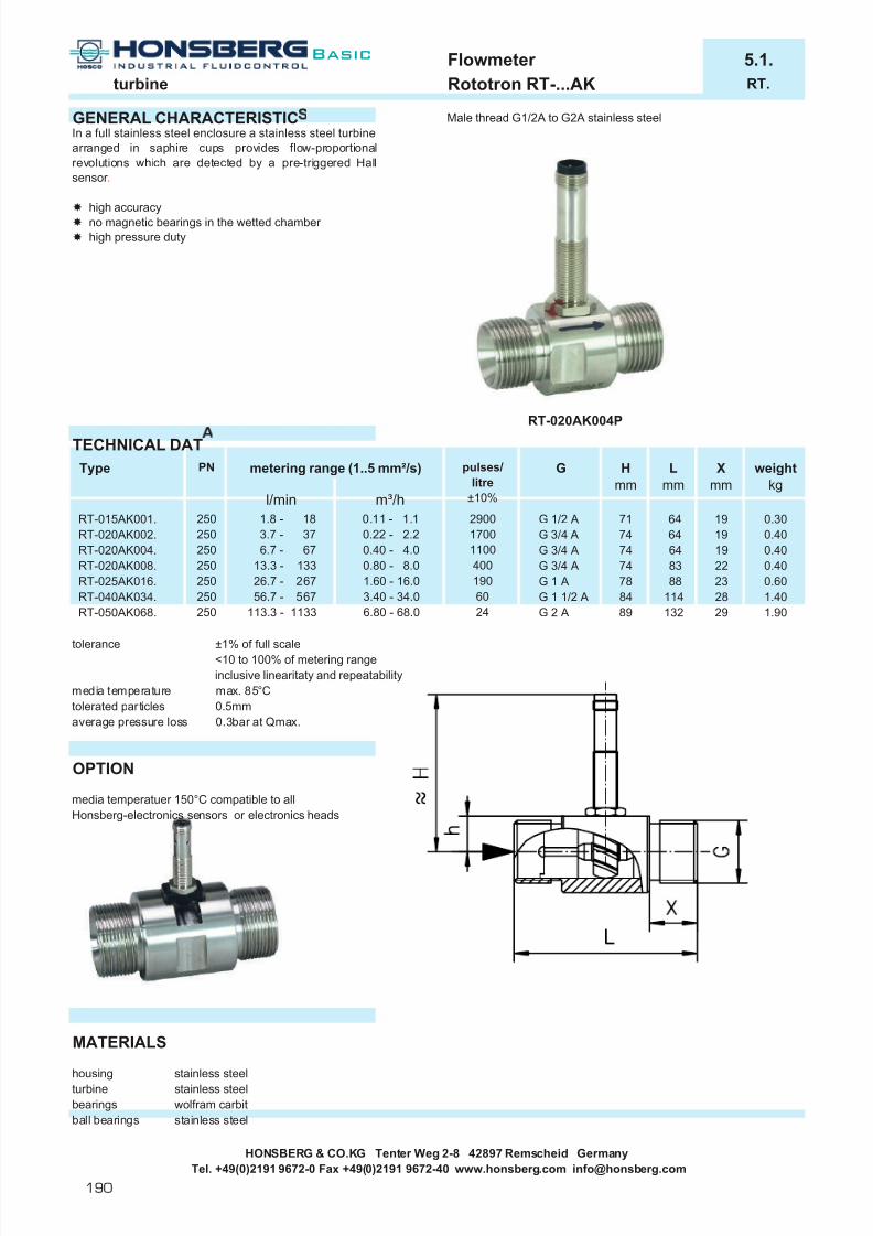
7/22/2019 General Honsberg
http://slidepdf.com/reader/full/general-honsberg 192/347
Flowmeter 5.1.turbine Rototron RT-...AK RT.
GENERAL CHARACTERISTIC Male thread G1/2A to G2A stainless steel
TECHNICAL DAT
tolerance ±1% of full scale<10 to 100% of metering rangeinclusive linearitaty and repeatability
media temperature max. 85°Ctolerated particles 0.5mmaverage pressure loss 0.3bar at Qmax.
OPTION
media temperatuer 150°C compatible to allHonsberg-electronics sensors or electronics heads
MATERIALS
housing stainless steelturbine stainless steelbearings wolfram carbitball bearings stainless steel
HONSBERG & CO.KG Tenter Weg 2-8 42897 Remscheid GermanyTel. +49(0)2191 9672-0 Fax +49(0)2191 9672-40 www.honsberg.com [email protected]
In a full stainless steel enclosure a stainless steel turbinearranged in saphire cups provides flow-proportionalrevolutions which are detected by a pre-triggered Hallsensor .
high accuracyno magnetic bearings in the wetted chamber high pressure duty
1.901.40
0.400.40
0.60
weightkg
0.300.40
Lmm
Xmm
64 19
RT-020AK004P
64 190.11 - 1.1 2900
1100
1.8 - 18250
Type
RT-015AK001.RT-020AK002. 250
PN metering range (1..5 mm²/s) pulses/litre
±10%l/min m³/h
74
RT-050AK068.
RT-020AK004.RT-020AK008.
RT-040AK034.RT-025AK016.
250 6.7 - 67 0.40 - 4.0
G Hmm
G 1/2 A 713.7 - 37 0.22 - 2.2 1700 G 3/4 A
G 3/4 A 74 64 19250 13.3 - 133 0.80 - 8.0 400 G 3/4 A 74 83 22250 26.7 - 267 1.60 - 16.0 190 G 1 A 78 88 23250 56.7 - 567 3.40 - 34.0 60 G 1 1/2 A 84 114 28250 113.3 - 1133 6.80 - 68.0 24 G 2 A 89 132 29
Basic
190

7/22/2019 General Honsberg
http://slidepdf.com/reader/full/general-honsberg 193/347
Flowmeter 5.1.turbine Rototron RT-...AK RT.
ELECTRICAL DAThall sensor, pre-triggered wiring 0.319 z=loadvoltage range 10-30 V DCcurrent 20 mA without loadmax. load 100 mAcontact for locking plug M12x1 , 4-pole
protection class IP 67MOUNTING POSITION METERING SUBSTANCES
water aggressive liquids
oil up to 5mm²/s
NOMENCLATURE For combinations see table "technical data".
basic typespecificationDN 15 - G1/2ADN 20 - G3/4ADN 25 - G1ADN 40 - G1 1/2ADN 50 - G2Amale threadstainless steel design0.11 - 1.1 m³/h0.22 - 2.2 m³/h0.40 - 4.0 m³/h0.80 - 8.0 m³/h1.60 - 16.0 m³/h3.40 - 34.0 m³/h6.80 - 68.0 m³/hPNPNPNexit by local electronic (e.g. omni-TTH)flange design
BASIC temperature max. 120°C (NPN)DN 80-300 PN16design for air/gasrange from 0.05 m³/hEX amplifier EEV1 product information 80.1.EEV1.Counter EEZ904 product information 83.1.EEZ904.
special applications: Switching output, frequency converter, current output and omni/flex processor
COMBINATIONS
omni-RT further transformerslocal electronic unit, Flex switching and frequency exit, 0..10V or 4..20mA, pnp, npn2xNPN and PNP switch ESA1 electronic monitoring unit4(0)..20mA output ESK2 2 switchpoints - supply 24 V DCgraphical LCD display ESK3 1 switchpoint - supply 230 V ACwith flashing LED conceived for safety-relevantprogram ring applications
EFFS switch outputEFFI current output 4(0)..20mAEFFF frequency output
All technical changes reserved
BASIC Standard BASIC Programme option VARIO Special option ⊕ PLUS Accessories not recommendable
HONSBERG & CO.KG Tenter Weg 2-8 42897 Remscheid GermanyTel. +49(0)2191 9672-0 Fax +49(0)2191 9672-40 www.honsberg.com [email protected]
Programme option
Special optionVARIO
025020
040
015RT- 015 A K 001 P
A
NP
n o m i n a l d i
10 x diam. as smoothingsection on inlet andoutlet
002
K
050
E
⊕
m e t e r i n g r a n g e
( 1 - 5
m m ² / s )
004008
001
034016
068
AccessoriesPLUS
NPN
1
4
3
black
blue
zoutput
0 V
+brow nPNP
1
4
3
black
blue zoutput
0 V
+brow n
E
Basic
191

7/22/2019 General Honsberg
http://slidepdf.com/reader/full/general-honsberg 194/347
Flowmeter 6.1.gear wheel Volutron VHZ-...GA/GK VHZ.
GENERAL CHARACTERISTICS Female thread G1/4 - G1 aluminium / stainless steal
TECHNICAL DATA
±3 % full skale MOUNTING(in reference to 20 mm²/s)±0.3%-25..80°Coptionally -25..120°C(only 2-wire-execution DN10-25)
MATERIALS
VHZ-...GA VHZ-010-025GK VHZ-008GKhousing aluminium anodized stainless steel 1.4404 stainless steel 1.4404gear and axle stainless steel 1.4462 stainless steel 1.4462 stainless steel 1.4462bearings Iglidur X Iglidur X stainless steel 1.4037/1.4016 /PVD platedseal viton viton Vitonsight glass glass ( only VHZO )
HONSBERG & CO.KG Tenter Weg 2-8 42897 Remscheid GermanyTel. +49(0)2191 9672-0 Fax +49(0)2191 9672-40 www.honsberg.com [email protected]
1.6VHZO-020GAVHZ-020GA
reproducebility Any installation position is possible and the the flow direction isindependent.Take care of a clean pipe line. With larger particles in flow theemployment of a filter of 30µm for protection is recommended.
6.31.6
VHZ-025GA
accuracy
VHZ-008GK 1.5VHZ-010GK 1.5
160200
0.02 - 20.1 - 6
0.02cm³=1Puls - max.833 Hz at 2l/min0.20cm³=1Puls - max.500 Hz at 6l/min
a l u m i n i u m
s . s .
VHZ-008GAG1/4G3/8G3/4G3/4G1G1/4G3/8
0.50.5VHZ-010GA 0.1 - 6
0.5 - 500.5 - 50
0.04cm³=1Puls - max.833 Hz at 2l/min
weightkg
Type frequencymetering rangel/min
G
media temperature
The Flowmeter VHZ was especially developed for themetering of viscous liquids.The units work volumetricallyas gear transmitters with high accuracy and full viscositystability.Gear wheel flow meter, with provides a linear frequencysignal by flow proportional revolution of a gear wheel andsensoring by a field biased Hall sensor. Viscositycompensated by volumetric operation.
operation independent of viscositylight and compact designfor cost sensitive application
PNbar
200200200100100
0.02 - 20.20cm³=1Puls - max.500 Hz at 6l/min2.00cm³=1Puls - max.417 Hz at 50l/min2.00cm³=1Puls - max.417 Hz at 50l/min
3.0 - 150 5.22cm³=1Puls - max.479 Hz at 150l/min
Basic
192

7/22/2019 General Honsberg
http://slidepdf.com/reader/full/general-honsberg 195/347
Flowmeter 6.1.gear wheel Volutron VHZ-...GA/GK VHZ.
DIMENSIONS
VHZ-008 / VHZ-010 VHZ-025
VHZ-008 G1/4VHZ-010 G3/8
VHZ-020
FUNCTIONAL DIAGRAMS
Noise level / flow rate
VHZ-008 VHZ-020The noise level of the VHZ-008 is <50db (A) in case of 2 l/min.
VHZ-010The noise level of the VHZ-010 is <50db (A) in case of 6 l/min.
VHZ-025The noise level of the VHZ-025 is <70db (A) in case of 150 l/min.
HONSBERG & CO.KG Tenter Weg 2-8 42897 Remscheid GermanyTel. +49(0)2191 9672-0 Fax +49(0)2191 9672-40 www.honsberg.com [email protected]
55
60
65
70
500 10 20 30 40 50
l/min
db (A)
E
Basic
193

7/22/2019 General Honsberg
http://slidepdf.com/reader/full/general-honsberg 196/347
Flowmeter 6.1.gear wheel Volutron VHZ-...GA/GK VHZ.
Gearwheel volume / flow rate
VHZ-008 VHZ-020
VHZ-010 VHZ-025
pressure loss / viscosity / flow rate
VHZ-008 VHZ-020
VHZ-010 VHZ-025
HONSBERG & CO.KG Tenter Weg 2-8 42897 Remscheid GermanyTel. +49(0)2191 9672-0 Fax +49(0)2191 9672-40 www.honsberg.com [email protected]
The volumetric displacement per gearwheel is a dimension for the for the functional accuracy of the unit.The max. tolerance related to fullrange is ±3%. All diagrams are based on a viscosity of 20mm²/s.
0,200
0,205
0,210
0,195
0,1900 2 3 4 5
cm 3
l/min
1 6
0,041
0,042
0,043
0,040
0,0390 1 1,5
cm 3
l/min
0,5 2
2,00
2,05
2,10
1,95
1,900 10 20 30 40 50
cm 3
l/min
5,20
5,30
5,40
5,10
5,000 30 60 90 120 150
cm 3
l/min
0 0.5 1 1.5 2
1
2
3
4pressure loss / bar
l/min
100mm²/s
34mm²/s
0 1 2 3 4 5 6
1
2
3
4
5pressure loss / bar
l /min
1000mm²/s
100mm²/s
34mm²/s
10mm²/s
0 10 20 30 40 50
1
2
3
4
5
pressure loss / bar
l/min
1000mm²/s
100mm²/s
34mm²/s
10mm²/s
0
0 50 10 0 15 0
4
8
12
16pressure loss / bar
l/min
1000mm²/s
600mm²/s
34mm²/s
5mm²/s
Basic
194

7/22/2019 General Honsberg
http://slidepdf.com/reader/full/general-honsberg 197/347
Flowmeter 6.1.gear wheel Volutron VHZ-...GA/GK VHZ.
ELECTRICAL DATA
PNP/NPN-Execution VHZ-010 to 025 VHZ-008 2-Wire-Execution VHZ-010 to 025 VHZ-008supply voltage 10..30 V DC 24V±10% supply voltage 4,5..24 VDC (V12) 12 VDCquiescent current <25mA without load <30mA without load quiescent current low 6mA examplary 7mAshort-circuit proof yes yes high 6mA + V12/330Ohm 14mA
Kurzschlussfest yes ja short-circuit proof yes noconnection plug DIN 43650-A plug DIN 43650-ASchutzart IP 65 Schutzart IP 65
Please be sure that there is the right power supply before you connect the device.
MOUNTING POSITION METERING SUBSTANCES
water
oil
NOMENCLATURE For combination see table "technical data"
basic typespecificationFlowmeter Flowmeter with sight glass ( only VHZO-020 - 100 bar )nominal diameter DN 8 - G1/4nominal diameter DN 10 - G3/8nominal diameter DN 20 - G3/4nominal diameter DN 25 - G1female threadaluminiumstainless steel DN 8 (160 bar) and DN 100.02 - 2 l/min (VHZ-008)0.1 - 6 l/min (VHZ-010)0.5 - 50 l/min (VHZ-020)3 - 150 l/min (VHZ-025)PNP outputNPN output2-wireouput at suburb electronics (for axamples omni-VHZ)media temperature -20°C..120°C
VARIO (only 2-Wire-Execution VHZ-010 and VHZ-020 without sight glass)EX amplifier EEV1 product information 80.1.EEV1.Universal preset counter EEZ904 product information 83.1.EEZ904.
special applications: Switching output, frequency converter, current output and omni/flex processor COMBINATIONS
omni-VHZ further transformerslocal electronic unit, Flex switching and frequency exit, 0..10V or 4..20mA, pnp, npn2xNPN and PNP switch ESA1 electronic monitoring unit4(0)..20mA output ESK2 2 switchpoints - supply 24 V DCgraphical LCD display ESK3 1 switchpoint - supply 230 V ACwith flashing LED conceived for safety-relevantprogram ring applications
EFFS switch outputEFFI current output 4(0)..20mAEFFF frequency output
All technical changes reserved
BASIC Standard BASIC Programme option VARIO Special option ⊕ PLUS Accessories not recommendable
HONSBERG & CO.KG Tenter Weg 2-8 42897 Remscheid GermanyTel. +49(0)2191 9672-0 Fax +49(0)2191 9672-40 www.honsberg.com [email protected]
VHZ- 008 G A 002 P
connection
VHZ-VHZO-
008010020025
AK
G
Zubehör ⊕
SonderoptionEZNP
050150
002
PLUS
006
PNP
1
2
3
black
blue zoutput
0 V
+brow nNPN
1
2
3
black
blue
zoutput
0 V
+brow n +
output
0 V
2-w ire
R1
2
E
Basic
195

7/22/2019 General Honsberg
http://slidepdf.com/reader/full/general-honsberg 198/347
Flowmeter 6.2.oval wheel Volutron VHO-...GP VHO.
GENERAL CHARACTERISTICS Female thead G1/4 to G3/4 POM
TECHNICAL DATA
tolerance ±2,5% off full scalemedia temperature -10...+60°Caverage pressure loss 1bar at max. nominal flow rate
MATERIALS
housing POMcover POM, option PMMA (transparent)oval wheel POMsignal initiator 1.4301axle 1.4301seal NBR * with transparent covers +3mm
HONSBERG & CO.KG Tenter Weg 2-8 42897 Remscheid GermanyTel. +49(0)2191 9672-0 Fax +49(0)2191 9672-40 www.honsberg.com [email protected]
68
Amm
G
G 1/4
1199968
G 1/2G 3/4
G 1/413,514161817
Hmm
454971 *
L1mm
21,52119
84,5 *VHO-020GP.400
Type
VHO-008GP.080VHO-008GP.100VHO-015GP.250
0.4 - 10.00.15 - 4.0
1.0 - 25.00.4 - 10.00.3 - 8.0
1.6 - 40.0
0.3 - 8.0
52,5
320mm²/s429224
0.2 - 5.00.3 - 8.01.0 - 25.0
0.1 - 2.00.4 - 10.0
measuring range l/min
800mm²/s100mm²/s10mm²/s
Qmax. rec.l/min
121230
PNbar
101010
G
G 1/4G 1/4
Type
VHO-008GP.080VHO-008GP.100
1.0 - 25.01.6 - 40.050VHO-020GP.400 1.6 - 40.0 0.95 - 24.0
VHO-008GPT
10VHO-015GP.250G 1/2
G 3/4
weightkg
0.4
1.128
0.40.7
pulse/litre
L2mm
The oval wheel flowmeters are used to measure, monitor and meter viscous liquids.
compactviscosity range 10-800mm²/soption transparent cover
P O M
Basic
196

7/22/2019 General Honsberg
http://slidepdf.com/reader/full/general-honsberg 199/347
Flowmeter 6.2.oval wheel Volutron VHO-...GP VHO.
ELECTRICAL DATAinductive sensor PNP, asymmetrically 18..30 V DC max. 120mA (typ. 10mA)cable 2 mprotection class IP 65
MOUNTING POSITION METERING SUBSTANCES
oil 10-800mm²/s
NOMENCLATUREbasic typespecificationnominal diameter DN 8 - G1/4nominal diameter DN 15 - G1/2nominal diameter DN 20 - G3/4female threadhousing material POMhousing material Aluminiumcover material POMcover material PMMA (transparent)cover material Aluminiummeasuring range 0.3 - 8 l/minmeasuring range 0.4 - 10 l/minmeasuring range 1.0 - 25 l/minmeasuring range 1.6 - 40 l/minexit PNPexit Namur
PRESSURE LOSSVHO-008GP.080 VHO-008GP.100
VHO-015GP.250 VHO-020GP.400
All technical changes reserved
BASIC Standard BASIC Programme option VARIO Special option ⊕ PLUS Accessories not recommendable
HONSBERG & CO.KG Tenter Weg 2-8 42897 Remscheid GermanyTel. +49(0)2191 9672-0 Fax +49(0)2191 9672-40 www.honsberg.com [email protected]
400250
APT A
080 PP
015
008 G P
P
080
A
100
008VHO-
P
020G
PNP brow n
black
blue
+ 18..30VDC
o la 120mA
- GND
02 4 6 8
0,25
0,5
0,75
1
pressure loss / bar
l/min
100mm²/s
10mm²/s
46mm²/s
320mm²/s800mm²/s
02 4 6 8
0,25
0,5
0,75
1
pressure loss / bar
l/min
100mm²/s
10mm²/s
46mm²/s
320mm²/s800mm²/s
10
05 10 15 20
0,25
0,5
0,75
1
pressure loss / bar
l/min
100mm²/s
10mm²/s
46mm²/s
320mm²/s800mm²/s
250
10 20 30 40
0,25
0,5
0,75
1
pressure loss / bar
l/min
100mm²/s
10mm²/s46mm²/s
320mm²/s
800mm²/s
E
Basic
197

7/22/2019 General Honsberg
http://slidepdf.com/reader/full/general-honsberg 200/347
l Housing in plastic or metal with Õ installation comfortturnable connector
l Cover transparent Õ additional visual control
l Sensor option Õ inductive, optical ormagnetic
l Rotor with magnetic or Õ contactless actuationstainless steel tips
l Ceramic shaft and high grade Õ wear free operationplastic bushing
Why to use a rotor instrument
Honsberg & Co. KGTenter Weg 2-8 · 42897 Remscheid · GermanyP.O. Box 1103 69 · 42863 Remscheid · GermanyTel. +49(0)2191 9672-0 · Fax +49(0)2191 9672-40www.honsberg.com · [email protected]
198
Basic

7/22/2019 General Honsberg
http://slidepdf.com/reader/full/general-honsberg 201/347
Market segments
Application
l Semiconductor
l Medical installation
l Welding
l Continuous flow related signals in wafer productionl Continuous flow signals in cooling panels for X-ray installationsl Continuous signals to command cooling rate in welding
automates
Where to use a rotor instrument
199
Basic

7/22/2019 General Honsberg
http://slidepdf.com/reader/full/general-honsberg 202/347
Honsberg & Co. KGTenter Weg 2-8 · 42897 Remscheid · GermanyP.O. Box 1103 69 · 42863 Remscheid · GermanyTel. +49(0)2191 9672-0 · Fax +49(0)2191 9672-40www.honsberg.com · [email protected]
l Stainless steel sensor Õ for aggressive liquids
l No moving parts Õ reliable
l For all diameters Õ versatile
l Thermal and inductive principle Õ for water and viscosities
l LED chain or LCD display Õ clear visual impression
l Magnetic calibration Õ easy programming onlocation
Why to use a electronic flow instrument
200
Basic

7/22/2019 General Honsberg
http://slidepdf.com/reader/full/general-honsberg 203/347
Calorimetric, magnetic inductive
The technology
Concept Probe
Nominal diameter 15 - 400
Connection stub-connection
PN 6 - 25
Max. temperature 120 °C
Signal threshold, 4 [0]..20 mA
Adjustable yes
Materials stainless steel
Installation position any
Metering materials liquids
Technical data
l Switchingl Indicatingl Metering
Contents
Calorimetric 202
magnetic inductive 205
Vortex 206
Gerätebeschreibungen 207
201
CalorimetricThe difference in temperature between
two temperature sensors is directly pro-portional to the flow rate and/or flowspeed if one of the temperature sensorsis heated.
Magnetic inductive
The conductive metering medium moves vertically to a magnetic field and thusinduces a metering voltage which isdirectly proportional to the flow speed.
Vortex A small triangular piece that covers theentire cross-section of the flowmetercreates a vortex in the flow. The vortexfrequency is proportional to the flow rateand is detected by a Piezo sensor that islocated behind the triangular piece.
Application
l Flow monitoring and material using sensor technologyl No moving parts inside
Advantages
l Simple structure and installationl Independent of nominal diametersl Wear-free and low pressure loss function
F

7/22/2019 General Honsberg
http://slidepdf.com/reader/full/general-honsberg 204/347

7/22/2019 General Honsberg
http://slidepdf.com/reader/full/general-honsberg 205/347
203
The operation of the thermal metering and control principle is dependingon the liquid quality and temperature of the metering substance.
Thermal standard instrumentation is calibrated for water in temperatureranges of 15..70°C.
With diverging liquid quality f.i. discourses, air temperature environment of more than 70°C or less than 15°C an individual advice of the manu-factures is recommended.
Different Designs and OptionsCalorimetric sensors are manufactured by Honsberg in probe configura-
tion. The probe type is suitable for use with a wide range of pipe cross-sections. Both designs are manufactured either as compact sensorswith integral electronic units or as sensors for use with external electro-nic units.
This temperature switch can be used as a safety switch for prohibitive temperature ranges (please take into account an accuracy of 10%,reproducibility of 1% and hysteresis of 10%).
Explaination of Terms RelatedTemperature gradient = change of medium temperature per time unit (K/min). When rapid temperature changes occur in the medium, theycan only be compensated within a certain range. Correct operation isguaranteed in the specification range quoted. If the temperature of themedium exceeds this temperature, the system may generate a fault indication for a short time. Of course, such fault signal can be filteredby switching delays, compromising the standard on-off response time.
The stand-by time is the time for the sensor to reach its specified ope-rating mode. With a supply voltage, all the indicating LEDs illuminate.After approx. 3 s the display changes to the range set via the potentio-meter. Then the switch-off range can be defined by turning the potentio-meter.
The switch-on and switch-off times are the periods after which theregular measuring variable is acquired following a rapid increase ordecrease in the flow rate. With a medium temperature of approx. 25°C and with a stainless steel sensor used in water, the average switch-on and switch-off times are approx. 2 s. Please bear in mind that this
time depends on the operating conditions. In cases where the media or
sensor materials are poor thermal conductors, the switching timesmight increase.
The temperature range of the medium is the range of medium tempera- ture in which the calorimetric sensor works without problem.
The ambient temperature is the temperature surrounding the sensor.This mainly involves devices and equipment generating or dissipatingheat in the vicinity of the sensor.
The housing material is the material exposed to the medium. Criticalissues for instrument selection:
l the chemical compatibility of wetted materialsl abrasive properties of the materiall reaction time of the sensorl pressure and temperature characteristics
compact types in the form ofprobes
sensors in the form of probesexternal transmitters
sensors in form with elektronic anddisplay (omni-F)
sensor with switching and frequencyexit 4..20mA / 0..10V (Flex-F)
F

7/22/2019 General Honsberg
http://slidepdf.com/reader/full/general-honsberg 206/347
Honsberg & Co. KGTenter Weg 2-8 · 42897 Remscheid · GermanyP.O. Box 1103 69 · 42863 Remscheid · GermanyTel. +49(0)2191 9672-0 · Fax +49(0)2191 9672-40www.honsberg.com · [email protected]
Basic
204
Mounting instructions
In principal all installation locations are feasible where the sensor hou-sing may be positioned into circumferent contact with the liquid (seedrawing):
Contamination and air bubbles shoud be avoided. In case of bending tube sectors the liquid conditions may change which might cause flowwhirls and other instability effecting the quality of emitted signals.
After insertion and sealing (e.g. using a Sikurit seal) all sensors can berotated with continuous adjustment of the head. This feature facilitates
the precise orientation of the cable and, for the compact-type of sensor, the easy alignment of the indicating head.
socket and nominal size (standard):
G probe- Type nominal socketlength diameter DN dimension H
G1/4A 28 ...-008HK028 DN 10-15 20DN 20-25 15
G1/2A 29,6 ...-015HK029 DN 15-32 18G1/2A 45 ...-015HK045 DN 25-.... 32
Installation position and conside-ration of different flow rates
thread projection of the sensor
As accessories for direct installation by female thread fittings (type TS)in brass and stainless steel are available.

7/22/2019 General Honsberg
http://slidepdf.com/reader/full/general-honsberg 207/347
205
Electrical InstallationProbe-type sensors without integral evaluation units are supplied with acable of length 2 m (0.25 mm²) as standard. This cable cross-section isused if the external electronic units are less than 20 m away. If longerdistances need to be covered, the use of an extension cable with fullshielding is recommended, along with the selection of an appropriatediameter corresponding to the cable length.
Instructions for Handling and CalibrationSubsequent to power access the instrument will display full scale opera-
tion (all LED’s lit) for approx. 3 sec.
Once resuming operational temperature the instrument displays a flowrate which is referring to the setting position of the potentiometer.
If you have provided the required flow velocity in your system, select apotentiometer position which keeps the red LED in operation while all
green LED’s are off duty.Turning the potentiometer counter clock wise you determine the sensiti-
vity of the sensor of the calibration setting effects few LED’s only the threshold contact will be triggered by minor changes in flow velocity, if achain of green LED’s is activated minor flow changes are required tocreate the alarm.
Attention! Please avoid any mechanical strain to the 360° potentiome- ter.
Potentiometer min(turn counter clock)
low flow indication, sensitivity lowand no green LED’s activated.(Temperature alarm activated)
Potentiometer max(turn clock wise)
high flow indication, sensitivityhigh and chain of green LED’sactivated.(Temperature alarm activated)
recommended cable cross-sectionfor various lengths
(1) switch-point indicator for flow (red)(2) trend indicator for flow (green 8 LED’s)(3) switch-point setting for flow(4) switch-point setting for the
temperature (only with EFKT)(5) overtemperature indicator (red)
(1) switch-point indicator for flow(red)
(2) switch-point setting for flow
1
2
5
4
3
1
2
F
Cross-section of cable conductor (mm 2)
cable length (m)
The magnetic-inductive probe is assembled into the pipe by support of asleeve welded into the relevant pipe to receive the sensor (min.pipe dia-meter DN 5o). For installation position and depth see diagrams alterna-
tively a clamp saddle arrangement may be used.
Advantagel no moving partsl one sensor for a wide range of pipe diametersl low pressure loss
Magnetic inductive

7/22/2019 General Honsberg
http://slidepdf.com/reader/full/general-honsberg 208/347
Honsberg & Co. KGTenter Weg 2-8 · 42897 Remscheid · GermanyP.O. Box 1103 69 · 42863 Remscheid · GermanyTel. +49(0)2191 9672-0 · Fax +49(0)2191 9672-40www.honsberg.com · [email protected]
Basic
206
PrincipleIf a conductor moves vertically in relation to a magnetic field, the move-ment will induce an electrical potential U in the conductor. In this mea-suring principle the electrically conductive measuring medium is the con-ductor. The magnetic field B is produced at right angles to the flow. The
induced electrical potential U is directly proportional to the local speedof flow v.
U = k · B · v · D
k = constant for the instrument B = strength of magnetic field
v = local speedD = distance between electrodes
The potential U is tapped at the electrodes, midpoint and earth (tube)electrodes, and converted to a proportional 4(0)-20 mA signal.
MountingThe magnetic-inductive FIS probe is assembled into the pipe by support of a sleeve welded into the relevant pipe to receive the sensor (min.pipediameter DN 5o). For installation position and depth see diagrams alter-natively a clamp saddle arrangement may be used.Inlet and outlet sections must be >= 10x diameter of pipe. Weld theconnector sleeve vertically to the centre of the pipe according to thepipes nominal diameter (see marking = external pipe diameter). Do not use force! The Probe must be screwed in hand tight.
The positions vertical are not recommended due to air bubbles orsediments in pipe.
After putting in place, the probe can be aligned by rotation (see electri-cal connection). The complete measuring probe is removable without damaging the carrier, so that the electronic part can be exchanged incase of defect.
Vortex A small triangular piece (1) that covers the entire cross-section of theflowmeter creates a vortex in the flow (Karmann vortex, vortex effect).The vortex frequency is proportional to the flow rate and is detected bya Piezo sensor (2) that is located behind the triangular piece. The entireunit, vortex piece and sensor, is designed as a module (3) and is inser-
ted into the meter. Thus, the flowmeter and the entire measuring unit can be separated quickly.
Advantagesl No moving parts in the flow (e.g. a turbine or floating meter)l Very exact l High protection in case of excess loads
Calibrated socket welded into pipe at
diameter related mark of scale.

7/22/2019 General Honsberg
http://slidepdf.com/reader/full/general-honsberg 209/347
207
m i s c e
l l a n e o u s
p a g e
a g g r e s s
i v e
g a s
/ a
i r
o i l
i n d i c a t i o n
t y p e
c o n t r o
l
c o n n e c t i o n
o u t p u t s i g n a
l
o n s
i t e m e t e r i n g
m a x . p r e s s u r e
b a r
m a x . t e m p e r a t u r e
° C
w a t e r
n o m
i n a
l d i a m e t e r
l standard m standard option special option current data sheets can be found under www.honsberg.com
Special sensors for system connections or special threads and lengths
Standard G1/2A G1/2A G1/4A Food flangesensor
F c a
l o r i m e t r i c
V o r t e x
HONSBERG KOMBISYSTEM
EFKP 10 - 400 male thread stainless steel l l 100 70 l 3 3 20850-400 foodstuffs sensor l l 100 70 l 3 3
EFKM 10-400 male thread stainless steel l l 100 70 l 3 3 20850-400 foodstuffs sensor l l 100 70 l 3 3
EFK2 10-400 male thread stainless steel l l 100 70 l 3 3 21050-400 foodstuffs sensor l l 100 70 l 3 3
Flex-FIN 6 - 10 pipe stainless steel l l 100 70 l 3 3 212
EFKS 10 - 400 male thread stainless steel l l 100 70 l 3 3 21550-400 foodstuffs flange l l 100 70 l 3 3
EEFK converter 60 215
FIS 25- 400 welding socket stainless steel l 25 150 l 3 21750-150 assembly clamp saddle PP l 10 150 l
CF 8 - 32 female thread brass l 16 80 l 3 2208 - 32 female thread stainless steel l 16 80 l 3 2208 - 32 female thread plastic l 16 80 l 3 220
i n d u
k t i -
HONSBERG & CO.KG Tenter Weg 2-8 42897 Remscheid GermanyTel. +49(0)2191 9672-0 Fax +49(0)2191 9672-40 www.honsberg.com [email protected]

7/22/2019 General Honsberg
http://slidepdf.com/reader/full/general-honsberg 210/347
Flow Switch 10.2.calorimetric EFKP/EFKM EFKP/M
GENERAL CHARACTERISTICS Male thread G1/4A bis G1/2A stainless steel
TECHNICAL DATAoperating ranges water 20-50 cm/s (1-150)
oil (on request)standard values shown bold
operating pressure max. 100 bar, option 200 bar foodstuffs sensor 60bar
operating temperature 15..70°C (other temperatureon request)
temperature gradient 4°C/sweight 0.35 kg (EFKP-015HK028PS)
0.60 kg (EFKM-015HK028PS)
MONTAGE
locking plug (accessories)
Advantages EFKM:
- durable metal housing- protection class IP 67- transparent nature glass cover - option opac metal covers
MATERIALSmedium contact stainless steel 1.4571other brass nickel plated
PA6.6 only EFKP
“goose-neck” option for higher temperatures
The EFKP/M... Flow Switch monitor liquid and gaseousmedia. In a compact design they combine the integralprobe, an LED trend display (for FLOW) with two-colour status indicator and a switching point with PNP or NPNoutput, adjustable via a potentiometer.Optionally, an additional temperature limit can be set andmonitored with a PNP or NPN output.Similarly, there is also the possibility of inserting a flexibleswan-neck between the sensor probe and the electronicshousing to provide the best angle for viewing the sensor display even at awkward mounting points.
both flow and temperature monitoring possibleno moving parts in the medium being monitoredmounting largely independent of pipe diameter
If you would like to exploit the highest possible sensor sensitivity (for particularly low flow rates or for use ingases), orientate the cross on hexagonal body of probe(liquids) or the red dot (gases) into a position againstflow direction ( flow meets cross or dot). See also thegeneral description on calorimetric sensors.
HONSBERG & CO.KG Tenter Weg 2-8 42897 Remscheid GermanyTel. +49(0)2191 9672-0 Fax +49(0)2191 9672-40 www.honsberg.com [email protected]
Basic
208
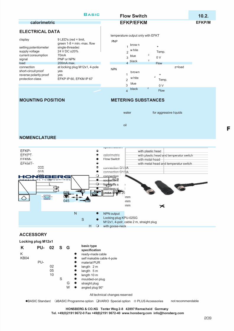
7/22/2019 General Honsberg
http://slidepdf.com/reader/full/general-honsberg 211/347
Flow Switch 10.2.calorimetric EFKP/EFKM EFKP/M
ELECTRICAL DATAtemperature output only with EFKT
display 9 LED's (red = limit,green 1-8 = min.-max. flowsingle-threaded24 V DC ±20%70mAPNP or NPN200mA max.at locking plug M12x1, 4-pole z=loadyesyesEFKP IP 60, EFKM IP 67
MOUNTING POSITION METERING SUBSTANCES
water for aggressive liquids
oil
NOMENCLATUREbasic typespecification
with plastic headwith plastic head and temperatur switchwith metal headwith metal head and temperatur switch
connection G1/4Aconnection G1/2Aconnection footstuffs sensor ISO 2852 size 38socket threadfootstuffs sensor stainless steel 1.4571probe length 29.6mmprobe length 28mmprobe length 45mmprobe length 56mmPNP outputNPN outputLocking plug KPU-02SGM12x1, 4-polr, cable 2 m, straight plugwith goose-neck
ACCESSORY
Locking plug M12x1basic typespecificationready-made cableself makable cable 4-polematerial PURlength 2 mlength 5 mlength 10 mmoulded-on plugstraight plugangled plug 90°
All technical changes reserved
BASIC Standard BASIC Programme option VARIO Special option ⊕ PLUS Accessories not recommendable
calorimetricFlow Switch
H
S
NP
056045028
K 029 P S
EFKM-
EFKP-
EFKMT-
029
038
L
015 H
015
EFKP-
EFKPT-
008
K
H
load
reverse polarity proof protection class
setting potentiometer supply voltagecurrent consumptionsignal
KB04K
PU-02
G
1005
S
connectionshort-circuit proof
K PU- 02 S G
HONSBERG & CO.KG Tenter Weg 2-8 42897 Remscheid GermanyTel. +49(0)2191 9672-0 Fax +49(0)2191 9672-40 www.honsberg.com [email protected]
W
PNP
1
2
3
w hite
blue zTemp.
0 V
+brow n
4 Flowzblack
Flow
0 V
Temp.
+
NPNbrown
w hite
blue
black
1
2z
z3
4
F
Basic
209

7/22/2019 General Honsberg
http://slidepdf.com/reader/full/general-honsberg 212/347
Flow Switch 10.2.calorimetric EFK2 EFK2.
GENERAL CHARACTERISTICS Male thread G1/4A or G1/2A stainless steel
TECHNICAL DATAoperating ranges water 20-50 cm/s (1-150)
oil (on request)standard values shown bold
operating pressure max. 100 bar, option 200 bar foodstuffs sensor 60bar
operating temperature 15..70°C (other temperatureon request)
temperature gradient 4°C/sweight 0.3 kg
MOUNTING
locking plug (accessories)
MATERIALS
medium contact stainless steel 1.4571other stainless steel 1.4305
HONSBERG & CO.KG Tenter Weg 2-8 42897 Remscheid GermanyTel. +49(0)2191 9672-0 Fax +49(0)2191 9672-40 www.honsberg.com [email protected]
“goose-neck” option for higher temperatures
The Flow Switch EFK 2 controls liquid and gaseoussubstances. The instrument combines compactdimensions, an easy switch setting by potentiometer, adual colour LED and a Galvanic insulated switch signal(NO) or transistor outputs (PNP/NPN). As option, aninclineable swan neck is available as a connection of sensor to housing to receive higher temperature ratingsand better reading possibilities.
compact Flow Switchno moving parts in the medium being monitoredmounting largely independent of pipe diameter
If you would like to exploit the highest possible sensor sensitivity (for particularly low flow rates or for use ingases), orientate the cross on hexagonal body of probe(liquids) or the red dot (gases) into a position againstflow direction ( flow meets cross or dot). See also thegeneral description on calorimetric sensors.
210
Basic
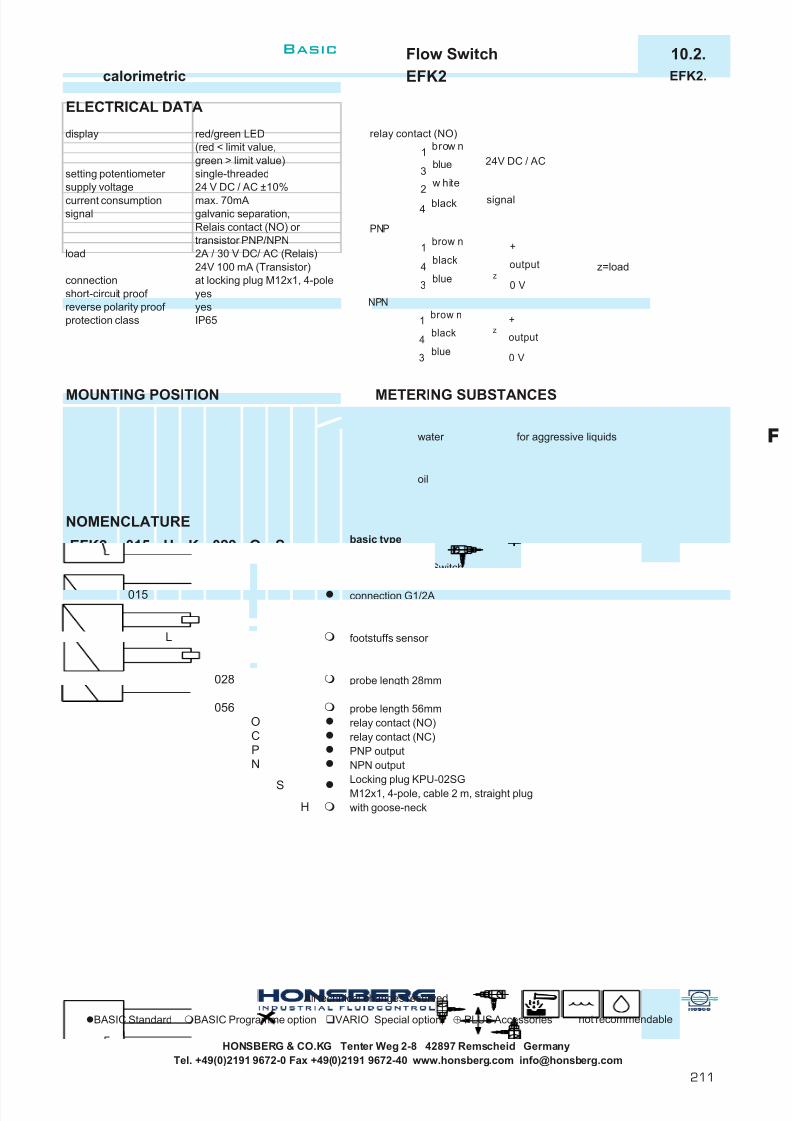
7/22/2019 General Honsberg
http://slidepdf.com/reader/full/general-honsberg 213/347
Flow Switch 10.2.calorimetric EFK2 EFK2.
ELECTRICAL DATA
display red/green LED(red < limit value,green > limit value)single-threaded24 V DC / AC ±10%max. 70mA
signal galvanic separation,Relais contact (NO) or transistor PNP/NPN
load 2A / 30 V DC/ AC (Relais)24V 100 mA (Transistor) z=loadat locking plug M12x1, 4-poleyesyesIP65
MOUNTING POSITION METERING SUBSTANCES
water for aggressive liquids
oil
NOMENCLATUREbasic typespecificationcalorimetric Flow Switchconnection G1/4Aconnection G1/2Aconnection footstuffs sensor ISO 2852 size 38socket threadfootstuffs sensor stainless steel 1.4571probe length 29.6mmprobe length 28mmprobe length 45mmprobe length 56mmrelay contact (NO)relay contact (NC)PNP outputNPN output
Locking plug KPU-02SGM12x1, 4-pole, cable 2 m, straight plugwith goose-neck
All technical changes reserved
BASIC Standard BASIC Programme option VARIO Special option ⊕ PLUS Accessories not recommendable
HONSBERG & CO.KG Tenter Weg 2-8 42897 Remscheid GermanyTel. +49(0)2191 9672-0 Fax +49(0)2191 9672-40 www.honsberg.com [email protected]
029 O
K
N
056045
SH
CO
P
008
028029
SEFK2-
H038015
L
015 H
setting potentiometer
KEFK2-
reverse polarity proof protection class
connection
supply voltagecurrent consumption
short-circuit proof NPN
1
4
3
black
blue
zoutput
0 V
+brow n
PNP
1
4
3
black
blue zoutput
0 V
+brow n
relay contact (NO)
1
3
2
blue
w hite
24V DC / AC
signal
brow n
4 black
Basic
211
F

7/22/2019 General Honsberg
http://slidepdf.com/reader/full/general-honsberg 214/347
Flow and Temperature Sensor 52.2.calorimetric Flex-FIN Flex-FIN
TERMINAL ASSIGNMEN
flow switch/transmitter of low flow ratespossible combination with temperature switch or transmitter no movable parts in monitoring medium MOUNTINGonly a material in contact with mediaeasy uselow pressure losses
different nominal diameter very fast reaction times for a calorimetric systemlinearized and temperature-compensated
BENEFIT
PROGRAMMING
The following output combinations are available:
Designs with a limit switch have a magnetic contact by means of which the current measurement value can be assumed as a limitvalue. It is programmed by applying a magnet to the marking on thetype plate for 0.5 to 2 seconds. If the contact time is too short or toolong, no programming will take place (protection against magneticfields). Immediately after programming, the switching output entersthe OK state (LED on, output switched through, e.g. PNP = high or NPN = low).
The Flex-FIN flow sensor monitors liquid media. In a compactdesign, it combines the installation sensing element and evaluationelectronics that, according to the respective version, control a limitvalue output with a PNP or NPN transistor output or an analogueoutput (4..20 mA or 0..10 V) or both. The limit switch canalternatively be replaced by a frequency output.The evaluation electronics record two processing parameters: theflow speed of the medium and its temperature. Both parameters canbe assigned to the analogue output or the switching output.
The analogue output can be designed as a 4..20 mA output or as a0..10 V output.
The standard design of the switching output is as a limit switch Pushpull (PNP or NPN). It can be ordered as a minimum switch or maximum switch. Alternatively, the switch is available as a frequencyoutput.
For further options, see page 3
Before the electrical installation, make sure that the supply voltagecorresponds to the data provided!
HONSBERG & CO.KG Tenter Weg 2-8 42897 Remscheid GermanyTel. +49(0)2191 9672-0 Fax +49(0)2191 9672-40 www.honsberg.com [email protected]
Please you use shielded cable, signal lines < 30m andpower supply lines < 10m.
flow temperatureanalogue switching output analogue switching output
To maintain the greatest possible interference insensitivity of thesensor, the flow should be from the bottom to the top (best
ventilation even in case of the lowest flow velocity). For theconnection, conventional crimp connectors, hoses with crimpfasteners, or Honsberg's own crimp connectors can be used.For the best possible insulation from the outside environment,insulating hoses that may not be removed can be used.
1
4
3
black
A nalogue Output0 V
+ 24 V DC ±10%brow n
2
Sw itch-/Frequency-Output
w hite
blue
z z
PNP NPN
Z = Last
212
Basic
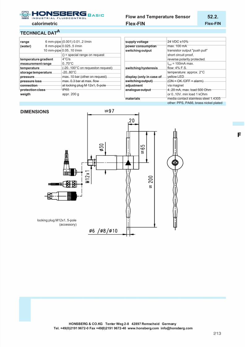
7/22/2019 General Honsberg
http://slidepdf.com/reader/full/general-honsberg 215/347
Flow and Temperature Sensor 52.2.calorimetric Flex-FIN Flex-FIN
TECHNICAL DAT
range 6 mm-pipe (0.001) 0.01..2 l/min supply voltage 24 VDC ±10%(water) 8 mm-pipe 0.025..5 l/min power consumption max. 100 mA
10 mm-pipe 0.05..10 l/min switching output transistor output "push pull"() = special range on request short circuit proof,
temperature gradient 4°C/s reverse polarity protected,measurement range 0..70°C I out = 100mA max.temperature (-20..100°C on requeston request) switching hysteresis flow: 4% F.S.storage temperature -20..80°C temperature: approx. 2°Cpressure max. 10 bar (other on request) display (only in case of yellow LEDpressure loss max. 0.3 bar at max. flow switching output) (ON = OK /OFF = alarm)connection at locking plug M 12x1, 5-pole adjustment via magnet
IP65 4..20 mA, max. load 500 Ohmweigth appr. 200 g or 0..10V. min load 1 kOhm
media contact stainless steel 1.4305other: PPS, PA66, brass nickel plated
DIMENSIONS
HONSBERG & CO.KG Tenter Weg 2-8 42897 Remscheid GermanyTel. +49(0)2191 9672-0 Fax +49(0)2191 9672-40 www.honsberg.com [email protected]
materials
analogue outputprotection class
locking plug M12x1, 5-pole(accessory)
Basic
213
F
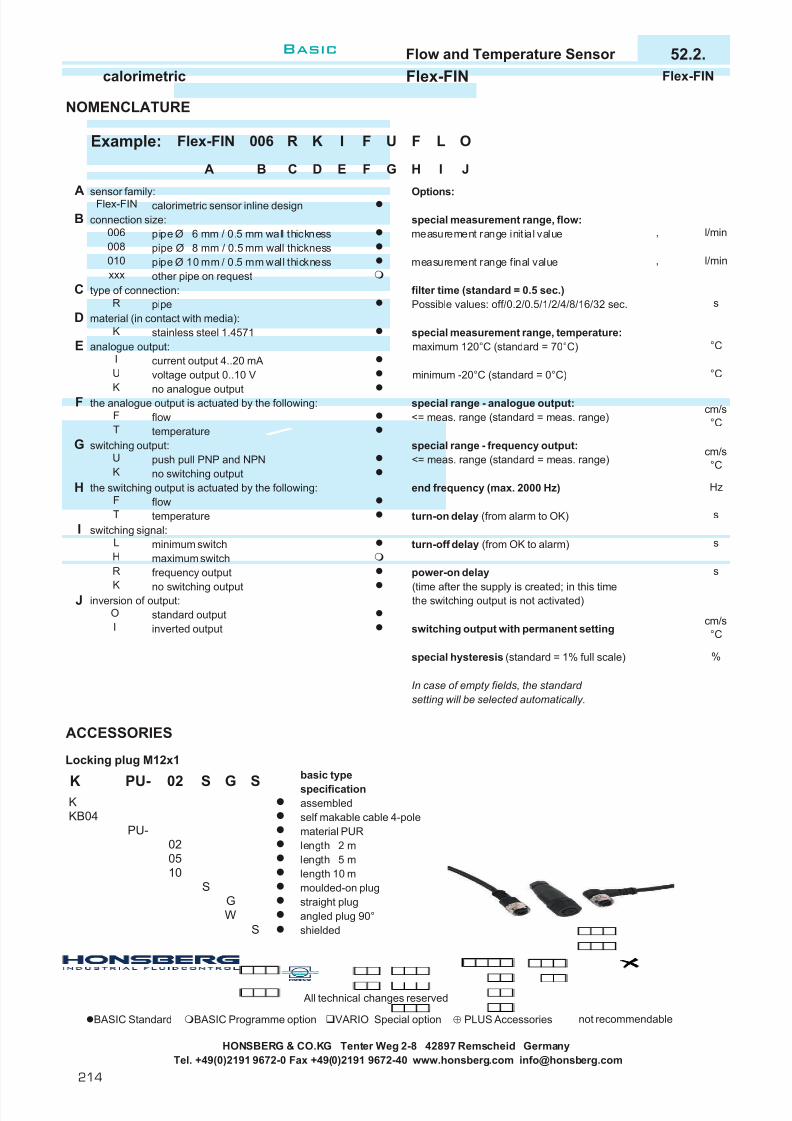
7/22/2019 General Honsberg
http://slidepdf.com/reader/full/general-honsberg 216/347
Flow and Temperature Sensor 52.2.calorimetric Flex-FIN Flex-FIN
NOMENCLATURE
sensor family: Options:calorimetric sensor inline designconnection size: special measurement range, flow:
pipe Ø 6 mm / 0.5 mm wall thickness measurement range initial valuepipe Ø 8 mm / 0.5 mm wall thicknesspipe Ø 10 mm / 0.5 mm wall thickness measurement range final valueother pipe on request
type of connection: filter time (standard = 0.5 sec.)pipe Possible values: off/0.2/0.5/1/2/4/8/16/32 sec.
material (in contact with media):stainless steel 1.4571 special measurement range, temperature:
analogue output: maximum 120°C (standard = 70°C)current output 4..20 mAvoltage output 0..10 V minimum -20°C (standard = 0°C)
no analogue outputthe analogue output is actuated by the following: special range - analogue output:flow <= meas. range (standard = meas. range)temperature
switching output: special range - frequency output:push pull PNP and NPN <= meas. range (standard = meas. range)no switching output
the switching output is actuated by the following: end frequency (max. 2000 Hz)flowtemperature turn-on delay (from alarm to OK)
switching signal:minimum switch turn-off delay (from OK to alarm)maximum switchfrequency output power-on delay
no switching output (time after the supply is created; in this timeinversion of output: the switching output is not activated)
standard outputinverted output switching output with permanent setting
special hysteresis (standard = 1% full scale)
In case of empty fields, the standard setting will be selected automatically.
ACCESSORIES
Locking plug M12x1basic typespecificationassembledself makable cable 4-polematerial PURlength 2 mlength 5 mlength 10 mmoulded-on plugstraight plugangled plug 90°shielded
All technical changes reserved
BASIC Standard BASIC Programme option VARIO Special option ⊕ PLUS Accessories not recommendable
HONSBERG & CO.KG Tenter Weg 2-8 42897 Remscheid GermanyTel. +49(0)2191 9672-0 Fax +49(0)2191 9672-40 www.honsberg.com [email protected]
K
J
L
R
K
O
S
s
G
T
F
H
U
%
I
02PU-
cm/s°C
, l/min
J
G
s
H
Is
Hz
cm/s°C
l/min
cm/s°C
°C
°CE
FF
s
UI
CR
DK
BA
006 R
Flex-FIN
Flex-FIN
CB
xxx
A
006
K
010008
T
05
GW
PU-
10
02
KKKB04
,
F
F G
S
D
I L
IH
U FExample: K O
E
S
S
214
Basic

7/22/2019 General Honsberg
http://slidepdf.com/reader/full/general-honsberg 217/347
Flow Switch 10.2.calorimetric EFKS + EEFK EFKS.
GENERAL CHARACTERISTICS Male thread G1/4A bis G1/2A stainless steel
EFKS
EEFK
TECHNICAL DATAoperating ranges water 20-50 cm/s (1-150) EFKS
oil (on request)standard values shown bold
operating pressure max. 100 bar, option 200 bar foodstuffs sensor 60bar
operating temperature 15..70°C (other temperatureon request)
temperature gradient 4°C/sweight 0.12 kg EFKS
0.35 kg EEFK
MOUNTING
EEFK
MATERIALS
medium contact stainless steel 1.4571other stainless steel 1.4305electronic housing polycarbonate / ABS / makrolon
The EFKS... Flow Switch are compact screw-insubmersible probes which incorporate the temperaturesensors and the heater. They are intended for operationonly with the appropriate EEFK... External EvaluationUnits and are emploied where application of sensors inthe compact range would not be practicable (e.g. noaccess required or possible).The sensors are available with various lengths and threadconnections.
mounting largely independent of pipe diameter no moving parts in the medium being monitoredmounting largely independent of pipe diameter
If you would like to exploit the highest possible sensor sensitivity (for particularly low flow rates or for use ingases), orientate the cross on hexagonal body of probe(liquids) or the red dot (gases) into a position againstflow direction ( flow meets cross or dot). See also thegeneral description on calorimetric sensors.
HONSBERG & CO.KG Tenter Weg 2-8 42897 Remscheid GermanyTel. +49(0)2191 9672-0 Fax +49(0)2191 9672-40 www.honsberg.com [email protected]
Basic
215
F

7/22/2019 General Honsberg
http://slidepdf.com/reader/full/general-honsberg 218/347
Flow Switch 10.2.calorimetric EFKS + EEFK EFKS.
ELEKTRISCHE DATEN
display red/green LED BK= black (yellow) WH= white(red < limit value, BN= brown BU= blue (green)single-threaded (only for DIN colours!) Temp. outputs only with EEFKT24 V DC ±20% / 70mA for unloaded output230 VA / 7 VAPNP or NPN / 200mAadd. change over contacts230V AC 5A (only for 230 VDC types)PNP or NPN / 200mAadd. change over contacts230V AC 5A (only for 230VDC types)floor mounting or clip fastening on mountingrails (DIN EN 50 022)at locking plug M12x1, 4-polescrew terminals
< 1.5mm² withwire-end ferrulesyesyes
protection class IP 67 EFKSIP 30 EEFK front
MOUNTING POSITION METERING SUBSTANCES
water for aggressive liquids
oil
NOMENCLATUREbasic typespecificationcalorimetric Flow Switchconnection G1/4Aconnection G1/2Aconnection footstuffs sensor ISO 2852 size 38socket threadfootstuffs sensor stainless steel 1.4571probe length 29.6mmprobe length 28mmprobe length 45mmprobe length 56mmLocking plug KPU-02SG - M12x1, 4-polr, cable 2 m, straight plug
basic typespecificationexternal evaluation units at calorimetric sensorsexternal evaluation units at calorimetric sensors with temperature switch24 V DC (only PNP or NPN)230 V AC (additional change-over contacts)output PNPoutput NPN
All technical changes reserved
BASIC Standard BASIC Programme option VARIO Special option ⊕ PLUS Accessories not recommendable
signal Temp.temperature (EEFKT)
housing mounting
connection EFKSconnection EEFK
S
wire-core cross-section
short-circuit proof reverse polarity proof
EFKS-
EEFK- 015 H
029
015
KLH
setting potentiometer supply voltage
038
015 H
signal flow
EEFK-
EFKS-008
K
024EEFKT-
029
230PN
045028
056
HONSBERG & CO.KG Tenter Weg 2-8 42897 Remscheid GermanyTel. +49(0)2191 9672-0 Fax +49(0)2191 9672-40 www.honsberg.com [email protected]
S
brown
blue (green)
black (y ellow )
w hite
Sensor EFKS...
externalelectronicsEEFK...
1112
13
14
13
4
2
(only for DIN colours!)
8 7 6 5 4 3 2 1
BN BU BK WH
Sensor
9 10 11 12 13 14 15 16
230 V AC
0VDC +24VDC
OUTFlow
OUTTemp.
Flow Temp.
top
bottom
216
Basic

7/22/2019 General Honsberg
http://slidepdf.com/reader/full/general-honsberg 219/347
Flowmeter 11.1.magnetic inductive FIS FIS.
GENERAL CHARACTERISTICS assembly welded pruning, assembly clamp DN 50-150
TECHNICAL DATA PRINCIPLEmeasuring ranges end range 1 to 8 m/s
in steps of 1 m/saccuracy ±5 % of measured value
(calibration on site + 2 % of measured value
reproducibility ±2 % of measurement valuetime constant 5 second fixedmeasurement lagely homogeneous fluids, U = k . B . v . Dsubstance pastes can also include k = constant for the instrument
solid Particles B = strength of magnetic fieldmedia conductivity min. 20 µS/cm v = local speedflow temperature -25..150°C D =distance between electrodesambient temperature -25..60°Csystem pressure max. 25 bar welded tube
max. 10 bar clamp saddleweight 2.4kg without clamp saddle
Maße ab Außendurchmesser Rohr
FIS-...BB
MATERIALS
probe stainless steel 1.4435isolation ceramic (zirkonium oxide)clamp saddle PP, 1.4305housing stainless steell 1.4305
viton, klingerit 150 160 143
The magnetic-inductive FIS probe is assembled into thepipe by support of a sleeve welded into the relevant pipeto receive the sensor (min.pipe diameter DN 5o). For installation position and depth see diagrams Alternativelya clamp saddle arrangement may be used.
mesurement of conductive liquidsone sensor for a wide range of pipe diametershigh grate materialsno moving partschangeable sensor with no lost of liquid
10090
DN D H50 63 11065 75 11380
125
B7080
90 120100
130140 135 125110 125
HONSBERG & CO.KG Tenter Weg 2-8 42897 Remscheid GermanyTel. +49(0)2191 9672-0 Fax +49(0)2191 9672-40 www.honsberg.com [email protected]
If a conductor moves vertically in relation to a magnetic field, the movementwill induce an electrical potential U in the conductor. In this measuringprinciple the electrically conductive measuring medium is the conductor. Themagnetic field B is produced at right angles to the flow. The induced electricalpotential U is directly proportional to the local speed of flow v.
The potential U is tapped at theelectrodes, midpoint and earth (tube)electrodes, and converted to aproportional 4(0)-20 mA signal.
FIS-025VK
Basic
217
F

7/22/2019 General Honsberg
http://slidepdf.com/reader/full/general-honsberg 220/347
Flowmeter 11.1.magnetic inductive FIS FIS.
MOUNTING
ELECTRICAL DATA
supply voltage 24V DC ± 10%
current consumtion 50mA (bei 24VDC und 20°C)output 4..20mA (passiver Strom-
ausgang) Lastwiderstandmax. 500 W
protection class IP 65 cable gland
IP 67 locking plug
1 DIP switch for end of scale2 Push bottom for zero-adjustment3 Terminal block
Sample : to the DIP switch
1
2 = 3m/s48
separate power connection
FE<10 OhmEarth
same power connectionMust beinstalled!
no error : measurment activity,current output 0(4)-20 mA
error : current output reads 3 mA, error!
HONSBERG & CO.KG Tenter Weg 2-8 42897 Remscheid GermanyTel. +49(0)2191 9672-0 Fax +49(0)2191 9672-40 www.honsberg.com [email protected]
Power supply (24V DC) at the terminals 12 and 11 withmax 1.5mm² Current consumption at 24V DC max 50mA(at 20°C) Current output : 24V DC (terminals 6 (-) and 5(+). Check polarity! Max load 500 Ohm.Zero setting: Fill pipe completely with measuring sub-
stance. Flow speed in the pipeline must be "zero"! Pressbutton marked "ZERO CAL". After a minute, the de-vicewill have self-calibrated.
An automatic self-test will be carried out when the device
Do not unscrew completeley! Rotate the electronics unitas appropriate, then tighten the screws again. Thedirection of the arrow is not asserted to the alignment of the housing.
Output signals are set using the DIP switch(1,2,3,4,5,6,7,8 m/s, see sketch).
To make the electrical connection, open the cover (heldby security band) and remove the 3 hexagonal headscrews inside (take care not to loose the screws!)Thearrow on the electronics unit must point into the directionof the flow release screw (19) 2 turns.
The magnetic-inductive FIS probe is assembled into the pipe by support of a sleeve welded into the relevant pipe to receive the sensor (min.pipe diameter DN 5o). For installation position and depth see diagrams Alternatively a clamp saddle arrangement may be used.Inlet and outlet sections must be >= 10x diameter of pipe. Weld the connector sleeve vertically to the centre of the pipe according to thepipes nominal diameter (see marking = external pipe diameter). Do not use force! The Probe must be screwed in handtight. After putting in place, the probe can be aligned by rotation (see electrical connection). The complete measuring probe is removable withoutdamaging the carrier, so that the electronic part can be exchanged in case of defect.
2
5
3
4
1
24 V DC
12 1156
6 5 12 11
24 V DC
24 V DC
218
Basic

7/22/2019 General Honsberg
http://slidepdf.com/reader/full/general-honsberg 221/347
Flowmeter 11.1.magnetic inductive FIS FIS.
MOUNTING POSITION METERING SUBSTANCES
water for aggressive liquids
measurement of conductive liquids
NOMENCLATURE
basic typespecificationDN 025 (welded tube)DN 050
DN 065DN 080DN 100DN 125DN 150welded tubeclamp saddlestainless steel (welded tube)PP (clamp saddle)1 m/s2 m/s3 m/s4 m/s5 m/s6 m/s7 m/s8 m/scable gland Pg9 (cable not included)connection at locking plugs M12x1, 4-pole
special application smart-FIS
ACCESSORY
Locking plug M12x1
basic typespecificationready-made cableself makable cable 4-polematerial PURlength 2 mlength 5 mlength 10 mmoulded-on plugstraight plugangled plug 90°
counter EEZ904, product information 83.1.EEZ904.
All technical changes reserved
BASIC Standard BASIC Programme option VARIO Special option ⊕ PLUS Accessories not recommendable
HONSBERG & CO.KG Tenter Weg 2-8 42897 Remscheid GermanyTel. +49(0)2191 9672-0 Fax +49(0)2191 9672-40 www.honsberg.com [email protected]
WG
S
05
PU-02
G02 S
S
006005
The positions vertical are not recommended due to air bubbles or sediments in pipe
FIS-
004003
10
K PU-
KB04K
001002
008G
007 e n
d o
f s c a
l e
BK
BV
150125100080065
050
G025
025 V K 001
The FIS transducer is also available with a smart-electronic cover. This electronic includes a display, twoprogrammable switch points, frequency output, progr. filter, linearisation, memory of extrem values, totaliser,choiseable unit on the display.
Basic
219
F

7/22/2019 General Honsberg
http://slidepdf.com/reader/full/general-honsberg 222/347
Flow switch / flowmeter 14.1.vortex Centriflow CF CF.
GENERAL CHARACTERISTICS Female thread G1/4 to G1 1/4 brass/stainless steel/plastic
CF-025GMM135UIS
TECHNICAL DATA
CF-006GM.CF-008GM.CF-010GM.CF-015GM.CF-020GM.
CF-025GM.CF-032GM.
tolerance ±2% of measured valuemedia temperature 5..80°Cstorage temperature -25..80°Ccavitation not with P withdrawal / P difference 5.5average pressure loss 0.1 bar at Qmax.
OPERATION
MATERIALS
housing brass nickel plated, s.s.1.4571 or POM GFconnectors brass nickel plated, s.s.1.4571 or POMdetector ETFE PA6T6I 40%GFseal EPDM
HONSBERG & CO.KG Tenter Weg 2-8 42897 Remscheid GermanyTel. +49(0)2191 9672-0 Fax +49(0)2191 9672-40 www.honsberg.com [email protected]
15305085
38114
96
8.5 - 135 l/min
38
rangel/min H2O
0.6 - 7 l/min1.0 - 15 l/min2.5 - 30 l/min4.5 - 50 l/min6.0 - 85 l/min
38
G 1 1/4114
G 1/216
16
114
G 115 - 240 l/min 11416
G 3/8 16
G 3/4
38100
1638
14.516.5
18.5
16
Type
G 1/8G 1/4
12.5
Lmm
7
G PNbar
1612.512.5
Qmax. recom.l/min H2O
SWmm
Hmm
114 88 38
Xmm
114 88
114 9288
135240 108 46
A narrow, triangular body (1) that goes through the entirecross-section of the meter tube creates a vortex when aflow is present (Kármán's vortex effect). The frequency of the vortex is proportional to flow and is detected by apiezo sensor (2) lying behind the triangular body. Theentire unit, vortex body, and detector as designed as amodule (3). They are inserted into the tube. The meter tube and the entire measuring unit can thus be separatedfrom each other extremely quickly.
high accuracylarge overload securityno moving partsfast installation and removal by clamp attachmentmodular construction with the most versatileconnection systems
The vortex flowmeter requires a feed distance of 5 - 10xDto achieve its nominal precision. If deposits are feared, thesensor should not be installed with the electronics pointing
downward. Please observe that the sensor is installed inthe direction of the flow arrow. For possible cleaning of thesensor, loosen the clamps and remove the device (in theprocess, the line should be depressurized. Make surethat the vortex does not expose the oscillating body toimpacts (the spraying unit contains a very sensitiveceramic piezo transducer that can break).
22.5
11 2
3
flow
220
Basic

7/22/2019 General Honsberg
http://slidepdf.com/reader/full/general-honsberg 223/347
Flow switch / flowmeter 14.1.vortex Centriflow CF CF.
ELECTRICAL DATsupply voltage 10..30 V DC idle current 100 mAconnection for locking plug M12x1, 4-pole output current 4..20 mAshort-circuit proff yes voltage 0..10Vreverse polarity proff yes frequency output / programmable switchprotection class IP 67 idle current < 20 mA (without load)
output PNP and NPN10..2000 Hz
MOUNTING POSITION METERING SUBSTANCES
water
oil
NOMENCLATUREFor combinations see table "technical data".
basic typespecificationnominal diameter DN 006nominal diameter DN 008nominal diameter DN 010nominal diameter DN 015nominal diameter DN 020nominal diameter DN 025nominal diameter DN 032female threadmale threadnozzleconnection material brass Ms 58 nickel plated
connection material stainless steel 1.4571connection material POMhousing material brass Ms 58 nickel platedhousing material stainless steel 1.4571housing material POMrange 0.6 - 7 l/minrange 1.0 - 15 l/minrange 2.5 - 30 l/minrange 4.5 - 50 l/minrange 6.0 - 85 l/minrange 8.5 - 135 l/minrange 15 - 240 l/minseal EPDMseal Viton
seal NBRvoltage output 0..10Vcurrent output 4..20mAfrequency outputprogrammable switch (push pull PNP and NPN)ouput at suburb electronics (e.g. omni-CF)connection at locking plugs M12x1, 4-pole
COMBINATIONSomni-CF Flex-CFlocal electronic unit, switching and frequency exit2xNPN and PNP switch 0..10V or 4..20mA4(0)..20mA output pnp, npngraphical LCD display with flashing LED
program ring All technical changes reserved
BASIC Standard BASIC Programme option VARIO Special option ⊕ PLUS Accessories not recommendable
HONSBERG & CO.KG Tenter Weg 2-8 42897 Remscheid GermanyTel. +49(0)2191 9672-0 Fax +49(0)2191 9672-40 www.honsberg.com [email protected]
006008
U S
current - / voltage output
CF- 006 G M M 007 E
G A
010015020025032
T
K
M
PM
PK
015007
030050085
240135
VE
NUIF
ES
S
At a viscosity of >1mm²/s (water), theresponse threshold rises since the vortexforms at a higher flow speed.
PNP / current- / v oltage output
1
4
3
black
blue zoutput
0 V
+brow n
2 programmingw hite
NPN
1
4
3
black
blue
zoutput
0 V
+brow n
2 programmingw hite
Basic
221
F

7/22/2019 General Honsberg
http://slidepdf.com/reader/full/general-honsberg 224/347
Market segments
Where to use aelectronic flow instrument
Application
l Machine tools
l Sewage
l Semi conductorindustry
l Welding
l Low pressurecleaners
l Flow rate monitoring and display in wafer productionl Flow rate alarm in control panels of robot weldersl Pump command in cleaning installations
Honsberg & Co. KGTenter Weg 2-8 · 42897 Remscheid · GermanyP.O. Box 1103 69 · 42863 Remscheid · GermanyTel. +49(0)2191 9672-0 · Fax +49(0)2191 9672-40www.honsberg.com · [email protected]
222
Basic

7/22/2019 General Honsberg
http://slidepdf.com/reader/full/general-honsberg 225/347
223
Sight glass, flap, sphere
Sight glassThe liquid medium enters the sight glass and can thus be checked opticallyfor quality and consistency.
FlapThe liquid medium enters the sight glassand can thus be checked optically forquality and consistency. Quantitativeindication of the flow rate is possibledepending on the flap’s position in theglass.
SphereThe liquid medium enters the sight glassand can thus be checked optically forquality and consistency. Quantitativeindication of the flow rate is possibledepending on the sphere’s position in
the glass.
Contents
System description 224
Device descriptions 225
l Indicating
Concept Housing with window or tubeNominal diameter 8 - 50Connection female threadPN 6 - 16Max. temperature 200 °CSignal –Adjustable –Materials brass, stainless steelInstallation position any or definedMetering materials liquids and gases
Technical data
The technology
Application
l Visual flow monitoring of liquids
Advantages
l Simple structurel Double-faced viewing fieldl Reliable function
G

7/22/2019 General Honsberg
http://slidepdf.com/reader/full/general-honsberg 226/347
Honsberg & Co. KGTenter Weg 2-8 · 42897 Remscheid · GermanyP.O. Box 1103 69 · 42863 Remscheid · GermanyTel. +49(0)2191 9672-0 · Fax +49(0)2191 9672-40www.honsberg.com · [email protected]
Basic
224
System description
Device systemsSight glassThe medium enters the device body and is usually visible through double-faced glass windows.
Function: sight glass onlyApplication: monitoring dark or coloured metering materials
FlapThe medium moves a flap built into the medium space. The position of
the flap is an indication of flow rate.
Function: quantitative indicationApplication: monitoring transparent, clean liquids
Flap indicates the position in the sight glass
SphereThe position of the sphere in the glass dome indicates intensity of flow.It may be used for liquids and gases.
Function: yes/no displayApplication: monitoring transparent liquids or gases
By its position in the sight glass the sphere showsa quantitative trend of flow rate.
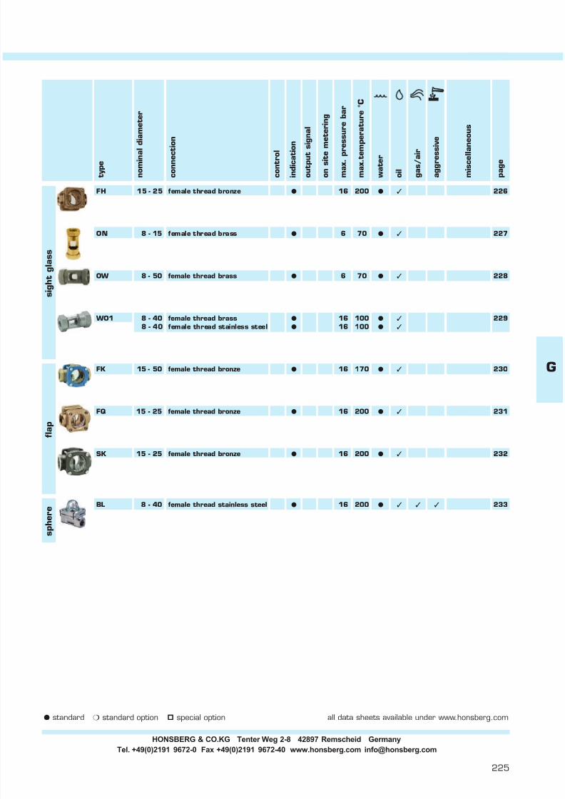
7/22/2019 General Honsberg
http://slidepdf.com/reader/full/general-honsberg 227/347
225
m i s c e
l l a n e o u s
p a g e
a g g r e s s
i v e
g a s
/ a
i r
o i l
i n d i c a t i o n
t y p e
c o n t r o
l
c o n n e c t i o n
o u t p u t s i g n a
l
o n s
i t e m e t e r i n g
m a x . p r e s s u r e
b a r
m a x . t e m p e r a t u r e
° C
w a t e r
n o m
i n a
l d i a m e t e r
FH 15 - 25 female thread bronze l 16 200 l 3 226
ON 8 - 15 female thread brass l 6 70 l 3 227
OW 8 - 50 female thread brassl
6 70l 3
228
WO1 8 - 40 female thread brass l 16 100 l 3 2298 - 40 female thread stainless steel l 16 100 l 3
FK 15 - 50 female thread bronze l 16 170 l 3 230
FQ 15 - 25 female thread bronze l 16 200 l 3 231
SK 15 - 25 female thread bronze l 16 200 l 3 232
BL 8 - 40 female thread stainless steel l 16 200 l 3 3 3 233
f l a p
s p
h e r e
s i g h t g
l a s s
G
l standard m standard option special option all data sheets available under www.honsberg.com
HONSBERG & CO.KG Tenter Weg 2-8 42897 Remscheid GermanyTel. +49(0)2191 9672-0 Fax +49(0)2191 9672-40 www.honsberg.com [email protected]

7/22/2019 General Honsberg
http://slidepdf.com/reader/full/general-honsberg 228/347
Flow Indicator 7.1.sight glass Visoflow FH-...GR FH.
GENERAL CHARACTERISTICS Female thread G1/2 to G1 bronze
FH-015GRTECHNICAL DATA
media temperature water max. 100°Coil max. 200°C
average pressue loss 0.06bar at Qmax.
MATERIALS
body bronze Rg5ring brass Ms58window soda-lime glassseal klingersil C4400
MOUNTING POSITION NOMENCLATUREbasic typespecificationnominal diameter DN 15 - G1/2nominal diameter DN 20 - G3/4nominal diameter DN 25 - G1female thread
bronze
METERING SUBSTANCES
water
oil
All technical changes reserved
BASIC Standard BASIC Programme option VARIO Special option ⊕ PLUS Accessories not recommendable
weightkg
1616FH-025GR
Xmm
251.10
74
1.20141416 1.25
383842
Qmax. recom.l/min H 2O
020
FH-
4565
FH-015GR 16
RG
G
015
R
68
025
015
PNbar
Lmm
858595
Bmm
68
Mechanical Flow Indicator as sight glass for contaminatedor coloured substances. Rugged design in brass / bronzecombination.
no moving partsoptional installationoptical control of liquid qualityfor contaminated or coloured liquidsdouble-faced, wide windowsnatural glass
AFmm
FH-020GR b r o n z e G 1/2
G 3/4G 1
G Type
HONSBERG & CO.KG Tenter Weg 2-8 42897 Remscheid GermanyTel. +49(0)2191 9672-0 Fax +49(0)2191 9672-40 www.honsberg.com [email protected]
Basic
226
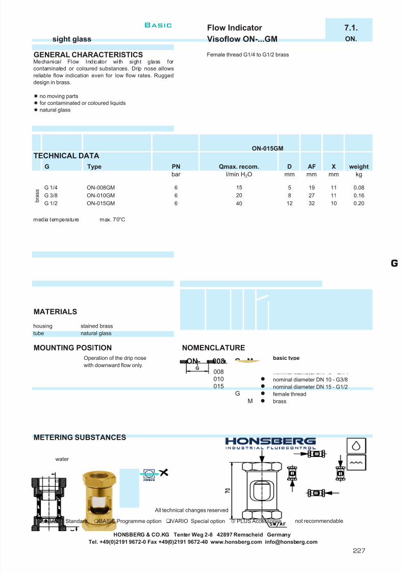
7/22/2019 General Honsberg
http://slidepdf.com/reader/full/general-honsberg 229/347
Flow Indicator 7.1.sight glass Visoflow ON-...GM ON.
GENERAL CHARACTERISTICS Female thread G1/4 to G1/2 brass
ON-015GMTECHNICAL DATA
media temperature max. 70°C
MATERIALS
housing stained brasstube natural glass
MOUNTING POSITION NOMENCLATUREOperation of the drip nose basic typewith downward flow only. specification
nominal diameter DN 8 - G1/4nominal diameter DN 10 - G3/8nominal diameter DN 15 - G1/2female thread
brass
METERING SUBSTANCES
water
oil
All technical changes reserved
BASIC Standard BASIC Programme option VARIO Special option ⊕ PLUS Accessories not recommendable
HONSBERG & CO.KG Tenter Weg 2-8 42897 Remscheid GermanyTel. +49(0)2191 9672-0 Fax +49(0)2191 9672-40 www.honsberg.com [email protected]
0.1611812
M
Xmm
11
Type AFmm
19
G
15
M
G
0.2032
008
4066
weightkg
Dmm
Qmax. recom.l/min H 2O
102720
0.085
G 1/2
008ON-
G
G 1/4G 3/8
PNbar
6ON-008GMON-010GM
Mechanical Flow Indicator with sight glass for contaminated or coloured substances. Drip nose allowsreliable flow indication even for low flow rates. Ruggeddesign in brass.
no moving partsfor contaminated or coloured liquidsnatural glass
ON-015GM b r a s s
015010
G
Basic
227
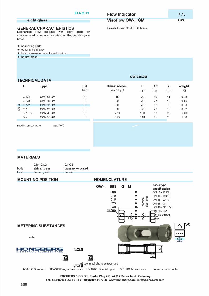
7/22/2019 General Honsberg
http://slidepdf.com/reader/full/general-honsberg 230/347
Flow Indicator 7.1.sight glass Visoflow OW-...GM OW.
GENERAL CHARACTERISTICS Female thread G1/4 to G2 brass
OW-025GMTECHNICAL DATA
media temperature max. 70°C
MATERIALS
G1/4-G1/2 G1-G2body stained brass brass nickel platedtube natural glass acrylic
MOUNTING POSITION NOMENCLATUREbasic typespecificationDN 8 - G1/4DN 10 - G3/8DN 15 - G1/2DN 25 - G1
DN 40 - G1 1/2DN 50 - G2female threadbrass
METERING SUBSTANCES
water
oil
All technical changes reserved
BASIC Standard BASIC Programme option VARIO Special option ⊕ PLUS Accessories not recommendable
HONSBERG & CO.KG Tenter Weg 2-8 42897 Remscheid GermanyTel. +49(0)2191 9672-0 Fax +49(0)2191 9672-40 www.honsberg.com [email protected]
Mechanical Flow Indicator with sight glass for contaminated or coloured substances. Rugged design inbrass.
no moving partsoptional installationfor contaminated or coloured liquidsnatural glass
PNbar
66
OW-008GMOW-010GMG 3/8
G Type
2325
weightkg
0.080.160.200.621.401.50
Xmm
11109
AFmm
192732
Lmm
7070
Qmax. recom.l/min H 2O
1520
130148
6065
n o m i n a l
d i a m e t e r
220
010015
6
G 1/2 6
M
250
008
040
025
193090G 1 OW-025GM
OW-015GM 7090 466
MG
G 1/4
b r a s s
G 1 1/2 OW-040GMG 2 OW-050GM
050
6
008
GOW-
Basic
228

7/22/2019 General Honsberg
http://slidepdf.com/reader/full/general-honsberg 231/347
Flow Indicator 7.1.sight glass Visoflow WO1-…GM/GK WO1.
GENERAL CHARACTERISTICS Female thread G1/4 to G1 1/2 brass/stainless steel
media temperature max. 100°C
MATERIALS
WO1-...GM WO1-...GKhousing brass Ms58 nickel plated stainless steel 1.4305tube duran glass duran glasswipers NBR vitonseal NBR viton
MOUNTING POSITION NOMENCLATUREbasic typespecificationDN 8 - G1/4DN 10 - G3/8DN 15 - G1/2DN 20 - G3/4DN 25 - G1
DN 32 - G1 1/4DN 40 - G1 1/2female threadbrass design
METERING SUBSTANCES stainless steel designPro gramme option seal / wiper EPDMBASIC
water
oil
All technical changes reserved
BASIC Standard BASIC Programme option VARIO Special option ⊕ PLUS Accessories not recommendable
Tel. +49(0)2191 9672-0 Fax +49(0)2191 9672-40 www.honsberg.com [email protected]
weightkg
Xmm
SWmm
0.3936
WO1-025G. 16 90
0.60.6
10494
1346
651646
46 16
Mechanical Flow Indicator with sight glass for contaminated or coloured substances. Rugged design inbrass or stainless steel.
optional installationtube-shaped sight glass withinternal cleaning wipersfor contaminated or coloured liquids360° visibility
60
7186
G 3/8 WO1-010G. 16 20
Lmm
710.3936
0.6
1.61.6
WO1-040G. 16 220 20120130 65
19
WO1- 008
16
M008
G
G 1/2 WO1-015G. 16 30G 3/4
G 1 1/2
G 1G 1 1/4 WO1-032G. 16 150
WO1-020G.
020015
025
n o m i n a l d i a m e t e r
010
040032
MK
G Type PNbar
Qmax. recom.l/min H 2O
G 1/4 WO1-008G. 16 15
G
HONSBERG & CO.KG Tenter Weg 2-8 42897 Remscheid Germany
WO1-010GMTECHNICAL DATA
G
Basic
229

7/22/2019 General Honsberg
http://slidepdf.com/reader/full/general-honsberg 232/347
Flow Indicator 8.1.flap Visoflow FK-...GR FK.
GENERAL CHARACTERISTICS Female thread G1/2 to G2 bronze/cast iron
FK-020GRTECHNICAL DATA
media temperature water max. 100°Coil max. 170°C
average pressure loss 0.06bar at Qmax.
MATERIALSbody bronze / cast iron
cover cast ironwindow hard glassseal flexicarb with metal enforcementbody stainless steel 1.4436flap polysulfon
MOUNTING POSITION NOMENCLATUREbasic typespecificationDN 15 - G1/2DN 20 - G3/4DN 25 - G1DN 40 - G1 1/2DN 50 - G2female threadbronze/cast iron
METERING SUBSTANCES
water
oil
All technical changes reserved
BASIC Standard BASIC Programme option VARIO Special option ⊕ PLUS Accessories not recommendable
HONSBERG & CO.KG Tenter Weg 2-8 42897 Remscheid GermanyTel. +49(0)2191 9672-0 Fax +49(0)2191 9672-40 www.honsberg.com [email protected]
Mechanical Flow Indicator for liquids. A finger flaparranged in the flow chamber provides indication of themomentary flow rate. The partition into three finger elements makes a dynamic indication possible, as eachlight-weight finger-component reacts to the slightestchange of flow characteristic. Rugged design in bronze or cast iron.
double-faced wide windownatural glass
b r o n z e / c a s t i r o n
025
015
170
Type
FK-015GRFK-020GRFK-025GR
0.80G 1
401.6016 60
90
3.00
020015
0.85
G PNbar
weightkg
16
Qmax. recom.l/min H 2O
25
Lmm
90
Dmm
G 1/2
G 1 1/2G 2
1616
FK-040GRFK-050GR
G 3/4
G
FK- G
120250
16
5.90
R
114
R
050040 n
o m i n a l
d i a m e t e r
40
Bmm
74
130
Amm
60607690
110116138
9574
6080
Xmm
1414182025
4049
6174
AFmm
363643
Basic
230

7/22/2019 General Honsberg
http://slidepdf.com/reader/full/general-honsberg 233/347
Flow Indicator 8.1.flap Visoflow FQ-...GR FQ.
GENERAL CHARACTERISTICS Female thread G1/2 bis G1 bronze
TECHNICAL DATA FQ-015GR017
Scale increments 1 to 10. Calibration see nomenclature.
media temperature water max. 100°Coil max. 200°C
average pressure loss 0.09bar at Qmax.
MATERIALS
body bronzering brass
window soda-lime-glassseal klingersil C4400bolt stainless steel 1.4305flap stainless steel 1.4310scale stainless steel 1.4310
MOUNTING POSITION NOMENCLATUREbasic typespecificationnominal diameter DN 15 - G1/2nominal diameter DN 20 - G3/4nominal diameter DN 25 - G1female threadbronzeindication range 2.1- 17 l/min H 2Oindication range 2.1- 20 l/min H 2Oindication range 2.1- 24 l/min H 2O
METERING SUBSTANCES
water
All technical changes reserved
BASIC Standard BASIC Programme option VARIO Special option ⊕ PLUS Accessories not recommendable
HONSBERG & CO.KG Tenter Weg 2-8 42897 Remscheid GermanyTel. +49(0)2191 9672-0 Fax +49(0)2191 9672-40 www.honsberg.com [email protected]
Scale increments 1 to 10. Indication value is indicated for horizontally increasing flow.
14.0 17.8 247.0 7.8 9.2 11.12,1- 24 2.1 4.0 5.0
Mecanical Flow Indicator for liquids. A solid stainless steelflap arranged in the wetted chamber is lifted by theincoming flow and indicates the actual flow rate on anexternal reading scale. Rugged design in bronze/brasscombination.
high temperature dutydouble-faced wide windownatural glass
indication rangel/min H 2O
scale increments
2.1 7.5 8.92.1 3.2 3.8 4.3 4.7 5.0
11.6 206.33.2 4.5 5.2 5.6
10
5.7 9.5 17
7 8 9
7.5
2 3 4 5
8525
6
2.1 - 17 68
025
FQ-015GR017
G PNbar
b r o n z e G 1/2
G 3/4G 1 FQ-025GR024
FQ-020GR0201436
74
020
16
1616
weightkg
Type Qmax. recom .l/min H 2O
Lmm
Bmm
Xmm
AFmm
indication rangel/min H 2O
1.201.10
015
017G R
85
G
1.2568 1436
1642
015
952.1 - 202.1 - 24
4565
FQ-
2,1- 17
R
020017
2,1- 20
1
For combinations see table"technical data".
oil
024
G
Basic
231

7/22/2019 General Honsberg
http://slidepdf.com/reader/full/general-honsberg 234/347
Flow Indicator 8.1.flap Visoflow SK-...GR SK.GR
GENERAL CHARACTERISTICS Female thread G1/2 to G2 bronze/cast iron
TECHNICAL DATA
Scale increments 1 - 10. Calibration see nomenclature.
media temperature water max. 100°Coil max. 170°C
average pressure loss 0.07bar of full scale.
MATERIALSbody bronze / cast ironcover cast ironwindow crown hard glassseal flexicarb with metal enforcementbolt stainless steel 1.4436
flap stainless steel 1.4436scale aluminium
MOUNTING POSITION NOMENCLATUREbasic typespecificationDN 15 - G1/2DN 20 - G3/4DN 25 - G1DN 40 - G1 1/2DN 50 - G2
female threadbronzeindicating range 3 - 25 l/min H 2O
indicating range 5 - 40 l/min H 2OMETERING SUBSTANCES indicating range 10 - 76 l/min H 2O
indicating range 15 - 195 l/min H 2OSpecial option stainless steel design
water VARIO flange connector in cast ironflange connector in stainless steel
Scale increments 1 to 10. Indication value is indicated for horizontally increasing flow.oil
All technical changes reserved
BASIC Standard BASIC Programme option VARIO Special option ⊕ PLUS Accessories not recommendable
15- 195
Qmax. recom .l/min H 2O
30
250
60
076
Mechanical Flow Indicator for liquids. A solid stainlesssteel flap arranged in the wetted chamber is lifted by theincoming flow and indicates the actual flow rate on aninternal reading scale. Rugged design in bronze/cast ironcombination.
high temperature dutydouble-faced wide windowdirt-resistant
5- 4010- 76
Type indicating rangel/min H 2O
3 - 253 - 25
SK-015GR025SK-020GR025
SK-050GR195
5 - 40
10 - 7615 -195
SK-025GR040
SK-040GR076
G
G 1/2G 3/4
b r o n z e / c a s t i r o n
G 1
195
scale increments
7615 23 29 35 41 46 59 79 118
21 2810
36 44 63
255 7 9 10 40
2013 15 18
6
10 14 19
8 9
22 27 30
10
3 4 5 7
71 2
14
8
130
025R
040
543
195
G
040050
SK- 015
020
43
025
R
Amm
90
1.01.01.8
40 143649 18
20 3.4
weightkg
025
Lmm
9090
110
114
95
120
9
806174
For combinations see table"technical data".
605.925
Xmm
AFmm
40 14366040
Dmm
n o m i n a l
d i a m e t e r
116
7460
138
Bmm
16
1616
PNbar
1616
76
170
74
SK-020GR025
3- 25
G 1 1/2G 2
indicating rangel/min H 2O
015
G
HONSBERG & CO.KG Tenter Weg 2-8 42897 Remscheid GermanyTel. +49(0)2191 9672-0 Fax +49(0)2191 9672-40 www.honsberg.com [email protected]
Basic
232

7/22/2019 General Honsberg
http://slidepdf.com/reader/full/general-honsberg 235/347
Flow Indicator 9.1.sphere Visoflow BL-...GK BL.
GENERAL CHARACTERISITICS Female thread G1/4 to G1 1/2 stainless steel
TECHNICAL DATA BL-010GK
media temperature max. 200°Caverage pressue loss 0.2bar at Qmax.
MATERIALS
housing stainless steel 1.4436, 1.4410sphere PTFEdome borosilikateseal viton and klingersil C4400
MOUNTING POSITION NOMENCLATUREbasic typespecificationDN 8 - G1/4DN 10 - G3/8DN 15 - G1/2DN 20 - G3/4
DN 25 - G1DN 40 - G1 1/2female threadstainless steel
METERING SUBSTANCES
water gas/air
aggressiveoil liquids
All technical changes reserved
BASIC Standard BASIC Programme option VARIO Special option ⊕ PLUS Accessories not recommendable
HONSBERG & CO.KG Tenter Weg 2-8 42897 Remscheid GermanyTel. +49(0)2191 9672-0 Fax +49(0)2191 9672-40 www.honsberg.com [email protected]
Amm
Hmm
Lmm
Qmax.recom .
l/min H 2O
weightkg
Xmm
AFmm
Bmm
010
Mechanical Flow Indicator for liquids, gasses or aggressive metering substances. The liquid enters a valvehousing and lifts the ball from the valve seat placed inglass dome. Rugged design in stainless steel.
high temperature duty
BL-040GK s t a i n l e s s s t e e l
G 1 1/2
015
G
020
025
2.5
n o m i n a l
d i a m e t e r
3062
BL-015GK8
12G 1/2G 3/4 7889BL-020GK 25G 1
60BL-025GK
11811 2316 408
0.860
76
122876 67
42 0.760 1628
7760
184267
42
16 1.5
4
6776
89
008
42
50954278 1.3
146060
4545
K
281.4
18
0.7
040
KG
Not recommendable for dark or contaminated liquids.
16
16
G Type
BL-008GK
BL-010GK
G 1/4
G 3/8
PNbar
16
5
BL- 008
164
sphere l/min H 2O
fistmovement
fullvisibility
0.3 1.5
0.3 1.50.32.5
G
Basic
233
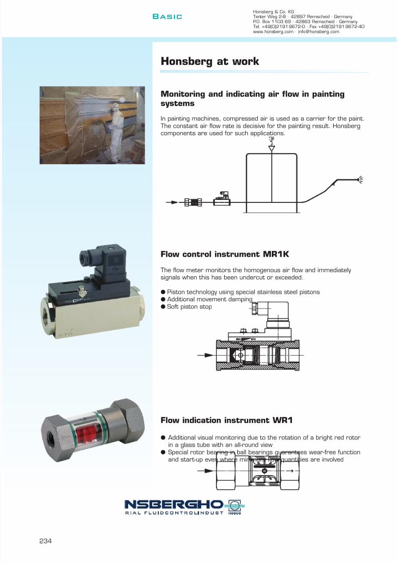
7/22/2019 General Honsberg
http://slidepdf.com/reader/full/general-honsberg 236/347
Honsberg & Co. KGTenter Weg 2-8 · 42897 Remscheid · GermanyP.O. Box 1103 69 · 42863 Remscheid · GermanyTel. +49(0)2191 9672-0 · Fax +49(0)2191 9672-40www.honsberg.com · [email protected]
Basic
234
Honsberg at work
Monitoring and indicating air flow in paintingsystems
In painting machines, compressed air is used as a carrier for the paint.The constant air flow rate is decisive for the painting result. Honsbergcomponents are used for such applications.
Flow control instrument MR1K
The flow meter monitors the homogenous air flow and immediatelysignals when this has been undercut or exceeded.
l Piston technology using special stainless steel pistonsl Additional movement dampingl Soft piston stop
Flow indication instrument WR1
l Additional visual monitoring due to the rotation of a bright red rotorin a glass tube with an all-round view
l Special rotor bearing in ball bearings guarantees wear-free functionand start-up even where minimum flow quantities are involved

7/22/2019 General Honsberg
http://slidepdf.com/reader/full/general-honsberg 237/347
235
Orifice
The technology
The dynamic orifice adapts the size of the cross-section on the basis of flow-dependent differential pressure, thuslimiting the flow rate to a defined
value.
Application
l Independent limitation of flow quantities without external power, forexample during distribution of central feed among consumers.
Advantages
l Can be installed in any positionl No power required Contents
System description 236
Device descriptions 237
l Regulatingl Switching
Concept Metal or elastomer orifice in the housingNominal diameter 10 - 25Connection female threadPN 100 - 200Max. temperature 300 °CSignal thresholdAdjustable –Materials brass, stainless steelInstallation position anyMetering materials liquids
Technical data
H
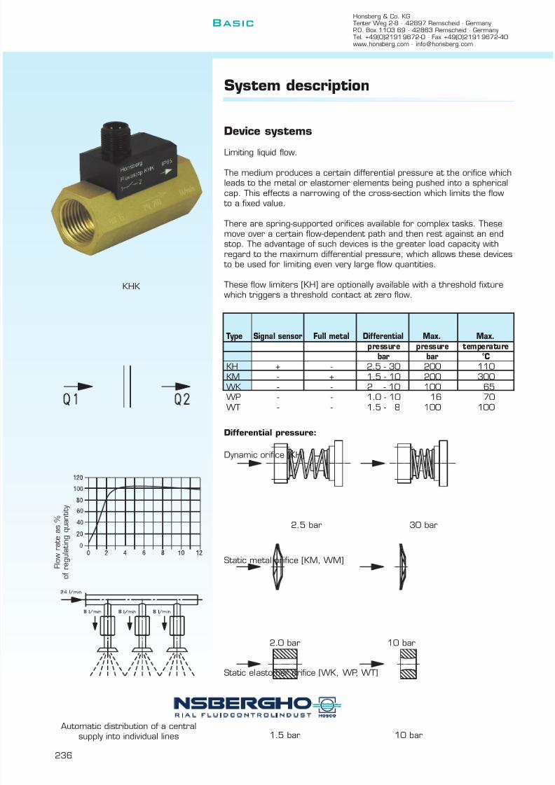
7/22/2019 General Honsberg
http://slidepdf.com/reader/full/general-honsberg 238/347
Honsberg & Co. KGTenter Weg 2-8 · 42897 Remscheid · GermanyP.O. Box 1103 69 · 42863 Remscheid · GermanyTel. +49(0)2191 9672-0 · Fax +49(0)2191 9672-40www.honsberg.com · [email protected]
Basic
236
System description
Device systemsLimiting liquid flow.
The medium produces a certain differential pressure at the orifice whichleads to the metal or elastomer elements being pushed into a sphericalcap. This effects a narrowing of the cross-section which limits the flow
to a fixed value.
There are spring-supported orifices available for complex tasks. Thesemove over a certain flow-dependent path and then rest against an endstop. The advantage of such devices is the greater load capacity withregard to the maximum differential pressure, which allows these devices
to be used for limiting even very large flow quantities.
These flow limiters [KH] are optionally available with a threshold fixturewhich triggers a threshold contact at zero flow.
Type Signal sensor Full metal Differential Max. Max.pressure pressure temperature
bar bar °CKH + - 2.5 - 30 200 110KM - + 1.5 - 10 200 300WK - - 2 - 10 100 65WP - - 1.0 - 10 16 70WT - - 1.5 - 8 100 100
Differential pressure:
Dynamic orifice [KH]
Static metal orifice [KM, WM]
1.5 bar 10 bar
2.5 bar 30 bar
Static elastomer orifice [WK, WP, WT]
2.0 bar 10 bar
Automatic distribution of a centralsupply into individual lines
F l o w r a t e a s
%
o f r e g u l a t i n g q u a n t i t y
KHK

7/22/2019 General Honsberg
http://slidepdf.com/reader/full/general-honsberg 239/347
237
m i s c e
l l a n e o u s
p a g e
a g g r e s s
i v e
a i r / g a s
o i l
i n d i c a t i o n
t y p e
c o n t r o
l
c o n n e c t i o n
o u t p u t s i g n a
l
o n s
i t e m e t e r i n g
m a x . p r e s s u r e
b a r
m a x . t e m p e r a t u r e
° C
w a t e r
n o m
i n a
l d i a m e t e r
l standard m standard option special option current data sheets can be found under www.honsberg.com
Honsberg at work
Independent limitation of cooling systems in X-ray tubesand nuclear magnetic resonance tomographs
X-ray tubes and nuclear magnetic resonance tomographs require precisecooling systems to prevent the tubes from overheating.
Honsberg limiters guarantee independent limitation of the coolant quantity to the required flow rate in the cooling units on the basis of differential pressure,both in the main pipe and in the bypass.
Type KHK limitation in the main flowand additional threshold for interrup-
ting the liquid flow.
Type KH for limitation within thebypass.
KH 15 female thread brass l 200 120 l 23815 female thread stainless steel l 200 120 l
KM 15 - 20 female thread brass 200 300 l l 239
15 - 20 female thread stainless steel 200 300 l l
WK 15 - 25 female thread brass 100 65 l 24015 - 25 female thread stainless steel 100 65 l
WP 15 female thread brass 16 70 l 241
WT 15 female thread brass 100 100 l 242
m e t a
l
e l a s t o m e r e r e
H
HONSBERG & CO.KG Tenter Weg 2-8 42897 Remscheid GermanyTel. +49(0)2191 9672-0 Fax +49(0)2191 9672-40 www.honsberg.com [email protected]
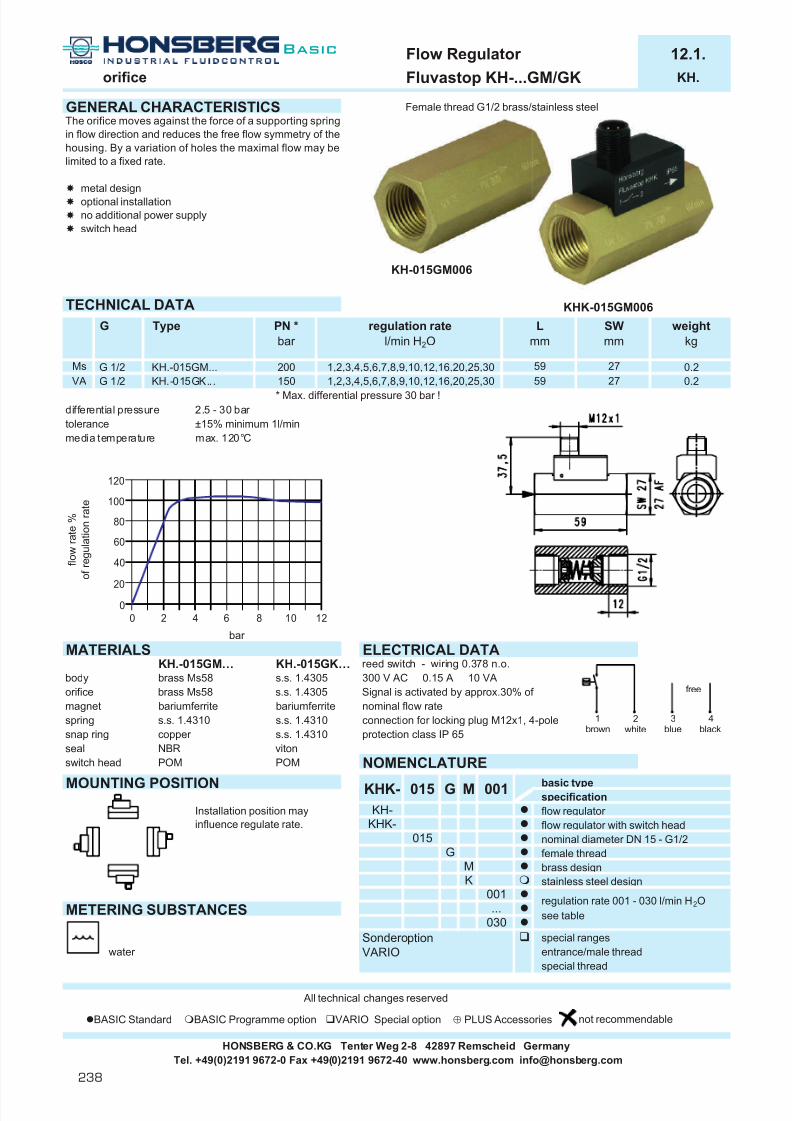
7/22/2019 General Honsberg
http://slidepdf.com/reader/full/general-honsberg 240/347
Flow Regulator 12.1.orifice Fluvastop KH-...GM/GK KH.
GENERAL CHARACTERISTICS Female thread G1/2 brass/stainless steel
TECHNICAL DATA
* Max. differential pressure 30 bar !differential pressure 2.5 - 30 bar tolerance ±15% minimum 1l/minmedia temperature max. 120°C
MATERIALS ELECTRICAL DATAKH.-015GM… KH.-015GK… reed switch - wiring 0.378 n.o.
body brass Ms58 s.s. 1.4305 300 V AC 0.15 A 10 VAorifice brass Ms58 s.s. 1.4305 Signal is activated by approx.30% of magnet bariumferrite bariumferrite nominal flow ratespring s.s. 1.4310 s.s. 1.4310 connection for locking plug M12x1, 4-polesnap ring copper s.s. 1.4310 protection class IP 65seal NBR vitonswitch head POM POM NOMENCLATURE
MOUNTING POSITION basic typespecificationflow regulator flow regulator with switch headnominal diameter DN 15 - G1/2female threadbrass designstainless steel design
METERING SUBSTANCES
Sondero ption special rangeswater VARIO entrance/male thread
special thread
All technical changes reserved
BASIC Standard BASIC Programme option VARIO Special option ⊕ PLUS Accessories not recommendable
HONSBERG & CO.KG Tenter Weg 2-8 42897 Remscheid GermanyTel. +49(0)2191 9672-0 Fax +49(0)2191 9672-40 www.honsberg.com [email protected]
Ms G 1/2 200VA
KH.-015GM...1,2,3,4,5,6,7,8,9,10,12,16,20,25,30
KHK-
150G 1/2 KH.-015GK...
The orifice moves against the force of a supporting springin flow direction and reduces the free flow symmetry of thehousing. By a variation of holes the maximal flow may belimited to a fixed rate.
metal designoptional installationno additional power supplyswitch head
G PN *bar
regulation ratel/min H 2O
Type Lmm
KHK-015GM006
5959
1,2,3,4,5,6,7,8,9,10,12,16,20,25,30
Installation position mayinfluence regulate rate.
bar
015
015
KHK-KH-
KM
001
030...
G
G
M 001
f l o w r a t e %
o f r e g u l a t i o n r a t e
regulation rate 001 - 030 l/min H 2Osee table
weightkg
0.20.2
SWmm
2727
120
100
80
60
40
20
0
0 2 4 86 10 12
1brown
2white
3blue
4black
free
KH-015GM006
Basic
238

7/22/2019 General Honsberg
http://slidepdf.com/reader/full/general-honsberg 241/347
Flow Regulator 12.1.orifice Fluvastop KM-...GM/GK KM.
GENERAL CHARACTERISTICS Female thread G1/2 to G3/4 brass
KM-020GM016TECHNICAL DATA
* Max. differential pressure16 bar !differential pressure 1,5 - 10 bar media temperature max. 300°C
MATERIALS NOMENCLATUREKM-...GM KM-...GK basic type
body brass Ms58 s.s. 1.4301 specificationorifice s.s. 1.4310 s.s. 1.4310 nominal diameter DN 15 - G1/2insert s.s. 1.4301 s.s. 1.4301 nominal diameter DN 20 - G3/4
s.s. 1.4122 s.s. 1.4122 female threadMOUNTING POSITION brass design
stainless steel design
Special option special rangesVARIO entrance/female thread
exit/male threadMETERING SUBSTANCES special thread
IMPORTANT FOR YOUR ORDERwater - Please indicate metering substance and regulation quantity with your order.
- With viscous liquids indicate viscosity, temperature andmetering substance (e.g. ISO VG68) (regulation rate on request)
All technical changes reserved
BASIC Standard BASIC Programme option VARIO Special option ⊕ PLUS Accessories not recommendable
HONSBERG & CO.KG Tenter Weg 2-8 42897 Remscheid GermanyTel. +49(0)2191 9672-0 Fax +49(0)2191 9672-40 www.honsberg.com [email protected]
f l o w r a t e %
o f r e g u l a t i o n r a t e
For combinations see table"technical data"
regulation rate 001 - 030 l/min H 2Osee table
12 161.2
201.20.5
Mechanical Flow Regulator. The regulator consists of astar shaped stainless steel diaphram which is pressed intoa metal funnel component according to flow-proportionaldifferential pressure.
optional installationno wear-partsno additional power supply
regulation ratetolerance ±
251.50.7
0.130.30
Xmm
PN *bar
200
weightkg
1036 14
030
001
Type AFmm
Lmm
42 27
regulation ratel/min H 2O
0.22
50
l/min
KM-
200
0.7301.50.5
40.4
6
015
015 G
10
4 - 3010
G 1/2G 3/4
14
KM-020GM...1 - 16
l/min3
bar
1
KM-015GM...
200
0.2 0.48
G
001M
42
M s
020G
K
...
0.30 V A G 1/2 KM-015GK... 200 1 - 16 27 0.13
G 3/4
oil max. 30mm²/s
4 -30 50 36KM-020GK...
M
120
100
80
60
40
20
00 2 71 3 4 5 86
H
Basic
239

7/22/2019 General Honsberg
http://slidepdf.com/reader/full/general-honsberg 242/347
Flow Regulator 12.1.orifice Fluvastop WK-...GM/GK WK.
GENERAL CHARACTERISTICS Female thread G1/2 to G1 brass/stainless steel
TECHNICAL DATA WK-015GM012
* Max. differential pressure16 bar !
differential pressure 2 - 10 bar tolerance ±15%media temperature max. 65°C
MATERIALS NOMENCLATUREWK-...GM WK-...GK basic type
body brass Ms 58 s.s. 1.4305 specificationinsert POM POM nominal diameter DN 15 - G1/2o-ring NBR NBR nominal diameter DN 20 - G3/4spacer s.s. 1.4571 s.s. 1.4571 nominal diameter DN 25 - G1
female threadMOUNTING POSITION brass design
stainless steel design3 l/min
5 l/min6 l/min8 l/min
10 l/min12 l/min15 l/min
METERING SUBSTANCES Special option special rangesVARIO entrance/female thread
exit/male threadwater
IMPORTANT FOR YOUR ORDER- Please indicate metering substance and regulation quantity with your order.- With viscous liquids indicate viscosity, temperature and
metering substance (e.g. ISO VG68) (regulation rate on request)
All technical changes reserved
BASIC Standard BASIC Programme option VARIO Special option ⊕ PLUS Accessories not recommendable
015
025
HONSBERG & CO.KG Tenter Weg 2-8 42897 Remscheid GermanyTel. +49(0)2191 9672-0 Fax +49(0)2191 9672-40 www.honsberg.com [email protected]
G
b r a s s G 1/2
G 3/4G 1
WK- 015 G 003M
46
MK
0.18
weightkg
AFmm
020
100
100
regulation ratel/min H 2O
40
Xmm
1230
Lmm
40
10036WK-020GK...
Type PN *bar
403,5,6,8,10
60
4060
0.700.180.18
30
0.70
20121220
12 0.183646
G
006005
003
For combinations see table"technical data"
012015
008010
r e g u l a t i o n r a t e
H 2
O
f l o w r a t e %
o f r e g u l a t i o n r a t e
bar
6,8,10,12,153,5,6,8,10
6,8,10,12,156,8,10,12,15WK-025GK...
WK-025GM...WK-015GK...
s t a i n l e s G 1/2
G 3/4G 1
Mechanical Flow Regulator for liquids. The regulator consists of a perforated plastic housing and an integratedo-ring which is pressed into a plastic housing according toflow-proportional differential pressure.
optional installationno wear-partsno additional power supply
WK-020GM...WK-015GM...
6,8,10,12,15100100
100
120
100
80
60
40
20
0 0 2 71 3 4 5 86
Basic
240

7/22/2019 General Honsberg
http://slidepdf.com/reader/full/general-honsberg 243/347
Flow Regulator 12.1.orifice Fluvastop WP-015GM WP.
GENERAL CHARACTERISTICS Female thread G1/2 brass
WP-015GM050
TECHNICAL DATAregulation rate 0.5 ; 1 ; 1.5 ; 2 ; 3,2 ; 4 ; 5 ; 7 ; 8 ; 10 ; 12 ; 15 ; 18 ; 20 l/minsystem pressure PN 16 bar differential pressure 1 - 10 bar tolerance ±10%media temperature max. 70°Cstorage temperature -25 to 100°C
weight 0.2 kg
MATERIALS NOMENCLATUREbody brass basic typeinsert NBR specification
nominal diameter DN 15 - G1/2MOUNTING POSITION female thread
brass designstainless steel design
0.5 l/min1.0 l/min1.5 l/min2 l/min3.2 l/min
METERING SUBSTANCES 4 l/min5 l/min7 l/min
water 8 l/min10 l/min12 l/min15 l/min18 l/min20 l/min
IMPORTANT FOR YOUR ORDER- Please indicate metering substance and regulation quantity with your order.
All technical changes reserved
BASIC Standard BASIC Programme option VARIO Special option ⊕ PLUS Accessories not recommendable
HONSBERG & CO.KG Tenter Weg 2-8 42897 Remscheid GermanyTel. +49(0)2191 9672-0 Fax +49(0)2191 9672-40 www.honsberg.com [email protected]
r e g u l a t i o n r a t e
H 2
O
200
070
100120
080
050
020032040
015
f l o w r a t e %
o f r e g u l a t i o n r a t e
015
G
KM
005M
Mechanical Flow Regulator for liquids. The regulation isprovided by a modification of the flow symmetry during arestriction of the free rubber chord diameter of theregulator element.
optional installationno wear-partsno additional power supply
bar
WP- 015
G
180150
005010
120
100
80
60
40
20
00 2 71 3 4 5 86
H
Basic
241

7/22/2019 General Honsberg
http://slidepdf.com/reader/full/general-honsberg 244/347
Flow Regulator 12.1.orfice Fluvastop WT-015GM WT.
GENERAL CHARACTERISTICS Female thread G1/2 brass
WT-015GM050
TECHNICAL DATAregulation rate 5 ; 7.5 ; 13.5 l/minsysrem pressure PN 100 bar differential pressure 1.5 - 8 bar tolerance ±15%media temperature max. 100°Cweight 0.2 kg
MATERIALS NOMENCLATUREbody brass Ms58 nickel plated basic typeinsert perbunan specification
nominal diameter DN 15 - G1/2MOUNTING POSITION female thread
brass designregulation rate 5.0 l/min H 2Oregulation rate 7.5 l/min H 2Oregulation rate 13.5 l/min H 2O
IMPORTANT FOR YOUR ORDER- Please indicate metering substance and regulation quantity with your order.
METERING SUBSTANCES - With viscous liquids indicate viscosity, temperature andmetering substance (e.g. ISO VG68) (regulation rate on request)
water
All technical changes reserved
BASIC Standard BASIC Programme option VARIO Special option ⊕ PLUS Accessories not recommendable
WT-
G015
bar
135
M
075050
f l o w r a t e %
o f r e g u l a t i o n r a t e
G 050
Mechanical Flow Regulator for liquids. The regualtion isprovided by a modification of the flow symmetry during arestriction of the free rubber chord diameter of theregulator element.
optional installationno wear partsno additional power supply
M
015
HONSBERG & CO.KG Tenter Weg 2-8 42897 Remscheid GermanyTel. +49(0)2191 9672-0 Fax +49(0)2191 9672-40 www.honsberg.com [email protected]
120
100
80
60
40
20
00 2 71 3 4 5 86
Basic
242

7/22/2019 General Honsberg
http://slidepdf.com/reader/full/general-honsberg 245/347
Level
FloatMagnetic-equipped float follows the levelin the guide tube and triggers a thres-hold contact or reed switch chain.
Sight glassOptical display of the filling level ofa container
Concept sight glass, float, ultrasonicNominal diameter 1/8 to 2Connection screw-in thread, flange, female threadPN 5 - 40Max. temperature 200 °CSignal threshold, 4[0]..20 mA, W , 0..10 V Adjustable yesMaterials brass, stainless steel, plasticInstallation position cover or wall mountingMetering materials liquids or solids
Technical data
l Switchingl Indicatingl Metering
Contents
System description
Device systems 244
Function and advantages 245
Metering materials and accuracy 246Handling and operation 247
Honsberg products in practical use 248
Device descriptions 249
The technology
Application
l Liquid level monitoringl Containers in vertical or horizontal installation positions
Advantages
l Simple device structurel Adaptation of the device to individual applicationsl Threshold value or measured value sensor
I
243

7/22/2019 General Honsberg
http://slidepdf.com/reader/full/general-honsberg 246/347
Honsberg & Co. KGTenter Weg 2-8 · 42897 Remscheid · GermanyP.O. Box 1103 69 · 42863 Remscheid · GermanyTel. +49(0)2191 9672-0 · Fax +49(0)2191 9672-40www.honsberg.com · [email protected]
Basic
244
System description
Device systemMonitoring and metering levels using floats is a reliable method ofmonitoring and metering filling levels in containers and apparatus.
Vertical installationThe level sensor is installed in the required length and with the requirednumber of contacts vertically in the container. The level moves a float which is equipped with a magnet, and in this way activates the reedcontact which is hermetically sealed in the tube and triggers the thres-hold value.
This may include a n.o. or n.c. contact or open contact depending on the required function, e.g. rising level or falling level is critical for theprocess.In this way comprehensive monitoring can be established.
In case of vertical design, the switching point can be selected in thosecases where the contact units have been arranged adjustably
in the tube [NR].
In addition, the fixed-setting threshold contacts [NM, NMM, SB] arereplaced by a resistor chain [LC] which creates a level-proportionateresistance signal through the magnetic field of the float, thus allowingcontinual level measurement in the container.
Protection tube(1) with basic disk
(2) stabilises levelindications inextreme workingconditions.
1
2

7/22/2019 General Honsberg
http://slidepdf.com/reader/full/general-honsberg 247/347
245
Horizontal installationIn the case of horizontal devices the monitor is installed in the wall at
the same height of the level to be monitored. In this way different levelscan be monitored by different devices arranged in different positions.
Functions and advantagesThe advantage of the system is the versatility to individual applications bychoice of pipe length and the purely physical basis of the float operation.It is important for the float to be of the correct weight which has to be
in relation to the density of the flow medium.
Metering materials and accuracy The metering materials concentrate on all types of liquids, with a min.specific density of 0.34 g/cm³.The accuracy of the threshold sensors is 1 %, partly depending on thecontact bracket used in level transducers.
Handling and operationMechanical and electrical recommendations must be observed duringinstallation. The devices are largely maintenance-free.
The devices can be operated as make contact or break contact depen-ding on their installation position.
Sight glassSight glasses [NA, NB, NBS, NG] are available for optical monitoring. Make contact Break contact
high lowdensity density
I

7/22/2019 General Honsberg
http://slidepdf.com/reader/full/general-honsberg 248/347
Honsberg & Co. KGTenter Weg 2-8 · 42897 Remscheid · GermanyP.O. Box 1103 69 · 42863 Remscheid · GermanyTel. +49(0)2191 9672-0 · Fax +49(0)2191 9672-40www.honsberg.com · [email protected]
Basic
246
Honsberg products in practical use
Level management in construction machinery In construction machinery (wheeled loaders/chain movers etc.) reliableand sturdy monitoring of the water, oil and fuel situation plays a majorrole in load capacity and maintenance freedom of the drive unit.
The demands made on relevant metering and monitoring devices arehigh on account of the special operating conditions in the constructionmachinery environment:
Impact, vibration, temperature and tilt.
Examples
Honsberg is an original equipment manufacturer for important machin-ery manufacturers and supplies level-monitoring devices for oil andwater as well as metering devices for fuel.
The monitoring devices work as minimum threshold level sensors andproduce a warning signal when the minimum level is reached whereas
the fuel sensors provide a continual level-dependent output which is transferred to a display instrument in the cockpit.
Types NRK [fuel]NRW [water]
NROE [oil]Length 150 to 900 mmThreshold value min. and/or max.Output signal OhmOptional Temperature monitor, surge pipe
Metering Monitoring
Single-float technologywith surge
pipe
Multiple-float technologywith surge
pipe
Max.level
monitoring
Min.level
monitoring
Max.level
monitoring + temperature
monitoring
Advantages:
l Close grid in meteringchain
l Metering chain cast inplastic pipe
l Linear function optional temperature monitoring
l External assemblypossible
Advantages:
l Threshold value with optional temper-ature monitoring
l Contacts cast in plastic pipel Stable operation even in tilted positions
Linearized graph of tank level to resistance value
Full

7/22/2019 General Honsberg
http://slidepdf.com/reader/full/general-honsberg 249/347
247
m i c e l l a n e o u s
p a g e
a g g r e s s
i v e
a i r / g a s
o i l
c o n t r o
l
t y p e
c o n n e c t i o n
n o m
i n a
l d i a m e t e r
o u t p u t s i g n a
l
o n s
i t e m e t e r i n g
m a x . p r e s s u r e
b a r
m a x . t e m p e r a t u r e
° C
w a t e r
l standard m standard option special option all data sheets available under www.honsberg.com
I
NM-..HP male thread plastic l 5 60 l l 248NM-..HK male thread stainless steel l 15 105 l l 248
male thread stainless steel l 40 105 l l 248NMS-..HK male thread stainless steel l 12 105 l l 249
SB-..HM male thread brass l 12 105 l l 250
NR flange aluminium l 15 100 l l 1-4 switch 252male thread stainless steel l 15 100 l l l 1-4 switch
LC male thread brass m m l m 20 105 l l 254male thread stainless steel m m l m 40 105 l l l
RW-..HK male thread stainless steel l 6 200 l l 256RWI-..PP male thread plastic l 6 80 l l 257RWI-..PV male thread plastic l 6 130 l l 257
MW3/NW3 male thread brass l 25 110 l l 258male thread stainless steel l 10 110 l l l
NW1 male thread brass l 25 110 l l 259male thread stainless steel l 10 110 l l l
CWE male thread brass l 11 120 l l 260
MWI male thread brass l 15 180 l l 261male thread stainless steel l 15 180 l l
NG female thread aluminium l l 8 75 l l 262
NBS male thread brass l 50 l l 263
NA male thread brass l 80 l l 264NB male thread brass l 80 l l 264
NL male thread steel l 100 l l 265male thread stainless steel l 100 l l l
i n f r a r e
d
f l o a t
s i g h t g
l a s s
HONSBERG & CO.KG Tenter Weg 2-8 42897 Remscheid GermanyTel. +49(0)2191 9672-0 Fax +49(0)2191 9672-40 www.honsberg.com [email protected]

7/22/2019 General Honsberg
http://slidepdf.com/reader/full/general-honsberg 250/347
Level Switch 20.1.float Nivofix NM-...HK/HP NM.
GENERAL CHARACTERISTICS Male thread G1/8A - G1/4A stainless steel / Pg7 PP
NM-007HPNM-004HK2
TECHNICAL DATA NM-008HK
Instrument is supplied without seal!
NM-007HP NM-004HK2 NM-008HK
MOUNTING POSITION ELECTRICAL DATA Operation can be modified byreed switch reversing the position of the float.wiring 0.225n.c. or n.o. depending on installation positioncable 1,5 mNM-007HP - 250 V AC 0,5 A 10 VANM-004HK2 - 300 V AC 0,5 A 50 VANM-008HK - 250 V AC 1,3 A 80 VAprotection class IP 65
Installation position influences operation!
METERING SUBSTANCES NOMENCLATURE
BeispielBeschreibung
water male thread Pg7 connection thread plasticmale thread G1/8A connection thread stainless steelmale thread G1/4A connection thread stainless steel
oil
All technical changes reserved
BASIC Standard BASIC Programme option VARIO Special option ⊕ PLUS Accessories not recommendable
HONSBERG & CO.KG Tenter Weg 2-8 42897 Remscheid GermanyTel. +49(0)2191 9672-0 Fax +49(0)2191 9672-40 www.honsberg.com [email protected]
polypropylene
NM-
G 1/8 APg7
NM-004HK2NM-007HP
15
G
G 1/4 A
max. 60°Cmax. 105°Cmax. 105°C
≥ 0.80≥ 0.70≥ 0.66NM-008HK
1.45711.4571
5
media temperature°C
PNbar
liquid densityg/cm³
Type material
PP / PA
40
007HP007HP004HK2008HK
stainless steelstainless steel
Mechanical Level Switch for liquids. A magnet-equippedfloat triggers a reed switch in a pre-fixed position.
top or bottom assembly for min. or max. controlreliablegood repeatability
weightg
4060
130
Basic
248

7/22/2019 General Honsberg
http://slidepdf.com/reader/full/general-honsberg 251/347
Level Switch 20.1.float Nivofix NMS-004HM NMS.
GENERAL CHARACTERISTICS Male thread G1/8A stainless steel/spansil
TECHNICAL DATA NMS-004HM40 NMS-004HM47 NMS-004HM77
media temperature max. 105°C
Instrument is supplied without seal!
MATERIAL
body brass Ms58float spansilnuts bronze / NMS-004HM47 stainless seel
MOUNTING POSITION ELECTRICAL DATA Operation can be modified byreed switch reversing the position of the float.wiring 0.225n.c. or n.o. depending on installation positioncable 1.5 mNMS-004HM40 - 300 V AC 0,5 A 70 VANMS-004HM47 - 300 V AC 0,5 A 70 VANMS-004HM77 - 250 V AC 1,3 A 80 VAprotection class IP 65
Installation position influences operation!
METERING SUBSTANCES NOMENCLATUREBeispielBeschreibung
water male thread G1/8Aconnection threadbrass
oil length 40 mmlength 47 mmlength 77 mm
All technical changes reserved
BASIC Standard BASIC Programme option VARIO Special option ⊕ PLUS Accessories not recommendable
NMS-004HM47 ≥ 0.38G 1/8 A NMS-004HM77 ≥ 0.34
Mechanical Level Switch for liquids. A magnet-equippedfloat triggers a reed switch in a pre-fixed position.
top or bottom assembly for min. or max. controlreliablegood repeatability
47Messing G 1/8 A NMS-004HM40 ≥ 0.40
L0mm
40G 1/8 A
G Type liquid densityg/cm³
PNbar
004
12
NMS- 004
12
HM
weightg
55
Bmm
10
Dmm
3020
20
L1mm
12 6534 30 1020
75
H M
12 77
40
404777
HONSBERG & CO.KG Tenter Weg 2-8 42897 Remscheid GermanyTel. +49(0)2191 9672-0 Fax +49(0)2191 9672-40 www.honsberg.com [email protected]
I
Basic
249

7/22/2019 General Honsberg
http://slidepdf.com/reader/full/general-honsberg 252/347
Level Switch 20.1.float Nivofix SB-025HM SB.
GENERAL CHARACTERISTICS Male thread G1A brass
punctual guidance of the plastic floatsupport reliable operation
even with contaminated liquids
TECHNICAL DATA SB-025HM0100
tolerance ±5mmmedia temperature max. 105°C
MATERIALS
tube brass Ms58gfloat spansilhousing brass Ms58
HONSBERG & CO.KG Tenter Weg 2-8 42897 Remscheid GermanyTel. +49(0)2191 9672-0 Fax +49(0)2191 9672-40 www.honsberg.com [email protected]
L1mm
100
liquid densityg/cm³
≥ 0.34
Lmm
400500SB-025HM0500
1212
≥ 0.34≥ 0.34
SB-025HM0300SB-025HM0400
G1 A
G
b r a s s
Type
SB-025HM0100SB-025HM0200 160
weightkg
0.35
0.550.60
0.40
460
60
3600.50≥ 0.34 300 260
1212
≥ 0.34 200
A magnet equipped float follows the liquid an activates areed switch scaled into the tube in a fixed position.
top assembly
PNbar
12
Basic
250
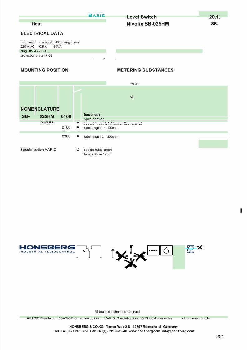
7/22/2019 General Honsberg
http://slidepdf.com/reader/full/general-honsberg 253/347
Level Switch 20.1.float Nivofix SB-025HM SB.
ELECTRICAL DATA
reed switch - wiring 0.280 change over 220 V AC 0.5 A 60VAplug DIN 43650-Aprotection class IP 65
MOUNTING POSITION METERING SUBSTANCES
water
oil
NOMENCLATUREbasic typespecificationsocket thread G1 A brass - float spansiltube length L= 100mmtube length L= 200mmtube length L= 300mmtube length L= 400mmtube length L= 500mmspecial tube lengthtemperature 120°C
All technical changes reserved
BASIC Standard BASIC Programme option VARIO Special option ⊕ PLUS Accessories not recommendable
HONSBERG & CO.KG Tenter Weg 2-8 42897 Remscheid GermanyTel. +49(0)2191 9672-0 Fax +49(0)2191 9672-40 www.honsberg.com [email protected]
025HM0100
Special option VARIO
SB-
05000400
025HM
02000300
0100
1 3 2
I
Basic
251

7/22/2019 General Honsberg
http://slidepdf.com/reader/full/general-honsberg 254/347
Level Switch 20.1.float Nivofix NR-...HK/EA NR.
GENERAL CHARACTERISTICS Male thread G2A stainless steelFlange Ø120 aluminium
TECHNICAL DATA NR-120EA1000
media temperature max. 100°C
MATERIALS
NR-050HK NR-120EAtube s.s. 1.4571 brassflange - aluminiumfloat s.s. 1.4571 s.s. 1.4571housing aluminium aluminium
HONSBERG & CO.KG Tenter Weg 2-8 42897 Remscheid GermanyTel. +49(0)2191 9672-0 Fax +49(0)2191 9672-40 www.honsberg.com [email protected]
NR-120EA0750NR-120EA1000
≥ 0.8≥ 0.8
Mechanical Level Switch for liquids in full metal design. Amagnet-equipped float triggers adjustable reed switches.
top assemblyadjustable switch value in 10mm incrementsup to 4 separate contacts
NR-050HK0500G2A NR-050HK0250
s t a i n l e s s
s t e e l
liquid densityg/cm³
≥ 0.8≥ 0.8≥ 0.8
2
NR-050HK1000NR-050HK0750
flange
a l u m i n i u m
NR-120EA...
1.31.41.61.71.01.11.3
TypeG
NR-120EA0250NR-120EA0500
750≥ 0.8 5003
750
max. number of switch contacts
(to order separately)
Lmm
NR-050HK...
15151515
≥ 0.8
4
weightkg
4
42
3
1.41000
250500
≥ 0.8
PNbar
151515
154
1000250
Basic
252

7/22/2019 General Honsberg
http://slidepdf.com/reader/full/general-honsberg 255/347
Level Switch 20.1.float Nivofix NR-...HK/EA NR.
ELECTRICAL DATA
See switch module.
MOUNTING POSITION METERING SUBSTANCES
water design stainless steel NR-050HKfor aggressive liquids
oil
NOMENCLATUREbasic typespecificationsocket thread G2A stainless steelflange Ø120 aluminiumtube length L= 250mmtube length L= 500mmtube length L= 750mmtube length L=1000mmprotection tube aluminium (flange design only)special tube length up to 2500mmcombination flange and tube stainless steel
SWITCH MODULE
Switch modules to order seperately.
reed switchwiring 0.225 n.o. or n.c.cable gland Pg13,5250 V AC , 1 A , 250 VAprotection class IP 65
180°
Pull installation rail out of the tube, The markings on the rail allowposition switch module into the a precise positioning of therail holes and connect electrical switch module.connector in switch head
All technical changes reserved
BASIC Standard BASIC Programme option VARIO Special option ⊕ PLUS Accessories not recommendable
HONSBERG & CO.KG Tenter Weg 2-8 42897 Remscheid GermanyTel. +49(0)2191 9672-0 Fax +49(0)2191 9672-40 www.honsberg.com [email protected]
The switch modules can be operated as n.o. or n.c. by aturn of 180°. Minimal distance 80mm between moduls.
0250
RSpecial optionVARIO
10000750
0250
050HK050HK
Depending on tube length up to 4 contacts per instrument, see table "technical data"
NR-
⊕ NR-000
0500
120EA
S
O
I
Basic
253

7/22/2019 General Honsberg
http://slidepdf.com/reader/full/general-honsberg 256/347
Level Transmiter 20.1.float Nivofix LC-...HM/HK LC.
GENERAL CHARACTERISTICS Male thread G1A to G2A brass/stainless steel
punctual guidance of the plastic floatsupport reliable operation evenwith contaminated liquids
LC-S45HM0250 LC-K52HK0250TECHNICAL DATA
* +1000 Ohm series resistancelength tolerance ±5mmmedia temperature max. 105°C resistance output
max. 85°C 4..20mA, 0..10V
option option option standard4..20mA , 0..10V 4..20mA , 0..10V resistor resistor locking plug plug DIN 43650-A locking plug plug DIN 43650-A
MATERIALS
LC-S4.HM LC-K52HKtube Ms58 stainless steel 1.4571float Spansil stainless steel 1.4571housing Ms58 stainless steel 1.4571 LC-S45 LC-S44 LC-K52
HONSBERG & CO.KG Tenter Weg 2-8 42897 Remscheid GermanyTel. +49(0)2191 9672-0 Fax +49(0)2191 9672-40 www.honsberg.com [email protected]
1.1LC-K52HK2000 40 ≥ 0.66 20 0 - 4741 ±144 2000 1910 1.1
0 - 3493 ±120 1500 1410LC-K52HK1500 40 ≥ 0.66 20
1.0LC-K52HK1000 40 ≥ 0.66 20 0 - 2246 ± 94 1000 910 1.1
0 - 1647 ± 83 750 690LC-K52HK0750 40 ≥ 0.66 20±280 500 510 1.0LC-K52HK0500 40 ≥ 0.66 20
LC-K52HK0250 40 ≥ 0.66 10
0.8LC-S44HM2000 20 ≥ 0.44 20 0 - 4790 ±146 2000 1930 .08
0 - 3543 ±121 1500 1430LC-S44HM1500 20 ≥ 0.44 20
0.7LC-S44HM1000 20 ≥ 0.44 20 0 - 2295 ± 95 1000 930 0.7
690LC-S45HM1000 20 ≥ 0.34 10 0 - 2055 ± 64 1000 940
500 440 0.6LC-S45HM0750 20 ≥ 0.34 10 0 - 1503 ± 52 750
20 ≥ 0.34 10 ±1860 - 4300
toleranceOhm
at max
Lmm
L1mm
0 - 1800 ±136 250 190
0 - 1500 ±1300 - 4000
reso-lution
mm
resistor Ohm *
LC-S45HM050010
Type PNbar
liguid densityg/cm³
LC-S45HM0250 20 ≥ 0.34G1 A
0.6
250 160 1.0
b r a s s
A magnet equipped float activates a reed chain inside atube which is connected to resistors comparable to apotentiometer. The gapless positioning of the sensorsprovides a continuous signal with good resolution andrepeatability.
top assemblyselectable material combinations
G1 1/2 A
s t a i n l e s s s t e e l G2 A
G weightkg
0.5
Basic
254

7/22/2019 General Honsberg
http://slidepdf.com/reader/full/general-honsberg 257/347
Level Transmiter 20.1.float Nivofix LC-...HM/HK LC.
ELECTRICAL DATA plug DIN 43650-A locking plug M12x1 - 4pole
24 V DC 50 mAresistance value see table 'technical data'potentiometer resistance 500-2000 Ω
protection class IP 65
option:
MOUNTING POSITION METERING SUBSTANCES
water design stainless steelfor aggressive liquids
oil
NOMENCLATURE For combination see table "technical data"
basic typespecificationsocket thread G1 A brass - float Spansilsocket thread G1 1/2 A brass - float Spansilsocket thread G2 A stainless steeltube length L= 250mmtube length L= 500mmtube length L= 750mmtube length L= 1000mmtube length L= 1500mmtube length L= 2000mmresistor 4..20mA output (2-wire)4..20mA output (3-wire)0..10V outputplug DIN 43650-Aconnection for locking plug M12x1 4-polespecial tube lengthtemperature 120°C
PRINCIPLE COMBINATIONS
omni-LClocal electronic unit,2xNPN and PNP switch4(0)..20mA outputgraphical LCD displaywith flashing LEDprogram ring
Flex-LCswitch- or frequency output0..10V oder 4..20mA
Switching sequence: reed 1 switches PNP, NPNreed 1+2 switchesreed 2 switchesreed 2+3 switches
All technical changes reserved
BASIC Standard BASIC Programme option VARIO Special option ⊕ PLUS Accessories not recommendable
HONSBERG & CO.KG Tenter Weg 2-8 42897 Remscheid GermanyTel. +49(0)2191 9672-0 Fax +49(0)2191 9672-40 www.honsberg.com [email protected]
brown
113
black1
0250
WS45HM
0250 BLC- S45HM
S44HMK52HK
brownlocking plug
4..20mA 2-wire+(10-30VDC) ou tput
1plug DIN 43650-A
cable
T
1
1500
Z
1000
2000
SB
V
07500500
black blue
output 0VDC
4 32 3
output
1 2+(10-30VDC)
4..20mA 3-wire
3+(10-30VDC)
Special option VARIO
W
0V
blue
24
black brown4
0..10V
reed contact
plate
resistor
float
magnet
pipe
1
2
3
+ OUTGND
1 2 3
1kOhm
+ groundC
1 4 3
1kOhm
brow n blueblack+ groundC
I
Basic
255

7/22/2019 General Honsberg
http://slidepdf.com/reader/full/general-honsberg 258/347
Level Switch 20.1.float Nivofix RW-...HK RW.HK
GENERAL CHARACTERISITICS Male thread 1/8 BSPP - 1/2 BSPT stainless steel
TECHNICAL DATARW-015HKS RW-015HKL
pressure PN 5 bar PN 6 bar media temperature max. 120°C max. 200°Cweight 110g 120 gliquid density ≥ 0.75 g/cm³ ≥ 0,70 g/cm³
MATERIALS
RW-015HKS RW-015HKLbody stainless steel 1.4301 stainless steel 1.4571float stainless steel 1.4436 stainless steel 1.4571
MOUNTING POSITION ELECTRICAL DATAreed switchwiring 0.225 n.c. or n.o. depending on installation positionplug design 250 V AC 0.5 A 50 VA
plug similar to DIN 43650-Ccontact distance 9.4mm
lead design 220 V AC 0,28 A 30 VAlead 600 mm
protection class IP 65
Installation position may influence operation!
METERING SUBSTANCES NOMENCLATUREbasic typespecification
water connection thread 1/2 BSPTsocket threadstainless steel
oil plug (only RW-015)leads
All technical changes reserved
BASIC Standard BASIC Programme option VARIO Special option ⊕ PLUS Accessories not recommendable
Mechanical Level Switch in full metal design for liquids. Amagnet-equipped float triggers a pre-fixed reed switch.
wall mountingreliablehigh temperaturegood repeatability
H
RW- 015 H015
K
K
HONSBERG & CO.KG Tenter Weg 2-8 42897 Remscheid GermanyTel. +49(0)2191 9672-0 Fax +49(0)2191 9672-40 www.honsberg.com [email protected]
SL
S
1 2 1 2
Basic
256

7/22/2019 General Honsberg
http://slidepdf.com/reader/full/general-honsberg 259/347
Level Switch 20.1.float Nivofix RWI-016PP/PV RWI.P
GENERAL CHARACTERISTICS Compression glandMale thread M16x1,5 polypropylen/PVDF
RWI-016PPTECHNICAL DATA
assembly internallyhole diameter 16.5
MATERIALS
RWI-016PP RWI-016PVbody polypropylen PVDF assembly externallyfloat polypropylen PVDF hole diameter 23seal viton viton
MOUNTING POSITION ELECTRICAL DATAreed switchwiring 0.225 n.c. or n.o. depending on installation positioncable 0.5 m250 V AC 0.5 A 50VAprotection class IP 65
Installation position may influence operation!
METERING SUBSTANCES NOMENCLATURE
basic typespecification
water compression glandpolypropylen PPPVDF
oil cablefaston clampseal silikonchange over 175 VAC 0.25 A 3VA
RWI-020HMRWI-016PPF with brass connection
version faston clamp male thrtead G3/4A
All technical changes reserved
BASIC Standard BASIC Programme option VARIO Special option ⊕ PLUS Accessories not recommendable
HONSBERG & CO.KG Tenter Weg 2-8 42897 Remscheid GermanyTel. +49(0)2191 9672-0 Fax +49(0)2191 9672-40 www.honsberg.com [email protected]
BASIC Programme option
PVDF M16x1,5 RWI-016PV
016 PP
V
polypropylen M16x1,5
RWI-
weightg
75
media temperaturemax °C
90
Type liquid densityg/cm³
75130RWI-016PP ≥ 0.6
≥ 0.75 6
PNbar
3
KF
Mechanical Level Switch in full plastic for liquids. Amagnet-equipped float triggers a pre-fixed reed switch.
assembly externally up to wall thickness of 4mmor internally up to wall thickness of 6 mmwall mountingreliablegood repeatabilty
P
M
P K
I
Basic
257

7/22/2019 General Honsberg
http://slidepdf.com/reader/full/general-honsberg 260/347
Level Switch 20.1.float Nivofix MW3/NW3-020HM/HK MW3/NW3
GENERAL CHARACTERISTICS Male thread G3/4A brass/stainless steel
TECHNICAL DATA NW3-020HM
media temperature max. 110°C
-HM20spansil
MATERIALS
MW3/NW3-020HM MW3/NW3-020HK -020HKhousing Ms58 nickel plated stainless steel 1.4305 stainlesssocket Ms58 nickel plated stainless steel 1.4571 steelwetted parts stainless steel stainless steel
1.4310 ; 1.4571 1.4310 ; 1.4571float spansil stainless steel 1.4571 optionmagnet oxyd 300 oxyd 300 ball PVDFseal NBR viton
INSTALLATION POSITION ELECTRICAL DATAMW3 NW3micro switch reed switchwiring 0.374 change over wiring 0.225 n.c. or n.o. depending
Type 250 V AC 5 A on installation positionMW3 -020HK plug DIN 43650-A 230 V AC 1 A 50 VAlliquid density protection class IP 65 plug DIN 43650-A
≥ 1g/cm³ protection class IP 65
Installation position may influence operation!
METERING SUBSTANCES NOMENCLATUREBeispielBeschreibung
water micro switchdesign stainless steel reed switchMW3/NW3-020HK socket thread G3/4A
oil for aggressive liquids brass designstainless steel designcontact for locking plug M12x1, 4-pole
VARIO float ball PVDF
All technical changes reserved
BASIC Standard BASIC Programme option VARIO Special option ⊕ PLUS Accessories not recommendable
0.35
Special option
M
weightkg
brass G 3/4 A ≥ 0.7 0.35
PNbar
Lmm
7225
K
M
HNW3-
stainless steel
020MW3-
Mechanical Level Switch for liquids with magnetictriggering of an adjustable micro switch or rees switch.
high switch capabilitywall mountingreliablegood repeatability
liquid densityg/cm³
≥ 0.9
G
G 3/4 A
H
10 76
Type
MW3 / NW3-020HMMW3 / NW3-020HK
MW3-
HONSBERG & CO.KG Tenter Weg 2-8 42897 Remscheid GermanyTel. +49(0)2191 9672-0 Fax +49(0)2191 9672-40 www.honsberg.com [email protected]
1 2 1 21 2 3 1 2 3
Basic
258

7/22/2019 General Honsberg
http://slidepdf.com/reader/full/general-honsberg 261/347
Level Switch 20.1.float Nivofix NW1-020HM/HK NW1
GENERAL CHARACTERISTICS Male thread G3/4A brass/stainless steel
TECHNICAL DATA NW1-020HM
media temperature max. 110°C
NW1-020HMMATERIALS spansil
NW1-020HM NW1-020HKhousing Ms58 stainless steel 1.4305socket Ms58 stainless steel 1.4571 NW1-020HKwetted parts stainless steel stainless steel stainless
1.4310 ; 1.4571 1.4310 ; 1.4571 steelfloat spansil stainless steel 1.4571magnet oxyd 300 oxyd 300seal NBR viton
optionINSTALLATION POSITION ball PVDF
ELECTRICAL DATAreed switchwiring 0.225 n.c. or n.o. dependingon installation position230 V AC 1 A 50 VAcable 1.5m
protection class IP 65Installation position may influence operation!
METERING SUBSTANCES NOMENCLATUREBeispielBeschreibung
water socket thread G3/4Adesign stainless steel brass designNW1-020HK stainless steel design
oil for aggressive liquids switch ATEXBASIC (product information 92.1.U1)
special cable lengthVARIO float ball PVDF
All technical changes reserved
BASIC Standard BASIC Programme option VARIO Special option ⊕ PLUS Accessories not recommendable
MK
M
HONSBERG & CO.KG Tenter Weg 2-8 42897 Remscheid GermanyTel. +49(0)2191 9672-0 Fax +49(0)2191 9672-40 www.honsberg.com [email protected]
A
0.35
Programme option
weightkg
brass G 3/4 A ≥ 0.7 0.35
PNbar
Lmm
7425
H
H
stainless steel
020MW1-
G
G 3/4 A
liquid densityg/cm³
Mechanical Level Switch for liquids with magnetictriggering of an adjustable rees switch.
high switch capabilitywall mountingreliablegood repeatability
10
Special option
80
Type
NW1-020HMNW1-020HK ≥ 0.9
1 2 1 2
I
Basic
259

7/22/2019 General Honsberg
http://slidepdf.com/reader/full/general-honsberg 262/347
Level Switch 20.1.float Nivofix CWE-025HM CWE.
GENERAL CHARACTERISTICS Male thread R1" brass
CWE-025HMTECHNICAL DATA
media temperature max. 85°C
MATERIALS
socket brass Ms58wetted parts brass Ms58float policarbonatebellow tombakcap ABSplate steel zinc coating
MOUNTING POSITION ELECTRICAL DATAmicro switch - wiring 0.391 change over 250 V AC 15(8) Acable gland M20protection class IP 65
Installation position may influence operation!
METERING SUBSTANCES NOMENCLATUREbasic typespecification
water connection thread DN25 - R1"brass designgold contacts 125 V AC / 1 A
VARIO
All technical changes reserved
BASIC Standard BASIC Programme option VARIO Special option ⊕ PLUS Accessories not recommendable
Tel. +49(0)2191 9672-0 Fax +49(0)2191 9672-40 www.honsberg.com [email protected]
Special option
HONSBERG & CO.KG Tenter Weg 2-8 42897 Remscheid Germany
M
weightkg
0.8
Lmm
232
R Type liquid densityg/cm³
PNbar
≥ 0.9 11
H M
Mechanical Level Switch for liquids. A bellow-supportedfloat triggers mechanically an adjustable micro switch.
high switch capabiitywall mountingreliablegood repeatability
H
025CWE-
CWE-025HMbrass R1"
white red blue
Basic
260

7/22/2019 General Honsberg
http://slidepdf.com/reader/full/general-honsberg 263/347
Level Switch 20.1.Float Nivofix MWI-025HM MWI.
GENERAL CHARACTERISTICS Male thread G1A brass
TECHNICAL DATA MWI-025HM
media temperature max. 180°C
MATERIALS
housing brass Ms58float stainless steel 1.4571
MOUNTING POSITION ELECTRICAL DATA2 micro switchwiring 0.392 change over 250 V AC 5 Acable gland Pg 9protection class IP 65
METERING SUBSTANCES NOMENCLATUREbasic typespecification
water socket thread G1Abrass design
oil
All technical changes reserved
BASIC Standard BASIC Programme option VARIO Special option ⊕ PLUS Accessories not recommendable
Tel. +49(0)2191 9672-0 Fax +49(0)2191 9672-40 www.honsberg.com [email protected]
liquid densityg/cm³
G 1 A
G Type
MWI-025HMbrass ≥ 0.7
H M
PNbar
hysteresismm
MWI-
20 - 3015
weightkg
1.3
HONSBERG & CO.KG Tenter Weg 2-8 42897 Remscheid Germany
MH
Mechanical Level Switch for liquids with magnetictriggering of an adjustable micro switch.
temperature 180°Chigh switch capability2 micro switch, change over wall mountingreliablegood repeatability
025
21 3 54 6
I
Basic
261
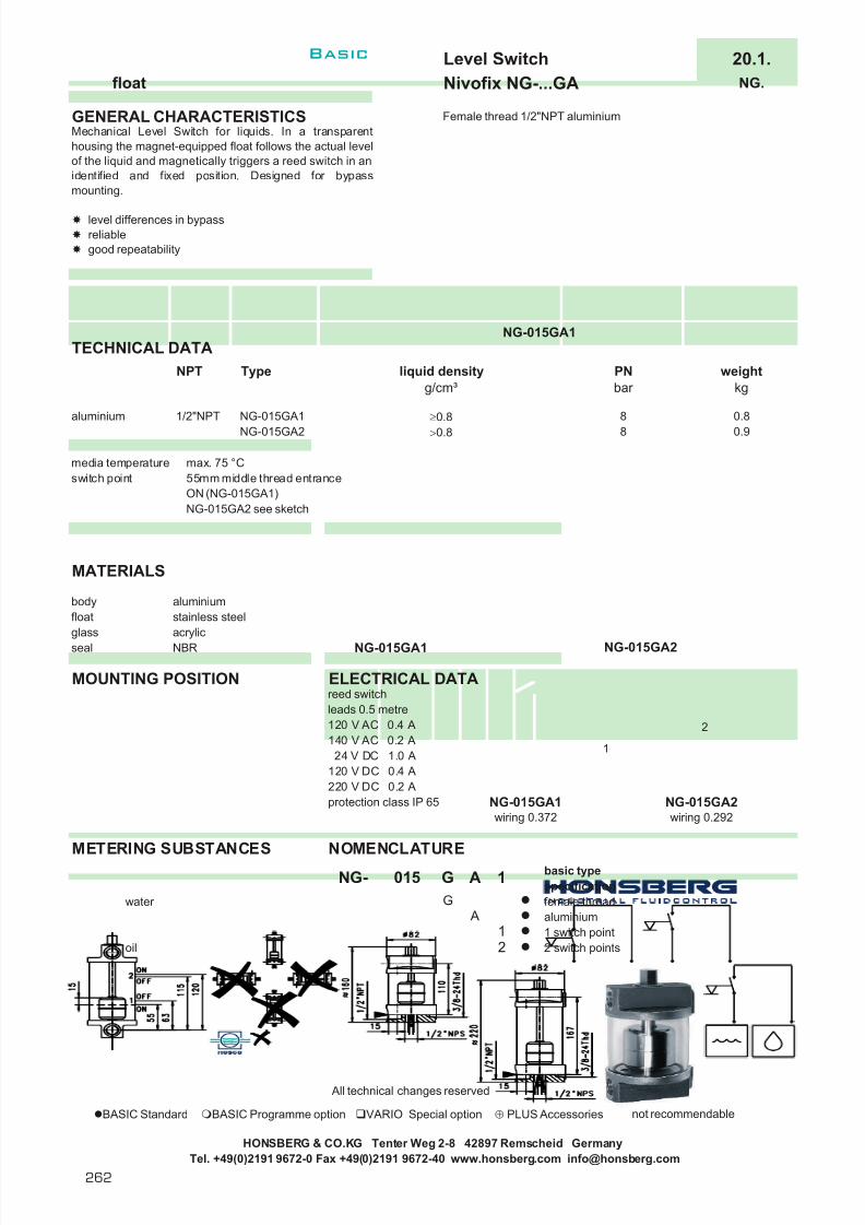
7/22/2019 General Honsberg
http://slidepdf.com/reader/full/general-honsberg 264/347
Level Switch 20.1.float Nivofix NG-...GA NG.
GENERAL CHARACTERISTICS Female thread 1/2"NPT aluminium
NG-015GA1TECHNICAL DATA
media temperature max. 75 °Cswitch point 55mm middle thread entrance
ON (NG-015GA1)NG-015GA2 see sketch
MATERIALS
body aluminiumfloat stainless steelglass acrylicseal NBR NG-015GA1
MOUNTING POSITION ELECTRICAL DATAreed switchleads 0.5 metre120 V AC 0.4 A140 V AC 0.2 A
24 V DC 1.0 A120 V DC 0.4 A220 V DC 0.2 Aprotection class IP 65 NG-015GA1 NG-015GA2
wiring 0.372 wiring 0.292
METERING SUBSTANCES NOMENCLATUREbasic typespecification
water female threadaluminium1 switch point
oil 2 switch points
All technical changes reserved
BASIC Standard BASIC Programme option VARIO Special option ⊕ PLUS Accessories not recommendable
A
Mechanical Level Switch for liquids. In a transparenthousing the magnet-equipped float follows the actual levelof the liquid and magnetically triggers a reed switch in anidentified and fixed position. Designed for bypassmounting.
level differences in bypassreliablegood repeatability
NG- 015
NG-015GA21/2"NPT
G
1
weightkg
PNbar
A
NG-015GA2
NG-015GA1 ≥ 0.8
NPT Type liquid densityg/cm³
aluminium> 0.8
2
G
1
8 0.90.88
HONSBERG & CO.KG Tenter Weg 2-8 42897 Remscheid GermanyTel. +49(0)2191 9672-0 Fax +49(0)2191 9672-40 www.honsberg.com [email protected]
1
2
Basic
262

7/22/2019 General Honsberg
http://slidepdf.com/reader/full/general-honsberg 265/347
Level Indicator 20.2.sight glass / float Nivofix NBS-010HM NBS.
GENERAL CHARACTERISTICS Male thread G3/8A brass
NBS-010HM080
TECHNICAL DATA
media temperature max. 50°C length 40-200 from length 250
weight 95g (NBS-010HM040)195g (NBS-010HM300)
vent holein the cover
MATERIALS
body brasstube natural glasssight ring PVCrod acrylicfloat spansilbuffer NBR
MOUNTING POSITION NOMENCLATUREbasic typespecificationconnection thread G3/8Asocket threadbrasslength 40 mmlength 60 mmlength 80 mmlength 100 mmlength 125 mmlength 150 mm
METERING SUBSTANCES length 200 mmlength 250 mmlength 300 mm
water length 50,70,90,175 and >300 mmconnection thread G1/2A
oil
All technical changes reserved
BASIC Standard BASIC Programme option VARIO Special option ⊕ PLUS Accessories not recommendable
100080
125150
Mechanical Level Indicator for liquids. In a sight glass afloat optically indicates the actual level.
top assemblydirect indication
040
Special option300
M
040H MNBS-010
010
VARIO
H
250
060
200
HONSBERG & CO.KG Tenter Weg 2-8 42897 Remscheid GermanyTel. +49(0)2191 9672-0 Fax +49(0)2191 9672-40 www.honsberg.com [email protected]
I
Basic
263
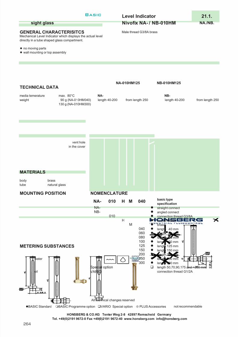
7/22/2019 General Honsberg
http://slidepdf.com/reader/full/general-honsberg 266/347
Level Indicator 21.1.sight glass Nivofix NA- / NB-010HM NA./NB.
GENERAL CHARACTERISITCS Male thread G3/8A brass
NA-010HM125 NB-010HM125TECHNICAL DATA
media temerature max. 80°C NA- NB-weight 90 g (NA-010HM040) length 40-200 from length 250 length 40-200 from length 250
130 g (NA-010HM300)
vent holein the cover
MATERIALS
body brasstube natural glass
MOUNTING POSITION NOMENCLATUREbasic typespecificationstraight connectangled connectconnection thread G3/8Asocket threadbrasslength 40 mmlength 60 mmlength 80 mmlength 100 mm
METERING SUBSTANCES length 125 mmlength 150 mmlength 200 mm
water length 250 mmlength 300 mmlength 50,70,90,175 and >300 mm
oil connection thread G1/2A
All technical changes reserved
BASIC Standard BASIC Programme option VARIO Special option ⊕ PLUS Accessories not recommendable
HONSBERG & CO.KG Tenter Weg 2-8 42897 Remscheid GermanyTel. +49(0)2191 9672-0 Fax +49(0)2191 9672-40 www.honsberg.com [email protected]
M
VARIO
H
060
125
Special option300
100
NA-
010
010NA-NB-
040H M
200250
150
040
Mechanical Level Indicator which displays the actual leveldirectly in a tube shaped glass compartment.
no moving partswall mounting or top assembly
080
Basic
264

7/22/2019 General Honsberg
http://slidepdf.com/reader/full/general-honsberg 267/347
Level Switch 22.1.infrared Nivolock NL-015HS/HK NL.
GENERAL CHARACTERISTICS Male thread 1/2" NPT steel/stainless steel
NL-015AKT05
TECHNICAL DATA
NL-015HST05NL-015HST24NL-015HSN05NL-015HSN24NL-015HKT05
NL-015HKT24NL-015HKN05NL-015HKN24
* except freezing liquids
MATERIALS
NL-015HS. NL-015HK.body steel nickel plated stainless steelglass fused glass fused glass
HONSBERG & CO.KG Tenter Weg 2-8 42897 Remscheid GermanyTel. +49(0)2191 9672-0 Fax +49(0)2191 9672-40 www.honsberg.com [email protected]
NPT weightg
5
1/2" NPT
s . s
1/2" NPT
The electro optical sensor consists of a robust metalhousing and a fused glass prism which contains aninfrared LED and a light receiver. When rising liquidimmerses the prism the light is refracted out into the liquidleaving lithe or no light to reach the receiver. Sensing thischange the receiver actuates electronic switching withinthe unit to operate an external alarmunit.
small sizesolid state integrated elctronicsno moving partssimple installation
Type
s t e e l
function
wet - signal when sensor has no contact to liquiddry - signal when sensor has contact to liquid
inputpower VDC
5
5
wet - signal when sensor
has no contact to liquiddry - signal when sensor has contact to liquid
repeataccuracy
mediatemperature
°C *
PNbar
±1mm
±1mm
±1mm
±1mm
75
75
24
524
24
24
75
75
160
160
160
160
-40 .. 100
-40 .. 100
-40 .. 100
-40 .. 100
receiver
light from LED
prism
LED
receiver
light
LED
lost inliquid
I
Basic

7/22/2019 General Honsberg
http://slidepdf.com/reader/full/general-honsberg 268/347
Level Switch 22.1.infrared Nivolock NL-015HS/HK NL.
ELECTRICAL DATA
current consumentation ca. 45 mAinput power 5 VDC or 24 VDC (optional 12 VDC)output NPN open collector
transistor output whit 10K pull up resistor
may sink 18 mA max.wires 300mmprotection class IP 64
MOUNTING POSITION METERING SUBSTANCES
design stainless steelwater for aggressive liquids
oil
NOMENCLATUREbasic typespecificationmale thread 1/2" NPTconnection thread steel nickel platedconnection thread stainless steelwet - signal when sensor has no contact to liquiddry - signal when sensor has contact to liquid
12 VDC24 VDC
All technical changes reserved
BASIC Standard BASIC Programme option VARIO Special option ⊕ PLUS Accessories not recommendable
HONSBERG & CO.KG Tenter Weg 2-8 42897 Remscheid GermanyTel. +49(0)2191 9672-0 Fax +49(0)2191 9672-40 www.honsberg.com [email protected]
015015
HKTN
T
1224
HS
NL- HS 05
functional limit- crystalline liquids- reflecting surfaces nearer than 50 mm- freezing liquids (temperature range)
black
red
0 VDC
12 VDC or 5VDC
outputw hite
load / 18mA max.
Basic
266

7/22/2019 General Honsberg
http://slidepdf.com/reader/full/general-honsberg 269/347
l Fully sealed enclosure Õ IP67
l Various electrical connectors Õ versatility
l Probe length 100 - 5000 mm Õ wide application
l contact structure alarm, Õ combination of controlsreed chain, additional in one instrumenttemperature sensor
l Float symmetry and material Õ adjustment to lowdensities
Why to use a level instrument
267
Basic

7/22/2019 General Honsberg
http://slidepdf.com/reader/full/general-honsberg 270/347
Market segments
Application
l Earth movers
l Air conditioners
l Motor technology
l Level control of water, oil and gasoline tanks in constructionmachines
l Level control of condensatel Level control of food oils
Where to use a level instrument
Honsberg & Co. KGTenter Weg 2-8 · 42897 Remscheid · GermanyP.O. Box 1103 69 · 42863 Remscheid · GermanyTel. +49(0)2191 9672-0 · Fax +49(0)2191 9672-40www.honsberg.com · [email protected]
268
Basic

7/22/2019 General Honsberg
http://slidepdf.com/reader/full/general-honsberg 271/347
Temperature
The technology A bimetal element is triggered whena pre-set temperature threshold is reached.
A diaphragm with adjustable characteristicallows adjustable temperature control.
A platinum resistance sensor[PT100/1000] produces a linear tempera-
ture-dependent signal.
Application
l Temperature monitors and transmitters are used in wide areas ofindustrial plant construction as safety components to prevent prescribed operating temperatures being undercut or exceeded oras metering devices for the continual recording of temperaturedevelopments in processes.
Advantages
l Simple yes/no monitoringl Extremely accurate temperature measurement
Concept Built-in housingConnection: Screw-in thread G1/2A to G3/4A, R1/2”PN 16 - 200Max. temperature 145 °CSignal threshold, 4[0]..20 mAAdjustable yesMaterials brass, stainless steelInstallation position anyMetering materials liquids or gases
Technical data
Contents
System description 270
Device descriptions 271
l Switchingl Metering
J
269

7/22/2019 General Honsberg
http://slidepdf.com/reader/full/general-honsberg 272/347
Honsberg & Co. KGTenter Weg 2-8 · 42897 Remscheid · GermanyP.O. Box 1103 69 · 42863 Remscheid · GermanyTel. +49(0)2191 9672-0 · Fax +49(0)2191 9672-40www.honsberg.com · [email protected]
Basic
270
System description
Device systemSturdy temperature monitors in brass or stainless steel housings areavailable for monitoring and metering temperature. Thanks to thestub-connection thread these can be installed directly in the pipeline.
BimetalA bimetal switch with a jump characteristic closes or opens when thepre-set temperature has been reached and triggers a threshold signal.
DiaphragmA temperature probe filled with an expansion fluid is used for deviceswith an infinitely variable switching point that can be selected via ascale.As temperature increases this metering material expands and acts on aspring-supported diaphragm which triggers a contact. A spring charac-
teristic is changed via the setting, thus influencing the triggering of the threshold value. Greater preliminary tension makes a greater triggeringforce necessary which in turn occurs at a higher temperature value.
Platinum resistance sensorThe temperature transmitters comprise a temperature sensorPT100/1000 resistance sensor which shows good dynamic behaviour
thanks to the small sensor diameter. The temperature-dependent change in resistance is transformed into a linear output signal4[0]..20 mA by the downstream electronics.
Function and advantages
The devices provide a wide range of problem solutions for temperaturemonitoring and metering.
The material alternatives brass or stainless steel make their use possi-ble even in aggressive mediums.
Metering materials and accuracy Both liquids and gases can be considered as metering materials. The tolerances of the monitoring devices are 5K of the final value, in thecase of the temperature transmitters 1 % of the final value.

7/22/2019 General Honsberg
http://slidepdf.com/reader/full/general-honsberg 273/347
271
m i s c e
l l a n e o u s
p a g e
a g g r e s s
i v e
g a s
/ a
i r
o i l
i n d i c a t i o n
t y p e
c o n t r o
l
n o m
i n a
l d i a m e t e r
o u t p u t s i g n a
l
o n s
i t e m e t e r i n g
m a x . p r e s s u r e
b a r
m a x . t e m p e r a t u r e
° C
w a t e r
l standard m standard option special option current data sheets can be found under www.honsberg.com
Honsberg at work
Temperature monitoring of pumps inhigh-pressure cleanersBimetal temperature switch TF1 installed in the pumphousing of high-pressure/low-pressure cleaners asoverheating protection, adjusted to 105 °C, to switchoff if this is exceeded.
TF1 male thread brass l 100 140 l l l 272male thread stainless steel l 100 140 l l l 3
TR male thread brass l 16 145 l l l 1-2 switch 273
ETS male thread stainless steel m m l m 25 80 l l l 3 274
ETSD male thread stainless steel l 25 80 l l l 3 differential 276
J
c o n t r o
l
m e a s u r e m e n t
HONSBERG & CO.KG Tenter Weg 2-8 42897 Remscheid GermanyTel. +49(0)2191 9672-0 Fax +49(0)2191 9672-40 www.honsberg.com [email protected]
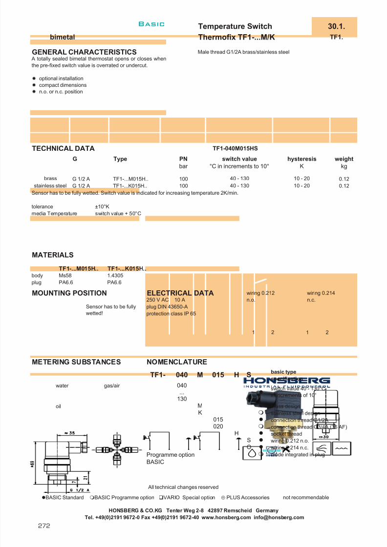
7/22/2019 General Honsberg
http://slidepdf.com/reader/full/general-honsberg 274/347
Temperature Switch 30.1.bimetal Thermofix TF1-...M/K TF1.
GENERAL CHARACTERISTICS Male thread G1/2A brass/stainless steel
TECHNICAL DATA TF1-040M015HS
Sensor has to be fully wetted. Switch value is indicated for increasing temperature 2K/min.
tolerance ±10°Kmedia Temperature switch value + 50°C
MATERIALS
TF1-...M015H.. TF1-...K015H..body Ms58 1.4305plug PA6.6 PA6.6
MOUNTING POSITION ELECTRICAL DATA wiring 0.212 wiring 0.214250 V AC 10 A n.o. n.c.plug DIN 43650-Aprotection class IP 65
METERING SUBSTANCES NOMENCLATUREbasic typespecification
water gas/air
oil brass designstainless steel designconnection thread G1/2Aconnection thread G3/4A (36 AF)socket threadwiring 0.212 n.o.wiring 0.214 n.c.diode integrated in plug
All technical changes reserved
BASIC Standard BASIC Programme option VARIO Special option ⊕ PLUS Accessories not recommendable
HONSBERG & CO.KG Tenter Weg 2-8 42897 Remscheid GermanyTel. +49(0)2191 9672-0 Fax +49(0)2191 9672-40 www.honsberg.com [email protected]
Sensor has to be fullywetted!
TF1-...M015H..
PNbar
100100
switch value°C in increments to 10°
40 - 130
G Type
brass
040
040
G 1/2 AG 1/2 A TF1-...K015H..
Programme optionBASIC
TF1-
weightkg
0.12
hysteresisK
10 - 2010 - 2040 - 130
H S015
0.12
M
switch value 40 - 130°Cin increments of 10°...
130M
SO
A totally sealed bimetal thermostat opens or closes whenthe pre-fixed switch value is overrated or undercut.
optional installationcompact dimensionsn.o. or n.c. position
015
stainless steel
K
020H
1 2 1 2
Basic
272

7/22/2019 General Honsberg
http://slidepdf.com/reader/full/general-honsberg 275/347
Temperature Switch 30.1.diaphragm Thermofix TR-015HM TR.
GENERAL CHARACTERISTICS Male thread G1/2A brass
TECHNICAL DATAadjustable range TR-015HM1 externally adjustable 50 - 130°C
TR-015HM2 externally adjustable 35 - 95°Cinternally adjustable 50 - 130°C
adjustment in 5°C incrementstolerance ±5°K TR-015HM1 TR-015HM2pressure PN 16 bar media temperature max. 145°Cambient Temperature max. 80°Chysteresis TR-015HM1 8K
TR-015HM2 5Kweight TR-015HM1 0.3kg
TR-015HM2 0.5kg
MATERIALS
body brass nickel platedimmersion sleeve brass nickel platedprobe copper nickel platedcap plastic
MOUNTING POSITION ELECTRICAL DATAmicro switchwiring 0.342 change over 250 V AC 15 A (8 A inductive)cable gland Pg13.5protection class IP 43
METERING SUBSTANCES NOMENCLATUREbasic typespecification
water gas/air connection thread R1/2"socket threadbrass design
oil 1 contact2 contactslength of pobe 200mm switch range on requestprobe stainless steel 1.4301protection class IP 54
All technical changes reserved
BASIC Standard BASIC Programme option VARIO Special option ⊕ PLUS Accessories not recommendable
015 H M
HONSBERG & CO.KG Tenter Weg 2-8 42897 Remscheid Germany
1015
TR-
The sensor probe contains a metering liquid whichexpands with increasing temperaure and by means of anflexible diaphragm triggers an adjustable micro switch.The adjustment of the micro switch is provided by anexternal adjustment dial.
externally adjustableoptional installation
H
TR-015HM1
1M
2Programme optionBASIC
Tel. +49(0)2191 9672-0 Fax +49(0)2191 9672-40 www.honsberg.com [email protected]
1 23
J
Basic
273

7/22/2019 General Honsberg
http://slidepdf.com/reader/full/general-honsberg 276/347
Temperature Transmitter 31.1.platinum resistance sensor ETS ETS.
GENERAL CHARACTERISTICS male thread G1/2A stainless steel
TECHNICAL DATArange 0..100°C with connection at locking plugs M12x1, 4poleoption temperature <0°Caccuracy 1% FSdynamics ( τ ) 5 s
operating pressure max. 25 bar operating temperature max. 80°C
(with “goose-neck” max. 250°C) with plug DIN 43650-Aoperating temperature 0..80°Cof the electronicweight 0.2kg
recessMOUNTING DIN 3852 Bl.2
“goose-neck” option for higher temperatures
MATERIALStemperature probe stainless steel 1.4571
other materials brass nickel plated, PP
HONSBERG & CO.KG Tenter Weg 2-8 42897 Remscheid GermanyTel. +49(0)2191 9672-0 Fax +49(0)2191 9672-40 www.honsberg.com [email protected]
The Temperature Transmitter consists of a PT100resistance sensor with very good dynamic behavior due tothe small diameter of the measurement probe. Thechange in resistance generated by temperature isconverted to a 4..20 mA signal proportional to temperatureby the linearised electronic. As the sensor is supplied with< 4 mA a double wire connection could be realised. At thesame time this type of sensor can be emploied as anopen circuit monitor.The temperature probe is welded to the threaded housing.Because the whole upper housing can be rotated, you canorientate your cable connection in any positionsubsequent to final assembly.
4..20 mA double wire transmitter small probe dimensionsfast respons timerotating plug connection (infinitely variable)
The sensors are installed with appropriate sealing (Teflontape or triplex etc.) in a connection piece or a T-piece of the pipe. To tighten the sensor please use only thehexagonal key provided (AF27mm). The tip of the probeshould be completely surronded by the medium when inuse. Please avoid installing in high temperature siteswhere the sensor housing is exposed to the convected
heat of the pipe. After sealing, you can turn the sensor into the correctcable input position. An over turn security limits the turnrange to nearly 360°.
Basic
274
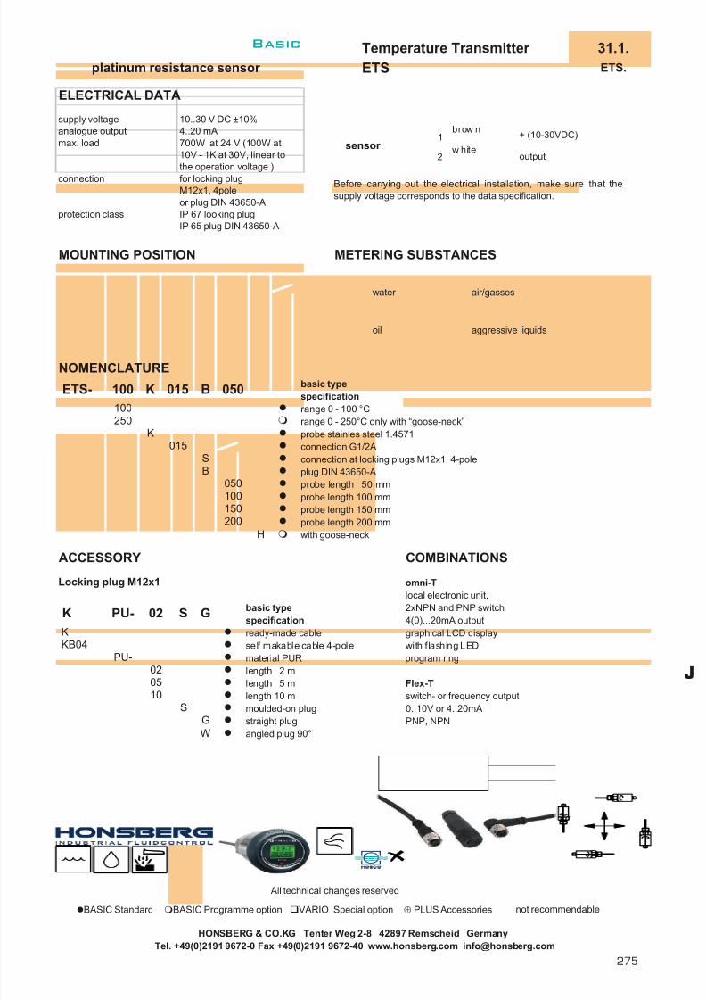
7/22/2019 General Honsberg
http://slidepdf.com/reader/full/general-honsberg 277/347
Temperature Transmitter 31.1.platinum resistance sensor ETS ETS.
ELECTRICAL DATA
10..30 V DC ±10%4..20 mA700W at 24 V (100W at10V - 1K at 30V, linear tothe operation voltage )for locking plugM12x1, 4poleor plug DIN 43650-AIP 67 looking plugIP 65 plug DIN 43650-A
MOUNTING POSITION METERING SUBSTANCES
water air/gasses
oil aggressive liquids
NOMENCLATUREbasic typespecificationrange 0 - 100 °Crange 0 - 250°C only with “goose-neck”probe stainles steel 1.4571connection G1/2Aconnection at locking plugs M12x1, 4-poleplug DIN 43650-Aprobe length 50 mmprobe length 100 mmprobe length 150 mm
probe length 200 mmwith goose-neck
ACCESSORY COMBINATIONS
Locking plug M12x1 omni-Tlocal electronic unit,
basic type 2xNPN and PNP switchspecification 4(0)...20mA outputready-made cable graphical LCD displayself makable cable 4-pole with flashing LEDmaterial PUR program ringlength 2 mlength 5 m Flex-T
length 10 m switch- or frequency outputmoulded-on plug 0..10V or 4..20mAstraight plug PNP, NPNangled plug 90°
All technical changes reserved
BASIC Standard BASIC Programme option VARIO Special option ⊕ PLUS Accessories not recommendable
HONSBERG & CO.KG Tenter Weg 2-8 42897 Remscheid GermanyTel. +49(0)2191 9672-0 Fax +49(0)2191 9672-40 www.honsberg.com [email protected]
analogue outputmax. load
connection
200 H
150100050
S
K
100
B 050
protection class
B
250
015
supply voltage
100 K 015
Before carrying out the electrical installation, make sure that thesupply voltage corresponds to the data specification.
ETS-
GK
K PU- 02 S
KB04PU-
0502
10G
S
W
+ (10-30VDC)
outputsensor
1
2
brow n
w hite
J
Basic
275

7/22/2019 General Honsberg
http://slidepdf.com/reader/full/general-honsberg 278/347
Differential Temperature Transmitter 35.1.platinum resistance sensor ETSD ETSD.
GENERAL CHARACTERISTICS Außengewinde G1/2A Edelstahl
TECHNICAL DATA
differential T1-T2: 20, 30 or 50 Kelvintemperatureaccuracy ±1 Kelvintransient time 2 minmax. pressure max. 25 bar operating temperature 0..80°Cfor electronicsmeasurement range -20..80 °CT1 optional -20..120 °C
(goose-neck)measurement range -20..120 °CT2 recessweight 0.45kg DIN 3852 Bl.2
CHARACTERISTIC CURVESExamples for measurement range20 Kelvin differential temperature
“goose-neck” option for higher temperatures
MOUNTING
MATERIALStemperature probe stainless steel 1.4571
other materials brass nickel plated, PP
HONSBERG & CO.KG Tenter Weg 2-8 42897 Remscheid GermanyTel. +49(0)2191 9672-0 Fax +49(0)2191 9672-40 www.honsberg.com [email protected]
Measurement of differential temperature between twooperating sites with lowest possible installation expenseand a 4..20 mA two wire system which is complying toindustrial standards. The sensing elements T1 and T2measure the temperature at each location by a platinumresistance sensor at the same time. T1, as well asrecording temperature, includes electronics which build upthe differential of both temperatures (T1-T2) and emitsthis via a current amplifier as a proportional 4..20 mAsignal. Two different characteristic curves are available asa standard. The electronic circuit involves a total of < 4 mA, so that a two wire system can be used.
simple recording of differential temperatureself assembly connectorslarge distance possible between twosensing elementsvariable rotating plug connectiondifferent characteristic curves possible
By means of the enclosed Sikurit seals the sensors are tightened into the Tpiece of the pipe. Please only use the hexagonal head for tightening! Takecare to locate the tip of the sensing device fully into the flow area and avoiddirect contact to pipe wall. Accordingly the upper part of the sensor with theplug connectors can be turned to any position in order to orientate proper with the cable connectors.
Typ A
0
4
20
24
-25 -20 20 25
mA
T1-T2/K
Typ B
0
4
2021
20 21.25
mA
T1-T2/K3.6 mA
Basic
276

7/22/2019 General Honsberg
http://slidepdf.com/reader/full/general-honsberg 279/347
Differential Temperature Transmitter 35.1.platinum resistance sensor ETSD ETSD.
ELECTRICAL DATA
15..30 V DC4..20 mA (2-wire)yes up to 25V (pin 1..4)up to 40V (pin 1 and 2)
yesplug DIN 43650-AIP 65
MOUNTING POSITION METERING SUBSTANCES
water air/gasses
oil aggressive liquids
NOMENCLATUREbasic typespecificationreference temperature sensor T1difference 0 K corresponds with 4mAdifference 20 K corresponds with 20mAdifference 30 K corresponds with 20mAdifference 50 K corresponds with 20mAmaterial medium contact stainless steel 1.4571sensor length 28 mmsensor length 29.6 mmsensor length 45 mmsensor length 50 mmsensor length 100 mmsensor length 150 mmsensor length 200 mmcharacteristic curve type Acharacteristic curve type Boption goose-neck
basic typespecificationreference temperature sensor T2material medium contact stainless steel 1.4571sensor length 28 mmsensor length 29.6 mmsensor length 45 mmsensor length 50 mmsensor length 100 mmsensor length 150 mmsensor length 200 mm
For a complete temperature difference test station, sensor ETSD1 and ETSD2 must be ordered !Attention! Use ETSD1 and ETSD2 with pairing serial number only.
ACCESSORIES
display connects with switch point GIA-0420VO product information 91.1.GIA.VO
All technical changes reserved
BASIC Standard BASIC Programme option VARIO Special option ⊕ PLUS Accessories not recommendable
HONSBERG & CO.KG Tenter Weg 2-8 42897 Remscheid GermanyTel. +49(0)2191 9672-0 Fax +49(0)2191 9672-40 www.honsberg.com [email protected]
other ranges on request
connectionprotection class
supply voltageanalogue outputreverse polarity proof
short circuit proof
050100
ETSD2-ETSD2-
K028
050
150
02004-
050030
150200
K
K
K 050 AETSD1-
04-ETSD1- 020
028029045
100
200
B A
H
029045
050
T2 T1
locking plugs M12x1 plug DIN 43650-A
1
2 4..20mA
+
-
1
2
4
1
2
4
3 3
J
Basic
277

7/22/2019 General Honsberg
http://slidepdf.com/reader/full/general-honsberg 280/347
Honsberg & Co. KGTenter Weg 2-8 · 42897 Remscheid · GermanyP.O. Box 1103 69 · 42863 Remscheid · GermanyTel. +49(0)2191 9672-0 · Fax +49(0)2191 9672-40www.honsberg.com · [email protected]
Why to use a temperature instrument
l Versatile sensor configurations, variety of applications
l Fixed or selectable switch point
l Rugged stainless steel enclosures
l Variety of electrical connectors
Where to use a temperature instrument
Market segments
l Pumps
l Gears
lLubrication
l Water circuits
Application
l Overheat protection in pumps
l Maximal temperature control in gears
l Continuous temperature monitoring in machine tools278
Basic
Basic

7/22/2019 General Honsberg
http://slidepdf.com/reader/full/general-honsberg 281/347
Pressure
The technology A piston moves dependent on pressureand transfers this movement to adjustablecontacts.
A diaphragm moves dependent on pressureand transfers this movement to adjustablecontacts.
A piezoresistive strain relief element produces a pressure-dependent linearoutput signal either as an open ceramicsensor or as a closed flush design.
Applicationl Pressure transmitters take over complex metering tasks in pres-
sure management and processes e.g. pressure-dependent valvecontrol.
Advantages
l Tried and tested technology in pressure monitoring and materiall Direct evaluation of contact and sensor signals
Concept built-in housingConnection screw-in thread
R1/8 to R1/4, G1/8A to G1/2APN 0.3 - 600Max. temperature 125 °CSignal threshold, 4[0]..20 mA, switchAdjustable yesMaterials brass, stainless steelInstallation position anyMetering materials liquids or gases
Technical data
Contents
System description 280
Device descriptions 281
l Switchingl Metering
279
K

7/22/2019 General Honsberg
http://slidepdf.com/reader/full/general-honsberg 282/347
Honsberg & Co. KGTenter Weg 2-8 · 42897 Remscheid · GermanyP.O. Box 1103 69 · 42863 Remscheid · GermanyTel. +49(0)2191 9672-0 · Fax +49(0)2191 9672-40www.honsberg.com · [email protected]
Basic
280
Device systemSturdy devices made of brass and stainless steel are available for moni-
toring and metering pressure and are installed directly into the pipework thanks to a stub-connection thread. Pressure is applied to a diaphragmor a piston in the case of the higher pressure ranges, which move acertain defined path against spring force. This leads to a switch being
triggered when the pre-set threshold has been reached.
Pressure transmitters work according to the tried and trusted systemof strain gauge with piezoresistive sensor structure. Integrated lineari-zed electronics produce pressure-related linear outputs of 4[0]..20 mA.
Brass and stainless steel materials allow possible applications even with
critical metering materials.
Function and advantages
The devices represent an economical possibility of monitoring andmetering pressure in a sturdy structure and with high excess pressureprotection.
Metering materials and accuracy
Both liquids and gases can be considered as metering materials.In relation to the monitoring ranges, the tolerances of the monitoringdevices are an average 0.5 bar. The metering devices work in an accu-racy range of 1 % of the final value.
System description

7/22/2019 General Honsberg
http://slidepdf.com/reader/full/general-honsberg 283/347
281
m i s c e
l l a n e o u s
p a g e
a g g r e s s
i v e
g a s
/ a
i r
o i l
i n d i c a t i o n
t y p e
c o n t r o
l
n o m
i n a
l d i a m e t e r
o u t p u t s i g n a
l
o n s
i t e m e t e r i n g
m a x . p r e s s u r e
b a r
m a x . t e m p e r a t u r e
° C
w a t e r
l standard m standard option special option current data sheets can be found under www.honsberg.com
m e a s u r e m e n t
Honsberg at work
Dosing powdered material in printing machines
PH male thread brass l 30 60 l l 3 282male thread steel l 300 60 l 3
male thread stainless steel l 300 60 l l 3 3
PM male thread brass l 30 60 l l 3 282male thread steel l 300 60 l 3
male thread stainless steel l 300 60 l l 3 3
PI male thread aluminiuml
600 60l l 3
284
VP male thread steel l 20 60 l 3 vacuum 285male thread stainless steel l 20 60 l l 3 vavuum
MD nozzle l 0,3 60 l differential 286
PS male thread stainless steel l 200 125 l l 3 287
EPS male thread stainless steel m m l m 600 80 l l 3 3 288
EPS1 male thread stainless steel m m l m 400 80 l l 3 3 290
EDP1 female thread stainless steel m m l m 400 85 l l 3 3 differential 292
In printing machines, the printed sheetsare covered with a fine layer of powder toprevent them sticking to one anotherduring stacking. The powder material issprayed by an air carrier, whereby thepressure ratios are decisive for the homo-geneity and thickness of the powder layer.In this process, Honsberg PM pressureswitches are responsible for homogenouspressure data in the 0.8 bar range and apermissible tolerance of ± 0.1 bar
K
c o n t r o
l
Powdercontainer
HONSBERG & CO.KG Tenter Weg 2-8 42897 Remscheid GermanyTel. +49(0)2191 9672-0 Fax +49(0)2191 9672-40 www.honsberg.com [email protected]

7/22/2019 General Honsberg
http://slidepdf.com/reader/full/general-honsberg 284/347
Pressure Switch 40.1.diaphragm / piston Mikropond PH / PM-...M/K/S PH./PM.
GENERAL CHARACTERISTICS Male thread R1/8" brass/stainless steel/steel
PM-002K004HS PH-002M004HS
TECHNICAL DATA
Adjustable range is indicated for increasing pressure.
media temperature max. 60°C
PM- PH-
MATERIALS
P.-002M to P.-020S to P.-...K..P.-010M P.-150S
body brass steel stainless steeldiaphragm NBR NBR NBRpiston - NBR NBRspring s.s. 1.4310 s.s. 1.4310 s.s. 1.4310cap /Typ PM NBR NBR NBRcap /Typ PH nylon nylon nylon
HONSBERG & CO.KG Tenter Weg 2-8 42897 Remscheid GermanyTel. +49(0)2191 9672-0 Fax +49(0)2191 9672-40 www.honsberg.com [email protected]
PNbar
Mechanical Pressure Switch for liquids or gaseous media. A diaphragm (low pressure) or piston (high pressure) ispre-triggered via spring with the possibilty to change thespring characteristic. During the modification a switchvalue can be selected within a certain range.
good repeatabiltyhigh pressurelow hysteresis
R1/8"
R Type adjustable rangebar (rel.)
0.15- 22 - 10
0.3
tolerance(25°C) bar
±0.2±0.3
10 - 20
piston
diaphragm
±2.00.85.5
±0.4
±5.0
±1.0
P.-010K004H.
150
0.15- 22 - 10
50 - 80150150 10
±1.0±2.0
20 - 50
50 - 150
30080P.-010M004H.80
300P.-050S004H.
P.-050K004H.
R1/8" P.-002K004H.
10 - 20
weightkg
hysteresis(25°C) bar
operationprinciple
0.15 0.08diaphragm0.2
100.08
0.30.2
piston
0.15 diaphragm
5.50.8
0.0820 - 50
±5.0
80150
±0.3
50 - 80
±0.28050 - 150
300P.-080S004H.
±0.4P.-020K004H.
P.-150S004H.
P.-080K004H.P.-150K004H.
300
b r a s
s t e e l
s t a i n l e s s s t e e l
P.-002M004H.
P.-020S004H.
R1/8"
setting sc rewprotected by cap
Basic
282

7/22/2019 General Honsberg
http://slidepdf.com/reader/full/general-honsberg 285/347
Pressure Switch 40.1.diaphragm / piston Mikropond PH / PM-...M/K/S PH./PM.
ELECTRICAL DATA wiring 0.212 wiring 0.214mechanical switch n.o. n.c.48 V AC 0.5 A (0.2A inductive)Typ PM- : plug 6.3 DIN 46224 form A
protection class IP 54Typ PH- : induction clamp
protection class IP 65 P.-...S P.-...OMOUNTING POSITION METERING SUBSTANCES
water gas/air
Attention!oil Do not use steel
body for water
NOMENCLATURE For combinations see table "technical data"
basic typespecificationpressure switch with rubber cappressure switch with plastic cap0.15 - 2 bar (rel.)
2 - 10 bar (rel.)10 - 20 bar (rel.)20 - 50 bar (rel.)50 - 80 bar (rel.)50 - 150 bar (rel.)brass design (only 2 to 10 bar)steel design (only 20 to 150 bar)stainless steel designconnection thread R1/8"socket threadwiring 0.212 n.o.wiring 0.214 n.c.mebran viton
All technical changes reserved
BASIC Standard BASIC Programme option VARIO Special option ⊕ PLUS Accessories not recommendable
HONSBERG & CO.KG Tenter Weg 2-8 42897 Remscheid GermanyTel. +49(0)2191 9672-0 Fax +49(0)2191 9672-40 www.honsberg.com [email protected]
Programme option BASIC
M
150M
004
SK
S004
H
002 H
010
a d j u s t a b l e r a n g e
080
002
050
PM-
020
OS
PM-
PH-
Basic
K
283
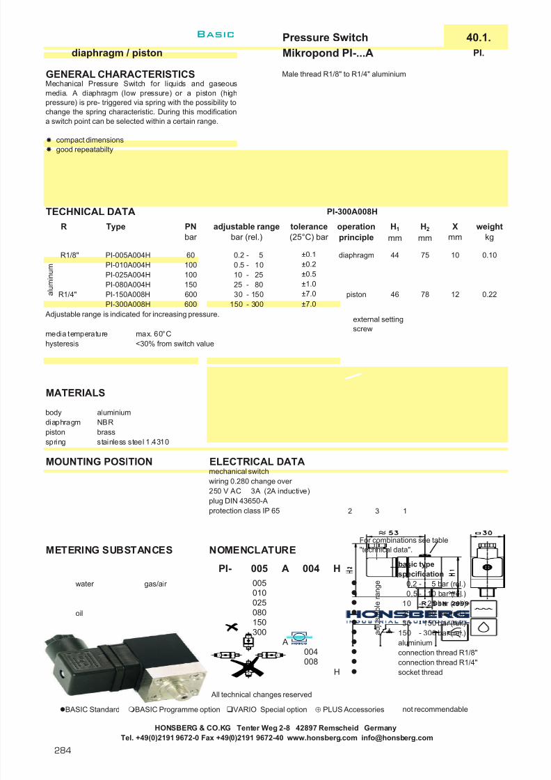
7/22/2019 General Honsberg
http://slidepdf.com/reader/full/general-honsberg 286/347
Pressure Switch 40.1.diaphragm / piston Mikropond PI-...A PI.
GENERAL CHARACTERISTICS Male thread R1/8" to R1/4" aluminium
TECHNICAL DATA PI-300A008H
Adjustable range is indicated for increasing pressure.
media temperature max. 60°Chysteresis <30% from switch value
MATERIALS
body aluminiumdiaphragm NBRpiston brassspring stainless steel 1.4310
MOUNTING POSITION ELECTRICAL DATAmechanical switchwiring 0.280 change over 250 V AC 3A (2A inductive)plug DIN 43650-Aprotection class IP 65
METERING SUBSTANCES NOMENCLATUREbasic typespecification
water gas/air 0,2 - 5 bar (rel.)0,5 - 10 bar (rel.)
10 - 25 bar (rel.)oil 25 - 80 bar (rel.)
30 - 150 bar (rel.)150 - 300 bar (rel.)aluminiumconnection thread R1/8"connection thread R1/4"socket thread
All technical changes reserved
BASIC Standard BASIC Programme option VARIO Special option ⊕ PLUS Accessories not recommendable
For combinations see table"technical data".
0.22
a d j u s t a b l e r a n g e
10
12
0.10
H008004
300
±0.2
±0.5±1.0
R Type
R1/8"
PI-025A004HPI-080A004H
PI-005A004H
weightkg
H1
mmoperationprinciple
tolerance(25°C) bar
Xmm
H2
mm
±7.0
A
010
080150
025
A
piston
diaphragm
H004005
PI- 005
78
44
46±7.0
±0.10.5 - 1010 - 2525 - 80
750.2 - 5
PI-300A008H
60
R1/4" PI-150A008H 600600
100
Mechanical Pressure Switch for liquids and gaseousmedia. A diaphragm (low pressure) or a piston (highpressure) is pre- triggered via spring with the possibility tochange the spring characteristic. During this modificationa switch point can be selected within a certain range.
compact dimensionsgood repeatabilty
100150
PNbar
adjustable rangebar (rel.)
a l u m i n u m
30 - 150150 - 300
PI-010A004H
HONSBERG & CO.KG Tenter Weg 2-8 42897 Remscheid GermanyTel. +49(0)2191 9672-0 Fax +49(0)2191 9672-40 www.honsberg.com [email protected]
2 3 1
external settingscrew
Basic
284

7/22/2019 General Honsberg
http://slidepdf.com/reader/full/general-honsberg 287/347
Pressure Switch 40.1.diaphragm Mikropond VP-900K/S VP.
GENERAL CHARACTERISTICS Male thread R1/8" stainless steel/steel
TECHNICAL DATA VP-900S004HS
media temperature max. 60°C
MATERIALS
VP-900S004H. VP-900K004H.body steel stainless steeldiaphragm NBR NBRspring s.s. 1.4310 s.s. 1.4310cap nylon nylon
MOUNTING POSITION ELECTRICAL DATA wiring 0.212 wiring 0.214mechanical switch n.o. n.c.48 V AC 0.5 A (0.2A inductive)induction clampprotection class IP 65
VP-...S VP-...O
METERING SUBSTANCES NOMENCLATUREbasic typespecification
water gas/air adjustable range 200 - 900 mbar steel design
Attention! stainless steel designoil Do not use steel connection thread R1/8"
body for water socket threadwiring 0.212 n.o.wiring 0.214 n.c.
All technical changes reserved
lBASIC Standard BASIC Programme option VARIO Special option ⊕ PLUS Accessories not recommendable
HONSBERG & CO.KG Tenter Weg 2-8 42897 Remscheid GermanyTel. +49(0)2191 9672-0 Fax +49(0)2191 9672-40 www.honsberg.com [email protected]
PNbar
A
S
H
H
OS
004
20
K
VP- 900
hysteresis(25°C)mbar
weightkg
adjustable rangembar
±50 20 0.07200 - 900
tolerance(25°C)mbar
20 200 - 900 ±50
S004900
stainless steel
Mechanical Vacuum Pressure Switch for liquids or gaseous media. A diaphragm is pre-triggered via springwith the possibility to change the spring characteristic.During this modification a switch point can be selectedwithin a certain range.
up to 0,2bar good repeatabiltycompact dimensionslow hysteresis
20 0.07
Type
VP-900S004H.VP-900K004H.
R
R1/8"R1/8"
steel
setting screwprotected by cap
Basic
K
285

7/22/2019 General Honsberg
http://slidepdf.com/reader/full/general-honsberg 288/347
(Differential) Pressure Switch 40.1.diaphragm Mikropond MD-...P006T MD.
GENERAL CHARACTERICS Nozzle Ø6,2 ABS
TECHNICAL DATA MD-006P006T
Adjustable range is indicated for increasing pressure and vertical installation.
media temperature max. 80°C MD-003P006T MD-006P006Ttolerance ±10% MD-010P006T
of selected switch value
MATERIALS
body ABSdiaphragm NBR
MOUNTING POSITION ELECTRICAL DATAmechanical switch gold contactwiring 0.280 change over 250 V AC 5(0.5)A
24 V AC 1(0.2)Acable gland Pg 9protection class IP 54
METERING SUBSTANCES NOMENCLATUREbasic typespecification
gas/air adjustable range 0.2 - 3 mbar (rel.)adjustable range 0.4 - 6 mbar (rel.)adjustable range 1.0 - 10 mbar (rel.) ABSnominal diameter DN 6nozzle
All technical changes reserved
BASIC Standard BASIC Programme option VARIO Special option ⊕ PLUS Accessories not recommendable
HONSBERG & CO.KG Tenter Weg 2-8 42897 Remscheid GermanyTel. +49(0)2191 9672-0 Fax +49(0)2191 9672-40 www.honsberg.com [email protected]
A diaphragm triggers a contact while reaching thepressure or differential pressure value selected. Theswitch point is adjusted by means of a calibrated dialwhich is arranged below the transparent cap.
optional installationgood repeatabiltylow pressure ranges
Attention! During horizontal installation theselected switch point is reduced or extendedby 0.2 mbar.
hysteresismbar
0.1 - 0.150.2 - 0.300.2 - 0.35
PNbar
0.3
adjustable rangembar (rel.)
0.4 - 6
weightkg
0.300.250.25
P
DN Type
MD-003P006T
A B S
MD-010P006T
003
6 0.15MD-006P006T
0.3
0.2 - 3
1.0 - 10
MD- 006P
006
T
010006003
T
2 3 1
Basic
286

7/22/2019 General Honsberg
http://slidepdf.com/reader/full/general-honsberg 289/347
Pressure Transmitter 41.1.thick film Mikropond PS-...K008H PS.
GENERAL CHARACTERISTICS Male thread G1/4A stainless steel
TECHNICAL DATA PS-006K008H
media temperature max. 125°Ctolerance ±0.5%hysteresis <0.2%repeatabiltiy <0.5%temperature compens. <0.02%/Kdelay <3ms
MATERIALSPlease use the six-angular area to install the sensor into the socket.
body stainless steel 1.4305 Maximum torque 100Nm
MOUNTING POSITION ELECTRICAL DATAsupply 11.5..30 V DCvoltage deviation <0.02%/Vnominal voltage 24V DC voltage peak
4..20mAmay not be surpassed
burden (U-11.5V)/0.02Aconnection plug DIN 43650-A 1(+) and 2(-)protection class IP 65
METERING SUBSTANCES NOMENCLATUREbasic typespecification
water gas/air 0 - 6 bar 0 - 10 bar 0 - 16 bar
oil 0 - 25 bar 0 - 40 bar 0 - 100 bar stainless steel 1.4305male thread G1/4Asocket threadmale thread G1/2A
All technical changes reserved
BASIC Standard BASIC Programme option VARIO Special option ⊕ PLUS Accessories not recommendable
008H
120
K
PS- 006 H006
18
G Type PNbar
PS-040K008H 1
. 4 3 0 5
G 1/4 A
PS-100K008H
PS-006K008HPS-010K008H
PS-025K008H
weightkg
0.150.15
0.150.15
016
measuring rangebar (rel.)
0 - 6
008K
0 - 25
0 - 10
200
75
30
010
0.150.15
0 - 400 - 100
r a n g e
Mechanical Pressure Switch for liquids or gasses. A thickfilm sensor provides a bridge signal which is converted byan integrated electronic into a pressure-proportional 4-20mA exit.
mechanical protection of the pressure cell
100040
PS-016K008H 48 0 - 16
Special optionVARIO
025
HONSBERG & CO.KG Tenter Weg 2-8 42897 Remscheid GermanyTel. +49(0)2191 9672-0 Fax +49(0)2191 9672-40 www.honsberg.com [email protected]
Basic
K
287

7/22/2019 General Honsberg
http://slidepdf.com/reader/full/general-honsberg 290/347
Pressure Transmitter 41.1.diaphragm EPS EPS.
GENERAL CHARACTERISTICS male thread G1/2A stainless steel
“goose-neck” option for higher temperatures
MATERIALSpressure transducer stainless steel 1.4301other materials brass nickel plated, PP, NBR
HONSBERG & CO.KG Tenter Weg 2-8 42897 Remscheid GermanyTel. +49(0)2191 9672-0 Fax +49(0)2191 9672-40 www.honsberg.com [email protected]
options
accuracyreproducibility
The pressure sensor measures pressures in liquids andgases. The strong all-metal construction enables thedevice to be universally emploied throughout industry.With flush membrane this sensor is suitable for applications with sticky fluids like glue components or other critical liquids. The pressure sensor consists of ameasurement probe (four strain gauges in thin-film polysilicon technology accommodated on a monolithic siliconsubstrate, oil filled cavity with flush diaphragm) and theevaluation electronics which converts the bridge signalinto a 4..20 mA signal proportional to the pressure. Thesensor requires less than 2 mA for a supply so that a two-wire connection can be realised. This type of connectionenables monitoring of cable defects.
4..20 mA, two-wire connectionall stainless steel diaphragmrotating plug connection (infinitely variable)
operating temp.for electronics
The sensors are screwed into a sleeve or a T-piece in thepipework using a suitable sealing material (Teflon tape,Sikurite seal, etc.). The mounting of the sensor should notcause any significant change of cross-section in the pipesystem. When tightening the sensor, be sure to only usethe proper hexagonal wrench (27mm AF). Avoid points of installation subject to high pressure shocks (see overloadlimit). After sealing the sensor can be turned into the correctposition for the cable connection. A mechanical blocklimits the total range turnable of 360°.
TECHNICAL DATAmeasurement range overload with connection at locking plugs M12x1, 4poleranges 0 - 1 4relative pressure 0 - 2,5 10overload limit 0 - 6 24(bar) 0 - 10 40
0 - 25 1000 - 60 2400 - 100 4000 - 250 6000 - 400 600additional measurement rangesabsolute pressure metering(low limit 10mbar abs.)1% / of 60°C 0,02% /°C0.5% with plug DIN 43650-A0..80°C recess
DIN 3852 Bl.2operating max. 80°C (with optiontemperature goose-neck option 125°C max.)weight 0.3kg
MOUNTING
Basic
288

7/22/2019 General Honsberg
http://slidepdf.com/reader/full/general-honsberg 291/347
Pressure Transmitter 41.1.diaphragm EPS EPS.
ELECTRICAL DATA
10..30 V DC ±10%4..20 mA700 Ω at 24 V (100 Ω at10V - 1K at 30V, linear tothe operation voltage )for locking plugM12x1, 4poleor plug DIN 43650-AIP 67 looking plug It is recommended to use shielded cable < 30 m, supply lines < 10 mIP 65 plug DIN 43650-A
MOUNTING POSITION METERING SUBSTANCES
water air/gasses
oil aggressive liquids
NOMENCLATUREbasic typespecification0 - 6 bar 0 - 25 bar 0 - 60 bar 0 - 100 bar 0 - 250 bar 0 - 400 bar relative pressureabsolute pressurematerial medium contact stainless steel 1.4301
connection G1/2Aconnection at locking plugs M12x1, 4-poleplug DIN 43650-Awith goose-neck
ACCESSORY COMBINATIONS
looking plug omni-Plocal electronic unit,
basic type 2xNPN and PNP switchspecification 4(0)...20mA outputready-made cable graphical LCD displayself makable cable 4-pole with flashing LED
material PUR program ringlength 2 mlength 5 m Flex-Plength 10 m switch- or frequency outputmoulded-on plug 0..10V or 4..20mAstraight plug PNP, NPNangled plug 90°
All technical changes reserved
BASIC Standard BASIC Programme option VARIO Special option ⊕ PLUS Accessories not recommendable
HONSBERG & CO.KG Tenter Weg 2-8 42897 Remscheid GermanyTel. +49(0)2191 9672-0 Fax +49(0)2191 9672-40 www.honsberg.com [email protected]
r a n g e
S
HB
400
K 015 SEPS-006
100
006 R
250
R
Before carrying out the electrical installation, make sure that thesupply voltage corresponds to the data specification!
025
protection class
060
A
015
K
K PU- 02 S GKKB04
PU-020510
GS
W
supply voltageanalogue outputmax. load
connection
+ (10-30VDC)
outputsensor
1
2
brow n
w hite
Basic
K
289

7/22/2019 General Honsberg
http://slidepdf.com/reader/full/general-honsberg 292/347
Pressure Transmitter 41.1.ceramics cell EPS1 EPS1.
GENERAL CHARACTERISTICS male thread G1/2A stainless steel
TECHNICAL DATAmeasurement (relative pressure, differential with connection at locking plugs M12x1, 4poleranges pressure to environment)relative pressure range burst
0 - 1 4burst pressure 0 - 2 6(bar) 0 - 5 15
0 - 10 400 - 20 600 - 50 1500 - 100 2800 - 200* 4000 - 400* 1050
* for gas applications only onrequest
1% / of 60°C 0,02% /°C with plug DIN 43650-A0.5% recess0..80°C DIN 3852 Bl.2
operating max. 80°C (with optiontemperature goose-neck option 125°C max.)weight 0.3kg
MOUNTING
“goose-neck” option for higher temperatures
MATERIALS
pressure transducer stainless steel 1.4571, Al 2O3, vitonother materials brass nickel plated, PP, NBR
HONSBERG & CO.KG Tenter Weg 2-8 42897 Remscheid GermanyTel. +49(0)2191 9672-0 Fax +49(0)2191 9672-40 www.honsberg.com [email protected]
The pressure sensor measures pressures in liquids andgases. The strong allmetal construction enables thedevice to be universally emploied throughout industry. Thepressure sensor consists of a measurement probe (four strain gauges in thickfilm technology accommodated on aceramic substrate) and the evaluation electronic whichconverts the bridge signal into a 4..20 mA signalproportional to the pressure. The sensor requires lessthan 2 mA for a supply so that a two-wire connection canbe realised. This type of connection enables line breakagemonitoring. Medium access to the diaphragm is providedby an 8mm diameter hole. The pressure cell is safelyprotected from mechanical damage by this method of construction.
4..20mA, two-wire connectionceramic measuring cell in AL 2O3
strong all-metal housingrotating plug connection (infinitely variable)
The sensors are screwed into a sleeve or a T-piece in thepipework using a suitable sealing material (Teflon tape,Sikurite seal, etc.). The mounting of the sensor should notcause any significant change of cross-section in the pipesystem. When tightening the sensor, be sure to only usethe proper hexagonal wrench (27mm AF). Avoid points of installation subject to high pressure shocks (see overloadlimit). After sealing you can turn the sensor into the correctposition for the cable connection. A mechanical blocklimits the total range turnable of 360°.
accuracyreproducebilityoperating temp.for electronics
Basic
290

7/22/2019 General Honsberg
http://slidepdf.com/reader/full/general-honsberg 293/347
Pressure Transmitter 41.1.ceramics cell EPS1 EPS1.
ELECTRICAL DATA
10..30 V DC ±10%4..20 mA700 Ω at 24 V (100 Ω at10V - 1k Ω at 30V, linear tothe operation voltage )for locking plugM12x1, 4poleor plug DIN 43650-AIP 67 looking plugIP 65 plug DIN 43650-A
MOUNTING POSITION METERING SUBSTANCES
water air/gasses
oil aggressive liquids
NOMENCLATUREbasic typespecification0 - 1 bar 0 - 2 bar 0 - 5 bar 0 - 10 bar 0 - 20 bar 0 - 50 bar 0 - 100 bar 0 - 200 bar relative pressure
material medium contact stainless steel 1.4571connection G1/2Aconnection at locking plugs M12x1, 4-poleplug DIN 43650-Awith goose-neck
ACCESSORY COMBINATIONS
looking plug omni-P1local electronic unit,
basic type 2xNPN and PNP switchspecification 4(0)...20mA outputready-made cable graphical LCD displayself makable cable 4-pole with flashing LED
material PUR program ringlength 2 mlength 5 m Flex-P1length 10 m switch- or frequency outputmoulded-on plug 0..10V or 4..20mAstraight plug PNP, NPNangled plug 90°
All technical changes reserved
BASIC Standard BASIC Programme option VARIO Special option ⊕ PLUS Accessories not recommendable
HONSBERG & CO.KG Tenter Weg 2-8 42897 Remscheid GermanyTel. +49(0)2191 9672-0 Fax +49(0)2191 9672-40 www.honsberg.com [email protected]
WG
S1005
PU-02
K
KB04K
PU- 02 S G
200
S
HB
100
supply voltage
protection class
analogue outputmax. load
connection
EPS1- S001 R K 015
020
001
r a n g e
002
010
Before carrying out the electrical installation, make sure that thesupply voltage corresponds to the data specification.
005
050
R
015K
+ (10-30VDC)
outputsensor
1
2
brow n
w hite
Basic
K
291

7/22/2019 General Honsberg
http://slidepdf.com/reader/full/general-honsberg 294/347
Differential Pressure Transmitter 45.1.Ceramics cell EDP1 EDP1.
GENERAL CHARACTERISTICS female thread G1/8 stainless steel
TECHNICAL DATA
measurement range burstranges 0 - 1 4relative pressure 0 - 2 6
0 - 5 15burst pressure 0 - 10 40(bar) 0 - 20 60
0 - 50 1500 - 100 280
differential to be specified by customer pressure range minimum: 10% of operating range
maximum: operating rangeaccuracy ±1% of full scaletemp.-coefficient <0.05% / Koperating -40..85°Ctemperatureweight 0.5 kg
MOUNTING
MATERIALS
connection stainless steel 1.4571
ceramics cell Al2O3seal Vitonother materials anodised aluminium,
stainless steel 1.4305
HONSBERG & CO.KG Tenter Weg 2-8 42897 Remscheid GermanyTel. +49(0)2191 9672-0 Fax +49(0)2191 9672-40 www.honsberg.com [email protected]
Join your pipework to P1 and P2 (see also Accessories).When sealing, ensure cleanliness during assembly
If you need to clean the pressure cells from the wettedside, you only have to undo the screws of the connector block, the electronic part is not involved. Cleaning iseffected by soft cotton buds making sure that there are noresidues left on the metering cell.
The standard version is designed
for P1>P2 (a defect does notoccur if the connections areinterchanged).
The differential pressure measurement cell is manufacturedwith two separate ceramic sensors in thick-film technology.The bridge signals are compensated for the relevant celland are converted by an integrated signal converter to a4..20 mA signal which is linear to the differential pressure.The values from the separate cells are accepted by a 14-bitconverter and microcontroller and converted into thedifference of the pressures. The microcontroller alsopermits special output signals to be emploied (pleaseinquire). Only high quality materials are exposed to theliquid. ( s.s,Viton,Al 2O3)
two-wire model for industrial applicationsideally suitable for liquid/liquid applicationscan also be used for high differential pressureshigh chemical resistance through the use of highquality materials
P1 P2
Basic
292

7/22/2019 General Honsberg
http://slidepdf.com/reader/full/general-honsberg 295/347
Differential Pressure Transmitter 45.1.Ceramics cell EDP1 EDP1.
ELECTRICAL DATA
4..20 mA (two-wire)10..30 V DCfor locking plugM12x1, 4pole Do you want to adapt a voltage input:
short-circuit proof yespolarised yesprotection class IP 67
MOUNTING POSITION METERING SUBSTANCES
water air/gasses
oil aggressive liquids
NOMENCLATUREbasic typespecification0 - 1 bar 0 - 2 bar 0 - 5 bar 0 - 10 bar 0 - 20 bar 0 - 50 bar 0 - 100 bar Relativdruck
material parts in contact with the medium stainless steel 1.4571connection G1/8connection for locking plug M12x1, 4pole
ACCESSOR Y COMBINATIONS
Locking plug M12x1 omni-DP1local electronic unit,
basic type 2xNPN and PNP switchspecification 4(0)...20mA outputready-made cable graphical LCD displayself makable cable 4-pole with flashing LEDmaterial PUR program ringlength 2 mlength 5 mlength 10 mmoulded-on plugstraight plugangled plug 90°
All technical changes reserved
BASIC Standard BASIC Programme option VARIO Special option ⊕ PLUS Accessories not recommendable
HONSBERG & CO.KG Tenter Weg 2-8 42897 Remscheid GermanyTel. +49(0)2191 9672-0 Fax +49(0)2191 9672-40 www.honsberg.com [email protected]
S
S
0001...
1000
Differential pressure range - example 0055 = 5.5 bar
(min. 10%, max. 100% of nominal pressure range)
EDP1- 0050
r a n g e o f t h e
i n d i v i d u a l c e l l .
R
020050100
005010
S004
S004
K
W
KB04K
K G
0510
G
02
PU- 02
PU-
output signalsupply voltageconnection
K
002
001001
R
+ (10..30V DC)signal output 2-10VSensor
1
w hite0 VDC
500Ohm
brow n
2
+ (10..30VDC)
signal outputSensor
1
2
brow n
w hite
Basic
K
293

7/22/2019 General Honsberg
http://slidepdf.com/reader/full/general-honsberg 296/347
294
Honsberg & Co. KGTenter Weg 2-8 · 42897 Remscheid · GermanyP.O. Box 1103 69 · 42863 Remscheid · GermanyTel. +49(0)2191 9672-0 · Fax +49(0)2191 9672-40www.honsberg.com · [email protected]
Basic
Honsberg at work
Monitoring exhaustgases in vacuum pumps
Special versions of the Honsberg pressure switches of the PM seriesare used for monitoring exhaust gases in vacuum pumps.
Pressure switch PM
The devices are calibrated to a fixed switching point of 1.5 bar abs , witha permissible tolerance of 0.22 bar and are used on the basis of thefollowing features:
l Fixed setting of the switching point including sealingl Good repeatabilityl Very low hysteresisl Protection capl Special lead and plug connection
On account of the media quality involved, the devices have Teflon dia-phragms. Contacts with gold coating are used for very small switchingcapacities. This demanding application is mastered reliably by Honsbergpressure switches.
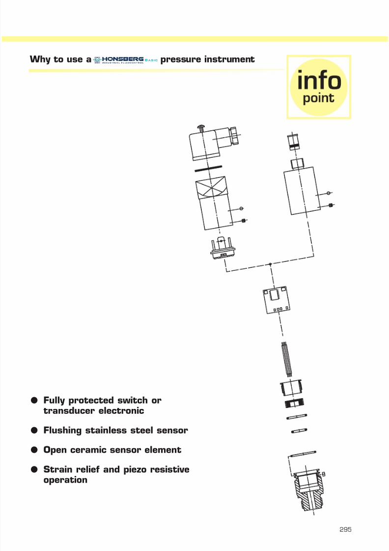
7/22/2019 General Honsberg
http://slidepdf.com/reader/full/general-honsberg 297/347
Why to use a pressure instrument
l Fully protected switch ortransducer electronic
l Flushing stainless steel sensor
l Open ceramic sensor element
l Strain relief and piezo resistive
operation
295
Basic

7/22/2019 General Honsberg
http://slidepdf.com/reader/full/general-honsberg 298/347
Honsberg & Co. KGTenter Weg 2-8 · 42897 Remscheid · GermanyP.O. Box 1103 69 · 42863 Remscheid · GermanyTel. +49(0)2191 9672-0 · Fax +49(0)2191 9672-40www.honsberg.com · [email protected]
Market segments
l Vacuum pumps
l Printing machines
l Pressure generators
l Compressors, Filters
Application
l Monitoring of exhaust gas
l Pressure monitoring in paper powder coating
l Triggering second energy supply in dual cell compressors
l Monitoring differential pressure with filters
Where to use a pressure instrument
296
Basic

7/22/2019 General Honsberg
http://slidepdf.com/reader/full/general-honsberg 299/347
Integrated Systems
flow level temperature pressure
Applicationl Universal use as threshold alarm or/and transmitter.
Advantagesl The system comprises identical components for the various
parameters in compact dimensions.
Omni
l two switching pointsl 4(0)..20mA analogue output l hysteresis selectable in magnitude and directionl graphical LCD display (increased temperature range, illumi-
nated, units in the display, incl. super-bright signalling LED)l dialogue messages in the displayl programming ring
(can be operated when wearing protective gloves)l programming protection by turning through 180° or by
removing programming ringl stainless steel housingl mineral glass (tempered, scratch and breakage proof) for
covering the displayl M12x1 connector systeml system mounting to all HONSBERG primary sensors
(rotatable)l compact dimensionsl IP 67
Flex
l 4..20 mA or 0..10 V output l switch or frequency output pnp, npnl LED switch indicator surroundl hysteresis variablel switch on delay variablel switch off delay variablel delay subsequent to supplyl high level of variation selectionl easy programming using magnet l M12x1 connector systeml identical handling of different sensorsl system mounting to all HONSBERG primary sensors
(rotatable)l stainless steel housingl compact dimensionsl IP 67
Contents
Omni
General description 298
System of instruments 299
Handling and operation 300
Technical data 300
Terminal assignment 301
Mounting 301
Device description 301
Flex
General descrition 305
System of instruments 306
Technical data 306
Terminal assignment 307
Mounting 307
Device description 307
l Switchingl Indicatingl Metering
L
297

7/22/2019 General Honsberg
http://slidepdf.com/reader/full/general-honsberg 300/347
Honsberg & Co. KGTenter Weg 2-8 · 42897 Remscheid · GermanyP.O. Box 1103 69 · 42863 Remscheid · GermanyTel. +49(0)2191 9672-0 · Fax +49(0)2191 9672-40www.honsberg.com · [email protected]
Basic
298
Omni general description
2x NPN and PNP switches:l Push pull driver offers easy set up. You set the interface as a
PNP and it is a PNP. You connect it as a NPN and it is a NPNswitch.Without any program settings !
l Independent hysteresis of switch 1 and 2.l Two point regulator possible.l Short circuit and reverse power protected.
4(0)...20mA output:l The 3 wire design offers a 0..10V output, too.l Programmable span for best fit to the application.l Select 4 or 0...20mA with the parameter setting at the sensor
(program ring).
flashing LED:l Additional bright indicator, to read messages on the display.
graphic LCD display:l Guarantee of best human interface and flexibility.l Illuminated transparent-reflex design.
Even good contrast in bright sun or in darkness.l Best temperature range (-20...+70°C).l
Select units for US or European market.
Stainless steel housing with toughened glass front:l Small (diameter 35mm) and rugged design, even for outdoor
applications.l IP 67l Easy to keep the instrument clean (flush front)!l Head can be turned for alignment after installation.
A mechanical block limits the total range turnable of 360°.
program ring:l No weak parts (as touch panels, potentiometers ...)
to enter parametersl Manual lock by turning the ring (easy!)
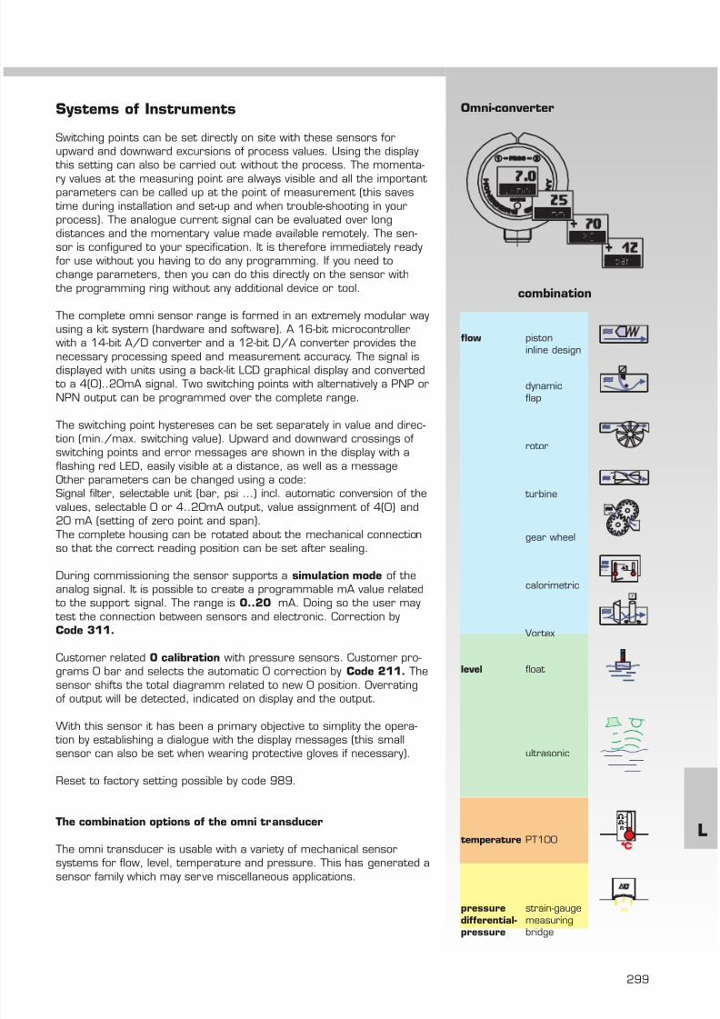
7/22/2019 General Honsberg
http://slidepdf.com/reader/full/general-honsberg 301/347
299
Systems of Instruments
Switching points can be set directly on site with these sensors forupward and downward excursions of process values. Using the display
this setting can also be carried out without the process. The momenta-
ry values at the measuring point are always visible and all the important parameters can be called up at the point of measurement (this saves
time during installation and set-up and when trouble-shooting in yourprocess). The analogue current signal can be evaluated over longdistances and the momentary value made available remotely. The sen-sor is configured to your specification. It is therefore immediately readyfor use without you having to do any programming. If you need tochange parameters, then you can do this directly on the sensor with
the programming ring without any additional device or tool.
The complete omni sensor range is formed in an extremely modular wayusing a kit system (hardware and software). A 16-bit microcontrollerwith a 14-bit A/D converter and a 12-bit D/A converter provides the
necessary processing speed and measurement accuracy. The signal isdisplayed with units using a back-lit LCD graphical display and converted
to a 4(0)..20mA signal. Two switching points with alternatively a PNP orNPN output can be programmed over the complete range.
The switching point hystereses can be set separately in value and direc- tion (min./max. switching value). Upward and downward crossings ofswitching points and error messages are shown in the display with aflashing red LED, easily visible at a distance, as well as a messageOther parameters can be changed using a code:Signal filter, selectable unit (bar, psi ...) incl. automatic conversion of the
values, selectable 0 or 4..20mA output, value assignment of 4(0) and20 mA (setting of zero point and span).
The complete housing can be rotated about the mechanical connectionso that the correct reading position can be set after sealing.
During commissioning the sensor supports a simulation mode of theanalog signal. It is possible to create a programmable mA value related
to the support signal. The range is 0..20 mA. Doing so the user may test the connection between sensors and electronic. Correction byCode 311.
Customer related 0 calibration with pressure sensors. Customer pro-grams 0 bar and selects the automatic 0 correction by Code 211. Thesensor shifts the total diagramm related to new 0 position. Overratingof output will be detected, indicated on display and the output.
With this sensor it has been a primary objective to simplity the opera- tion by establishing a dialogue with the display messages (this smallsensor can also be set when wearing protective gloves if necessary).
Reset to factory setting possible by code 989.
The combination options of the omni transducer
The omni transducer is usable with a variety of mechanical sensorsystems for flow, level, temperature and pressure. This has generated asensor family which may serve miscellaneous applications.
L
Omni-converter
flow pistoninline design
dynamicflap
rotor
turbine
gear wheel
calorimetric
Vortex
level float
ultrasonic
temperature PT100
pressure strain-gaugedifferential- measuringpressure bridge
combination

7/22/2019 General Honsberg
http://slidepdf.com/reader/full/general-honsberg 302/347
Honsberg & Co. KGTenter Weg 2-8 · 42897 Remscheid · GermanyP.O. Box 1103 69 · 42863 Remscheid · GermanyTel. +49(0)2191 9672-0 · Fax +49(0)2191 9672-40www.honsberg.com · [email protected]
Basic
300
Handling and Operation
The program ring can be geared into pos.1 or pos 2 the following per-formances can be selected:
Display of parameters with Pos. 1l Switching points S 1 and S 2: Switching points in the selected
unit.l Hysteresis direction of S1 and S2:
Max = Hysteresis under S1 or S2Min = Hysteresis above S1 or S2
l Hysteresis Hyst 1 and Hyst 2:Hysteresis values of the switching points in the selected unit.
l Code:After entering the code 111 other parameters can be set (shouldonly occur if necessary):
l Filter: Selectable filter constant in s (affects display and output).l Units: e.g. bar or psi …l Output: 0..20mA or 4..20mAl 4 (0) mA: Value specification for 4 (0) mAl 20mA: Value specification for 20mA
Editing with Pos. 2l Turn the ring gap to Pos. 2 and a flashing “cursor” appears sho-
wing the position to be changed. By repeated turning to Pos. 2 the values are increased and by turning to Pos. 1 you obtain thenext position. Each position can be edited in this way. If no actionis made within 5 s, the device returns to the normal display sec-
tion without the change being accepted.
Saving the change with Pos. 1l Turning 1x to Pos. 1 after quitting the last value signifies accep-
tance of the change.
The programming ring can be pulled off, turned through 180° andreplaced. Then programming is no longer possible on turning the ringfurther.
Technical Data
supply voltage typically 18…30V (see separate data sheets)power consumption typically <1W (see separate data sheets)measurement ranges see separate data sheetsaccuracy typically 1% FS (see separate data sheets)
reproducibility typically 0,1% FS (see separate data sheets)operating temperature -20..70 °Cstorage temperature -20..80 °Csignal output 4(0) -20mA, 2(0) -10V through
500 Ohm termination resistanceswitching points PNP or NPN selectable, 300mA loadS1 and S2 in sum max., programmable as min.
or max. value, short-circuit proof,reverse-polarity proof
hysteresis adjustable, position of hysteresisdepends on min or max.
display graphical LCD display extended temperature range -20 ... 70°C,32x16 pixels, back-lit, shows valueand units, LED signalling lamp withsimultaneous message in display.
connection at locking plug M 12x1,5 poleprotection IP 67material see separate data sheets
The programming ring can beswivelled to Pos. À and Pos. Á .The following are actions possible:
Example of hysteresis setting:S1 as max. switching point and asmin. switching point:
The omni calibration ring with inte-grated magnet is responsible for
the functional detection of theinstrument.
By position the central partition of the ring to pos.1 or 2 a test signal
is activated. The neutral position is the centre between pos. 1 + 2
principle :Pos. 1 = look or next stepPos. 2 = modification

7/22/2019 General Honsberg
http://slidepdf.com/reader/full/general-honsberg 303/347
Terminal assignment
The switchpoints are changing to PNP or NPN depending to your inter-face automaticly. Please you use shielded cable, signal lines < 30m andpower supply lines < 10m.
MountingPlease refer to the separate sensor description
Device descriptionPlease send for our Omni cataloque for detailed device description
omni MR1K/HD1K/HD1KV/HR1M
A mechanical spring-supported pistonis deflected by the flow. The flow-proportional position of the piston is
transmitted to an analogue hall sensor via a magnet.
l Pistonl Female thread DN 8-50l Hall-Sensorl Ranges from
0.4-150 l/minl Pressure stage PN 200l Max. temperature 150 °Cl Brass material
l Dynamic flapl DN 8-20 internal threadl Range: 1 - 80 l/minl Max. temperature: 60 °Cl Material: brass/copper
Dimension
primary-sensor omni-electronic
L
301
omni-XF
The flowing liquids move a thin springyflap that covers the entire flow area. Amagnet on the flap creates a changingmagnetic field, which is detected by aHall sensor, when the flap is moved.Due to the spring-like quality of the flap
and the molded stop, even strongimpacts caused by the water areabsorbed well.
Flow meters
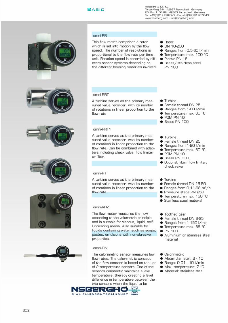
7/22/2019 General Honsberg
http://slidepdf.com/reader/full/general-honsberg 304/347
Honsberg & Co. KGTenter Weg 2-8 · 42897 Remscheid · GermanyP.O. Box 1103 69 · 42863 Remscheid · GermanyTel. +49(0)2191 9672-0 · Fax +49(0)2191 9672-40www.honsberg.com · [email protected]
Basic
302
l Turbinel Female thread DN 25l Ranges from 1-80 l/minl Temperature max. 60 °Cl POM PN 10l Brass PN 10Ol Optional: filter, flow limiter,
check valve
l Toothed gearl Female thread DN 8-25l Ranges from 1-150 l/minl Temperature max. 85 °Cl PN 100l Aluminium or stainless steel
material
l Turbinel Female thread DN 15-50l Ranges from 0.11-68 m 3 /hl Pressure stage PN 250l Temperature max. 150 °Cl Stainless steel material
omni-RR
This flow meter comprises a rotorwhich is set into motion by the flowspeed. The number of resolutions isproportional to the flow rate per timeunit. Rotation speed is recorded by diff-erent sensor systems depending on
the different housing materials involved.
l Rotorl DN 10-200l Ranges from 0.5-60 l/minl
Temperature max. 100 °Cl Plastic PN 16l Brass/ stainless steel
PN 100
omni-RRT
A turbine serves as the primary mea-sured value recorder, with its numberof rotations in linear proportion to theflow rate
l Turbinel Female thread DN 25l Ranges from 1-80 l/minl Temperature max. 60 °Cl POM PN 10l Brass PN 10O
omni-RRT1
A turbine serves as the primary mea-sured value recorder, with its numberof rotations in linear proportion to theflow rate. Can be combined with adap-
ters including check valve, flow limiteror filter.
omni-RT
A turbine serves as the primary mea-sured value recorder, with its numberof rotations in linear proportion to theflow rate
omni-VHZ
The flow meter measures the flowaccording to the volumetric principleand is suitable for viscous, liquid, self-
lubricating media. Also suitable forliquids containing water such as soaps,pastes, emulsions with non-abrasiveproperties.
omni-FIN
The calorimetric sensor measures lowflow rates. The calorimetric concept of the flow sensors is based on the useof 2 temperature sensors. One of thesensors constantly maintains a level
temperature, thereby creating a leveldifference in temperature between the
two sensors when the liquid to bemeasured stands still.
l Calorimetricl Meter diameter: 6 - 10l Range: 0.01 - 10 l/minl Max. temperature: 7 °Cl Material: stainless steel

7/22/2019 General Honsberg
http://slidepdf.com/reader/full/general-honsberg 305/347
303
l Vortexl DN 8-25 internal threadl Range: 0.6 - 240 l/minl
Max. temperature: 80 °Cl Material: brass
Level meters
l Reed switch chainl Length from 250-2000 mml Temperature max. 105 °Cl Brass/stainless steel
material
l Ultrasonicl Range from 100-2500 mml Temperature max. 70°Cl Material PET / POM
L
omni-CF
A small triangular piece that covers theentire cross-section of the flowmetercreates a vortex in the flow (Karmann
vortex, vortex effect). The vortexfrequency is proportional to the flowrate and is detected by a Piezo sensor
that is located behind the triangularpiece. The entire unit, vortex piece andsensor, is designed as module and isinserted into the pipe. Thus, the flow-meter and the entire measuring unit can be separated quickly.
l Calorimetricl Nominal diameter
from DN 10l Ranges 1-150 cm/sl Pressure range PN 200l Temperature max. 70 °Cl Stainless steel material
omni-F
The calorimetric principle of flow moni- toring is based on two temperaturesensors. One of these sensors is hea-
ted constantly so that there is a con-stant difference in temperature bet-ween the two temperature sensorswhen the metering material is at astandstill.
omni-LC
A float fitted with a magnet switches areed chain within the slide pipe whichis equipped with resistors like a poten-
tiometer. Safe level detection is achie- ved thanks to the switching statesoverlapping. The resolution is up to
10-20 mm and has good repeatabilityqualities.
omni-L
The sensor consists of the primarysensor, an ultrasonic sensor, whichdetermines in a non-contact mannerdistances to materials of various types(liquids, bulk goods, solids) and the eva-luation electronics. The ultrasonic sen-
sor operates according to the principleof the measurement of propagation time. Transmitted ultrasonic pulses arereflected at the surface and arriveback at the converter after an echoperiod

7/22/2019 General Honsberg
http://slidepdf.com/reader/full/general-honsberg 306/347
304
Honsberg & Co. KGTenter Weg 2-8 · 42897 Remscheid · GermanyP.O. Box 1103 69 · 42863 Remscheid · GermanyTel. +49(0)2191 9672-0 · Fax +49(0)2191 9672-40www.honsberg.com · [email protected]
Basic
Temperature meters
l PT100l Ranges from 0-100 °Cl Temperature max. 100 °Cl Stainless steel material
Pressure meters
l Front-flush diaphragm/ceramic cell
l Range up to 400 barl Temperature max. 120 °Cl Stainless steel material
l Ceramic Celll Range from 20O barl Temperature max. 70 °Cl Stainless steel material
omni-P/P1
The pressure meters comprise aprimary sensor and the integratedevaluation electronics.The primary sensor is available in twodifferent technologies.
omni-DP1
The differential pressure measurement cell is manufactured with two separateceramic sensors in thick-film technolo-gy. The bridge signals are temperaturecompensated on the relevant cell.The medium is exposed to high qualitymaterials only such as Al 2 O3 ceramic,stainless steel and Viton 0-rings and is
therefore ideally suitable forliquid/liquid applications.
omni-T
The primary sensor is a PT100 resi-stance sensor in thin-film technologywhich offers a very good response time
thanks to the 4 mm lance thickness.

7/22/2019 General Honsberg
http://slidepdf.com/reader/full/general-honsberg 307/347
305
Flex general description
analogue output:l 4..20 mA or 0..10 V
switch:l PNP, NPN or NPN oc (open collector) switchl min-, max-switch or frequency-output
flashing LED:l yellow LED for switching output
(ON = OK /OFF = alarm)
Programming
A calibration magnet pinched to the instrument may be used to select the switch point or full scale of the analogue output. The calibrationspot is clearly identified on the label.
flow
temperature
pressure
level
Hold magnet
Hold magnet to the point and theactual value will be the switch point.
L

7/22/2019 General Honsberg
http://slidepdf.com/reader/full/general-honsberg 308/347
306
Honsberg & Co. KGTenter Weg 2-8 · 42897 Remscheid · GermanyP.O. Box 1103 69 · 42863 Remscheid · GermanyTel. +49(0)2191 9672-0 · Fax +49(0)2191 9672-40www.honsberg.com · [email protected]
Basic
System of Instuments
The Flex-electronic linearised and conditions the primary signal to a stan-dard 4..20 mA or 0..10 V output and offers a flexible switch alarm.
The sensor operate by a 16-bit processor, a 12-bid a/d and 12-bid d/aconverter. Linearization and calibration is provided automatically. A flashmemory guarantees interchange ability of all program parameters.
The signal options are pnp/npn transistor output or a frequency signal.The analogue output 4..20 mA or 0..10 V are available.
All signal configurations are subjected to highly modular selection sche-ma by magnetic calibration.
Options available:l variable span of analogue outputsl variable hysteresisl min or max switchl inversion of output signall window functionl delay subsequent to voltage input l switch delay (on/off)
The combination options of the Flex transducer
The Flex transducer is usable with a variety of mechanical sensorsystems for flow, level, temperature and pressure. This has generated asensor family which may serve miscellaneous applications.
Technical Data
supply voltage typically 18..30V (see separate data sheets)power consumption typically <100mA
(see separate data sheets)measurement ranges see separate data sheetsaccuracy typically 1% FS (see separate data sheets)reproducibility typically 0,1% FS (see separate data sheets)operating temperature -20..70 °Cstorage temperature -20..80 °Csignal output 4..20 mA or 0..10 V DCswitching output transistor output PNP or NPN
(short circuit proof/reverse polarityprotected) I out = 100mA max.
hysteresis see separate data sheets
display yellow LED for switching output (ON = OK /OFF = alarm)
connection for locking plug M 12 x 1, 4-polprotection class IP 67material see separate data sheets
Dimension
Flex-converter
combination
flow pistoninline design
dynamicflap
rotor
turbine
gear wheel
calorimetric
Vortex
level float
temperature PT100
pressure strain-gautemeasuringbridge

7/22/2019 General Honsberg
http://slidepdf.com/reader/full/general-honsberg 309/347
307
L
Pin configuration
Please use shielded cables, less than 30 m in length and supplylines < 10 m.
InstallationPlease see the individual sensor descriptions.
Device descriptionPlease send for our Flex catalogue for detailed device descriptions.
Flex-MR1K/HD1K/HD2K/HR1M
A mechanical spring-supported pistonis deflected by the flow. The flow-proportional position of the piston is
transmitted to an analogue Hall sensor via a magnet.
Flex-XF
The flowing liquids move a thin springyflap that covers the entire flow area. Amagnet on the flap creates a changingmagnetic field, which is detected by aHall sensor, when the flap is moved.Due to the spring-like quality of the flapand the molded stop, even strongimpacts caused by the water areabsorbed well.
Flow meters
l Pistonl Female thread DN 8-50l Hall-Sensorl Ranges from
0.4 - 150 l/minl Pressure stage PN 200l Max. temperature 150 °Cl Brass material
l Dynamic flapl DN 8-20 internal threadl Range: 1 - 80 l/min.l Max. temperature: 60 °Cl Material: brass/plastic

7/22/2019 General Honsberg
http://slidepdf.com/reader/full/general-honsberg 310/347
308
Honsberg & Co. KGTenter Weg 2-8 · 42897 Remscheid · GermanyP.O. Box 1103 69 · 42863 Remscheid · GermanyTel. +49(0)2191 9672-0 · Fax +49(0)2191 9672-40www.honsberg.com · [email protected]
Basic
l Turbinel Female thread DN 25l Ranges from 1-80 l/minl Temperature max. 60 °Cl POM PN 10l Brass PN 100
l Turbinel Female thread DN 25l Ranges from 1-80 l/minl Temperature max. 60 °Cl POM PN 10l Brass PN 100l Optional: filter, flow limiter,
check valve
l Turbinel Female thread DN 15-50l Ranges from 0.11-68 m³/hl Pressure stage PN 250l Temperature max. 150 °Cl Stainless steel material
Flex-RRT
A turbine serves as the primary mea-sured value recorder, with its numberof rotations in linear proportion to theflow rate.
Flex-RRT1
A turbine serves as the primary mea-sured value recorder, with its numberof rotations in linear proportion to theflow rate. Can be combined with adap-
ters including check valve, flow limiter
Flex-RT
A turbine serves as the primary mea-sured value recorder, with its numberof rotations in linear proportion to theflow rate.
Flex-RR
This flow meter comprises a rotorwhich is set into motion by the flowspeed. The number of resolutions isproportional to the flow rate per timeunit. Rotation speed is recorded by diff-erent sensor systems depending on
the different housing materials involved.
l Rotorl DN 10-200l Ranges from 0.5-60 l/minl Temperature max. 100 °Cl Plastic PN 16l Brass/stainless steel
PN 100

7/22/2019 General Honsberg
http://slidepdf.com/reader/full/general-honsberg 311/347
309
L
l Toothed gearl Female thread DN 8-25l Ranges from 1-150 l/minl Temperature max. 85 °Cl PN 100l Aluminium or stainless steel
material
Flex-VHZ
The flow meter measures the flowaccording to the volumetric principleand is suitable for viscous, liquid, self-
lubricating media. Also suitable forliquids containing water such as soaps,pastes, emulsions with non-abrasiveproperties.
l Calorimetricl Nominal diameter
from DN 10l
Ranges 1-150 cm/sl Pressure range PN 200l Temperature max. 70 °Cl Stainless steel material
Flex-F
The calorimetric principle of flow moni- toring is based on two temperaturesensors. One of these sensors is hea-
ted constantly so that there is a con-stant difference in temperature bet-ween the two temperature sensorswhen the metering material is at astandstill.
l Calorimetricl Pipe diameter: 6 - 10l Range: 0.01 - 10 l/minl PN 200 pressure levell Max. temperature: 70 °Cl Material: stainless steel
Flex-FIN
The calorimetric sensor measures lowflow rates. The calorimetric concept of the flow sensors is based on the useof 2 temperature sensors. One of thesensors constantly maintains a level
temperature, thereby creating a leveldifference in temperature between
the two sensors when the liquid to bemeasured stands still.
l Vortexl DN 8-25 internal threadl Range: 0.6 - 240 l/minl Max. temperature: 80 °Cl Material: brass
Flex-CF
A small triangular piece that covers theentire cross-section of the flowmetercreates a vortex in the flow (Karmann
vortex, vortex effect). The vortexfrequency is proportional to the flowrate and is detected by a Piezo sensor
that is located behind the triangularpiece. The entire unit, vortex piece andsensor, is designed as module and isinserted into the pipe. Thus, the flow-meter and the entire measuring unit can be separated quickly.
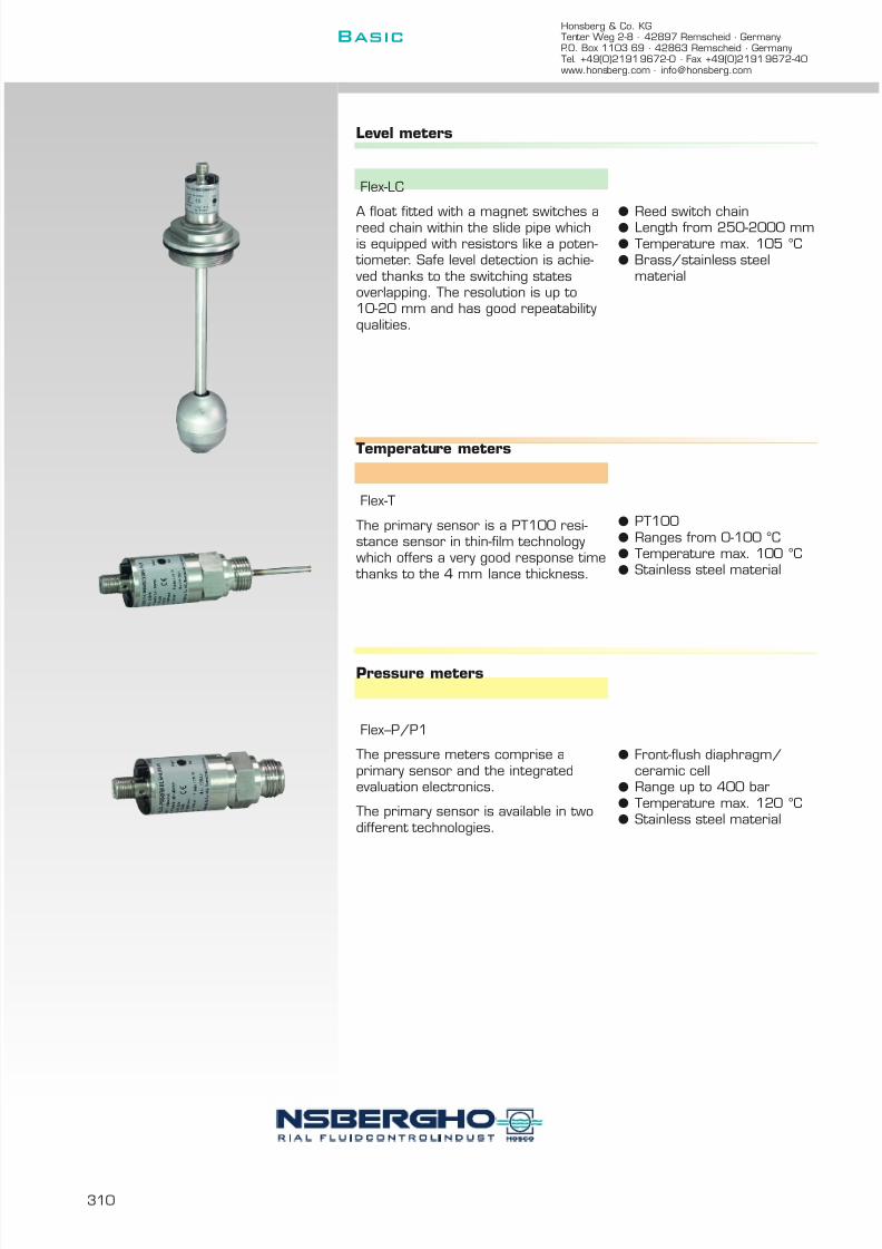
7/22/2019 General Honsberg
http://slidepdf.com/reader/full/general-honsberg 312/347
310
Honsberg & Co. KGTenter Weg 2-8 · 42897 Remscheid · GermanyP.O. Box 1103 69 · 42863 Remscheid · GermanyTel. +49(0)2191 9672-0 · Fax +49(0)2191 9672-40www.honsberg.com · [email protected]
Basic
Flex-LC
A float fitted with a magnet switches areed chain within the slide pipe whichis equipped with resistors like a poten-
tiometer. Safe level detection is achie- ved thanks to the switching statesoverlapping. The resolution is up to10-20 mm and has good repeatabilityqualities.
Flex-T
The primary sensor is a PT100 resi-stance sensor in thin-film technologywhich offers a very good response time
thanks to the 4 mm lance thickness.
Flex--P/P1
The pressure meters comprise aprimary sensor and the integratedevaluation electronics.
The primary sensor is available in twodifferent technologies.
lReed switch chainl Length from 250-2000 mm
l Temperature max. 105 °Cl Brass/stainless steel
material
l PT100l Ranges from 0-100 °Cl Temperature max. 100 °Cl Stainless steel material
l Front-flush diaphragm/ceramic cell
l Range up to 400 barl Temperature max. 120 °Cl Stainless steel material
Level meters
Temperature meters
Pressure meters

7/22/2019 General Honsberg
http://slidepdf.com/reader/full/general-honsberg 313/347
311
Transducers
The technology Honsberg supplies a range of signal
transducers which can be used in com-bination with Honsberg devices or evenas stand-alone units within the context of the metering task set.
Application
Evaluation or conversion of sensor signals
l Signal transducersl Amplifiersl EX-amplifiersl Relaysl Countersl Display units
Advantages
l These components have been designed to match Honsbergdevices, and support operation and safety.
Input Þ Input
Frequency Þ Ex-separation[switch, threshold]4[0]..20 mA, 0..10 V display, trend,frequency minimisinglinearizing
Analogue Þ Frequencyswitch, thresholdnormalisation, linearizingdisplay, trend4[0]..20 mA, 0..10 V
Contents
Summary 312
Device descriptions 313
l Signal processing
M

7/22/2019 General Honsberg
http://slidepdf.com/reader/full/general-honsberg 314/347
Honsberg & Co. KGTenter Weg 2-8 · 42897 Remscheid · GermanyP.O. Box 1103 69 · 42863 Remscheid · GermanyTel. +49(0)2191 9672-0 · Fax +49(0)2191 9672-40www.honsberg.com · [email protected]
Basic
312
The combination

7/22/2019 General Honsberg
http://slidepdf.com/reader/full/general-honsberg 315/347
313
p a g e
t y p e
d e s c r
i p t i o n
l standard m standard option special option all data sheets available under www.honsberg.comM
EFFS frequency switch 314EFFI frequency sensor with current output 315EFFF frequency/frequency converter 316EFFU frequency sensor with voltage output 317
EEV1 Ex-amplifier 2-wire-sensors (I > Namur) 318EEV2 Ex-amplifier Namur 318
WE Isolating switching amplifier with relay output 319
MSR010 Multifunction relay 319
EEZ-904 Counter 319
ESA1 Local electronic unit for frequency generating sensors 319
ESK2 Local electronic unit for frequency generating sensors 320
ESK3 Local electronic unit for frequency generating sensors 320
GIA Display with switching point 320
ELC Display for level meter LC 320
HONSBERG & CO.KG Tenter Weg 2-8 42897 Remscheid GermanyTel. +49(0)2191 9672-0 Fax +49(0)2191 9672-40 www.honsberg.com [email protected]

7/22/2019 General Honsberg
http://slidepdf.com/reader/full/general-honsberg 316/347
Frequency Switch 85.1.converter EFFS EFFS.
TERMINAL ASSIGNMENT
Sensor with adjustable frequency limitCan be configured by user via pluggable pin (Teach-In)LED indication of switch statusM12x1 industry locking plug system
ADVANTAGE
DIMENSIONS
PROGRAMMING
Adjust set frequency (= set flow) in the system.
NOMENCLATURE
basic typespecification
TECHNICAL DATA Hallbiased Hall
10..30 V DC inductive< 20 mA (without load) NPNNPN or PNP PNPmax. 200 mA NPN open collector 4..10000 Hz min. switchfor locking plug M12x1, 4-pole max. switchReservation according to DESINA locking plug M12x1, 4pole
materials housing nickel plated brass, PA66IP67
operating temperature 0..70 °Cweight approximately 25 g
MOUNTING
All technical changes reserved
BASIC Standard BASIC Programme option VARIO Special option ⊕ PLUS Accessories not recommendable
Screw the sensor into thread of the housing and turn it back aquarter of complete turn.
Immediately after programming, the sensor switches to the alarmstate. The alarm is cancelled once the flow increases such that the
threshold plus 12 Hz (= hysteresis) is reached.
After programming, Pin 2 (or the white wire) must either remainunconnected or be connected to 0V.
S
LH
I
MPN
frequency range
--
H
EFFS-
idle current
Apply a pulse of at least 0.5 seconds duration on Pin 2 or whitewire (for lead version), (e.g. by bridging to the supply voltage or pulse from PLC).
protection class
outputshort circuit current
connection
V
The converter can be screwed into all HONSBERG rotor and turbineflow meters which have an M12x1 screwed hole for the sensor.
Using the integral sensor, it receives a frequency signal proportionalto the flow and evaluates this signal. If the signal drops below the setlimit, an alarm signal is produced and the yellow LED in the plugconnector goes out.
Before carrying out the electrical installation, make sure that thesupply voltage corresponds to the data specification.
supply voltage
H P L S
HONSBERG & CO.KG Tenter Weg 2-8 42897 Remscheid GermanyTel. +49(0)2191 9672-0 Fax +49(0)2191 9672-40 www.honsberg.com [email protected]
PNP
14
3
black
blue zOutput
0 V
+brown
2 Programmingw hite
NPN / NPN o.c.
1
4
3
black
blue
zOutput
0 V
+brow n
2 Programmingw hite
Basic
314

7/22/2019 General Honsberg
http://slidepdf.com/reader/full/general-honsberg 317/347
Frequency Sensor with 85.1.converter Current Output EFFI EFFI.
TERMINAL ASSIGNMENT
Sensor with adjustable current outputCan be configured by user via pluggable pin (Teach-In)M12x1 industry locking plug system DIMENSIONS
ADVANTAGE
PROGRAMMING
Adjust max frequency (= max flow) in the system.
NOMENCLATURE
basic typespecificationHallbiased Hallinductive
current output0 .. 20 mA4 .. 20 mAlocking plug M12x1, 4pole
TECHNICAL DATA
10..30 V DC< 20 mA (without load)0..20 mA or 4..20 mA1..4095 Hzfor locking plug M12x1, 4-pole
materials housing nickel plated brass, PA66IP67
operating temperature 0..70 °C
weight approximately 25 g
MOUNTING
All technical changes reserved
BASIC Standard BASIC Programme option VARIO Special option ⊕ PLUS Accessories not recommendable
HONSBERG & CO.KG Tenter Weg 2-8 42897 Remscheid GermanyTel. +49(0)2191 9672-0 Fax +49(0)2191 9672-40 www.honsberg.com [email protected]
The converter can be screwed into all HONSBERG rotor and turbineflow meters which have an M12x1 screwed hole for the sensor.Using the integral sensor, it receives a frequency signal proportionalto the flow and converts it to a proportional output current of 0(4)..20mA.
Before carrying out the electrical installation, make sure that thesupply voltage corresponds to the data specification.
supply voltage
H I 0 S
idle current
Apply a pulse of at least 0.5 seconds duration on Pin 2 or whitewire (for lead version), (e.g. by bridging to the supply voltage or pulse from PLC).
protection class
current output
connection
Immediately after programming, the sensor puts out 20 mA. Thecurrent value for 0 Hz (0 or 20 mA) has to be specified with order and cannot be changed at the unit later.
After programming, Pin 2 (or the white wire) must be connected to0V.
frequency range
--
H
EFFI-
VI
I 04
S
Screw the sensor into thread of the housing and turn it back aquarter of complete turn.
1
4
3
blackblue z
current output
0 V
+brow n
2 programmingw hite
Basic
M
315

7/22/2019 General Honsberg
http://slidepdf.com/reader/full/general-honsberg 318/347
Frequency/Frequency- 85.1.converter Converter EFFF EFFF.
TERMINAL ASSIGNMENT
Sensor with variable frequency outputCan be configured by user via pluggable pin (Teach-In)LED indication for frequency outputM12x1 industry locking plug system
ADVANTAGE
DIMENSIONS
PROGRAMMING onl EFFF-xA
Adjust set frequency (= set flow) in the system.
TECHNICAL DATA
10..30 V DC
< 20 mA (without load)NPN or PNPmax. 200 mA4..10000 Hz10..2000 Hzfor locking plug M12x1, 4-pole
MOUNTING Reservation according to DESINAnickel plated brass, PA66IP670..70 °Capproximately 25 g
NOMENCLATURE
basic typespecificationHallbiased HallinductiveInput frequency (max. 10000, specificy only for fixed freq., otherwise 00000)paired with HONSBERG unitfixed input frequencyinput frequency adjustable via program pinmax. output frequency (max. 2000, specification required)NPNPNPNPN open collector locking plug M12x1, 4pole
All technical changes reserved
BASIC Standard BASIC Programme option VARIO Special option ⊕ PLUS Accessories not recommendable
Screw the sensor into thread of the housing and turn it back aquarter of complete turn.
weight
connection
materials housingprotection classoperating temperature
output Frequency range
supply voltage
idle currentoutputshort circuit currentinput Frequency range
Immediately after programming, the sensor shows the maximum
output frequency which has to be specified with order.
After programming, Pin 2 (or the white wire) must either remainunconnected or be connected to 0V.
-
EFFF-
PF A
The converter can be screwed into all HONSBERG rotor and turbine
flow meters which have an M12x1 screwed hole for the sensor.Using the integral sensor, it receives a frequency signal proportionalto the flow and calculates the output frequency. A yellow LEDindicates the status of the output, i.e. it flashes in the rythm of theoutput frequency.
Before carrying out the electrical installation, make sure that thesupply voltage corresponds to the data specification.
H P S2000 P
Apply a pulse of at least 0.5 seconds duration on Pin 2 or whitewire (for lead version), (e.g. by bridging to the supply voltage or pulse from PLC).
-
H
IV
2000
10000
10000
S
NPM
HONSBERG & CO.KG Tenter Weg 2-8 42897 Remscheid GermanyTel. +49(0)2191 9672-0 Fax +49(0)2191 9672-40 www.honsberg.com [email protected]
PNP
14
3
black
blue zOutput
0 V
+brown
2 Programmingw hite
NPN / NPN o.c.
1
4
3
black
blue
zOutput
0 V
+brow n
2 Programmingw hite
Basic
316
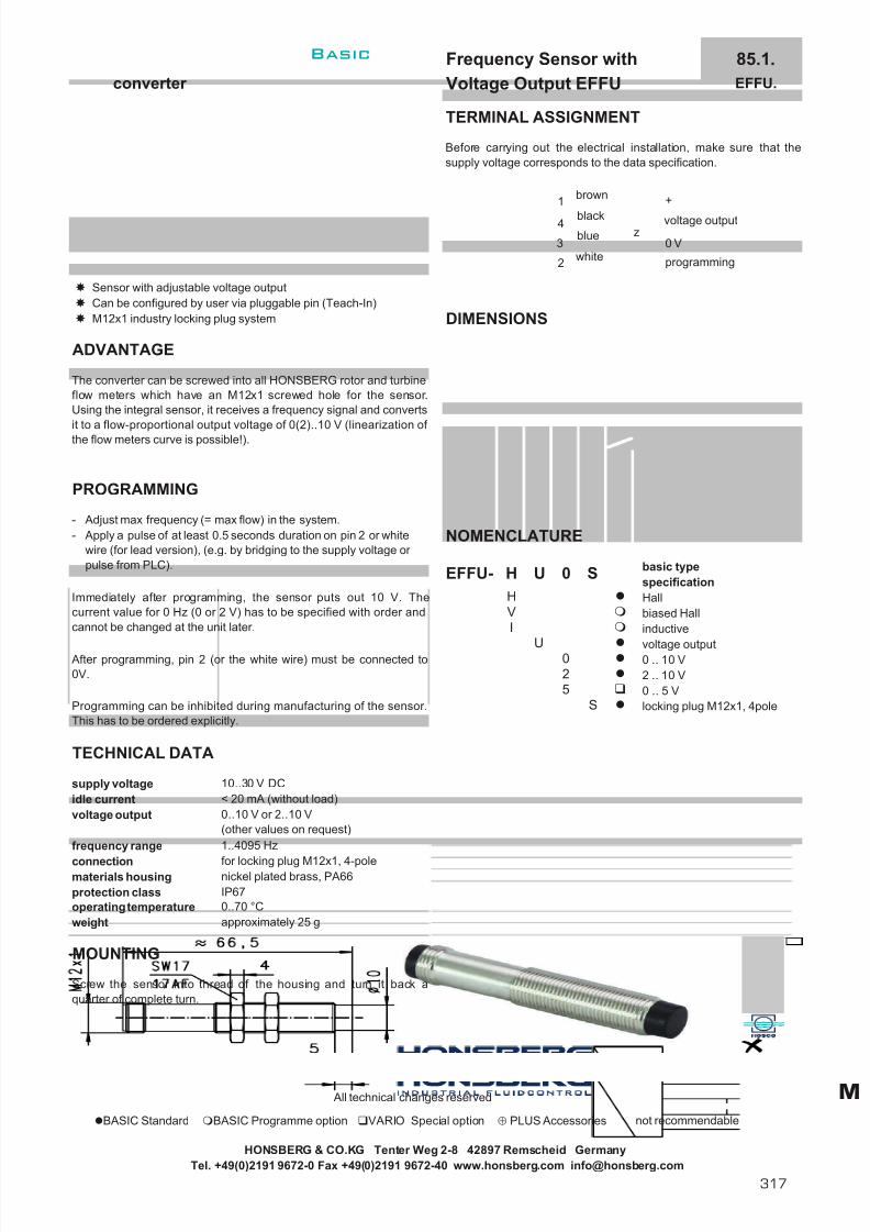
7/22/2019 General Honsberg
http://slidepdf.com/reader/full/general-honsberg 319/347
Frequency Sensor with 85.1.converter Voltage Output EFFU EFFU.
TERMINAL ASSIGNMENT
Sensor with adjustable voltage outputCan be configured by user via pluggable pin (Teach-In)M12x1 industry locking plug system DIMENSIONS
ADVANTAGE
PROGRAMMING
Adjust max frequency (= max flow) in the system.
NOMENCLATURE
basic typespecificationHallbiased Hallinductive
voltage output0 .. 10 V2 .. 10 V0 .. 5 Vlocking plug M12x1, 4pole
TECHNICAL DATA
10..30 V DC< 20 mA (without load)
1..4095 Hz
for locking plug M12x1, 4-polematerials housing nickel plated brass, PA66
IP67operating temperature 0..70 °Cweight approximately 25 g
MOUNTING
All technical changes reserved
BASIC Standard BASIC Programme option VARIO Special option ⊕ PLUS Accessories not recommendable
5
Screw the sensor into thread of the housing and turn it back aquarter of complete turn.
Programming can be inhibited during manufacturing of the sensor.This has to be ordered explicitly.
voltage output 0..10 V or 2..10 V(other values on request)
S
02
U
VI
--
H
EFFU-
idle current
Apply a pulse of at least 0.5 seconds duration on pin 2 or whitewire (for lead version), (e.g. by bridging to the supply voltage or pulse from PLC).
protection class
connection
Immediately after programming, the sensor puts out 10 V. Thecurrent value for 0 Hz (0 or 2 V) has to be specified with order andcannot be changed at the unit later.
After programming, pin 2 (or the white wire) must be connected to0V.
frequency range
The converter can be screwed into all HONSBERG rotor and turbineflow meters which have an M12x1 screwed hole for the sensor.Using the integral sensor, it receives a frequency signal and convertsit to a flow-proportional output voltage of 0(2)..10 V (linearization of the flow meters curve is possible!).
Before carrying out the electrical installation, make sure that thesupply voltage corresponds to the data specification.
supply voltage
H U 0 S
HONSBERG & CO.KG Tenter Weg 2-8 42897 Remscheid GermanyTel. +49(0)2191 9672-0 Fax +49(0)2191 9672-40 www.honsberg.com [email protected]
1
4
3
blackblue z
voltage output
0 V
+brown
2 programmingwhite
Basic
M
317

7/22/2019 General Honsberg
http://slidepdf.com/reader/full/general-honsberg 320/347
Ex-Amplifier 80.1.converter EEV1 / EEV2 EEV.
WIRING DIAGRAM
R1 >1,8k Ω / R2 <100k Ω R intern = 510 Ω
EEV1: Imax = 30 mA EEV2: Imax = 6 mA
ADVANTAGE
ASSEMBLY
DIMENSIONS
TECHNICAL DAT
outer inductance EEx ia IICmax. EEx ib IICouter capacitance EEx ia IICmax. EEx ib IIC
COMBINATION WITH FLOW METERS
product informationRotors 4.2.RRI.
4.2.RRH.4.2.RR.32
Turbines 5.1.RT.Volumetric flow meters 6.1.VHZ.
EEV2 is applicable to NAMUR-sensors only.
All technical changes reserved
IP 30
< 1,4 mA< 7 mA> 14 mA > 2,8 mA
PA66
4 µF 4 µF
The two-channel separation circuit amplifiers with transistor outputserve as an interface between electrical signals from the highlycombustible range (ex area) and the not highly combustible range(non-ex area). The input signals (frequencies or switching signals) of NAMUR- and other 2-wire-sensors, as well as mechanical contactsor opto couplers are transferred to the outputs. The outputs areamong themselves and from the remaining circuit galvanicallyseparated. The electrical circuits of the sensor are galvanicallyconnected with the power supply. The intrinsically safe electriccircuits are suitable for zone 1, 2, 21 and 22.
188 mW 24 mW
6,7 mH 330 mH641 nF
power consumption DCno-load voltage
max. 75 mA max. 9,3 mA
outputs 2x open collector Umax = 30 V AC/DC
3 mH 3 mH
475 nF
Before start-up it is to be guaranteed that the clamp PA is connectedwith the potential equalization of the highly combustible range; whensupplied with a safe galvanic separation the connection of thepotential equalization can be omitted.
EEV1 is applicable to 2-wire-sensors according to DIN EN 60947-5-6, 2-wire-Hall-sensors and floating mechanical contacts or opto-couplers.
connection diameter material housing
max. 10 V DC
24 V AC/DC ±20%3,6 W
EEV1 EEV2
The device is to be assembled onto a hat rail in a switch cabinet or asimilar installation (min. IP20) outside the Ex-zone area.
conformity PTB Nr. Ex-99.E.2073 XCE
operating voltage
short-circuit currentoutput power
actuating signal
-25..+60°Coperating temperature
< 1,5mm² with end-sleeves
HONSBERG & CO.KG Tenter Weg 2-8 42897 Remscheid GermanyTel. +49(0)2191 9672-0 Fax +49(0)2191 9672-40 www.honsberg.com [email protected]
up to a crest value of thenominal voltage of 60 V
galvanic separation
screw terminalselectrical connection
protection IEC 529connectors IP 20
9 2
22 107,5
R2
R1 1
3
6
4
I<0,1mAI>Imax
I<0,1mAI>Imax
S
S
DK
DK
R internal
P
8
11
9
12
7
10
2
24V±20%
AC/DCPA
R internal
Basic
318

7/22/2019 General Honsberg
http://slidepdf.com/reader/full/general-honsberg 321/347
319
Device description
The residual current flow of 100 mAis monitored by an auxiliary circuit. In
the event of a reduction in this current e.g. by a breakage in the control lead,
the output relay is released.
l One- or two-channell Control current circuit
[EEX ia] IIC
Multifunctional relays are mono-stablecontact protectors for connection tosingle contacts.They increase switching safety andcapacity of threshold instruments andreduce their contact load.Unintentional switching of the devicecaused by vibration is significantlyreduced by an off-delay.
l Increases switchingcapacity
l Off-delay
These devices can be programmed by the user to count time or pulses, as aposition display or frequency counterand have two pre-selectable outputs.All the settings, including programming
the pre-selected values, are carriedout using just four keys on the front of
the device and a plain text menu in thedisplay.
l Current flow, filling, batchfilling, difference monitor-ing
l A, B inputs, recognition ofdirection
l Displays [e.g. when coun- ting totals in m² andlitres]
l Simple to usel Factor 0.0001…9.9999l Data storage 10 yearsl Adjustable thresholds [2]l Relay outputs
With the appropriate flow sensors, theESA1 electronic unit forms an adjusta-ble flow switch with trend indicator.When the switching point is undercut
the output changes from 24 V DC to0 V. The switching point can be adju-sted at any time by pressing the“press” key and simultaneously turning
the potentiometer. A red LED indicates
undercutting of the switching point.
l Compact local display andswitching module
l Switching point can befaded in
l Switching point can be set without process condition
WE - Isolating switching amplifier with relay output
MSR - Multifunctional relay
EEZ-904 - Counter
ESA1 - Local electronic unit for frequency generating sensors
M
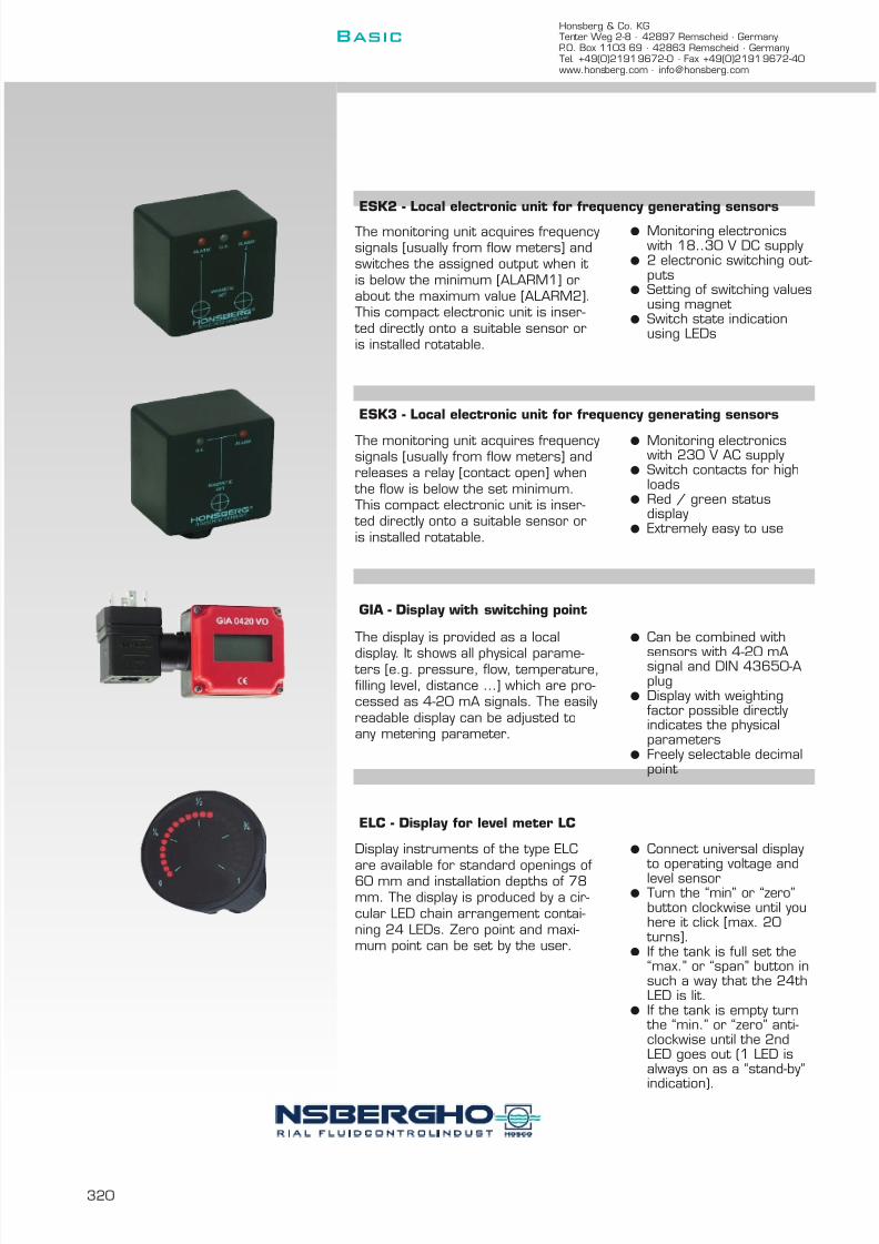
7/22/2019 General Honsberg
http://slidepdf.com/reader/full/general-honsberg 322/347
Honsberg & Co. KGTenter Weg 2-8 · 42897 Remscheid · GermanyP.O. Box 1103 69 · 42863 Remscheid · GermanyTel. +49(0)2191 9672-0 · Fax +49(0)2191 9672-40www.honsberg.com · [email protected]
Basic
320
The monitoring unit acquires frequencysignals [usually from flow meters] andswitches the assigned output when it is below the minimum [ALARM1] orabout the maximum value [ALARM2].This compact electronic unit is inser-
ted directly onto a suitable sensor oris installed rotatable.
l Monitoring electronicswith 18..30 V DC supply
l 2 electronic switching out-puts
l Setting of switching valuesusing magnet
l Switch state indicationusing LEDs
The monitoring unit acquires frequencysignals [usually from flow meters] andreleases a relay [contact open] when
the flow is below the set minimum.This compact electronic unit is inser-
ted directly onto a suitable sensor oris installed rotatable.
l Monitoring electronicswith 230 V AC supply
l Switch contacts for highloads
l Red / green statusdisplay
l Extremely easy to use
The display is provided as a local
display. It shows all physical parame- ters [e.g. pressure, flow, temperature,filling level, distance …] which are pro-cessed as 4-20 mA signals. The easilyreadable display can be adjusted toany metering parameter.
l Can be combined with
sensors with 4-20 mAsignal and DIN 43650-Aplug
l Display with weightingfactor possible directlyindicates the physicalparameters
l Freely selectable decimalpoint
Display instruments of the type ELC
are available for standard openings of60 mm and installation depths of 78mm. The display is produced by a cir-cular LED chain arrangement contai-ning 24 LEDs. Zero point and maxi-mum point can be set by the user.
l Connect universal display
to operating voltage andlevel sensorl Turn the “min” or “zero”
button clockwise until youhere it click [max. 20
turns].l If the tank is full set the
“max.” or “span” button insuch a way that the 24thLED is lit.
l If the tank is empty turn the “min.” or “zero” anti-clockwise until the 2ndLED goes out (1 LED isalways on as a “stand-by”
indication).
ESK2 - Local electronic unit for frequency generating sensors
ESK3 - Local electronic unit for frequency generating sensors
GIA - Display with switching point
ELC - Display for level meter LC

7/22/2019 General Honsberg
http://slidepdf.com/reader/full/general-honsberg 323/347
Filters, accessories
The technology FiltersDirt traps with magnetic separators for dirt protection and separation of ferrite sludge.Extremely fine filtration of liquids.
AccessoriesThe accessories range includes mechanicalcomponents such as valves [VC], valvestrips [VB], fittings [TS] and flanges [FL] orelectrical components as contact protec-
tion [HE].
Application
l Soiling protectionl Regulatingl Contact to pipelinel Contact protection
Contents
System description 322
Device descriptions 323
l Filteringl Regulating

7/22/2019 General Honsberg
http://slidepdf.com/reader/full/general-honsberg 324/347
Honsberg & Co. KGTenter Weg 2-8 · 42897 Remscheid · GermanyP.O. Box 1103 69 · 42863 Remscheid · GermanyTel. +49(0)2191 9672-0 · Fax +49(0)2191 9672-40www.honsberg.com · [email protected]
Basic
322
Filters
Honsberg filters are provided to protect Honsberg devices against soiling or as independent components for coarse and fine filtrationof liquids.
The fine filters [ZE] have filter cartridges in a fineness range from5-250 µm in metal or ceramic and are thus able to take over taskswhich require extremely fine filtration.
A standard dirt trap is only able to achieve part of its protective functionwhere ferrite abrasion is present in the medium, which is much smallerin grain size than the mesh of the dirt trap and is thus rinsed throughit. For such cases, Honsberg magnetic filters [ZV] provide additionalprotection in that a magnetic rod which is equipped with shielded pairsof magnets is positioned in the centre of the dirt trap sieve and precipi-
tates ferrite materials.
The individual pairs of magnets are poled in a certain way and shieldedfrom one another by soft iron discs creating an optimum magnetic fieldin the area of the sieve, thus guaranteeing better efficiency.
The connection of the magnetic rod with the dirt trap cover leads tosimple cleaning of the magnetic rod within the context of the specifiedmaintenance intervals. The application ranges of Honsberg magneticfilters include industrial lubricating and cooling circuits as well as wher-ever the protection of high-quality metering devices such as heat coun-
ters etc. must be guaranteed, such as in the area of heating technologywith boilers and radiators.
Accessories
The accessories range includes mechanical components such as valves[VC], valve strips [VB], fittings [TS] and flanges [FL] or electrical compo-nents as contact protection [HE].

7/22/2019 General Honsberg
http://slidepdf.com/reader/full/general-honsberg 325/347
323
m i s c e
l l a n e o u s
p a g e
g a s
/ a
i r
o i l
w a t e r
m a x . t e m p e r a t u r e
° C
m a x . p r e s s u r e
b a r
c o n n e c t i o n s
t y p e
n o m
i n a
l d i a m e t e r
ZV magnetic filter 15 - 80 female thread bronze 16 150 l l 3 324
ZEK fine filter 4 - 15 female thread plastic 16 150 l l 3 325ZEL fine filter 4 - 15 female thread plastic 16 150 l l 3
ZEG fine filter 10 - 20 female thread plastic 16 150 l l 3
VB manifold 20 female thread aluminium 25 100 l l 327
TS control valves 10 - 50 T-fitting 25 l l l 3 328
VC control valves 4 female thread stainless steel 13 120 l l 3 329
FL flange connection 40-500 welding socket 16 l l l 3 330
HE spark protector 85 323
d i s c r e p t i o n
The reed switches or micro-switches used in Honsberg moni- toring devices have a limited electrical switching capacitywhich can be taken from the descriptions for the individualdevices. With higher switching values or if inductive loads orlong line lengths are involved, a suppression circuit is recom-mended for the reed switch or micro-switch. The typeHE100ZE is available for this purpose.
Principle
Dimensions
Technical data:Capacity 0.047 - 0.47 µFCapacity tolerance ±20%Resistance range 22 - 470 W
Resistance tolerance ±30% Voltage 250 V AC 50 Hz; 630 V DCPeak voltage 1000 V Power 0,5 WOperating temperature max. 85°CApproval S, N, D, Fl, VDE, SEV, ULWeight 0.01 kg
Y compactY economical
f i l t e r
s u p p o r t i n g c o m p o n e n t s
Spark protectorHE100ZB
84.1HE.
l standard m standard option special option all data sheets available under www.honsberg.com
N
Basic
HONSBERG & CO.KG Tenter Weg 2-8 42897 Remscheid GermanyTel. +49(0)2191 9672-0 Fax +49(0)2191 9672-40 www.honsberg.com [email protected]
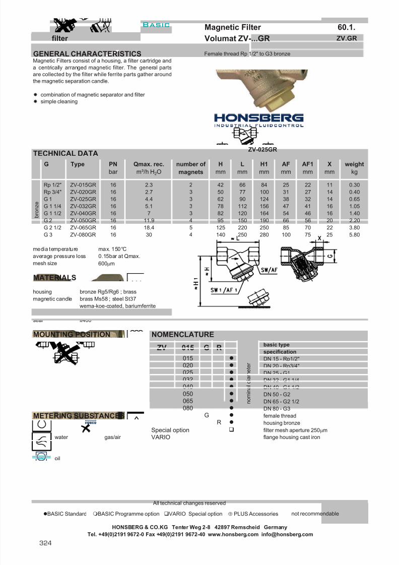
7/22/2019 General Honsberg
http://slidepdf.com/reader/full/general-honsberg 326/347
Magnetic Filter 60.1.filter Volumat ZV-...GR ZV.GR
GENERAL CHARACTERISTICS Female thread Rp 1/2" to G3 bronze
TECHNICAL DATA
media temperature max. 150°Caverage pressure loss 0.15bar at Qmax.mesh size 600 µm
MATERIALS
housing bronze Rg5/Rg6 ; brassmagnetic candle brass Ms58 ; steel St37
wema-koe-coated, bariumferritefilter stainless steel 1.4301seal lt400
MOUNTING POSITION NOMENCLATUREbasic typespecificationDN 15 - Rp1/2"DN 20 - Rp3/4"DN 25 - G1DN 32 - G1 1/4DN 40 - G1 1/2
DN 50 - G2DN 65 - G2 1/2DN 80 - G3
METERING SUBSTANCES female threadhousing bronze
Special option filter mesh aperture 250 µmwater gas/air VARIO flange housing cast iron
oil
All technical changes reserved
BASIC Standard BASIC Programme option VARIO Special option ⊕ PLUS Accessories not recommendable
HONSBERG & CO.KG Tenter Weg 2-8 42897 Remscheid GermanyTel. +49(0)2191 9672-0 Fax +49(0)2191 9672-40 www.honsberg.com [email protected]
5.8075
ZV-015GR
250250 85 22280 100
Type number of magnets
2
ZV-040GRZV-032GRZV-025GRZV-020GR
2.3
16 7
G 3 ZV-080GRZV-065GRZV-050GR
G 1 1/4G 1 1/2G 2G 2 1/2
G
Rp 3/4"Rp 1/2"
G 1
253.807016 18.4 2201255
3016
1.0516
66 56 20 2.201.40
19012082 16415095
0.650.40
16 4.4 9062 38 14323
Xmm
0.3016 2.7 7750 100 27 143
065
025
84 11
54 4641 16
124156
RG
H1mm
AFmm
Lmm
47
AF1mm
25 2231
weightkg
Hmm
11278
42 66
015
5.1
040
050
020
032
PNbar
Qmax. rec.m³/h H 2O
16
b r o n z e
16
4
3
RZV-015
G
16 11.9
140
080
Magnetic Filters consist of a housing, a filter cartridge anda centrically arranged magnetic filter. The general partsare collected by the filter while ferrite parts gather aroundthe magnetic separation candle.
combination of magnetic separator and filter simple cleaning
34
ZV-025GR
n o m i n a l d i a m e t e r
Basic
324

7/22/2019 General Honsberg
http://slidepdf.com/reader/full/general-honsberg 327/347
Fine Filter 61.1.filter Volumat ZE ZE.
GENERAL CHARACTERISTICS Female thread G1/8 to G3/4 PP
TECHNICAL DATA
operational pressure 10 bar at 24°C7 bar at 52°C
operational temperature max. 52°C
MATERIALS
housing PPcap PP or transparent nylonfilter UHMW-PE sintered plastic or stainless steelseal NBR / Viton
HONSBERG & CO.KG Tenter Weg 2-8 42897 Remscheid GermanyTel. +49(0)2191 9672-0 Fax +49(0)2191 9672-40 www.honsberg.com [email protected]
The Fine Filter is fitted with various filter elements in meshsize and material. Filters are emploied for the cleaning of liquids and gases.
filter from 5 µm to 300 µmsimple cleaningtransparent or opaque cups
G
ZEL-008GP....
ZEL-015GP....ZEG-015GP....
G3/4
P P
G1/4
G1/8
G3/8
7553G1/2
116 20ZEG-020GP.... 90 75
0.17520ZEL-010GP....
74ZEG-010GP....ZEK-015GP....
Type
ZEK-004GP....
1948.5
ZEL-004GP....ZEK-008GP....
1919
ZEK-010GP....
Dmm
Xmm
19
1948.548.548.5
0.06019
48.5
48.5
19
0.0700.0650.0851948.5
0.0750.050
weightkg
0.050
Lmm
57.557.57474747490
Hmm
478450835286
114
750.190
48.590
0.0800.17020
7487114
Basic
N325

7/22/2019 General Honsberg
http://slidepdf.com/reader/full/general-honsberg 328/347
Fine Filter 61.1.filter Volumat ZE ZE.
ELECTRICAL DATA
No electrical components.
MOUNTING POSITION METERING SUBSTANCES
water
gas/air
NOMENCLATURE For combinations see table "technical data"
basic typespecificationshort filter Ø 18longer filter Ø 18large filter Ø 28DN 4 - G1/8DN 8 - G1/4DN 10 - G3/8DN 15 - G1/2DN 20 - G3/4female threadhousing PPcap PPcap transparent nylon
5 µm sintered plastic35 µm sintered plastic
80 µm sintered plastic50 µm stainless steel100 µm stainless steel300 µm stainless steelseal NBRseal Viton
All technical changes reserved
BASIC Standard BASIC Programme option VARIO Special option ⊕ PLUS Accessories not recommendable
HONSBERG & CO.KG Tenter Weg 2-8 42897 Remscheid GermanyTel. +49(0)2191 9672-0 Fax +49(0)2191 9672-40 www.honsberg.com [email protected]
PG
015
P
ZEL-ZEG-
ZEK-
004
G
P
N015ZEK-
020
008010
N005
050100
N
P 005
300
035080
V
n o m i n a l
d i a m e t e r
f i l t e r
Basic
326

7/22/2019 General Honsberg
http://slidepdf.com/reader/full/general-honsberg 329/347
Manifold 70.1.accessories Plus VB-...GA/K/M VB.
GENERAL CHARACTERISTICS Female thread G1/2 up tp G3/4 aluminium/brass/stainless steel
Combination with the following flowmeters
NJ-...W... - product information 1.2.NJ.NJV-...W... - product information 1.2.NJV.VO-...W... - product information 1.2.VO.VL-...W... - product information 2.3.VL.
VB-020GA3TECHNICAL DATA mit NJV-015WM
pressure PN 25 bar media temperature max. 110°C
MATERIALS
VB-...GAhousing aluminium anodizedseal NBRwetted parts brass, brass nickel platedexternal parts Al, brass nickel plated
NOMENCLATUREbasic typespecification
nominal diameter DN15 - G1/2nominal diameter DN20 - G3/4female threadaluminiumstainless steel (wetted parts and housing 1.4305)brass (housing Ms58 nickel plated)1-fold port2-fold port3-fold port4-fold port5-fold port6-fold port7-fold port8-fold port
All technical changes reserved
BASIC Standard BASIC Programme option VARIO Special option ⊕ PLUS Accessories not recommendable
HONSBERG & CO.KG Tenter Weg 2-8 42897 Remscheid GermanyTel. +49(0)2191 9672-0 Fax +49(0)2191 9672-40 www.honsberg.com [email protected]
3.878 400 3 185
350 3 160
2.43.03.4
6 300 3 1355 250 2 -
- 1.64 200 2 - 2.13 150 2
- 0.62 100 2 - 1.11 50 2
number of fixing holes Amm
Valve port lenghtmm (without plug)
weightkg (aluminium)
8
M
67
5
34
21
K
G A 1
G
VB- 020
015020
A
Manifold for single or multiple circuits. With integratedneedle valve for manuel flow control.
Attention! Observe nominal pressureand temperature of individual flow metersintalled!
Basic
N327

7/22/2019 General Honsberg
http://slidepdf.com/reader/full/general-honsberg 330/347
connection T-fittings 71.1.accessories Plus TS- TS.
GENERAL CHARACTERISTICS female thread G3/8 to G2 brass/stainless steel
Combination with the following flowmeters
paddle UM3/UR1/UR2/UR3calorimetric EFK… / Flex-F / omni-F
TECHNICAL DATA
pressure PN25
MATERIALSTS-.M… TS-.K…Ms58 nickel plated stainless steel 1.4305
NOMENCLATUREbasic typespecificationT-T-fittingsfor paddle switch (UM/UR)for calorimetric system liquid mediafor calorimetrig system gaseous media (additional plastic)brassstainless steel 1.4305DN 10 - G3/8DN 15 - G1/2DN 20 - G3/4DN 25 - G1DN 32 - G1 1/4DN 40 - G1 1/2DN 50 - G2
All technical changes reserved
BASIC Standard BASIC Programme option VARIO Special option ⊕ PLUS Accessories not recommendable
TS-..025TS-..032
1249 50 12
1237 50 12
1029 50 12
2
50
50
TS-..040TS-..050
50
TS-..015TS-..020
3
TS-
TS-
1
032
1
KM
010
025
010015020
M
050
40
f o r n o m i n a l d i a m e t e
040
Hmm
2828
33
T-fittings to the direct installation in piping with G femalethread in the materials brass or stainless steel.
Lmm
Xmm
50 10
Type
TS-..010
HONSBERG & CO.KG Tenter Weg 2-8 42897 Remscheid GermanyTel. +49(0)2191 9672-0 Fax +49(0)2191 9672-40 www.honsberg.com [email protected]
Basic
328
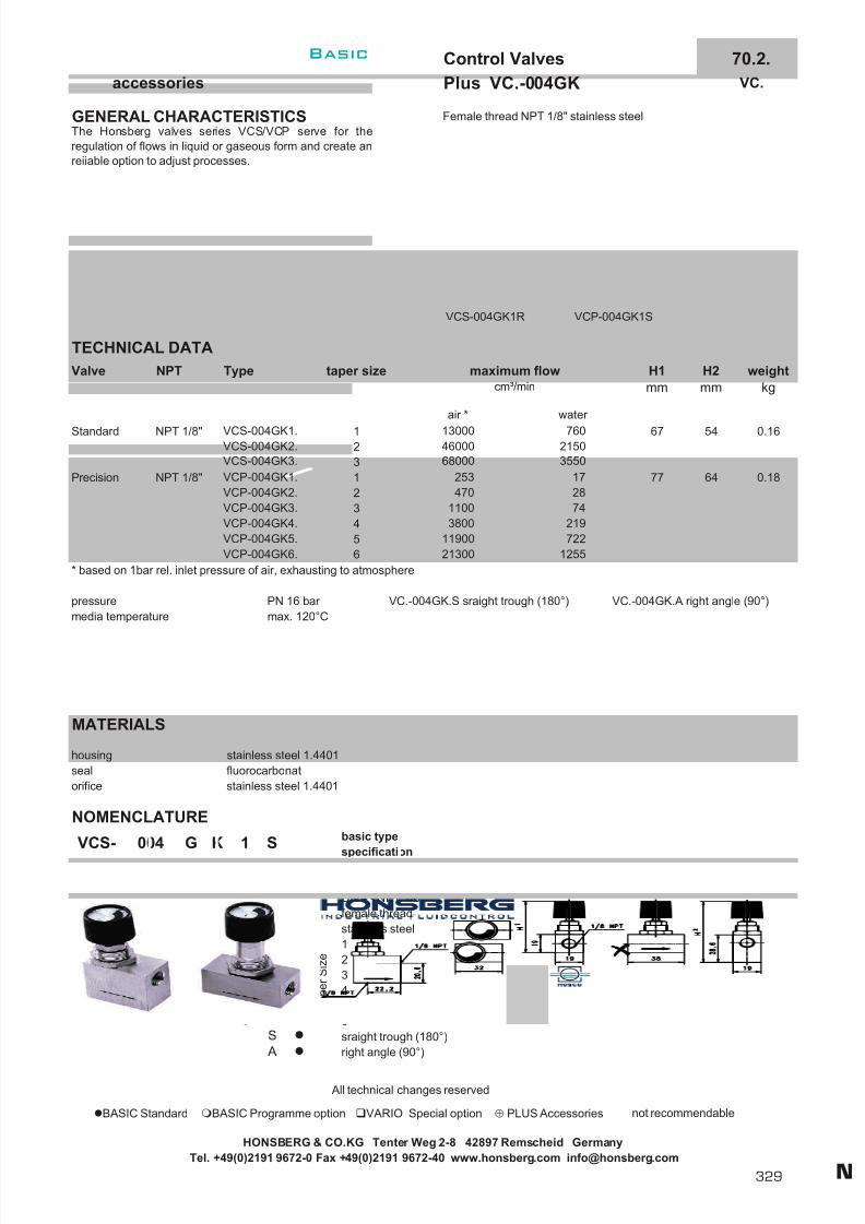
7/22/2019 General Honsberg
http://slidepdf.com/reader/full/general-honsberg 331/347
Control Valves 70.2.accessories Plus VC.-004GK VC.
GENERAL CHARACTERISTICS Female thread NPT 1/8" stainless steel
VCS-004GK1R VCP-004GK1S
TECHNICAL DATA
* based on 1bar rel. inlet pressure of air, exhausting to atmosphere
pressure PN 16 bar VC.-004GK.S sraight trough (180°) VC.-004GK.A right angle (90°)media temperature max. 120°C
MATERIALS
housing stainless steel 1.4401seal fluorocarbonatorifice stainless steel 1.4401
NOMENCLATUREbasic type
specificationstandard valve 9 turns to full openprecision valve 16 turns to full openDN 4 - NPT 1/8"female threadstainless steel123456sraight trough (180°)right angle (90°)
All technical changes reserved
BASIC Standard BASIC Programme option VARIO Special option ⊕ PLUS Accessories not recommendable
Valve
Standard
HONSBERG & CO.KG Tenter Weg 2-8 42897 Remscheid GermanyTel. +49(0)2191 9672-0 Fax +49(0)2191 9672-40 www.honsberg.com [email protected]
NPT 1/8"
NPT Type
VCS-004GK1.VCS-004GK2.
H1mm
67
77 64
54
H2mm
21300
weightkg
0.16
0.18
1255
air *
130004600068000
253470
11003800
11900
A
G
S
T a p e r S i z e
2874
VCP-004GK5.VCP-004GK6.
only VCP-
VCP-004GK2.VCP-004GK3.
6
VCP-004GK4.
2
maximum flowcm³/min
water
31
12
76021503550
17
taper size
5
S
VCS-004GK3.VCP-004GK1.
VCP-VCS-
34
Precision NPT 1/8"
VCS- 004 G K 1
12
K
004
45
3
The Honsberg valves series VCS/VCP serve for theregulation of flows in liquid or gaseous form and create anreiiable option to adjust processes.
219722
6
Basic
N329

7/22/2019 General Honsberg
http://slidepdf.com/reader/full/general-honsberg 332/347
Flange Connection 71.1.accessories Plus FL-032S/K FL.
GENERAL CHARACTERISTICS Flange DN32 steel/stainless steel
Flow Switch VM-...E. - product information 2.1.VM.E
Flowmeter TZ1-...E. - product information 2.3.TZ1.E
TECHNICAL DATA
Flange DIN 2527 PN 16 nominal diameter 32Types of contact faces DIN 2526 Form CSeal Ø82/43x2 Novapress 200Hexagon head screws DIN EN 24017 M16x50-5.6Hexagon nuts DIN EN 24032 M16-5
DN 40-65 DN 80-500
NOMENCLATUREbasic typespecificationmounting flange, welded to connection piece including screw, nut and seal.DN 32steelstainless steelDN 40DN 50DN 65DN 80DN 100DN 125DN 150DN 200DN 250DN 300DN 400DN 500
All technical changes reserved
BASIC Standard BASIC Programme option VARIO Special option ⊕ PLUS Accessories not recommendable
HONSBERG & CO.KG Tenter Weg 2-8 42897 Remscheid GermanyTel. +49(0)2191 9672-0 Fax +49(0)2191 9672-40 www.honsberg.com [email protected]
Mounting flange with weld-on connection piece for suitablymounting flow switches and meters.
H40 65
ØD48.3
6165 76.1 57
60.3
S
065080100
DN
50
040FL- 032
032FL-
K040
f o r n o m i n a l d i a m e t e r
125150
400300
500
250200
050
S
Basic
330

7/22/2019 General Honsberg
http://slidepdf.com/reader/full/general-honsberg 333/347
331
Basis for business
Honsberg as partner ofindustrial plant construction
Independent development, competitive production and a customer-oriented sales philosophy makes Honsberg into a reliable partnerof industrial plant construction and the processing industry. Ourorganisation is certified to ISO 9001/2000, guaranteeing product quality and first-rate processing.
The Honsberg product you are using thus has the best possible pre-conditions for fulfilling its planned metering andmonitoring task reliably over a long service life.
Assembly
Design using 3D-CAD
Milling centre in the mechanical production
Metering machineEuropean approvalfor electronic safety

7/22/2019 General Honsberg
http://slidepdf.com/reader/full/general-honsberg 334/347
332
Honsberg & Co. KGTenter Weg 2-8 · 42897 Remscheid · GermanyP.O. Box 1103 69 · 42863 Remscheid · GermanyTel. +49(0)2191 9672-0 · Fax +49(0)2191 9672-40www.honsberg.com · [email protected]
Basic
Quality
General principlesA high and constant standard of quality is an important pre-requisitefor a partner of industrial plant construction in sometimes safety-related applications. These requirements are implicated by Honsbergas follows:
l ISO 9000/2001 approvall Independent QA organisationl Regular auditing by independent institutesl Regular internal training events and updating of workflowsl Regular auditing of our A-suppliersl Traceability and electronic data archiving of the products
delivered
Individual testing
Every order we are entrusted with is tested and released individuallyon the basis of the order data before dispatch.
Flow0.01-5000 l/min
Level20-2000 mm
Temperature-40 … +250 °C
Pressure-1 … +400 bar
System-related design
On account of operative requirements Honsberg units are optimised asearly as the design stage and their basic function adapted to the task on hand.
l Pressure loss dependent on Qmaxl Hysteresis selection possiblel Max. flow quantities 2-3 m/sl Tolerance 1-5%l Repetition accuracy 1%

7/22/2019 General Honsberg
http://slidepdf.com/reader/full/general-honsberg 335/347
333
Approvals
Honsberg devices are handed over to reliable dispatch partnersfollowing a 100 % test and professional packaging for delivery
to customers.
There are detailed instructions for initial operation included withevery device system.
Warranty and service conditions can be found in our General Termsof Sale and the conditions of the Central Association of the GermanElectro-Industry [ZVEI] in the respective valid version.
Services include
l Support during initial operationl Repair or replacement l Application advice
Service telephone:Tel.: +49 (0) 2191 / 9672-22
ATEX GL TÜV
DIN-GOST KTA

7/22/2019 General Honsberg
http://slidepdf.com/reader/full/general-honsberg 336/347
334
Honsberg & Co. KGTenter Weg 2-8 · 42897 Remscheid · GermanyP.O. Box 1103 69 · 42863 Remscheid · GermanyTel. +49(0)2191 9672-0 · Fax +49(0)2191 9672-40www.honsberg.com · [email protected]
Basic
Safety first
Planning data for installation
Device description
l Monitor - switching device
l Pointer - local or remote display in an accuracy range from 5 %
l Meter - local metering unit or continuous and linear signalgeneration in an accuracy range of up to 5 %
The device function
l Measured value - current display
l Final value - maximum display / switching valuel Tolerance
Tolerance is the extent of the deviation of a parameter from thenormal status or normal dimension. Tolerance specifications aregiven within the context of the device description and can fluctu-ate under application conditions.
l Repeating accuracy - deviation during permanent function
l Metering rangeThe metering range describes the operative spread within which
the device can be used. This can be the adjustment range for
the switching point or the display range of a metering unit. Weaim to make this spread as large as possible to extend the poss-ibilities of each individual device. The working range is usually thefactor 1:10 e.g. 10-100 l/min.
l Flow rateMechanical and electronic flow meters are designed for a cer-
tain flow rate or flow speed. We specify these data with a rec-ommendation for a maximum flow speed in the area of 2-3m/sec. or according to individual specifications for the respec-
tive product group. The maximum recommended flow rate canbe exceeded. In this case increased pressure loss or heaviermaterial wear must be expected.
l HysteresisThe switching difference with switching devices and the displaydifference with display devices represent important operatingdata for the function of metering devices. The switching differ-ence defines the difference between the switch-on and switch-offpoints with increasing or decreasing flow rate. This difference
value is determined by the switching characteristic or themechanical function of the metering unit. In the case of switch-ing devices it must be ensured that the switch-on point isreached as a pre-condition for the contact function. In the caseof display instruments there is a difference in display withincreasing and decreasing flow rate.
Example:
Switch-off end 4.2 l/min
Tolerance ±0.3 l/min
Hysteresis 0.5 l/min
Functional amount = 4.2 + 0.3+ 0.5 l/min= 5.0 l/min
Qmin. = 5 l/min+ 20 % safety= 6l/min
Flow speed
Interior diameter of pipe in mm
min. switch-off point
minimum pump capacity
20% safety
max. switch-on point incl.tolerances
switching hysteresis
max. switch-off point
switch-off point tolerance

7/22/2019 General Honsberg
http://slidepdf.com/reader/full/general-honsberg 337/347
335
l Direction of flow
The direction of flow must be observed, and is marked on everydevice.
l Settling rangeThe minimum length of the settling ranges depends on therespective application case. Basically, greater settling rangesare required when elbows or fittings are built into the intakeside. Settling ranges of 5xDN are recommended.
l Pressure lossThe term pressure loss describes the drop in pressure cau-sed by the device itself. This value depends largely on
the device design. It is important that the system pressureis above the value of pressure loss in order to guaranteecomponent function. The pressure loss values have been cal-culated on the basis of a flow speed of 2 m/sec. When thisfigure is exceeded, pressure loss increases disproportionately.
Electrical details
l Make contact - opened when at rest l Break contact - closed when at rest l Changeover contact - make and break contact l Output- [0]4..20 mA, 0..10 V, PNP and/or NPN
And finally …
Initial operation
Certain basic principles must be taken into account during initialmechanical operation and electrical wiring. These are applicablefor all HONSBERG products.
(1) Pressure data must be observed according to devicespecification, as must the temperature range.
(2) During installation, make sure the direction of flow is in thedirection of the arrow symbol.
(3) Straight stretches before and after the devices are benefi-cial to the device function in the sense of a laminar flowprofile.
(4) The circuit can either be seen on the device label ordescribed in the delivery papers. In unfavourable cases[e.g. inductive or capacitive load], plan protective wiring
(5) Clean the pipework system before installation. If permanent soiling occurs, use a magnetic filter [HONSBERG Volumat]or a dirt trap.
Customer service and sales officeTel. +49 (0) 2191/9672-0
Pressure lossD p 1 bar
HONSBERGflow meter / monitor

7/22/2019 General Honsberg
http://slidepdf.com/reader/full/general-honsberg 338/347
Honsberg & Co. KGTenter Weg 2-8 · 42897 Remscheid · GermanyP.O. Box 1103 69 · 42863 Remscheid · GermanyTel. +49(0)2191 9672-0 · Fax +49(0)2191 9672-40www.honsberg.com · [email protected]
Basic
336
The substance is the objective
Viscosity / air / gas / temperature
all data are appoximate values
Operation H 2 O oil viscosity air / gas
100mm²/s 200mm²/s 1 bar air
40 - 99%piston 100% see page 15 + 49 3500%
float 100% special scaling special scaling special scaling
paddle 100% 70 - 80% 1500%see page 115
rotor 100%Oils to 10 mm²/s on request
80%
turbine 100% Oils to 15 mm²/s on request80%
gear wheel,100% 100% 100%
notoval wheel recommendable
calorimetric 100% on request on request on request
magnetic inductiv 100% prohibitive prohibitive prohibitive
level 100% depending of liquid density prohibitive
temperature independent of media
pressure independent of media

7/22/2019 General Honsberg
http://slidepdf.com/reader/full/general-honsberg 339/347
Viscosity
337
Switch point modification refer-ming to viscosity and flow
velocity
Switch point, modification refer-ming to viscosity
TemperatureSwitch point modificationreferming to temperature.
Function piston, viscosity compensated
Function gear- oval wheel, viscosity-independently
brass cast iron cast steel stainless steel stainless steel measuring materialbronze V2A V4A
- - - 0 0 acetic acid- + + + + acetone
+ + + + + alcohol0 + + + + alkalis- - - + + butyric acid+ O O + + carbonic acid0 0 0 0 0 chlorine+ + + + + common salt- 0 0 + + distilled water- - - + + glyceric acid- - - - + hydrochloric acid+ + + + - lime water+ + + + + mineral oil+ + + + + natural gas
+ + + + + paraffin+ + + + + petrol+ + + - + steam- - - + - sulphuric acid
Material stability
+ good O Sufficient - unsifficing
Function piston standard

7/22/2019 General Honsberg
http://slidepdf.com/reader/full/general-honsberg 340/347
338
Honsberg & Co. KGTenter Weg 2-8 · 42897 Remscheid · GermanyP.O. Box 1103 69 · 42863 Remscheid · GermanyTel. +49(0)2191 9672-0 · Fax +49(0)2191 9672-40www.honsberg.com · [email protected]
Basic
The basics are right
Materials
Material selection is divided into 3 classes:
1. wetted and pressurized
2. wetted non pressurized
3. neither wetted nor pressurized
The standard materials are
Special options
The above device descriptions have conveyed a wide range of data and technical possibilities. If you have decided in favour of a HONSBERGproduct, our team is ready to process your order reliably.
Otherwise we recommend contacting HONSBERG for individual adviceand project assistance within the context of the VARIO programmesegment. Please let us have information about your case of applicationand the task to be solved.
Class1 2 3
l Brass l Brass l Brassl Stainless steel l Stainless steel l Stainless steell Plastic l Plastic l Plasticl Red bronze l Bronze l Steell Cast iron l Copper l Casting compoundl Cast steel l Magnetic materials l Copperl Glass l Magnetic materialsl Copper l Glassl Sealing materials l Elastomers
Mechanics Electrics Function
l Pressure stage up to 500 bar
l Special threadl Special flangel Special materialsl
Coating of the partsin contact withmedia
l Damping of movingparts (with air andgases)
l Specified swit-ching differences
l Contact protectionl Special plugl Temperature-resi-
stant cablel Gold-coating for
contacts
l Version forspecified meteringmaterials
l Selected switchingfunction
l Multi-function(integrated flow, temperature, pres-sure monitoringand metering)

7/22/2019 General Honsberg
http://slidepdf.com/reader/full/general-honsberg 341/347
339
Art of combination
The ideaHermetical separation of primary measured value acquisitionand secondary measured value evaluation.
he
rmetical
separation
Primary measured Secondary measured value acquisition value evaluation
Piston Reed switch
Float Micro-switchPaddle Hall sensor
Rotor Inductive proximityswitch
Turbine Optical sensor
Gear wheel Metering unit
Oval wheel Temperature sensor
Flap Bimetal
Sphere Pressure sensor
The advantages
l Optimal matching of mechanical and electrical componentsl Non-contact triggering of contacts and sensorsl Hermetic separation of mechanical and electrical components

7/22/2019 General Honsberg
http://slidepdf.com/reader/full/general-honsberg 342/347
340
Honsberg & Co. KGTenter Weg 2-8 · 42897 Remscheid · GermanyP.O. Box 1103 69 · 42863 Remscheid · GermanyTel. +49(0)2191 9672-0 · Fax +49(0)2191 9672-40www.honsberg.com · [email protected]
Basic
The team is our strenght
Honsbergstaff structure
1. productive2. technical administration3. commercial administration
Honsbergperiode of service(years)
1. 15+2. 10+3. 5+4. < 5 +
Honsbergage structure
1. - 30 Jahre2. - 40 Jahre3. - 50 Jahre4. >50 Jahre
HonsbergClub 15
Team of staff members15 years and more.Appreciation & respect

7/22/2019 General Honsberg
http://slidepdf.com/reader/full/general-honsberg 343/347
341
Communication basics
The Honsberg documentation system
Range summary,company profile31 pages
Application-related devicedescriptions 12 to 24 pages
Informative magazine forcustomers and friends of
the company. Is distributedat irregular intervals.
All catalogues plusprice information
Updated product descriptions, newproducts and applications available asa CD or via the Internet underwww.honsberg.com
Product cataloguesIntegrated systemsOmni 40 pagesFlex 16 pages
Complete range catalogue
344 pagesPrice list 40 pagesView
Focus
Digital
Basic
Omni Flex
Contact
Doku

7/22/2019 General Honsberg
http://slidepdf.com/reader/full/general-honsberg 344/347
342
Honsberg & Co. KGTenter Weg 2-8 · 42897 Remscheid · GermanyP.O. Box 1103 69 · 42863 Remscheid · GermanyTel. +49(0)2191 9672-0 · Fax +49(0)2191 9672-40www.honsberg.com · [email protected]
Basic
Data + details
flow1 l/min = 0.06 m 3/h1 l/min = 0.21997 UK gal/min1 l/min = 0.26420 US gal/min1 m3/h = 16.6667 l/min1 UK gal/min = 4.546 l/min1 US gal/min = 3.785 l/min
length1 feet = 0.304799 m1 feet = 12 inch1 inch = 0.08333 feet 1 inch = 25.39996 mm1 km = 1000 m1 km = 0.53960 naut.mile1 km = 0.62140 stat. mile1 m = 3.28085 feet 1 m = 0.001 km1 m = 1000 mm1 m = 1 .09362 yard1 mm = 0.03937 inch1 mm = 0.001 m1 naut.mile = 1.853 km1 stat. mile = 1.609 km1 yard = 0.91440 km
speed1 ft/s = 0.59252 knot 1 ft/s = 0.30480 m/s1 ft/s = 0.68595 mile/h1 knot = 1.15767 mile/h1 knot = 1.68770 ft/s
1 knot = 0.51441 m/s1 m/s = 3.28084 ft/s1 m/s = 1.94397 knot 1 m/s = 2.25048 mile/h1 mile/h = 1.45784 ft/s1 mile/h = 0.86380 knot 1 mile/h = 0.44435 m/s
pressure1 bar = 100000 Pa1 bar = 14.504 psi1 N/m 2 = 1 Pa1 Pa = 0.00001 bar1 Pa = 1 N/m 2
1 psi = 0.069 bar
volume1 cm 3 = 1000 mm 3
1 dm 3 = 1000 cm 3
1 dm 3 = 1 l1 ft 3 = 1728 in 3
1 ft 3 = 6.2282 UK gal1 ft 3 = 7.4797 US gal1 ft 3 = 0.02832 m 3
1 ft 3 = 28.3169 l1 l = 1 dm 3
1 l = 0.03531 ft 3
1 l = 0.21995 UK gal1 l = 0.26414 US gal1 m 3 = 1000 dm 3
1 m 3 = 35.3146 ft 3
1 UK gal = 0.16056 ft 3
1 UK gal = 4.54656 l1 US gal = 0.1337 ft 3
1 US gal = 3.78583 l
temperature temperature °C = temperature °F - 321.8 temperature °F = temperature °C x 1.8 + 32
weight0.1 kg = 3.53 oz = O lb 3 oz0.2 kg = 7.05 oz = O lb 7 oz0.5 kg = 17.64 oz = 1 Ib 1 oz1.0 kg = 35.27 oz = 2 lb 3 oz2.0 kg = 70.54 oz = 4 lb 6 oz5.0 kg = 176.35 oz = 11 Ib 0 oz
mm 2 /s °E Rl sec S. U.sec sec
1,0 1,0 28,5 -1,5 1,06 30 -2,0 1,12 31 32,62,5 1,17 32 34,43,0 1,22 33 363,5 1,26 34,5 37,64,0 1,3 35,5 39,1
4,5 1,35 37 40,75,0 1,4 38 42,35,5 1,44 39,5 43,96,0 1,48 41 45,56,5 1,52 42 47,17,0 1,56 43,5 48,78,0 1,65 46 52
10,0 1,83 52 58,811,0 1,93 55 62,313,0 2,12 61 69,615,0 2,32 68 77,217,0 2,55 75 85,120,0 2,9 86 97,522,0 3,1 93 10625,0 3,45 105 118,930,0 4,1 125 140,935,0 4,7 144 163,240,0 5,35 164 185,745,0 6,0 185 208,450,0 6,65 205 231,456,0 7,4 229 25960,0 7,9 245 277,470,0 9,24 283,5 323,480,0 10,56 324 369,690,0 11,88 364,5 415,8
100,0 13,2 405 462114,0 15 460,5 526,7150,0 19,8 611 701227,4 30 921 1053,3303,2 40 1228 1404,4379,0 50 1535 1755,5
400,0 52,8 1620 18481080,0 142,5 4435 50002160,0 285 8870 100008460,0 1140 35480 40000
all information beyond our responisibilty
Viscosity
r a n g e g e a r w
h e e
l / o v a
l w h e e
l
r a n g e p
i s t o n
/ p a
d d l e

7/22/2019 General Honsberg
http://slidepdf.com/reader/full/general-honsberg 345/347343
Data + details
materialsstainless steelNo. materials VA AISI BS
1.4122 X 35 CrMo 17 2 - -1.4301 X 5 CrNi 18 10 2 304 304S151.4305 X 10 CrNiS 18 9 2 303 303S211.4310 X 12 CrNi 17 7 2 301 -1.4404 X 2 CrNiMo 17 12 4 316L 316S121.4408 G-X 6 CrNiMo 18 10 - CF-8M -1.4436 X 5 CrNiMo 17 13 4 316 316S161.4462 X 2 CrNiMoN 22 5 - 2205 -1.4541 X 6 CrNiTi 18 11 2 321 321 S1 2
brassNo. materials Ms DIN-EN
2.0230 CuZn1O Ms90 CW 501 L2.0321 CuZn37 Ms63 CW 508 L2.0360 CuZn40 Ms60 CW 509 L2.0380 CuZn39Pb2 Ms59 CW 612 N2.0402 CuZn40Pb2 Ms58 CW 617 N
cast ironNo. materials
0.6026 GG-25
bronzeNo. materials Rg
2.1096.01 G-CuSn5ZnPb Rg52.1093.01 G-CuSn6ZnNi Rg6
cast steelNo. materials GP
1.0619 N GSC-25 GP 240 GH
plastic
ABS acrylicnitrile/butadiene/styrenePA polyamidePC polycarbonat POM polyoxymethylenePP polypropylenPS polystorolPTFE polytetrafluorineethylene (teflon)PVC polyvinyl chloridePVDF polyvinylidenfluoride
elast
DIN/ISO ATSM marking commercial nameCR CR chloroprene-caoutchouc neopren, baypren, butaclor, denka chloropreneEPDM EPDM ethylene-propylene-diene-caoutchouc dutral, keltran, vistalon, nordel, epsyn, buna APFPM FKM fluorine-caoutchouc viton, flureol, tecnoflon, noxtiteNBR NBR acrylicnitrile-butadiene-caoutchouc perbunan, buna N, hycar, breon, butakon

7/22/2019 General Honsberg
http://slidepdf.com/reader/full/general-honsberg 346/347
Honsberg & Co. KGTenter Weg 2-8 · 42897 Remscheid · GermanyP.O. Box 1103 69 · 42863 Remscheid · GermanyTel. +49(0)2191 9672-0 · Fax +49(0)2191 9672-40www.honsberg.com · [email protected]
Basic
344
flowlevel
temperaturepressure
Index
AR 96BL 233CF 220CM2K 146CRG 148CWE 260EDP1 292EEFK 215EEV 318EEZ 319EFFF 316EFFI 315EFFS 314EFFU 317EFK2 210EFKM 208EFKP 208EFKS 215ELC 320EPS 288EPS1 290ESA1 319ESK2 320ESK3 320ETS 274ETSD 276
FF 20FH 226FIS 217FK 230FL 330Flex 297Flex-FIN 212FM 22FQ 231FR 167FW1 56FW3 58FX 59
G 24GIA 320GK 118GKL 121GR 102HD1K 61HD2K 64HE 323HM1K 67HR1MV 70HV 183KH 238KM 239LC 254MD 286MF-003 73MF-007 74MH 88
MI 96MMF 124MP 40MR 75MR1K 77MSR 319MW3 258MWI 261MXM 37MXO 37MXR 36NA 264NB 264NBS 263NG 262NH1 81NJ 82NJV 85NL 265NM 248NMS 249NO 94NR 252NW1 259NW3 258Omni 297
ON 227OT 96OW 228PD 47PH 282PI 284PM 282PO 166PS 287RA 170RH 172RM 168RO 184
RR.-032 180RRF 185RRH-010/025 176RRI-010/025 174RRO-010/025 178RRT 187RRT1 188RS 167RT 190RVM 79RW 256RWI 257SB 250SK 232TF1 272TR 273TS 328TX 38
TZ1-...E 152TZ1-…F 48TZ1-…GK 44TZ1-…GR 42UB1 144UI 141UK-020 106UK-040 108UK-044 110UK-047 112UK-048 114UK-050 116UM3K-…GK 136UM3K-…GM 136UM3K-…VK 138UM3K-…VM 138UR1-…GK 140UR1-…GM 140UR1-…VK 142UR1-…VM 142UR2-…GK 140UR2-…GM 140UR2-…VK 142UR2-…VM 142UR3K-…GK 132UR3K-…GM 132
UR3K-…VK 134UR3K-…VM 134UZ 154
VB 327 VC 329 VD-…F 47 VD-…GK 28 VD-…GR 26 VDO 34 VF 90 VHO 196 VHZ 192 VI 48
VL 104 VM-…E 150 VM-…F 47 VM-…GK 32 VM-…GR 30 VO 92 VP 285WE 319WK 240WO1 229WP 241WR1 169WT 242
XF 157 YR 149ZE 325ZV 324

7/22/2019 General Honsberg
http://slidepdf.com/reader/full/general-honsberg 347/347
Honsberg world wide
The descri p tion of our sales organisation is a vailable under www.honsberg.com/contact
All up -to-date prod uct information is a vailable as PDF files on our webside www.honsberg.com