Embed Size (px)
Citation preview
Roof Deck Design Guide • V1.0 1www.ascsd.com
1.0 GENERAL INFORMATION 1.1 Introduction to ASC Steel Deck . . . . . . . . . . . . . . . . . . . 2-31.2 Panel Features and Benefits . . . . . . . . . . . . . . . . . . . . . 4-71.3 Product Offer . . . . . . . . . . . . . . . . . . . . . . . . . . . . . . . . . 8-101.4 Product Approvals. . . . . . . . . . . . . . . . . . . . . . . . . . . . . . . 111.5 Fire Ratings . . . . . . . . . . . . . . . . . . . . . . . . . . . . . . . . . 12-151.6 Section Properties . . . . . . . . . . . . . . . . . . . . . . . . . . . . 16-171.7 Out of Plane Vertical Loads . . . . . . . . . . . . . . . . . . . . 18-191.8 Web Crippling. . . . . . . . . . . . . . . . . . . . . . . . . . . . . . . . 20-211.9 In Plane Diaphragm Shear . . . . . . . . . . . . . . . . . . . . . 22-231.10 In Plane Diaphragm Flexibility . . . . . . . . . . . . . . . . . . 24-251.11 Support Fastening . . . . . . . . . . . . . . . . . . . . . . . . . . . . 26-311.12 Side Seam Fastening . . . . . . . . . . . . . . . . . . . . . . . . . . 32-331.13 Accessories . . . . . . . . . . . . . . . . . . . . . . . . . . . . . . . . . 34-35
2.0 Acustadek®
2.1 Introduction . . . . . . . . . . . . . . . . . . . . . . . . . . . . . . . . . 36-372.2 Sound Absorption Data . . . . . . . . . . . . . . . . . . . . . . . 38-39
Metric Conversion Chart . . . . . . . . . . . . . . . . . . . . . . . . .62
Table of Contents
ASC Steel Deck is leading the way in innovation with ongoing testing of our profiles. As a result, the printed catalog may not contain/reflect the latest test results and values of our products. For the most current load tables, refer to the IAPMO ER-161 report online at www.ascsd.com.
Your Feedback is WelcomeLeading the way in steel deck innovation is dependent upon your feedback. We invite architects, engineers, building owners, and all members of the building design and construction industry to reach out to ASC Steel Deck with any comments, suggestions, or needs for a profile we currently do not offer
Email us at [email protected]
Hilti is a registered trademark of Hilti Corp., LI- 9494 Schaan, Principality of Liechtenstein
PNEUTEK is a registered trademark of Pneutek, 17 Friars Drive Hudson, NH
www.ascsd.com2 V1.0 • Roof Deck Design Guide
1.1 Introduction
General Benefits of SteelThe many benefits of ASC Steel Deck profiles combine to make one of the most versatile and cost efficient building materials available today. The structural strength of steel deck, relative to its light weight and shear strength, make it the clear building material of choice when compared to wood frame construction. The versatility, recyclable content, structural performance, and ease of installation make steel deck the ideal building material for architects, building owners, and engineers.
Evolution of Company ASC Steel Deck has provided structural steel roof and floor deck throughout the Western United States since the 1970s. Over this time, ASC Steel Deck has undergone a few ownership changes and operated under different business names (ASC Pacific, BHP Steel Building Products, and IMSA Building Products). Since 2002, however, we have operated under the name ASC Steel Deck, a division of ASC Profiles LLC. While the name of the company has changed over the years, our continuous dedication to product innovation, high quality steel deck products, and customer service has positioned ASC Steel Deck as a leader in the industry.
Offering a Full Line of Steel Deck ProductsASC Steel Deck is the only steel deck manufacturer on the West Coast which offers a full line of light-gage structural and deep deck products. From the typical 1½” to 3” roof and composite floor deck, to concrete form deck, to long spanning deep deck profiles, ASC Steel Deck’s extensive product offer meets the needs of the most complex conditions and demands for structural performance and design. Most of our roof deck products are offered in a variety of acoustical and perforated options.
ASC Steel Deck
Roof Deck Design Guide • V1.0 3www.ascsd.com
Introduction 1.1
Aesthetic Value of Steel DeckASC Steel Deck products offer the beauty of exposed steel as an added benefit to the structural performance required of building designs. Our new Smooth Series™ cellular deck offers a blemish free beam-to-pan rivet attachment, providing a clean surface ideal for an exposed steel design. When noise reduction is a necessity, ASC Steel Deck's Acustadek® panels offer acoustical noise reduction capabilities with aesthetic features which complement its use on exposed applications. Acustadek® is generally preferred in high noise areas such as airports, schools, gymnasiums, and concert halls. Acustadek® can contribute to LEED v4 EQ Credit Acoustic Performance Option 2.
Industry InnovatorASC Steel Deck strives to lead the way in providing innovative products that reduce installation costs while offering some of the highest diaphragm shear values in the market today. ASC Steel Deck was an early innovator of the mechanical side-seam attachment method with the introduction of the DeltaGrip® tool in 2003. First to market in 2009, our 36/7/4 attachment pattern provides the lowest installed value in the market using 11⁄2" deep roof deck and has since replaced the previous industry standard 36/5 and 36/7 attachment patterns. Other innovations include N-32, a 32" wide 3" deep roof deck panel, and our new Smooth Series™ rivet attachment for our portfolio of cellular deck products. First to the West Coast market, our new Smooth Series rivet attachment offers a blemish free attachment solution, eliminating the need for field touch up. Each of these innovations and future product offerings are designed to offer the lowest installed cost at the highest level of performance for building owners.
www.ascsd.com4 V1.0 • Roof Deck Design Guide
1.2 Panel Features and Benefits
1½ ” depth, 36” coverage, 5’ to 12’ Optimal Span(s)Excellent Diaphragm ShearWeb and Total Perforated Acustadek® Options DeltaGrip produces the highest shear diaphragms in
the industry for 1½” decks Highest shear lowest cost 36/7/4 attachment pattern
in industry Published tables for welded, pinned, and screw
attachments to supports
1½ ” depth, 36” coverage, 5’ to 12’ Optimal Span(s)Good Diaphragm ShearNo Acustadek® Option Nestable configuration for screwed side lap
attachment Meets Steel Deck Institute SDI wide rib requirements
3 ” depth, 32” coverage, 10’ to 16’ Optimal Span(s)Good Diaphragm ShearWeb and Total Perforated Acustadek® Options DeltaGrip produces the highest shear diaphragms in
the industry for 3 inch decks Wider 32” panel results in the most labor efficient 3”
N Deck in the industry Lightest weight 3” N deck per square foot in the
industry
3” depth, 32” coverage, 10’ to 16’ Optimal Span(s)Modest Diaphragm ShearNo Acustadek® Option Nestable configuration for screwed side lap
attachment Replaces Steel Deck Institute SDI Deep Rib (DR)
roof decks
DGB-36/B-36 DGN-32/N-32®
NN-32™ NESTABLEBN-36 NESTABLE
1½ ” depth, 36” coverage, 8’ to 14’ Optimal Span(s)Excellent Diaphragm ShearPan Perforated Acustadek® Option (Available with Smooth Series™ rivet attachments or welded) Aesthetic flat pan undersideLonger Spanning than non-cellular profile DeltaGrip side-lap attachment provides the same
benefits as non-cellular
3” depth, 32” coverage, 14’ to 20’ Optimal Span(s)Good Diaphragm ShearPan Perforated Acustadek® Option (Available with Smooth Series™ rivet attachments or welded) Aesthetic flat pan undersideLonger Spanning than non-cellular profile DeltaGrip side-lap attachment provides the same
benefits as non-cellular
DGBF-36/BF-36 DGNF-32/NF-32
ASC Steel Deck
Roof Deck Design Guide • V1.0 5www.ascsd.com
Panel Features and Benefits 1.2
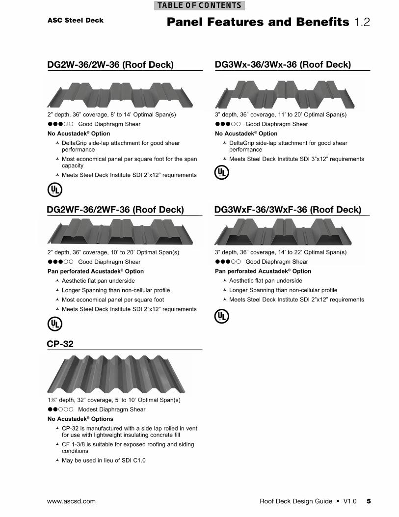
2” depth, 36” coverage, 8’ to 14’ Optimal Span(s)Good Diaphragm ShearNo Acustadek® Option DeltaGrip side-lap attachment for good shear
performance Most economical panel per square foot for the span
capacity Meets Steel Deck Institute SDI 2”x12” requirements
2” depth, 36” coverage, 10’ to 20’ Optimal Span(s)Good Diaphragm ShearPan perforated Acustadek® Option Aesthetic flat pan underside Longer Spanning than non-cellular profile Most economical panel per square foot Meets Steel Deck Institute SDI 2”x12” requirements
13⁄8” depth, 32” coverage, 5’ to 10’ Optimal Span(s)Modest Diaphragm ShearNo Acustadek® Options CP-32 is manufactured with a side lap rolled in vent
for use with lightweight insulating concrete fill CF 1-3/8 is suitable for exposed roofing and siding
conditions May be used in lieu of SDI C1.0
3” depth, 36” coverage, 11’ to 20’ Optimal Span(s)Good Diaphragm ShearNo Acustadek® Option DeltaGrip side-lap attachment for good shear
performance Meets Steel Deck Institute SDI 3”x12” requirements
3” depth, 36” coverage, 14’ to 22’ Optimal Span(s)Good Diaphragm ShearPan perforated Acustadek® Option Aesthetic flat pan underside Longer Spanning than non-cellular profile Meets Steel Deck Institute SDI 2”x12” requirements
DG2WF-36/2WF-36 (Roof Deck)
CP-32
DG3WxF-36/3WxF-36 (Roof Deck)
DG2W-36/2W-36 (Roof Deck) DG3Wx-36/3Wx-36 (Roof Deck)
www.ascsd.com6 V1.0 • Roof Deck Design Guide
1.2 Panel Features and Benefits
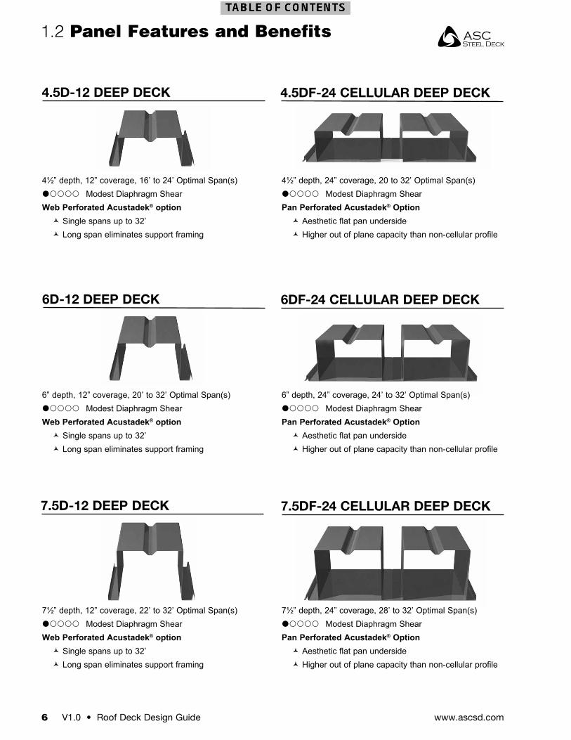
4.5D-12 DEEP DECK 4.5DF-24 CELLULAR DEEP DECK
6DF-24 CELLULAR DEEP DECK6D-12 DEEP DECK
7.5D-12 DEEP DECK 7.5DF-24 CELLULAR DEEP DECK
4½” depth, 12” coverage, 16’ to 24’ Optimal Span(s)Modest Diaphragm ShearWeb Perforated Acustadek® option Single spans up to 32’ Long span eliminates support framing
6” depth, 12” coverage, 20’ to 32’ Optimal Span(s)Modest Diaphragm ShearWeb Perforated Acustadek® option Single spans up to 32’ Long span eliminates support framing
7½” depth, 12” coverage, 22’ to 32’ Optimal Span(s)Modest Diaphragm ShearWeb Perforated Acustadek® option Single spans up to 32’ Long span eliminates support framing
4½” depth, 24” coverage, 20 to 32’ Optimal Span(s)Modest Diaphragm ShearPan Perforated Acustadek® Option Aesthetic flat pan underside Higher out of plane capacity than non-cellular profile
6” depth, 24” coverage, 24’ to 32’ Optimal Span(s)Modest Diaphragm ShearPan Perforated Acustadek® Option Aesthetic flat pan underside Higher out of plane capacity than non-cellular profile
7½” depth, 24” coverage, 28’ to 32’ Optimal Span(s)Modest Diaphragm ShearPan Perforated Acustadek® Option Aesthetic flat pan underside Higher out of plane capacity than non-cellular profile
Roof Deck Design Guide • V1.0 7www.ascsd.com
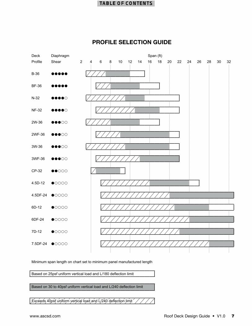
PROFILE SELECTION GUIDE
Deck Diaphragm Span (ft)Profile Shear 2 4 6 8 10 12 14 16 18 20 22 24 26 28 30 32
B-36
BF-36
N-32
NF-32
2W-36
2WF-36
3W-36
3WF-36
CP-32
4.5D-12
4.5DF-24
6D-12
6DF-24
7D-12
7.5DF-24
Minimum span length on chart set to minimum panel manufactured length
Based on 25psf uniform vertical load and L/180 deflection limit
Based on 30 to 40psf uniform vertical load and L/240 deflection limit
Exceeds 40psf uniform vertical load and L/240 deflection limit
www.ascsd.com8 V1.0 • Roof Deck Design Guide
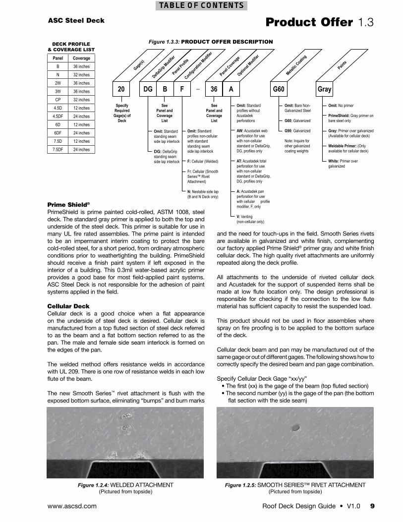
1.3 Product Offer
ASC Steel Deck offers a robust product offer. Our lightweight steel deck profiles have depths that range from 13⁄8” to 71⁄2”. Panel lengths range from 5 feet to 45 feet. Steel deck panels are supplied with both galvanized and painted finishes to meet an array of project finish requirements.
Product DescriptionTo assist designers with specifying the correct steel deck profile, see Figure 1.3.3 which details how to specify the intended product. Following these guidelines will help to eliminate requests for information and change orders due to insufficient product descriptions in the plans and specifications. Designers can be assured that the product delivered is the product intended. Simply specify the gage, panel profile, panel coverage, metallic/paint coating, and any modifiers appropriate for the desired product.
Deck Panel LengthsAll ASC Steel Deck products are manufactured to the specified length for the project. The following table summarizes the minimum and maximum lengths that can be manufactured for each profile.
Figure 1.3.1: MANUFACTURED PANEL LENGTHS
Profile Factory Cut LengthMinimum Maximum
Non-cellular B-36, N-32, 2W-36, 3W-36
3’-6” 45’-0”
CP-32 4’-0” 45’-0”4.5D-12, 6D-12, 7.5D-12
6’-0” 32’-0”
Cellular BF-36, NF-32, 2WF-36, 3WF-36
5’-0” 40’-0”
4.5DF-24, 6DF-24, 7.5DF-24
6’-0” 32’-0”
TolerancesASC Steel Deck manufactures to industry standard tolerances. The tolerances are summarized as follows.
Figure 1.3.2: PANEL TOLERANCES
Length ±1/2”Coverage Width -3/8” +3/4”Sweep 1/4” in 10’ lengthSquare 1/8” per foot width
Finish OptionsASC Steel Deck offers several finish options that are appropriate for a variety of applications. Our standard G60 galvanized finish is suitable for most applications, offering excellent corrosion protection and compatibility with fire proofing when used in UL fire rated assemblies. We also offer PrimeShield®, an economical prime paint system over bare cold rolled steel. PrimeShield offers the steel limited interim protection from rusting during transport and erection before the weather-tight roof system is applied. PrimeShield should
not be used in high humidity or corrosive environments. Prime paint over galvanized steel deck can also be specified to obtain the benefit of the corrosion protection of galvanized steel deck with a factory applied prime paint substrate.
GalvanizedASC Steel Deck offers steel deck products that are galvanized in accordance with ASTM A 653. The standard galvanized coating is G60 (0.6 ounce per square foot). G-90 (0.9 ounce per square foot) is recommended for high humidity and corrosive conditions. G-40 (0.4 ounce per square foot) may be specified for greater economy. Heavier galvanized finishes than G-90 can be specified for more severe environmental conditions and exposures. Inquire for product availability and minimum order sizes for G-40 or galvanizing heavier than G-90.
All ASC Steel Deck galvanized decks are manufactured from chemically treated steel coil in accordance with ASTM A 653. Chemical treatment is often referred to as passivation. The chemical treatment protects the galvanized steel from developing white rust during storage and transport of both coil and finished product. Some field-applied paint systems may not be compatible with the chemical treatment. The paint manufacture should be consulted to determine how the deck should be prepared prior to painting. ASC Steel Deck is not responsible for the adhesion of field applied primers and paints.
Galvanized with Prime PaintASC Steel Deck offers all of its standard galvanized options with factory applied prime paint on the underside of the deck. The prime paint is available in standard gray. White primer is also available. The standard 0.3mil water-based gray acrylic primer has been specially developed to provide superior adhesion to the galvanized steel deck and is suitable for use in many UL fire rated assemblies. Factory applied primer is an impermanent interim coating that is intended to have finish paint applied after the deck is installed. The galvanized with prime paint option may eliminate the need for any special surface preparation for field applied paint applications which is often a requirement for chemically treated bare galvanized steel deck panels. ASC Steel Deck is not responsible for the adhesion of paint systems applied in the field.
Cellular deck is offered with a galvanized steel pan or a prime paint over galvanized steel pan. This 0.3mil gray primer is applied to the underside of the pan prior to resistance welding or riveting the cellular deck beam to the pan. Our new Smooth Series™ rivet attachment is flush with the exposed bottom surface, omitting visible “bumps” and burn marks, eliminating the cost of touch-ups associated with resistance welded deck products. Resistance welded deck, the current industry standard, leaves burn marks on the pan which generally require cleaning and touch-up prior to the application of a finish paint system being applied. Touching up the burn marks is generally much more cost effective than preparing an unpainted, chemically treated surface for the application of a field primer. The prime painted galvanized pan provides a good substrate for the application of most field-applied paint systems. ASC Steel Deck is not responsible for the adhesion of paint systems applied in the field.
ASC Steel Deck
Roof Deck Design Guide • V1.0 9www.ascsd.com
Product Offer 1.3
Prime Shield®
PrimeShield is prime painted cold-rolled, ASTM 1008, steel deck. The standard gray primer is applied to both the top and underside of the steel deck. This primer is suitable for use in many UL fire rated assemblies. The prime paint is intended to be an impermanent interim coating to protect the bare cold-rolled steel, for a short period, from ordinary atmospheric conditions prior to weathertighting the building. PrimeShield should receive a finish paint system if left exposed in the interior of a building. This 0.3mil water-based acrylic primer provides a good base for most field-applied paint systems. ASC Steel Deck is not responsible for the adhesion of paint systems applied in the field.
Cellular DeckCellular deck is a good choice when a flat appearance on the underside of steel deck is desired. Cellular deck is manufactured from a top fluted section of steel deck referred to as the beam and a flat bottom section referred to as the pan. The male and female side seam interlock is formed on the edges of the pan.
The welded method offers resistance welds in accordance with UL 209. There is one row of resistance welds in each low flute of the beam.
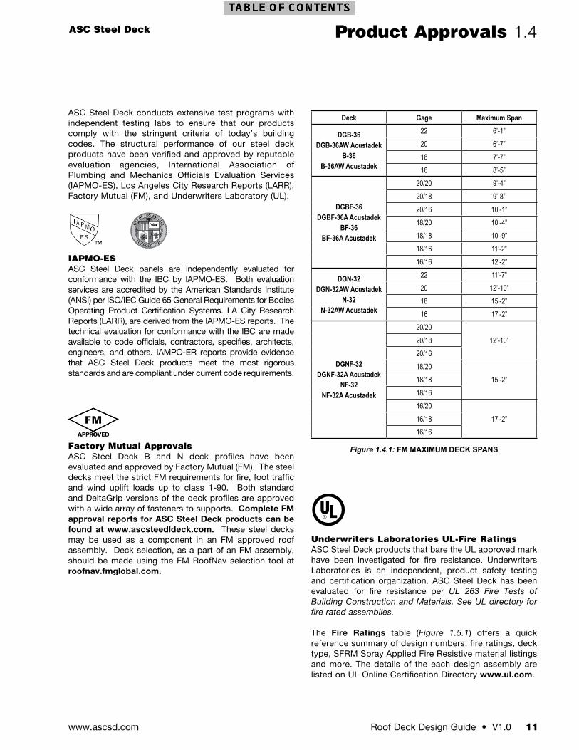
The new Smooth Series™ rivet attachment is flush with the exposed bottom surface, eliminating “bumps” and burn marks
DECK PROFILE & COVERAGE LIST
Panel Coverage
B 36 inches
N 32 inches
2W 36 inches
3W 36 inches
CP 32 inches
4.5D 12 inches
4.5DF 24 inches
6D 12 inches
6DF 24 inches
7.5D 12 inches
7.5DF 24 inches
Figure 1.3.3: PRODUCT OFFER DESCRIPTION
DG20 GrayG60B 36F A
DeltaGrip
Modifier
Gage(s)
Paints
Metallic
Coating
Panel Profile
Panel Cover
age
Configuration Modifier
Optional M
odifier
_
Omit: Standard profiles without Acustadek perforations
AW: Acustadek web perforation for use with non-cellular standard or DeltaGrip, DG, profiles only
AT: Acustadek total perforation for use with non-cellular standard or DeltaGrip, DG, profiles only
A: Acustadek pan perforation for use with cellular profile modifier, F, only
V: Venting (non-cellular only)
Omit: Bare Non-Galvanized Steel
G60: Galvanized
G90: Galvanized
Note: Inquire for other galvanized coating weights
Omit: No primer
PrimeShield: Gray primer on bare steel only
Gray: Primer over galvanized (Available for cellular deck)
Weldable Primer: (Only available for cellular deck)
White: Primer over galvanized
SeePanel and Coverage
List
SeePanel and Coverage
List
Specify Required
Gage(s) of Deck
Omit: Standard profiles non-cellular with standard standing seam side lap interlock
F: Cellular (Welded)
Fr: Cellular (Smooth Series™ Rivet Attachment)
N: Nestable side lap(B and N Deck only)
Omit: Standardstanding seam side lap interlock
DG: DeltaGripstanding seamside lap interlock
and the need for touch-ups in the field. Smooth Series rivets are available in galvanized and white finish, complementing our factory applied Prime Shield® primer gray and white finish cellular deck. The high quality rivet attachments are uniformly repeated along the deck profile.
All attachments to the underside of riveted cellular deck and Acustadek for the support of suspended items shall be made at low flute location only. The design professional is responsible for checking if the connection to the low flute material has sufficient capacity to resist the suspended load.
This product should not be used in floor assemblies where spray on fire proofing is to be applied to the bottom surface of the deck.
Cellular deck beam and pan may be manufactured out of the same gage or out of different gages. The following shows how to correctly specify the desired beam and pan gage combination.
Specify Cellular Deck Gage “xx/yy”• The first (xx) is the gage of the beam (top fluted section)• The second number (yy) is the gage of the pan (the bottom
flat section with the side seam)
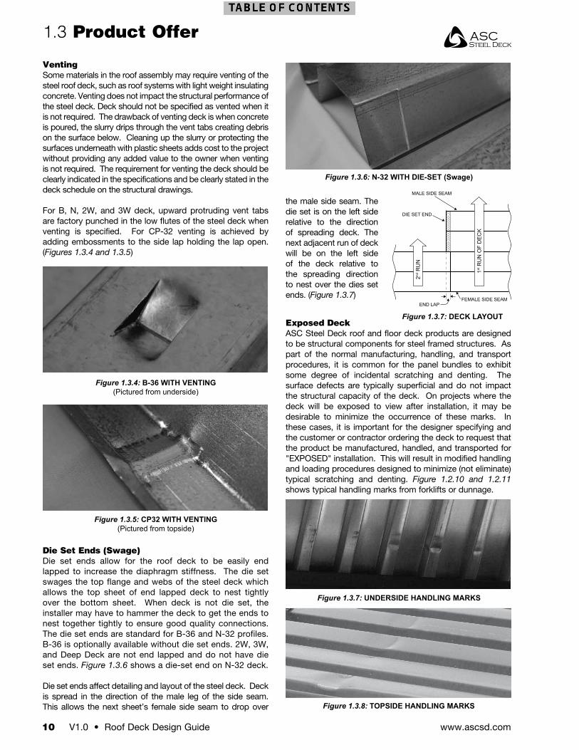
Figure 1.2.4: WELDED ATTACHMENT(Pictured from topside)
Figure 1.2.5: SMOOTH SERIES™ RIVET ATTACHMENT (Pictured from topside)
www.ascsd.com10 V1.0 • Roof Deck Design Guide
1.3 Product Offer
VentingSome materials in the roof assembly may require venting of the steel roof deck, such as roof systems with light weight insulating concrete. Venting does not impact the structural performance of the steel deck. Deck should not be specified as vented when it is not required. The drawback of venting deck is when concrete is poured, the slurry drips through the vent tabs creating debris on the surface below. Cleaning up the slurry or protecting the surfaces underneath with plastic sheets adds cost to the project without providing any added value to the owner when venting is not required. The requirement for venting the deck should be clearly indicated in the specifications and be clearly stated in the deck schedule on the structural drawings.
For B, N, 2W, and 3W deck, upward protruding vent tabs are factory punched in the low flutes of the steel deck when venting is specified. For CP-32 venting is achieved by adding embossments to the side lap holding the lap open. (Figures 1.3.4 and 1.3.5)
Die Set Ends (Swage)Die set ends allow for the roof deck to be easily end lapped to increase the diaphragm stiffness. The die set swages the top flange and webs of the steel deck which allows the top sheet of end lapped deck to nest tightly over the bottom sheet. When deck is not die set, the installer may have to hammer the deck to get the ends to nest together tightly to ensure good quality connections. The die set ends are standard for B-36 and N-32 profiles. B-36 is optionally available without die set ends. 2W, 3W, and Deep Deck are not end lapped and do not have die set ends. Figure 1.3.6 shows a die-set end on N-32 deck.
Die set ends affect detailing and layout of the steel deck. Deck is spread in the direction of the male leg of the side seam. This allows the next sheet’s female side seam to drop over
the male side seam. The die set is on the left side relative to the direction of spreading deck. The next adjacent run of deck will be on the left side of the deck relative to the spreading direction to nest over the dies set ends. (Figure 1.3.7)
Figure 1.3.4: B-36 WITH VENTING(Pictured from underside)
Figure 1.3.5: CP32 WITH VENTING(Pictured from topside)
Figure 1.3.6: N-32 WITH DIE-SET (Swage)
Figure 1.3.7: DECK LAYOUT
Figure 1.3.8: TOPSIDE HANDLING MARKS
Exposed DeckASC Steel Deck roof and floor deck products are designed to be structural components for steel framed structures. As part of the normal manufacturing, handling, and transport procedures, it is common for the panel bundles to exhibit some degree of incidental scratching and denting. The surface defects are typically superficial and do not impact the structural capacity of the deck. On projects where the deck will be exposed to view after installation, it may be desirable to minimize the occurrence of these marks. In these cases, it is important for the designer specifying and the customer or contractor ordering the deck to request that the product be manufactured, handled, and transported for "EXPOSED" installation. This will result in modified handling and loading procedures designed to minimize (not eliminate) typical scratching and denting. Figure 1.2.10 and 1.2.11 shows typical handling marks from forklifts or dunnage.
Figure 1.3.7: UNDERSIDE HANDLING MARKS
DIE SET END
MALE SIDE SEAM
FEMALE SIDE SEAMEND LAP
2nd R
UN
1st R
UN
OF
DE
CK
ASC Steel Deck
Roof Deck Design Guide • V1.0 11www.ascsd.com
Product Approvals 1.4
ASC Steel Deck conducts extensive test programs with independent testing labs to ensure that our products comply with the stringent criteria of today’s building codes. The structural performance of our steel deck products have been verified and approved by reputable evaluation agencies, International Association of Plumbing and Mechanics Officials Evaluation Services (IAPMO-ES), Los Angeles City Research Reports (LARR), Factory Mutual (FM), and Underwriters Laboratory (UL).
IAPMO-ESASC Steel Deck panels are independently evaluated for conformance with the IBC by IAPMO-ES. Both evaluation services are accredited by the American Standards Institute (ANSI) per ISO/IEC Guide 65 General Requirements for Bodies Operating Product Certification Systems. LA City Research Reports (LARR), are derived from the IAPMO-ES reports. The technical evaluation for conformance with the IBC are made available to code officials, contractors, specifies, architects, engineers, and others. IAMPO-ER reports provide evidence that ASC Steel Deck products meet the most rigorous standards and are compliant under current code requirements.
Factory Mutual Approvals ASC Steel Deck B and N deck profiles have been evaluated and approved by Factory Mutual (FM). The steel decks meet the strict FM requirements for fire, foot traffic and wind uplift loads up to class 1-90. Both standard and DeltaGrip versions of the deck profiles are approved with a wide array of fasteners to supports. Complete FM approval reports for ASC Steel Deck products can be found at www.ascsteedldeck.com. These steel decks may be used as a component in an FM approved roof assembly. Deck selection, as a part of an FM assembly, should be made using the FM RoofNav selection tool at roofnav.fmglobal.com.
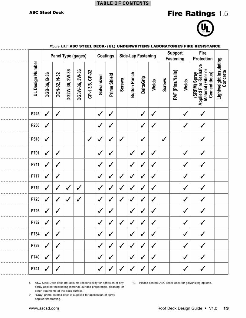
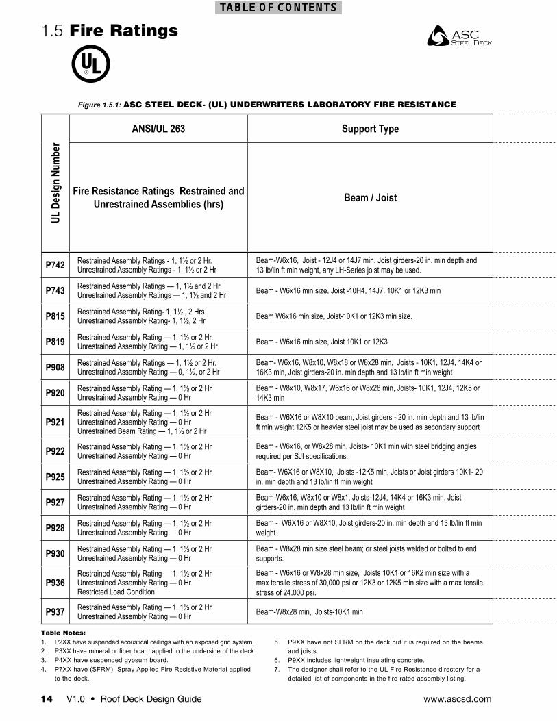
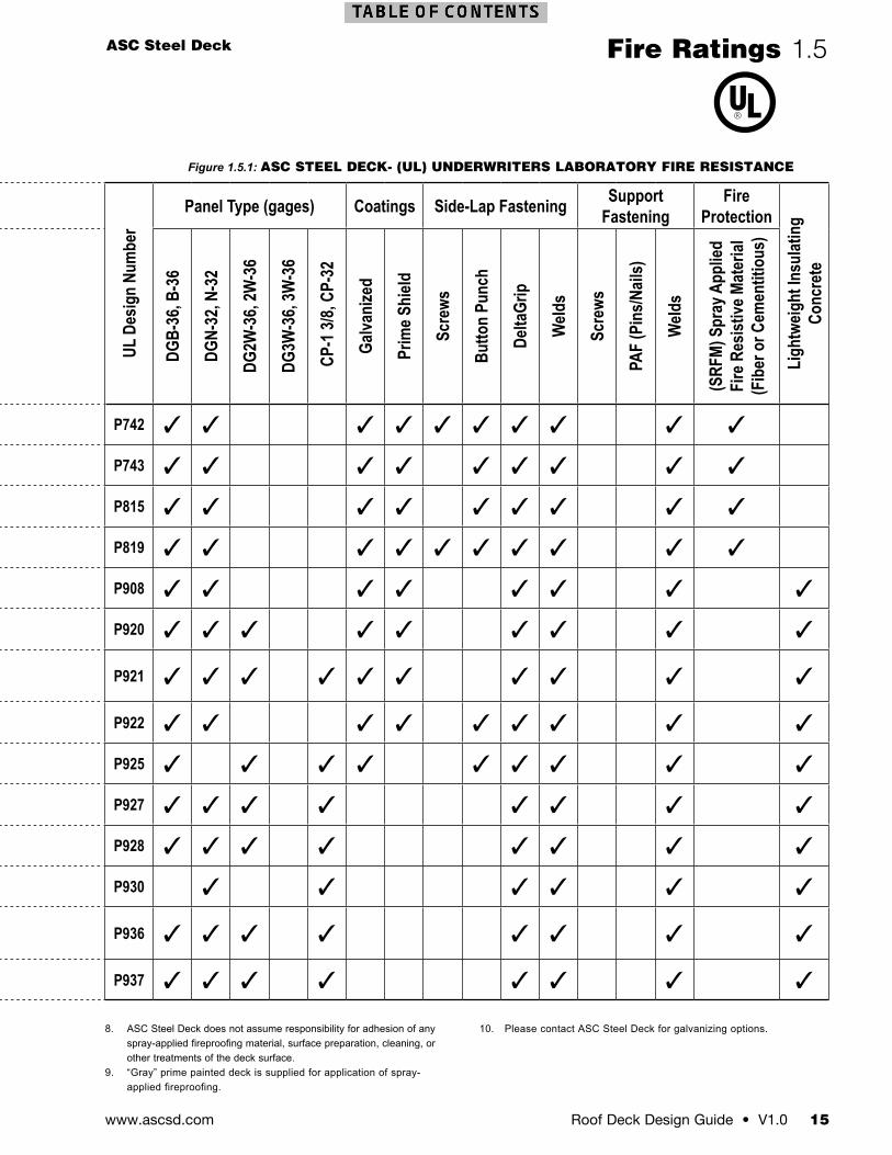
Underwriters Laboratories UL-Fire RatingsASC Steel Deck products that bare the UL approved mark have been investigated for fire resistance. Underwriters Laboratories is an independent, product safety testing and certification organization. ASC Steel Deck has been evaluated for fire resistance per UL 263 Fire Tests of Building Construction and Materials. See UL directory for fire rated assemblies.
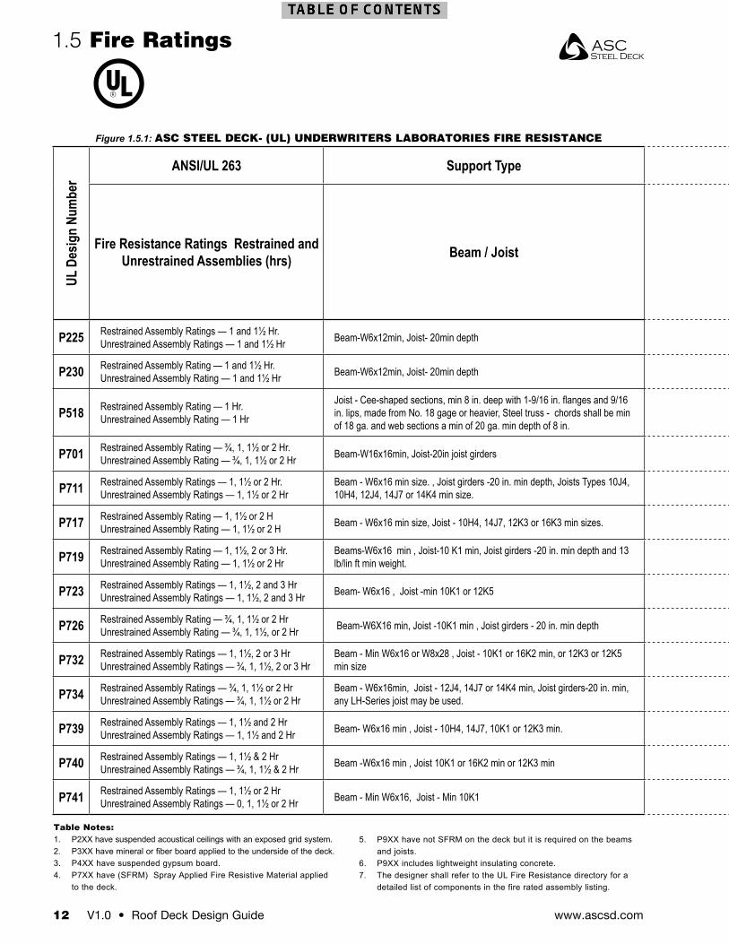
The Fire Ratings table (Figure 1.5.1) offers a quick reference summary of design numbers, fire ratings, deck type, SFRM Spray Applied Fire Resistive material listings and more. The details of the each design assembly are listed on UL Online Certification Directory www.ul.com.
Deck Gage Maximum Span
DGB-36DGB-36AW Acustadek
B-36B-36AW Acustadek
22 6’-1”20 6’-7”18 7’-7”16 8’-5”
DGBF-36DGBF-36A Acustadek
BF-36BF-36A Acustadek
20/20 9’-4”20/18 9’-8”20/16 10’-1”18/20 10’-4”18/18 10’-9”18/16 11’-2”16/16 12’-2”
DGN-32DGN-32AW Acustadek
N-32N-32AW Acustadek
22 11’-7”20 12’-10”18 15’-2”16 17’-2”
DGNF-32DGNF-32A Acustadek
NF-32NF-32A Acustadek
20/2012’-10”20/18
20/1618/20
15’-2”18/1818/1616/20
17’-2”16/1816/16
Figure 1.4.1: FM MAXIMUM DECK SPANS
www.ascsd.com12 V1.0 • Roof Deck Design Guide
1.5 Fire Ratings
Figure 1.5.1: ASC STEEL DECK- (UL) UNDERWRITERS LABORATORIES FIRE RESISTANCE Figure 1.5.1: ASC STEEL DECK- (UL) UNDERWRITERS LABORATORIES FIRE RESISTANCE
UL D
esig
n Nu
mbe
r
ANSI/UL 263 Support Type
UL D
esig
n Nu
mbe
r
Panel Type (gages) Coatings Side-Lap Fastening Support Fastening
Fire Protection
Ligh
tweig
ht In
sulat
ing
Conc
rete
Fire Resistance Ratings Restrained and Unrestrained Assemblies (hrs) Beam / Joist
DGB-
36, B
-36
DGN-
32, N
-32
DG2W
-36,
2W-3
6
DG3W
-36,
3W-3
6
CP-
1 3/8,
CP-
32
Galva
nize
d
Prim
e Shi
eld
Scre
ws
Butto
n Pu
nch
Delta
Grip
Weld
s
Scre
ws
PAF
(Pin
s/Nail
s)
Weld
s
(SRF
M) S
pray
Ap
plied
Fire
Res
istive
Ma
teria
l (Fi
ber o
r Ce
men
titio
us)
P225 Restrained Assembly Ratings — 1 and 1½ Hr. Unrestrained Assembly Ratings — 1 and 1½ Hr Beam-W6x12min, Joist- 20min depth P225
P230 Restrained Assembly Rating — 1 and 1½ Hr. Unrestrained Assembly Rating — 1 and 1½ Hr Beam-W6x12min, Joist- 20min depth P230
P518 Restrained Assembly Rating — 1 Hr. Unrestrained Assembly Rating — 1 Hr
Joist - Cee-shaped sections, min 8 in. deep with 1-9/16 in. flanges and 9/16 in. lips, made from No. 18 gage or heavier, Steel truss - chords shall be min of 18 ga. and web sections a min of 20 ga. min depth of 8 in.
P518
P701 Restrained Assembly Rating — ¾, 1, 1½ or 2 Hr. Unrestrained Assembly Rating — ¾, 1, 1½ or 2 Hr Beam-W16x16min, Joist-20in joist girders P701
P711 Restrained Assembly Ratings — 1, 1½ or 2 Hr. Unrestrained Assembly Ratings — 1, 1½ or 2 Hr
Beam - W6x16 min size. , Joist girders -20 in. min depth, Joists Types 10J4, 10H4, 12J4, 14J7 or 14K4 min size. P711
P717 Restrained Assembly Rating — 1, 1½ or 2 H Unrestrained Assembly Rating — 1, 1½ or 2 H Beam - W6x16 min size, Joist - 10H4, 14J7, 12K3 or 16K3 min sizes. P717
P719 Restrained Assembly Rating — 1, 1½, 2 or 3 Hr. Unrestrained Assembly Rating — 1, 1½ or 2 Hr
Beams-W6x16 min , Joist-10 K1 min, Joist girders -20 in. min depth and 13 lb/lin ft min weight. P719
P723 Restrained Assembly Ratings — 1, 1½, 2 and 3 Hr Unrestrained Assembly Ratings — 1, 1½, 2 and 3 Hr Beam- W6x16 , Joist -min 10K1 or 12K5 P723
P726 Restrained Assembly Rating — ¾, 1, 1½ or 2 Hr Unrestrained Assembly Rating — ¾, 1, 1½, or 2 Hr Beam-W6X16 min, Joist -10K1 min , Joist girders - 20 in. min depth P726
P732 Restrained Assembly Ratings — 1, 1½, 2 or 3 Hr Unrestrained Assembly Ratings — ¾, 1, 1½, 2 or 3 Hr
Beam - Min W6x16 or W8x28 , Joist - 10K1 or 16K2 min, or 12K3 or 12K5 min size P732
P734 Restrained Assembly Ratings — ¾, 1, 1½ or 2 Hr Unrestrained Assembly Ratings — ¾, 1, 1½ or 2 Hr
Beam - W6x16min, Joist - 12J4, 14J7 or 14K4 min, Joist girders-20 in. min, any LH-Series joist may be used. P734
P739 Restrained Assembly Ratings — 1, 1½ and 2 Hr Unrestrained Assembly Ratings — 1, 1½ and 2 Hr Beam- W6x16 min , Joist - 10H4, 14J7, 10K1 or 12K3 min. P739
P740 Restrained Assembly Ratings — 1, 1½ & 2 Hr Unrestrained Assembly Ratings — ¾, 1, 1½ & 2 Hr Beam -W6x16 min , Joist 10K1 or 16K2 min or 12K3 min P740
P741 Restrained Assembly Ratings — 1, 1½ or 2 Hr Unrestrained Assembly Ratings — 0, 1, 1½ or 2 Hr Beam - Min W6x16, Joist - Min 10K1 P741
Table Notes:1. P2XX have suspended acoustical ceilings with an exposed grid system.2. P3XX have mineral or fiber board applied to the underside of the deck.3. P4XX have suspended gypsum board.4. P7XX have (SFRM) Spray Applied Fire Resistive Material applied
to the deck.
5. P9XX have not SFRM on the deck but it is required on the beams and joists.
6. P9XX includes lightweight insulating concrete.7. The designer shall refer to the UL Fire Resistance directory for a
detailed list of components in the fire rated assembly listing.
ASC Steel Deck
Roof Deck Design Guide • V1.0 13www.ascsd.com
Fire Ratings 1.5
Figure 1.5.1: ASC STEEL DECK- (UL) UNDERWRITERS LABORATORIES FIRE RESISTANCE Figure 1.5.1: ASC STEEL DECK- (UL) UNDERWRITERS LABORATORIES FIRE RESISTANCE
UL D
esig
n Nu
mbe
r
ANSI/UL 263 Support Type
UL D
esig
n Nu
mbe
r
Panel Type (gages) Coatings Side-Lap Fastening Support Fastening
Fire Protection
Ligh
tweig
ht In
sulat
ing
Conc
rete
Fire Resistance Ratings Restrained and Unrestrained Assemblies (hrs) Beam / Joist
DGB-
36, B
-36
DGN-
32, N
-32
DG2W
-36,
2W-3
6
DG3W
-36,
3W-3
6
CP-
1 3/8,
CP-
32
Galva
nize
d
Prim
e Shi
eld
Scre
ws
Butto
n Pu
nch
Delta
Grip
Weld
s
Scre
ws
PAF
(Pin
s/Nail
s)
Weld
s
(SRF
M) S
pray
Ap
plied
Fire
Res
istive
Ma
teria
l (Fi
ber o
r Ce
men
titio
us)
P225 Restrained Assembly Ratings — 1 and 1½ Hr. Unrestrained Assembly Ratings — 1 and 1½ Hr Beam-W6x12min, Joist- 20min depth P225
P230 Restrained Assembly Rating — 1 and 1½ Hr. Unrestrained Assembly Rating — 1 and 1½ Hr Beam-W6x12min, Joist- 20min depth P230
P518 Restrained Assembly Rating — 1 Hr. Unrestrained Assembly Rating — 1 Hr
Joist - Cee-shaped sections, min 8 in. deep with 1-9/16 in. flanges and 9/16 in. lips, made from No. 18 gage or heavier, Steel truss - chords shall be min of 18 ga. and web sections a min of 20 ga. min depth of 8 in.
P518
P701 Restrained Assembly Rating — ¾, 1, 1½ or 2 Hr. Unrestrained Assembly Rating — ¾, 1, 1½ or 2 Hr Beam-W16x16min, Joist-20in joist girders P701
P711 Restrained Assembly Ratings — 1, 1½ or 2 Hr. Unrestrained Assembly Ratings — 1, 1½ or 2 Hr
Beam - W6x16 min size. , Joist girders -20 in. min depth, Joists Types 10J4, 10H4, 12J4, 14J7 or 14K4 min size. P711
P717 Restrained Assembly Rating — 1, 1½ or 2 H Unrestrained Assembly Rating — 1, 1½ or 2 H Beam - W6x16 min size, Joist - 10H4, 14J7, 12K3 or 16K3 min sizes. P717
P719 Restrained Assembly Rating — 1, 1½, 2 or 3 Hr. Unrestrained Assembly Rating — 1, 1½ or 2 Hr
Beams-W6x16 min , Joist-10 K1 min, Joist girders -20 in. min depth and 13 lb/lin ft min weight. P719
P723 Restrained Assembly Ratings — 1, 1½, 2 and 3 Hr Unrestrained Assembly Ratings — 1, 1½, 2 and 3 Hr Beam- W6x16 , Joist -min 10K1 or 12K5 P723
P726 Restrained Assembly Rating — ¾, 1, 1½ or 2 Hr Unrestrained Assembly Rating — ¾, 1, 1½, or 2 Hr Beam-W6X16 min, Joist -10K1 min , Joist girders - 20 in. min depth P726
P732 Restrained Assembly Ratings — 1, 1½, 2 or 3 Hr Unrestrained Assembly Ratings — ¾, 1, 1½, 2 or 3 Hr
Beam - Min W6x16 or W8x28 , Joist - 10K1 or 16K2 min, or 12K3 or 12K5 min size P732
P734 Restrained Assembly Ratings — ¾, 1, 1½ or 2 Hr Unrestrained Assembly Ratings — ¾, 1, 1½ or 2 Hr
Beam - W6x16min, Joist - 12J4, 14J7 or 14K4 min, Joist girders-20 in. min, any LH-Series joist may be used. P734
P739 Restrained Assembly Ratings — 1, 1½ and 2 Hr Unrestrained Assembly Ratings — 1, 1½ and 2 Hr Beam- W6x16 min , Joist - 10H4, 14J7, 10K1 or 12K3 min. P739
P740 Restrained Assembly Ratings — 1, 1½ & 2 Hr Unrestrained Assembly Ratings — ¾, 1, 1½ & 2 Hr Beam -W6x16 min , Joist 10K1 or 16K2 min or 12K3 min P740
P741 Restrained Assembly Ratings — 1, 1½ or 2 Hr Unrestrained Assembly Ratings — 0, 1, 1½ or 2 Hr Beam - Min W6x16, Joist - Min 10K1 P741
8. ASC Steel Deck does not assume responsibility for adhesion of any spray-applied fireproofing material, surface preparation, cleaning, or other treatments of the deck surface.
9. “Gray” prime painted deck is supplied for application of spray-applied fireproofing.
10. Please contact ASC Steel Deck for galvanizing options.
www.ascsd.com14 V1.0 • Roof Deck Design Guide
1.5 Fire Ratings
Figure 1.5.1: ASC STEEL DECK- (UL) UNDERWRITERS LABORATORY FIRE RESISTANCE Figure 1.5.1: ASC STEEL DECK- (UL) UNDERWRITERS LABORATORY FIRE RESISTANCE
UL D
esig
n Nu
mbe
r
ANSI/UL 263 Support Type
UL D
esig
n Nu
mbe
r
Panel Type (gages) Coatings Side-Lap Fastening Support Fastening
Fire Protection
Ligh
tweig
ht In
sulat
ing
Conc
rete
Fire Resistance Ratings Restrained and Unrestrained Assemblies (hrs) Beam / Joist
DGB-
36, B
-36
DGN-
32, N
-32
DG2W
-36,
2W-3
6
DG3W
-36,
3W-3
6
CP-
1 3/8,
CP-
32
Galva
nize
d
Prim
e Shi
eld
Scre
ws
Butto
n Pu
nch
Delta
Grip
Weld
s
Scre
ws
PAF
(Pin
s/Nail
s)
Weld
s
(SRF
M) S
pray
App
lied
Fire
Res
istive
Mat
erial
(F
iber
or C
emen
titio
us)
P742 Restrained Assembly Ratings - 1, 1½ or 2 Hr. Unrestrained Assembly Ratings - 1, 1½ or 2 Hr
Beam-W6x16, Joist - 12J4 or 14J7 min, Joist girders-20 in. min depth and 13 lb/lin ft min weight, any LH-Series joist may be used. P742
P743 Restrained Assembly Ratings — 1, 1½ and 2 HrUnrestrained Assembly Ratings — 1, 1½ and 2 Hr Beam - W6x16 min size, Joist -10H4, 14J7, 10K1 or 12K3 min P743
P815 Restrained Assembly Rating- 1, 1½ , 2 Hrs Unrestrained Assembly Rating- 1, 1½, 2 Hr Beam W6x16 min size, Joist-10K1 or 12K3 min size. P815
P819 Restrained Assembly Rating — 1, 1½ or 2 Hr. Unrestrained Assembly Rating — 1, 1½ or 2 Hr Beam - W6x16 min size, Joist 10K1 or 12K3 P819
P908 Restrained Assembly Ratings — 1, 1½ or 2 Hr. Unrestrained Assembly Rating — 0, 1½, or 2 Hr
Beam- W6x16, W8x10, W8x18 or W8x28 min, Joists - 10K1, 12J4, 14K4 or 16K3 min, Joist girders-20 in. min depth and 13 lb/lin ft min weight P908
P920 Restrained Assembly Rating — 1, 1½ or 2 Hr Unrestrained Assembly Rating — 0 Hr
Beam - W8x10, W8x17, W6x16 or W8x28 min, Joists- 10K1, 12J4, 12K5 or 14K3 min P920
P921Restrained Assembly Rating — 1, 1½ or 2 Hr Unrestrained Assembly Rating — 0 Hr Unrestrained Beam Rating — 1, 1½ or 2 Hr
Beam - W6X16 or W8X10 beam, Joist girders - 20 in. min depth and 13 lb/lin ft min weight.12K5 or heavier steel joist may be used as secondary support P921
P922 Restrained Assembly Rating — 1, 1½ or 2 Hr Unrestrained Assembly Rating — 0 Hr
Beam - W6x16, or W8x28 min, Joists- 10K1 min with steel bridging angles required per SJI specifications. P922
P925 Restrained Assembly Rating — 1, 1½ or 2 Hr Unrestrained Assembly Rating — 0 Hr
Beam- W6X16 or W8X10, Joists -12K5 min, Joists or Joist girders 10K1- 20 in. min depth and 13 lb/lin ft min weight P925
P927 Restrained Assembly Rating — 1, 1½ or 2 Hr Unrestrained Assembly Rating — 0 Hr
Beam-W6x16, W8x10 or W8x1, Joists-12J4, 14K4 or 16K3 min, Joist girders-20 in. min depth and 13 lb/lin ft min weight P927
P928 Restrained Assembly Rating — 1, 1½ or 2 Hr Unrestrained Assembly Rating — 0 Hr
Beam - W6X16 or W8X10, Joist girders-20 in. min depth and 13 lb/lin ft min weight P928
P930 Restrained Assembly Rating — 1, 1½ or 2 Hr Unrestrained Assembly Rating — 0 Hr
Beam - W8x28 min size steel beam; or steel joists welded or bolted to end supports. P930
P936Restrained Assembly Rating — 1, 1½ or 2 Hr Unrestrained Assembly Rating — 0 Hr Restricted Load Condition
Beam - W6x16 or W8x28 min size, Joists 10K1 or 16K2 min size with a max tensile stress of 30,000 psi or 12K3 or 12K5 min size with a max tensile stress of 24,000 psi.
P936
P937 Restrained Assembly Rating — 1, 1½ or 2 Hr Unrestrained Assembly Rating — 0 Hr Beam-W8x28 min, Joists-10K1 min P937
Table Notes:1. P2XX have suspended acoustical ceilings with an exposed grid system.2. P3XX have mineral or fiber board applied to the underside of the deck.3. P4XX have suspended gypsum board.4. P7XX have (SFRM) Spray Applied Fire Resistive Material applied
to the deck.
5. P9XX have not SFRM on the deck but it is required on the beams and joists.
6. P9XX includes lightweight insulating concrete.7. The designer shall refer to the UL Fire Resistance directory for a
detailed list of components in the fire rated assembly listing.
ASC Steel Deck
Roof Deck Design Guide • V1.0 15www.ascsd.com
Fire Ratings 1.5
Figure 1.5.1: ASC STEEL DECK- (UL) UNDERWRITERS LABORATORY FIRE RESISTANCE Figure 1.5.1: ASC STEEL DECK- (UL) UNDERWRITERS LABORATORY FIRE RESISTANCE
UL D
esig
n Nu
mbe
r
ANSI/UL 263 Support Type
UL D
esig
n Nu
mbe
r
Panel Type (gages) Coatings Side-Lap Fastening Support Fastening
Fire Protection
Ligh
tweig
ht In
sulat
ing
Conc
rete
Fire Resistance Ratings Restrained and Unrestrained Assemblies (hrs) Beam / Joist
DGB-
36, B
-36
DGN-
32, N
-32
DG2W
-36,
2W-3
6
DG3W
-36,
3W-3
6
CP-
1 3/8,
CP-
32
Galva
nize
d
Prim
e Shi
eld
Scre
ws
Butto
n Pu
nch
Delta
Grip
Weld
s
Scre
ws
PAF
(Pin
s/Nail
s)
Weld
s
(SRF
M) S
pray
App
lied
Fire
Res
istive
Mat
erial
(F
iber
or C
emen
titio
us)
P742 Restrained Assembly Ratings - 1, 1½ or 2 Hr. Unrestrained Assembly Ratings - 1, 1½ or 2 Hr
Beam-W6x16, Joist - 12J4 or 14J7 min, Joist girders-20 in. min depth and 13 lb/lin ft min weight, any LH-Series joist may be used. P742
P743 Restrained Assembly Ratings — 1, 1½ and 2 HrUnrestrained Assembly Ratings — 1, 1½ and 2 Hr Beam - W6x16 min size, Joist -10H4, 14J7, 10K1 or 12K3 min P743
P815 Restrained Assembly Rating- 1, 1½ , 2 Hrs Unrestrained Assembly Rating- 1, 1½, 2 Hr Beam W6x16 min size, Joist-10K1 or 12K3 min size. P815
P819 Restrained Assembly Rating — 1, 1½ or 2 Hr. Unrestrained Assembly Rating — 1, 1½ or 2 Hr Beam - W6x16 min size, Joist 10K1 or 12K3 P819
P908 Restrained Assembly Ratings — 1, 1½ or 2 Hr. Unrestrained Assembly Rating — 0, 1½, or 2 Hr
Beam- W6x16, W8x10, W8x18 or W8x28 min, Joists - 10K1, 12J4, 14K4 or 16K3 min, Joist girders-20 in. min depth and 13 lb/lin ft min weight P908
P920 Restrained Assembly Rating — 1, 1½ or 2 Hr Unrestrained Assembly Rating — 0 Hr
Beam - W8x10, W8x17, W6x16 or W8x28 min, Joists- 10K1, 12J4, 12K5 or 14K3 min P920
P921Restrained Assembly Rating — 1, 1½ or 2 Hr Unrestrained Assembly Rating — 0 Hr Unrestrained Beam Rating — 1, 1½ or 2 Hr
Beam - W6X16 or W8X10 beam, Joist girders - 20 in. min depth and 13 lb/lin ft min weight.12K5 or heavier steel joist may be used as secondary support P921
P922 Restrained Assembly Rating — 1, 1½ or 2 Hr Unrestrained Assembly Rating — 0 Hr
Beam - W6x16, or W8x28 min, Joists- 10K1 min with steel bridging angles required per SJI specifications. P922
P925 Restrained Assembly Rating — 1, 1½ or 2 Hr Unrestrained Assembly Rating — 0 Hr
Beam- W6X16 or W8X10, Joists -12K5 min, Joists or Joist girders 10K1- 20 in. min depth and 13 lb/lin ft min weight P925
P927 Restrained Assembly Rating — 1, 1½ or 2 Hr Unrestrained Assembly Rating — 0 Hr
Beam-W6x16, W8x10 or W8x1, Joists-12J4, 14K4 or 16K3 min, Joist girders-20 in. min depth and 13 lb/lin ft min weight P927
P928 Restrained Assembly Rating — 1, 1½ or 2 Hr Unrestrained Assembly Rating — 0 Hr
Beam - W6X16 or W8X10, Joist girders-20 in. min depth and 13 lb/lin ft min weight P928
P930 Restrained Assembly Rating — 1, 1½ or 2 Hr Unrestrained Assembly Rating — 0 Hr
Beam - W8x28 min size steel beam; or steel joists welded or bolted to end supports. P930
P936Restrained Assembly Rating — 1, 1½ or 2 Hr Unrestrained Assembly Rating — 0 Hr Restricted Load Condition
Beam - W6x16 or W8x28 min size, Joists 10K1 or 16K2 min size with a max tensile stress of 30,000 psi or 12K3 or 12K5 min size with a max tensile stress of 24,000 psi.
P936
P937 Restrained Assembly Rating — 1, 1½ or 2 Hr Unrestrained Assembly Rating — 0 Hr Beam-W8x28 min, Joists-10K1 min P937
8. ASC Steel Deck does not assume responsibility for adhesion of any spray-applied fireproofing material, surface preparation, cleaning, or other treatments of the deck surface.
9. “Gray” prime painted deck is supplied for application of spray-applied fireproofing.
10. Please contact ASC Steel Deck for galvanizing options.
www.ascsd.com16 V1.0 • Roof Deck Design Guide
like buckling increases. The moment capacity of the deck increases with the increased grade because the increasing yield strength of the steel outpaces the loss of effective compression width of the combined elements. Steel decks cannot be compared based strictly on effective section properties without considering the grade of the steel. The following demonstrates this for B-36 steel deck.
20 Gage B-36 Steel Deck Panel
Yield ksi Ie+
(in4)Ie-
(in4) Sg+
(in3) Se-
(in3) Mn+
(k-in)33 0.193 0.237 0.235 0.251 13.9537 0.187 0.233 0.233 0.247 15.5238 0.187 0.233 0.233 0.246 15.9140 0.187 0.233 0.232 0.244 16.6955 0.177 0.227 0.223 0.233 22.0280 0.173 0.223 0.218 0.233 23.51
Figure 1.6.1: EFFECTIVE SECTION PROPERTIES
Many steel deck panels are not symmetric. In most cases, the top and bottom flange widths are not equivalent. The bending stress and location of the neutral axis is therefore different for positive and negative bending, resulting in different positive and negative section properties.
Gross Section PropertiesThe gross section properties of the steel deck are based on the entire cross section of the panel. Determination of gross section properties assumes that there are no compression buckling compression flanges or web elements of the steel deck and that there are no ineffective elements. The gross section properties are used in combination with effective section properties to determine the deflection of the steel deck under uniform out-of-plane loads, and for checking axial compression and bending.
Service Load Section PropertiesThe service load moment of inertia is used to determine the deflection of the steel deck for out-of-plane loads. The calculated moments of inertia are determined at a working stress level of 0.6Fy. Following accepted practice, the hybrid moment of inertia is based on the sum of two times the effective moment of inertia and the gross moment of inertia divided by three, as follows.
32 ge
d
III
+=
This deflection equation for uniformly distributed loads takes into account that, throughout the length of the span, portions of the steel deck will have low bending stress below the onset of localized compression buckling in which the gross section properties would be valid and the other portions of the span will have bending stresses high enough to push beyond the onset of localized compression buckling in which effective section properties would be appropriate.
1.6 Section Properties
Section PropertiesAll of ASC Steel Deck's section properties are calculated in accordance with the American Iron and Steel Institute Specification for the Design of Cold-Formed Steel Structural Members, AISI S100-2007, Section B. Section properties can be used to develop the bending capacity of the steel deck for out-of-plane loads, which are typically defined by gravity or wind uplift. The section properties can also be used to determine the combined axial and bending capacity of the steel deck for bracing walls or other vertical elements of a building.
The section properties for steel roof deck, like other cold-formed steel members such as Cee, Zee, hat-shaped purlins, studs, and track are based on post-buckling strength. Post-buckling strength is based on the concept that compression flanges and portions of webs will exhibit some local buckling prior to the load capacity of the member being reached. To account for this, the widths of the flat compression elements of the steel deck are reduced for the purpose of determining the section properties, excluding the portion that can no longer effectively carry compression loads. This reduction of the gross section properties results in the effective section properties.
Steel ThicknessThe thickness of steel roof deck is typically specified by a gage designation. The design of steel deck is dependent on the specified design base steel thickness in accordance with AISI S100-2007. The base steel thickness should not be confused with the total coated thickness, which is the combined thickness of the base steel, the optional galvanizing thickness, and any factory-applied paint system thickness.
The minimum acceptable base steel thickness to be supplied shall not be less than 95% of the design base steel thickness. This is specified in Section A2.4 Delivered Minimum Thickness of AISI S100-2007.
Some standards reference non-mandatory tables that list the thickness of sheet steel by gage designation. These include the AISC Manual of Steel Construction in the Miscellaneous Information section of the appendix and AWS D1.3 in the Annex. Both references indicate that the values are non-mandatory and are for reference only. The nominal total coated thicknesses listed for each gage in these sources should not be used to determine if the cold-formed steel structural member, including steel deck, meets the minimum thickness requirement for the specified gage.
Effective Section PropertiesEffective section properties for a steel deck panel are used to check for the maximum bending and axial load capacities.
The effective properties are determined at the full yield stress of the steel. As the grade of steel increases, the effective section properties decrease. The effective width of the compression elements decreases as the localized plate-
ASC Steel Deck
Roof Deck Design Guide • V1.0 17www.ascsd.com
Section Properties 1.6
0.02990.03590.04780.0598
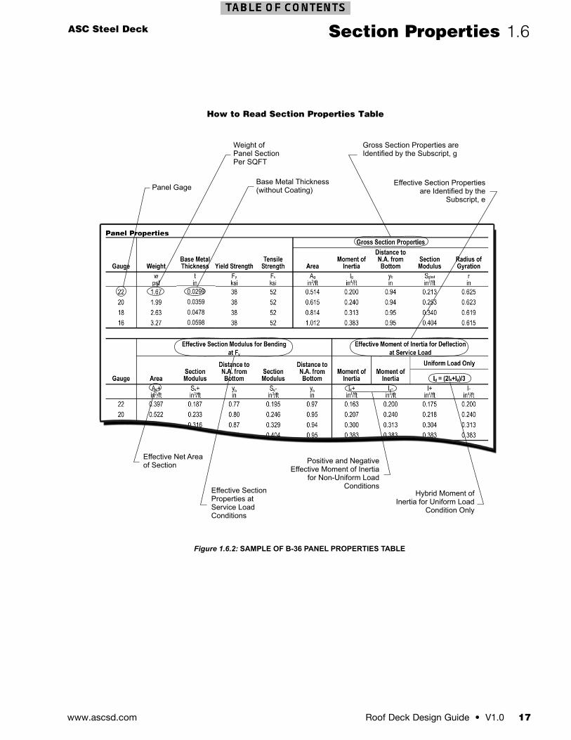
How to Read Section Properties Table
Panel Gage
Weight ofPanel SectionPer SQFT
Base Metal Thickness (without Coating)
Gross Section Properties are Identified by the Subscript, g
Effective Section Properties are Identified by the
Subscript, e
Hybrid Moment of Inertia for Uniform Load
Condition Only
Positive and Negative Effective Moment of Inertia
for Non-Uniform Load ConditionsEffective Section
Properties at Service Load Conditions
Effective Net Area of Section
Figure 1.6.2: SAMPLE OF B-36 PANEL PROPERTIES TABLE
www.ascsd.com18 V1.0 • Roof Deck Design Guide
1.7 Out of Plane Vertical Loads
Out-of-Plane LoadsOut-of-plane loads are loads applied to the panel that are perpendicular to the panel surface. These loads, uniform and non-uniform, are a combination of the applied forces due to wind, roofing materials, equipment, machinery, live loads, and other factors. The allowable and factored load tables provide the panel capacity, the deck profile, gage (base metal thickness), span length, and the number of spans created by the support spacing.
Uniformly Distributed LoadsInward out-of-plane uniform loads are typically a combination of gravity (dead, live, and snow) and inward wind loading conditions.
INWARD DISTRIBUTION LOAD, w (lbs/ft2)
OUTWARD DISTRIBUTION LOAD, w (lbs/ft2)
Figure 1.7.1: INWARD DISTRIBUTED LOAD
Outward out-of-plane uniform loads are typically wind uplift loads.
INWARD DISTRIBUTION LOAD, w (lbs/ft2)
OUTWARD DISTRIBUTION LOAD, w (lbs/ft2)
Figure 1.7.2: OUTWARD DISTRIBUTED LOAD
The allowable load capacities for each panel type, subject to uniform inward and/or outward load conditions, are determined by equations of mechanics and the published section properties. The panel capacities for outward uniform load conditions (wind uplift) shall be determined by the designer. ASC Steel Deck publishes inward allowable,(fb/Ω), and factored, (ϕfb), uniform distributed load tables that are based upon the bending capacity of the steel deck panels. In addition, service level distributed loads subject to varied deflection limits are presented in the tables. Where no deflection limit is listed, the panel bending capacity governs for the span and deflection limit combination.
Openings, Holes or PenetrationsThe reinforcement of openings, holes, or penetrations in the diaphragm shall be in accordance with the Steel Deck Institute (SDI) Manual of Construction with Steel Deck. Alternatively, for openings that exceed the scope of the SDI Manual of Construction with Steel Deck, the designer should provide framing to transfer vertical and lateral loads around the opening in the steel deck.
Cantilever End ConditionsFor cantilever end conditions, where the end of the deck panel is unsupported, the allowable length of the cantilever shall be determined by the designer using the published section properties, deflection limits, and material strength of the specified panel.
UNIFORM LOAD (psf )
CANTILEVEREDEND LENGTH
L
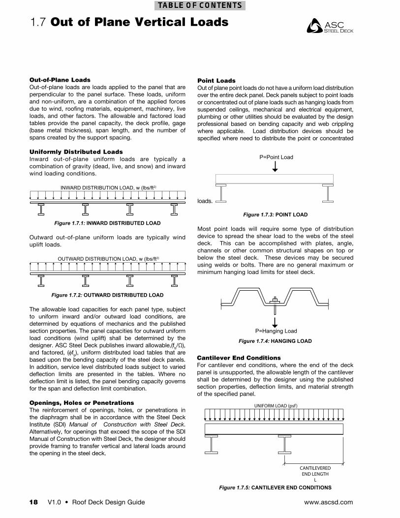
P=Point Load
Point LoadsOut of plane point loads do not have a uniform load distribution over the entire deck panel. Deck panels subject to point loads or concentrated out of plane loads such as hanging loads from suspended ceilings, mechanical and electrical equipment, plumbing or other utilities should be evaluated by the design professional based on bending capacity and web crippling where applicable. Load distribution devices should be specified where need to distribute the point or concentrated
loads.
Figure 1.7.3: POINT LOAD
Most point loads will require some type of distribution device to spread the shear load to the webs of the steel deck. This can be accomplished with plates, angle, channels or other common structural shapes on top or below the steel deck. These devices may be secured using welds or bolts. There are no general maximum or minimum hanging load limits for steel deck.
Figure 1.7.5: CANTILEVER END CONDITIONS
P=Hanging Load
Figure 1.7.4: HANGING LOAD
ASC Steel Deck
Roof Deck Design Guide • V1.0 19www.ascsd.com
Out of Plane Vertical Loads 1.7
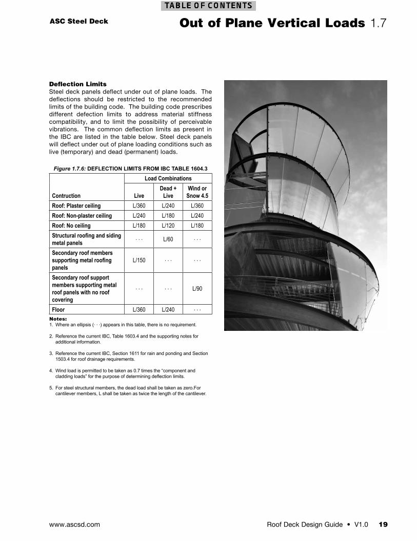
Figure 1.7.6: DEFLECTION LIMITS FROM IBC TABLE 1604.3
Contruction
Load Combinations
Live Dead +
Live Wind or
Snow 4.5Roof: Plaster ceiling L/360 L/240 L/360Roof: Non-plaster ceiling L/240 L/180 L/240Roof: No ceiling L/180 L/120 L/180Structural roofing and siding metal panels
. . . L/60 . . .
Secondary roof members supporting metal roofing panels
L/150 . . . . . .
Secondary roof support members supporting metal roof panels with no roof covering
. . . . . . L/90
Floor L/360 L/240 . . .Notes:1. Where an ellipsis (. . .) appears in this table, there is no requirement.
2. Reference the current IBC, Table 1603.4 and the supporting notes for additional information.
3. Reference the current IBC, Section 1611 for rain and ponding and Section 1503.4 for roof drainage requirements.
4. Wind load is permitted to be taken as 0.7 times the “component and cladding loads” for the purpose of determining deflection limits.
5. For steel structural members, the dead load shall be taken as zero.For cantilever members, L shall be taken as twice the length of the cantilever.
Deflection LimitsSteel deck panels deflect under out of plane loads. The deflections should be restricted to the recommended limits of the building code. The building code prescribes different defection limits to address material stiffness compatibility, and to limit the possibility of perceivable vibrations. The common deflection limits as present in the IBC are listed in the table below. Steel deck panels will deflect under out of plane loading conditions such as live (temporary) and dead (permanent) loads.
www.ascsd.com20 V1.0 • Roof Deck Design Guide
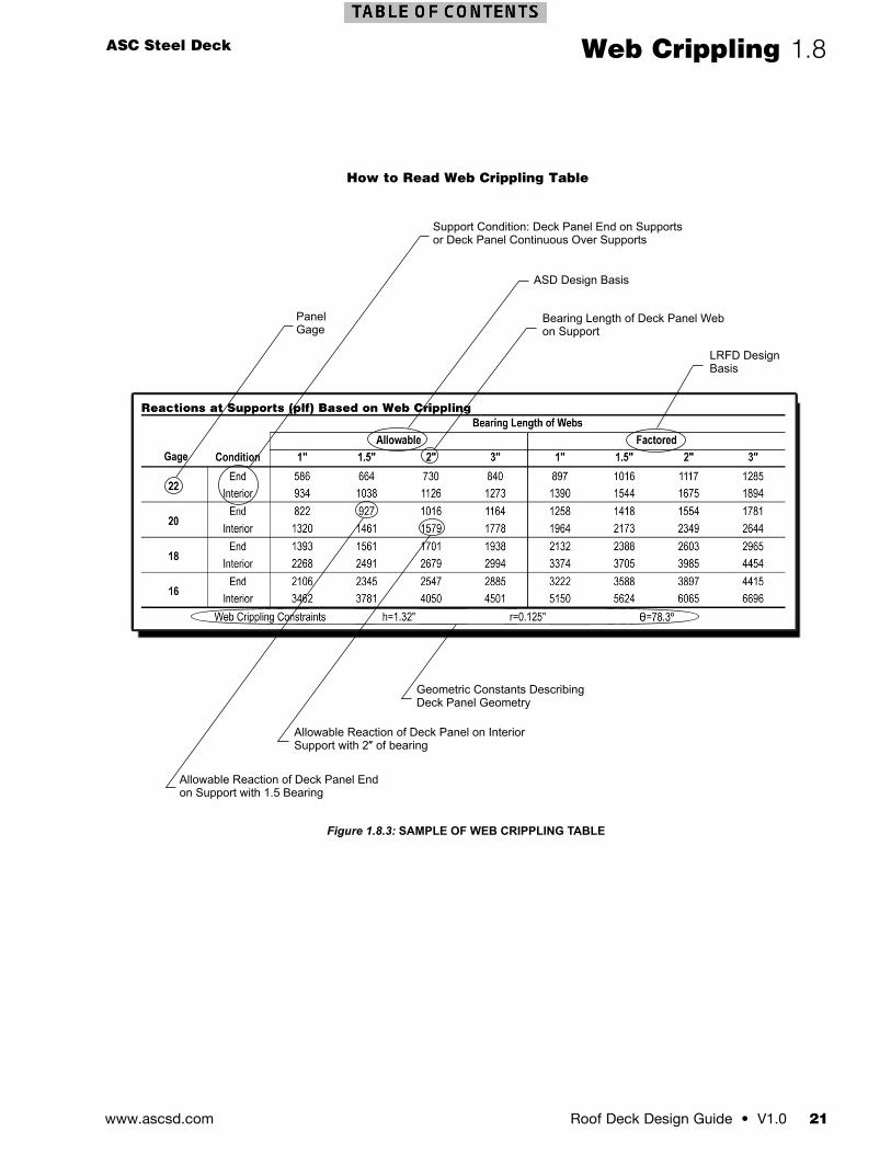
Point or Line Load ReactionsFor load conditions that exceed the uniform reaction tables, including point load and line loads on the steel deck panel, the maximum reactions should be based on the web crippling capacity for the steel deck. Reactions exceeding the published values, or for conditions other than a uniformly distributed loads, shall be determined by the designer in accordance with section C3.4 of the North American Specifications for the Design of Cold-Formed Steel Structural Members for multi-web steel panels and the geometric constants presented in the web crippling tables for the deck panel.
1.8 Web Crippling
Steel Deck Reactions at SupportsSteel deck reactions at supports are governed by the web crippling capacity of the steel deck webs on the supporting member. This is calculated in accordance with Section C3.4 of AISI S100-2007 for multi-web steel decks.
Reactions Due to Uniform LoadsThe end and interior reactions listed in the tables in the IAPMO ER-161 report are for a uniformly distributed out-of-plane load applied to the deck (see Figure 1.8.1).
Figure 1.8.1: UNIFORM DISTRIBUTED OUT-OF-PLANE LOAD
The allowable Rn/Ω and factored ϕRn reactions presented in the tables are in pounds per linear foot running axially along the support for a given deck-bearing length (the support member width) on the support. This is based on the web crippling capacity multiplied by the number of webs per foot. Figure 1.8.3 shows how to read the reaction tables in the IAPMO ER-161 report.
Panels must be attached to supports with fastener patterns not less than the minimum attachment patterns shown for the deck panel.
R, END REACTION (plf )
R, INTERIORREACTION (plf )
UNIFORM DISTRIBUTION LOAD
UNIFORM LOAD (psf) INTERIORBEARINGLENGTH
UNIFORM LOAD (psf)
UNIFORM LOAD (psf)
R R
Figure 1.8.2: SUPPORT REACTIONS
ASC Steel Deck
Roof Deck Design Guide • V1.0 21www.ascsd.com
Web Crippling 1.8
How to Read Web Crippling Table
PanelGage
Support Condition: Deck Panel End on Supports or Deck Panel Continuous Over Supports
ASD Design Basis
Bearing Length of Deck Panel Web on Support
LRFD DesignBasis
Geometric Constants DescribingDeck Panel Geometry
Allowable Reaction of Deck Panel on InteriorSupport with 2″ of bearing
Allowable Reaction of Deck Panel Endon Support with 1.5 Bearing
Gage
Figure 1.8.3: SAMPLE OF WEB CRIPPLING TABLE
www.ascsd.com22 V1.0 • Roof Deck Design Guide
1.9 In Plane Diaphragm Shear
Diaphragm Shear and FlexibilityDiaphragm shear and flexibility for steel deck diaphragms have been developed through a combination of fastener strength testing, full-scale diaphragm shear testing, and analytic equations. The steel deck panels produced by ASC Steel Deck can be used in assemblies not covered in this design guide using the design methods in the Steel Deck Institute, Diaphragm Design Manual, 3rd Edition.
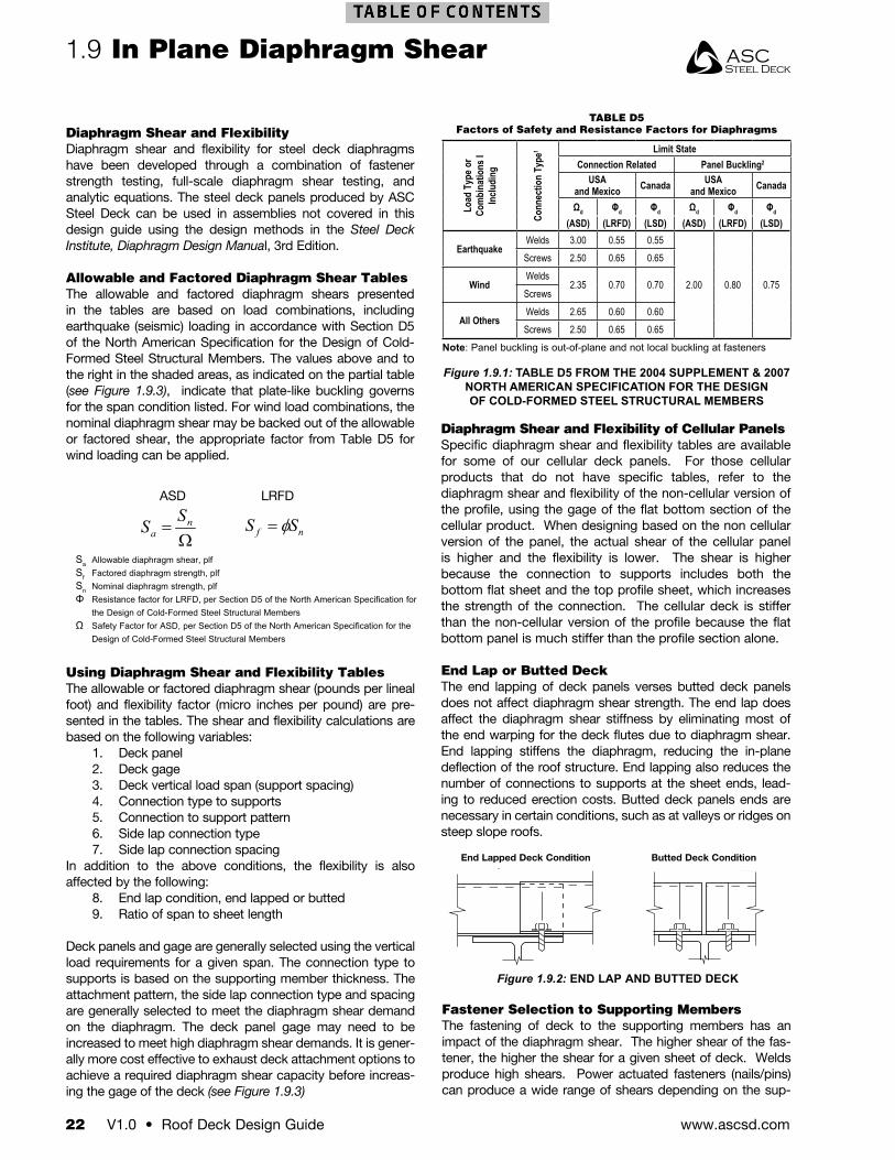
Allowable and Factored Diaphragm Shear TablesThe allowable and factored diaphragm shears presented in the tables are based on load combinations, including earthquake (seismic) loading in accordance with Section D5 of the North American Specification for the Design of Cold-Formed Steel Structural Members. The values above and to the right in the shaded areas, as indicated on the partial table (see Figure 1.9.3), indicate that plate-like buckling governs for the span condition listed. For wind load combinations, the nominal diaphragm shear may be backed out of the allowable or factored shear, the appropriate factor from Table D5 for wind loading can be applied.
Diaphragm Shear and Flexibility of Cellular PanelsSpecific diaphragm shear and flexibility tables are available for some of our cellular deck panels. For those cellular products that do not have specific tables, refer to the diaphragm shear and flexibility of the non-cellular version of the profile, using the gage of the flat bottom section of the cellular product. When designing based on the non cellular version of the panel, the actual shear of the cellular panel is higher and the flexibility is lower. The shear is higher because the connection to supports includes both the bottom flat sheet and the top profile sheet, which increases the strength of the connection. The cellular deck is stiffer than the non-cellular version of the profile because the flat bottom panel is much stiffer than the profile section alone.
End Lap or Butted DeckThe end lapping of deck panels verses butted deck panels does not affect diaphragm shear strength. The end lap does affect the diaphragm shear stiffness by eliminating most of the end warping for the deck flutes due to diaphragm shear. End lapping stiffens the diaphragm, reducing the in-plane deflection of the roof structure. End lapping also reduces the number of connections to supports at the sheet ends, lead-ing to reduced erection costs. Butted deck panels ends are necessary in certain conditions, such as at valleys or ridges on steep slope roofs.
ASD LRFD
Sa Allowable diaphragm shear, plfSf Factored diaphragm strength, plfSn Nominal diaphragm strength, plfΦ Resistance factor for LRFD, per Section D5 of the North American Specification for
the Design of Cold-Formed Steel Structural MembersΩ Safety Factor for ASD, per Section D5 of the North American Specification for the
Design of Cold-Formed Steel Structural Members
Ω= n
aSS
TABLE D5Factors of Safety and Resistance Factors for Diaphragms
Load
Typ
e or
Com
bina
tions
I In
cludi
ng
Conn
ectio
n Ty
pe1 Limit State
Connection Related Panel Buckling2
USA and Mexico Canada USA
and Mexico Canada
Ωd Φd Φd Ωd Φd Φd
(ASD) (LRFD) (LSD) (ASD) (LRFD) (LSD)
EarthquakeWelds 3.00 0.55 0.55
2.00 0.80 0.75
Screws 2.50 0.65 0.65
WindWelds
2.35 0.70 0.70Screws
All OthersWelds 2.65 0.60 0.60Screws 2.50 0.65 0.65
Note: Panel buckling is out-of-plane and not local buckling at fasteners
Figure 1.9.1: TABLE D5 FROM THE 2004 SUPPLEMENT & 2007 NORTH AMERICAN SPECIFICATION FOR THE DESIGN OF COLD-FORMED STEEL STRUCTURAL MEMBERS
Using Diaphragm Shear and Flexibility TablesThe allowable or factored diaphragm shear (pounds per lineal foot) and flexibility factor (micro inches per pound) are pre-sented in the tables. The shear and flexibility calculations are based on the following variables:
1. Deck panel2. Deck gage3. Deck vertical load span (support spacing)4. Connection type to supports5. Connection to support pattern6. Side lap connection type7. Side lap connection spacing
In addition to the above conditions, the flexibility is also affected by the following:
8. End lap condition, end lapped or butted9. Ratio of span to sheet length
Deck panels and gage are generally selected using the vertical load requirements for a given span. The connection type to supports is based on the supporting member thickness. The attachment pattern, the side lap connection type and spacing are generally selected to meet the diaphragm shear demand on the diaphragm. The deck panel gage may need to be increased to meet high diaphragm shear demands. It is gener-ally more cost effective to exhaust deck attachment options to achieve a required diaphragm shear capacity before increas-ing the gage of the deck (see Figure 1.9.3)
Fastener Selection to Supporting MembersThe fastening of deck to the supporting members has an impact of the diaphragm shear. The higher shear of the fas-tener, the higher the shear for a given sheet of deck. Welds produce high shears. Power actuated fasteners (nails/pins) can produce a wide range of shears depending on the sup-
Butted Tight or Gap>emin >emin>emin >emin
2” - 1/2”+ unlimitted
Figure 1.9.2: END LAP AND BUTTED DECK
Butted Deck ConditionEnd Lapped Deck Condition
ASC Steel Deck
Roof Deck Design Guide • V1.0 23www.ascsd.com
should be installed directly over the center line of the support member.
Diaphragm Boundary Fasteners to SupportsDiaphragm boundary connection to supports, perpendicular to the deck, should be the specified attachment pattern for the steel deck panels.
Diaphragm boundary fastener spacing, parallel with panel ribs, shall not exceed the spacing, which is determined by dividing the required diaphragm shear demand by the fastener shear strength. Connector shear strengths are presented in Figures 1.11.10 and 1.11.11.
In Plane Diaphragm Shear 1.9
port member thickness and the selected fastener. Self drilling screws produce shears on the lower end of the mechanical fastener range. The fastening system must be compatible with the support member thickness and deliver the required performance for the diaphragm. Refer to the fastener section of the design guide for more information.
Side Seam/Side Lap FastenersAll standard steel deck panels have a standing seam interlock which is suitable for button punch, top seam welds, and our revolutionary DeltaGrip® side lap fastening system (for panels designated DG). The button punch side lap fastener is the most cost effective, yet provides the lowest diaphragm shear capacity. Welded top seam fastening is the least cost effective but offers significantly higher diaphragm shear capacities than button punching. The most efficient and cost effective side lap fastener type is the DeltaGrip system. This system provides high diaphragm shear capacities similar to the top seam weld with installation costs equivalent to button punching.
Another side lap fastening option is the use of screws, with nestable side lap steel deck panels. Side lap screws provide moderate diaphragm shear capacities compared to low shear button punchs and the high shear DeltaGrip systems. The installation cost of screws is greater than button punching and much less expensive than top seam welding.
Side Seam/Side Lap Fastener SpacingThe first side lap connection from the supporting member shall not be more than one-half the specified spacing of the side lap connections, (see Figure 1.9.4). No side lap connection
Qfa Allowable fastener strength using safety factor from AISI S100-2007 Table D5Qff Factored fastener strength using resistance factor from AISI S100-2007 Table D5Sa Allowable shear diaphragm demandSf Factored shear diaphragm demand
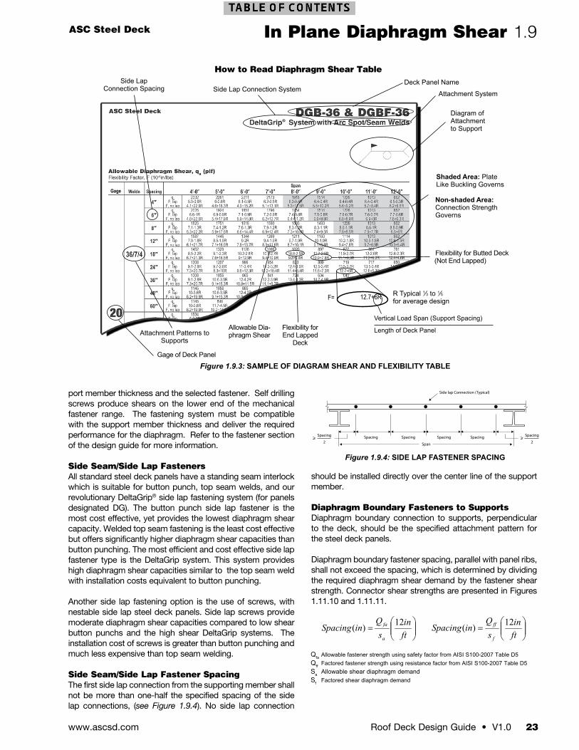
How to Read Diaphragm Shear Table
Side Lap Connection SystemDeck Panel Name
Attachment System
Diagram of Attachment to Support
Shaded Area: PlateLike Buckling Governs
Non-shaded Area: Connection Strength Governs
Side Lap Connection Spacing
Attachment Patterns to Supports
Gage of Deck Panel
Allowable Dia-phragm Shear
Flexibility for End Lapped
Deck
Flexibility for Butted Deck(Not End Lapped)
12.7+6RF= R Typical 1⁄3 to 1⁄5 for average design
Gage
Vertical Load Span (Support Spacing)
Length of Deck Panel
Figure 1.9.3: SAMPLE OF DIAGRAM SHEAR AND FLEXIBILITY TABLE
Span
Spacing Spacing Spacing Spacing
Side lap Connection (Typical)
> Spacing
2> Spacing
2
Figure 1.9.4: SIDE LAP FASTENER SPACING
®
www.ascsd.com24 V1.0 • Roof Deck Design Guide
1.10 In Plane Diaphragm Flexibility
III IIII II
∆total∆1
∆1
∆2
∆2
∆3
∆total≈ ∆1 + ∆2 + ∆3
L
b
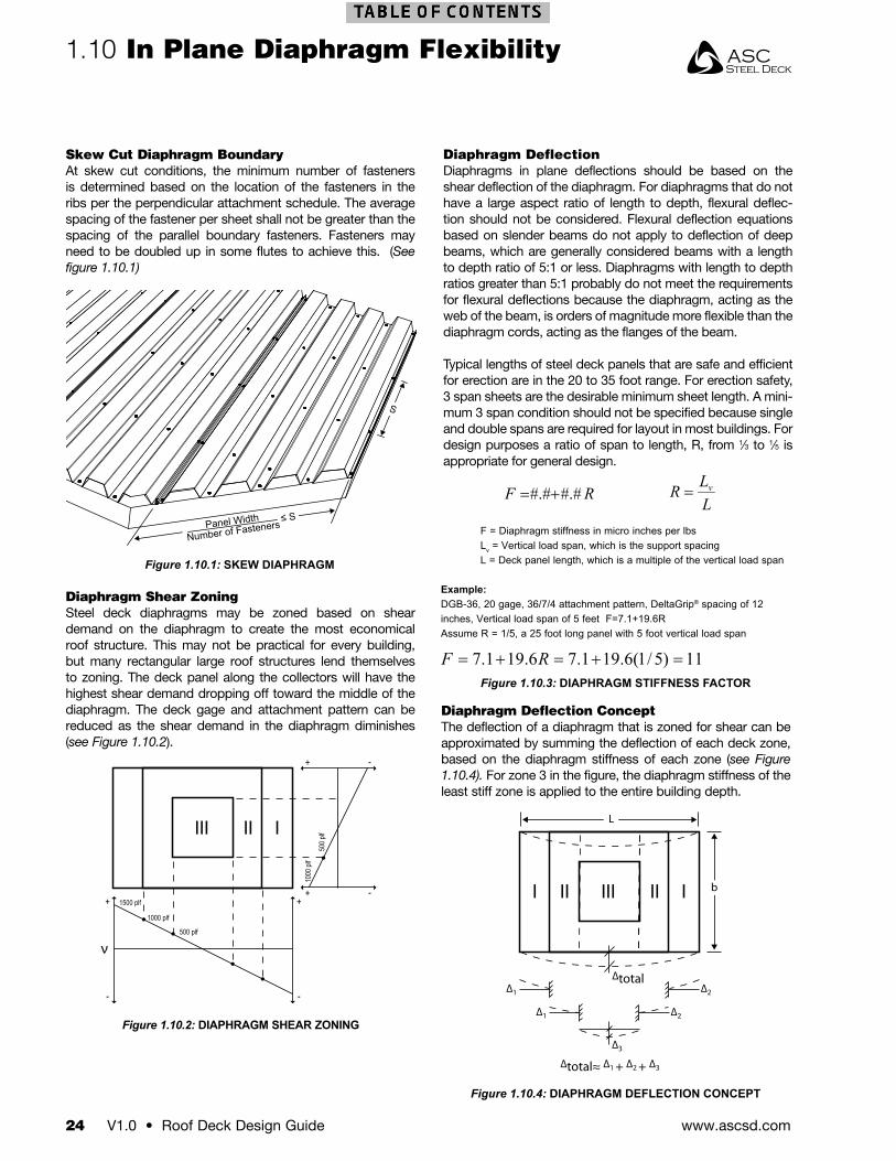
Figure 1.10.4: DIAPHRAGM DEFLECTION CONCEPT
F = Diaphragm stiffness in micro inches per lbsLv = Vertical load span, which is the support spacingL = Deck panel length, which is a multiple of the vertical load span
Example:DGB-36, 20 gage, 36/7/4 attachment pattern, DeltaGrip® spacing of 12 inches, Vertical load span of 5 feet F=7.1+19.6RAssume R = 1/5, a 25 foot long panel with 5 foot vertical load span
LLR v=RF #.##.#+=
Figure 1.10.3: DIAPHRAGM STIFFNESS FACTOR
Diaphragm Shear ZoningSteel deck diaphragms may be zoned based on shear demand on the diaphragm to create the most economical roof structure. This may not be practical for every building, but many rectangular large roof structures lend themselves to zoning. The deck panel along the collectors will have the highest shear demand dropping off toward the middle of the diaphragm. The deck gage and attachment pattern can be reduced as the shear demand in the diaphragm diminishes (see Figure 1.10.2).
Diaphragm Deflection ConceptThe deflection of a diaphragm that is zoned for shear can be approximated by summing the deflection of each deck zone, based on the diaphragm stiffness of each zone (see Figure 1.10.4). For zone 3 in the figure, the diaphragm stiffness of the least stiff zone is applied to the entire building depth.
Diaphragm DeflectionDiaphragms in plane deflections should be based on the shear deflection of the diaphragm. For diaphragms that do not have a large aspect ratio of length to depth, flexural deflec-tion should not be considered. Flexural deflection equations based on slender beams do not apply to deflection of deep beams, which are generally considered beams with a length to depth ratio of 5:1 or less. Diaphragms with length to depth ratios greater than 5:1 probably do not meet the requirements for flexural deflections because the diaphragm, acting as the web of the beam, is orders of magnitude more flexible than the diaphragm cords, acting as the flanges of the beam.
Typical lengths of steel deck panels that are safe and efficient for erection are in the 20 to 35 foot range. For erection safety, 3 span sheets are the desirable minimum sheet length. A mini-mum 3 span condition should not be specified because single and double spans are required for layout in most buildings. For design purposes a ratio of span to length, R, from 1⁄3 to 1⁄5 is appropriate for general design.
Figure 1.10.1: SKEW DIAPHRAGM
S
Panel Width
Number of Fasteners≤ S
III II I
1500 plf
1000 plf
500 plf
+
-
+
+
-
-
+ -
1000
plf
500
plf
Figure 1.10.2: DIAPHRAGM SHEAR ZONING
Skew Cut Diaphragm BoundaryAt skew cut conditions, the minimum number of fasteners is determined based on the location of the fasteners in the ribs per the perpendicular attachment schedule. The average spacing of the fastener per sheet shall not be greater than the spacing of the parallel boundary fasteners. Fasteners may need to be doubled up in some flutes to achieve this. (See figure 1.10.1)
ASC Steel Deck
Roof Deck Design Guide • V1.0 25www.ascsd.com
In Plane Diaphragm Flexibility 1.10
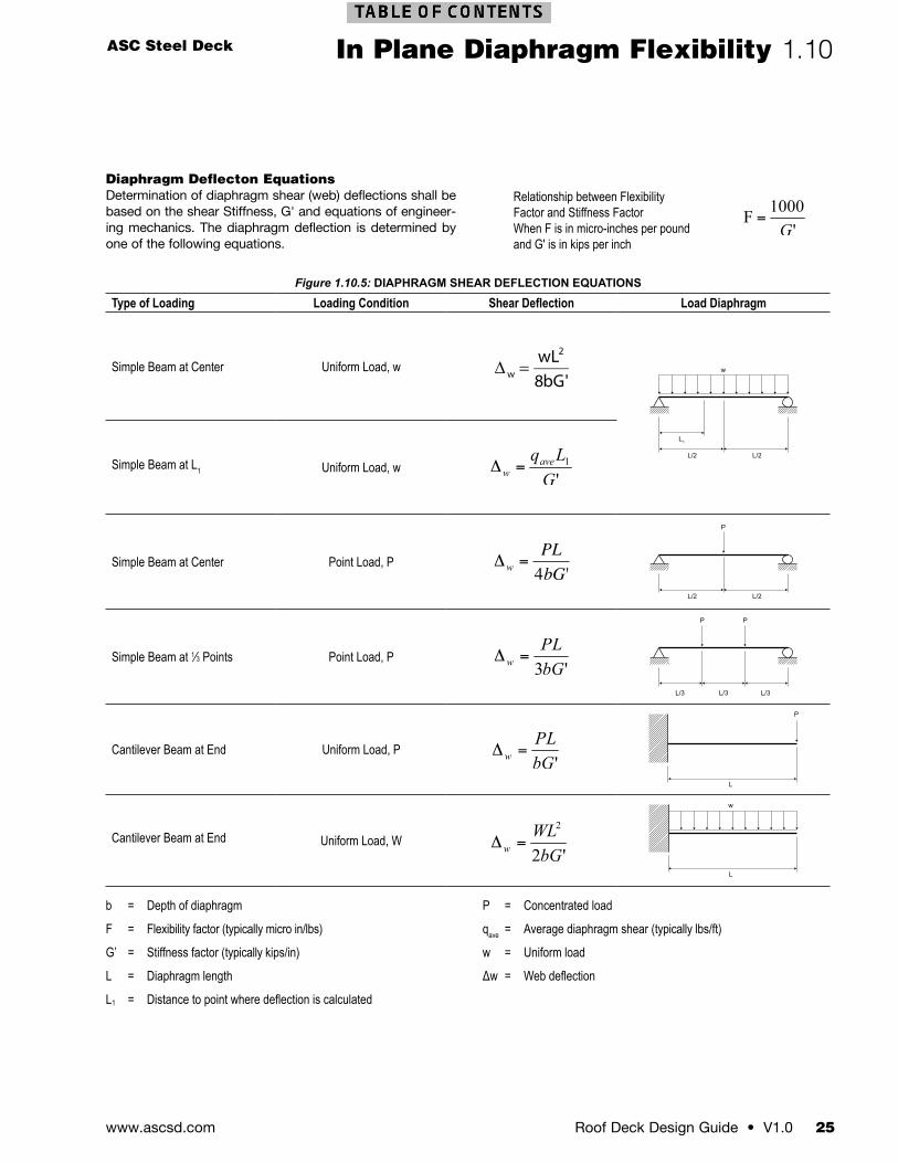
Figure 1.10.5: DIAPHRAGM SHEAR DEFLECTION EQUATIONS
Type of Loading Loading Condition Shear Deflection Load Diaphragm
Simple Beam at Center Uniform Load, w
∆w =wL2
8bG'
L/2
L1
L/2
w
Simple Beam at L1 Uniform Load, w
Simple Beam at Center Point Load, P
€
Δw
=PL
4bG'
L/2 L/2
P
Simple Beam at 1⁄3 Points Point Load, P
L/3 L/3 L/3
PP
Cantilever Beam at End Uniform Load, P
L
P
Cantilever Beam at End Uniform Load, W
L
w
Diaphragm Deflecton EquationsDetermination of diaphragm shear (web) deflections shall be based on the shear Stiffness, G' and equations of engineer-ing mechanics. The diaphragm deflection is determined by one of the following equations.
b = Depth of diaphragm
F = Flexibility factor (typically micro in/lbs)
G’ = Stiffness factor (typically kips/in)
L = Diaphragm length
L1 = Distance to point where deflection is calculated
P = Concentrated load
qave = Average diaphragm shear (typically lbs/ft)
w = Uniform load
Δw = Web deflection
Relationship between FlexibilityFactor and Stiffness FactorWhen F is in micro-inches per poundand G' is in kips per inch
www.ascsd.com26 V1.0 • Roof Deck Design Guide
1.11 Support Fastening
Support Fastening A variety of fastening systems may be used to connect steel deck to the supporting steel members. The type of fastening system used depends on the required diaphragm shear capacity, uplift capacity, and the thickness of the supporting steel members. These fastening systems include arc spot welds, arc seam welds, self-drilling screws, and power-actuated fasteners (PAF).
The strength of each fastener type is mathematically derived from specified standards and testing. The shear strength for arc spot and arc seam welds is derived from the equations in Section E2.6 of AISI S100-2007. The strength for self-drilling screws and PAF is determined in accordance with the Steel Deck Institute Diaphragm Design Manual DDM-03. The strengths for these fasteners are listed in the Weld and Shear capacities (see Figure 1.11.10 and Figure 1.11.11). The pull-out and pull-over capacity for fasteners are in accordance with Sections E4.4.1 and E4.4.2 of AISI S100-2007. The pull-out for PAF’s should be obtained from the manufacturer’s data for the selected fastener.
Fastener SelectionTo ensure quality fastening to supports, the fastener, weld, screw, or PAF must be compatible with the thickness of the steel support member. Arc spot and arc seam welds do not have a mandatory minimum support member thickness. Experience has shown that a support thickness as thin as 10 gage is reasonable. Welders with light gage welding experience can
*Below 10 gage is not recommended due to the difficulty of producing a good quality weld. **Correct drill point must be selected for the base material thickness.
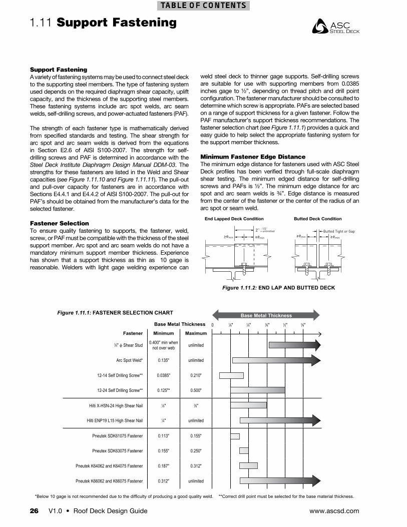
Figure 1.11.1: FASTENER SELECTION CHART
weld steel deck to thinner gage supports. Self-drilling screws are suitable for use with supporting members from 0.0385 inches gage to ½”, depending on thread pitch and drill point configuration. The fastener manufacturer should be consulted to determine which screw is appropriate. PAFs are selected based on a range of support thickness for a given fastener. Follow the PAF manufacturer’s support thickness recommendations. The fastener selection chart (see Figure 1.11.1) provides a quick and easy guide to help select the appropriate fastening system for the support member thickness.
Minimum Fastener Edge DistanceThe minimum edge distance for fasteners used with ASC Steel Deck profiles has been verified through full-scale diaphragm shear testing. The minimum edged distance for self-drilling screws and PAFs is ½”. The minimum edge distance for arc spot and arc seam welds is ¾”. Edge distance is measured from the center of the fastener or the center of the radius of an arc spot or seam weld.
Butted Tight or Gap>emin >emin>emin >emin
2” - 1/2”+ unlimitted
Butted Deck ConditionEnd Lapped Deck Condition
Figure 1.11.2: END LAP AND BUTTED DECK
Base Metal Thickness
Fastener Minimum Maximum
3⁄4" ϕ Shear Stud 0.400" min when not over web unlimited
Arc Spot Weld* 0.135" unlimited
12-14 Self Drilling Screw** 0.0385" 0.210"
12-24 Self Drilling Screw** 0.125"* 0.500"
Hilti X-HSN-24 High Shear Nail 1⁄8" 3⁄8"
Hilti ENP19 L15 High Shear Nail 1⁄4" unlimited
Pneutek SDK61075 Fastener 0.113" 0.155"
Pneutex SDK63075 Fastener 0.155" 0.250"
Pneutek K64062 and K64075 Fastener 0.187" 0.312"
Pneutek K66062 and K66075 Fastener 0.312" unlimited
Base Metal Thickness
0 1⁄8" 1⁄4" 3⁄8" 1⁄2" 5⁄8"
ASC Steel Deck
Roof Deck Design Guide • V1.0 27www.ascsd.com
Support Fastening 1.11
Pneutek Fastener
Steel Deck Panel
StructuralSteel Member
Head in Contact
Figure 1.11.5: HILTI X-HSN 24
Figure 1.11.4: HILTI X-ENP-19
Figure 1.11.3: PNEUTEK K64062
X-EDN-19 THQ12X-EDK-22 THQ12
Steel Deck Panel
Structural Steel Member
hnvs = 3/16” - 3/8”
X-EDN-19 L12
Steel Deck Panel
Structural Steel Member
hnvs = 5/16” - 3/8”
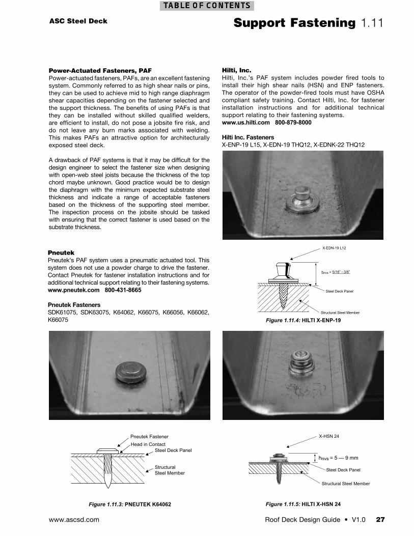
Power-Actuated Fasteners, PAFPower-actuated fasteners, PAFs, are an excellent fastening system. Commonly referred to as high shear nails or pins, they can be used to achieve mid to high range diaphragm shear capacities depending on the fastener selected and the support thickness. The benefits of using PAFs is that they can be installed without skilled qualified welders, are efficient to install, do not pose a jobsite fire risk, and do not leave any burn marks associated with welding. This makes PAFs an attractive option for architecturally exposed steel deck.
A drawback of PAF systems is that it may be difficult for the design engineer to select the fastener size when designing with open-web steel joists because the thickness of the top chord maybe unknown. Good practice would be to design the diaphragm with the minimum expected substrate steel thickness and indicate a range of acceptable fasteners based on the thickness of the supporting steel member. The inspection process on the jobsite should be tasked with ensuring that the correct fastener is used based on the substrate thickness.
Hilti, Inc.Hilti, Inc.’s PAF system includes powder fired tools to install their high shear nails (HSN) and ENP fasteners. The operator of the powder-fired tools must have OSHA compliant safety training. Contact Hilti, Inc. for fastener installation instructions and for additional technical support relating to their fastening systems. www.us.hilti.com 800-879-8000
Hilti Inc. FastenersX-ENP-19 L15, X-EDN-19 THQ12, X-EDNK-22 THQ12
Pneutek Pneutek’s PAF system uses a pneumatic actuated tool. This system does not use a powder charge to drive the fastener. Contact Pneutek for fastener installation instructions and for additional technical support relating to their fastening systems.www.pneutek.com 800-431-8665
Pneutek FastenersSDK61075, SDK63075, K64062, K66075, K66056, K66062, K66075
X-HSN 24
Steel Deck Panel
Structural Steel Member
hnvs = 5 — 9 mm
www.ascsd.com28 V1.0 • Roof Deck Design Guide
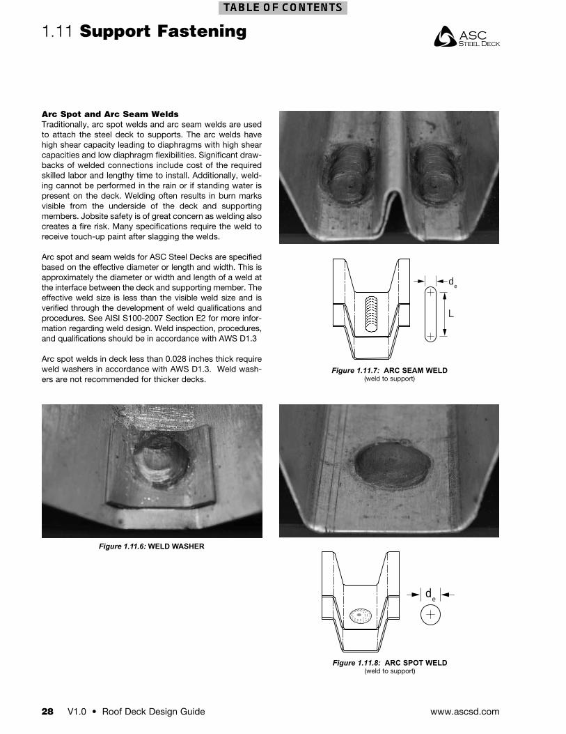
1.11 Support Fastening
de
L
de
Figure 1.11.8: ARC SPOT WELD(weld to support)
Figure 1.11.7: ARC SEAM WELD(weld to support)
Arc Spot and Arc Seam WeldsTraditionally, arc spot welds and arc seam welds are used to attach the steel deck to supports. The arc welds have high shear capacity leading to diaphragms with high shear capacities and low diaphragm flexibilities. Significant draw-backs of welded connections include cost of the required skilled labor and lengthy time to install. Additionally, weld-ing cannot be performed in the rain or if standing water is present on the deck. Welding often results in burn marks visible from the underside of the deck and supporting members. Jobsite safety is of great concern as welding also creates a fire risk. Many specifications require the weld to receive touch-up paint after slagging the welds.
Arc spot and seam welds for ASC Steel Decks are specified based on the effective diameter or length and width. This is approximately the diameter or width and length of a weld at the interface between the deck and supporting member. The effective weld size is less than the visible weld size and is verified through the development of weld qualifications and procedures. See AISI S100-2007 Section E2 for more infor-mation regarding weld design. Weld inspection, procedures, and qualifications should be in accordance with AWS D1.3
Arc spot welds in deck less than 0.028 inches thick require weld washers in accordance with AWS D1.3. Weld wash-ers are not recommended for thicker decks.
Figure 1.11.6: WELD WASHER
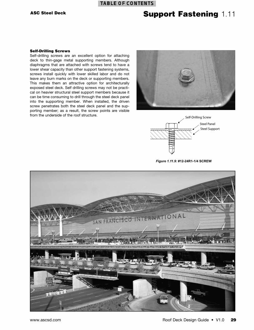
ASC Steel Deck
Roof Deck Design Guide • V1.0 29www.ascsd.com
Support Fastening 1.11
Self-Drilling Screw
Steel PanelSteel Support
Self-Drilling ScrewsSelf-drilling screws are an excellent option for attaching deck to thin-gage metal supporting members. Although diaphragms that are attached with screws tend to have a lower shear capacity than other support fastening systems, screws install quickly with lower skilled labor and do not leave any burn marks on the deck or supporting members. This makes them an attractive option for architecturally exposed steel deck. Self drilling screws may not be practi-cal on heavier structural steel support members because it can be time consuming to drill through the steel deck panel into the supporting member. When installed, the driven screw penetrates both the steel deck panel and the sup-porting member; as a result, the screw points are visible from the underside of the roof structure.
Figure 1.11.9: #12-24R1-1/4 SCREW
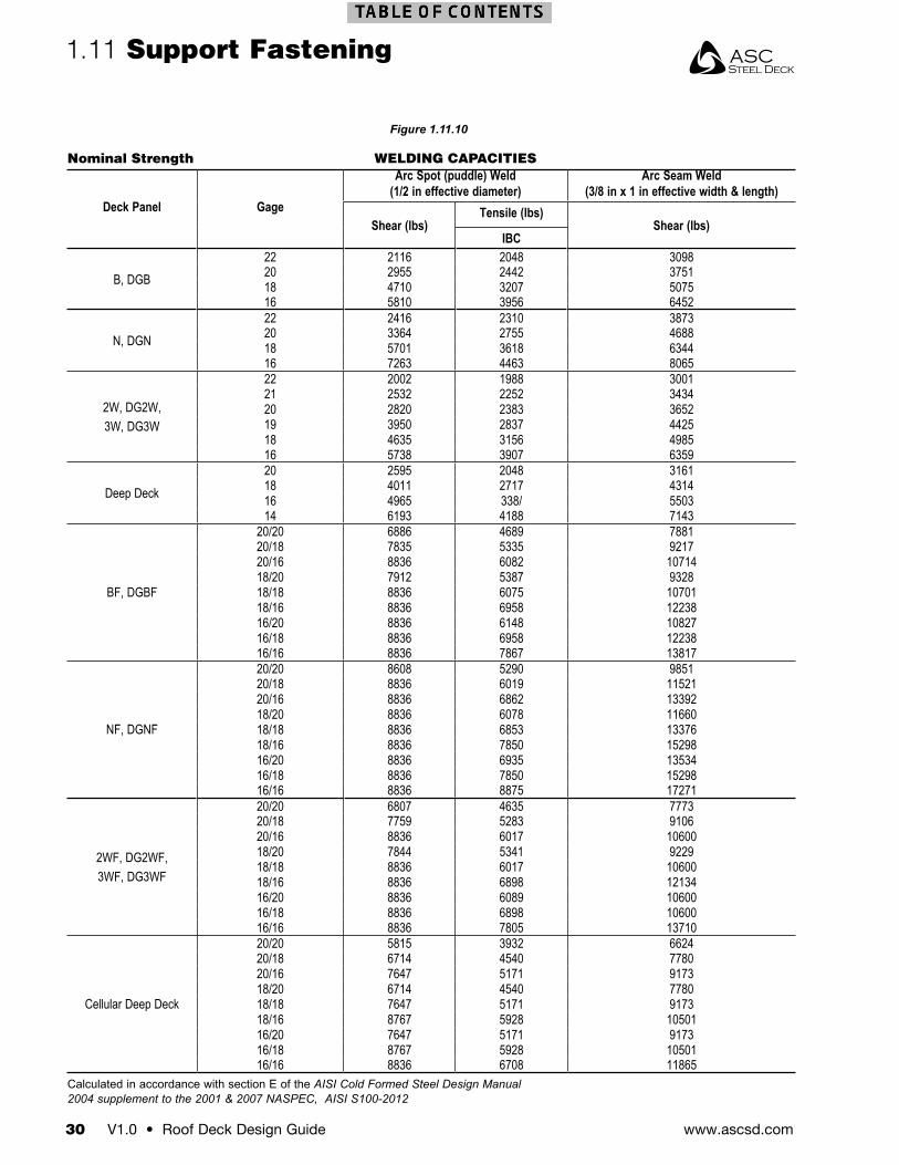
www.ascsd.com30 V1.0 • Roof Deck Design Guide
Nominal Strength WELDING CAPACITIES
Deck Panel Gage
Arc Spot (puddle) Weld(1/2 in effective diameter)
Arc Seam Weld(3/8 in x 1 in effective width & length)
Shear (lbs)Tensile (lbs)
Shear (lbs)IBC
B, DGB22 2116 2048 309820 2955 2442 375118 4710 3207 507516 5810 3956 6452
N, DGN22 2416 2310 387320 3364 2755 468818 5701 3618 634416 7263 4463 8065
2W, DG2W, 3W, DG3W
22 2002 1988 300121 2532 2252 343420 2820 2383 365219 3950 2837 442518 4635 3156 498516 5738 3907 6359
Deep Deck20 2595 2048 316118 4011 2717 431416 4965 338/ 550314 6193 4188 7143
BF, DGBF
20/20 6886 4689 788120/18 7835 5335 921720/16 8836 6082 1071418/20 7912 5387 932818/18 8836 6075 1070118/16 8836 6958 1223816/20 8836 6148 1082716/18 8836 6958 1223816/16 8836 7867 13817
NF, DGNF
20/20 8608 5290 985120/18 8836 6019 1152120/16 8836 6862 1339218/20 8836 6078 1166018/18 8836 6853 1337618/16 8836 7850 1529816/20 8836 6935 1353416/18 8836 7850 1529816/16 8836 8875 17271
2WF, DG2WF,3WF, DG3WF
20/20 6807 4635 777320/18 7759 5283 910620/16 8836 6017 1060018/20 7844 5341 922918/18 8836 6017 1060018/16 8836 6898 1213416/20 8836 6089 1060016/18 8836 6898 1060016/16 8836 7805 13710
Cellular Deep Deck
20/20 5815 3932 662420/18 6714 4540 778020/16 7647 5171 917318/20 6714 4540 778018/18 7647 5171 917318/16 8767 5928 1050116/20 7647 5171 917316/18 8767 5928 1050116/16 8836 6708 11865
Calculated in accordance with section E of the AISI Cold Formed Steel Design Manual2004 supplement to the 2001 & 2007 NASPEC, AISI S100-2012
1.11 Support Fastening
Figure 1.11.10
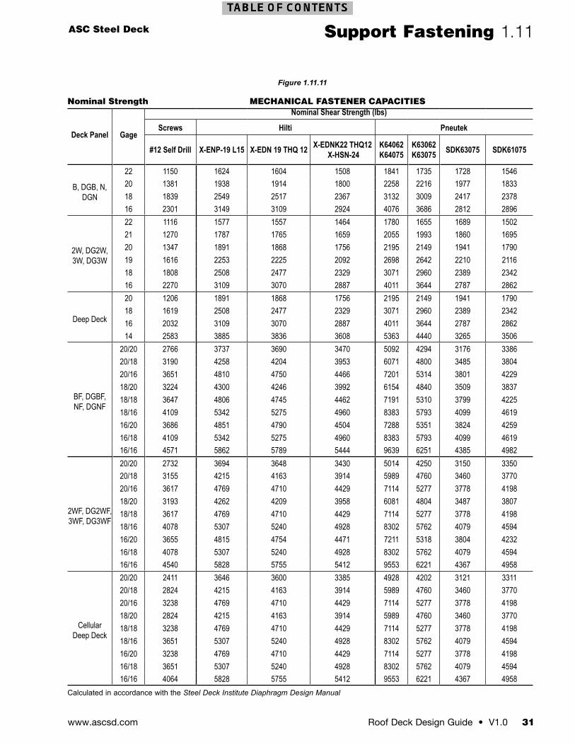
ASC Steel Deck
Roof Deck Design Guide • V1.0 31www.ascsd.com
Support Fastening 1.11
Nominal Strength MECHANICAL FASTENER CAPACITIES
Deck Panel Gage
Nominal Shear Strength (lbs)
Screws Hilti Pneutek
#12 Self Drill X-ENP-19 L15 X-EDN 19 THQ 12 X-EDNK22 THQ12 X-HSN-24
K64062K64075
K63062 K63075 SDK63075 SDK61075
B, DGB, N, DGN
22 1150 1624 1604 1508 1841 1735 1728 154620 1381 1938 1914 1800 2258 2216 1977 183318 1839 2549 2517 2367 3132 3009 2417 237816 2301 3149 3109 2924 4076 3686 2812 2896
2W, DG2W, 3W, DG3W
22 1116 1577 1557 1464 1780 1655 1689 150221 1270 1787 1765 1659 2055 1993 1860 169520 1347 1891 1868 1756 2195 2149 1941 179019 1616 2253 2225 2092 2698 2642 2210 211618 1808 2508 2477 2329 3071 2960 2389 234216 2270 3109 3070 2887 4011 3644 2787 2862
Deep Deck
20 1206 1891 1868 1756 2195 2149 1941 179018 1619 2508 2477 2329 3071 2960 2389 234216 2032 3109 3070 2887 4011 3644 2787 286214 2583 3885 3836 3608 5363 4440 3265 3506
BF, DGBF, NF, DGNF
20/20 2766 3737 3690 3470 5092 4294 3176 338620/18 3190 4258 4204 3953 6071 4800 3485 380420/16 3651 4810 4750 4466 7201 5314 3801 422918/20 3224 4300 4246 3992 6154 4840 3509 383718/18 3647 4806 4745 4462 7191 5310 3799 422518/16 4109 5342 5275 4960 8383 5793 4099 461916/20 3686 4851 4790 4504 7288 5351 3824 425916/18 4109 5342 5275 4960 8383 5793 4099 461916/16 4571 5862 5789 5444 9639 6251 4385 4982
2WF, DG2WF, 3WF, DG3WF
20/20 2732 3694 3648 3430 5014 4250 3150 335020/18 3155 4215 4163 3914 5989 4760 3460 377020/16 3617 4769 4710 4429 7114 5277 3778 419818/20 3193 4262 4209 3958 6081 4804 3487 380718/18 3617 4769 4710 4429 7114 5277 3778 419818/16 4078 5307 5240 4928 8302 5762 4079 459416/20 3655 4815 4754 4471 7211 5318 3804 423216/18 4078 5307 5240 4928 8302 5762 4079 459416/16 4540 5828 5755 5412 9553 6221 4367 4958
Cellular Deep Deck
20/20 2411 3646 3600 3385 4928 4202 3121 331120/18 2824 4215 4163 3914 5989 4760 3460 377020/16 3238 4769 4710 4429 7114 5277 3778 419818/20 2824 4215 4163 3914 5989 4760 3460 377018/18 3238 4769 4710 4429 7114 5277 3778 419818/16 3651 5307 5240 4928 8302 5762 4079 459416/20 3238 4769 4710 4429 7114 5277 3778 419816/18 3651 5307 5240 4928 8302 5762 4079 459416/16 4064 5828 5755 5412 9553 6221 4367 4958
Calculated in accordance with the Steel Deck Institute Diaphragm Design Manual
Figure 1.11.11
www.ascsd.com32 V1.0 • Roof Deck Design Guide
1.12 Side Seam Fastening
Figure 1.12.3: SIDE SEAM SELF-DRILLING SCREW
Figure 1.12.4: TOP SEAM WELDFigure 1.12.2: BUTTON PUNCH SIDE LAPS
Self-Drilling ScrewsSelf-drilling screws are used to attach nestable side lap steel decks. The screws have a mid range shear strength compared to button punches and top seam welds making them suitable for mid range diaphragm shears. The screws can be easily installed with low-skill labor using screw guns that are readily available. The screws do not leave burn marks associated with welding, but the screw points do protrude through the underside of the steel deck. As a result, screws may not be acceptable for some architecturally exposed steel decks.
Top Seam WeldThe top seam weld connects the standing seam deck side seams by welding the three layers of steel deck together. This is done after the hem is crimped using a hand or pneumatically operated crimping tool. Top seam welds can be used to produce high diaphragm shears and low flexibilities. Top seam welding is a slow process requiring skilled welders, leading to increased installation costs. The welding creates burn marks on the underside of the deck and occasional burn-through holes. Top seam welds are not recommended for architecturally exposed steel deck. Weld inspection, procedures, and qualifications should be in accordance with AWS D1.3. Due to the high cost associated with installation and inspection, top seam weld connections have been largely replaced by the DeltaGrip side lap connection.
Button PunchThe button punch attachment is used to connect standing seam side seams. This low cost attachment uses a pneumatic or hand-operated button punch tool that clinches the seam together. The button punch option is used for low shear diaphragms that generally have high flexibilities. For architecturally exposed deck, the button punch system is a good option because no unsightly burn marks occur, which are typically associated with welded connections. Although skilled labor is not required, the quality of the button punch that has been installed with a hand-operated tool is dependent on the operator. A “good” button punch should not become disengaged when a person jumps on the adjacent sheet of deck.
Side Seam AttachmentSide seam attachment is an integral part of developing the shear resistance and flexibility of a diaphragm system. The side seam attachment also creates a positive connection, limiting differential movement between the sheets of deck under out-of-plane loads. Limiting differential movement between the sheets helps to prevent damage to the roof system installed on the top side of the steel deck. The common side seam attachment systems are the button punch, top seam weld, and DeltaGrip® system for standing seam interlock side seams. Self-drilling screws are used for nestable side seams. The two common types of side seams are the standing seam interlock and the nestable side seam (see Figure 1.12.1).
Figure 1.12.1: STANDING SEAM AND NESTABLE DIAGRAM
STANDING SEAM NESTABLE
ASC Steel Deck
Roof Deck Design Guide • V1.0 33www.ascsd.com
Side Seam Fastening 1.12
Schedule Minimum Offset
Gage Dim A (in)
22 0.19
21 0.19
20 0.19
19 0.16
18 0.16
16 0.16
For SI 1 inch = 25.4mm
Plan View of DeltaGrip Punch
Dim A
A A
Side ViewDeltaGrip Punch
Dim A A
A
Dim A
Section of DeltaGrip Punch
Section A-AOpposite Direction
GO/NO-GOGAUGE
GO/NO-GOGAUGE
GO/NO-GOGAUGE
Minimum Punch“Go” Punch Acceptable
Maximum Punch“Go” Acceptable
Under Punch“No-Go”Unacceptable
Point in con-tact with gage
Gage in contact with side lap
Point protruding past gage
Gap between point & gage
Gage in contact with side lap
Gage in contact with side lap
Figure 1.12.5: DELTAGRIP PUNCH
DeltaGrip®
The DeltaGrip system was developed in 2003 to reduce the installed costs of high shear diaphragms by eliminating the costly top seam weld. This revolutionary clinching system punches three triangular tabs though the standing seam interlock side seam. This interlock creates the equivalent strength of a time consuming top seam weld with the rapid action of a pneumatically powered DeltaGrip tool. High-quality DeltaGrip connections can be installed with low-skill labor compared to the skilled welders required to make top seam welds.
DeltaGrip InspectionThe DeltaGrip system can be visually inspected from the top side of the steel deck by observing that all three layers of the side lap are engaged and that the punch-out distance meets the minimum offset required (Figure 1.12.6 and 1.12.7). To assist with this task, ASC Steel Deck has developed a Go/No-Go gage to provide a rapid jobsite check of the punch-out distances (Figure 1.12.8).
Figure 1.12.6: DELTAGRIP PUNCH OUT DISTANCES Figure 1.12.8: DELTAGRIP GO/NO-GO GUAGE
Figure 1.12.7: DELTAGRIP PUNCH VIEWS
US Patent No.’s: 7,021,108; 6,990,781
www.ascsd.com34 V1.0 • Roof Deck Design Guide
1.13 Accessories
2W Neoprene Top
2W Metal Bottom
3W Neoprene Top
3W Metal Bottom
4.5D Neoprene 6D Neoprene 7.5D Neoprene
ASC Steel Deck offers a variety of accessories to complement our steel deck offer. These include flashings, sump pans, weld washers, and profile cut top (small void) and bottom (large void) neoprene foam and galvanized steel closures.
When accessories are called for in the specifications, the location must be clearly shown on the structural and architectural drawings. Specifications that call for the use of profile cut closures where walls meet the metal deck may lead to unnecessary construction costs if they are only needed at exterior walls or specific interior locations.
B36 Large Neoprene
B36 Small Neoprene
B36 Large Metal
B36 Small Metal
B36 DECK NEOPRENE AND METAL CLOSURES
N32 Large Neoprene
N32 Small Neoprene
N32 Large Metal
N32 Small Metal
N32 DECK NEOPRENE AND METAL CLOSURES
2W NEOPRENE AND METAL CLOSURES
3W NEOPRENE AND METAL CLOSURES
DEEP DECK NEOPRENE CLOSURES
Profile Cut Neoprene Closures. Neoprene closures may be used on the top and bottom of the steel deck to reduce vapor, moisture, and air from infiltrating into the building or roof assembly. These are die-cut from black closed cell neoprene foam. The foam is manufactured in accordance with ASTM D-1056 and passes the FM VSS No. 302, UL 94HBF, and UL 94 HF1 flammability tests.
Profile Cut Metal Closures.Metal closures may be used to control animal nesting within the building structure. Metal closures may be used in combination with neoprene closures. Metal closures with calking can also be used to reduce noise infiltration as part of an acoustically engineered system. The metal closures are stamped out of 22 gage galvanized sheet steel.
Figure 1.13.5
Figure 1.13.4
Figure 1.13.3
Figure 1.13.2
Figure 1.13.1
ASC Steel Deck
Roof Deck Design Guide • V1.0 35www.ascsd.com
Accessories1.13
Sump Pans.Sump pans are a common part of many low slope roof systems. These may be provided as part of the metal deck scope of work or may be provided by the roof or mechanical trade(s) installing the drainage system.
FLASHING THICKNESS BY GAGE
Gage Base Steel Thickness22 0.029020 0.035018 0.047016 0.059014 0.070012 0.105010 0.1350
Weld Washers. 14 gauge x 3/8” dia. hole for welded attachment of CP-32. For use with 26 and 24 gage CP32 only.
Flashings.Galvanized steel flashings are custom manufactured by ASC Steel Deck to meet the project requirements. The flashings are formed from ASTM A653 SS Grade 33 galvanized steel sheets. Flashings are available in most common structural shapes in 7 gages. (Figure 1.13.9 and 1.13.10). The standard length is 10 feet, shorter lengths available upon request. The minimum width of any stiffener or flat cross section width is ¾”. Channels, Hats, and Cee’s web must be ¾” wider than the flange width, see figures below.
ZEE
STRIP
F
≥F+3⁄4"HAT
F
≥F+3⁄4"CHANNEL
Anchor Washers16 gauge x 7/16” dia. hole for welded attachment of CP-32 where higher diaphragm shear values must be achieved.
Raised Edge Weld Washer
3/4” 1”
RD39 Raised Edge Weld Washers
Anchor Waher
VariousSizes
RD40 Anchor Washer
3/4” 1”
MINIMUM FLAT WIDTH MINIMUM STIFFENER WIDTH
≥3⁄4" ≥3⁄4"
ANGLE ANGLE WITH STIFFENER
≥3⁄4"
FILLER PLATE
1"
11⁄4" Deep
28" 24"
Figure 1.13.10Figure 1.13.9
Figure 1.13.8
Figure 1.13.7
Figure 1.13.6
www.ascsd.com36 V1.0 • Roof Deck Design Guide
2.1 Acustadek®
Acustadek®
Acustadek provides the extraordinary beauty of exposed steel, while providing the same noise reduction performance of common Mineral Fiber, Fiberglass, and Bio Acoustic ceiling tile systems. It is an excellent option for reducing noise inside buildings, increasing the comfort for the occupants. Acustadek is a dual-purpose panel which helps lower costs by providing an interior finish while contributing to the structural performance of the building. This is accomplished by perforating the structural steel deck and adding fiberglass batt acoustic media in the webs or in the cells of cellular deck, turning the profile into Acustadek. Our new Smooth Series™ rivets offer a clean attachment solution for the Acustadek cellular deck system.
Web-Perforated AcustadekWeb-perforated Acustadek has 0.127” diameter holes spaced 0.375” on center in the webs of the flutes of the deck. Fiberglass batts supplied by ASC Steel Deck are field installed typically by the roofing contractor in the low flutes of the deck before the roof system is applied. Web-perforated roof decks are a component of many common roof systems. Ridged insulation boards, engineered wood panels (Plywood and OSB), fiber reinforced gypsum board, and glass matt covered gypsum board are all suitable cover boards for web-perforated steel decks.
Total Perforation AcustadekTotal perforation Acustadeck has 0.127” diameter holes spaced 0.375” on center over the entire width of the profile, except the lower interlock flutes. Fiberglass batts supplied by ASC Steel Deck are field installed by the roofing contractor in the low flutes of the deck before the roof system is applied. Total-perforated roof decks are a component of many common roof systems. Ridged insulation boards, engineered wood panels (Plywood and OSB), fiber reinforced gypsum board and glass matt covered gypsum board are all suitable cover boards for total-perforated steel decks.
Cellular AcustadekCellular Acustadek has 0.157” diameter holes spaced 0.433” inches on center in the sections of the pan below the top flutes of the steel deck. Fiberglass batts are factory inserted in the cells of the deck before shipping to the project locations. Any roof system utilizing structural or insulating concrete fill, rigid insulation board, or other roof substrate material suitable for installation on a steel roof deck may be applied to the cellular Acustadek.
Fiberglass BattsFiberglass batts are used to absorb sound in the Acustadek assemblies. ASC Steel deck supplies the fiberglass batts that a cut to size for the specified profile. The standard batts are unfaced. Optional batts encapsulated with 0.75 mil clear pvc plastic can be specified.
Acoustical PerformanceAll Acustadeks have been tested for the sound absorption characteristics of the assemblies. This is commonly presented as a Noise Reduction Coefficient (NRC). The NRC is the average of the 250, 500, 1000, and 2000 hertz sound absorption coefficients. Acustadeks have between a 0.6 and 1.0 NRC, which can meet LEED v4 EQ Credit Acoustic Performance Option 2.
Acustadek should be a portion of a holistic approach to reducing the noise level in a building. Simply specifying an NRC rating for a single material may not get the level of sound control you require. In general, steel decks tend to have better sound absorption coefficients in the higher audible range. Other materials such as fabric wall treatments and carpet tend to have better sound absorption coefficients in the lower audible frequency ranges. The use of Acustadek in combination with other materials may create the best overall quiet environment. An experienced acoustic designer is key to developing the best overall performance using ASC Steel Deck Acustadek products.
The sound absorption coefficient varies across the spectrum of audible sound. In buildings with equipment that creates a specific frequency, the sound absorption coefficient for that frequency range should determine the type of deck rather than the overall NRC rating. For example, if a machine emits a sound in the 2000 Hz range, a total perforation deck such as DGB-36AT with an absorption coefficient of 0.95 would be a better choice than a web-perforated Acustadek such
ASC Steel Deck
Roof Deck Design Guide • V1.0 37www.ascsd.com
Acustadek® 2.1
as DGB-36AW, which only has a 0.53 coefficient for the 2000 Hz range. Some sound absorption coefficients may be greater than 1.0 because of the measurement methods. When designing for a specific frequency, use 1.0 for any absorption coefficients greater than 1.0.
The type of cover board on non-cellular Acustadek has an impact on the sound absorption coefficients and NRC rating of the assembly. The acoustical testing is based on an assembly comprising the Acustadek profile, the fiberglass batts, and the cover board on top of the steel deck that supports the roof system. Historically, fiberglass board was used as the cover board on top of the steel deck. These assemblies have higher acoustical performance than modern assemblies using poly-iso insulation board on top of the deck. The Acustadek tables in this section provide information for both fiberglass and poly-iso deck cover board assemblies.
The NRC should not be confused with the Sound Transmission Coefficient (STC). STCs measure the blocking of sound through an assembly as it relates to the decibel drop in the intensity of the sound. Acustadek may not be a good choice if a high STC is required. As an example, consider a room with noisy equipment. The Acustadek may be a good solution to reduce the noise level in the room for the occupants, but may not be a good material to block the noise from escaping the room. The holes in the perforated Acustadek may in fact let more sound escape the room than a conventional deck.
Detailing and Installation of AcustadekAcustadek provides an exposed finish in the building. Steel deck is a structural element in the building and is subject to incidental dents in the handling and steel erection process. To minimize the potential damage, use 20 gage or heavier. 22 gage may be an economical option when minor dents can be tolerated; dark paint finishes or high roof structures can mask these types of minor blemishes.
Acustadek can be specified with a galvanized finish or factory prime painted over galvanized steel. Most Acustadeks will receive finish paint to meet the aesthetic requirements of the building. The galvanized steel can be field painted following the paint manufacturer’s preparation and application recommendations. As an option, factory-applied primer can be specified, which may reduce the surface preparation of the deck.
Attaching the Acustadek to the structure and connection of the side laps of the deck can impact the appearance of the installed product. Side lap top seam welds will leave burn marks in the galvanized finish and an occasional burn through should be expected. This may be unsightly if the galvanized finish is intended to be left exposed. The burns can be easily cleaned up prior to prime painting
the deck after installation. A better solution is to use the DeltaGrip® side lap connection. This mechanical interlock connection provides high strength similar to a weld without any thermal damage to the deck or galvanized coating and is not visible from the underside of the deck. Arc spot and arc seam welds may also leave visible burn marks on the deck near the support or on the underside of the supporting steel. A good alternative to welding the deck to supports is to attach the deck with self-drilling screws or power-actuated fasteners (PAF), such as the high shear nails manufactured by Hilti, Inc. or fasteners manufactured by Pneutek Inc. that are intended for decking applications.
Structural Performance of AcustadekThe perforation of the webs, top and bottom flutes and pans of the Acustadeks has a small impact on the structural performance of the deck profiles. Section properties are reduced from the non-Acustadek version of the profiles leading to reduced vertical load capacity. The reactions at supports are unaffected by the perforation in the Acustadek. The diaphragm shear and flexibility of cellular and web-perforated Acustadek is the same as the non-Acustadek version of the profile. Total perforation Acustadek flexibility is the same as the nonacoustical version of the profile, but the diaphragm shear capacity is 85% of the non-Acustadek profile. (See Figure 7.1.1)
Figure 7.1.1: ACUSTADEK STRUCTURAL PROPERTIES SUMMARY
Section Properties Use Acustadek section properties
Reactions at Supports(based on Web Crippling)
Use non Acustadek reactions for the profile
Diaphragm Shear Web perforated and cellular pan perforated use shear for non-Acustadek profileTotal perforated Acustadek use 85% of the diaphragm shear for the profile
Diaphragm Flexibility Use diaphragm flexibility of the non-perforated profile
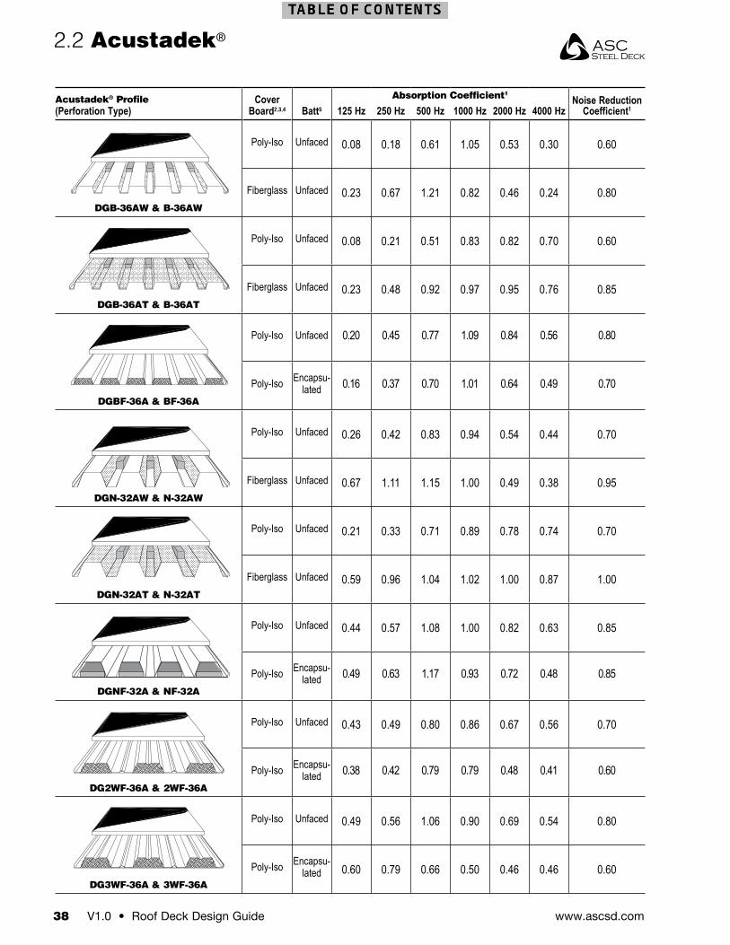
www.ascsd.com38 V1.0 • Roof Deck Design Guide
Acustadek® Profile(Perforation Type)
Cover Board2,3,4 Batt5
Absorption Coefficient1Noise Reduction
Coefficient1125 Hz 250 Hz 500 Hz 1000 Hz 2000 Hz 4000 Hz
DGB-36AW & B-36AW
Poly-Iso Unfaced 0.08 0.18 0.61 1.05 0.53 0.30 0.60
Fiberglass Unfaced 0.23 0.67 1.21 0.82 0.46 0.24 0.80
DGB-36AT & B-36AT
Poly-Iso Unfaced 0.08 0.21 0.51 0.83 0.82 0.70 0.60
Fiberglass Unfaced 0.23 0.48 0.92 0.97 0.95 0.76 0.85
DGBF-36A & BF-36A
Poly-Iso Unfaced 0.20 0.45 0.77 1.09 0.84 0.56 0.80
Poly-Iso Encapsu-lated 0.16 0.37 0.70 1.01 0.64 0.49 0.70
DGN-32AW & N-32AW
Poly-Iso Unfaced 0.26 0.42 0.83 0.94 0.54 0.44 0.70
Fiberglass Unfaced 0.67 1.11 1.15 1.00 0.49 0.38 0.95
DGN-32AT & N-32AT
Poly-Iso Unfaced 0.21 0.33 0.71 0.89 0.78 0.74 0.70
Fiberglass Unfaced 0.59 0.96 1.04 1.02 1.00 0.87 1.00
DGNF-32A & NF-32A
Poly-Iso Unfaced 0.44 0.57 1.08 1.00 0.82 0.63 0.85
Poly-Iso Encapsu-lated 0.49 0.63 1.17 0.93 0.72 0.48 0.85
DG2WF-36A & 2WF-36A
Poly-Iso Unfaced 0.43 0.49 0.80 0.86 0.67 0.56 0.70
Poly-Iso Encapsu-lated 0.38 0.42 0.79 0.79 0.48 0.41 0.60
DG3WF-36A & 3WF-36A
Poly-Iso Unfaced 0.49 0.56 1.06 0.90 0.69 0.54 0.80
Poly-Iso Encapsu-lated 0.60 0.79 0.66 0.50 0.46 0.46 0.60
2.2 Acustadek®
RD23 B-36 Acustadek (Web)
RD24 BF-36 Acustadek (Pan only)
RD27 2WF-36 & 3WF-36 Acustadek (Pan only)
RD27 2WF-36 & 3WF-36 Acustadek (Pan only)
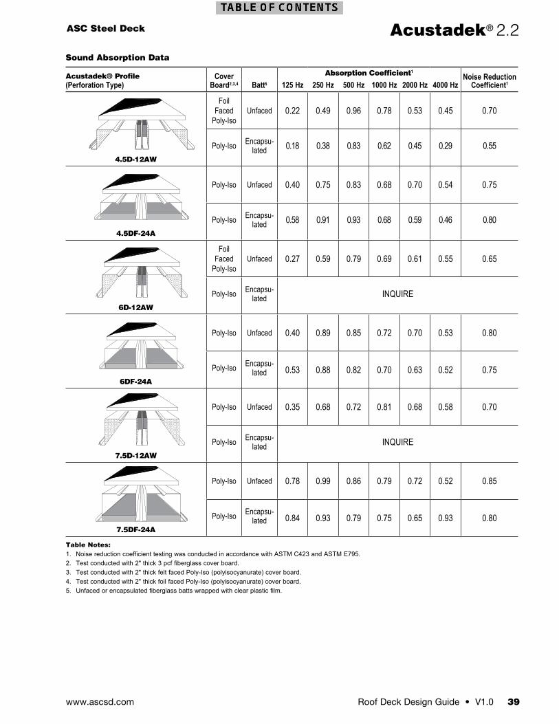
ASC Steel Deck
Roof Deck Design Guide • V1.0 39www.ascsd.com
Acustadek® 2.2Sound Absorption Data
Acustadek® Profile(Perforation Type)
Cover Board2,3,4 Batt5
Absorption Coefficient1Noise Reduction
Coefficient1125 Hz 250 Hz 500 Hz 1000 Hz 2000 Hz 4000 Hz
4.5D-12AW
Foil Faced
Poly-IsoUnfaced 0.22 0.49 0.96 0.78 0.53 0.45 0.70
Poly-Iso Encapsu-lated 0.18 0.38 0.83 0.62 0.45 0.29 0.55
4.5DF-24A
Poly-Iso Unfaced 0.40 0.75 0.83 0.68 0.70 0.54 0.75
Poly-Iso Encapsu-lated 0.58 0.91 0.93 0.68 0.59 0.46 0.80
6D-12AW
Foil Faced
Poly-IsoUnfaced 0.27 0.59 0.79 0.69 0.61 0.55 0.65
Poly-Iso Encapsu-lated INQUIRE
6DF-24A
Poly-Iso Unfaced 0.40 0.89 0.85 0.72 0.70 0.53 0.80
Poly-Iso Encapsu-lated 0.53 0.88 0.82 0.70 0.63 0.52 0.75
7.5D-12AW
Poly-Iso Unfaced 0.35 0.68 0.72 0.81 0.68 0.58 0.70
Poly-Iso Encapsu-lated INQUIRE
7.5DF-24A
Poly-Iso Unfaced 0.78 0.99 0.86 0.79 0.72 0.52 0.85
Poly-Iso Encapsu-lated 0.84 0.93 0.79 0.75 0.65 0.93 0.80
Table Notes:1. Noise reduction coefficient testing was conducted in accordance with ASTM C423 and ASTM E795.2. Test conducted with 2" thick 3 pcf fiberglass cover board.3. Test conducted with 2" thick felt faced Poly-Iso (polyisocyanurate) cover board.4. Test conducted with 2" thick foil faced Poly-Iso (polyisocyanurate) cover board.5. Unfaced or encapsulated fiberglass batts wrapped with clear plastic film.
4-1/2” Deep Deck Acustadek (Web)
6” Deep Deck Acustadek (Web)
7-1/2” Deep Deck Acustadek (Web)
4-1/2” Deep Deck Cellular Acustadek (Pan)
6” Deep Deck Cellular Acustadek (Pan)
7-1/2” Deep Deck Cellular Acustadek (Pan)
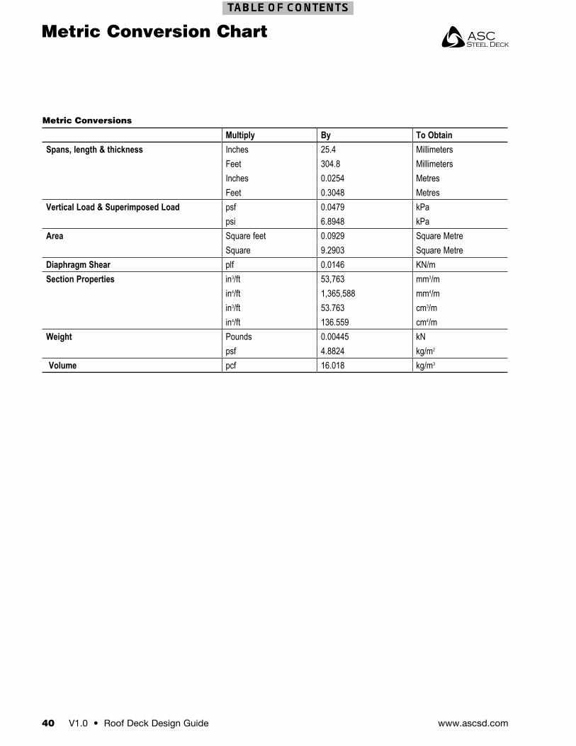
www.ascsd.com40 V1.0 • Roof Deck Design Guide
Metric Conversions
Multiply By To ObtainSpans, length & thickness Inches 25.4 Millimeters
Feet 304.8 MillimetersInches 0.0254 MetresFeet 0.3048 Metres
Vertical Load & Superimposed Load psf 0.0479 kPapsi 6.8948 kPa
Area Square feet 0.0929 Square MetreSquare 9.2903 Square Metre
Diaphragm Shear plf 0.0146 KN/mSection Properties in3/ft 53,763 mm3/m
in4/ft 1,365,588 mm4/min3/ft 53.763 cm3/min4/ft 136.559 cm4/m
Weight Pounds 0.00445 kNpsf 4.8824 kg/m2
Volume pcf 16.018 kg/m3
Metric Conversion Chart
All information stated in the catalog is correct at time of printing and subject to change without notice, check our website for the latest version. ©2007-2018 ASC Profiles LLC All trademarks are the property of their respective owners. All rights reserved. Version 0218 Pub 0218 (DL022x)
Manufacturing Facilities
ASC Steel Deck • Sacramento, CA2110 Enterprise Boulevard
West Sacramento, CA 95691916-372-6851800-726-2727
ASC Steel Deck • Fontana, CA10905 Beech AvenueFontana, CA 92337
Visit us at:www.ascsd.com