Embed Size (px)
Citation preview
General Information. . . . . . . . . . . . . . . . . . . . B2 - B4
OCAL-BLUE Steel Conduit . . . . . . . . . . . . . . . . . . B5
OCAL-BLUE Couplings. . . . . . . . . . . . . . . . . . . . . B6
OCAL-BLUE Elbows . . . . . . . . . . . . . . . . . . . . . . . B7Standard Radius Elbows andLarge Radius Elbows
OCAL-BLUE Nipples . . . . . . . . . . . . . . . . . . . . . . B8and Liquidtight Connectors
OCAL-BLUE Double-Coat . . . . . . . . . . . . . . . . . . B9Conduit Bodies
OCAL-BLUE Double-Coat GUA Series . . . . B10-B11Conduit Outlet BoxesGUA, GUAB, GUAC, GUAD, GUALGUAM, GUAN, GUAT, GUAW, GUAX
Aluminum Outlet Boxes and Covers . . . . . . B12-B13Hazardous Locations
OCAL-BLUE Double-Coat . . . . . . . . . . . . . . . . . B14Sealing FittingsEYS, EYSX, EYD, EYDX, EZS, EZD
Double-Coat FS and FD Series Boxes . . . . . . . . B15
OCAL Beam Clamps – U-Bolts . . . . . . . . . . . . . . B16
Straps – Clamp Back Spacers, Pipe Spacers. . . B17
OCAL-BLUE Double-Coat . . . . . . . . . . . . . . . . . B18Pulling Elbows and Mogul Fittings
OCAL-BLUE Double-Coat . . . . . . . . . . . . . . . . . B19Service Entrance and Malleable Elbows
OCAL-BLUE Double-Coat Hubs and . . . . . . . . . B20Split Couplings
OCAL-BLUE Double-Coat Unions . . . . . . . . . . . B21
OCAL-BLUE Double-CoatReducing Couplings. . . . . . . . . . . . . . . . . . . . . B22
Star Teck Extreme® . . . . . . . . . . . . . . . . . . . . . . . B23
Sealing Compounds – Used forHazardous Locations . . . . . . . . . . . . . . . . . . . . B23
OCAL Channel and Accessories. . . . . . . . . . . . . B24PVC Coated Steel Strut316 Stainless Steel Strut
Pipe Straps, Hanger Rod and . . . . . . . . . . . B25-B26Strut Accessories
Kopr-Shield™ Compound. . . . . . . . . . . . . . . . . . . B27
OCAL Patching Material . . . . . . . . . . . . . . . . . . . B28
OCAL Installation Tools. . . . . . . . . . . . . . . . . . . . B29Manufactured By Rigid® Tool Co. . . . . . . . B30-B31
Urethane Interior Coating Chemical . . . . . . . . . . B32Resistance Chart
PVC Coating Chemical . . . . . . . . . . . . . . . . . . . . B33Resistance Chart
NEMA Standards . . . . . . . . . . . . . . . . . . . . . . . . B34
NEC 310-16 . . . . . . . . . . . . . . . . . . . . . . . . . . . . B35
NEC Table 8 . . . . . . . . . . . . . . . . . . . . . . . . . . . . B36
OCAL-BLUE PVC Specifications . . . . . . . . . . . . B37
OCAL Recommended Installation Procedures. . . . . . . . . . . . . . . . . . . . . . . . . . . . B38
B
412031.B01 OCAL 3/5 3/13/03 5:01 PM Page 1
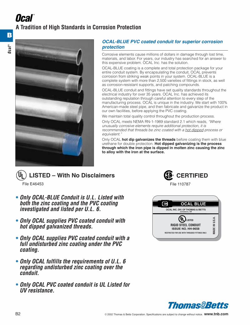
OCAL-BLUE PVC coated conduit for superior corrosionprotection
Corrosive elements cause millions of dollars in damage through lost time,materials, and labor. For years, our industry has searched for an answer tothis expensive problem. OCAL Inc. has the solution.OCAL-BLUE coating is a complete and total protection package for yourentire conduit system. By encapsulating the conduit, OCAL preventscorrosion from striking weak points in your system. OCAL-BLUE is acomplete system with more than 2,500 varieties of fittings in stock, as wellas corrosion-resistant supports, and patching compounds.OCAL-BLUE conduit and fittings have set quality standards throughout theelectrical industry for over 35 years. OCAL Inc. has achieved itsoutstanding reputation through careful attention to every step of themanufacturing process. OCAL is unique in the industry. We start with 100%American-made steel pipe, and then fabricate and galvanize the product inour own facilities, before applying the PVC coating. We maintain total quality control throughout the production process.Only OCAL meets NEMA RN-1-1989 standard 2.1 which reads, “Whereunusually corrosive elements require additional protection, it isrecommended that threads be zinc coated with a hot dipped process orequivalent.”Only OCAL hot dip galvanizes the threads before coating them with blueurethane for double protection. Hot dipped galvanizing is the processthrough which the iron pipe is dipped in molten zinc causing the zincto alloy with the iron at the surface.
A Tradition of High Standards in Corrosion Protection
• Only OCAL-BLUE Conduit is U.L. Listed withboth the zinc coating and the PVC coatinginvestigated and listed per U.L. 6.
• Only OCAL supplies PVC coated conduit withhot dipped galvanized threads.
• Only OCAL supplies PVC coated conduit with afull undisturbed zinc coating under the PVCcoating.
• Only OCAL fulfills the requirements of U.L. 6regarding undisturbed zinc coating over theconduit.
• Only OCAL PVC coated conduit is UL Listed forUV resistance.
¤ LISTED – With No DisclaimersFile E46453
® CERTIFIEDFile 110787
RESTRICTED FOR USE WITH THREADED FITTINGS ONLY.
RIGID STEEL CONDUITISSUE NO. HH-9658
LISTED
MAD
E IN
U.S
.A.
OCAL INC. DIV. OF THOMAS & BETTSJonesboro, AR
OCAL BLUE
B2 © 2002 Thomas & Betts Corporation. Specifications are subject to change without notice. www.tnb.com
Ocal
®
B
412031.B01 OCAL 3/5 3/13/03 5:01 PM Page 2
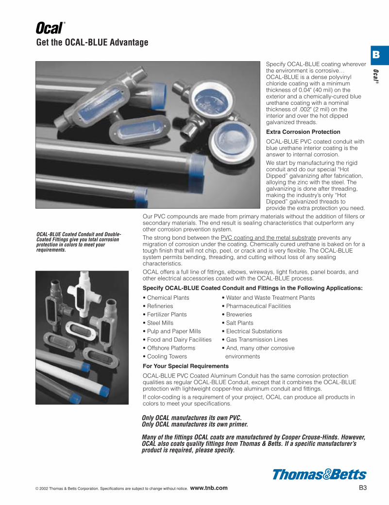
OCAL-BLUE Coated Conduit and Double-Coated Fittings give you total corrosionprotection in colors to meet yourrequirements.
Get the OCAL-BLUE Advantage
Specify OCAL-BLUE coating whereverthe environment is corrosive…OCAL-BLUE is a dense polyvinylchloride coating with a minimumthickness of 0.04" (40 mil) on theexterior and a chemically-cured blueurethane coating with a nominalthickness of .002" (2 mil) on theinterior and over the hot dippedgalvanized threads.
Extra Corrosion Protection
OCAL-BLUE PVC coated conduit withblue urethane interior coating is theanswer to internal corrosion.We start by manufacturing the rigidconduit and do our special “HotDipped” galvanizing after fabrication,alloying the zinc with the steel. Thegalvanizing is done after threading,making the industry’s only “HotDipped” galvanized threads toprovide the extra protection you need.
Our PVC compounds are made from primary materials without the addition of fillers orsecondary materials. The end result is sealing characteristics that outperform anyother corrosion prevention system.The strong bond between the PVC coating and the metal substrate prevents anymigration of corrosion under the coating. Chemically cured urethane is baked on for atough finish that will not chip, peel, or crack and is very flexible. The OCAL-BLUEsystem permits bending, threading, and cutting without loss of any sealingcharacteristics.OCAL offers a full line of fittings, elbows, wireways, light fixtures, panel boards, andother electrical accessories coated with the OCAL-BLUE process.
Specify OCAL-BLUE Coated Conduit and Fittings in the Following Applications:
• Chemical Plants • Water and Waste Treatment Plants• Refineries • Pharmaceutical Facilities• Fertilizer Plants • Breweries• Steel Mills • Salt Plants• Pulp and Paper Mills • Electrical Substations• Food and Dairy Facilities • Gas Transmission Lines• Offshore Platforms • And, many other corrosive• Cooling Towers environments
For Your Special Requirements
OCAL-BLUE PVC Coated Aluminum Conduit has the same corrosion protectionqualities as regular OCAL-BLUE Conduit, except that it combines the OCAL-BLUEprotection with lightweight copper-free aluminum conduit and fittings.If color-coding is a requirement of your project, OCAL can produce all products incolors to meet your specifications.
Only OCAL manufactures its own PVC.Only OCAL manufactures its own primer.
Many of the fittings OCAL coats are manufactured by Cooper Crouse-Hinds. However,OCAL also coats quality fittings from Thomas & Betts. If a specific manufacturer’sproduct is required, please specify.
© 2002 Thomas & Betts Corporation. Specifications are subject to change without notice. www.tnb.com B3
Ocal®
B
412031.B01 OCAL 3/5 3/13/03 5:01 PM Page 3
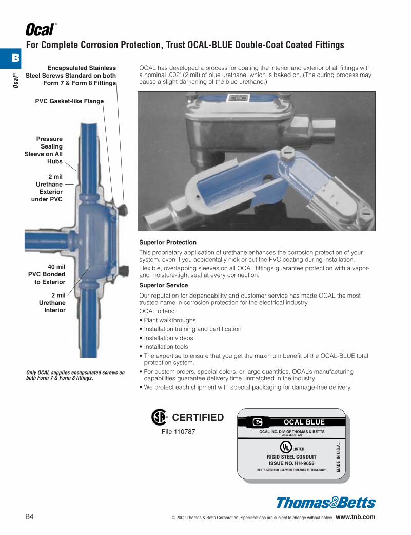
OCAL has developed a process for coating the interior and exterior of all fittings witha nominal .002" (2 mil) of blue urethane, which is baked on. (The curing process maycause a slight darkening of the blue urethane.)
Superior Protection
This proprietary application of urethane enhances the corrosion protection of yoursystem, even if you accidentally nick or cut the PVC coating during installation.Flexible, overlapping sleeves on all OCAL fittings guarantee protection with a vapor-and moisture-tight seal at every connection.
Superior Service
Our reputation for dependability and customer service has made OCAL the mosttrusted name in corrosion protection for the electrical industry.OCAL offers:• Plant walkthroughs• Installation training and certification• Installation videos• Installation tools• The expertise to ensure that you get the maximum benefit of the OCAL-BLUE total
protection system.• For custom orders, special colors, or large quantities, OCAL’s manufacturing
capabilities guarantee delivery time unmatched in the industry.• We protect each shipment with special packaging for damage-free delivery.
2 milUrethane
Interior
40 milPVC Bonded
to Exterior
PressureSealing
Sleeve on AllHubs
2 milUrethaneExterior
under PVC
PVC Gasket-like Flange
Encapsulated StainlessSteel Screws Standard on both
Form 7 & Form 8 Fittings
For Complete Corrosion Protection, Trust OCAL-BLUE Double-Coat Coated Fittings
Only OCAL supplies encapsulated screws onboth Form 7 & Form 8 fittings.
B4 © 2002 Thomas & Betts Corporation. Specifications are subject to change without notice. www.tnb.com
Ocal
®
® CERTIFIEDFile 110787
RESTRICTED FOR USE WITH THREADED FITTINGS ONLY.
RIGID STEEL CONDUITISSUE NO. HH-9658
LISTED
MAD
E IN
U.S
.A.
OCAL INC. DIV. OF THOMAS & BETTSJonesboro, AR
OCAL BLUE
B
412031.B01 OCAL 3/5 3/13/03 5:01 PM Page 4

• The conduit is PVC Coated Steel.• Blue urethane coating over threads.• A minimum .040" (40 mil) PVC coating on the exterior.• A nominal .002" (2 mil) blue urethane on the interior.• Color coded thread protectors.• Couplings shipped with conduit are packaged separately.
OCAL-BLUE ConduitOutside Outside Nominal Nominal Nominal Minimum
Size Diameter Diameter Wall Thickness Wall Thickness Inside Cross Section Length Without WeightInches Steel Only With PVC Steel Only With PVC Diameter Area in Square Couplings Per Foot
Metric Size Inches Inches Inches Inches Inches Inches Feet PoundsDesignator* Millimeters Millimeters Millimeters Millimeters Millimeters Millimeters Meters Kilograms
d .840 .920 .104 .144 .632 .304 9' 11b" .7916 21.3 23.3 2.64 3.556 16.1 7.72 3.03 35.83
f 1.050 1.130 .107 2.71 .836 .533 9' 11b" 1.0521 26.7 28.7 2.71 3.73 21.2 13.53 3.03 47.63
1 1.315 1.395 .126 .166 1.063 .864 9' 11" 1.5327 33.4 35.4 3.20 4.21 27.0 21.94 3.02 69.40
1b 1.660 1.740 .133 .173 1.394 1.495 9' 11" 2.0135 42.2 44.1 3.37 4.39 35.4 37.97 3.02 91.17
1d 1.900 1.980 .138 .178 1.624 2.036 9' 11" 2.4041 48.3 50.2 3.50 4.52 41.2 51.71 3.02 112.95
2 2.375 2.455 .146 .186 2.083 3.355 9' 11" 3.3253 60.3 62.3 3.70 4.72 52.9 85.21 3.02 150.60
2d 2.875 2.955 .193 .233 2.489 4.788 9' 10d" 5.2763 73.0 75.0 4.90 5.91 63.2 121.61 3.01 239.05
3d 3.500 3.580 .205 .245 3.090 7.393 9' 10d" 6.8378 88.9 90.9 5.20 6.22 78.5 187.78 3.01 309.63
3 4.000 4.080 .215 .255 3.57 9.866 9' 10b" 8.3191 101.6 103.6 5.46 6.47 90.7 250.59 3.00 376.94
4 4.500 4.580 .225 .265 4.05 12.730 9' 10b" 9.73103 114.3 116.3 5.71 6.73 102.9 323.34 3.00 441.04
5 5.563 5.643 .245 .285 5.073 20.006 9' 10" 13.14129 141.3 143.3 6.22 7.23 128.9 508.15 3.00 595.85
6 6.625 6.705 .266 .306 6.093 28.891 9' 10" 17.46155 168.3 170.3 6.75 .777 154.8 733.83 3.00 791.67
NOTE – Inches and Pounds indicated in bold face typeMetric measure is directly below bold face type
*Metric size designator (ANSI C80.1-1994).
OCAL-BLUE Steel Conduit
© 2002 Thomas & Betts Corporation. Specifications are subject to change without notice. www.tnb.com B5
Ocal®
® CERTIFIEDFile 110787
RESTRICTED FOR USE WITH THREADED FITTINGS ONLY.
RIGID STEEL CONDUITISSUE NO. HH-9658
LISTED
MAD
E IN
U.S
.A.
OCAL INC. DIV. OF THOMAS & BETTSJonesboro, AR
OCAL BLUE
B
412031.B01 OCAL 3/5 3/13/03 5:01 PM Page 5
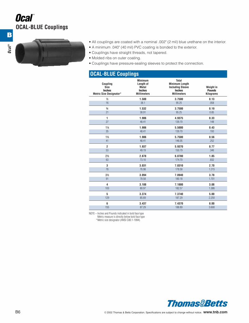
• All couplings are coated with a nominal .002" (2 mil) blue urethane on the interior.• A minimum .040" (40 mil) PVC coating is bonded to the exterior.• Couplings have straight threads, not tapered.• Molded ribs on outer coating.• Couplings have pressure-sealing sleeves to protect the connection.
OCAL-BLUE CouplingsMinimum Total
Coupling Length of Minimum LengthSize Metal Including Sleeve Weight in
Inches Inches Inches PoundsMetric Size Designator* Millimeters Millimeters Kilograms
d 1.500 3.7500 0.1316 38.1 95.25 .058
f 1.532 3.7500 0.1921 38.91 95.25 0.85
1 1.906 4.9375 0.3327 48.41 139.70 .148
1b 1.906 5.5000 0.4335 48.41 139.70 .193
1d 1.906 5.7500 0.5641 48.41 146.05 .252
2 1.937 5.9370 0.7753 49.19 150.79 .346
2d 2.878 6.8780 1.8563 73.10 174.70 .832
3 3.031 7.0310 2.7078 76.98 178.58 1.215
3d 3.094 7.0940 3.7891 78.58 180.18 1.701
4 3.188 7.1880 3.08103 80.97 182.57 1.386
5 3.374 7.3740 5.00129 85.69 187.29 2.250
6 3.437 7.4370 8.00155 87.29 188.89 3.600
NOTE – Inches and Pounds indicated in bold face typeMetric measure is directly below bold face type
*Metric size designator (ANSI C80.1-1994).
OCAL-BLUE Couplings
B6 © 2002 Thomas & Betts Corporation. Specifications are subject to change without notice. www.tnb.com
Ocal
®
B
412031.B01 OCAL 3/5 3/13/03 5:01 PM Page 6
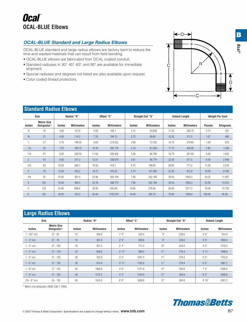
OCAL-BLUE Standard and Large Radius Elbows
OCAL-BLUE standard and large radius elbows are factory bent to reduce thetime and wasted materials that can result from field bending.• OCAL-BLUE elbows are fabricated from OCAL coated conduit.• Standard radiuses in 30°, 45°, 60°, and 90° are available for immediate
shipment.• Special radiuses and degrees not listed are also available upon request.• Color coded thread protectors.
Standard Radius ElbowsSize Radius “R” Offset “C” Straight End “D” Unbent Length Weight Per Each
Metric SizeInches Designator* Inches Millimeters Inches Millimeters Inches Millimeters Inches Millimeters Pounds Kilograms
d 16 4.00 101.6 6.50 165.1 2.12 53.848 11.25 285.75 0.73 .331
f 21 4.50 114.3 7.25 184.15 2.75 69.85 12.50 317.5 1.07 .485
1 27 5.75 146.05 8.63 219.202 2.88 73.152 14.75 374.65 1.93 .875
1b 35 7.25 184.15 10.44 265.176 3.19 81.026 17.75 450.85 2.85 1.293
1d 41 8.25 209.55 11.63 295.402 3.38 84.785 19.75 501.65 4.26 1.932
2 53 9.50 241.3 13.31 338.074 3.81 96.774 22.50 571.5 6.50 2.948
2d 63 10.50 266.7 16.50 419.1 5.75 146.05 28.00 711.2 11.50 5.216
3 78 13.00 330.2 18.75 476.25 5.79 147.066 32.00 812.8 18.00 8.165
3d 91 15.00 381.0 22.96 583.184 7.96 202.184 39.50 1003.3 26.25 11.907
4 103 16.00 406.4 23.18 588.772 7.96 202.184 39.50 1003.3 32.00 14.515
5 129 24.00 609.6 34.90 835.66 10.90 276.86 59.50 1511.3 70.00 31.752
6 155 30.00 762.0 43.44 1103.376 14.40 365.76 76.00 1930.4 100.00 45.36
OCAL-BLUE Elbows
Large Radius ElbowsSize Radius “R” Offset “C” Straight End “D” Unbent Length
Metric SizeInches Designator* Inches Millimeters Inches Millimeters Inches Millimeters Inches Millimeters
1 - 2d" incl. 27 - 63 12 304.8 1' 9" 533.4 9" 228.6 3' 0" 914.4
1 - 3" incl. 27 - 78 15 381.0 2' 0" 609.6 9" 228.6 3' 6" 1066.8
1 - 4" incl. 27 - 103 18 457.2 2' 4" 711.2 10" 254.0 4' 0" 1219.2
1 - 5" incl. 27 - 129 24 609.6 2' 11" 889.0 11" 279.4 4' 11" 1498.6
1 - 6" incl. 27 - 155 30 762.0 3' 5" 1041.4 11" 279.4 5' 9" 1752.6
1 - 6" incl. 27 - 155 36 914.4 3' 11" 1193.8 11" 279.4 6' 6" 1981.2
1 - 6" incl. 27 - 155 42 1066.8 4' 6" 1371.6 12" 304.8 7' 6" 2286.0
1 - 6" incl. 27 - 155 48 1219.2 5' 0" 1524.0 12" 304.8 8' 6" 2590.8
2d - 6" incl. 63 - 155 60 1524.0 6' 0" 1828.8 12" 304.8 9' 10" 2997.2
* Metric size designator (ANSI C80.1-1994).
© 2002 Thomas & Betts Corporation. Specifications are subject to change without notice. www.tnb.com B7
Ocal®
B
412031.B01 OCAL 3/5 3/13/03 5:01 PM Page 7
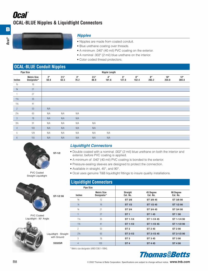
OCAL-BLUE Conduit NipplesPipe Size Nipple Length
Metric Size 2" 2d" 3" 3d" 4" 5" 6"` 8"` 10" 12"Inches Designator* 50.8 63.5 76.2 88.9 101.6 127.0 152.4 203.2 254.0 304.8
d 16
f 21
1 27
1b 35
1d 41
2 53 N/A
2d 63 N/A N/A N/A
3 78 N/A N/A N/A
3d 91 N/A N/A N/A N/A
4 103 N/A N/A N/A N/A
5 129 N/A N/A N/A N/A N/A
6 155 N/A N/A N/A N/A N/A
Liquidtight Connectors
• Double coated with a nominal .002" (2 mil) blue urethane on both the interior andexterior, before PVC coating is applied.
• A minimum of .040" (40 mil) PVC coating is bonded to the exterior.• Pressure-sealing sleeves are designed to protect the connection.• Available in straight, 45°, and 90°.• Ocal uses genuine T&B liquidtight fittings to insure quality installations.
Liquidtight ConnectorsPipe Size
Metric Size Straight 45 Degree 90 DegreeInches Designator* Cat. No. Cat. No. Cat. No.
c 12 ST 3/8 ST 3/8 45 ST 3/8 90
d 16 ST 1/2 ST 1/2 45 ST 1/2 90
f 21 ST 3/4 ST 3/4 45 ST 3/4 90
1 27 ST 1 ST 1 45 ST 1 90
1b 35 ST 1-1/4 ST 1-1/4 45 ST 1-1/4 90
1d 41 ST 1-1/2 ST 1-1/2 45 ST 1-1/2 90
2 53 ST 2 ST 2 45 ST 2 90
2d 63 ST 2-1/2 ST 2-1/2 45 ST 2-1/2 90
3 78 ST 3 ST 3 45 ST 3 90
4 103 ST 4 ST 4 45 ST 4 90
* Metric size designator (ANSI C80.1-1994).
Liquidtight - Straightwith Ground
PVC CoatedStraight Liquidtight
Nipples
• Nipples are made from coated conduit.• Blue urethane coating over threads.• A minimum .040" (40 mil) PVC coating on the exterior.• A nominal .002" (2 mil) blue urethane on the interior.• Color coded thread protectors.
OCAL-BLUE Nipples & Liquidtight Connectors
B8 © 2002 Thomas & Betts Corporation. Specifications are subject to change without notice. www.tnb.com
ST-1/2
5332GR
ST-1/2 90
PVC CoatedLiquidtight - 90° Angle
Ocal
®
B
412031.B01 OCAL 3/5 3/13/03 5:01 PM Page 8
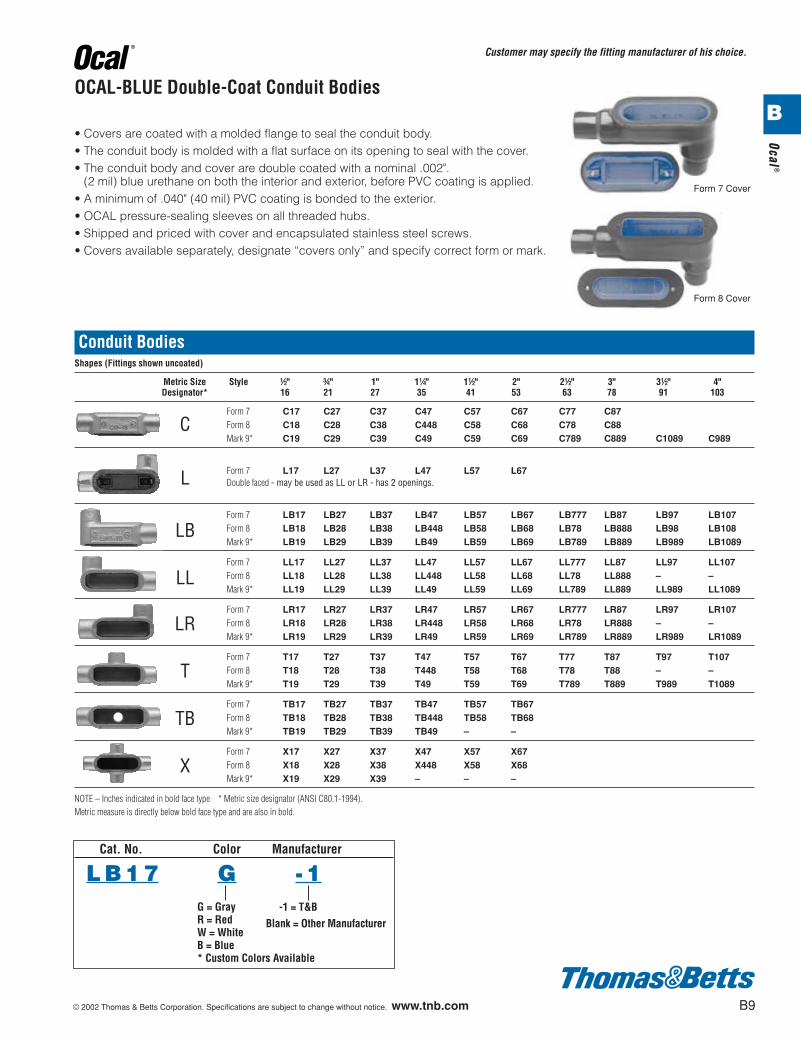
Conduit BodiesShapes (Fittings shown uncoated)
Metric Size Style d" f" 1" 1b" 1d" 2" 2d" 3" 3d" 4"Designator* 16 21 27 35 41 53 63 78 91 103
Form 7 C17 C27 C37 C47 C57 C67 C77 C87
C Form 8 C18 C28 C38 C448 C58 C68 C78 C88Mark 9* C19 C29 C39 C49 C59 C69 C789 C889 C1089 C989
L Form 7 L17 L27 L37 L47 L57 L67Double faced - may be used as LL or LR - has 2 openings.
Form 7 LB17 LB27 LB37 LB47 LB57 LB67 LB777 LB87 LB97 LB107
LB Form 8 LB18 LB28 LB38 LB448 LB58 LB68 LB78 LB888 LB98 LB108Mark 9* LB19 LB29 LB39 LB49 LB59 LB69 LB789 LB889 LB989 LB1089
Form 7 LL17 LL27 LL37 LL47 LL57 LL67 LL777 LL87 LL97 LL107
LL Form 8 LL18 LL28 LL38 LL448 LL58 LL68 LL78 LL888 – –Mark 9* LL19 LL29 LL39 LL49 LL59 LL69 LL789 LL889 LL989 LL1089
Form 7 LR17 LR27 LR37 LR47 LR57 LR67 LR777 LR87 LR97 LR107
LR Form 8 LR18 LR28 LR38 LR448 LR58 LR68 LR78 LR888 – –Mark 9* LR19 LR29 LR39 LR49 LR59 LR69 LR789 LR889 LR989 LR1089
Form 7 T17 T27 T37 T47 T57 T67 T77 T87 T97 T107
T Form 8 T18 T28 T38 T448 T58 T68 T78 T88 – –Mark 9* T19 T29 T39 T49 T59 T69 T789 T889 T989 T1089
Form 7 TB17 TB27 TB37 TB47 TB57 TB67
TB Form 8 TB18 TB28 TB38 TB448 TB58 TB68Mark 9* TB19 TB29 TB39 TB49 – –
Form 7 X17 X27 X37 X47 X57 X67
X Form 8 X18 X28 X38 X448 X58 X68Mark 9* X19 X29 X39 – – –
NOTE – Inches indicated in bold face type * Metric size designator (ANSI C80.1-1994).Metric measure is directly below bold face type and are also in bold.
• Covers are coated with a molded flange to seal the conduit body.• The conduit body is molded with a flat surface on its opening to seal with the cover.• The conduit body and cover are double coated with a nominal .002".
(2 mil) blue urethane on both the interior and exterior, before PVC coating is applied.• A minimum of .040" (40 mil) PVC coating is bonded to the exterior.• OCAL pressure-sealing sleeves on all threaded hubs.• Shipped and priced with cover and encapsulated stainless steel screws.• Covers available separately, designate “covers only” and specify correct form or mark.
Form 7 Cover
OCAL-BLUE Double-Coat Conduit Bodies
Customer may specify the fitting manufacturer of his choice.
Form 8 Cover
© 2002 Thomas & Betts Corporation. Specifications are subject to change without notice. www.tnb.com B9
Ocal®
Cat. No. Color Manufacturer
L B 1 7 G - 1G = GrayR = RedW = WhiteB = Blue* Custom Colors Available
-1 = T&BBlank = Other Manufacturer
B
412031.B01 OCAL 3/5 3/13/03 5:01 PM Page 9
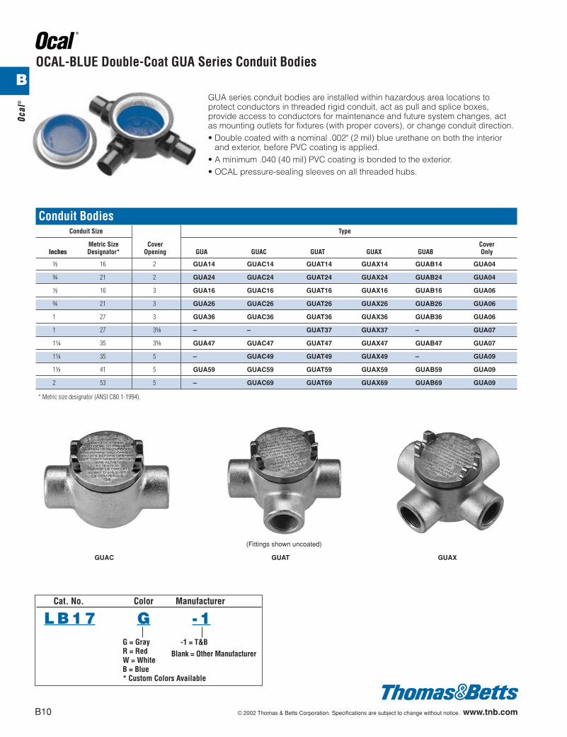
Conduit BodiesConduit Size Type
Metric Size Cover CoverInches Designator* Opening GUA GUAC GUAT GUAX GUAB Only
d 16 2 GUA14 GUAC14 GUAT14 GUAX14 GUAB14 GUA04
f 21 2 GUA24 GUAC24 GUAT24 GUAX24 GUAB24 GUA04
d 16 3 GUA16 GUAC16 GUAT16 GUAX16 GUAB16 GUA06
f 21 3 GUA26 GUAC26 GUAT26 GUAX26 GUAB26 GUA06
1 27 3 GUA36 GUAC36 GUAT36 GUAX36 GUAB36 GUA06
1 27 3e – – GUAT37 GUAX37 – GUA07
1b 35 3e GUA47 GUAC47 GUAT47 GUAX47 GUAB47 GUA07
1b 35 5 – GUAC49 GUAT49 GUAX49 – GUA09
1d 41 5 GUA59 GUAC59 GUAT59 GUAX59 GUAB59 GUA09
2 53 5 – GUAC69 GUAT69 GUAX69 GUAB69 GUA09
** Metric size designator (ANSI C80.1-1994).
GUAC GUAT GUAX
GUA series conduit bodies are installed within hazardous area locations toprotect conductors in threaded rigid conduit, act as pull and splice boxes,provide access to conductors for maintenance and future system changes, actas mounting outlets for fixtures (with proper covers), or change conduit direction.• Double coated with a nominal .002" (2 mil) blue urethane on both the interior
and exterior, before PVC coating is applied.• A minimum .040 (40 mil) PVC coating is bonded to the exterior.• OCAL pressure-sealing sleeves on all threaded hubs.
(Fittings shown uncoated)
OCAL-BLUE Double-Coat GUA Series Conduit Bodies
B10 © 2002 Thomas & Betts Corporation. Specifications are subject to change without notice. www.tnb.com
Ocal
®
Cat. No. Color Manufacturer
L B 1 7 G - 1G = GrayR = RedW = WhiteB = Blue* Custom Colors Available
-1 = T&BBlank = Other Manufacturer
B
412031.B01 OCAL 3/5 3/13/03 5:01 PM Page 10
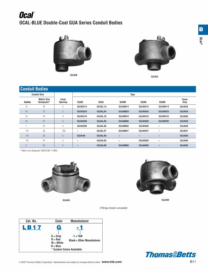
GUAN
GUAD
GUAW
GUAB
(Fittings shown uncoated)
OCAL-BLUE Double-Coat GUA Series Conduit Bodies
Conduit BodiesConduit Size Type
Metric Size Cover CoverInches Designator* Opening GUAD GUAL GUAM GUAN GUAW Only
d 16 2 GUAD14 GUAL14 GUAM14 GUAN14 GUAW14 GUA04
f 21 2 GUAD24 GUAL24 GUAM24 GUAN24 GUAW24 GUA04
d 16 3 GUAD16 GUAL16 GUAM16 GUAN16 GUAW16 GUA06
f 21 3 GUAD26 GUAL26 GUAM26 GUAN26 GUAW26 GUA06
1 27 3 GUAD36 GUAL36 GUAM36 GUAN36 – GUA06
1b 35 3e – GUAL47 GUAM47 GUAN47 – GUA07
1b 35 5 GUA49 GUAL49 – – – GUA09
1d 41 5 – GUAL59 – GUAN59 – GUA09
2 53 5 – GUAL69 GUAM69 GUAN69 – GUA09
** Metric size designator (ANSI C80.1-1994).
© 2002 Thomas & Betts Corporation. Specifications are subject to change without notice. www.tnb.com B11
Ocal®
Cat. No. Color Manufacturer
L B 1 7 G - 1G = GrayR = RedW = WhiteB = Blue* Custom Colors Available
-1 = T&BBlank = Other Manufacturer
B
412031.B01 OCAL 3/5 3/13/03 5:01 PM Page 11
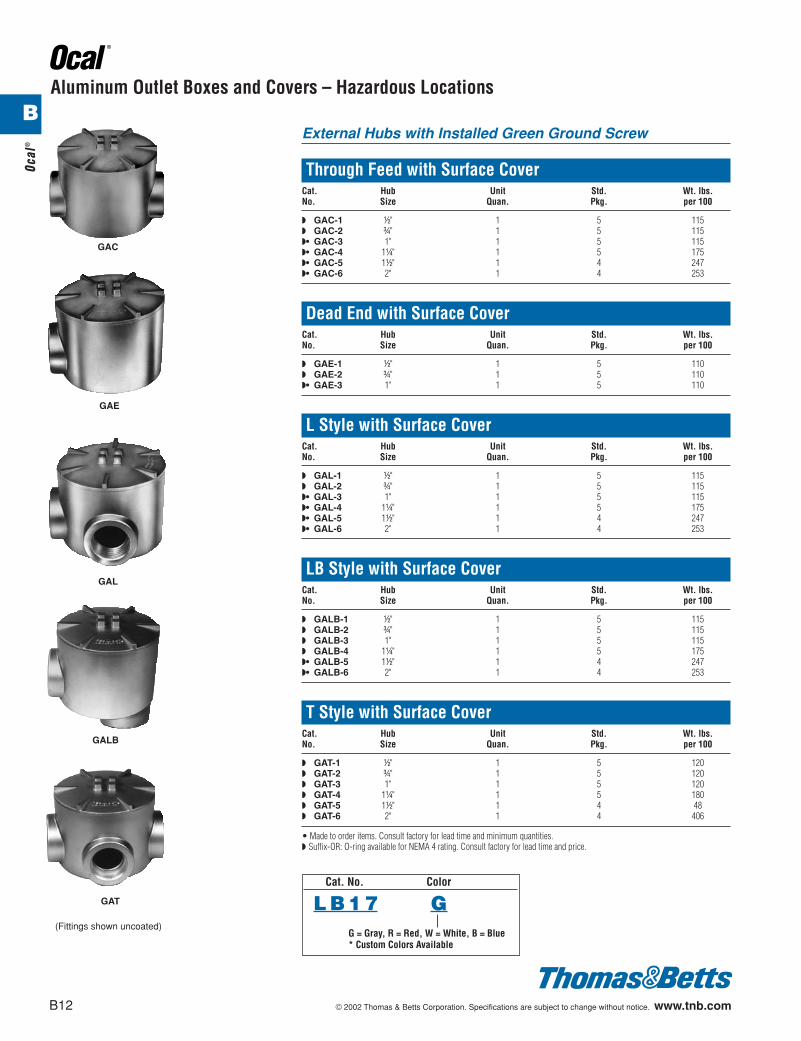
Aluminum Outlet Boxes and Covers – Hazardous Locations
External Hubs with Installed Green Ground Screw
Through Feed with Surface CoverCat. Hub Unit Std. Wt. lbs.No. Size Quan. Pkg. per 100
◗ GAC-1 d" 1 5 115◗ GAC-2 f" 1 5 115◗• GAC-3 1" 1 5 115◗• GAC-4 1b" 1 5 175◗• GAC-5 1d" 1 4 247◗• GAC-6 2" 1 4 253
Dead End with Surface CoverCat. Hub Unit Std. Wt. lbs.No. Size Quan. Pkg. per 100
◗ GAE-1 d" 1 5 110◗ GAE-2 f" 1 5 110◗• GAE-3 1" 1 5 110
L Style with Surface CoverCat. Hub Unit Std. Wt. lbs.No. Size Quan. Pkg. per 100
◗ GAL-1 d" 1 5 115◗ GAL-2 f" 1 5 115◗• GAL-3 1" 1 5 115◗• GAL-4 1b" 1 5 175◗• GAL-5 1d" 1 4 247◗• GAL-6 2" 1 4 253
LB Style with Surface CoverCat. Hub Unit Std. Wt. lbs.No. Size Quan. Pkg. per 100
◗ GALB-1 d" 1 5 115◗ GALB-2 f" 1 5 115◗ GALB-3 1" 1 5 115◗ GALB-4 1b" 1 5 175◗• GALB-5 1d" 1 4 247◗• GALB-6 2" 1 4 253
T Style with Surface CoverCat. Hub Unit Std. Wt. lbs.No. Size Quan. Pkg. per 100
◗ GAT-1 d" 1 5 120◗ GAT-2 f" 1 5 120◗ GAT-3 1" 1 5 120◗ GAT-4 1b" 1 5 180◗ GAT-5 1d" 1 4 48◗ GAT-6 2" 1 4 406
• Made to order items. Consult factory for lead time and minimum quantities.◗ Suffix-OR: O-ring available for NEMA 4 rating. Consult factory for lead time and price.
GAC
GAE
GAL
GALB
GAT
B12 © 2002 Thomas & Betts Corporation. Specifications are subject to change without notice. www.tnb.com
(Fittings shown uncoated)
Ocal
®
Cat. No. Color
L B 1 7 GG = Gray, R = Red, W = White, B = Blue* Custom Colors Available
B
412031.B01 OCAL 3/5 3/13/03 5:02 PM Page 12
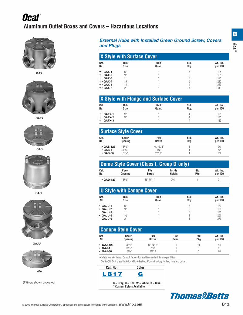
Aluminum Outlet Boxes and Covers – Hazardous Locations
External Hubs with Installed Green Ground Screw, Coversand Plugs
X Style with Surface CoverCat. Hub Unit Std. Wt. lbs.No. Size Quan. Pkg. per 100
† GAX-1 d" 1 5 125† GAX-2 f" 1 5 125† GAX-3 1" 1 5 125† • GAX-4 1b" 1 5 210† • GAX-5 1d" 1 4 257† • GAX-6 2" 1 4 413
X Style with Flange and Surface CoverCat. Hub Unit Std. Wt. lbs.No. Size Quan. Pkg. per 100
† GAFX-1 d" 1 4 135† GAFX-2 f" 1 4 135† GAFX-3 1" 1 4 135
Surface Style CoverCat. Cover Fits Std. Wt. lbs.No. Opening Boxes Pkg. per 100
• GAS-123 3W" d", f", 1" 1 36• GAS-4 3C" 1b" 1 52• GAS-56 5i" 1d", 2" 1 69
Dome Style Cover (Class I, Group D only)Cat. Cover Fits Inside Std. Wt. lbs.No. Opening Boxes Height Pkg. per 100
• GAD-123 3W" d", f", 1" 2e" 1 71
U Style with Canopy CoverCat. Hub Unit Std. Wt. lbs.No. Size Quan. Pkg. per 100
• GAJU-1 d" 1 5 130• GAJU-2 f" 1 5 130
GAJU-3 1" 1 5 130• GAJU-5 1d" 1 1 267
GAJU-6 2" 1 1 273
Canopy Style CoverCat. Cover Fits Unit Std. Wt. lbs.No. Opening Boxes Quan. Pkg. per 100
• GAJ-123 3W" d", f", 1" 1 10 44• GAJ-4 3C" 1b" 1 5 61• GAJ-56 5i" 1d", 2 1 5 78
• Made to order items. Consult factory for lead time and minimum quantities.† Suffix-OR: O-ring available for NEMA 4 rating. Consult factory for lead time and price.
GAX
GAFX
GAS
GAD
© 2002 Thomas & Betts Corporation. Specifications are subject to change without notice. www.tnb.com B13
Ocal®
Cat. No. Color
L B 1 7 GG = Gray, R = Red, W = White, B = Blue* Custom Colors Available
GAJU
GAJ
(Fittings shown uncoated)
B
412031.B01 OCAL 3/5 3/13/03 5:02 PM Page 13
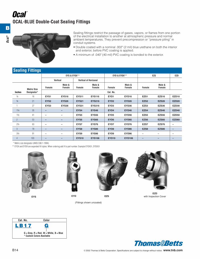
OCAL-BLUE Double-Coat Sealing Fittings
Sealing fittings restrict the passage of gases, vapors, or flames from one portionof the electrical installation to another at atmospheric pressure and normalambient temperatures. They prevent precompression or “pressure piling” inconduit systems.• Double coated with a nominal .002" (2 mil) blue urethane on both the interior
and exterior, before PVC coating is applied.• A minimum of .040" (40 mil) PVC coating is bonded to the exterior.
EYS EYD EZS
(Fittings shown uncoated)
Sealing FittingsEYS & EYSX** EYD & EYDX** EZS EZD
Vertical Vertical of Horizonal
Male & Male & Male & Male &
Metric SizeFemale Female Female Female Female Female Female Female
Inches Designator* Cat. No.
d 16 EYS1 EYS16 EYS11 EYS116 EYD1 EYD16 EZS1 EZS16 EZD10
f 21 EYS2 EYS26 EYS21 EYS216 EYD2 EYD26 EZS2 EZS26 EZD20
1 27 EYS3 EYS36 EYS31 EYS316 EYD3 EYD36 EZS3 EZS36 EZD30
1b 35 – – EYS4 EYS46 EYD4 EYD46 EZS4 EZS46 EZD40
1d 41 – – EYS5 EYS56 EYD5 EYD56 EZS5 EZS56 EZD50
2 53 – – EYS6 EYS66 EYD6 EYD66 EZS6 EZS66 EZD60
2d 63 – – EYS7 EYS76 EYD7 EYD76 EZS7 EZS76 –
3 78 – – EYS8 EYS86 EYD8 EYD86 EZS8 EZS86 –
3d 91 – – EYS9 EYS96 EYD9 EYD96 – – –
4 103 – – EYS10 EYS106 EYD10 EYD106 – – –
** Metric size designator (ANSI C80.1-1994).** EYSX and EYDX are expanded fill styles. When ordering add X to part number. Example EYSX31, EYDX31
EZDwith Inspection Cover
B14 © 2002 Thomas & Betts Corporation. Specifications are subject to change without notice. www.tnb.com
Ocal
®
Cat. No. Color
L B 1 7 GG = Gray, R = Red, W = White, B = Blue* Custom Colors Available
B
412031.B01 OCAL 3/5 3/13/03 5:02 PM Page 14
© 2002 Thomas & Betts Corporation. Specifications are subject to change without notice. www.tnb.com B15
Ocal®
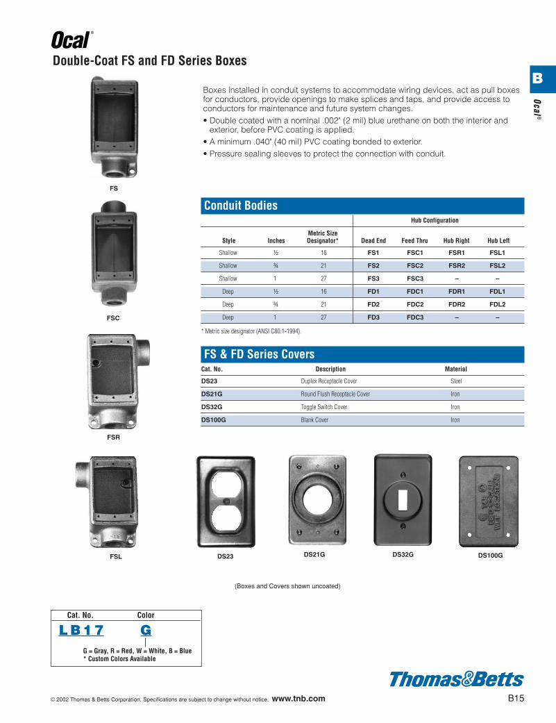
Double-Coat FS and FD Series Boxes
Conduit BodiesHub Configuration
Metric SizeStyle Inches Designator* Dead End Feed Thru Hub Right Hub Left
Shallow d 16 FS1 FSC1 FSR1 FSL1
Shallow f 21 FS2 FSC2 FSR2 FSL2
Shallow 1 27 FS3 FSC3 – –
Deep d 16 FD1 FDC1 FDR1 FDL1
Deep f 21 FD2 FDC2 FDR2 FDL2
Deep 1 27 FD3 FDC3 – –
* Metric size designator (ANSI C80.1-1994).
FS & FD Series CoversCat. No. Description Material
DS23 Duplex Receptacle Cover Steel
DS21G Round Flush Receptacle Cover Iron
DS32G Toggle Switch Cover Iron
DS100G Blank Cover Iron
Boxes installed in conduit systems to accommodate wiring devices, act as pull boxesfor conductors, provide openings to make splices and taps, and provide access toconductors for maintenance and future system changes.• Double coated with a nominal .002" (2 mil) blue urethane on both the interior and
exterior, before PVC coating is applied.• A minimum .040" (40 mil) PVC coating bonded to exterior.• Pressure sealing sleeves to protect the connection with conduit.
FS
DS23 DS21G DS32G DS100G
FSC
FSR
FSL
(Boxes and Covers shown uncoated)
Cat. No. Color
L B 1 7 GG = Gray, R = Red, W = White, B = Blue* Custom Colors Available
B
412031.B01 OCAL 3/5 3/13/03 5:02 PM Page 15
B16 © 2002 Thomas & Betts Corporation. Specifications are subject to change without notice. www.tnb.com
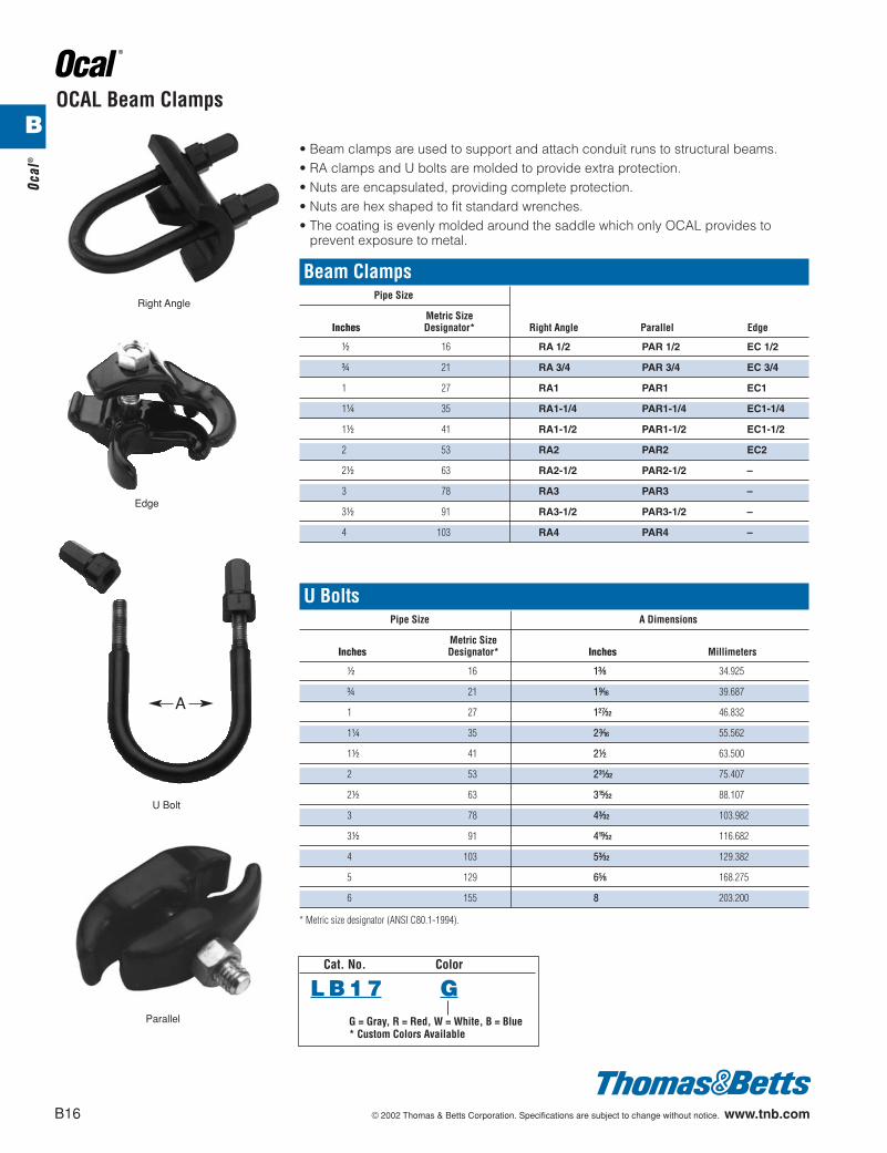
U BoltsPipe Size A Dimensions
Metric SizeInches Designator* Inches Millimeters
d 16 1c 34.925
f 21 1l 39.687
1 27 1B 46.832
1b 35 2i 55.562
1d 41 2d 63.500
2 53 2O 75.407
2d 63 3v 88.107
3 78 4p 103.982
3d 91 4x 116.682
4 103 5p 129.382
5 129 6e 168.275
6 155 8 203.200
* Metric size designator (ANSI C80.1-1994).
OCAL Beam Clamps
A
Right Angle
Parallel
Edge
U Bolt
• Beam clamps are used to support and attach conduit runs to structural beams.• RA clamps and U bolts are molded to provide extra protection.• Nuts are encapsulated, providing complete protection.• Nuts are hex shaped to fit standard wrenches.• The coating is evenly molded around the saddle which only OCAL provides to
prevent exposure to metal.
Beam ClampsPipe Size
Metric SizeInches Designator* Right Angle Parallel Edge
d 16 RA 1/2 PAR 1/2 EC 1/2
f 21 RA 3/4 PAR 3/4 EC 3/4
1 27 RA1 PAR1 EC1
1b 35 RA1-1/4 PAR1-1/4 EC1-1/4
1d 41 RA1-1/2 PAR1-1/2 EC1-1/2
2 53 RA2 PAR2 EC2
2d 63 RA2-1/2 PAR2-1/2 –
3 78 RA3 PAR3 –
3d 91 RA3-1/2 PAR3-1/2 –
4 103 RA4 PAR4 –
Cat. No. Color
L B 1 7 GG = Gray, R = Red, W = White, B = Blue* Custom Colors Available
Ocal
®
B
412031.B01 OCAL 3/5 3/13/03 5:02 PM Page 16
© 2002 Thomas & Betts Corporation. Specifications are subject to change without notice. www.tnb.com B17
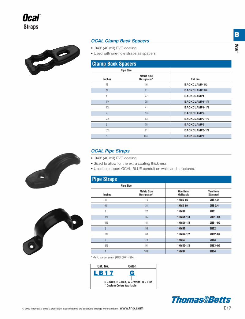
OCAL Clamp Back Spacers
• .040" (40 mil) PVC coating.• Used with one-hole straps as spacers.
Clamp Back SpacersPipe Size
Metric SizeInches Designator* Cat. No.
d 16 BACKCLAMP 1/2
f 21 BACKCLAMP 3/4
1 27 BACKCLAMP1
1b 35 BACKCLAMP1-1/4
1d 41 BACKCLAMP1-1/2
2 53 BACKCLAMP2
2d 63 BACKCLAMP2-1/2
3 78 BACKCLAMP3
3d 91 BACKCLAMP3-1/2
4 103 BACKCLAMP4
OCAL Pipe Straps
• .040" (40 mil) PVC coating.• Sized to allow for the extra coating thickness.• Used to support OCAL-BLUE conduit on walls and structures.
Pipe StrapsPipe Size
Metric Size One Hole Two HoleInches Designator* Malleable Stamped
d 16 1HMS 1/2 2HS 1/2
f 21 1HMS 3/4 2HS 3/4
1 27 1HMS1 2HS1
1b 35 1HMS1-1/4 2HS1-1/4
1d 41 1HMS1-1/2 2HS1-1/2
2 53 1HMS2 2HS2
2d 63 1HMS2-1/2 2HS2-1/2
3 78 1HMS3 2HS3
3d 91 1HMS3-1/2 2HS3-1/2
4 103 1HMS4 2HS4
* Metric size designator (ANSI C80.1-1994).
Straps
Cat. No. Color
L B 1 7 GG = Gray, R = Red, W = White, B = Blue* Custom Colors Available
Ocal®
B
412031.B01 OCAL 3/5 3/13/03 5:02 PM Page 17
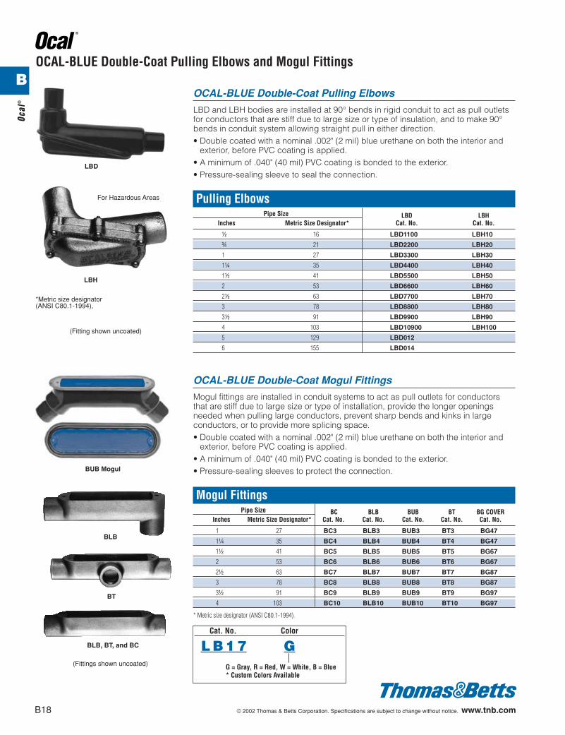
OCAL-BLUE Double-Coat Mogul Fittings
Mogul fittings are installed in conduit systems to act as pull outlets for conductorsthat are stiff due to large size or type of installation, provide the longer openingsneeded when pulling large conductors, prevent sharp bends and kinks in largeconductors, or to provide more splicing space.• Double coated with a nominal .002" (2 mil) blue urethane on both the interior and
exterior, before PVC coating is applied.• A minimum of .040" (40 mil) PVC coating is bonded to the exterior.• Pressure-sealing sleeves to protect the connection.
Mogul FittingsPipe Size BC BLB BUB BT BG COVER
Inches Metric Size Designator* Cat. No. Cat. No. Cat. No. Cat. No. Cat. No.
1 27 BC3 BLB3 BUB3 BT3 BG47
1b 35 BC4 BLB4 BUB4 BT4 BG47
1d 41 BC5 BLB5 BUB5 BT5 BG67
2 53 BC6 BLB6 BUB6 BT6 BG67
2d 63 BC7 BLB7 BUB7 BT7 BG87
3 78 BC8 BLB8 BUB8 BT8 BG87
3d 91 BC9 BLB9 BUB9 BT9 BG97
4 103 BC10 BLB10 BUB10 BT10 BG97
* Metric size designator (ANSI C80.1-1994).
OCAL-BLUE Double-Coat Pulling Elbows and Mogul Fittings
LBH
BT
BLB, BT, and BC
LBD
For Hazardous Areas
BUB Mogul
BLB
OCAL-BLUE Double-Coat Pulling Elbows
LBD and LBH bodies are installed at 90° bends in rigid conduit to act as pull outletsfor conductors that are stiff due to large size or type of insulation, and to make 90°bends in conduit system allowing straight pull in either direction.• Double coated with a nominal .002" (2 mil) blue urethane on both the interior and
exterior, before PVC coating is applied.• A minimum of .040" (40 mil) PVC coating is bonded to the exterior.• Pressure-sealing sleeve to seal the connection.
Pulling ElbowsPipe Size LBD LBH
Inches Metric Size Designator* Cat. No. Cat. No.
d 16 LBD1100 LBH10
f 21 LBD2200 LBH20
1 27 LBD3300 LBH30
1b 35 LBD4400 LBH40
1d 41 LBD5500 LBH50
2 53 LBD6600 LBH60
2d 63 LBD7700 LBH70
3 78 LBD8800 LBH80
3d 91 LBD9900 LBH90
4 103 LBD10900 LBH100
5 129 LBD012
6 155 LBD014
*Metric size designator (ANSI C80.1-1994),
(Fitting shown uncoated)
(Fittings shown uncoated)
B18 © 2002 Thomas & Betts Corporation. Specifications are subject to change without notice. www.tnb.com
Ocal
®
Cat. No. Color
L B 1 7 GG = Gray, R = Red, W = White, B = Blue* Custom Colors Available
B
412031.B01 OCAL 3/5 3/13/03 5:02 PM Page 18
© 2002 Thomas & Betts Corporation. Specifications are subject to change without notice. www.tnb.com B19
Ocal®
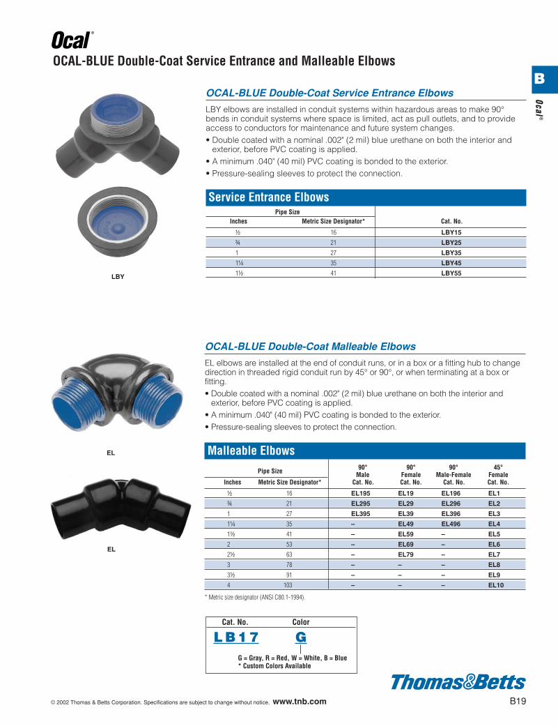
OCAL-BLUE Double-Coat Service Entrance Elbows
LBY elbows are installed in conduit systems within hazardous areas to make 90°bends in conduit systems where space is limited, act as pull outlets, and to provideaccess to conductors for maintenance and future system changes.• Double coated with a nominal .002" (2 mil) blue urethane on both the interior and
exterior, before PVC coating is applied.• A minimum .040" (40 mil) PVC coating is bonded to the exterior.• Pressure-sealing sleeves to protect the connection.
Service Entrance ElbowsPipe Size
Cat. No.Inches Metric Size Designator*
d 16 LBY15
f 21 LBY25
1 27 LBY35
1b 35 LBY45
1d 41 LBY55
OCAL-BLUE Double-Coat Service Entrance and Malleable Elbows
LBY
EL
EL
Cat. No. Color
L B 1 7 GG = Gray, R = Red, W = White, B = Blue* Custom Colors Available
OCAL-BLUE Double-Coat Malleable Elbows
EL elbows are installed at the end of conduit runs, or in a box or a fitting hub to changedirection in threaded rigid conduit run by 45° or 90°, or when terminating at a box orfitting.• Double coated with a nominal .002" (2 mil) blue urethane on both the interior and
exterior, before PVC coating is applied.• A minimum .040" (40 mil) PVC coating is bonded to the exterior.• Pressure-sealing sleeves to protect the connection.
Malleable ElbowsPipe Size 90° 90° 90° 45°
Male Female Male-Female FemaleInches Metric Size Designator* Cat. No. Cat. No. Cat. No. Cat. No.
d 16 EL195 EL19 EL196 EL1
f 21 EL295 EL29 EL296 EL2
1 27 EL395 EL39 EL396 EL3
1b 35 – EL49 EL496 EL4
1d 41 – EL59 – EL5
2 53 – EL69 – EL6
2d 63 – EL79 – EL7
3 78 – – – EL8
3d 91 – – – EL9
4 103 – – – EL10
* Metric size designator (ANSI C80.1-1994).
B
412031.B01 OCAL 3/5 3/13/03 5:02 PM Page 19
B20 © 2002 Thomas & Betts Corporation. Specifications are subject to change without notice. www.tnb.com
Ocal
®
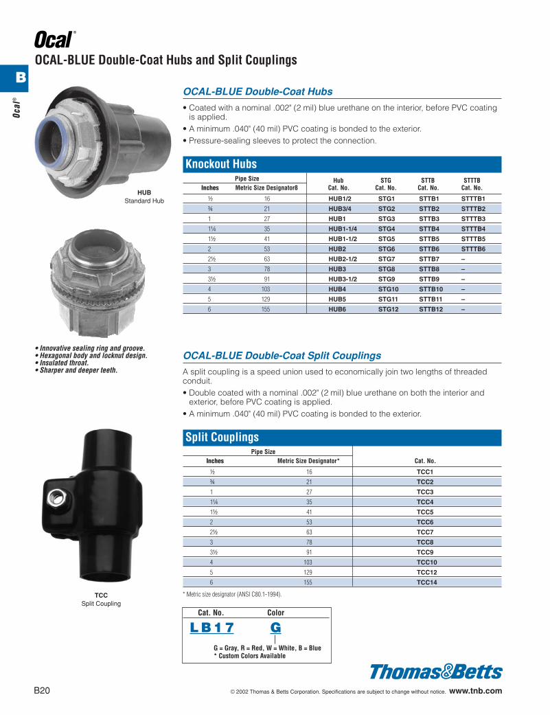
OCAL-BLUE Double-Coat Hubs and Split Couplings
HUBStandard Hub
TCCSplit Coupling
OCAL-BLUE Double-Coat Hubs
• Coated with a nominal .002" (2 mil) blue urethane on the interior, before PVC coatingis applied.
• A minimum .040" (40 mil) PVC coating is bonded to the exterior.• Pressure-sealing sleeves to protect the connection.
Knockout HubsPipe Size Hub STG STTB STTTB
Inches Metric Size Designator8 Cat. No. Cat. No. Cat. No. Cat. No.
d 16 HUB1/2 STG1 STTB1 STTTB1
f 21 HUB3/4 STG2 STTB2 STTTB2
1 27 HUB1 STG3 STTB3 STTTB3
1b 35 HUB1-1/4 STG4 STTB4 STTTB4
1d 41 HUB1-1/2 STG5 STTB5 STTTB5
2 53 HUB2 STG6 STTB6 STTTB6
2d 63 HUB2-1/2 STG7 STTB7 –
3 78 HUB3 STG8 STTB8 –
3d 91 HUB3-1/2 STG9 STTB9 –
4 103 HUB4 STG10 STTB10 –
5 129 HUB5 STG11 STTB11 –
6 155 HUB6 STG12 STTB12 –
OCAL-BLUE Double-Coat Split Couplings
A split coupling is a speed union used to economically join two lengths of threadedconduit.• Double coated with a nominal .002" (2 mil) blue urethane on both the interior and
exterior, before PVC coating is applied.• A minimum .040" (40 mil) PVC coating is bonded to the exterior.
Split CouplingsPipe Size
Cat. No.Inches Metric Size Designator*
d 16 TCC1
f 21 TCC2
1 27 TCC3
1b 35 TCC4
1d 41 TCC5
2 53 TCC6
2d 63 TCC7
3 78 TCC8
3d 91 TCC9
4 103 TCC10
5 129 TCC12
6 155 TCC14
* Metric size designator (ANSI C80.1-1994).
Cat. No. Color
L B 1 7 GG = Gray, R = Red, W = White, B = Blue* Custom Colors Available
• Innovative sealing ring and groove.• Hexagonal body and locknut design.• Insulated throat.• Sharper and deeper teeth.
B
412031.B01 OCAL 3/5 3/13/03 5:02 PM Page 20
© 2002 Thomas & Betts Corporation. Specifications are subject to change without notice. www.tnb.com B21
Ocal®
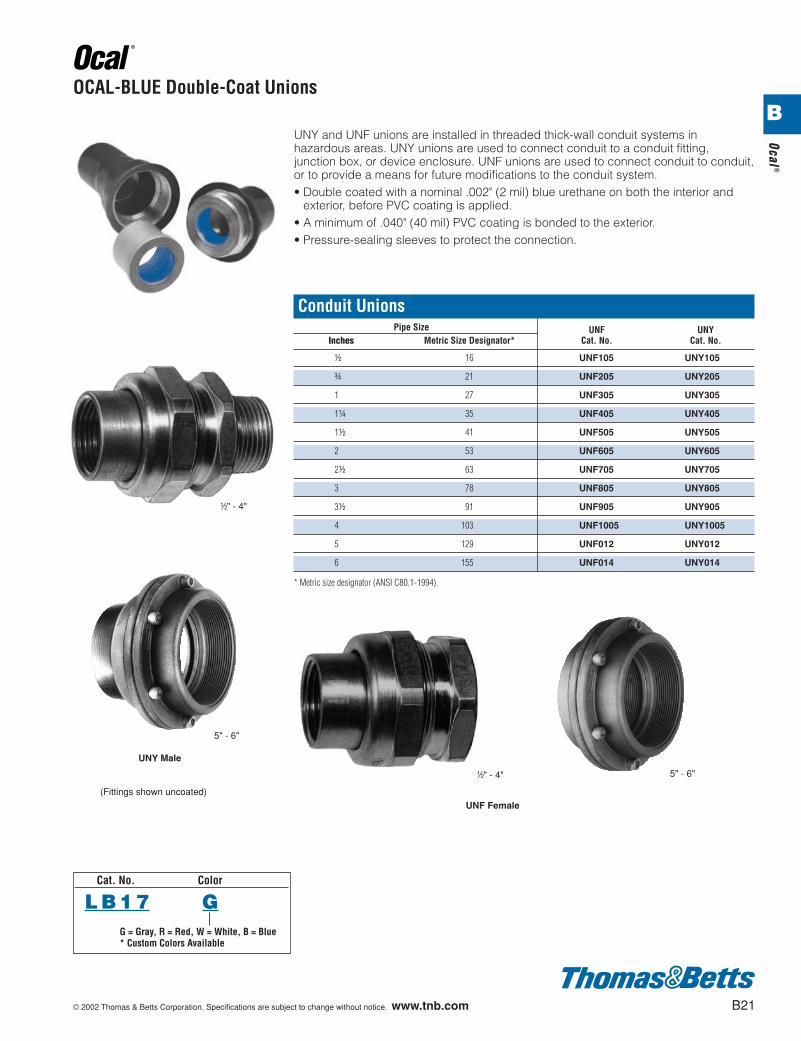
OCAL-BLUE Double-Coat Unions
UNY and UNF unions are installed in threaded thick-wall conduit systems inhazardous areas. UNY unions are used to connect conduit to a conduit fitting,junction box, or device enclosure. UNF unions are used to connect conduit to conduit,or to provide a means for future modifications to the conduit system.• Double coated with a nominal .002" (2 mil) blue urethane on both the interior and
exterior, before PVC coating is applied.• A minimum of .040" (40 mil) PVC coating is bonded to the exterior.• Pressure-sealing sleeves to protect the connection.
Conduit UnionsPipe Size UNF UNY
Inches Metric Size Designator* Cat. No. Cat. No.
d 16 UNF105 UNY105
f 21 UNF205 UNY205
1 27 UNF305 UNY305
1b 35 UNF405 UNY405
1d 41 UNF505 UNY505
2 53 UNF605 UNY605
2d 63 UNF705 UNY705
3 78 UNF805 UNY805
3d 91 UNF905 UNY905
4 103 UNF1005 UNY1005
5 129 UNF012 UNY012
6 155 UNF014 UNY014
* Metric size designator (ANSI C80.1-1994).
UNY Male
d" - 4"
5" - 6"
UNF Female
d" - 4" 5" - 6"
(Fittings shown uncoated)
Cat. No. Color
L B 1 7 GG = Gray, R = Red, W = White, B = Blue* Custom Colors Available
B
412031.B01 OCAL 3/5 3/13/03 5:02 PM Page 21
B22 © 2002 Thomas & Betts Corporation. Specifications are subject to change without notice. www.tnb.com
Ocal
®
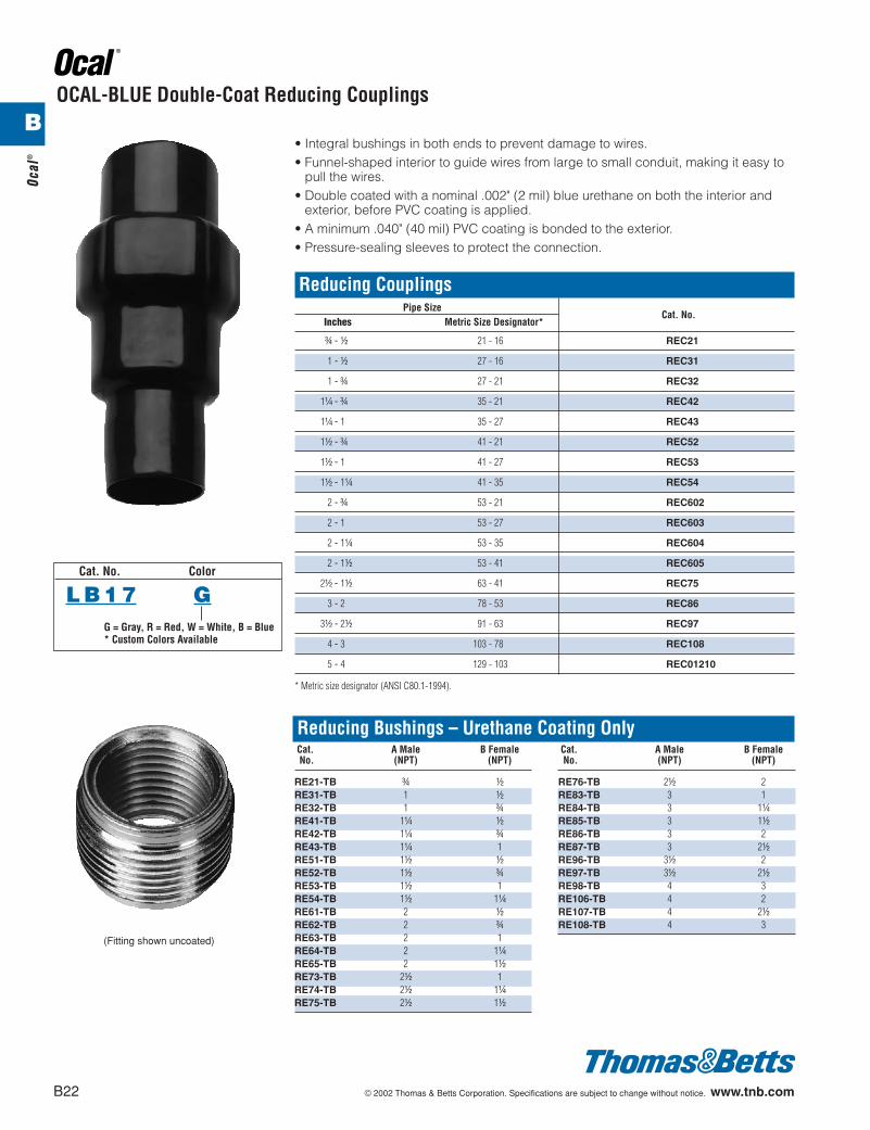
OCAL-BLUE Double-Coat Reducing Couplings
• Integral bushings in both ends to prevent damage to wires.• Funnel-shaped interior to guide wires from large to small conduit, making it easy to
pull the wires.• Double coated with a nominal .002" (2 mil) blue urethane on both the interior and
exterior, before PVC coating is applied.• A minimum .040" (40 mil) PVC coating is bonded to the exterior.• Pressure-sealing sleeves to protect the connection.
Reducing CouplingsPipe Size
Cat. No.Inches Metric Size Designator*
f - d 21 - 16 REC21
1 - d 27 - 16 REC31
1 - f 27 - 21 REC32
1b - f 35 - 21 REC42
1b - 1 35 - 27 REC43
1d - f 41 - 21 REC52
1d - 1 41 - 27 REC53
1d - 1b 41 - 35 REC54
2 - f 53 - 21 REC602
2 - 1 53 - 27 REC603
2 - 1b 53 - 35 REC604
2 - 1d 53 - 41 REC605
2d - 1d 63 - 41 REC75
3 - 2 78 - 53 REC86
3d - 2d 91 - 63 REC97
4 - 3 103 - 78 REC108
5 - 4 129 - 103 REC01210
* Metric size designator (ANSI C80.1-1994).
Reducing Bushings – Urethane Coating OnlyCat. A Male B FemaleNo. (NPT) (NPT)
RE21-TB f dRE31-TB 1 dRE32-TB 1 fRE41-TB 1b dRE42-TB 1b fRE43-TB 1b 1RE51-TB 1d dRE52-TB 1d fRE53-TB 1d 1RE54-TB 1d 1bRE61-TB 2 dRE62-TB 2 fRE63-TB 2 1RE64-TB 2 1bRE65-TB 2 1dRE73-TB 2d 1RE74-TB 2d 1bRE75-TB 2d 1d
Cat. A Male B FemaleNo. (NPT) (NPT)
RE76-TB 2d 2RE83-TB 3 1RE84-TB 3 1bRE85-TB 3 1dRE86-TB 3 2RE87-TB 3 2dRE96-TB 3d 2RE97-TB 3d 2dRE98-TB 4 3RE106-TB 4 2RE107-TB 4 2dRE108-TB 4 3
(Fitting shown uncoated)
Cat. No. Color
L B 1 7 GG = Gray, R = Red, W = White, B = Blue* Custom Colors Available
B
412031.B01 OCAL 3/5 3/13/03 5:02 PM Page 22

© 2002 Thomas & Betts Corporation. Specifications are subject to change without notice. www.tnb.com B23
Ocal®
Star® Teck Extreme™
To specify other material, add the appropriate suffix to the category number.
Desired Material Suffix ExampleAluminum fitting with ground lock nut GR STE-050GRSteel with zinc plate S STE-050SBrass with nickle plate BN STE-050BNAluminum with-pvc coating PVC STE-050PVCSteel with pvc coating S-PVC STE-050S-PVCStainless steel SS STE-050SS
Hub Strip Gland Range Over Jacket Range Over Armor A1: Throat A2: Throat B* CCat. Size Length Torque Dia. Min. Dia. Min. Overall Max. No. a.p.† (lb.-In.) Min. Max. Min. Max. w/End Stop wo/End Stop Alum.
Ordinary
ST050-462* d 1b 300 .525 .650 .415 .570 N/A* .395 2.020 1.224STE050* d 1b 300 .600 .985 .520 .895 .505 .612 2.650 1.630STE075* f 1b 600 .860 1.205 .780 1.125 .655 .816 2.900 2.080STE100* 1 1b 700 .950 1.375 .870 1.295 .785 1.044 3.020 2.300STE125* 1b 1b 1000 1.150 1.625 .990 1.465 .970 1.250 4.010 2.820STE150* 1d 1f 1200 1.440 1.965 1.280 1.805 1.260 1.562 4.290 3.250STE200* 2 1f 1600 1.825 2.375 1.665 2.215 1.645 1.995 4.120 3.600STE250 2d 2d 1600 2.865 2.810 2.105 2.680 2.075 2.424 5.320 4.750STE300 3 2d 1600 2.670 3.270 2.545 3.145 2.531 2.890 5.400 5.400STE350 3d 2d 1600 3.220 3.870 3.090 3.640 3.065 3.460 5.360 5.900STE400 4 2d 1600 3.665 4.340 3.550 4.225 3.525 3.941 5.415 6.400
Hazardous LocationsSTX050-462* d 1b 300 .525 .650 .415 .570 N/A* .395 2.500 1.630STX050-464* d 1b 300 .600 .760 .490 .680 N/A* .485 2.530 1.630STEX075* f 1b 600 .600 .985 .520 .895 .504 .678 3.400 1.820STEX100* 1 1b 700 .860 1.205 .780 1.125 .650 .833 3.580 2.300STEX125* 1b 1b 1000 .950 1.375 .870 1.295 .834 1.065 3.920 2.510STEX150* 1d 1f 1200 1.150 1.625 .990 1.465 .958 1.273 5.020 3.260STEX200* 2 1f 1600 1.440 1.965 1.280 1.805 1.250 1.560 5.120 3.620STEX250 2d 2d 1600 1.825 2.375 1.665 2.215 1.640 1.995 5.170 4.580STEX300 3 2d 1600 2.265 2.840 2.105 2.680 2.075 2.461 6.610 5.100STEX350 3d 2d 1600 2.670 3.270 2.545 3.145 2.531 2.864 7.380 5.790STEX400 4 2d 1600 3.220 3.870 3.090 3.640 3.055 3.461 7.650 6.190STEX400-484 4 – 1600 3.810 4.030 3.680 3.870 – – – –STEX400-485 4 – 1600 3.965 4.185 3.835 4.025 – – – –
¤
®
Collar Ring(elastomeric)
Bushing(elastomeric)
Gland Nut(aluminum)
Grounding Ring(stainless steel orbronze with nickel plate)
Body(aluminum)
Sealing Ring(elastomeric)
RemovableArmor-Stop(nylon d"-1")(aluminum 1b"-4")
C
B
A1
A2
STE SeriesOrdinary
STEX SeriesHazardous Locations
UL Listed #84H3* These products are UL ListedWatertight NEMA Type 6P.*The d fittings do not have a removable armor stop.
Sealing Compounds – Used for Hazardous LocationsCat. No. Description Volume
SC4-KIT Liquid type sealing compound for use in control cable applications 2.8 fl. oz.SC65 Putty Type Sealing Compound 60 grams
*
(Fittings shown uncoated)
Cat. No. Color
L B 1 7 GG = Gray, R = Red, W = White, B = Blue* Custom Colors Available
B
412031.B01 OCAL 3/5 3/13/03 5:02 PM Page 23
B24 © 2002 Thomas & Betts Corporation. Specifications are subject to change without notice. www.tnb.com
Ocal
®
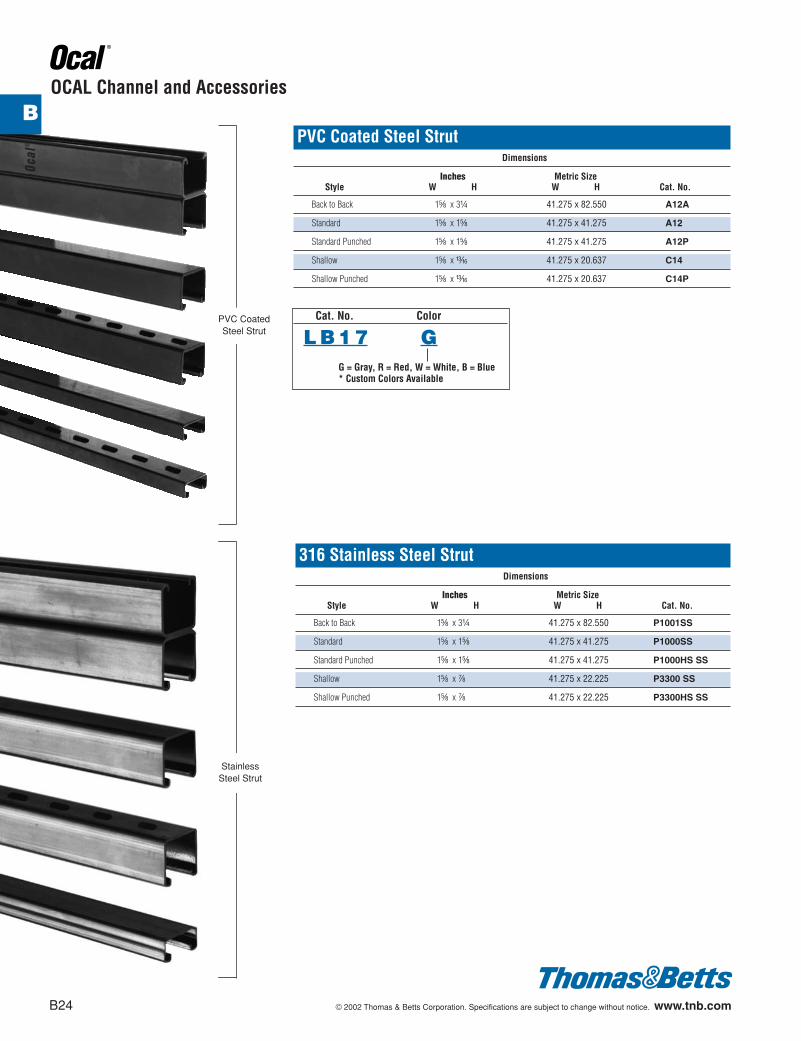
OCAL Channel and Accessories
PVC Coated Steel Strut Dimensions
Inches Metric SizeStyle W H W H Cat. No.
Back to Back 1e x 3b 41.275 x 82.550 A12A
Standard 1e x 1e 41.275 x 41.275 A12
Standard Punched 1e x 1e 41.275 x 41.275 A12P
Shallow 1e x m 41.275 x 20.637 C14
Shallow Punched 1e x m 41.275 x 20.637 C14P
316 Stainless Steel StrutDimensions
Inches Metric SizeStyle W H W H Cat. No.
Back to Back 1e x 3b 41.275 x 82.550 P1001SS
Standard 1e x 1e 41.275 x 41.275 P1000SS
Standard Punched 1e x 1e 41.275 x 41.275 P1000HS SS
Shallow 1e x g 41.275 x 22.225 P3300 SS
Shallow Punched 1e x g 41.275 x 22.225 P3300HS SS
PVC CoatedSteel Strut
Cat. No. Color
L B 1 7 GG = Gray, R = Red, W = White, B = Blue* Custom Colors Available
B
StainlessSteel Strut
412031.B01 OCAL 3/5 3/13/03 5:02 PM Page 24
© 2002 Thomas & Betts Corporation. Specifications are subject to change without notice. www.tnb.com B25
Ocal®
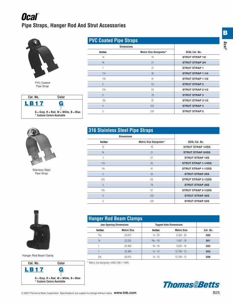
Pipe Straps, Hanger Rod And Strut Accessories
Stainless SteelPipe Strap
Hanger Rod Beam Clamp
PVC Coated Pipe StrapsDimensions
Inches Metric Size Designator* OCAL Cat. No.
d 16 STRUT STRAP 1/2
f 21 STRUT STRAP 3/4
1 27 STRUT STRAP 1
1b 35 STRUT STRAP 1-1/4
1d 41 STRUT STRAP 1-1/2
2 53 STRUT STRAP 2
2d 63 STRUT STRAP 2-1/2
3 78 STRUT STRAP 3
3d 91 STRUT STRAP 3-1/2
4 103 STRUT STRAP 4
5 129 STRUT STRAP 5
Hanger Rod Beam ClampsJaw Opening Dimensions Tapped Hole Dimensions
Inches Metric Size Inches Metric Size Cat. No.
n 23.812 b - 20 6.350 - 20 500
g 22.225 n - 18 7.937 - 18 501
1 25.400 c - 16 9.525 - 16 502
1 25.400 d - 13 12.700 - 13 503
2a 53.975 d - 13 12.700 - 13 508
* Metric size designator (ANSI C80.1-1994).
PVC CoatedPipe Strap
316 Stainless Steel Pipe StrapsDimensions
Inches Metric Size Designator* OCAL Cat. No.
d 16 STRUT STRAP 1/2SS
f 21 STRUT STRAP 3/4SS
1 27 STRUT STRAP 1SS
1b 35 STRUT STRAP 1-1/4SS
1d 41 STRUT STRAP 1-1/2SS
2 53 STRUT STRAP 2SS
2d 63 STRUT STRAP 2-1/2SS
3 78 STRUT STRAP 3SS
3d 91 STRUT STRAP 3-1/2SS
4 103 STRUT STRAP 4SS
5 129 STRUT STRAP 5SS
Cat. No. Color
L B 1 7 GG = Gray, R = Red, W = White, B = Blue* Custom Colors Available
Cat. No. Color
L B 1 7 GG = Gray, R = Red, W = White, B = Blue* Custom Colors Available
B
412031.B01 OCAL 3/5 3/13/03 5:02 PM Page 25
B26 © 2002 Thomas & Betts Corporation. Specifications are subject to change without notice. www.tnb.com
Ocal
®
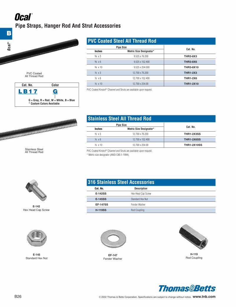
Pipe Straps, Hanger Rod And Strut Accessories
PVC Coated Steel All Thread RodPipe Size
Cat. No.Inches Metric Size Designator*
c x 3 9.525 x 76.200 THR3-8X3
c x 6 9.525 x 152.400 THR3-8X6
c x 10 9.525 x 254.000 THR3-8X10
d x 3 12.700 x 76.200 THR1-2X3
d x 6 12.700 x 152.400 THR1-2X6
d x 10 12.700 x 254.00 THR1-2X10
PVC Coated Kindorf® Channel and Struts are available upon request.
PVC CoatedAll Thread Rod
Stainless Steel All Thread RodPipe Size
Cat. No.Inches Metric Size Designator*
d x 3 12.700 x 76.200 THR1-2X3SS
d x 6 12.700 x 152.400 THR1-2X6SS
d x 10 12.700 x 254.00 THR1-2X10SS
PVC Coated Kindorf® Channel and Struts are available upon request.* Metric size designator (ANSI C80.1-1994).
Stainless SteelAll Thread Rod
316 Stainless Steel AccessoriesCat. No. Description
E-142SS Hex Head Cap Screw
E-145SS Standard Hex Nut
EF-147SS Fender Washer
H-119SS Rod Coupling
E-145Standard Hex Nut
EF-147Fender Washer
E-142Hex Head Cap Screw
H-119Rod Coupling
Cat. No. Color
L B 1 7 GG = Gray, R = Red, W = White, B = Blue* Custom Colors Available
B
412031.B01 OCAL 3/5 3/13/03 5:02 PM Page 26
© 2002 Thomas & Betts Corporation. Specifications are subject to change without notice. www.tnb.com B27
Ocal®
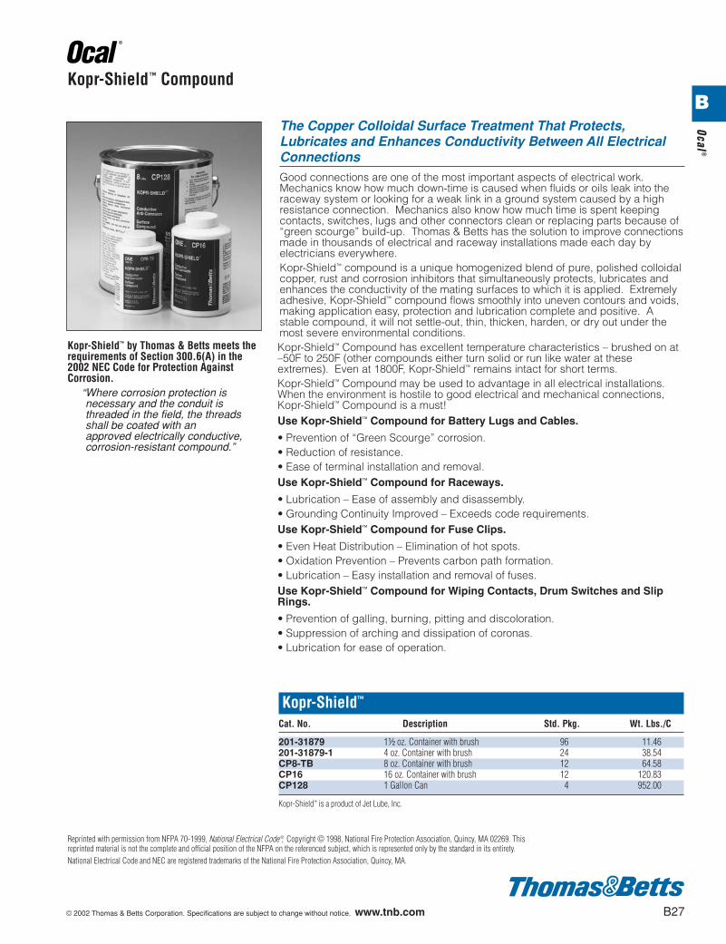
Kopr-Shield™ Compound
The Copper Colloidal Surface Treatment That Protects,Lubricates and Enhances Conductivity Between All ElectricalConnectionsGood connections are one of the most important aspects of electrical work.Mechanics know how much down-time is caused when fluids or oils leak into theraceway system or looking for a weak link in a ground system caused by a highresistance connection. Mechanics also know how much time is spent keepingcontacts, switches, lugs and other connectors clean or replacing parts because of“green scourge” build-up. Thomas & Betts has the solution to improve connectionsmade in thousands of electrical and raceway installations made each day byelectricians everywhere.Kopr-Shield™ compound is a unique homogenized blend of pure, polished colloidalcopper, rust and corrosion inhibitors that simultaneously protects, lubricates andenhances the conductivity of the mating surfaces to which it is applied. Extremelyadhesive, Kopr-Shield™ compound flows smoothly into uneven contours and voids,making application easy, protection and lubrication complete and positive. Astable compound, it will not settle-out, thin, thicken, harden, or dry out under themost severe environmental conditions.Kopr-Shield™ Compound has excellent temperature characteristics – brushed on at–50F to 250F (other compounds either turn solid or run like water at theseextremes). Even at 1800F, Kopr-Shield™ remains intact for short terms.Kopr-Shield™ Compound may be used to advantage in all electrical installations.When the environment is hostile to good electrical and mechanical connections,Kopr-Shield™ Compound is a must!Use Kopr-Shield™ Compound for Battery Lugs and Cables.
• Prevention of “Green Scourge” corrosion.• Reduction of resistance.• Ease of terminal installation and removal.Use Kopr-Shield™ Compound for Raceways.
• Lubrication – Ease of assembly and disassembly.• Grounding Continuity Improved – Exceeds code requirements.Use Kopr-Shield™ Compound for Fuse Clips.
• Even Heat Distribution – Elimination of hot spots.• Oxidation Prevention – Prevents carbon path formation.• Lubrication – Easy installation and removal of fuses.Use Kopr-Shield™ Compound for Wiping Contacts, Drum Switches and SlipRings.
• Prevention of galling, burning, pitting and discoloration.• Suppression of arching and dissipation of coronas.• Lubrication for ease of operation.
Kopr-Shield™
Cat. No. Description Std. Pkg. Wt. Lbs./C
201-31879 1d oz. Container with brush 96 11.46201-31879-1 4 oz. Container with brush 24 38.54CP8-TB 8 oz. Container with brush 12 64.58CP16 16 oz. Container with brush 12 120.83CP128 1 Gallon Can 4 952.00
Kopr-Shield™ is a product of Jet Lube, Inc.
Kopr-Shield™ by Thomas & Betts meets therequirements of Section 300.6(A) in the2002 NEC Code for Protection AgainstCorrosion.
“Where corrosion protection isnecessary and the conduit isthreaded in the field, the threadsshall be coated with anapproved electrically conductive,corrosion-resistant compound.”
Reprinted with permission from NFPA 70-1999, National Electrical Code ®, Copyright © 1998, National Fire Protection Association, Quincy, MA 02269. Thisreprinted material is not the complete and official position of the NFPA on the referenced subject, which is represented only by the standard in its entirety.National Electrical Code and NEC are registered trademarks of the National Fire Protection Association, Quincy, MA.
B
412031.B01 OCAL 3/5 3/13/03 5:02 PM Page 27
B28 © 2002 Thomas & Betts Corporation. Specifications are subject to change without notice. www.tnb.com
Ocal
®
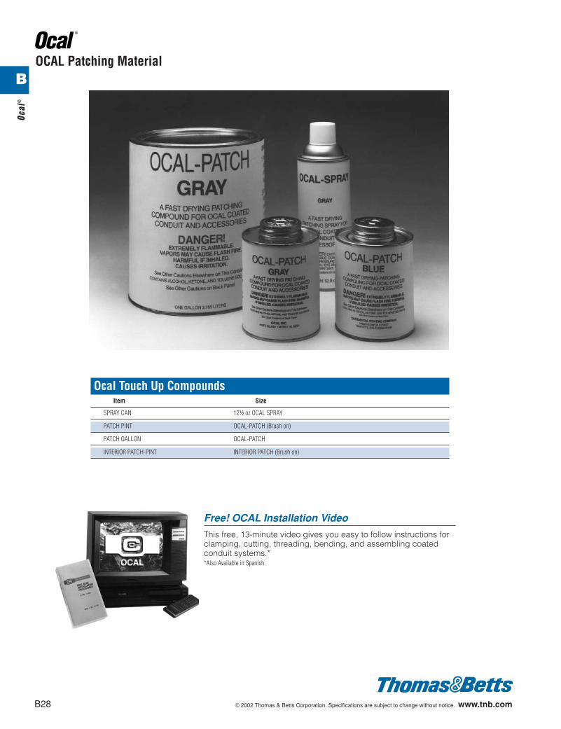
OCAL Patching Material
Ocal Touch Up CompoundsItem Size
SPRAY CAN 12d oz OCAL SPRAY
PATCH PINT OCAL-PATCH (Brush on)
PATCH GALLON OCAL-PATCH
INTERIOR PATCH-PINT INTERIOR PATCH (Brush on)
Free! OCAL Installation Video
This free, 13-minute video gives you easy to follow instructions forclamping, cutting, threading, bending, and assembling coatedconduit systems.**Also Available in Spanish.
B
412031.B01 OCAL 3/5 3/13/03 5:02 PM Page 28
© 2002 Thomas & Betts Corporation. Specifications are subject to change without notice. www.tnb.com B29
Ocal®
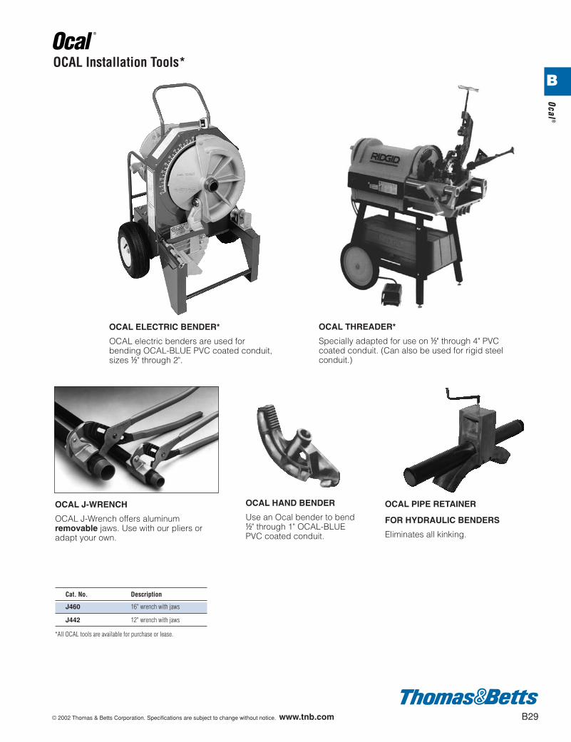
OCAL Installation Tools*
Cat. No. Description
J460 16" wrench with jaws
J442 12" wrench with jaws
*All OCAL tools are available for purchase or lease.
OCAL ELECTRIC BENDER*
OCAL electric benders are used forbending OCAL-BLUE PVC coated conduit,sizes d" through 2".
OCAL J-WRENCH
OCAL J-Wrench offers aluminumremovable jaws. Use with our pliers oradapt your own.
OCAL HAND BENDER
Use an Ocal bender to bendd" through 1" OCAL-BLUEPVC coated conduit.
OCAL PIPE RETAINER
FOR HYDRAULIC BENDERS
Eliminates all kinking.
OCAL THREADER*
Specially adapted for use on d" through 4" PVCcoated conduit. (Can also be used for rigid steelconduit.)
B
412031.B01 OCAL 3/5 3/13/03 5:02 PM Page 29
B30 © 2002 Thomas & Betts Corporation. Specifications are subject to change without notice. www.tnb.com
Ocal
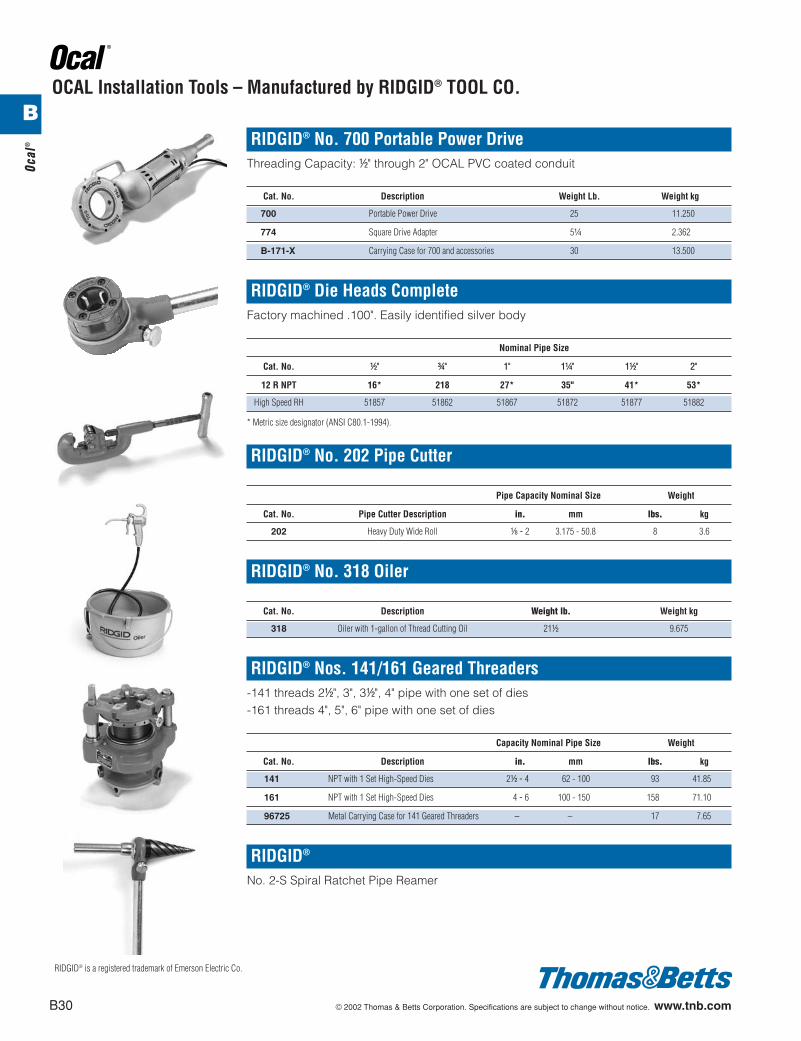
® RIDGID® No. 700 Portable Power DriveThreading Capacity: d" through 2" OCAL PVC coated conduit
Cat. No. Description Weight Lb. Weight kg
700 Portable Power Drive 25 11.250
774 Square Drive Adapter 5b 2.362
B-171-X Carrying Case for 700 and accessories 30 13.500
RIDGID® Die Heads CompleteFactory machined .100". Easily identified silver body
Nominal Pipe Size
Cat. No. d" f" 1" 1b" 1d" 2"
12 R NPT 16* 218 27* 35" 41* 53*
High Speed RH 51857 51862 51867 51872 51877 51882
* Metric size designator (ANSI C80.1-1994).
RIDGID® No. 202 Pipe Cutter
Pipe Capacity Nominal Size Weight
Cat. No. Pipe Cutter Description in. mm lbs. kg
202 Heavy Duty Wide Roll a - 2 3.175 - 50.8 8 3.6
RIDGID® No. 318 Oiler
Cat. No. Description Weight lb. Weight kg
318 Oiler with 1-gallon of Thread Cutting Oil 21d 9.675
RIDGID® Nos. 141/161 Geared Threaders-141 threads 2d", 3", 3d", 4" pipe with one set of dies-161 threads 4", 5", 6" pipe with one set of dies
Capacity Nominal Pipe Size Weight
Cat. No. Description in. mm lbs. kg
141 NPT with 1 Set High-Speed Dies 2d - 4 62 - 100 93 41.85
161 NPT with 1 Set High-Speed Dies 4 - 6 100 - 150 158 71.10
96725 Metal Carrying Case for 141 Geared Threaders – – 17 7.65
RIDGID®
No. 2-S Spiral Ratchet Pipe Reamer
RIDGID® is a registered trademark of Emerson Electric Co.
OCAL Installation Tools – Manufactured by RIDGID® TOOL CO.B
412031.B01 OCAL 3/5 3/13/03 5:02 PM Page 30
© 2002 Thomas & Betts Corporation. Specifications are subject to change without notice. www.tnb.com B31
Ocal®
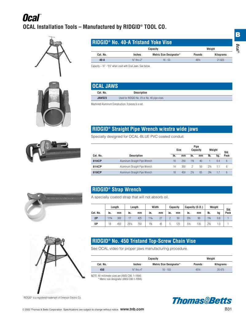
RIDGID® No. 40-A Tristand Yoke ViseCapacity Weight
Cat. No. Inches Metric Size Designator* Pounds Kilograms
40-A d" thru 2" 16 - 53 48d 21.825
Capacity – d" - 1d" when used with Ocal Jaws. See below.
OCAL JAWSCat. No. Description
JAWS23 Used for RIDGID No. 23 or No. 40 pipe vises.
Machined Aluminum Construction. 3 pieces to a set.
RIDGID® Straight Pipe Wrench w/extra wide jawsSpecially designed for OCAL-BLUE PVC coated conduit.
PipeSize Capacity Weight
Std.Cat. No. Description in. mm in. mm lb. kg. Pack
810CP Aluminum Straight Pipe Wrench 10 250 1d 40 1 0.4 6
814CP Aluminum Straight Pipe Wrench 14 350 2 50 2d 1.1 6
818CP Aluminum Straight Pipe Wrench 18 450 2d 65 3f 1.7 6
RIDGID® Strap WrenchA specially coated strap that will not absorb oil.
Length Length Width Capacity Capacity (O.D.) WeightStd.
Cat. No. in. mm in. mm in. mm in. mm in. mm lb. kg Pack
2P 11f 300 17 425 1h 27 2 50 3d 90 1f 0.8 1
5P 18 450 29b 750 1f 45 5 125 5d 135 2f 1.0 1
RIDGID® No. 450 Tristand Top-Screw Chain ViseSee OCAL video for proper jaws manufacturing procedure.
Capacity Weight
Cat. No. Inches Metric Size Designator* Pounds Kilograms
450 d" thru 4" 16 - 103 45d 20.475
NOTE: All millimeter sizes are (ANSI C80. 1-1994)* Metric size designator (ANSI C80.1-1994).
RIDGID® is a registered trademark of Emerson Electric Co.
OCAL Installation Tools – Manufactured by RIDGID® TOOL CO.B
412031.B01 OCAL 3/5 3/13/03 5:02 PM Page 31
B32 © 2002 Thomas & Betts Corporation. Specifications are subject to change without notice. www.tnb.com
Ocal
®
BSolutions Conc. Temp. Recommended
ExposureSplashing Liquid Fumes
Solutions Conc. Temp. RecommendedExposure
Splashing Liquid Fumes
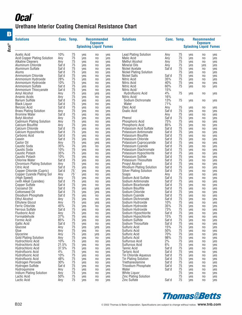
Acetic Acid 10% 75 yes no yesAcid Copper Plating Solution Any 75 yes no yesAlkaline Cleaners Any 75 yes no yesAluminum Chloride Sat'd 75 yes no yesAluminum Sulfate Sat'd 75 yes no yesAlums Sat'd 75 yes no yesAmmonium Chloride Sat'd 75 yes no yesAmmonium Hydroxide 28% 75 yes no yesAmmonium Hydroxide 10% 75 yes no yesAmmonium Sulfate Sat'd 75 yes no yesAmmonium Thiocyanate Sat'd 75 yes no yesAmyl Alcohol Any 75 yes yes yesArsenic Acids Any 75 yes no yesBarium Sulfide Sat'd 75 yes no yesBlack Liquor Sat'd 75 yes no yesBenzoic Acid Sat'd 75 yes no yesBrass Plating Solution Any 75 yes no yesBromine Water Sat'd 75 yes no yesButyl Alcohol Any 75 yes no yesCadmium Plating Solution Any 75 yes no yesCalcium Bisulfite Any 75 yes no yesCalcium Chloride Sat'd 75 yes no yesCalcium Hypochlorite Sat'd 75 yes no yesCarbonic Acid Sat'd 75 yes no yesCasein Sat'd 75 yes no yesCastor Oil Any 75 yes yes yesCaustic Soda 35% 75 yes no yesCaustic Soda 10% 75 yes no yesCaustic Potash 35% 75 yes no yesCaustic Potash 10% 75 yes no yesChlorine Water Sat'd 75 yes no yesChromium Plating Solution Any 75 yes no yesCitric Acid Sat'd 75 yes no yesCopper Chloride (Cupric) Sat'd 75` yes no yesCopper Cyanide Plating Sol Any 75` yes no yes(High Speed) Any 75 yes no yes(with Alkali Cyanides) Sat'd 75 yes no yesCopper Sulfate Sat'd 75 yes no yesCocoanut Oil Sat'd 75 yes yes yesCottonseed Oil Sat'd 75 yes yes yesDisodium Phosphate Sat'd 75 yes no yesEthyl Alcohol Any 75 yes no yesEthylene Glycol Any 75 yes yes yesFerric Chloride 45% 75 yes no yesFerrous Sulfate Sat'd 75 yes no yesFluoboric Acid Any 75 yes no yesFormaldehyde 37% 75 yes no yesFormic Acid 85% 75 yes no yesGallic Acid Sat'd 75 yes no yesGlucose Any 75 yes yes yesGlue Any 75 yes no yesGlycerine Any 75 yes yes yesGold Plating Solution Any 75 yes no yesHydrochloric Acid 10% 75 yes no yesHydrochloric Acid 21.5% 75 yes no yesHydrochloric Acid 37.5% 75 yes no yesHydrofluoric Acid 4% 75 yes no yesHydrofluoric Acid 10% 75 yes no yesHydrofluoric Acid 48% 75 yes no yesHydrogen Peroxide 30% 75 yes no yesHydrogen Sulfide Sat'd 75 yes no yesHydroquinone Any 75 yes no yesIndium Plating Solution Any 75 yes no yesLactic Acid 50% 75 yes no yesLactic Acid Any 75 yes no yes
Lead Plating Solution Any 75 yes no yesMalic Acid Any 75 yes no yesMethyl Alcohol Any 75 yes no yesMineral Oils Any 75 yes yes yesNickel Acetate Sat'd 75 yes no yesNickel Plating Solution 75 yes no yesNickel Salts Sat'd 75 yes no yesNitric Acid 35% 75 yes no yesNitric Acid 40% 75 yes no yesNitric Acid 60% 75 yes no yesNitric Acid/ 15%Hydrofluoric Acid 4% 75 yes no yes
Nitric Acid/ 16%Sodium Dichromate 13% 75 yes no yesWater 71%
Oleic Acid Any 75 yes no yesOxalic Acid Sat'd 75 yes no yes
Any 75 yes no yesPhenol Sat'd 75 yes no yesPhosphoric Acid 75% 75 yes no yesPhosphoric Acid 85% 75 yes no yesPotassium Acid Sulfate Sat'd 75 yes no yesPotassium Antimonate Sat'd 75 yes no yesPotassium Bisulfite Sat'd 75 yes no yesPotassium Chloride Sat'd 75 yes no yesPotassium Cuprocyanide Sat'd 75 yes no yesPotassium Cyanide Sat'd 75 yes no yesPotassium Diachromate Sat'd 75 yes no yesPotassium Hypochlorite Sat'd 75 yes no yesPotassium Sulfide Sat'd 75 yes no yesPotassium Thiosulfate Sat'd 75 yes no yesPropyl Alcohol Sat'd 75 yes no yesRhodium Plating Solution Sat'd 75 yes no yesSilver Plating Solution Sat'd 75 yes no yesSoaps Any 75 yes no yesSodium Acid Sulfate Sat'd 75 yes no yesSodium Antimonate Sat'd' 75 yes no yesSodium Bicarbonate Sat'd 75 yes no yesSodium Bisulfite Sat'd 75 yes no yesSodium Chloride Sat'd 75 yes no yesSodium Cyanide Sat'd 75 yes no yesSodium Dichromate Sat'd 75 yes no yesSodium Hydroxide 10% 75 yes no yesSodium Hydroxide 35% 75 yes no yesSodium Hydroxide 73% 75 yes no yesSodium Hypochlorite Sat'd 75 yes no yesSodium Hypochlorite 15% 75 yes no yesSodium Sulfide Sat'd 75 yes no yesSodium Thiosulfate Sat'd 75 yes no yesSulfuric Acid 15% 75 yes no yesSulfuric Acid 50% 75 yes no yesSulfuric Acid 70% 75 yes no yesSulfuric Acid 98% 75 yes no yesSulfurous Acid 2% 75 yes no yesSulfurous Acid 6% 75 yes no yesTannic Acid Sat'd 75 yes no yesTartaric Acid Sat'd 75 yes no yesTin Chloride Aqueous Sat'd 75 yes no yesTin Plating Solution Sat'd 75 yes no yesTriethaneolamine Sat'd 75 yes no yesTrisodium Phosphate Sat’d 75 yes no yesWater Sat'd 75 yes no yesWhite Liquor 75 yes no yesZinc Plating Solution 75 yes no yesZinc Sulfate Sat'd 75 yes no yes
Urethane Interior Coating Chemical Resistance Chart
412031.B01 OCAL 3/5 3/13/03 5:02 PM Page 32

© 2002 Thomas & Betts Corporation. Specifications are subject to change without notice. www.tnb.com B33
Ocal®
BPVC Coating Chemical Resistance Chart
Solutions Conc. Temp. RecommendedExposure
Splashing Liquid Fumes
Solutions Conc. Temp. RecommendedExposure
Splashing Liquid Fumes
Acetic Acid 10% 120 no no noAcid Copper Plating Solution 160 yes yes yesAlkaline Cleaners 160 yes yes yesAluminum Chloride Sat'd 160 yes yes yesAluminum Sulfate Sat'd 160 yes yes yesAlums Sat'd 160 yes yes yesAmmonium Chloride Sat'd 160 yes yes yesAmmonium Hydroxide 28% 120 yes yes yesAmmonium Hydroxide 10% 120 yes yes yesAmmonium Sulfate Sat'd 160 yes yes yesAmmonium Thiocyanate Sat'd 160 yes yes yesAmyl Alcohol Any 90 yes yes yesArsenic Acids Any 150 yes yes yesBarium Sulfide Sat'd 120 yes yes yesBlack Liquor Sat'd 90 yes yes yesBenzoic Acid Sat'd 160 yes yes yesBrass Plating Solution Any 160 yes yes yesBromine Water Sat'd 120 yes yes yesButyl Alcohol Any 90 yes yes yesCadmium Plating Solution Any 150 yes yes yesCalcium Bisulfite Any 150 yes yes yesCalcium Chloride Sat'd 160 yes yes yesCalcium Hypochlorite Sat'd 120 yes yes yesCarbonic Acid Sat'd 160 yes yes yesCasein Sat'd 90 yes yes yesCastor Oil Any 90 yes yes yesCaustic Soda 35% 120 yes yes yesCaustic Soda 10% 150 yes yes yesCaustic Potash 35% 120 yes yes yesCaustic Potash 10% 150 yes yes yesChlorine Water Sat'd 90 yes yes yesChromium Plating Solution Any 150 yes yes yesCitric Acid Sat'd 160 yes yes yesCopper Chloride (Cupric) Sat'd 160 yes yes yesCopper Cyanide Plating Sol Any 160 yes yes yes(High Speed) Any 180 yes yes yes(with Alkali Cyanides) Sat'd 160 yes yes yesCopper Sulfate Sat'd 160 yes yes yesCocoanut Oil Sat'd 90 yes yes yesCottonseed Oil Sat'd 90 yes yes yesDisodium Phosphate Sat'd 160 yes yes yesEthyl Alcohol Any 90 yes yes yesEthylene Glycol Any 90 yes no yesFerric Chloride 45% 120 yes yes yesFerrous Sulfate Sat'd 150 yes yes yesFluoboric Acid Any 150 yes yes yesFormaldehyde 37% 120 yes yes yesFormic Acid 85% 100 no no noGallic Acid Sat'd 150 no no yesGlucose Any 150 yes yes yesGlue Any 150 yes yes yesGlycerine Any 90 yes yes yesGold Plating Solution Any 150 yes yes yesHydrochloric Acid 10% 120 yes no yesHydrochloric Acid 21.5% 120 yes no yesHydrochloric Acid 37.5% 120 yes no yesHydrochloric Acid 37.5% 90 yes no yesHydrofluoric Acid 4% 140 yes no yesHydrofluoric Acid 10% 120 yes no yesHydrofluoric Acid 48% 120 yes no yesHydrogen Peroxide 30% 120 yes yes yesHydrogen Sulfide Sat'd 120 yes yes yesHydroquinone Any 90 yes yes yesIndium Plating Solution Any 150 yes yes yesLactic Acid 50% 120 yes yes yesLactic Acid Any 90 yes yes yesLead Plating Solution Any 150 yes yes yes
Malic Acid Any 90 yes yes yesMethyl Alcohol Any 90 yes yes yesMineral Oils Any 90 yes yes yesNickel Acetate Sat'd 160 yes yes yesNickel Plating Solution 160 yes yes yesNickel Salts Sat'd 160 yes yes yesNitric Acid 35% 120 yes no yesNitric Acid 40% 90 yes no yesNitric Acid 60% 120 yes no yesNitric Acid/ 15%Hydrofluoric Acid 4% 140 yes yes yes
Nitric Acid/ 16%Sodium Dichromate 13% 130 yes yes yesWater 71%
Oleic Acid Any 90 yes yes yesOxalic Acid Sat'd 120 yes yes yes
Any 90 yes yes yesPhenol Sat'd 120 no no noPhosphoric Acid 75% 150 yes yes yesPhosphoric Acid 85% 120 yes yes yesPhosphoric Acid 85% 160 yes yes yesPotassium Acid Sulfate Sat'd 150 yes yes yesPotassium Antimonate Sat'd 150 yes yes yesPotassium Bisulfite Sat'd 90 yes yes yesPotassium Chloride Sat'd 160 yes yes yesPotassium Cuprocyanide Sat'd 150 yes yes yesPotassium Cyanide Sat'd 160 yes yes yesPotassium Diachromate Sat'd 160 yes yes yesPotassium Hypochlorite Sat'd 90 yes no yesPotassium Sulfide Sat'd 150 yes yes yesPotassium Thiosulfate Sat'd 150 yes yes yesPropyl Alcohol Sat'd 150 yes yes yesRhodium Plating Solution Sat'd 150 yes yes yesSilver Plating Solution Sat'd 150 yes yes yesSoaps Any 90 yes yes yesSodium Acid Sulfate Sat'd 160 yes yes yesSodium Antimonate Sat'd' 150 yes yes yesSodium Bicarbonate Sat'd 160 yes yes yesSodium Bisulfite Sat'd 90 yes yes yesSodium Chloride Sat'd 160 yes yes yesSodium Cyanide Sat'd 160 yes yes yesSodium Dichromate Sat'd 160 yes yes yesSodium Hydroxide 10% 150 yes no yesSodium Hydroxide 35% 120 yes no yesSodium Hydroxide 73% 160 no no noSodium Hypochlorite Sat'd 90 yes no yesSodium Hypochlorite 15% 120 yes no yesSodium Sulfide Sat'd 150 yes yes yesSodium Thiosulfate Sat'd 150 yes yes yesSulfuric Acid 15% 120 yes yes yesSulfuric Acid 15% 160 yes yes yesSulfuric Acid 50% 120 yes yes yesSulfuric Acid 70% 90 yes no yesSulfuric Acid 98% 100 no no yesSulfurous Acid 2% 120 yes no yesSulfurous Acid 6% 120 yes no yesTannic Acid Sat'd 90 yes yes yesTartaric Acid Sat'd 90 yes yes yesTin Chloride Aqueous Sat'd 150 yes yes yesTin Plating Solution Sat'd 150 yes yes yesTriethaneolamine Sat'd 150 yes yes yesTrisodium Phosphate Sat’d 150 yes yes yesWater Sat'd 160 yes yes yesWhite Liquor 90 yes yes yesZinc Plating Solution 160 yes yes yesZinc Sulfate Sat'd 160 yes yes yes
412031.B01 OCAL 3/5 3/13/03 5:02 PM Page 33
B34 © 2002 Thomas & Betts Corporation. Specifications are subject to change without notice. www.tnb.com
Ocal
®
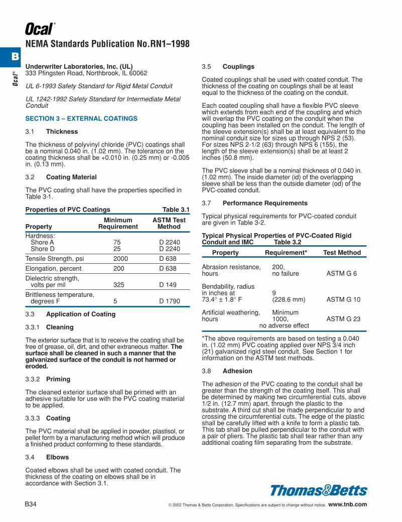
NEMA Standards Publication No.RN1–1998
Underwriter Laboratories, Inc. (UL)333 Pfingsten Road, Northbrook, IL 60062
UL 6-1993 Safety Standard for Rigid Metal Conduit
UL 1242-1992 Safety Standard for Intermediate MetalConduit
SECTION 3 – EXTERNAL COATINGS
3.1 Thickness
The thickness of polyvinyl chloride (PVC) coatings shallbe a nominal 0.040 in. (1.02 mm). The tolerance on thecoating thickness shall be +0.010 in. (0.25 mm) or -0.005in. (0.13 mm).
3.2 Coating Material
The PVC coating shall have the properties specified inTable 3-1.
Properties of PVC Coatings Table 3.1
Minimum ASTM TestProperty Requirement MethodHardness:
Shore A 75 D 2240Shore D 25 D 2240
Tensile Strength, psi 2000 D 638
Elongation, percent 200 D 638
Dielectric strength,volts per mil 325 D 149
Brittleness temperature,degrees F 5 D 1790
3.3 Application of Coating
3.3.1 Cleaning
The exterior surface that is to receive the coating shall befree of grease, oil, dirt, and other extraneous matter. Thesurface shall be cleaned in such a manner that the galvanized surface of the conduit is not harmed oreroded.
3.3.2 Priming
The cleaned exterior surface shall be primed with anadhesive suitable for use with the PVC coating materialto be applied.
3.3.3 Coating
The PVC material shall be applied in powder, plastisol, orpellet form by a manufacturing method which will producea finished product conforming to these standards.
3.4 Elbows
Coated elbows shall be used with coated conduit. Thethickness of the coating on elbows shall be inaccordance with Section 3.1.
3.5 Couplings
Coated couplings shall be used with coated conduit. Thethickness of the coating on couplings shall be at leastequal to the thickness of the coating on the conduit.
Each coated coupling shall have a flexible PVC sleevewhich extends from each end of the coupling and whichwill overlap the PVC coating on the conduit when thecoupling has been installed on the conduit. The length ofthe sleeve extension(s) shall be at least equivalent to thenominal conduit size for sizes up through NPS 2 (53).For sizes NPS 2-1/2 (63) through NPS 6 (155), thelength of the sleeve extension(s) shall be at least 2inches (50.8 mm).
The PVC sleeve shall be a nominal thickness of 0.040 in.(1.02 mm). The inside diameter (id) of the overlappingsleeve shall be less than the outside diameter (od) of thePVC-coated conduit.
3.7 Performance Requirements
Typical physical requirements for PVC-coated conduitare given in Table 3-2.
Typical Physical Properties of PVC-Coated RigidConduit and IMC Table 3.2
Property Requirement* Test Method
Abrasion resistance, 200,hours no failure ASTM G 6
Bendability, radiusin inches at 973.4° ± 1.8° F (228.6 mm) ASTM G 10
Artificial weathering, Minimumhours 1000, ASTM G 23
no adverse effect
*The above requirements are based on testing a 0.040in. (1.02 mm) PVC coating applied over NPS 3/4 inch(21) galvanized rigid steel conduit. See Section 1 forinformation on the ASTM test methods.
3.8 Adhesion
The adhesion of the PVC coating to the conduit shall begreater than the strength of the coating itself. This shallbe determined by making two circumferential cuts, above1/2 in. (12.7 mm) apart, through the plastic to thesubstrate. A third cut shall be made perpendicular to andcrossing the circumferential cuts. The edge of the plasticshall be carefully lifted with a knife to form a plastic tab.This tab shall be pulled perpendicular to the conduit witha pair of pliers. The plastic tab shall tear rather than anyadditional coating film separating from the substrate.
B
412031.B01 OCAL 3/5 3/13/03 5:02 PM Page 34
© 2002 Thomas & Betts Corporation. Specifications are subject to change without notice. www.tnb.com B35
Ocal®
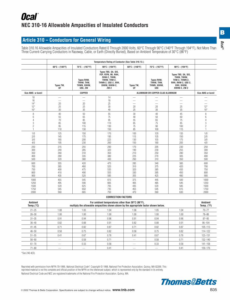
NEC 310-16 Allowable Ampacities of Insulated Conductors
Temperature Rating of Conductor (See Table 310.13.)
60°C – (140°F) 75°C – (167°F) 90°C – (194°F) 60°C – (140°F) 75°C – (167°F) 90°C – (194°F)
Types TBS, SA, SIS,FEP, FEPB, MI, RHH, Types TBS, SA, SIS,
RHW-2, THHN, THHN, THHW,Types RHW, THHW, THW-2, Types RHW, THW-2, THWN-2,THHW, THW, THWN-2, USE-2, XHH, THHW, THW, RHH, RHW-2, USE-2,
Types TW, THWN, XHHW, XHHW, XHHW-2, Types TW, THWN, XHHW, XHH, XHHW,UF USE, ZW ZW-2 UF USE XHHW-2, ZW-2
Size AWG or kcmil COPPER ALUMINUM OR COPPER-CLAD ALUMINUM Size AWG or kcmil
18 — — 14 — — — —16 — — 18 — — — —14* 20 20 25 — — — —12* 25 25 30 20 20 25 12*10* 30 35 40 25 30 35 10*
8 40 50 55 30 40 45 86 55 65 75 40 50 60 64 70 85 95 55 65 75 43 85 100 110 65 75 85 32 95 115 130 75 90 100 21 110 130 150 85 100 115 1
1/0 125 150 170 100 120 135 1/02/0 145 175 195 115 135 150 2/03/0 165 200 225 130 155 175 3/04/0 195 230 260 150 180 205 4/0
250 215 255 290 170 205 230 250300 240 285 320 190 230 255 300350 260 310 350 210 250 280 350400 280 335 380 225 270 305 400500 320 380 430 260 310 350 500
600 355 420 475 285 340 385 600700 385 460 520 310 375 420 700750 400 475 535 320 385 435 750800 410 490 555 330 395 450 800900 435 520 585 355 425 480 900
1000 455 545 615 375 445 500 10001250 495 590 665 405 485 545 12501500 520 625 705 435 520 585 15001750 545 650 735 455 545 615 17502000 560 665 750 470 560 630 2000
CORRECTION FACTORS
Ambient For ambient temperatures other than 30°C (86°F), AmbientTemp.(°C) multiply the allowable ampacities shown above by the appropriate factor shown below. Temp. (°F)
21–25 1.08 1.05 1.04 1.08 1.05 1.04 70–77
26–30 1.00 1.00 1.00 1.00 1.00 1.00 78–86
31–35 0.91 0.94 0.96 0.91 0.94 0.96 87–95
36–40 0.82 0.88 0.91 0.82 0.88 0.91 96–104
41–45 0.71 0.82 0.87 0.71 0.82 0.87 105–113
46–50 0.58 0.75 0.82 0.58 0.75 0.82 114–122
51–55 0.41 0.67 0.76 0.41 0.67 0.76 123–131
56–60 — 0.58 0.71 — 0.58 0.71 132–140
61–70 — 0.33 0.58 — 0.33 0.58 141–158
71–80 — — 0.41 — — 0.41 159–176
*See 240.4(D).
Article 310 – Conductors for General WiringTable 310.16 Allowable Ampacities of Insulated Conductors Rated 0 Through 2000 Volts, 60°C Through 90°C (140°F Through 194°F), Not More ThanThree Current-Carrying Conductors in Raceway, Cable, or Earth (Directly Buried), Based on Ambient Temperature of 30°C (86°F)
Reprinted with permission from NFPA 70-1999, National Electrical Code ®, Copyright © 1998, National Fire Protection Association, Quincy, MA 02269. Thisreprinted material is not the complete and official position of the NFPA on the referenced subject, which is represented only by the standard in its entirety.National Electrical Code and NEC are registered trademarks of the National Fire Protection Association, Quincy, MA.
B
412031.B01 OCAL 3/5 3/13/03 5:02 PM Page 35
B36 © 2002 Thomas & Betts Corporation. Specifications are subject to change without notice. www.tnb.com
Ocal
®
B
CONDUCTORS
Conductor Metric Designator (Trade Size)
Size 16 21 27 35 41 53 63 78 91 103 129 155Type (AWG/kcmil) (d) (f) (1) (1b) (1d) (2) (2d) (3) (3d) (4) (5) (6)
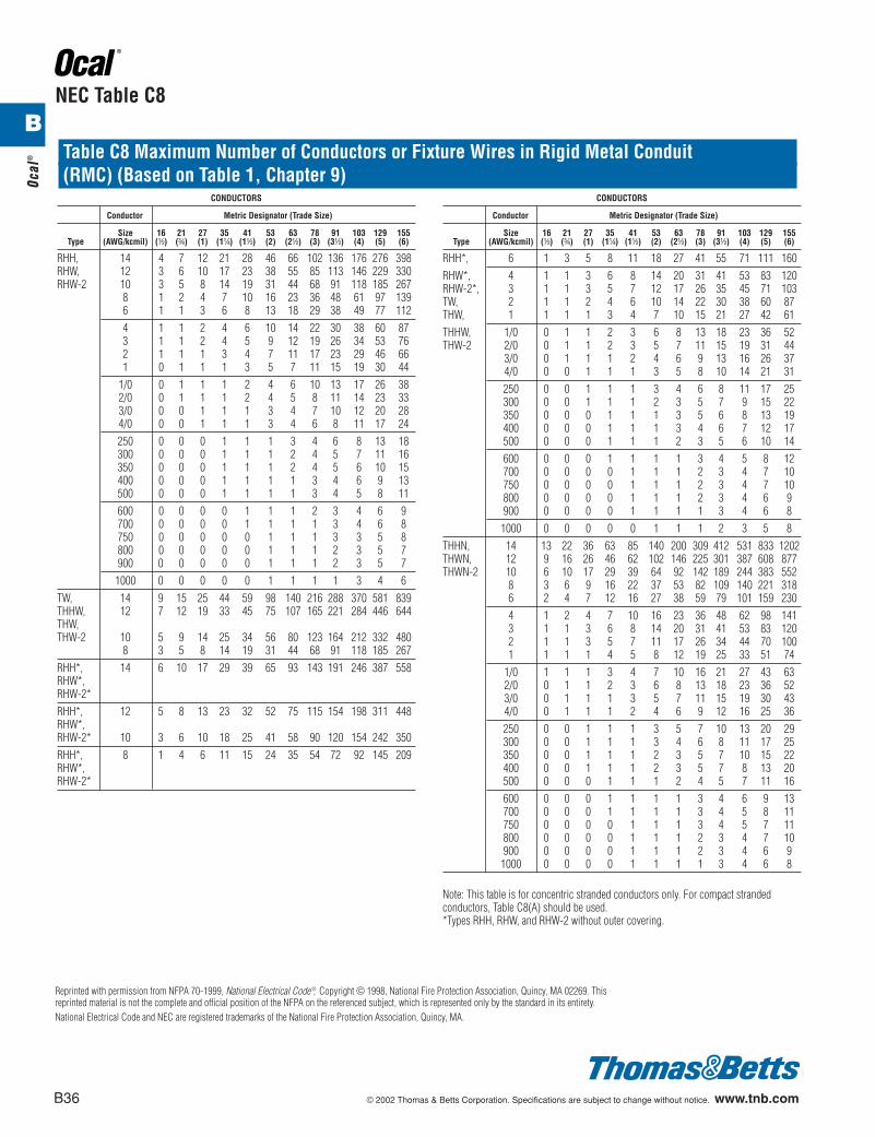
RHH, 14 4 7 12 21 28 46 66 102 136 176 276 398RHW, 12 3 6 10 17 23 38 55 85 113 146 229 330RHW-2 10 3 5 8 14 19 31 44 68 91 118 185 267
8 1 2 4 7 10 16 23 36 48 61 97 1396 1 1 3 6 8 13 18 29 38 49 77 1124 1 1 2 4 6 10 14 22 30 38 60 873 1 1 2 4 5 9 12 19 26 34 53 762 1 1 1 3 4 7 11 17 23 29 46 661 0 1 1 1 3 5 7 11 15 19 30 44
1/0 0 1 1 1 2 4 6 10 13 17 26 382/0 0 1 1 1 2 4 5 8 11 14 23 333/0 0 0 1 1 1 3 4 7 10 12 20 284/0 0 0 1 1 1 3 4 6 8 11 17 24250 0 0 0 1 1 1 3 4 6 8 13 18300 0 0 0 1 1 1 2 4 5 7 11 16350 0 0 0 1 1 1 2 4 5 6 10 15400 0 0 0 1 1 1 1 3 4 6 9 13500 0 0 0 1 1 1 1 3 4 5 8 11600 0 0 0 0 1 1 1 2 3 4 6 9700 0 0 0 0 1 1 1 1 3 4 6 8750 0 0 0 0 0 1 1 1 3 3 5 8800 0 0 0 0 0 1 1 1 2 3 5 7900 0 0 0 0 0 1 1 1 2 3 5 71000 0 0 0 0 0 1 1 1 1 3 4 6
TW, 14 9 15 25 44 59 98 140 216 288 370 581 839THHW, 12 7 12 19 33 45 75 107 165 221 284 446 644THW,THW-2 10 5 9 14 25 34 56 80 123 164 212 332 480
8 3 5 8 14 19 31 44 68 91 118 185 267RHH*, 14 6 10 17 29 39 65 93 143 191 246 387 558RHW*,RHW-2*RHH*, 12 5 8 13 23 32 52 75 115 154 198 311 448RHW*,RHW-2* 10 3 6 10 18 25 41 58 90 120 154 242 350RHH*, 8 1 4 6 11 15 24 35 54 72 92 145 209RHW*,RHW-2*
CONDUCTORS
Conductor Metric Designator (Trade Size)
Size 16 21 27 35 41 53 63 78 91 103 129 155Type (AWG/kcmil) (d) (f) (1) (1b) (1d) (2) (2d) (3) (3d) (4) (5) (6)
RHH*, 6 1 3 5 8 11 18 27 41 55 71 111 160RHW*, 4 1 1 3 6 8 14 20 31 41 53 83 120RHW-2*, 3 1 1 3 5 7 12 17 26 35 45 71 103TW, 2 1 1 2 4 6 10 14 22 30 38 60 87THW, 1 1 1 1 3 4 7 10 15 21 27 42 61THHW, 1/0 0 1 1 2 3 6 8 13 18 23 36 52THW-2 2/0 0 1 1 2 3 5 7 11 15 19 31 44
3/0 0 1 1 1 2 4 6 9 13 16 26 374/0 0 0 1 1 1 3 5 8 10 14 21 31250 0 0 1 1 1 3 4 6 8 11 17 25300 0 0 1 1 1 2 3 5 7 9 15 22350 0 0 0 1 1 1 3 5 6 8 13 19400 0 0 0 1 1 1 3 4 6 7 12 17500 0 0 0 1 1 1 2 3 5 6 10 14600 0 0 0 1 1 1 1 3 4 5 8 12700 0 0 0 0 1 1 1 2 3 4 7 10750 0 0 0 0 1 1 1 2 3 4 7 10800 0 0 0 0 1 1 1 2 3 4 6 9900 0 0 0 0 1 1 1 1 3 4 6 81000 0 0 0 0 0 1 1 1 2 3 5 8
THHN, 14 13 22 36 63 85 140 200 309 412 531 833 1202THWN, 12 9 16 26 46 62 102 146 225 301 387 608 877THWN-2 10 6 10 17 29 39 64 92 142 189 244 383 552
8 3 6 9 16 22 37 53 82 109 140 221 3186 2 4 7 12 16 27 38 59 79 101 159 2304 1 2 4 7 10 16 23 36 48 62 98 1413 1 1 3 6 8 14 20 31 41 53 83 1202 1 1 3 5 7 11 17 26 34 44 70 1001 1 1 1 4 5 8 12 19 25 33 51 74
1/0 1 1 1 3 4 7 10 16 21 27 43 632/0 0 1 1 2 3 6 8 13 18 23 36 523/0 0 1 1 1 3 5 7 11 15 19 30 434/0 0 1 1 1 2 4 6 9 12 16 25 36250 0 0 1 1 1 3 5 7 10 13 20 29300 0 0 1 1 1 3 4 6 8 11 17 25350 0 0 1 1 1 2 3 5 7 10 15 22400 0 0 1 1 1 2 3 5 7 8 13 20500 0 0 0 1 1 1 2 4 5 7 11 16600 0 0 0 1 1 1 1 3 4 6 9 13700 0 0 0 1 1 1 1 3 4 5 8 11750 0 0 0 0 1 1 1 3 4 5 7 11800 0 0 0 0 1 1 1 2 3 4 7 10900 0 0 0 0 1 1 1 2 3 4 6 91000 0 0 0 0 1 1 1 1 3 4 6 8
Note: This table is for concentric stranded conductors only. For compact strandedconductors, Table C8(A) should be used.*Types RHH, RHW, and RHW-2 without outer covering.
Table C8 Maximum Number of Conductors or Fixture Wires in Rigid Metal Conduit(RMC) (Based on Table 1, Chapter 9)
NEC Table C8
Reprinted with permission from NFPA 70-1999, National Electrical Code ®, Copyright © 1998, National Fire Protection Association, Quincy, MA 02269. Thisreprinted material is not the complete and official position of the NFPA on the referenced subject, which is represented only by the standard in its entirety.National Electrical Code and NEC are registered trademarks of the National Fire Protection Association, Quincy, MA.
412031.B01 OCAL 3/5 3/13/03 5:02 PM Page 36
© 2002 Thomas & Betts Corporation. Specifications are subject to change without notice. www.tnb.com B37
Ocal®
BSpecifications For OCAL-BLUE PVC Coated Galvanized Conduit and Fittings
1. All conduit prior to coating shall conform to:Federal Specification WW-C-581E, ANSI specificationC80.1 and UL 6.2. The conduit shall be “Hot Dipped” galvanizedinside and out with hot dipped galvanized threads. The“Hot Dipped” galvanized threads shall be coated withblue urethane. The zinc coating shall be intact &undistrubed.3. Conduits shall be investigated by UnderwritersLaboratories for both the zinc as the primary coatingand the PVC (polyvinyl chloride) as the primary coatingensuring double protection. Conduit shall be labeledwith the UL Label having only one exception requiringthe use of threaded fittings. No disclaimer.4. The interior of the conduit shall have a blueurethane coating of a nominal thickness of .002" (2 mils).5. The exterior of the conduit shall have PVCcoating of a minimum thickness of .040" (40 mils)applied by dipping in liquid plastisol.6. All coated conduit shall conform to NEMAStandard No. RN-1.7. The conduit shall be bendable without damageto either interior or exterior coating.8. A .002" (2 mils) nominal thickness coating ofblue urethane shall be applied to the exterior, theinterior, and the threads of all fittings.9. A .040" (40 mils) minimum thickness coating ofPVC shall be applied to the exterior of all fittings. ThePVC shall be applied using the plastisol method.10. Strut channel, strut fittings, and sheet metalenclosures. Shall have a thinner coat.11. The PVC coating on all form 8 fittings shall forma gasket-like flange of at least 5/16" wide and .040"thick covering the top of the fitting around the opening.12. The PVC coating on all form 8 covers shall forma gasket-like flange of at least 5/16" wide and .040"thick covering the bottom of the cover and mating withthe flange of the fitting.13. Stainless steel encapsulated screws shall besupplied with all form 7 and form 8 fittings.14. All hubs on fittings and couplings shall have aPVC sleeve extending one pipe diameter or 2 inches,whichever is less. The I.D. of the sleeve to be equal tothe O.D. of the uncoated pipe.15. The bond between the coatings and the metalshall be greater than the tensile strength of thecoatings.16. A loose coupling shall be supplied with eachlength of conduit. The couplings shall have longitudinalribs to enhance installation.
17. RA clamps shall have a minimum of 40 milcoating throughout. All nuts for RA clamps and U-boltsshall be encapsulated in a hexagon shape to fitstandard sockets.
General Properties for OCAL-BLUE PVC CoatedGalvanized Conduit and Fittings
Hardness85-90 Shore A
Dielectric Strength400 Volts/mil @ 60 Cycles
Aging1,000 hours Atlas Weatherometer
Elongation200%
TemperatureThe polyvinyl chloride compound shall conform at -10degrees Fahrenheit temperature to FederalSpecifications LP-406b, Method 2051, Amendment 1 of25 September 1952 (ASTMD-746). OCAL-BLUE is notrecommended for use in areas where it will be exposedto sustained temperatures above 200 degreesFahrenheit or exposed to fire.
FlammabilityIf subjected to sustained flame or sustained heat above400 degrees Fahrenheit, PVC will burn. PVC is self-extinguishing at room temperature.
ToxicityProlonged exposure to heat greater than 200 degreesFahrenheit or exposure to fire may cause the plasticcoatings to release harmful emissions posing apotential health hazard to persons subjected to suchemissions.
Bonding TestUsing a sharp knife make two parallel cuts through thecoating d" apart. Make a cut connecting those two cutsand work with a knife underneath the plastic to free aplastic tab. The tab shall be pulled with a pair of pliersaway from the pipe. The tab should tear leavingparticles of plastic on the metal surface indicating thebond is stronger than the tensile strength of thecoating.
412031.B01 OCAL 3/5 3/13/03 5:02 PM Page 37
B38 © 2002 Thomas & Betts Corporation. Specifications are subject to change without notice. www.tnb.com
OCAL Recommended Installation Procedures
PVC coated conduit is installed in much the samemanner as conventional rigid galvanized steel conduit;however, certain precautions must be taken tocompensate for the exterior coating and to assuresatisfactory results. By following these guidelines andby using the proper tools, a damage-free installationcan be obtained.
It is recommended that a yoke vise be used in the fieldfor clamping PVC coated conduit. When using a yokevise it is recommended that the standard hardenedsteel jaws be replaced with the specially designedOCAL JAW vice adapters that provide greater clampingforce to prevent the pipe from spinning during thethreading operation.
To hold conduit in any other vise, take two pieces ofrigid conduit one size larger than the coated conduit,6" – 8" long. Using a band saw, slice them the long wayslightly off center. Use the smaller slices as a shellaround the conduit (throw away the large ones). Thiswill grab onto a large area, allowing a strong gripwithout damage to the coating.
It is preferred that a roller-type cutter be used in cuttingthe conduit as it results in a b" exposed area of pipebefore the start of the PVC jacket. This will allow thethreader dies to engage the conduit more easily andlessen pressure at the clamped area.
OCAL offers an electric bender manufactured toaccommodate d" through 2" PVC coated conduitallowing damage-free bending.
For 2d" and larger sizes, a hydraulic bender isrecommended. Shoes especially designed for PVCcoated conduit are available from most manufacturers.
If existing rigid hydraulic shoes (not EMT) are to bemodified, acceptable results can be obtained bymachining .060" from the inside of the shoe.
To overcome any tendency of the conduit to slipvertically out of the shoe during the bending processand cause kinking, OCAL offers a pipe retainer clampwhich can be modified to the shoes of any type ofbender for sizes 2d" or larger.
A hacksaw or bandsaw will result in a flush cut of thePVC and conduit. In this instance it is recommended totaper-trim the PVC starting at b" from the cut. This“pencil-cut” will allow the threader dies to engage morereadily. If the end is not trimmed, additional pressurewill be required to engage the dies.
Use a reamer to remove any burrs or sharp edgescaused by the cutting operation.
Threading PVC coated conduit with RIDGID hand diesrequires modification to the dies. The inside diameter ofthe pipe guide of the die head must be machined out.120" to compensate for the PVC coating. Factorymodified die heads are available from your distributor.
After the new threads have been cut, it is important thatcorrosion protection be applied to the exposed metal. Adegreasing spray should be used to thoroughly cleanthe threads and the internal ream. After the threads arecompletely cleaned, liberally apply Kopr-Shield™
Compound per NEC article 300.6(a).
Ocal
®
B
412031.B01 OCAL 3/5 3/13/03 5:02 PM Page 38