Embed Size (px)
Citation preview
1. GENERAL INFORMATION
1-0
UXV 500
1 __________________________________________________________________________________
__________________________________________________________________________________
__________________________________________________________________________________
__________________________________________________________________________________
__________________________________________________________________________________
GENERAL INFORMATION__________________________________________________________________________________
SERIAL NUMBER---------------------------------------------------------- 1- 1SPECIFICATIONS ---------------------------------------------------------- 1- 2SERVICE PRECAUTIONS ------------------------------------------------ 1- 3TORQUE VALUES --------------------------------------------------------- 1-11SPECIAL TOOLS ----------------------------------------------------------- 1-15LUBRICATION POINTS -------------------------------------------------- 1-18
1
1. GENERAL INFORMATION
1-1
UXV 500
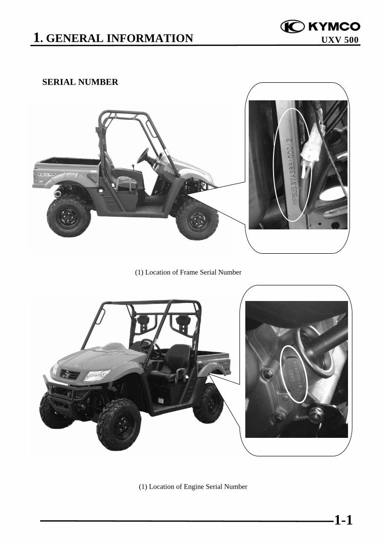
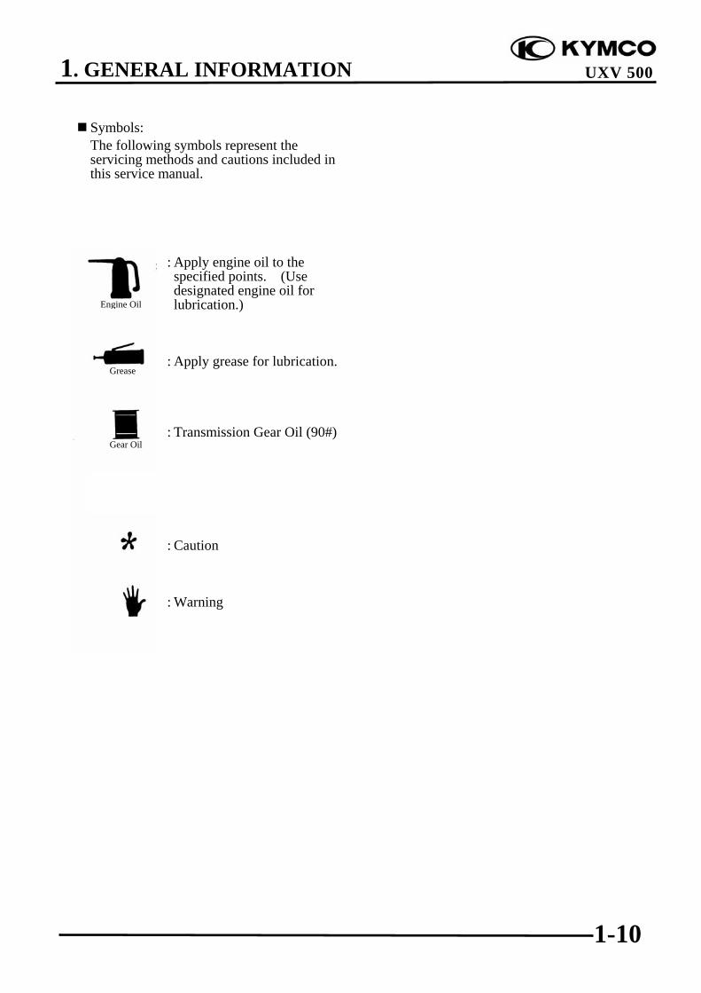
SERIAL NUMBER
(1) Location of Engine Serial Number
(1) Location of Frame Serial Number

1. GENERAL INFORMATION
1-2
UXV 500
SPECIFICATIONS
Model No. UAA0 seriesName & Type UXV 500Overall length 2870 mmOverall width 1500 mmOverall height 1850 mmWheel base 1910 mmEngine type D.O.H.C.Displacement 498.5 CCFuel used Nonleaded Gasoline
Front wheel 228 kgRear wheel 297kgDry weightTotal 525kgFront wheel 243 kgRear wheel 317 kgCurb weightTotal 560 kgFront wheel 25X8R-12TiresRear wheel 25X10R-12
Ground clearance 310 mm (12.2 in)Min. turning radius 4350 mm (170 in)
Starting systemElectric/Recoilstarter
Type Gasoline, 4-strokeCylinder arrangement Single cylinderCombustion chamber type Semi-sphereValve arrangement O.H.C., chain drive
Bore x stroke92X75 mm(3.68X3 in)
Compression ratio 10.5:1
Compression pressure 15 kgf/cm²(1500kPa, 213 psi)
Opens 5° BTDCIntake valve(at 1mm lift) Closes 45° ABDC
Opens 45° BBDCExhaust valve(at 1mm lift) Closes 5° ATDC
Intake 0.1 mm (0.004 in)Valve clearance(cold) Exhaust 0.1 mm (0.004 in)Idle speed (rpm) 1500 rpmCooling type Liquid cooled
Lubrication type Forced pressure &Wet sump
Oil pump type TrochoidOil filter type Full-flow filtration
Oil capacity 3.6 L
Oil exchanging capacity 3 L
After draining and oilfilter cartridge change
3.2 L
Air cleaner type & No Wet type element
Fuel capacity 32 L
Type CVKON ROAD #124Main
jet OFF ROAD #122Slow jet #40Choke jet #90
Type Full transistor digitalignition
Ignition timing 5°/1500 rpmSpark plug CR7E (NGK)
Spark plug gap 0.6~0.7mm
Battery Capacity 12V18AH
Clutch type Wet, centrifugalautomatic
Clutch operation system Automatic (V-belt)Primary reduction system V-beltSecondary reductionsystem Shaft drive
High reduction ratio 3.48Low reduction ratio 6.464Reverse ratio 5.31FR/RR tire rollingcircumference
1995/1995 mm(79.8/79.8 in)
FrontTire pressure
(1person 75kg)Rear
0.7/0.98 kgf/cm²(10/14 psi)(FR/RR)
Left 38.8°Turning angleRight 38.8°
Front Disk brakeBrake system typeRear Disk brakeFront Double A-armSuspension typeRear Double A-arm
Frame type Double cradle
Engine
Ignition System
Drive Train
Moving D
eviceLubrication System
Fuel System
Carbureto r
Electrical Equipment

1. GENERAL INFORMATION
1-3
UXV 500
SERVICE PRECAUTIONS
Make sure to install new gaskets, O-rings,circlips, cotter pins, etc. when reassembling.
When tightening bolts or nuts, begin withlarger-diameter to smaller ones at severaltimes, and tighten to the specified torquediagonally.
Use genuine parts and lubricants.
When servicing the motorcycle, be sure touse special tools for removal andinstallation.
After disassembly, clean removed parts.Lubricate sliding surfaces with engine oilbefore reassembly.

1. GENERAL INFORMATION
1-4
UXV 500
Apply or add designated greases andlubricants to the specified lubricationpoints.
After reassembly, check all parts for propertightening and operation.
When two persons work together, payattention to the mutual working safety.
Disconnect the battery negative (-) terminalbefore operation.When using a spanner or other tools, makesure not to damage the motorcycle surface.
After operation, check all connecting points,fasteners, and lines for proper connectionand installation.When connecting the battery, the positive (+)terminal must be connected first.After connection, apply grease to the batteryterminals.Terminal caps shall be installed securely.
(-)
(+)

1. GENERAL INFORMATION
1-5
UXV 500
If the fuse is burned out, find the cause andrepair it. Replace it with a new oneaccording to the specified capacity.
After operation, terminal caps shall beinstalled securely.
When taking out the connector, the lock onthe connector shall be released beforeoperation.
Hold the connector body when connectingor disconnecting it.Do not pull the connector wire.
Check if any connector terminal is bending,protruding or loose.
ConfirmCapacity

1. GENERAL INFORMATION
1-6
UXV 500
The connector shall be insertedcompletely.If the double connector has a lock, lock itat the correct position.Check if there is any loose wire.
Before connecting a terminal, check fordamaged terminal cover or loosenegative terminal.
Check the double connector cover forproper coverage and installation.
Insert the terminal completely.Check the terminal cover for propercoverage.Do not make the terminal cover openingface up.
Secure wire harnesses to the frame withtheir respective wire bands at the designatedlocations.Tighten the bands so that only the insulatedsurfaces contact the wire harnesses.
Snapping!

1. GENERAL INFORMATION
1-7
UXV 500
After clamping, check each wire to makesure it is secure.
Do not squeeze wires against the weld or itsclamp.
After clamping, check each harness to makesure that it is not interfering with anymoving or sliding parts.
When fixing the wire harnesses, do notmake it contact the parts which willgenerate high heat.
Route wire harnesses to avoid sharp edgesor corners. Avoid the projected ends ofbolts and screws.Route wire harnesses passing through theside of bolts and screws. Avoid theprojected ends of bolts and screws.
No Contact !

1. GENERAL INFORMATION
1-8
UXV 500
Route harnesses so they are neitherpulled tight nor have excessive slack.
Protect wires and harnesses with electricaltape or tube if they contact a sharp edge orcorner.
When rubber protecting cover is used toprotect the wire harnesses, it shall beinstalled securely.
Do not break the sheath of wire.If a wire or harness is with a broken sheath,repair by wrapping it with protective tape orreplace it.
When installing other parts, do not press orsqueeze the wires.
Do not pulltoo tight!
Do not press orsqueeze the wire.

1. GENERAL INFORMATION
1-9
UXV 500
After routing, check that the wire harnessesare not twisted or kinked.
Wire harnesses routed along with handlebarshould not be pulled tight, have excessiveslack or interfere with adjacent orsurrounding parts in all steering positions.
When a testing device is used, make sure tounderstand the operating methodsthoroughly and operate according to theoperating instructions.
Be careful not to drop any parts.
When rust is found on a terminal, removethe rust with sand paper or equivalentbefore connecting.
Do you understandthe instrument? Is theinstrument setcorrectly?
Remove Rust !
1. GENERAL INFORMATION
1-10
UXV 500
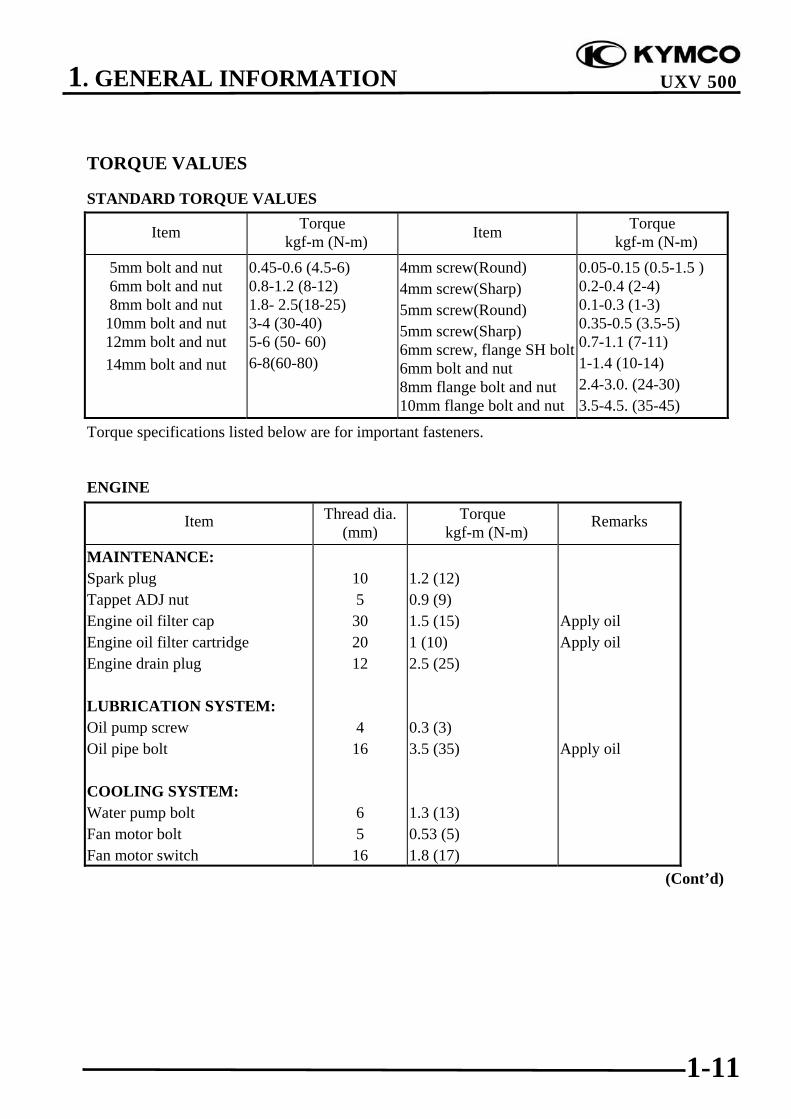
Symbols:The following symbols represent theservicing methods and cautions included inthis service manual.
: Apply engine oil to thespecified points. (Usedesignated engine oil forlubrication.)
: Apply grease for lubrication.
: Transmission Gear Oil (90#)
: Caution
: Warning
Engine Oil
Grease
Gear Oil
1. GENERAL INFORMATION
1-11
UXV 500
TORQUE VALUES
STANDARD TORQUE VALUES
Item Torque kgf-m (N-m) Item Torque
kgf-m (N-m)5mm bolt and nut6mm bolt and nut8mm bolt and nut
10mm bolt and nut12mm bolt and nut14mm bolt and nut
0.45-0.6 (4.5-6)0.8-1.2 (8-12)1.8- 2.5(18-25)3-4 (30-40)5-6 (50- 60)6-8(60-80)
4mm screw(Round)4mm screw(Sharp)5mm screw(Round)5mm screw(Sharp)6mm screw, flange SH bolt6mm bolt and nut8mm flange bolt and nut10mm flange bolt and nut
0.05-0.15 (0.5-1.5 )0.2-0.4 (2-4)0.1-0.3 (1-3)0.35-0.5 (3.5-5)0.7-1.1 (7-11)1-1.4 (10-14)2.4-3.0. (24-30)3.5-4.5. (35-45)
Torque specifications listed below are for important fasteners.
ENGINE
Item Thread dia.(mm)
Torque kgf-m (N-m)
Remarks
MAINTENANCE:Spark plugTappet ADJ nutEngine oil filter capEngine oil filter cartridgeEngine drain plug
LUBRICATION SYSTEM:Oil pump screwOil pipe bolt
COOLING SYSTEM:Water pump boltFan motor boltFan motor switch
105
302012
416
65
16
1.2 (12)0.9 (9)1.5 (15)1 (10)2.5 (25)
0.3 (3)3.5 (35)
1.3 (13)0.53 (5)1.8 (17)
Apply oilApply oil
Apply oil
(Cont’d)

1. GENERAL INFORMATION
1-12
UXV 500
Item Thread dia.(mm)
Torque kgf-m (N-m)
Remarks
CYLINDER HEAD:Cylinder head boltCylinder head boltCylinder head nutCylinder head coverBreather separator boltCam chain tensioner boltTensioner sealing boltRocker arm shaftChain guide pivot boltWater joint bolt
CYLINDER:Cylinder bolt
DRIVE/DRIVEN PULLEY:Drive pulley nutWet clutch nutDriven pulley nutDriven pulley assembly plate nut
TRANSMISSION:Crankcase boltDrive bevel gear nutDriven bevel gear nutStopper lever boltStopper lever boss nutShift came stopper plugOutput shaft bearing nutDrive shaft bearing bolt
STARTER SYSTEM:Starter pulley nut
1086666
101886
6
20251636
620208
1220858
14
4.8 (48)2.3 (23)1 (10)1 (10)1.3 (13)1.2 (12)1 (10)4.5 (45)2 (20)1.2 (12)
1 (10)
14 (140)14 (140)10 (100)7.5 (75)
1.2 (12)14 (140)14 (140)2.5 (25)3 (30)4.8 (48)11 (110)3 (30)
5.5 (55)
Apply oilApply oil
Apply oil
Apply oil
Apply oil
Apply oilApply oilApply oil
Apply oil

1. GENERAL INFORMATION
1-13
UXV 500
FRAME
Item Q‘ty Threaddia.
(mm)
Torque Kgf-m (N-m,
lbf-ft)Remarks
STEERING:Steering column and intermediate shaftSteering assembly and intermediate shaftSteering assembly and frameSteering column assembly and frameSteering wheel and steering columnFront knuckle and front upper armFront knuckle and front lower armTie-rod lock nutFront knuckle and Tie-rod
WHEEL:Front wheel and front wheel hubRear wheel and rear wheel hubFront wheel hub and cvjRear wheel hub and cvj
FR SUSPENSION:Front upper arm and frameFront lower arm and frameFront shock absorber and frameFront shock absorber and front upper armRR SUSPENSION:Rear upper arm and frameRear lower arm and frameRear knuckle and rear upper armRear knuckle and rear lower armRear shock cushion and frameRear shock cushion and rear lower armStabilizer and frameStabilizer joint and stabilizerStabilizer joint and rear lower arm
88
10101210101210
10101818
10101010
101010101010101010
2.7 (27, 15)2.7 (27,15)4.8 (48, 34)3.2 (32, 23)3.5 (35 25.)4.8 (48 ,34)4.8 (48 ,34)4.0 (40, 28)3.5 (35, 25)
5.5 (55, 39)5.5 (55, 39)20 (200, 160)20(200,160)
4.8(48,34)4.8(48,34)4.5(45,32.4)4.5 (45, 32.4)
4.8 (48, 34)4.8 (48, 34)4.8 (48, 34)4.8 (48, 34)4.5 (45, 32)4.5 (45, 32)3.2(32, 23)5.5(55,39)5.5(55,39)
(Cont’d)
1. GENERAL INFORMATION
1-14
UXV 500
Item Q‘ty Threaddia.
(mm)
TorqueKgf-m (N-m,
lbf-ft)Remarks
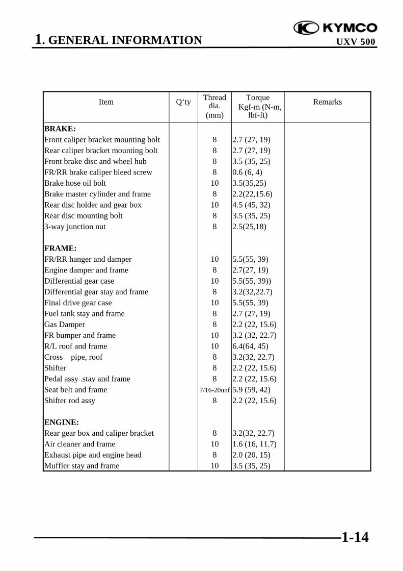
BRAKE:Front caliper bracket mounting boltRear caliper bracket mounting boltFront brake disc and wheel hubFR/RR brake caliper bleed screwBrake hose oil boltBrake master cylinder and frameRear disc holder and gear boxRear disc mounting bolt3-way junction nut
FRAME:FR/RR hanger and damperEngine damper and frameDifferential gear caseDifferential gear stay and frameFinal drive gear caseFuel tank stay and frameGas DamperFR bumper and frameR/L roof and frameCross pipe, roofShifterPedal assy .stay and frameSeat belt and frameShifter rod assy
ENGINE:Rear gear box and caliper bracketAir cleaner and frameExhaust pipe and engine headMuffler stay and frame
8888
108
1088
108
108
1088
1010888
7/16-20unf8
8108
10
2.7 (27, 19)2.7 (27, 19)3.5 (35, 25)0.6 (6, 4)3.5(35,25)2.2(22,15.6)4.5 (45, 32)3.5 (35, 25)2.5(25,18)
5.5(55, 39)2.7(27, 19)5.5(55, 39))3.2(32,22.7)5.5(55, 39)2.7 (27, 19)2.2 (22, 15.6)3.2 (32, 22.7)6.4(64, 45)3.2(32, 22.7)2.2 (22, 15.6)2.2 (22, 15.6)5.9 (59, 42)2.2 (22, 15.6)
3.2(32, 22.7)1.6 (16, 11.7)2.0 (20, 15)3.5 (35, 25)

1. GENERAL INFORMATION
1-15
UXV 500
SPECIAL TOOLS
Tool Name Tool No.
Illustration(Note: the special tools may differ
slightly from those shown in thefigure of this manual.)
Oil seal and bearinginstaller A120E00014
Valve adjuster
(Refer to the “VALVECLEARANCE” section in thechapter 3.)
A120E00036
Bearing puller A120E00037
Valve spring compressor
(Refer to the “CYLINDER HEADDISASSEMBLY/INSPECTION/ASSEMBLY” section in thechapter 8.)
A120E00040
Universal holder
(Refer to the “DRIVE PULLEY,DRIVE V-BELT AND DRIVENPULLEYREMOVAL/INSPECTION/INSTALLATION” section and“CLUTCH REMOVAL/INSTALLATION” section in thechapter 10.)
A120E00056
Drive pulley holder
(Refer to the “DRIVE PULLEY,DRIVE V-BELT AND DRIVENPULLEYREMOVAL/INSPECTION/INSTALLATION” section in thechapter 10.)
A120E00058
1. GENERAL INFORMATION
1-16
UXV 500
Tool Name Tool No.
Illustration(Note: the special tools may differ
slightly from those shown in thefigure of this manual.)
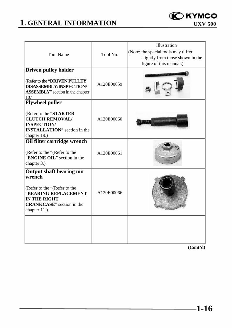
Driven pulley holder
(Refer to the “DRIVEN PULLEYDISASSEMBLY/INSPECTION/ASSEMBLY” section in the chapter10.)
A120E00059
Flywheel puller
(Refer to the “STARTERCLUTCH REMOVAL/INSPECTION/INSTALLATION” section in thechapter 19.)
A120E00060
Oil filter cartridge wrench
(Refer to the “(Refer to the“ENGINE OIL” section in thechapter 3.)
A120E00061
Output shaft bearing nutwrench
(Refer to the “(Refer to the“BEARING REPLACEMENTIN THE RIGHTCRANKCASE” section in thechapter 11.)
A120E00066
(Cont’d)
1. GENERAL INFORMATION
1-17
UXV 500
Tool Name Tool No.
Illustration(Note: the special tools may differ
slightly from those shown in thefigure of this manual.)
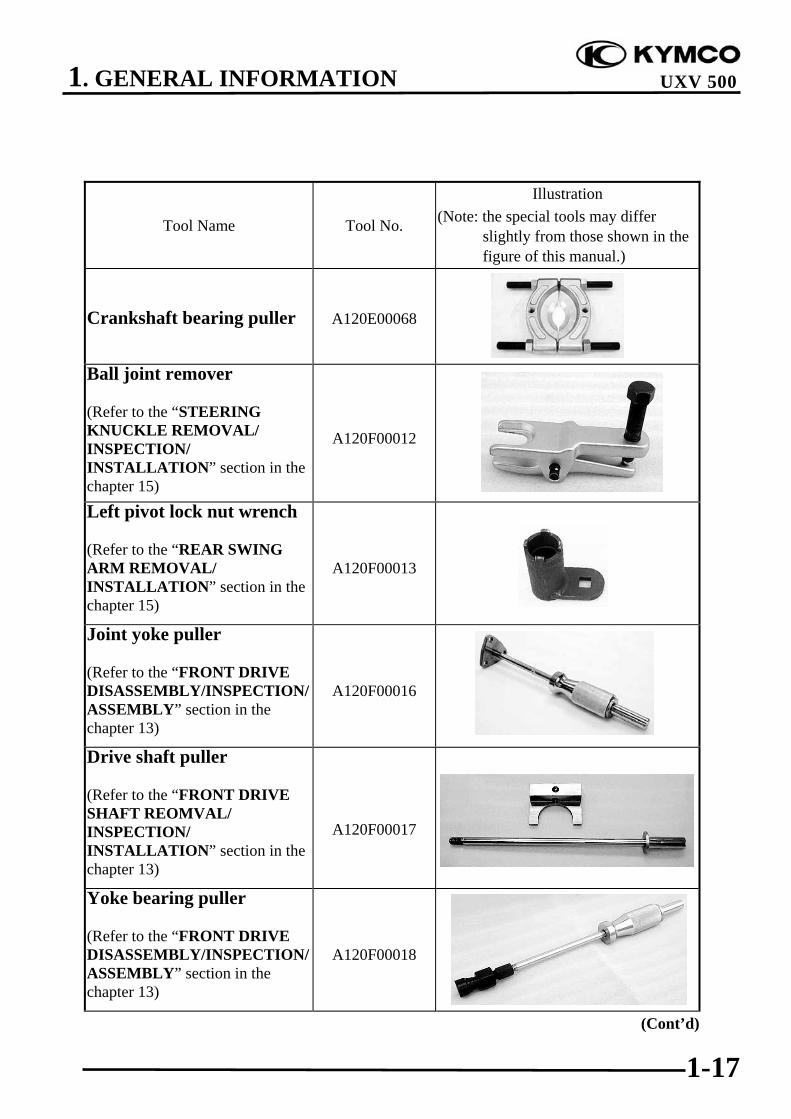
Crankshaft bearing puller A120E00068
Ball joint remover
(Refer to the “STEERINGKNUCKLE REMOVAL/INSPECTION/INSTALLATION” section in thechapter 15)
A120F00012
Left pivot lock nut wrench
(Refer to the “REAR SWINGARM REMOVAL/INSTALLATION” section in thechapter 15)
A120F00013
Joint yoke puller
(Refer to the “FRONT DRIVEDISASSEMBLY/INSPECTION/ASSEMBLY” section in thechapter 13)
A120F00016
Drive shaft puller
(Refer to the “FRONT DRIVESHAFT REOMVAL/INSPECTION/INSTALLATION” section in thechapter 13)
A120F00017
Yoke bearing puller
(Refer to the “FRONT DRIVEDISASSEMBLY/INSPECTION/ASSEMBLY” section in thechapter 13)
A120F00018
(Cont’d)

1. GENERAL INFORMATION
1-18
UXV 500
Tool Name Tool No.
Illustration(Note: the special tools may differ
slightly from those shown in thefigure of this manual.)
Pinion bearing lock nutwrench
(Refer to the “REAR DRIVEDISASSEMBLY/INSPECTION/ASSEMBLY” section in the chapter13.)
A120F00020
Pinion puller
(Refer to the “REAR DRIVEDISASSEMBLY/INSPECTION/ASSEMBLY” section in the chapter13.)
A120F00021
C-ring remover
(Refer to the “FRONT DRIVEDISASSEMBLY/INSPECTION/ASSEMBLY” section in thechapter 13)
A120F00022
Carburetor adjustmentAdjust pilot screw position
A120E00076

1. GENERAL INFORMATION
1-19
UXV 500
LUBRICATION POINTS
ENGINE
Lubrication Points Lubricant Valve guide/valve stem movable part Camshaft protruding surface Valve rocker arm friction surface Camshaft drive chain Cylinder lock bolt Piston surroundings and piston ring grooves Piston pin surroundings Cylinder inside wall Connecting rod/piston pin hole Connecting rod big end Clutch Crankshaft Balance shaft Crankshaft one-way clutch movable part Recoil starter pulley Oil pump drive chain Starter reduction gear Starter one-way clutch O-ring face Oil seal lip Output shaft Bevel gear Drive shaft Countershaft Main shaft Transmission gear shaft bearing part
•Genuine KYMCO Engine Oil (SAE10W-30) •API SJ Engine Oil
Front drive gear and bearing part Gear oil: SAE 80-90#Rear drive gear and bearing part Gear oil: SAE 80-90#
2. FRAME COVERS/EXHAUST MUFFLER
2-0
UXV 500
2 __________________________________________________________________________________
__________________________________________________________________________________
__________________________________________________________________________________
__________________________________________________________________________________
__________________________________________________________________________________
FRAME COVERS/EXHAUST MUFFLER__________________________________________________________________________________
SERVICE INFORMATION------------------------------------------------ 2- 1TROUBLESHOOTING----------------------------------------------------- 2- 1UXV 500 REMOVAL AND REINSTALLATION --------------------- 2- 2FRAME COVERS ----------------------------------------------------------- 2- 3EXHAUST MUFFLER ----------------------------------------------------- 2- 11
2

2. FRAME COVERS/EXHAUST MUFFLER
2-1
UXV 500
SERVICE INFORMATION
GENERAL INSTRUCTIONS• When removing frame covers, use special care not to pull them by force because the cover joint
claws may be damaged.• Make sure to route cables and harnesses according to the Cable & Harness Routing.
TORQUE VALUESExhaust muffler mounting bolt 3.5 kgf-m (35 Nm, 25 lbf-ft)Exhaust pipe mounting nut 3.5 kgf-m (35 Nm, 25 lbf-ft)Exhaust muffler band bolts 2.1 kgf-m (21 N-m, 15 lbf-ft)
TROUBLESHOOTINGNoisy exhaust muffler• Damaged exhaust muffler• Exhaust muffler joint air leaksLack of power• Caved exhaust muffler• Exhaust muffler air leaks• Clogged exhaust muffler

2. FRAME COVERS/EXHAUST MUFFLER
2-2
UXV 500
UXV 500 REMOVAL ANDREINSTALLATION
REMOVALDepress the head of plastic screws centerpiece .Pull out the .plastic screws
INSTALLATIONLet the center piece stick out toward thehead so that the pawls close.Insert the plastic screws into the installationhole.
Push in the head of center piece until itbecomes flush with the plastic screwsoutside face.
To prevent the pawl from damage,insert the fastener all the way into theinstallation hole
*
Up position function is disconnect(need use screwdriver)Down position function is lock.

2. FRAME COVERS/EXHAUST MUFFLER
2-3
UXV 500
FRAME COVERS
SEAT
REMOVAL
To remove the seat, pull the seat lockboard , upward and pull up the seat.
INSTALLATION
To install the seat, into the seat stay thenPress the seat lock board
HOOD
REMOVAL/INSTALLATION
Remove hood’s L/R side plastic screws andlatchesSlowly tilt the hood until stop.Disconnect the 3 bolts and headlightconnecterRemove the hood.Installation is in the reverse order ofremoval.
Lock boardSeat stay

2. FRAME COVERS/EXHAUST MUFFLER
2-4
UXV 500
FRONT BUMPER COVER
REMOVAL/INSTALLATION
Remove the 4 bolts from the front Bumpercover, then remove the front bumper cover.
Installation is in the reverse order ofremoval.
UNDER COVER
REMOVAL/INSTALLATION
Remove the 6 bolts from the under cover,then remove the under cover.
Installation is in the reverse order ofremoval.
2. FRAME COVERS/EXHAUST MUFFLER
2-5
UXV 500
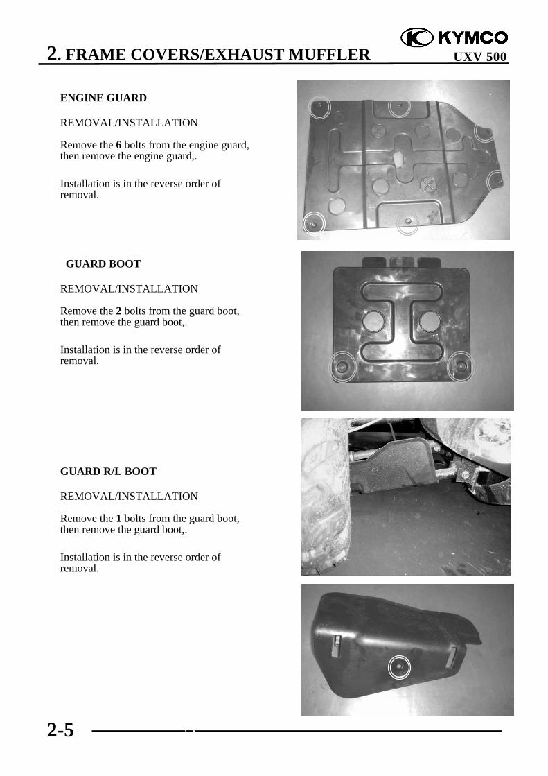
ENGINE GUARD
REMOVAL/INSTALLATION
Remove the 6 bolts from the engine guard,then remove the engine guard,.
Installation is in the reverse order ofremoval.
GUARD BOOT
REMOVAL/INSTALLATION
Remove the 2 bolts from the guard boot,then remove the guard boot,.
Installation is in the reverse order ofremoval.
GUARD R/L BOOT
REMOVAL/INSTALLATION
Remove the 1 bolts from the guard boot,then remove the guard boot,.
Installation is in the reverse order ofremoval.

2. FRAME COVERS/EXHAUST MUFFLER
2-6
UXV 500
CENTER ASSY COVER
REMOVAL/INSTALLATIONRemove the 2 seatsRemove the 1 bolts from the gear shaftlever,Remove the 2 bolts from the center cover,then remove the center cover,.
Installation is in the reverse order ofremoval.
SIDE PANEL R/L FOOTREST
REMOVAL/INSTALLATION
Remove the 3 bolts from the side panel L/Rfootrest, then remove the side panel L/Rfootrest,.
Installation is in the reverse order ofremoval.

2. FRAME COVERS/EXHAUST MUFFLER
2-7
UXV 500
PANEL R/L SIDE AND PROTECTORSIDE
REMOVAL/INSTALLATION
Remove the 4 bolts from the panel L/Rside, then,. Remove the 7 bolts from theprotector side..
remove the panel L/R side andprotector side
Installation is in the reverse order ofremoval.
.
SIDE PANEL R/L FRONT
REMOVAL/INSTALLATION
Remove the 5 bolts from the side panel L/Rfront, then,.remove the side panel L/R front
Installation is in the reverse order ofremoval.

2. FRAME COVERS/EXHAUST MUFFLER
2-8
UXV 500
PEDAL PLATE
SUPPORT R/L SIDE PANDEL
TUNNER COVER
BRAKE PLATERemove brake lever bolt.Remove brake plate 6 bolts.
2. FRAME COVERS/EXHAUST MUFFLER
2-9
UXV 500
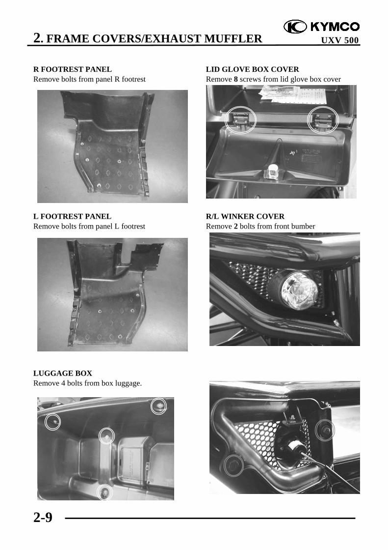
R FOOTREST PANELRemove bolts from panel R footrest
L FOOTREST PANELRemove bolts from panel L footrest
LUGGAGE BOXRemove 4 bolts from box luggage.
LID GLOVE BOX COVERRemove 8 screws from lid glove box cover
R/L WINKER COVERRemove 2 bolts from front bumber

2. FRAME COVERS/EXHAUST MUFFLER
2-10
UXV 500
FRONT PANELRemove steering wheel.Remove connecters and wires from panel front.Remove 4 bolts from panel front.Remove panel front.Installation is in the reverse order of removal.

2. FRAME COVERS/EXHAUST MUFFLER
2-11
UXV 500
EXHAUST MUFFLER REMOVAL
Loosen the exhaust pipe band bolt.Remove two muffler mounting bolts.
Remove the muffler and gasket from theexhaust pipe
Remove the exhaust muffler body andstay ,exhaust muffler pipe joint nuts.
Exhaust Muffler
Gasket
2. FRAME COVERS/EXHAUST MUFFLER
2-12
UXV 500
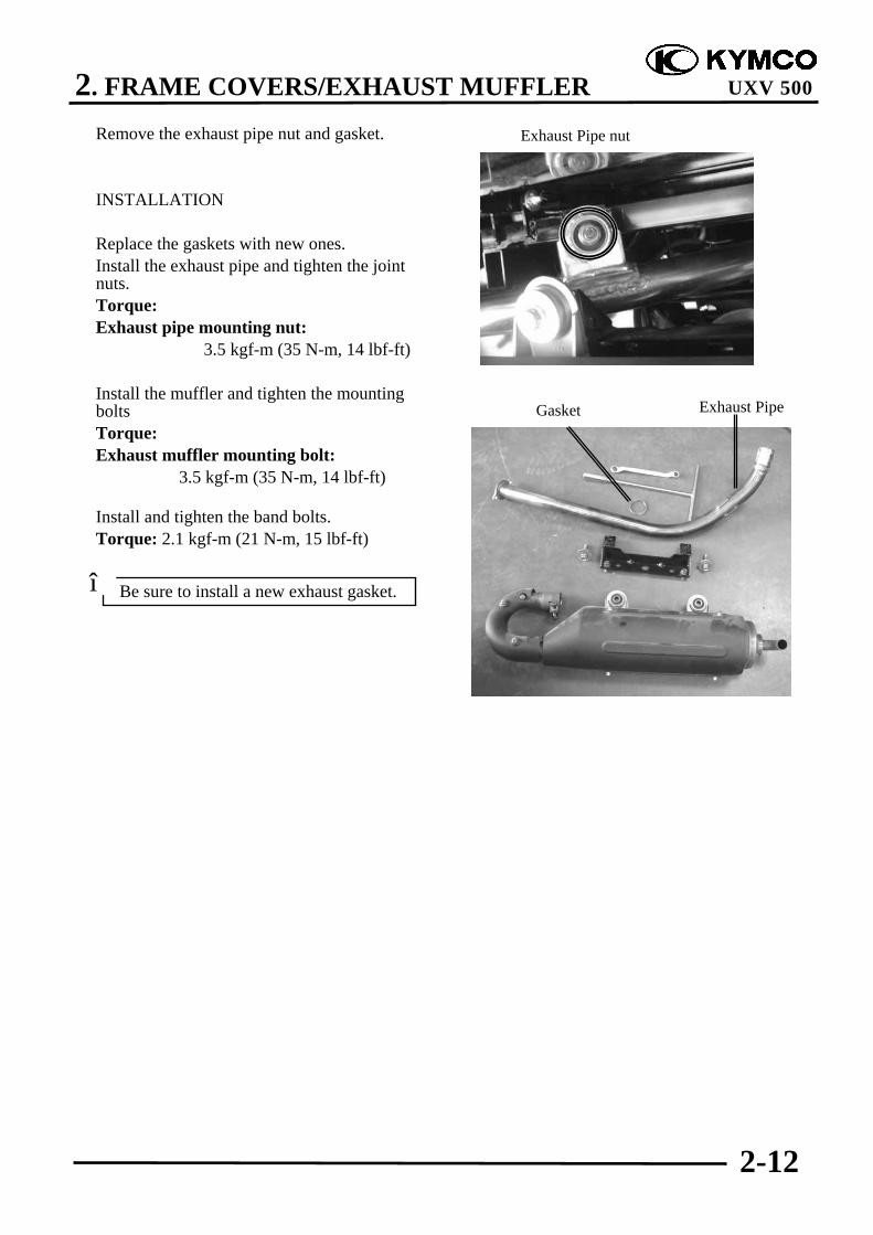
Remove the exhaust pipe nut and gasket.
INSTALLATION
Replace the gaskets with new ones.Install the exhaust pipe and tighten the jointnuts.Torque:Exhaust pipe mounting nut:
3.5 kgf-m (35 N-m, 14 lbf-ft)
Install the muffler and tighten the mountingboltsTorque:Exhaust muffler mounting bolt:
3.5 kgf-m (35 N-m, 14 lbf-ft)
Install and tighten the band bolts.Torque: 2.1 kgf-m (21 N-m, 15 lbf-ft)
Exhaust Pipe nut
Be sure to install a new exhaust gasket.*
Gasket Exhaust Pipe
3. INSPECTION/ADJUSTMENT
3-0
UXV 500
3 __________________________________________________________________________________
__________________________________________________________________________________
__________________________________________________________________________________
INSPECTION/ADJUSTMENT__________________________________________________________________________________
SERVICE INFORMATION------------------------------------------------ 3- 1MAINTENANCE SCHEDULE-------------------------------------------- 3- 3FUEL LINE/THROTTLE OPERATION--------------------------------- 3- 4SPEED LIMITER/AIR CLEANER --------------------------------------- 3- 5AIR BOX FOR DRIVE BELT --------------------------------------------- 3- 7SECONDARY AIR SUPPLY SYSTEM --------------------------------- 3- 8SPARK PLUG---------------------------------------------------------------- 3- 9VALVE CLEARANCE ----------------------------------------------------- 3-11CARBURETOR IDLE SPEED -------------------------------------------- 3-12CLINDER COMPRESSION/ENGINE OIL ----------------------------- 3-13REAR DRIVE GEAR OIL ------------------------------------------------- 3-17FRONT DRIVE GEAR OIL------------------------------------------------ 3-18SPARK ARRESTER -------------------------------------------------------- 3-19DRIVE SHAFT BOOTS ---------------------------------------------------- 3-20DRIVE BELT/BRAKE PADS INSPECTION --------------------------- 3-21BRAKE FLUID INSPECTION/HEADLIGHT AIM ------------------- 3-22STEERING SYSTEM INSPECTION------------------------------------- 3-23TOE-IN ADJUSTMENT --------------------------------------------------- 3-24WHEELS/TIRES ------------------------------------------------------------ 3-25COOLING SYSTEM-------------------------------------------------------- 3-28PARKING BRAKE ADJUSTMENT ------------------------------------- 3-29
3
3. INSPECTION/ADJUSTMENT
3-1
UXV 500
SERVICE INFORMATION
GENERAL
! WARNING•Before running the engine, make sure that the working area is well-ventilated. Never run theengine in a closed area. The exhaust contains poisonous carbon monoxide gas which maycause death to people.•Gasoline is extremely flammable and is explosive under some conditions. The working areamust be well-ventilated and do not smoke or allow flames or sparks near the working area orfuel storage area.
SPECIFICATIONS
Throttle grip free play : 3~5 mm (0.12~0.2 in)
Spark plug gap : 0.6~0.7 mm (0.024~0.028 in)
Spark plug: Standard : CR7E (NGK)
Valve clearance : IN: 0.1 mm (0.004 in)EX: 0.1 mm (0.004 in)
Idle speed : 1500±100 rpm
Engine oil capacity At disassembly : 3.6 liter (3.17 lmp qt, 3.82 Us qt) At change : 3 liter (2.64 lmp qt, 3.18 Us qt) After draining and oil filter cartridge change: 3.2 liter (2.82 lmp qt, 3.39 Us qt)
Front drive gear oil Recommended oil: SAE 80~90 At disassembly: 270 cc (10.6 lmp oz, 10.1 Us oz) At change: 270 cc (10.6 lmp qt, 10.1 Us qt)
Rear drive gear oil Recommended oil: SAE 80~90 At disassembly: 250 cc (5.33 lmp oz, 5 Us oz) At change: 250 cc (4.63 lmp qt, 4.33 Us qt)
Cylinder compression: 15 kg/cm² (1500 kPa, 213 psi)
Ignition timing: 5°±1°/1500 rpm

3. INSPECTION/ADJUSTMENT
3-2
UXV 500
Tire pressure
1 RiderFront 0.7 kgf/cm² (10 psi)Rear 0.98 kgf/cm² (14 psi)
Tire size: Front : 25X8-12 Rear : 25X10-12
TORQUE VALUES Spark plug 1.2kgf-m (12 N-m, 8.6 lbf-ft) Tappet ADJ nut 0.9 kgf-m (9 N-m, 6.5 lbf-ft) Engine oil filter cap 1.5 kgf-m (15 N-m, 11 lbf-ft) Engine oil filter cartridge 1 kgf-m (10 N-m, 7.2 lbf-ft) Engine oil drain plug 2.5 kgf-m (25 N-m, 18 lbf-ft) Rear drive gear oil drain bolt 2 kgf-m (20 N-m, 15 lbf-ft) Rear drive gear oil level check bolt 2 kgf-m (20 N-m, 15 lbf-ft) Rear drive gear oil filler cap 1.5 kgf-m (15 N-m, 11 lbf-ft) Front drive gear oil drain bolt 3.2 kgf-m (32 N-m, 23 lbf-ft) Front drive gear oil filler cap 3.5 kgf-m (35 N-m, 25.5 lbf-ft) Front drive gear oil level check bolt 1 kgf-m (10 N-m, 7.2 lbf-ft) Tie-rod adjusting nut 3.5 kgf-m (35 N-m, 25.2 lbf-ft) Front wheel hub nut 7 kgf-m (70 N-m, 50 lbf-ft) Rear wheel hub nut 10 kgf-m (100 N-m, 72 lbf-ft)
SPECIAL TOOLSValve adjusting wrench A120E00036Oil cartridge wrench A120E00061

3. INSPECTION/ADJUSTMENT
3-3
UXV 500
MAINTENANCE SCHEDULEThis chapter includes all information necessary to perform recommended inspections andadjustments. These preventive maintenance procedures, if followed, will ensure more reliablevehicle operation and a longer service life. The need for costly overhaul work will be greatlyreduced. This information applies to vehicles already in service ad well as new vehicles that arebeing prepared for sale. All service technicians should be familiar with this entire chapter.

3. INSPECTION/ADJUSTMENT
3-4
UXV 500
FUEL LINE
Check the fuel tubes and replace any parts,which show signs of deterioration, damageor leakage.
THROTTLE OPERATION
Check the throttle to swing for smoothmovement.Measure the throttle to swing free play.Free Play (A): 3~5 mm (0.12~0.2 in)
To adjust throttle free play:
1. Slide the rubber sleeve (1) back to exposethe throttle cable adjuster (2).
2. Loosen the lock nut (3), then turn theadjuster to obtain the correct free play.(3~5 mm or 0.12~0.2 in)
3. Tighten the lock nut and reinstall thesleeve.
Other checks:Check the throttle cable for kinks and signsof wear that could cause stretching orfailure. Lubricate the throttle cable with acommercially available lubricant to preventpremature wear and corrosion.
Fuel Filter
Fuel tubes
Do not smoke or allow flames or sparksin your working area.
*

3. INSPECTION/ADJUSTMENT
3-5
UXV 500
AIR CLEANER
AIR CLEANER REPLACEMENT
1. Remove the seat.2. Remove the center cover.3. Remove the six screws and remove the
air cleaner housing cover .
3. Loosen the screw and remove the aircleaner assembly from the air cleanerhousing.
4. Unscrew the clamp .
5. Remove the outer air cleaner (7).6. Remove the screw/washers (6) and
remove the air cleaner assembly from theair cleaner holder (8).
7. Remove the inner air cleaner (9) and aircleaner screen (10) from the air cleanerguide (11).
8. Remove the air cleaner screen from theinner air cleaner.

3. INSPECTION/ADJUSTMENT
3-6
UXV 500
CLEAN AIR FILTER ELEMENT
Wash the element gently, but throughly insolvent.
Squeeze the excess solvent out of theelement and let dry.
Apply the engine oil.Squeeze out the excess oil.
More frequent replacement is required whenriding in unusually dusty or rainy areas.
Use parts cleaning solvent only. Neveruse gasoline or low flash point solventswhich may lead to a
*
Do not twist or wring out the foamelement. This could damage the foammaterial.
*
The element should be wet but notdripping.
*

3. INSPECTION/ADJUSTMENT
3-7
UXV 500
AIR CLEANER HOUSING DRAIN
1. Remove the drain tube by removing theclip .
2. Drain the deposits.3. Reinstall the drain tube, securing it with
the clip.
AIR BOX FOR DRIVE BELT
To check the air box:Remove rider’s side seat.
Remove air hose.Check air box for drive belt
has obstruct or water. If has it. Clean or remove it.
Rear air box
Front air box
3. INSPECTION/ADJUSTMENT
3-8
UXV 500
SECONDARY AIR SUPPLYSYSTEM
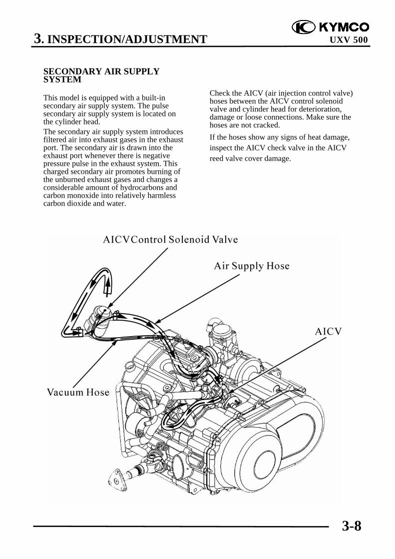
This model is equipped with a built-insecondary air supply system. The pulsesecondary air supply system is located onthe cylinder head.The secondary air supply system introducesfiltered air into exhaust gases in the exhaustport. The secondary air is drawn into theexhaust port whenever there is negativepressure pulse in the exhaust system. Thischarged secondary air promotes burning ofthe unburned exhaust gases and changes aconsiderable amount of hydrocarbons andcarbon monoxide into relatively harmlesscarbon dioxide and water.
Check the AICV (air injection control valve)hoses between the AICV control solenoidvalve and cylinder head for deterioration,damage or loose connections. Make sure thehoses are not cracked.If the hoses show any signs of heat damage,inspect the AICV check valve in the AICVreed valve cover damage.

3. INSPECTION/ADJUSTMENT
3-9
UXV 500
SPARK PLUG
Disconnect the spark plug cap and cleanaround the spark plug.
Remove the spark plug using a equippedspark plug wrench or an equivalent tool.
Inspect or replace as described in themaintenance schedule.
INSPECTION
Remove the carbon deposits from the sparkplug with a small wire brush or a spark plugcleaning machine.
The spark plug should be replacedperiodically. Whenever removing thecarbon deposits, be sure to observe theoperational color of the spark plug'sporcelain tip. This color tells you whether ornot the standard spark plug is suitable foryour type of usage. A normal operatingspark plug should be light brown or tancolor. If the spark plug is very white orglazed appearing, then it has been operatingmuch too hot. This spark plug should bereplaced with the colder plug.
Recommended spark plug: NGK: CR7E
Ignition Coil Cap
Spark Plug
Clean around the spark plug base withcompressed air before removing, and besure that no debris is allowed to enter thecombustion chamber.
*

3. INSPECTION/ADJUSTMENT
3-10
UXV 500
Measure the spark plug gap between thecenter and side electrodes with the feelergauge.If necessary, adjust the gap by bending theside electrode carefully.
Spark plug gap:
0.6-0.7 mm (0.024-0.028 in)
Install the spark plug in the cylinder headand hand tighten, then torque to thespecification.
Torque: 1.2 kgf-m (12 N-m, 8.6 lbf-ft)
Install the spark plug cap.
Install the removed parts in the reverseorder of removal.
0.6~0.7 mm

3. INSPECTION/ADJUSTMENT
3-11
UXV 500
VALVE CLEARANCE
To adjust:
Remove the right floorboard (refer to the“FRAME COVERS” section in the chapter2).Remove the cylinder head cover (refer tothe “CYLINDER HEAD COVERREMOVAL/INSTALLATION” section inthe chapter 8).
Remove the timing hole cap and O-ring.
Remove the recoil starter and O-rings (referto the “STARTER PULLEYREMOVAL/INSPECTION/INSTALLATION” section in the chapter8).
Turn the crankshaft clockwise and align the“T” mark on the flywheel with the indexmark on the right crankcase cover.
The punch marks on the camshaft shouldface upward as shown.
If the punch marks on the camshaft arefacing downward, turn the crankshaftclockwise one full turn (360°) and thepunch marks are facing upward.
Inspect and adjust the valve clearancewhile the engine is cold (Below35°C/95°F).
*
Crankshaft Hole Cap/O-ring
Timing Hole Cap
Punch Marks
“T” Mark

3. INSPECTION/ADJUSTMENT
3-12
UXV 500
Adjust by loosening the valve adjustingscrew lock-nut and turning the adjustingscrew until there is a slight drag on thethickness gauge.
Valve clearance (when cold):IN.: 0.1 mm (0.004 in)EX.: 0.1 mm (0.004 in)
Apply oil to the valve adjusting screw lock-nut threads and seating surface.Hold the adjusting screw and tighten thelock nut.
Special tool:Valve adjusting wrench A120E00036
Torque: 0.9 kgf-m (9 N-m, 6.5 lbf-ft)
After tightening the lock nut, recheck thevalve clearance.
Install the removed parts in the reverseorder of removal.
CARBURETOR IDLE SPEED
Warm up the engine before this operation.Start the engine and connect a tachometer.Turn the throttle stop screw to obtain thespecified idle speed.
Idle Speed: 1500±100 rpm
When the engine misses or run erratic,adjust the pilot screw (refer to the“CARBURETORDISASSEMBLY/INSPECTION/ASSEMBLY” section in the chapter 5).
Throttle Stop Screw
The engine must be warm for accurateidle speed inspection and adjustment.
*
Lock Nut
Wrench Thickness Gauge Valve Adjusting

3. INSPECTION/ADJUSTMENT
3-13
UXV 500
CYLINDER COMPRESSION
Warm up the engine before compressiontest.Remove the spark plug.Insert a compression gauge.Open the throttle valve fully and push thestarter button to test the compression.
Cylinder compression:15 kg/cm² (1500 kPa, 213 psi)
If the compression is low, check for thefollowing:- Leaky valves- Valve clearance too small- Leaking cylinder head gasket- Worn piston rings- Worn piston/cylinderIf the compression is high, it indicates thatcarbon deposits have accumulated on thecombustion chamber and the piston head.
ENGINE OILOIL LEVELPlace the machine on a level place.Warm up the engine for several minutes andstop it.
Check the oil level through the inspectionwindow.The oil level should be between themaximum (H) and minimum (L) marks. Ifthe level is low, add oil to raise it to theproper level.Recommended engine oil:KYMCO 4-stroke oil or equivalent motoroil API service classification: SJViscosity: SAE 5W50
Compression Gauge
Inspection WindowLower Level
Upper Level
Run the engine for 2~3 minutes andcheck the oil level after the engine isstopped for 2~3 minutes.
*
Other viscosities shown in the chart maybe used when the average temperature inyour riding area is within the indicatedrange.
*

3. INSPECTION/ADJUSTMENT
3-14
UXV 500
ENGINE OIL REPLACEMENT ANDOIL FILTER CLEANING
1. Place the machine on a level place.2. Warm up the engine for several minutes
and stop it.3. Place a container under the engine.4. Remove the oil filler cap (1).
5. Remove the oil filter cap (2) to drain theoil.
6. Clean the oil strainer with solvent.Inspect the O-ring and replace ifdamaged. Reinstall the O-ring, oilstrainer, compression spring and oil filtercap. Tighten the oil filter cap tospecification.
Torque: 1.5 kgf-m (15 N-m, 11 lbf-ft)
7. Fill the engine with oil and install the oilfiller cap.
Engine oil capacity At disassembly:
3.6 liter (3.17 lmp qt, 3.82 Us qt) At change:
3 liter (2.64 lmp qt, 3.18 Us qt) After draining and oil filter cartridge
change:3.2 liter (2.82 lmp qt, 3.39 Us qt)
O-ringCompression Spring
Oil Strainer Oil Filter Cap
Be sure no foreign material enters thecrankcase.
*
The engine oil will drain more easilywhile the engine is warm.
*
(1) oil fill cap
(2)

3. INSPECTION/ADJUSTMENT
3-15
UXV 500
ENGINE OIL REPLACEMENT (WITHOR WITHOUT OIL FILTERCARTRIDGE REPLACEMENT)
1. Place the machine on a level place.2. Warm up the engine for several minutes
and stop it.3. Place a container under the engine.4. Remove the oil fill cap (1).
5. Remove the drain plug (2) to drain theoil.
Be sure no foreign material enters thecrankcase.
*
The engine oil will drain more easilywhile the engine is warm.
*
(1) oil fill cap
(2)(2)

3. INSPECTION/ADJUSTMENT
3-16
UXV 500
6. Remove the oil filter cartridge (5) with anoil cartridge wrench.
Special tool:Oil cartridge wrench A120E00061
7. Apply a light coat of clean engine oil tothe O-ring (6) of the new oil filtercartridge.
9. Install the new oil filter cartridge with anoil cartridge wrench, and then tighten itto the specified torque.
Torque: 1 kgf-m (10 N-m, 7.2 lbf-ft)
10. Install right side cover.11. Reinstall the drain plug and tighten the
drain plug to the specified torque.
Torque: 2.5 kgf-m (25 N-m, 18 lbf-ft)
12. Add the specified amount ofrecommended engine oil, and theninstall the engine oil filler cap andtighten it.
Engine oil capacity At disassembly:
3.6 liter (3.17 lmp qt, 3.82 Us qt) At change:
3 liter (2.64 lmp qt, 3.18 Us qt) After draining and oil filter cartridge
change:3.2 liter (2.82 lmp qt, 3.39 Us qt)
Make sure the O-ring is seated properly.*
Be sure no foreign material enters thecrankcase.
*
(5)
3. INSPECTION/ADJUSTMENT
3-17
UXV 500
13. Start the engine and warm it up forseveral minutes. While warming up,check for oil leakage. If oil leakage isfound, turn the engine off immediatelyand check for the cause.
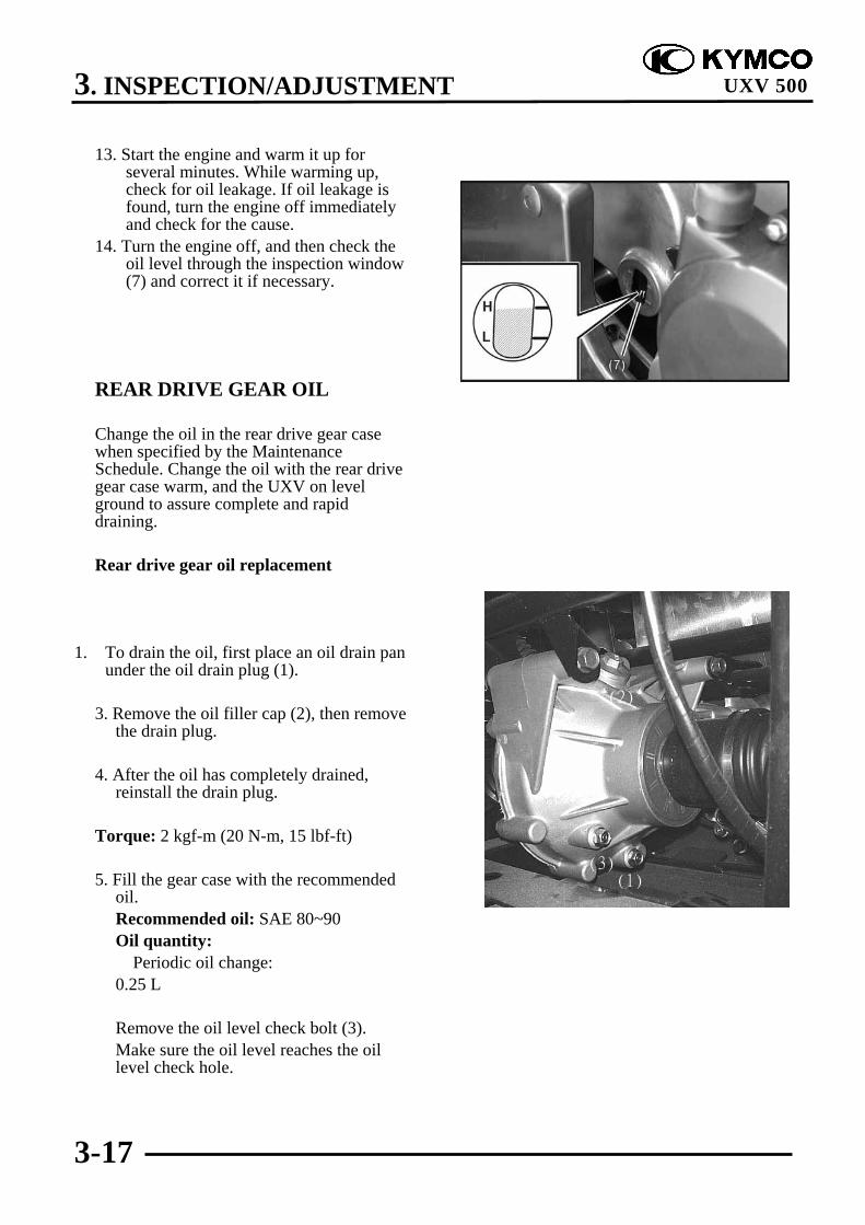
14. Turn the engine off, and then check theoil level through the inspection window(7) and correct it if necessary.
REAR DRIVE GEAR OIL
Change the oil in the rear drive gear casewhen specified by the MaintenanceSchedule. Change the oil with the rear drivegear case warm, and the UXV on levelground to assure complete and rapiddraining.
Rear drive gear oil replacement
1. To drain the oil, first place an oil drain panunder the oil drain plug (1).
3. Remove the oil filler cap (2), then removethe drain plug.
4. After the oil has completely drained,reinstall the drain plug.
Torque: 2 kgf-m (20 N-m, 15 lbf-ft)
5. Fill the gear case with the recommendedoil.Recommended oil: SAE 80~90Oil quantity: Periodic oil change:0.25 L
Remove the oil level check bolt (3).Make sure the oil level reaches the oillevel check hole.
(2)
(3)(1)

3. INSPECTION/ADJUSTMENT
3-18
UXV 500
6. Install the oil filler cap and oil levelcheck bolt.
Torque:Oil filler cap: 1.5 kgf-m (15 N-m, 12 lbf-ft)Oil level check bolt:
2 kgf-m (20 N-m, 15 lbf-ft)
7. Install the skid plate.
FRONT DRIVE GEAR OIL
Change the oil in the front drive gear casewhen specified by the MaintenanceSchedule. Change the oil with the frontdrive gear case warm, and the UXV on levelground to assure complete and rapiddraining.
Front drive gear oil replacement
1. To drain the oil, first place an oil drainpan under the oil drain plug (1).
2. Remove the oil filler bolt (2).
3. Remove the drain plug.
4. After the oil has completely drained,reinstall and tighten the drain plug to thespecified torque.
Torque: 3.2 kgf-m (32 N-m, 23 lbf-ft)
5. Fill the gear case with the recommendedoil.
Recommended oil: SAE 80-90Oil quantity: Periodic oil change:
0.27 L
Be sure no foreign material enters thecrankcase.
*
(2)
3. INSPECTION/ADJUSTMENT
3-19
UXV 500
. Remove the oil level check bolt (3). Makesure the oil level reaches the oil levelcheck hole.
6. Install and tighten the oil filler bolt to the specified torque.
Torque:Oil filler cap:
3.5 kgf-m (35 N-m, 25.5 lbf-ft)Oil level check bolt:
1 kgf-m (10 N-m, 7.2 lbf-ft)
SPARK ARRESTER
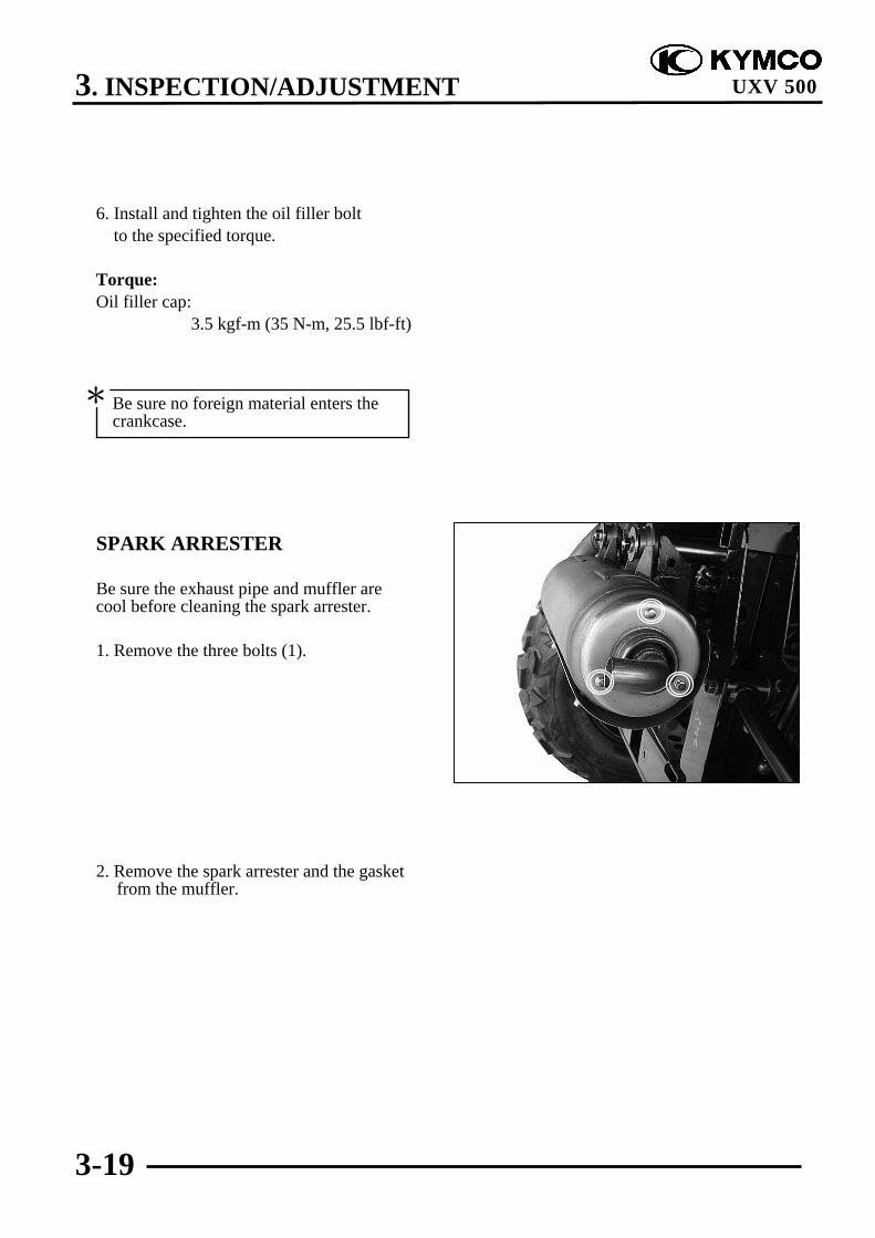
Be sure the exhaust pipe and muffler arecool before cleaning the spark arrester.
1. Remove the three bolts (1).
2. Remove the spark arrester and the gasketfrom the muffler.
Be sure no foreign material enters thecrankcase.
*

3. INSPECTION/ADJUSTMENT
3-20
UXV 500
3. Use a brush to remove carbon depositsfrom the spark arrester screen. Be carefulto avoid damaging the spark arresterscreen. The spark arrester must be free ofbreaks and holes. Replace, if necessary.Check the gasket. Replace, if necessary.
4. Install the spark arrester and the gasket inthe muffler and tighten the three boltssecurely.
DRIVE SHAFT BOOTS
Check the protective boots for holes ortears.If any damage is found, have them replaced.

3. INSPECTION/ADJUSTMENT
3-21
UXV 500
DRIVE BELT
Remove the left crankcase cover (refer tothe “LEFT CRANKCASE COVERREMOVAL/INSTALLATION” section in thechapter 10).
Inspect the drive belt for cracks, scaling,chipping or excessive wear.Measure the V-belt width
Service limit (A): 30.8 mm (1.232 in)
Replace the drive belt if out of specification.
Refer to the “DRIVE PULLEY, DRIVEV-BELT AND DRIVEN PULLEYREMOVAL/INSPECTION/INSTALLATION” section in the chapter10 for removal/installation.
BRAKE PADS INSPECTION
A wear indicator is provided on each brake.The indicators allows checking of brakepads wear. Check the position of theindicator. If the indicator reaches the wearlimit line, to replace the pads.
Drive Belt
(A)

3. INSPECTION/ADJUSTMENT
3-22
UXV 500
BRAKE FLUID INSPECTION
Check if the fluid level is below the lowerlevel mark through the inspection window.
HEADLIGHT AIM
Turn the ignition switch ON and start theengine.Turn on the headlight switch.Adjust the headlight aim by turning theheadlight aim adjusting screws.
Inspection Window
Adjust Screws
(1) Lower level mark(2) Upper level mark

3. INSPECTION/ADJUSTMENT
3-23
UXV 500
STEERING SYSTEMINSPECTION
Place the machine on a level place.Check the steering column bushings andbearings:Turn the steering right and Left,Replace the steering column bushings andor bearings if excessive play
Check the tie-rod endsTurn the handlebar to the left and/or rightuntil it stops completely, then slightly movethe handlebar from left to right.Replace the tie-rod ends if tie-rod end hasany vertical play.
Raise the front end of the machine so thatthere is no weight on the front wheels.Check ball joints and/or wheel bearings.Move the wheels lately back and froth.Replace the front arms and/or wheelbearings if excessive free play.
Tie-rod Ends
3. INSPECTION/ADJUSTMENT
3-24
UXV 500TOE-IN ADJUSTMENT
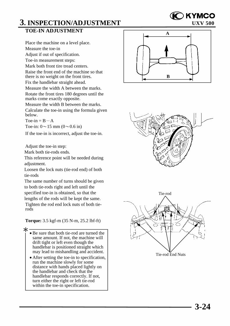
Place the machine on a level place.Measure the toe-inAdjust if out of specification.Toe-in measurement steps:Mark both front tire tread centers.Raise the front end of the machine so thatthere is no weight on the front tires.Fix the handlebar straight ahead.Measure the width A between the marks.Rotate the front tires 180 degrees until themarks come exactly opposite.Measure the width B between the marks.Calculate the toe-in using the formula givenbelow.Toe-in = B-AToe-in: 0~15 mm (0~0.6 in)If the toe-in is incorrect, adjust the toe-in.
Adjust the toe-in step: Mark both tie-rods ends. This reference point will be needed during adjustment. Loosen the lock nuts (tie-rod end) of both tie-rods The same number of turns should be given to both tie-rods right and left until the specified toe-in is obtained, so that the lengths of the rods will be kept the same.
Tighten the rod end lock nuts of both tie-rods
Torque: 3.5 kgf-m (35 N-m, 25.2 lbf-ft)
•Be sure that both tie-rod are turned thesame amount. If not, the machine willdrift tight or left even though thehandlebar is positioned straight whichmay lead to mishandling and accident.
•After setting the toe-in to specification,run the machine slowly for somedistance with hands placed lightly onthe handlebar and check that thehandlebar responds correctly. If not,turn either the right or left tie-rodwithin the toe-in specification.
*
Tie-rod
Tie-rod End Nuts
A
B

3. INSPECTION/ADJUSTMENT
3-25
UXV 500
WHEELS/TIRES
Check the tires for cuts, imbedded nails orother damages.Check the tire pressure.
TIRE PRESSURE
1 Rider
Front 0.7kgf/cm² (10psi)
Rear 0.98 kgf/cm² (14 psi)
TIRE SIZEFront : 25X8-12Rear : 25X10-12
Check the front axle nut for looseness.
Front Axle Nut
Tire pressure should be checked whentires are cold.
*
The threads on both rod-end must be ofthe same length.
*

3. INSPECTION/ADJUSTMENT
3-26
UXV 500
Check the rear axle nut for looseness.If the axle nuts are loose, tighten them to thespecified torque.
Torque:Front: 7 kgf-m (70 N-m, 50 lbf-ft)Rear: 10 kgf-m (100 N-m, 72 lbf-ft)
Inspect the tire surfaces.Replace if wear or damage.
Tire wear limit: 4 mm (0.16 in)
WHEEL INSPECTION
Inspect the wheel.Replace if damage or bendsAlways balance the wheel when a tire orwheel has been changed or replaced.
Rear Axle Nut
•Never attempt even small repairs to thewheel.
•Ride conservatively after installing atire to allow it to seat itself properly onthe rim.
*
It is dangerous to ride with a worn outtire. When a tire wear is out ofspecification, replace the tireimmediately.
*

3. INSPECTION/ADJUSTMENT
3-27
UXV 500
COOLING SYSTEM
COOLANT LEVEL INSPECTION
Place the machine on the level ground.Remove the front hood cover
Check the coolant level in the coolantreservoir when the engine is cold as thecoolant level will vary with enginetemperature. The level should be betweenthe “FULL” (2) and “LOW” (3) levelsurface.If the level is low, remove the reserve tankcap (1) and fill the tank to the “FULL”level line with 1:1 mixture of distilled waterand antifreeze (coolant mixture preparation:refer to the chapter 6 “COOLINGSYSTEM”)
Check to see if there are any coolant leakswhen the coolant level decrease veryrapidly.If reserve tank becomes completely empty,there is a possibility of air getting into thecooling system.Be sure to remove all air from the coolingsystem (refer to the “COOLANTREPLACEMENT” section in the chapter6).
Reinstall the filler cap.
Using coolant with silicate inhibitorsmay cause premature wear of waterpump seals or blockage of radiatorpassages. Using tap water may causeengine damage.
*
(1)
(2)
(3)

3. INSPECTION/ADJUSTMENT
3-28
UXV 500
Check for any coolant leakage from thewater pump, radiator hoses and hose joints.Check the radiator hoses for cracks ordeterioration and replace if necessary.Check that all hose clamps are tight.
Check the radiator air passages for clogs ordamage.Straighten any bent fins, and remove insects,mud or other obstructions with compressedair or low water pressure.Replace the radiator if the air flow isrestricted over more than 20% of theradiating surface.

3. INSPECTION/ADJUSTMENT
3-29
UXV 500
REAR PARKING BRAKEADJUSTMENT
Parking brake adjustment may be required ifthe parking brake does not work properly.Every time the brake pads are replaced,adjust the parking brake.
To adjust:
1. Release the parking brake lever.
2. The rear brake caliper is adjustedautomatically when has more clearancefor the parking brake lever, replace a newpad set also.
Lock the adjuster when the caliper leverapplied.
Parking Brake lever
Lock Nut Adjusting bolt

3. INSPECTION/ADJUSTMENT
3-30
UXV 500
3. Loosen the lock nut and adjuster on thecable.
4. Turn the adjuster until the caliper lever isabout to rotate then Tighten the lock nut.
Parking brake cable end length:L: 53 ± 2 mm (2.12 ± 0.08 in)
5. Slowly turn the adjusting bolt on thecaliper clockwise until resistance is felt,then turn adjusting bolt 1/8counterclockwise.
6. Tighten the lock nut to the specifiedtorque while hold the adjusting bolt.
Torque:1.6 kgf-m (16 N-m, 11.52 lbf-ft)
Adjuster

4. LUBRICATION SYSTEM
4-0
UXV 500
4 __________________________________________________________________________________
__________________________________________________________________________________
__________________________________________________________________________________
__________________________________________________________________________________
__________________________________________________________________________________
LUBRICATION SYSTEM__________________________________________________________________________________
LUBRICATION SYSTEM DIAGRAM --------------------------------- 4- 1SERVICE INFORMATION----------------------------------------------- 4- 2TROUBLESHOOTING---------------------------------------------------- 4- 3LUBRICATION CHECK HOLE ----------------------------------------- 4- 4OIL PUMP REMOVAL/INSPECTION/INSTALLATION----------- 4- 5OIL PUMP DISASSEMBLY/INSPECTION/ASSEMBLY ---------- 4- 9RIGHT CRANKCASE COVER DISASSEMBLY/ASSEMBLY---- 4-12OIL PRESSURE RELIEF VALVE--------------------------------------- 4-14OIL PIPE REMOVAL/INSTALLATION------------------------------- 4-15
4
4. LUBRICATION SYSTEM
4-1
UXV 500
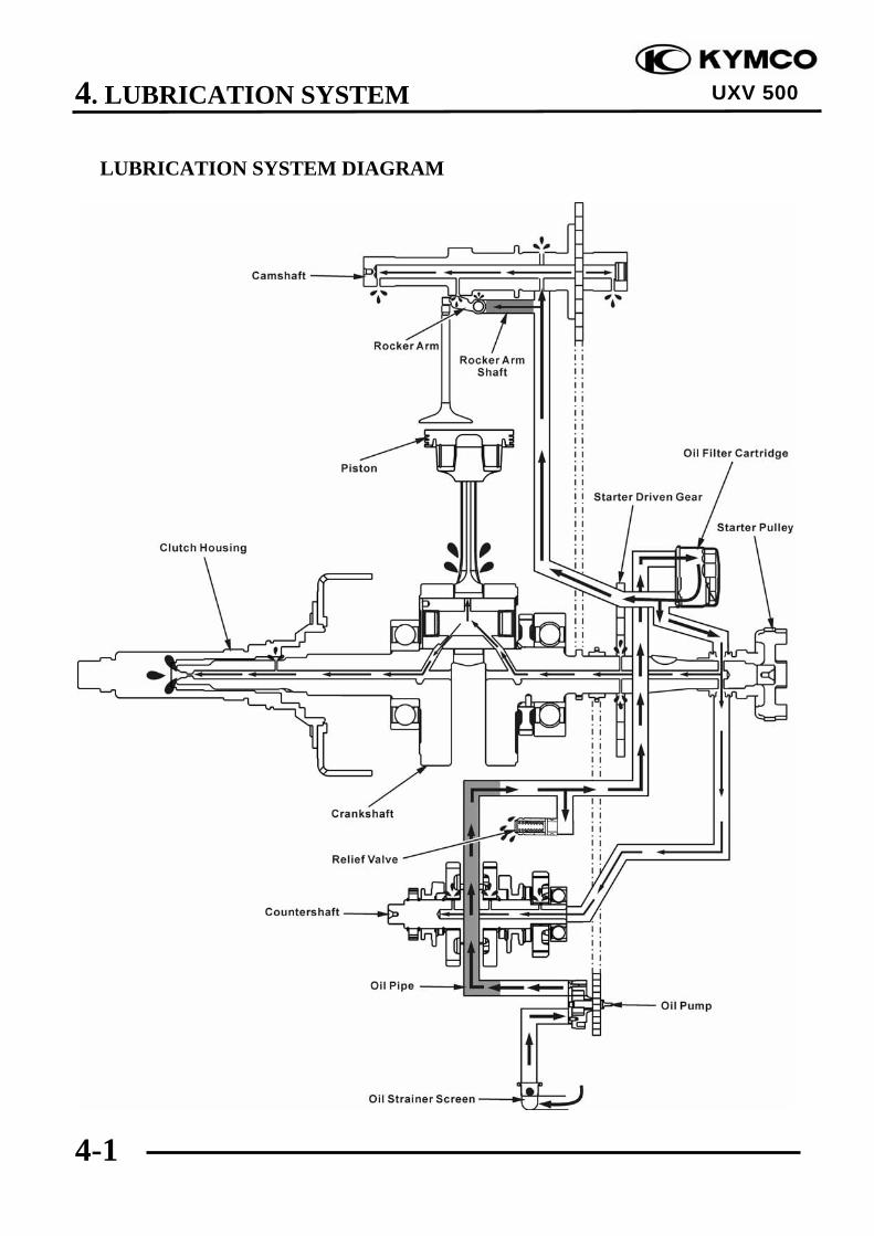
LUBRICATION SYSTEM DIAGRAM

4. LUBRICATION SYSTEM
4-2
UXV 500
SERVICE INFORMATION
GENERAL INSTRUCTIONS• The oil pump service may be done with the engine installed in the frame.• When removing and installing the oil pump use care not to allow dust or dirt to enter the engine.• If any portion of the oil pump is worn beyond the specified service limits, replace the oil pump as
an assembly.• After the engine has been installed check that there are no oil leaks and that oil pressure is
correct.
SPECIFICATIONS Unit: mm (in)
ITEM STANDARD SERVICE LIMITAt draining 3 liter (2.64 lmp qt, 3.18 Us qt) ⎯
At disassembly 3.6 liter (3.17 lmp qt, 3.82 Us qt) ⎯Engine oilcapacity
At draining and oilfilter cartridge change 3.2 liter (2.82 lmp qt, 3.39 Us qt) ⎯
Recommended engine oil
KYMCO 4-stroke oil or equivalentmotor oilAPI service classification SJViscosity: SAE 5W-50
⎯
Tip clearance 0.15 (0.006) max 0.2 (0.008)Body clearance 0.15 – 0.2 (0.006 – 0.008) 0.25 (0.01)Oil pump rotor
Side clearance 0.04 – 0.09 (0.0016 – 0.0036) 0.12 (0.0048)
TORQUE VALUES
Oil pump screw 0.3 kgf-m (3 N-m, 2 lbf-ft)Oil strainer screen cap 1.5 kgf-m (15 N-m, 11 lbf-ft) Apply oil to the threads and seating surface.Oil filter cartridge 1 kgf-m (10 N-m, 7 lbf-ft) Apply oil to the threads and seating surface.Oil pipe bolt 3.5 kgf-m (35 N-m, 25.2 lbf•ft)
Apply oil to the threads and seating surface.
Special tool:Oil seal & bearing drive A120E00014

4. LUBRICATION SYSTEM
4-3
UXV 500
TROUBLESHOOTINGOil level low High oil pressure• Oil consumption • Pressure relief valve stuck closed• External oil leak • Plugged oil filter, gallery, or metering orifice• Worn piston ring • Faulty oil pump• Incorrect piston ring installation• Worn valve guide or seal Seized engine
• No or low oil pressureOil contamination (White appearance) • Clogged oil orifice/passage• From coolant mixing with oil • Internal oil leak Faulty water pump mechanical seal • Non-recommended oil used Faulty head gasket Water leak in crankcase Oil contamination
• Deteriorated oilNo oil pressure • Faulty oil filter• Oil level too low • Worn piston ring (White appearance with water or• Oil pump drive chain broken moisture)• Oil pump drive sprocket broken Damaged water pump mechanical seal• Oil pump damaged (pump shaft) Damaged head gasket• Internal oil leak Oil relief not frequent enough
Low oil pressure• Pressure relief valve stuck open• Clogged oil filter and strainer screen• Oil pump worn or damaged• Internal oil leak• Incorrect oil being used• Oil level too low

4. LUBRICATION SYSTEM
4-4
UXV 500
LUBRICATION CHECK HOLE
Remove the check hole plug/O-ring.Start the engine.Check the oil gushed from the hole. If not,stop the engine immediately and determinethe cause.
Check Hole Plug/O-ring

4. LUBRICATION SYSTEM
4-5
UXV 500
OIL PUMPREMOVAL/INSPECTION/INSTALLATION
REMOVAL
Remove the flywheel and driven gear (referto the “STARTER CLUTCHREMOVAL/INSPECTION/INSTALLATION” section in the chapter 19).
Remove the two bolts and oil pump drivechain guide.
Remove the two bolts and oil separator cover.
Remove snap ring.
Remove the oil pump driven gear, thenremove the oil pump drive chain.
Oil Separator Cover
Oil Pump Drive Chain Guide
Driven Gear
Drive Chain
Snap Ring
When removing and installing the oilpump, use care not to allow dust or dirtto enter the engine..
*
4. LUBRICATION SYSTEM
4-6
UXV 500
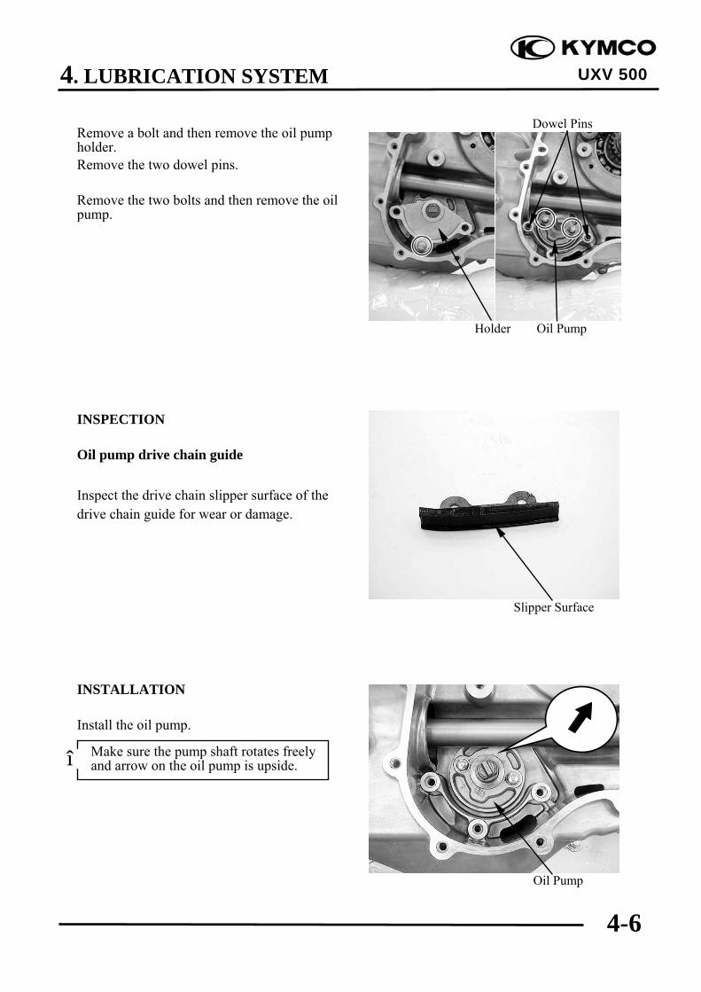
Remove a bolt and then remove the oil pumpholder.Remove the two dowel pins.
Remove the two bolts and then remove the oilpump.
INSPECTION
Oil pump drive chain guide
Inspect the drive chain slipper surface of thedrive chain guide for wear or damage.
INSTALLATION
Install the oil pump.
Holder Oil Pump
Dowel Pins
Slipper Surface
Oil Pump
Make sure the pump shaft rotates freelyand arrow on the oil pump is upside.*

4. LUBRICATION SYSTEM
4-7
UXV 500
Install and tighten the two bolts securely.Install two dowel pins
Install the holder, then install a bolt but donot tighten.
Install the driven gear and drive chain.
Install the snap ring.
Driven Gear
Drive Chain
Snap Ring
Oil Pump Holder
Dowel Pins

4. LUBRICATION SYSTEM
4-8
UXV 500
Install the chain guide, then install andtighten the two bolts securely.
Install the oil separator cover, then install andtighten the three bolts in a crisscross patternin 2 or 3 steps.
Oil Separator Cover
Oil Pump Drive Chain Guide

4. LUBRICATION SYSTEM
4-9
UXV 500
OIL PUMPDISASSEMBLY/INSPECTION/ASSEMBLY
DISASSEMBLY
Remove the oil pump shaft.
Remove the screw and oil pump cover.
Remove the dowel pin, oil pump outer rotorand inner rotor.
Oil Pump Shaft
Outer Rotor
Oil Pump Body Dowel Pin Inner Rotor
Screw
Oil Pump Cover
4. LUBRICATION SYSTEM
4-10
UXV 500
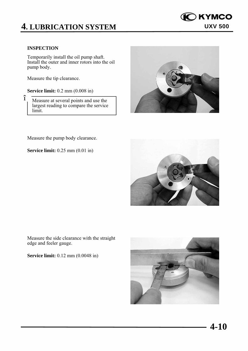
INSPECTION
Temporarily install the oil pump shaft.Install the outer and inner rotors into the oilpump body.
Measure the tip clearance.
Service limit: 0.2 mm (0.008 in)
Measure the pump body clearance.
Service limit: 0.25 mm (0.01 in)
Measure the side clearance with the straightedge and feeler gauge.
Service limit: 0.12 mm (0.0048 in)
Measure at several points and use thelargest reading to compare the servicelimit.
*

4. LUBRICATION SYSTEM
4-11
UXV 500
ASSEMBLY
Dip all parts in clean engine oil.
Install the outer rotor into the oil pump body.Install the inner rotor into the outer rotor.Install the oil pump shaft.Install the dowel pin onto the oil pump body.Install the oil pump cover onto the oil pumpbody by aligning the dowel pin.
Install and tighten the screw to the specifiedtorque.
Torqur: 3 N•m (0.3kgf•m, 2 lbf•ft)
Dowel Pin Oil Pump Cover
Screw
Oil Pump Cover
4. LUBRICATION SYSTEM
4-12
UXV 500
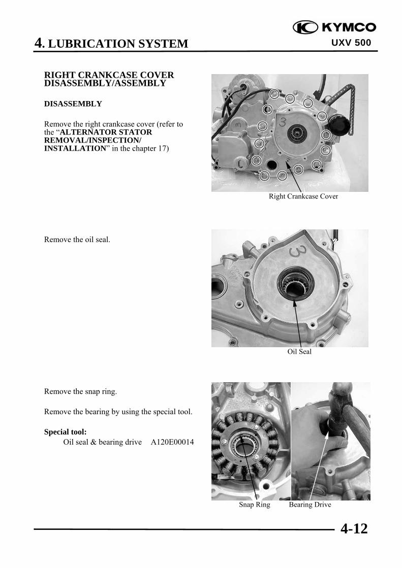
RIGHT CRANKCASE COVERDISASSEMBLY/ASSEMBLY
DISASSEMBLY
Remove the right crankcase cover (refer tothe “ALTERNATOR STATORREMOVAL/INSPECTION/INSTALLATION” in the chapter 17)
Remove the oil seal.
Remove the snap ring.
Remove the bearing by using the special tool.
Special tool:Oil seal & bearing drive A120E00014
Right Crankcase Cover
Snap Ring Bearing Drive
Oil Seal
4. LUBRICATION SYSTEM
4-13
UXV 500
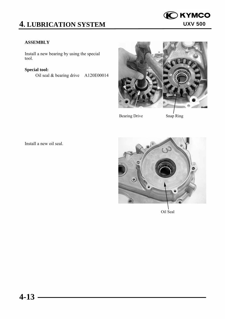
ASSEMBLY
Install a new bearing by using the specialtool.
Special tool:Oil seal & bearing drive A120E00014
Install a new oil seal.
Bearing Drive Snap Ring
Oil Seal

4. LUBRICATION SYSTEM
4-14
UXV 500
OIL PRESSURE RELIEF VALVE
REMOVAL
Remove the right crankcase (refer to the“RIGHT CRANKCASEREMOVAL/INSTALLATION” section inthe chapter 11).
Remove the pressure relief valve and O-ringfrom the right crankcase.
INSPECTION
Check the operation of the pressure reliefvalve by pushing on the piston.
INSTALLATION
Apply oil to a new O-ring and install thepressure relief valve groove, and install therelief valve to the right crankcase.
Oil Pressure Relief Valve
Piston
O-ring
Oil Pressure Relief Valve

4. LUBRICATION SYSTEM
4-15
UXV 500
OIL PIPEREMOVAL/INSTALLATION
REMOVAL
Remove the two bolts, washers (on the oilpipe), oil pipe and washers (under oil pipe).
INSTALLATIION
Install the inner washers on the rightcrankcase.
Install the oil pipe with the thick side faceupward.
Oil Pipe/Washer (under oil pipe)
Oil Pipe
Thick Side
Washers
Bolts/Washers (on the oil pipe)

4. LUBRICATION SYSTEM
4-16
UXV 500
Apply clean engine oil to the bolts, theninstall the outer washers and two bolts.Tighten the two bolts to the specified torque.
Torque: 3.5 kgf-m (35 N-m, 25.2 lbf•ft)
Oil Pipe/Washers (under oil pipe)
Bolts/Washers (on the oil pipe)

5. FUEL SYSTEM
5-0
UXV 500
5 __________________________________________________________________________________
__________________________________________________________________________________
__________________________________________________________________________________
__________________________________________________________________________________
__________________________________________________________________________________
FUEL SYSTEM__________________________________________________________________________________
SERVICE INFORMATION------------------------------------------------ 5- 02TROUBLESHOOTING----------------------------------------------------- 5- 03FUEL TANK ----------------------------------------------------------------- 5- 04CARBURETOR REMOVAL/CHOKE INSPECTION/INSTALLATION-- 5- 05CARBURETOR DISASSEMBLY/INSPECTION/ASSEMBLY ----- 5- 07AIR CLEANER HOUSING ------------------------------------------------ 5- 16PAIR SOLENOID VALVE ------------------------------------------------ 5- 17FUEL FILTER/FUEL PUMP ---------------------------------------------- 5- 18
5
5. FUEL SYSTEM
5-1
UXV 500
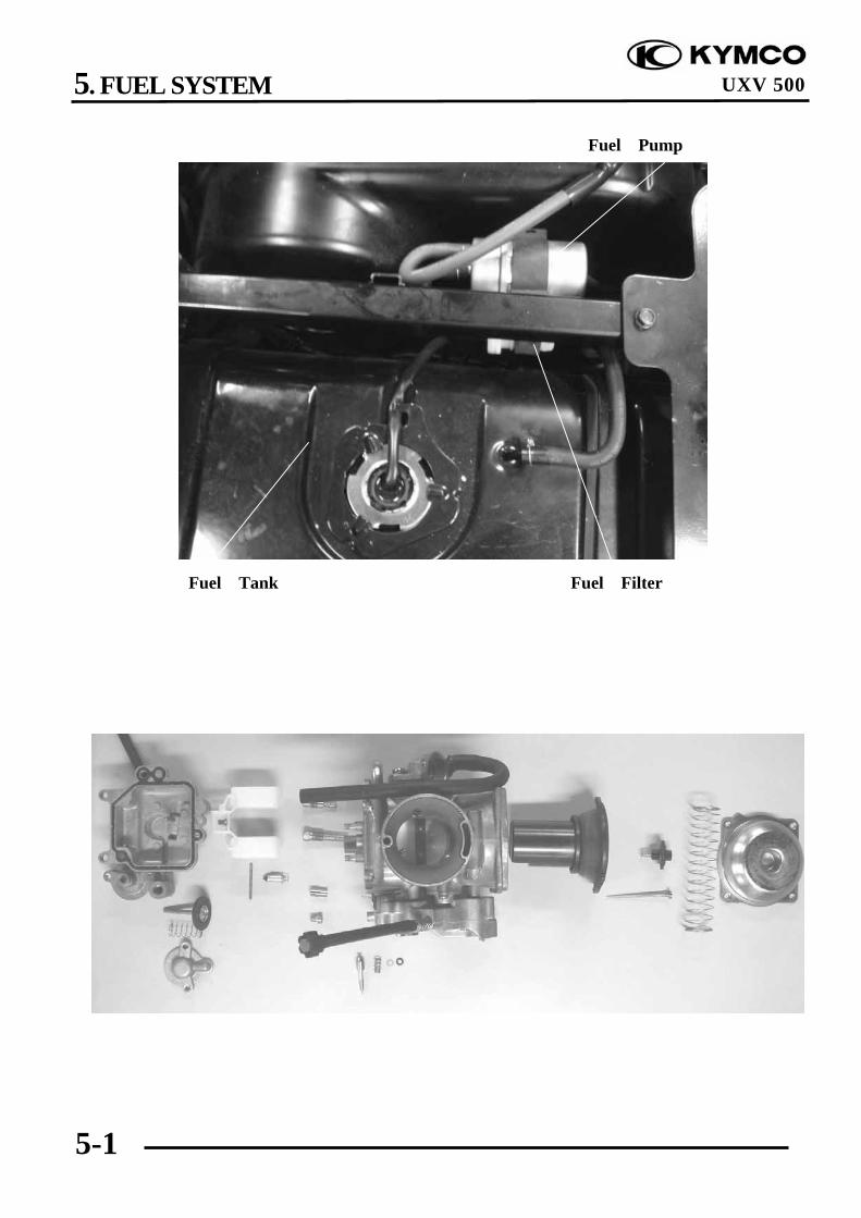
Fuel Pump
Fuel FilterFuel Tank

5. FUEL SYSTEM
5-2
UXV 500 SERVICE INFORMATION GENERAL INSTRUCTIONS
• Do not bend or twist control cables. Damaged control cables will not operate smoothly. • When disassembling fuel system parts, note the locations of O-rings. Replace them with new
ones during reassembly. • Before float chamber disassembly, loosen the drain screw to drain the residual gasoline into a
clean container. • After the carburetor is removed, plug the intake manifold side with a clean shop towel to prevent
foreign matters from entering. • When cleaning the carburetor air and fuel jets, the O-rings and diaphragm must be removed first
to avoid damage. Then, clean with compressed air. • When the machine is not used for over one month, drain the residual gasoline from the float
chamber to avoid erratic idling and clogged slow jet due to deteriorated fuel.
SPECIFICATIONS Item Standard Type CVK Drawing No. LEE8 Bore size φ38 mm Mass of float 7.9±0.2g
ON ROAD #124 Main jet No. OFF ROAD #122
Slow jet No. #40 Choke jet No. --- Idle speed 1500±100 rpm Throttle pedal free play 3~5 mm (0.12~0.2 in) Pilot screw opening 11/2 ±1/2
Gasoline is very dangerous. When working with gasoline, keep sparks and flames away from the working area. Gasoline is extremely flammable and is explosive under certain conditions. Be sure to work in a well-ventilated area.
5. FUEL SYSTEM
5-3
UXV 500
TROUBLESHOOTING
Engine cranks but won’t start Engine lacks power• No fuel in tank • Clogged air cleaner• No fuel to carburetor • Faulty carburetor• Cylinder flooded with fuel • Faulty ignition system• No spark at plug• Clogged air cleaner Lean mixture• Intake air leak • Clogged carburetor fuel jets• Improper throttle operation • Float level too low
• Intake air leakEngine idles roughly, stalls or runs poorly • Clogged fuel tank cap breather hole• Excessively used choke • Kinked or restricted fuel line• Ignition malfunction• Faulty carburetor Rich mixture• Poor quality fuel • Float level too high• Lean or rich mixture • Clogged air jets• Incorrect idle speed • Clogged air cleaner
Misfiring during acceleration• Faulty ignition system• Faulty carburetor
Backfiring at deceleration• Float level too low• Incorrectly adjusted carburetor• Faulty exhaust muffler

5. FUEL SYSTEM
5-4
UXV 500
FUEL TANK
REMOVAL
Key Switch “OFF”.Remove the seat, and center cover. cargo bedUp then remove the fuel cap.Remove the side panel .R.front and protectorFuel tank.Remove the tank frame.
Disconnect the fuel tube from fuel pump.
Disconnect the fuel unit connectors.Remove the 4 screws and from the fuel tank,then remove the fuel tank.
INSTALLATION
Fuel tank installation is in the reverse orderof removal.
Warning• Keep sparks and flames away from the
work area.• Wipe off any spilled gasoline.

5. FUEL SYSTEM
5-5
UXV 500
CARBURETOR REMOVAL/CHOKEINSPECTION/INSTALLATION
REMOVALRemove the center cover screws and centercover .Remove shifting automatic transaxle bolt.Remove the air cleaner housing (refer to the“AIR CLEANER HOUSING” section inthis chapter).
Disconnect the over flow hose.Loosen the carburetor clamp screw, thenremove carburetor from intake pipe.
Remove 2 screws, then remove the throttlevalve cover.Disconnect the throttle cable fromcarburetor.
Remove the choke cable/choke plunger fromcarburetor, then remove the carburetor.
Choke Cable Choke Plunger
Carburetor Clamp Screw
cleaner housing
Throttle Cable
Throttle Valve Cover
5. FUEL SYSTEM
5-6
UXV 500
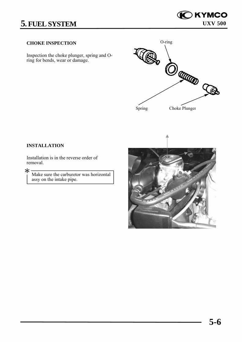
CHOKE INSPECTION
Inspection the choke plunger, spring and O-ring for bends, wear or damage.
INSTALLATION
Installation is in the reverse order ofremoval.
Make sure the carburetor was horizontalassy on the intake pipe.
*
O-ring
Spring Choke Plunger

5. FUEL SYSTEM
5-7
UXV 500
CARBURETORDISASSEMBLY/INSPECTION/ASSEMBLY
DISASSEMBLYRemove the carburetor .
Loosen the drain screw to drain the gasolinefrom the float chamber.
Remove the four screws and top cap
.
Remove the spring and piston valve.
Fuel Drain Plug• Keep sparks and flames away from thework area.
• Drain gasoline into a clean container.• Do not loosen or tighten the painted
bolts and screws of the carburetor.Loosening or tightening them cancause throttle and piston valvesynchronization failure.
*
Spring
Piston Valve
Top Cap

5. FUEL SYSTEM
5-8
UXV 500
Remove the spring retainer, jet needle.
Remove the 3 screws and float chamber.
Pull float pin outs, then remove the float andfloat valve.
Jet Needle Spring Retainer
Piston Valve
Float
Float Pin Float Valve

5. FUEL SYSTEM
5-9
UXV 500
Remove the slow jet.Remove choke jet.Remove main jet.
Remove the needle jet holder.
Remove the needle jet.
Remove the pilot screw, spring, washer andO-ring.
Pilot Screw
Before pilot screw removal, slowly turnthe pilot screw clockwise and count thenumber of turns until the screw islightly seated. Make a note of howmany turns were made so the screw canbe reset correctly.
* Needle Jet
Slow Jet Needle Jet Holder
Main Jet

5. FUEL SYSTEM
5-10
UXV 500
INSPECTION
CARBURETOR BODY/JETS CLEANING
Check carburetor body and each jet for wearor damage.
Clean all jets with a spray-type carburetorcleaner and dry them using compressed air.Clean all circuits of the carburetorthoroughly-not just the perceived problemarea.
Clean the circuits in the carburetor body witha spray-type cleaner and allow each circuit tosoak, if necessary, to loosen dirt and varnish.Blow the body dry using compressed air.
After cleaning, reassemble the carburetorwith new seals.
Some carburetor cleaning chemicals ,especially dip type soaking solutions,are very corrosive and must be handledcarefully. Always follow the chemicalmanufacturer’s instructions on properuse, handling and storage.
Do not use a wire to clean the jets orpassageways. A wire can damage thejets and passageways. If thecomponents cannot be cleaned with aspray cleaner it may be necessary touse a dip-type cleaning solution andallow them to soak. Always follow thechemical manufacturer’s instructionsfor proper use and cleaning of thecarburetor components.
*

5. FUEL SYSTEM
5-11
UXV 500
Check the float and float tang fordeformation or damage.
Check the float valve and valve seat forforeign substance, clogging or damage.Check the tip of the float valve, where itcontacts the valve seat, for stepped wear orcontamination.Check the operation of the float valve.
Check the piston valve for scratches, wearand damage.
Check the rubber diaphragm for tears.
Float Float Tang
Piston Valve
Rubber Diaphragm

5. FUEL SYSTEM
5-12
UXV 500
Check top cap and spring for cracks anddamage.
Check the diaphragms (coasting enrichmentvalve and accelerating pump) for tears.
Check the spring (coasting enrichment valveand accelerating pump) and cover (coastingenricher and accelerating pump) for damage.
Check jet needle, needle jet, slow jet, needlejet holder, main jet, choke jet and pilot screwfor bends, wear and damage.
Top Cap Spring
Spring Covers
Diaphragms Spring
Slow Jet
Jet Needle
Needle Jet
Needle Jet Holder
Main Jet
Pilot Screw
5. FUEL SYSTEM
5-13
UXV 500
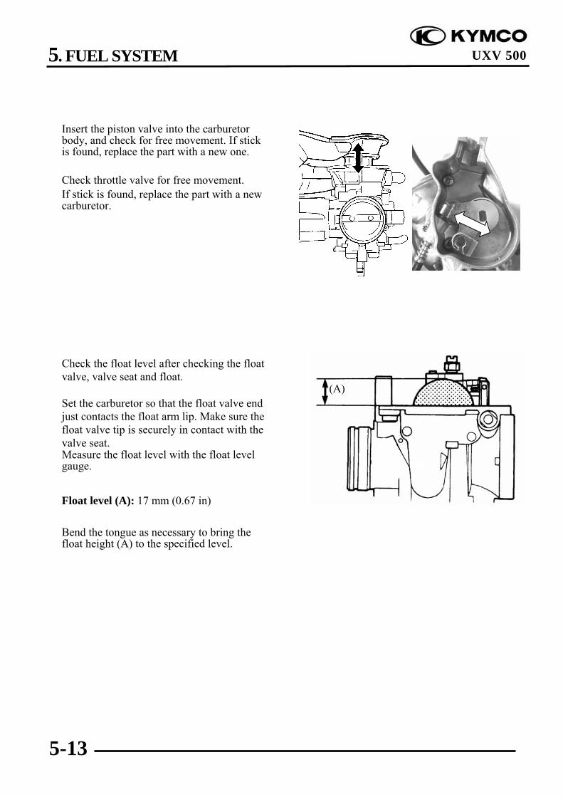
Insert the piston valve into the carburetorbody, and check for free movement. If stickis found, replace the part with a new one.
Check throttle valve for free movement.If stick is found, replace the part with a newcarburetor.
Check the float level after checking the floatvalve, valve seat and float.
Set the carburetor so that the float valve endjust contacts the float arm lip. Make sure thefloat valve tip is securely in contact with thevalve seat.Measure the float level with the float levelgauge.
Float level (A): 17 mm (0.67 in)
Bend the tongue as necessary to bring thefloat height (A) to the specified level.
(A)

5. FUEL SYSTEM
5-14
UXV 500
ASSEMBLY
Carburetor reassembly can be performed inthe reverse order of disassembly. Whenreassembling, carefully observe thefollowing instructions.
(1) Spring(2) Retainer(3) Jet needle(4) Piston valve(5) Cover(6) Spring(7) Casting enrichment valve(8) Choke air in(9) Main jet(10) Needle jet holder(11) Needle jet(12) Slow jet(13) Float valve(14) Float(15) Float pin(16) Pilot screw(17) Cap(18) Cover(19) Float Chamber
Assemble the parts takingconsideration of their function.
Before assembling, wash all of theparts in a clean petroleum basedsolvent.
Replace O-rings and seals with newones.
After cleaning, reinstall the pilot screwto the original setting by turn the screwin until it lightly seats, and thenbacking it out the same number ofturns counted during disassembly.
*
(1)
(2)(3)
(4)
(6)(7) (18)
(8)
(9)(10) (11)(12)
(13)
(15)(14)
(16)
(17)
(5)
(19)

5. FUEL SYSTEM
5-15
UXV 500
Fit a new O-ring in to the float chambergroove securely.
Assemble the accelerating pump diaphragmand new O-ring.
O-ring
Install the accelerating pumpdiaphragm with the small convex facingup.
*
O-ring Small Convex Accelerating Pump Cover
Accelerating Pump Diaphragm

5. FUEL SYSTEM
5-16
UXV 500
AIR CLEANER HOUSING
REMOVAL/INSTALLATION
Remove the seat and center coversLoosen the carburetor-to-air cleanerconnecting tube band screw.
Remove the clip and disconnect thecrankcase breather hose from the crankcase.Remove the mounting bolts and then removethe air cleaner housing from the carburetorand the intake duct.
Installation is in the reverse order ofremoval.
Band Screw
Breather Hose

5. FUEL SYSTEM
5-17
UXV 500
AIR SOLENOID VALVE
REMOVAL/INSTALLATION
Disconnect air supply hose and vacuum hosefrom the air solenoid valve, then remove theair solenoid valve from frame.
Installation is in the reverse order ofremoval.
Vacuum Hose
Air Supply Hose AIR Solenoid Valve

5. FUEL SYSTEM
5-18
UXV 500
FUEL FILTER/FUEL PUMPFUEL FILTER INSPECTION
Visually check the fuel filter. Ifaccumulation of sediment or clogging isfound, replace the fuel filter with a new one.
Install the fuel filter .
FUEL PUMP INSPECTION
Measure resistance between the terminals offuel pump lead wire coupler.If the measurement is out of specificationreplace the fuel pump.Fuel pump resistance: 1-2.5Ω
As shown in the right illustration, connectthe battery to the fuel pump and measure thepump discharge amount per minute usingkerosene.Battery (+) to BR /LBattery (-) to GDischarge amount per minute:370 ml (12.6 US oz, 13 Imp oz)
If the measurement is less than the standardvalue, replace the fuel pump with a new one.
Do not use gasoline in this test as its ishighly combustible.
*
Fuel filter
Fuel pump coupler

5. FUEL SYSTEM
5-19
UXV 500
FUEL PUMPREMOVAL/INSTALLATION
Remove the seat.Disconnect the fuel hoses.Disconnect the fuel pump connector.Remove the fuel pump and filter.Installation is in the reverse order ofremoval.
Install the fuel pump with the arrowmark facing up.
Connect the fuel inlet hose between theinlet duct of the fuel pump and fuelfilter.
Connect the fuel outlet hose betweenthe outlet duct of the fuel pump andcarburetor.
*
Inlet Duct
Outlet Duct
Fuel Pump
Fuel FilterFuel Tank
6. COOLING SYSTEM
6-0
UXV 500
6 __________________________________________________________________________________
__________________________________________________________________________________
__________________________________________________________________________________
__________________________________________________________________________________
__________________________________________________________________________________
COOLING SYSTEM__________________________________________________________________________________
SYSTEM FLOW PATTERN----------------------------------------------- 6- 1SERVICE INFORMATION------------------------------------------------ 6- 2TROUBLESHOOTING----------------------------------------------------- 6- 4COOLING SYSTEM TESTING------------------------------------------- 6- 5COOLANT REPLACEMENT --------------------------------------------- 6- 5THERMOSTAT-------------------------------------------------------------- 6- 8WATER PUMP -------------------------------------------------------------- 6-11RADIATOR ------------------------------------------------------------------ 6-14FAN MOTOR SWITCH ---------------------------------------------------- 6-15
FAN MOTOR ---------------------------------------------------------------- 6-16WATER TEMPERATURE SENSOR ------------------------------------ 6-17RAIDATOR RESERVE TANK ------------------------------------------- 6-18OIL COOLER------------------------------------------------------------------6-19
6

6. COOLING SYSTEM
6-1
UXV 500
SYSTEM FLOW PATTERN

6. COOLING SYSTEM
6-2
UXV 500
SERVICE INFORMATION
GENERAL INSTRUCTIONS
WARING:Removing the radiator cap while the engine is hot can allow the coolant to spray out,seriously scalding you. Always let the engine and radiator cool down before removing theradiator cap.
CAUTION:Radiator coolant is toxic. Keep it away from eyes, mouth, skin and clothes.
• If any coolant gets in your eyes, rinse them with water and consult a physician immediately.• If any coolant in swallowed, induce vomiting, gargle and consult a physician immediately.• If any coolant gets on your skin or clothes, rinse thoroughly with plenty of water.
NOTE:Use coolant with silicate inhibitors may cause premature wear of water pump seals or blockageof radiator passages. Using tap water may cause engine damage.
• This section covers service of the cooling system.• Add coolant at the reserve tank. Do not remove the radiator cap except to refill or drain the
system.• All cooling system services can be done with the engine in the frame.• Avoid spilling coolant on painted surfaces.• After servicing the system, check for leaks with a cooling system tester.
SPECIFICATIONSITEM SPECIFICATIONS
Radiator and engine 2 liter (2.1 US qt, 1.76 lmp qt)Coolant capacity Reserve tank 0.45 liter (0.47 US qt, 0.39 lmp qt)
Radiator cap relief pressure 90 kPa (0.9 kgf/cm2, 12.8 psi)Begin to open 80 - 84°C (176 - 183°F)Fully open 95°C (203°F)ThermostatValve lift 8 mm (0.3 in) minimum
Standard coolant concentration 1:1 mixture with soft water

6. COOLING SYSTEM
6-3
UXV 500
COOLANT GRAVITY CHARTTemp.
Coolantconcentration
0 5 10 15 20 25 30 35 40 45 50
5% 1.009 1.009 1.008 1.008 1.007 1.006 1.005 1.003 1.001 0.009 0.99710% 1.018 1.107 1.017 1.016 1.015 1.014 0.013 1.011 1.009 1.007 1.00515% 1.028 1.027 1.026 1.025 1.024 1.022 1.020 1.018 1.016 1.014 1.01220% 1.036 1.035 1.034 1.033 1.031 1.029 1.027 1.025 1.023 1.021 1.01925% 1.045 1.044 1.043 1.042 1.040 1.038 1.036 1.034 1.031 1.028 1.02530% 1.053 1.051 1.051 1.049 1.047 1.045 1.043 1.041 1.038 1.035 1.03235% 1.063 1.062 1.060 1.058 1.056 1.054 1.052 1.049 1.046 1.043 1.04040% 1.072 1.070 1.068 1.066 1.064 1.062 1.059 1.056 1.053 1.050 1.04745% 1.080 1.078 1.076 1.074 1.072 1.069 1.056 1.063 1.062 1.057 1.05450% 1.086 1.084 1.082 1.080 1.077 1.074 1.071 1.068 1.065 1.062 1.05955% 1.095 1.093 1.091 1.088 1.085 1.082 1.079 1.076 1.073 1.070 1.06760% 1.100 1.098 1.095 1.092 1.089 1.086 1.083 1.080 1.077 1.074 1.071
COOLANT MIXTURE (WITH ANTI-RUST AND ANTI-FREEZING EFFECTS)Freezing Point Mixing Rate KYMCO SIGMA Coolant Concentrate Distilled Water
-9 20% -15 30% 425cc 975cc -25 40% -37 50% -44.5 55%
Cautions for Using Coolant:• Use coolant of specified mixing rate. (The mixing rate of 425cc KYMCO SIGMA coolant
concentrate + 975cc distilled water is 30%.)• Do not mix coolant concentrate of different brands.• Do not drink the coolant which is poisonous.• The freezing point of coolant mixture shall be 5lower than the freezing point of the riding
area.

6. COOLING SYSTEM
6-4
UXV 500
TORQUE VALUES
Water pump cover bolt 1.3 kgf-m (13 N-m, 9 lbf-ft)Fan motor bolt 0.53 kgf-m (5 N-m, 3.8 lbf-ft)Fan motor switch 1.8 kgf-m (17 N-m, 13 lbf-ft)
TROUBLESHOOTING
Engine temperature too high• Faulty radiator cap• Faulty temperature gauge or thermosensor• Air in system• Thermostat stuck closed• Insufficient coolant• Passages blocked in radiator, hoses or water jacket• Faulty cooling fan motor• Faulty fan motor switch• Faulty water pump
Engine temperature too low• Faulty temperature gauge or thermosensor• Thermostat stuck open• Faulty fan motor switch
Coolant leak• Faulty water pump mechanical seal• Deteriorated O-rings• Faulty radiator cap• Damaged or deteriorated cylinder head gasket• Loose hose connection or clamp• Damaged or deteriorated hoses

6. COOLING SYSTEM
6-5
UXV 500
COOLING SYSTEM TESTING
RADIATOR CAP INSPECTION
Remove the radiator cap (refer to the“COOLANT REPLACEMENT” sectionin this chapter).
Pressure test the radiator cap.Replace the radiator cap if it does not holdpressure, or if relief pressure is too high ortoo low.It must hold the specified pressure for atleast six seconds.
Radiator Cap Relief Pressure: 90 kPa (0.9 kg/cm², 12.8 psi)
Pressurize the radiator, engine and hoses,and check for leaks.
Repair or replace components if the systemwill not hold the specified pressure for atleast six seconds.
COOLANT REPLACEMENT
PREPARATION
The effectiveness of coolant decreaseswith the accumulation of rest or if there isa change in the mixing proportion duringusage. Therefore, for best performancechange the coolant regularly as specifiedin he maintenance schedule.
Mix only distilled, low mineral waterwith the antifreeze.
Recommended mixture:1:1 (Distilled water and antifreeze)
Excessive pressure can damage thecooling system components.Do not exceed 105 kPa (1.05 kg/cm²,14.9 psi).
*
Radiator Cap
Cap Tester
Before installing the cap in the tester,wet the sealing surface.
*
Cap Tester
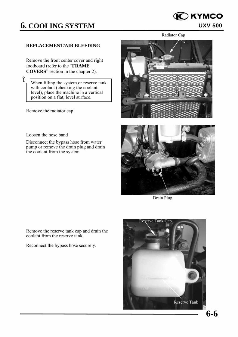
6. COOLING SYSTEM
6-6
UXV 500
REPLACEMENT/AIR BLEEDING
Remove the front center cover and rightfootboard (refer to the “FRAMECOVERS” section in the chapter 2).
Remove the radiator cap.
Loosen the hose bandDisconnect the bypass hose from waterpump or remove the drain plug and drainthe coolant from the system.
Remove the reserve tank cap and drain thecoolant from the reserve tank.
Reconnect the bypass hose securely.
Radiator Cap
When filling the system or reserve tankwith coolant (checking the coolantlevel), place the machine in a verticalposition on a flat, level surface.
*
Reserve Tank Cap
Reserve Tank
Drain Plug

6. COOLING SYSTEM
6-7
UXV 500
Place the machine on a flat, level surface.Fill the reserve tank to the upper level(FULL) line.
Fill the system with the recommendedcoolant through the filler opening up to thefiller neck.
Bleed air from the system as follow:1. Start the engine and let it idle for 2−3
minutes.2. Snap the throttle three to four times to
bleed air from the system.3. Stop the engine and add coolant to the
proper level if necessary. Reinstall theradiator cap.
4. Check the level of coolant in the reservetank and fill to the upper level if it islow.
Filler Neck
Reserve Tank Cap
FULL
LOW

6. COOLING SYSTEM
6-8
UXV 500
THERMOSTAT
REMOVAL
Remove the nut and thermostat housingstay from the frame.
Remove the bolts, housing stay andthermostat housing cover.
Remove the O-ring from the housing cover.Remove the thermostat.
Thermostat
O-ring
Thermostat
Housing stay Thermostat Housing Cover
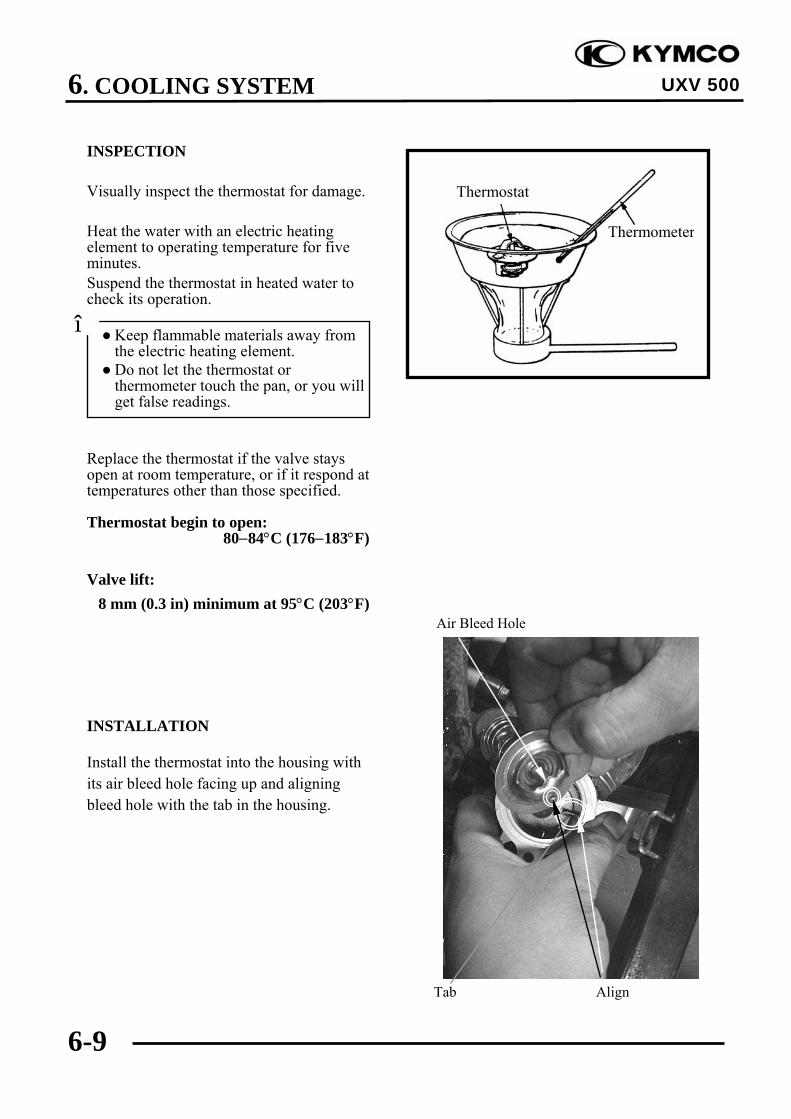
6. COOLING SYSTEM
6-9
UXV 500
INSPECTION
Visually inspect the thermostat for damage.
Heat the water with an electric heatingelement to operating temperature for fiveminutes.Suspend the thermostat in heated water tocheck its operation.
Replace the thermostat if the valve staysopen at room temperature, or if it respond attemperatures other than those specified.
Thermostat begin to open:80−84°C (176−183°F)
Valve lift:8 mm (0.3 in) minimum at 95°C (203°F)
INSTALLATION
Install the thermostat into the housing withits air bleed hole facing up and aligningbleed hole with the tab in the housing.
Thermostat
Thermometer
Keep flammable materials away fromthe electric heating element.
Do not let the thermostat orthermometer touch the pan, or you willget false readings.
*
Tab Align
Air Bleed Hole

6. COOLING SYSTEM
6-10
UXV 500
Install a new O-ring into the housing covergroove.
Install the housing cover and housing stayto the housing.Tighten the bolts securely.
Install the housing stay to the frame.Tighten the nut securely.
Fill the system with recommended coolantand bleed the air (refer to the “COOLANTREPLACEMENT” section in thischapter).
Thermostat
O-ring

6. COOLING SYSTEM
6-11
UXV 500
WATER PUMP
MECHANICAL SEAL INSPECTION
Inspect the coolant leakage.If there is leakage, the mechanical seal isdefective, and water pump body should bereplaced.
REMOVAL
Drain the coolant (refer to the “COOLANTREPLACEMENT” section in thischapter).
Loosen the hose bands and disconnect thelower radiator hoses and bypass hose fromthe water pump.
Remove the four bolts and water pumpcover and O-ring.
Water Pump Cover/O-ring
Water Hose
Bypass Hose

6. COOLING SYSTEM
6-12
UXV 500
Remove the water pump body from thecrankcase.
INSTALLATION
Apply engine oil to a new O-ring and installit onto the stepped portion of the waterpump.
Install the water pump into the crankcasewhile aligning the water pump shaft groovewith oil pump shaft end.
Align the mounting bolt holes in the waterpump and crankcase and make sure thewater pump is securely installed.
Install a new O-ring into the groove in thewater pump cover.
Water Pump Body
Align
O-ring
O-ring

6. COOLING SYSTEM
6-13
UXV 500
Install the water pump cover and tighten thebolts to the specified toque.
Torque: 1.3 kgf-m (13 N-m, 9 lbf-ft)
Connect the water hoses and bypass hose,then tighten the hose bands.
Fill the system with recommended coolantand bleed the air (refer to the “COOLANTREPLACEMENT” section in thischapter).
Water Pump Cover/O-ring Water Hose
Water Hose
Bypass Hose

6. COOLING SYSTEM
6-14
UXV 500
RADIATOR
REMOVAL
Drain the coolant
Remove the front fender (refer to the“FRAME COVERS” section in thechapter 2).
Remove the four mounting bolt from fanguide and then remove fan guide.
Loosen the hose bands and disconnect theradiator lower water hose, water filler hose,bleed hose and upper water hose from theradiator.Disconnect the fan switch connectors.
Remove the two mounting bolts under radiatorand two mounting bolts on the radiator, thenremove radiator.
INSTALLATION
Installation is in the reverse order ofremoval.Fill the system with recommended coolantand bleed the air
Be careful not to damage the radiatorcore.
*
Water Filler Hose Fan Motor SW
Lower Water Hose Bleed Hose Upper Water
Fan Guide

6. COOLING SYSTEM
6-15
UXV 500
FAN MOTOR SWITCH
REMOVAL
Disconnect the fan motor switch connectors(refer to the “RADIATOR” section in thischapter).
Remove the fan motor switch.
INSPECTION
Place the fan motor switch in oil containedin a pan as shown and raise the oiltemperature gradually to check for thetemperature at which the switch starts tooperate.If the switch operating temperature is notwithin the specified range, replace theswitch with a new one.OFF→ON Over 88−92°CON→OFF Lower 88−92°C
INSTALLATION
Fit the O-ring.Tighten the cooling fan motor switch tospecified torque.
Torque: 1.8 kgf-m (17 N-m, 13 lbf-ft)
Fan Motor Switch
O-ring
Handle the cooling fan motor switchcarefully as it is vulnerable to impact.
Do not allow the cooling fan motorswitch ∈and the thermometer ∉tocome in contact with the bottom of thepan.
*
Replace the O-ring a new one. Do not coat grease to the O-ring.
*
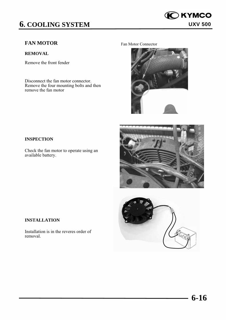
6. COOLING SYSTEM
6-16
UXV 500
FAN MOTOR
REMOVAL
Remove the front fender
Disconnect the fan motor connector.Remove the four mounting bolts and thenremove the fan motor
INSPECTION
Check the fan motor to operate using anavailable battery.
INSTALLATION
Installation is in the reveres order ofremoval.
Fan Motor Connector
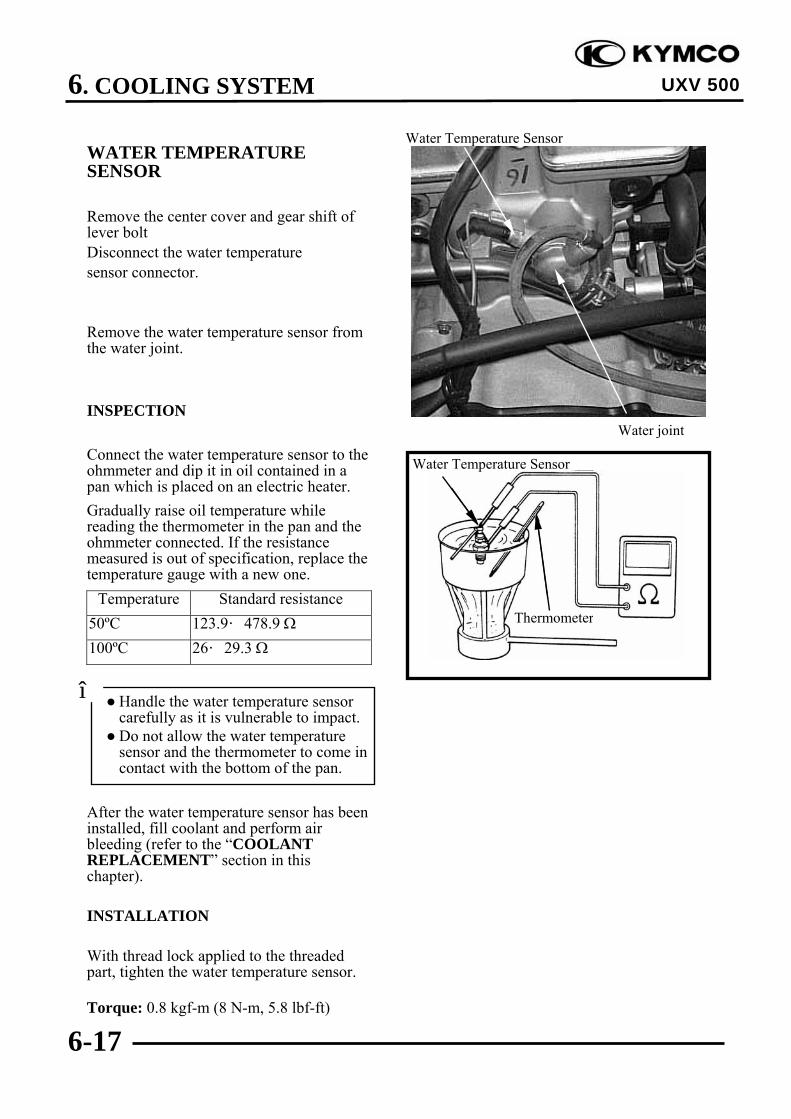
6. COOLING SYSTEM
6-17
UXV 500
WATER TEMPERATURESENSOR
Remove the center cover and gear shift oflever boltDisconnect the water temperaturesensor connector.
Remove the water temperature sensor fromthe water joint.
INSPECTION
Connect the water temperature sensor to theohmmeter and dip it in oil contained in apan which is placed on an electric heater.Gradually raise oil temperature whilereading the thermometer in the pan and theohmmeter connected. If the resistancemeasured is out of specification, replace thetemperature gauge with a new one.
Temperature Standard resistance50ºC 123.9–478.9 Ω100ºC 26–29.3 Ω
After the water temperature sensor has beeninstalled, fill coolant and perform airbleeding (refer to the “COOLANTREPLACEMENT” section in thischapter).
INSTALLATION
With thread lock applied to the threadedpart, tighten the water temperature sensor.
Torque: 0.8 kgf-m (8 N-m, 5.8 lbf-ft)
Water Temperature Sensor
Thermometer
Water joint
Water Temperature Sensor
Handle the water temperature sensorcarefully as it is vulnerable to impact.
Do not allow the water temperaturesensor and the thermometer to come incontact with the bottom of the pan.
*

6. COOLING SYSTEM
6-18
UXV 500
RADIATOR RESERVE TANK
REMOVAL
Remove the front fender .
Remove the two mounting bolts and thenremove the radiator reserve tank fromframe.
Open the reserve tank cap and drain thecoolant from the reserve tank.
Disconnect the siphon hose.
INSTALLATION
Installation is in the reverse order ofremoval.
Pour the recommended coolant to the upperlevel line with the center stand applied
Siphon Hose

6. COOLING SYSTEM
6-19
UXV 500
OIL COOLERREMOVALDrain the engine oil and remove the oil filterCartridge.Drain the coolant from the system.
Loosen the hose bands and disconnect the oilCooler water hose from the cooler.
Remove the oil cooler mounting bolts,Washers, oil cooler and gasket.
INSPECTIONCheck the cooler for damage.
i
Water Hose Oil Hose
Oil cooler/gasket Bolt and washers
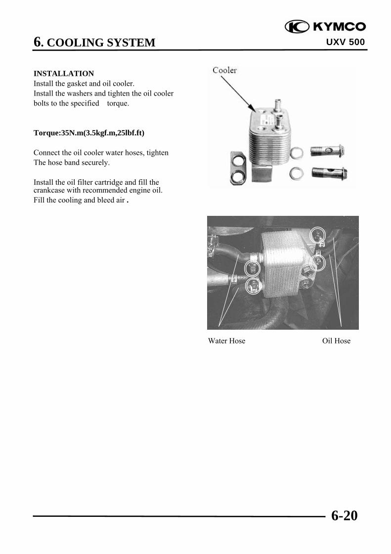
6. COOLING SYSTEM
6-20
UXV 500
INSTALLATIONInstall the gasket and oil cooler.Install the washers and tighten the oil coolerbolts to the specified torque.
Torque:35N.m(3.5kgf.m,25lbf.ft)
Connect the oil cooler water hoses, tightenThe hose band securely.
Install the oil filter cartridge and fill thecrankcase with recommended engine oil.Fill the cooling and bleed air .
Water Hose Oil Hose

7. ENGINE REMOVAL/INSTALLATION
7-0
UXV 500
7 __________________________________________________________________________________
__________________________________________________________________________________
__________________________________________________________________________________
__________________________________________________________________________________
__________________________________________________________________________________
ENGINE REMOVAL__________________________________________________________________________________
SERVICE INFORMATION------------------------------------------------ 7- 1ENGINE REMOVAL ------------------------------------------------------- 7- 2ENGINE INSTALLATION ------------------------------------------------ 7- 8
7

7. ENGINE REMOVAL/INSTALLATION
7-1
UXV 500
SERVICE INFORMATION
GENERAL INSTRUCTIONS• A floor jack or other adjustable support is required to support and maneuver the engine.
Be careful not to damage the machine body, cables and wires during engine removal.• Use shop towels to protect the machine body during engine removal.• The following components require engine removal for serviced with the engine installed in the
frame.™ Oil pump (Chapter 4)™ Water pump (Chapter 6)™ Cylinder head (Chapter 8)™ Cylinder/Piston (Chapter 9)™ Drive and driven pulleys/clutch (Chapter 10)™ Alternator/Starter clutch (Chapter 17 and 19)
• The following components require engine removal for service.™ Transmission (Chapter 11)™ Crankshaft/Crankcase/Balance shaft (Chapter 12)
TORQUE VALUES Engine mounting bolt/nut 6 kgf-m (60 N-m, 43.5 lbf-ft) Engine hanger nut 3.5 kgf-m (35 N-m, 25 lbf-ft) Front propeller shaft bolt 4.5 kgf-m (45 N-m, 32.5 lbf-ft)
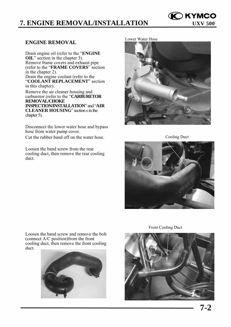
7. ENGINE REMOVAL/INSTALLATION
7-2
UXV 500
ENGINE REMOVAL
Drain engine oil (refer to the “ENGINEOIL” section in the chapter 3).Remove frame covers and exhaust pipe(refer to the “FRAME COVERS” sectionin the chapter 2).Drain the engine coolant (refer to the“COOLANT REPLACEMENT” sectionin this chapter).Remove the air cleaner housing andcarburetor (refer to the “CARBURETORREMOVAL/CHOKEINSPECTION/INSTALLATION” and “AIRCLEANER HOUSING” section s in thechapter 5).
Disconnect the lower water hose and bypasshose from water pump cover.Cut the rubber band off on the water hose.
Loosen the band screw from the rearcooling duct, then remove the rear coolingduct.
Loosen the band screw and remove the bolt(connect A/C position)from the frontcooling duct, then remove the front coolingduct.
Lower Water Hose
Front Cooling Duct
Cooling Duct

7. ENGINE REMOVAL/INSTALLATION
7-3
UXV 500
Disconnect the water hose, bleed hose andwater temperature sensor connectors fromwater joint.
Remove the spark plug cap from cylinderhead.
Remove the bolt from drive select rod.Remove the mounting bolts from the driveselect lever guide, then remove the guideand rod.
Bleed Hose Water Hose
Temperature Sensor Connector
Gear Select Lever Guide Bolt
Spark Plug Cap

7. ENGINE REMOVAL/INSTALLATION
7-4
UXV 500
Disconnect the breather hose from cylinderhead cover
Disconnect the vacuum hose from intakepipe.Slide the rubber sleeve back to expose thestarter motor wire nut.Remove the starter motor cable nut fordisconnect the starter motor cable.Remove the bolt and then disconnect theengine ground cable from starter motor.
Remove the A.C.Generator and ignitionpulse generator connectors.
Breather Hose
A.C. Generator Connector
Ignition Pulse Generator
Rubber Sleeve Engine Ground Cable
Vacuum Hose Starter Cable

7. ENGINE REMOVAL/INSTALLATION
7-5
UXV 500
Disconnect the gear indicator light switchconnector.
Disconnect the speed sensor connector.
Remove the bolts and then remove the frontpropeller shaft from the engine assembly.
Gear Indicator Light Switch Connector
Front Propeller Shaft
Speed Sensor Connector

7. ENGINE REMOVAL/INSTALLATION
7-6
UXV 500
Remove the front lower engine mountingbolt/nut.
Remove the four nuts under right and leftengine hangers, then remove the enginehangers.
Remove the rear lower engine mountingbolt/nut.
Remove the upper engine mountingbolt/nut.
Rise the engine and move the engine thenremove the engine from the frame bydisengaging the rear drive gear case.
Lower Engine Mounting Bolt/Nut
Lower Engine Mounting Bolt/Nut
Upper Engine Mounting Bolt/Nut

7. ENGINE REMOVAL/INSTALLATION
7-7
UXV 500
Tap the rear propeller shaft with rubberhammer and remove the rear propeller shaftfrom the engine assembly.
Rise the engine rear , then move the enginefrom the frame .
Take care not to lose the compressionspring in the rear drive gear case end.
*
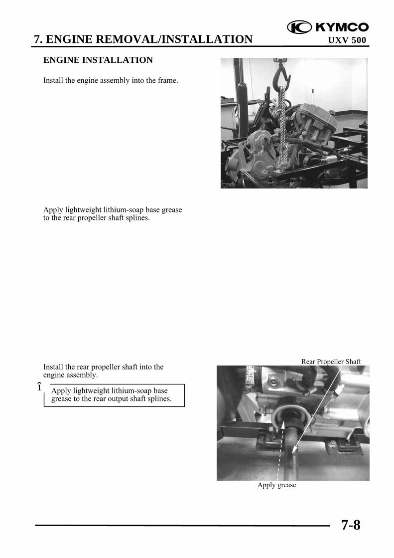
7. ENGINE REMOVAL/INSTALLATION
7-8
UXV 500
ENGINE INSTALLATION
Install the engine assembly into the frame.
Apply lightweight lithium-soap base greaseto the rear propeller shaft splines.
Install the rear propeller shaft into theengine assembly.
Apply lightweight lithium-soap basegrease to the rear output shaft splines.
*
Apply grease
Rear Propeller Shaft

7. ENGINE REMOVAL/INSTALLATION
7-9
UXV 500
Install the compression spring into thepinion gear.
Move the engine rearward and engage therear propeller shaft into the pinion gear.
Install the upper engine mounting bolt andnut loosely.
Install the rear lower engine mounting boltand nut loosely.
Install the engine hangers and four enginehanger nuts loosely.
Install the front lower engine mounting boltand nut loosely.
Tighten the four engine hanger nuts to thespecified torque.
Torque: 3.5 kgf-m (35 N-m, 25 lbf-ft)
Tighten the all engine mounting bolts andnuts to the specified torque.
Torque: 6 kgf-m (60 N-m, 43.5 lbf-ft)
Apply grease Pinion Gear
Compression Spring
Apply lightweight lithium-soap basegrease to the pinion gear splines.
*
Install the joint boot securely.*
Lower Engine Mounting Bolt/Nut
Upper Engine Mounting Bolt/Nut

7. ENGINE REMOVAL/INSTALLATION
7-10
UXV 500
Apply lightweight lithium-soap base greaseto the front propeller shaft splines and frontoutput splines.
Install the front propeller shaft into theengine assembly.
Install the front cooling duct.
Apply grease
Front Propeller Shaft
Make sure the lug on the left crankshaftcase into the cutout on the front coolingduct.
*
Front Cooling Duct

7. ENGINE REMOVAL/INSTALLATION
7-11
UXV 500
Install the rear cooling duct.
Install the removed parts in the reverseorder of removal.
Route the water hoses, wire and cableproperly (refer to the “CABLE &HARNESS ROUTING” section in thechapter 1).
Adjusting the following items: Engine oil (refer to the “ENGINE OIL”
section in the chapter 3). Engine coolant (refer to the “COOLANT
REPLACEMENT” section in thischapter).
Make sure the lug on the left crankshaftcase into the cutout on the rear coolingduct.
*
Cooling Duct

8. CYLINDER HEAD/VALVES
8-0
UXV 500
8 .__________________________________________________________________________________
__________________________________________________________________________________
__________________________________________________________________________________
__________________________________________________________________________________
__________________________________________________________________________________
CYLINDER HEAD/VALVES__________________________________________________________________________________
SCHEMATIC DRAWING ------------------------------------------------- 8- 1SERVICE INFORMATION------------------------------------------------ 8- 2TROUBLESHOOTING----------------------------------------------------- 8- 3CYLINDER COMPRESSION TEST ------------------------------------- 8- 4CYLINDER HEAD COVER REMOVAL/INSTALLATION--------- 8- 5CYLINDER HEAD COVER DISASSEMBLY/ASSEMBLY--------- 8- 6CAMSHAFT REMOVAL/INSPECTION/INSTALLATION --------- 8- 7ROCKER ARMS REMOVAL/INSPECTION/INSTALLATION ---- 8-15CYLINDER HEAD REMOVAL/INSTALLATION-------------------- 8-17CYLINDER HEAD DISASSEMBLY/INSPECTION/ASSEMBLY - 8-24CAM CHAIN REMOVAL/INSPECTION/INSTALLATION -------- 8-28CYYLINDER HEAD BOLTS TIGHTEN TORQUE RECHECK------8-31
8
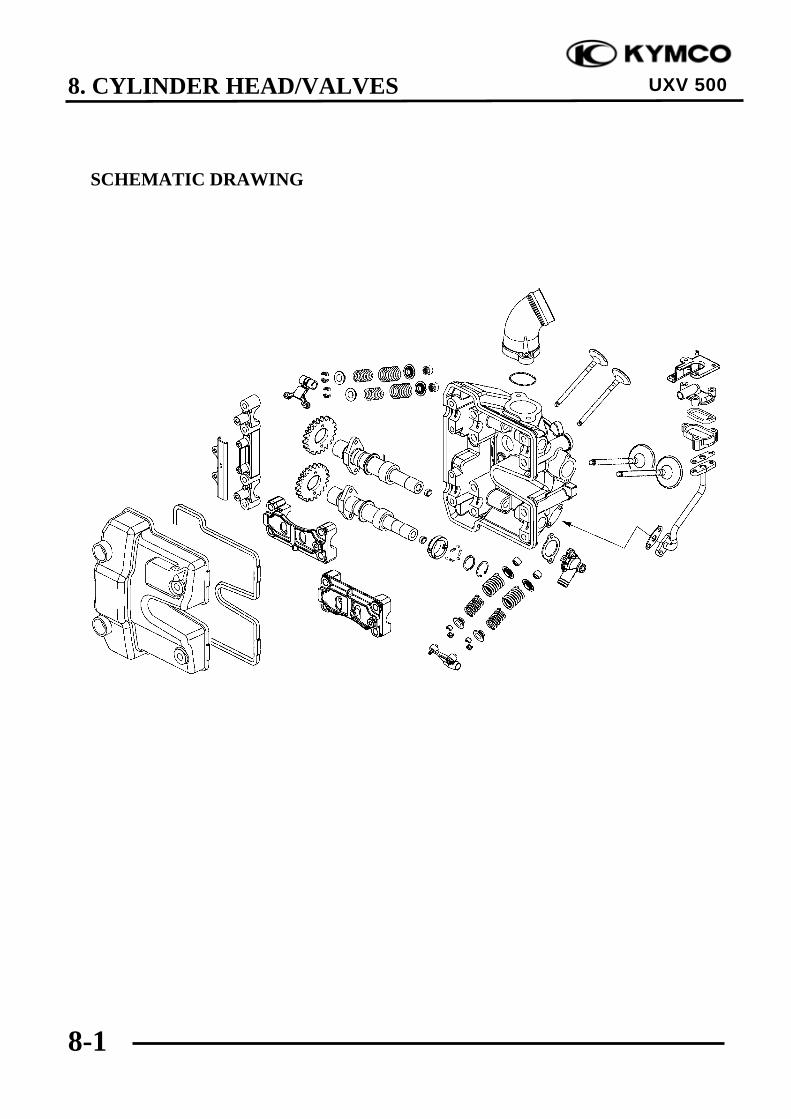
8. CYLINDER HEAD/VALVES
8-1
UXV 500
SCHEMATIC DRAWING
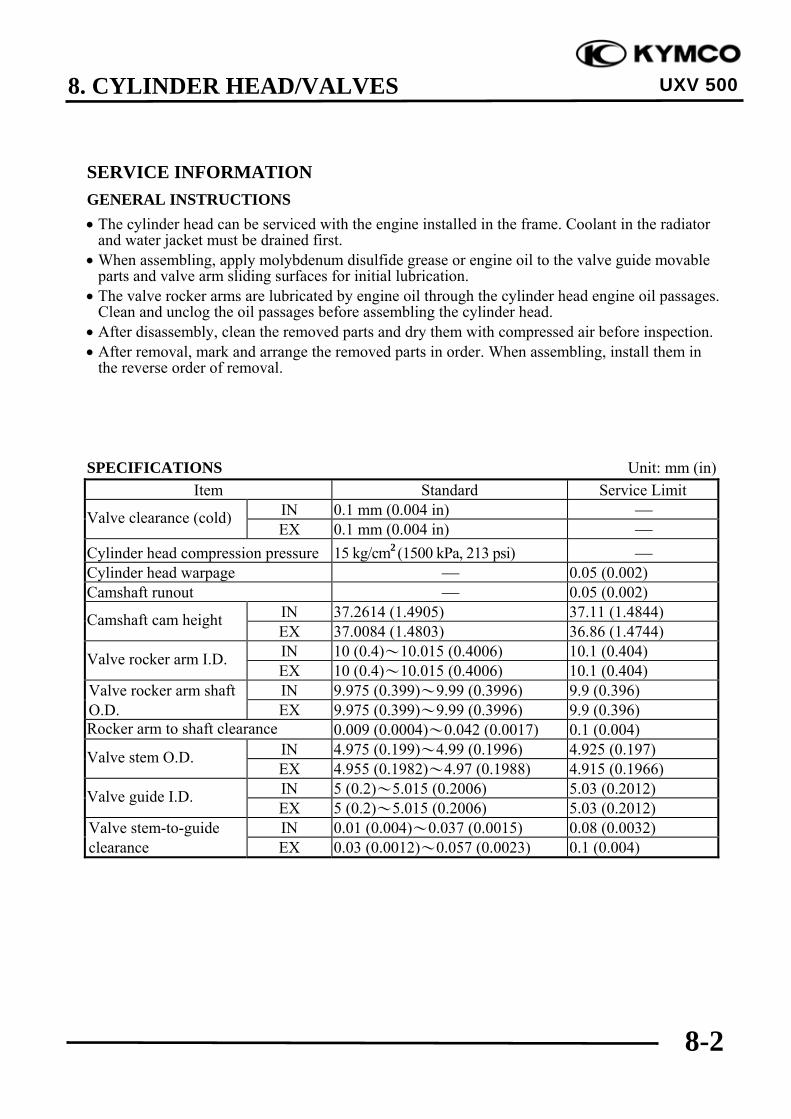
8. CYLINDER HEAD/VALVES
8-2
UXV 500
SERVICE INFORMATIONGENERAL INSTRUCTIONS• The cylinder head can be serviced with the engine installed in the frame. Coolant in the radiator
and water jacket must be drained first.• When assembling, apply molybdenum disulfide grease or engine oil to the valve guide movable
parts and valve arm sliding surfaces for initial lubrication.• The valve rocker arms are lubricated by engine oil through the cylinder head engine oil passages.
Clean and unclog the oil passages before assembling the cylinder head.• After disassembly, clean the removed parts and dry them with compressed air before inspection.• After removal, mark and arrange the removed parts in order. When assembling, install them in
the reverse order of removal.
SPECIFICATIONS Unit: mm (in)Item Standard Service Limit
IN 0.1 mm (0.004 in) ⎯Valve clearance (cold)EX 0.1 mm (0.004 in) ⎯
Cylinder head compression pressure 15 kg/cm2 (1500 kPa, 213 psi) ⎯Cylinder head warpage ⎯ 0.05 (0.002)Camshaft runout ⎯ 0.05 (0.002)
IN 37.2614 (1.4905) 37.11 (1.4844)Camshaft cam heightEX 37.0084 (1.4803) 36.86 (1.4744)IN 10 (0.4)~10.015 (0.4006) 10.1 (0.404)Valve rocker arm I.D.EX 10 (0.4)~10.015 (0.4006) 10.1 (0.404)
Valve rocker arm shaft IN 9.975 (0.399)~9.99 (0.3996) 9.9 (0.396)O.D. EX 9.975 (0.399)~9.99 (0.3996) 9.9 (0.396)Rocker arm to shaft clearance 0.009 (0.0004)~0.042 (0.0017) 0.1 (0.004)
IN 4.975 (0.199)~4.99 (0.1996) 4.925 (0.197)Valve stem O.D.EX 4.955 (0.1982)~4.97 (0.1988) 4.915 (0.1966)IN 5 (0.2)~5.015 (0.2006) 5.03 (0.2012)Valve guide I.D.EX 5 (0.2)~5.015 (0.2006) 5.03 (0.2012)
Valve stem-to-guide IN 0.01 (0.004)~0.037 (0.0015) 0.08 (0.0032)clearance EX 0.03 (0.0012)~0.057 (0.0023) 0.1 (0.004)

8. CYLINDER HEAD/VALVES
8-3
UXV 500
TORQUE VALUESCylinder head bolt (1 – 4) 4.8 kgf-m (48 N-m, 35 lbf-ft) Apply engine oil to threadsCylinder head bolt (5 – 13) 2.3 kgf-m (23 N-m, 17 lbf-ft) Apply engine oil to threadsCylinder head nut 1 kgf-m (10 N-m, 7 lbf-ft)Cylinder head cover bolt 1 kgf-m (10 N-m, 7.2 lbf-ft)Breather separator bolt 1.3 kgf-m (13 N-m, 9 lbf-ft)Cam chain tensioner bolt 1.2 kgf-m (12 N-m, 8.6 lbf-ft)Tensioner sealing bolt 1 kgf-m (10 N-m, 7 lbf-ft)Rocker arm shaft 4.5 kgf-m (45 N-m, 32 lbf-ft)Cam chain guide pivot bolt 2 kgf-m (20 N-m, 15 lbf-ft)Water joint bolt 1.2 kgf-m (12 N-m, 8.6 lbf-ft)
SPECIAL TOOLSValve spring compressor A120E00040
TROUBLESHOOTING• The poor cylinder head operation can be diagnosed by a compression test or by tracing engine
top-end noises.
Poor performance at idle speed White smoke from exhaust muffler• Compression too low • Worn valve stem or valve guide
• Damaged valve stem oil sealCompression too low• Incorrect valve clearance adjustment Abnormal noise• Burned or bend valves • Incorrect valve clearance adjustment• Incorrect valve timing • Sticking valve or broken valve spring• Broken valve spring • Damaged or worn camshaft• Poor valve and seat contact • Worn cam chain tensioner• Leaking cylinder head gasket • Worn camshaft and rocker arm• Warped or cracked cylinder head• Poorly installed spark plug
Compression too high• Excessive carbon build-up in combustion
chamber

8. CYLINDER HEAD/VALVES
8-4
UXV 500
CYLINDER COMPRESSION TEST
Warm up the engine to normal operatingtemperature.Stop the engine and remove the spark plugcap and remove the spark plug (refer to the“SPARK PLUG” section in the chapter 3).
Install a compression gauge into the sparkplug hole.
Open the throttle all the way and crank theengine with the starter motor until the gaugereading stops rising.The maximum reading is usually reached 4 –7 seconds.
Compression pressure:15 kg/cm2 (1500 kPa, 213 psi)
Low compression can be caused by: Blown cylinder head gasket Improper valve adjustment Valve leakage Worn piston ring or cylinder
High compression can be caused by: Carbon deposits in combustion chamber oron piston head
Spark Plug Cap
Compression Gauge
To avoid discharging the battery, do notoperate the starter motor for more thanseven seconds.
*
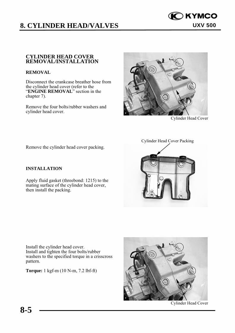
8. CYLINDER HEAD/VALVES
8-5
UXV 500
CYLINDER HEAD COVERREMOVAL/INSTALLATION
REMOVAL
Disconnect the crankcase breather hose fromthe cylinder head cover (refer to the“ENGINE REMOVAL” section in thechapter 7).
Remove the four bolts/rubber washers andcylinder head cover.
Remove the cylinder head cover packing.
INSTALLATION
Apply fluid gasket (threebond: 1215) to themating surface of the cylinder head cover,then install the packing.
Install the cylinder head cover.Install and tighten the four bolts/rubberwashers to the specified torque in a crisscrosspattern.
Torque: 1 kgf-m (10 N-m, 7.2 lbf-ft)
Cylinder Head Cover
Cylinder Head Cover Packing
Cylinder Head Cover

8. CYLINDER HEAD/VALVES
8-6
UXV 500
CYLINDER HEAD COVERDISASSEMBLY/ASSEMBLY
DISASSEMBLY
Remove the three bolts and breatherseparator.
Remove the gasket.
ASSEMBLY
Assembly is in the reverse order ofdisassembly.
Torque:Breather separator bolt:
1.3 kgf-m (13 N-m, 9 lbf-ft)
Gasket

8. CYLINDER HEAD/VALVES
8-7
UXV 500
CAMSHAFTREMOVAL/INSPECTION/INSTALLATION
REMOVAL
Remove the cylinder head cover (refer to the“CYLINDER HEAD COVERREMOVAL/INSTALLATION” section inthis chapter).Turn the crankshaft clockwise and align the“T” mark on the flywheel with the indexmark on the right crankcase cover (refer tothe “VALVE CLEARANCE”section in thechapter 3).
Remove the cam chain tensioner lifter sealingbolt, spring and sealing washer.
Remove the two bolts, cam chain tensionerand gasket.
Remove the two bolts and cam chain guide.
Bolt Washer
Spring
Cam Chain Tensioner/Gasket
Cam Chain Guide
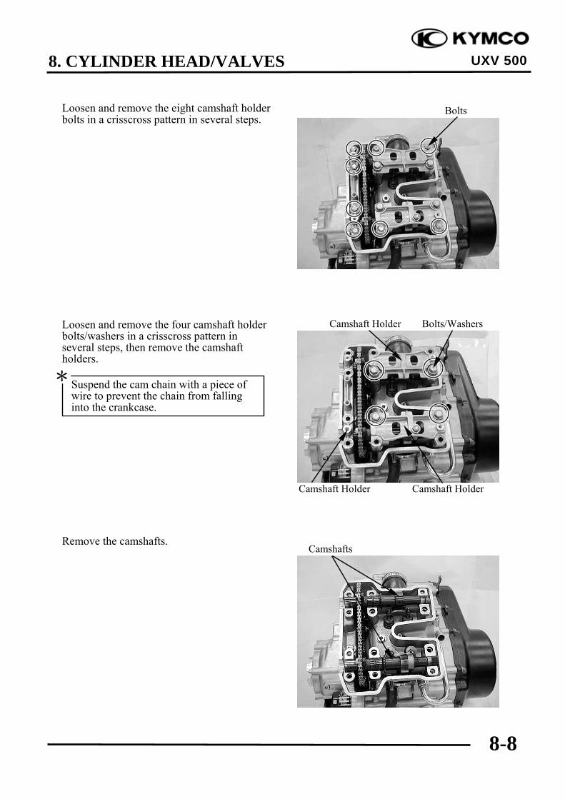
8. CYLINDER HEAD/VALVES
8-8
UXV 500
Loosen and remove the eight camshaft holderbolts in a crisscross pattern in several steps.
Loosen and remove the four camshaft holderbolts/washers in a crisscross pattern inseveral steps, then remove the camshaftholders.
Remove the camshafts.
Bolts
Camshaft Holder Camshaft Holder
Camshaft Holder Bolts/Washers
Camshafts
Suspend the cam chain with a piece ofwire to prevent the chain from fallinginto the crankcase.
*

8. CYLINDER HEAD/VALVES
8-9
UXV 500
INSPECTION
Cam chain guideInspect the cam chain slipper surface of thecam chain guide for wear or damage.
Camshaft holder
Inspect the camshaft surface of each camshaftholder for scoring, scratches, or evidence ofinsufficient lubrication.
Check the stop pin spring on the exhaustcamshaft holder for damage.Replace the stop pin assembly with a new oneif the spring is damage.
Cam Chain Slipper
Stop Pin
Camshaft Holders
Always replace the camshaft holder andcylinder head in pairs
*

8. CYLINDER HEAD/VALVES
8-10
UXV 500
Camshaft
Support both ends of the camshaft with V-blocks and check the camshaft runout with adial gauge.
Service limit: 0.05 mm (0.002 in)
Inspect camshaft lobes forpitting/scratches/blue discoloration.
Measure the cam lobe height.
Service Limits: IN : 37.11 mm (1.4844 in) EX: 36.86 mm (1.4744 in) If any defects are found, replace the camshaftwith a new one, then inspect lubricationsystem.
Check the decompression system by turningthe decompressor cam on the exhaustcamshaft.You should be able to turn the decompressorcam clockwise smoothly, but thedecompressor should not turncounterclockwise.

8. CYLINDER HEAD/VALVES
8-11
UXV 500
Cam chain tensioner
Check the one-way cam operation (tensioner)Unsmooth operation → Replace.
INSTALLATION
Turn the crankshaft clockwise, align the “T”mark on the flywheel with the index mark onthe right crankcase cover (refer to the“VALVE CLEARANCE” in chapter 3).
Apply molybdenum disulfide and oil to thecamshaft journals of the camshaft holder.
Apply molybdenum disulfide and oil to thecamshaft journals of the cylinder head.

8. CYLINDER HEAD/VALVES
8-12
UXV 500
Install the cam chain over the cam sprocketsand then install the intake and exhaustcamshafts.
Install intake and exhaust camshaft holders tothe correct locations.
NOTE: Install the camshafts. a point forattention.
Apply molybdenum disulfide and oil to thecamshaft holes as picture.Install the camshafts, then inject in the holesonto the camshafts with oil until the oiloverflowed.
Timing Marks
Punch Marks
Install each camshafts to the correctlocations.“IN”: no decompressor cam“EX”: has a decompressor cam Make sure the timing marks on the camsprockets are flush with the cylinderhead upper surface and punch marksface upward as shown.
*
Exhaust Camshaft Holder Stop Pin
Install each camshaft holders to thecorrect locations.“IN”: no stop pin.“EX”: has a stop pin.
*
Apply molybdenum disulfide and oil tothe camshaft journals of the camshaftholder.
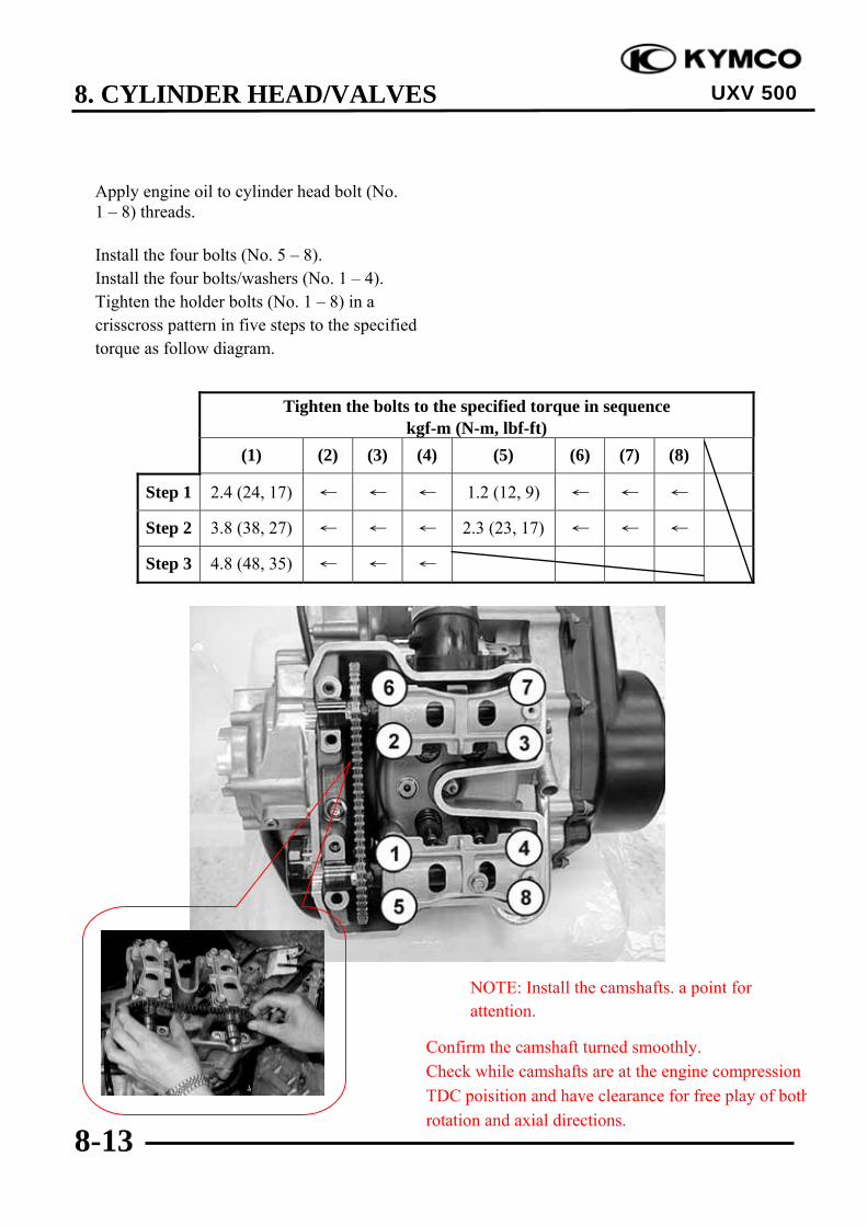
8. CYLINDER HEAD/VALVES
8-13
UXV 500
Apply engine oil to cylinder head bolt (No.1 – 8) threads.
Install the four bolts (No. 5 – 8).Install the four bolts/washers (No. 1 – 4).Tighten the holder bolts (No. 1 – 8) in acrisscross pattern in five steps to the specifiedtorque as follow diagram.
NOTE: Install the camshafts. a point forattention.
Tighten the bolts to the specified torque in sequencekgf-m (N-m, lbf-ft)
(1) (2) (3) (4) (5) (6) (7) (8)
Step 1 2.4 (24, 17) ← ← ← 1.2 (12, 9) ← ← ←
Step 2 3.8 (38, 27) ← ← ← 2.3 (23, 17) ← ← ←
Step 3 4.8 (48, 35) ← ← ←
Confirm the camshaft turned smoothly.Check while camshafts are at the engine compressionTDC poisition and have clearance for free play of bothrotation and axial directions.

8. CYLINDER HEAD/VALVES
8-14
UXV 500
Apply engine oil to cylinder head bolt (No.10 – 13) threads.
Install the common camshaft holder by arrowmark facing outside.
Install and tighten the holder bolts (No. 10 –13) in a crisscross pattern in five steps to thespecified torque as follow diagram.
Tighten the bolts to the specified torque in sequencekgf-m (N-m, lbf-ft)
(10) (11) (12) (13)
Step 4 1.2 (12, 9) ← ← ←
Step 5 2.3 (23, 17) ← ← ←
“Arrow” Mark
Confirm the camshaft turned smoothly.Check while camshafts are at the enginecompression TDC poisition and have clearance forfree play of both rotation and axial directions.

8. CYLINDER HEAD/VALVES
8-15
UXV 500
ROCKER ARMSREMOVAL/INSPECTION/INSTALLATION
REMOVAL
Remove the camshafts (refer to the“CAMSHAFT REMOVAL/INSPECTION/INSTALLATION” section in this chapter).
Remove the rocker arm shafts and washers,then remove the rocker arms.
INSPECTION
Rocker arm shaft
Inspect the rocker arm shaft for bluediscoloration or grooves.If any defects are found, replace the rockerarm shaft with a new one, then inspectlubrication system.
Measure each rocker arm shaft O.D.Measure the I.D. of each rocker arm.Measure arm to shaft clearance.Replace as a set if out of specification.
Service limits: 0.1 mm (0.004 in)
Inspect the rocker arm bore, cam lobe contactsurface and adjuster surface forwear/pitting/scratches/blue discoloration.If any defects are found, replace the rockerarm shaft with a new one, then inspectlubrication system.
Measure each rocker arm shaft O.D.Measure the I.D. of each rocker arm.Measure arm to shaft clearance.Replace as a set if out of specification.
Service limits: 0.1 mm (0.004 in)
Rocker Arm Shaft
Rocker Arm Shafts/Washers
Rocker Arms
Rock Arm
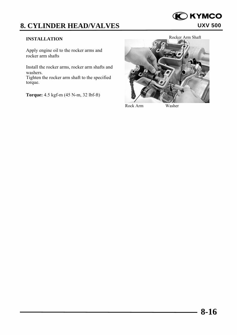
8. CYLINDER HEAD/VALVES
8-16
UXV 500
INSTALLATION
Apply engine oil to the rocker arms androcker arm shafts
Install the rocker arms, rocker arm shafts andwashers.Tighten the rocker arm shaft to the specifiedtorque.
Torque: 4.5 kgf-m (45 N-m, 32 lbf-ft)
Rock Arm Washer
Rocker Arm Shaft

8. CYLINDER HEAD/VALVES
8-17
UXV 500
CYLINDER HEADREMOVAL/INSTALLATION
Remove the camshafts (refer to the“CAMSHAFT REMOVAL/INSPECTION/INSTALLATION” section in this chapter)
Remove the two bolts and intake pipe.
Remove the five bolts, then remove the pairreed valve cover and holder.Remove the two nuts, then remove the pairreed valve and gasket.
Remove the two bolts, water joint, gasket andwater stop collar.
Pair Reed Valve Cover/Holder Gasket
Intake Pipe
Water Joint/Gasket/Water Stop Collar
Always replace the camshaft holder andcylinder head in pairs
*

8. CYLINDER HEAD/VALVES
8-18
UXV 500
Remove the two nuts under the cylinder head.
Remove the bolt and then remove thecylinder head.
Remove the dowel pins and gasket.
Gasket
Dowel Pins

8. CYLINDER HEAD/VALVES
8-19
UXV 500
INSTALLATION
Install the dowel pins and new gasket asshown.
Install the cylinder head.
Apply engine oil to the cylinder head bolt (9)threads.Install the bolt (9) but do not tighten it.
Install the camshafts, intake camshaft holderand exhaust camshaft holder (refer to the“CAMSHAFT REMOVAL/INSPECTION/INSTALLATION” section in this chapter).
Gasket
Dowel Pins
Exhaust Camshaft Holder
Camshafts Intake Camshaft Holder
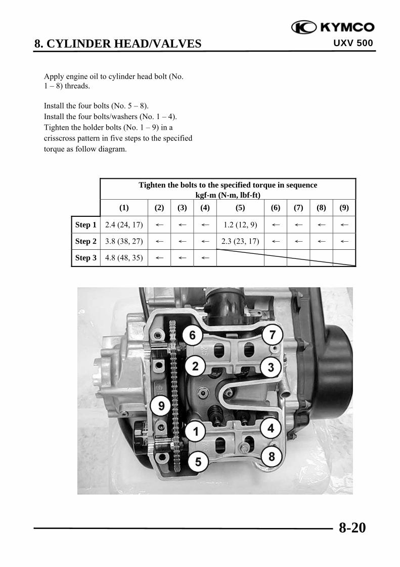
8. CYLINDER HEAD/VALVES
8-20
UXV 500
Apply engine oil to cylinder head bolt (No.1 – 8) threads.
Install the four bolts (No. 5 – 8).Install the four bolts/washers (No. 1 – 4).Tighten the holder bolts (No. 1 – 9) in acrisscross pattern in five steps to the specifiedtorque as follow diagram.
Tighten the bolts to the specified torque in sequencekgf-m (N-m, lbf-ft)
(1) (2) (3) (4) (5) (6) (7) (8) (9)
Step 1 2.4 (24, 17) ← ← ← 1.2 (12, 9) ← ← ← ←
Step 2 3.8 (38, 27) ← ← ← 2.3 (23, 17) ← ← ← ←
Step 3 4.8 (48, 35) ← ← ←
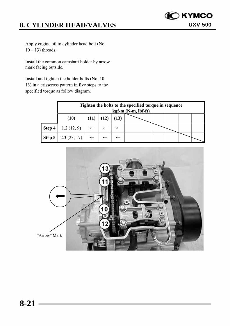
8. CYLINDER HEAD/VALVES
8-21
UXV 500
Apply engine oil to cylinder head bolt (No.10 – 13) threads.
Install the common camshaft holder by arrowmark facing outside.
Install and tighten the holder bolts (No. 10 –13) in a crisscross pattern in five steps to thespecified torque as follow diagram.
“Arrow” Mark
Tighten the bolts to the specified torque in sequencekgf-m (N-m, lbf-ft)
(10) (11) (12) (13)
Step 4 1.2 (12, 9) ← ← ←
Step 5 2.3 (23, 17) ← ← ←

8. CYLINDER HEAD/VALVES
8-22
UXV 500
Install and tighten the two nuts under thecylinder head to the specified torque.
Torque: 1 kgf-m (10 N-m, 7 lbf-ft)
Install the water stop collar, gasket and waterjoint.Install and tighten the two bolts to thespecified torque.
Torque: 1.2 kgf-m (12 N-m, 8.6 lbf-ft)
Install gasket and pair reed valve.Install and tighten the five bolts and two nutsecurely.
Pair Reed Valve Cover/Holder Gasket
Water Joint/Gasket/Water Stop Collar
Bolts

8. CYLINDER HEAD/VALVES
8-23
UXV 500
Install the new O-ring onto the intake pipe.
Install the intake pipe and tighten the twobolts securely.
O-ring
Intake Pipe

8. CYLINDER HEAD/VALVES
8-24
UXV 500
CYLINDER HEADDISASSEMBLY/INSPECTION/ASSEMBLY
Remove the cylinder head (refer to the“CYLINDER HEADREMOVAL/INSTALLATION” section inthis chapter).Remove the valve spring cotters, retainers,springs, spring seats, oil seals and valvesusing a valve spring compressor.
Special tool:Valve Spring Compressor A120E00040
•Be sure to compress the valve springswith a valve spring compressor.
•Mark all disassembled parts to ensurecorrect reassembly.
*
Valve Spring Compressor
Springs Spring Seats Oil Seals
Valve Spring Cotters Retainers Valves

8. CYLINDER HEAD/VALVES
8-25
UXV 500
INSPECTION
Valve /Valve guide
Inspect each valve for bending, burning,scratches or abnormal stem wear.If any defects are found, replace the valvewith a new one.
Check valve movement in the guide.Measure each valve stem O.D.Measure each valve guide I.D.Subtract each valve stem O.D. from thecorresponding guide I.D. to obtain the stem-to-guide clearance.Service limits:
IN: 0.08 mm (0.0032 in) EX: 0.1 mm (0.004 in)
Cylinder head
Check the spark plug hole and valve areas forcracks.
Check the cylinder head for warpage with astraight edge and feeler gauge.
Service Limit: 0.05 mm (0.002 in)
Valve spring
Measure the free length of the inner and outervalve springs.
Service Limit:Inner: 33.4 mm (1.336 in)
Outer: 38 mm (1.52 in)
If the stem-to-guide clearance exceedsthe service limits, replace the cylinderhead is necessary.
*
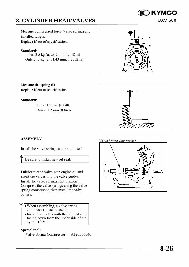
8. CYLINDER HEAD/VALVES
8-26
UXV 500
Measure compressed force (valve spring) andinstalled length.Replace if out of specification.
Standard:Inner: 3.5 kg (at 28.7 mm, 1.148 in) Outer: 13 kg (at 31.43 mm, 1.2572 in)
Measure the spring tilt.Replace if out of specification.
Standard:Inner: 1.2 mm (0.048)Outer: 1.2 mm (0.048)
ASSEMBLY
Install the valve spring seats and oil seal.
Lubricate each valve with engine oil andinsert the valves into the valve guides.Install the valve springs and retainers.Compress the valve springs using the valvespring compressor, then install the valvecotters.
Special tool:Valve Spring Compressor A120E00040
Valve Spring Compressor
Be sure to install new oil seal.*
•When assembling, a valve springcompressor must be used.
• Install the cotters with the pointed endsfacing down from the upper side of thecylinder head.
*

8. CYLINDER HEAD/VALVES
8-27
UXV 500
Tap the valve stems gently with a plastichammer for 2~3 times to firmly seat thecotters.
Be careful not to damage the valves.*
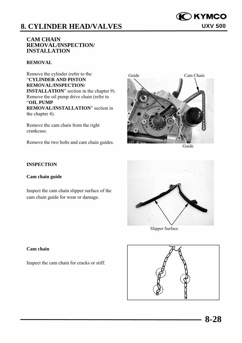
8. CYLINDER HEAD/VALVES
8-28
UXV 500
CAM CHAINREMOVAL/INSPECTION/INSTALLATION
REMOVAL
Remove the cylinder (refer to the“CYLINDER AND PISTONREMOVAL/INSPECTION/INSTALLATION” section in the chapter 9).Remove the oil pump drive chain (refer to“OIL PUMPREMOVAL/INSTALLATION” section inthe chapter 4).
Remove the cam chain from the rightcrankcase.
Remove the two bolts and cam chain guides.
INSPECTION
Cam chain guide
Inspect the cam chain slipper surface of thecam chain guide for wear or damage.
Cam chain
Inspect the cam chain for cracks or stiff.
Guide
Guide Cam Chain
Slipper Surface
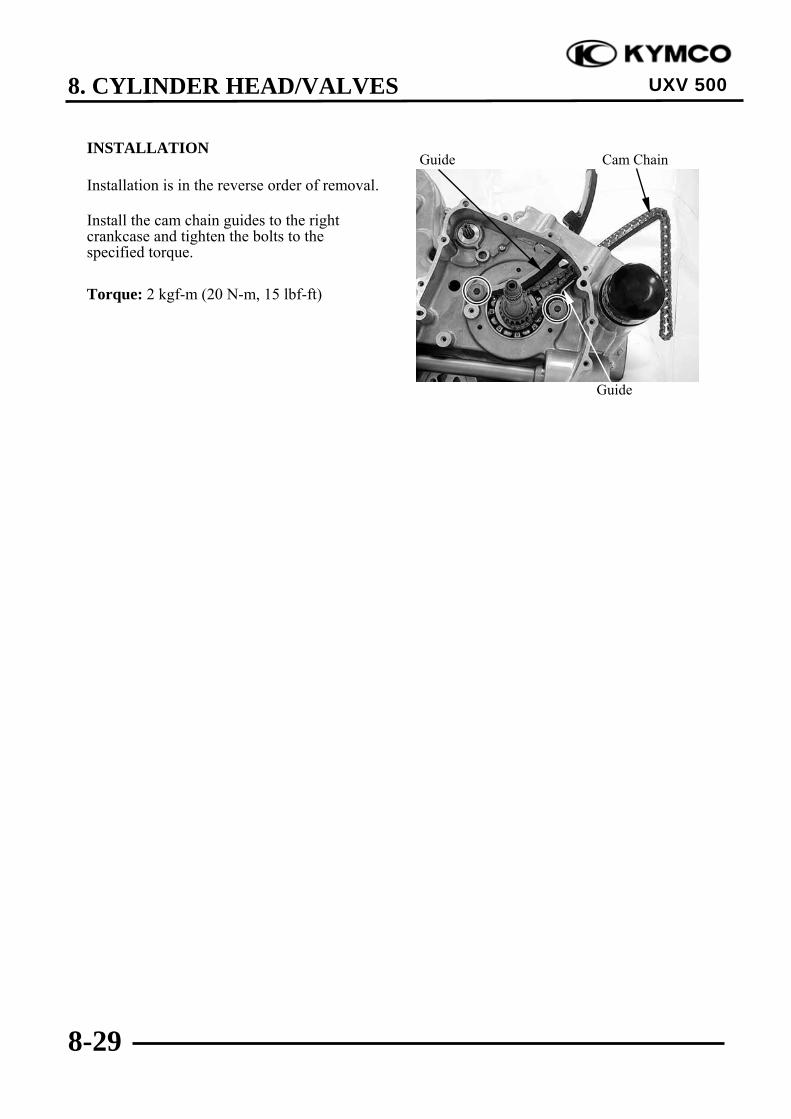
8. CYLINDER HEAD/VALVES
8-29
UXV 500
INSTALLATION
Installation is in the reverse order of removal.
Install the cam chain guides to the rightcrankcase and tighten the bolts to thespecified torque.
Torque: 2 kgf-m (20 N-m, 15 lbf-ft)
Guide
Guide Cam Chain
10. DRIVE PULLEY/DRIVEN PULLEY/CLUTCH
10-0
UXV 500
10 __________________________________________________________________________________
__________________________________________________________________________________
__________________________________________________________________________________
__________________________________________________________________________________
__________________________________________________________________________________
DRIVE PULLEY/DRIVEN PULLEY/CLUTCH__________________________________________________________________________________
SCHEMATIC DRAWING ------------------------------------------------- 10- 1SERVICE INFORMATION------------------------------------------------ 10- 2TROUBLESHOOTING----------------------------------------------------- 10- 2LEFT CRANKCASE COVER REMOVAL/INSTALLATION ------- 10- 3DRIVE PULLEY, DRIVE V-BELT AND DRIVEN PULLEYREMOVAL/INSPECTION/ INSTALLATION ------------------------- 10- 5DRIVE PULLEY DISASSEMBLY/INSPECTION/ASSEMBLY ---- 10- 9DRIVEN PULLEY DISASSEMBLY/INSPECTION/ASSEMBLY-- 10-13CLUTCH REMOVAL/INSTALLATION-------------------------------- 10-17CLUTCH DISASSEMBLY/INSPECTION/ASSEMBLY ------------- 10-21REMOVAL CTV PARTS ON VEHICLE ---------------------------------10-27
10
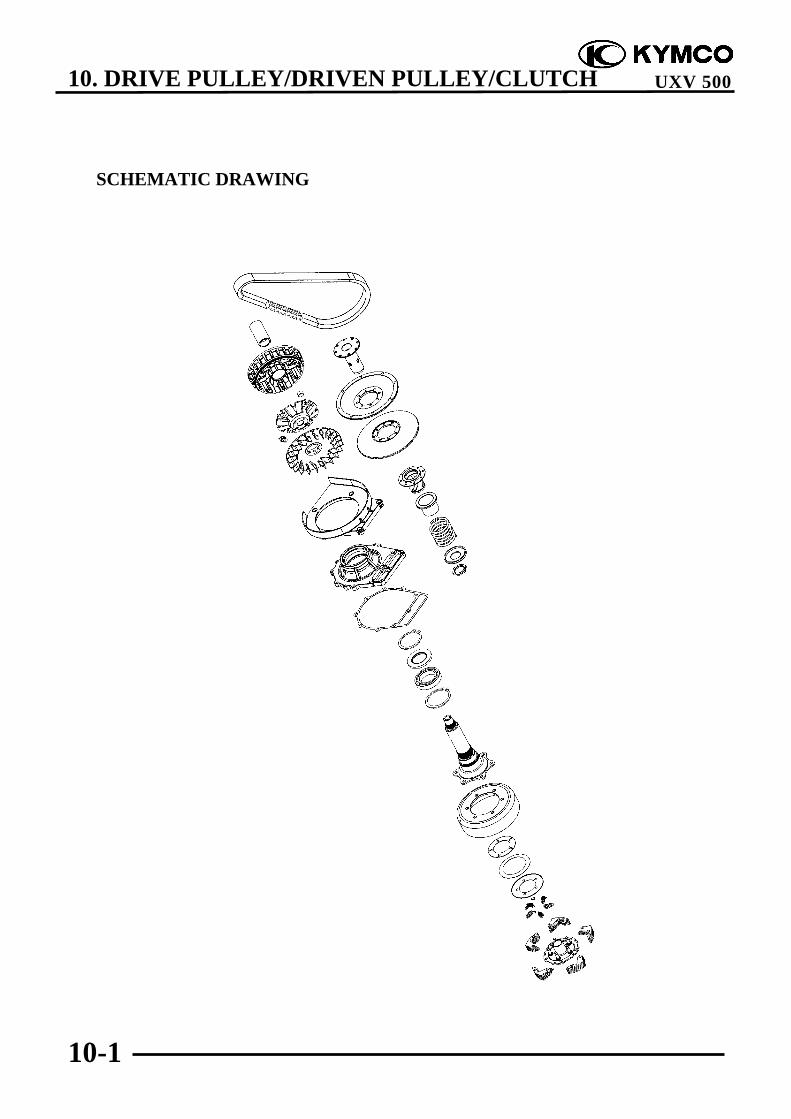
10. DRIVE PULLEY/DRIVEN PULLEY/CLUTCH
10-1
UXV 500
SCHEMATIC DRAWING

10. DRIVE PULLEY/DRIVEN PULLEY/CLUTCH
10-2
UXV 500
SERVICE INFORMATION
GENERAL INSTRUCTIONS• The drive pulley, clutch and driven pulley can be serviced with the engine installed.• Avoid getting grease and oil on the drive belt and pulley faces. Remove any oil or grease from
them to minimize the slipping of drive belt and drive pulley.• Do not apply grease to the movable drive face and weight rollers.
SPECIFICATIONS Unit: mm (in)
Item Standard Service LimitDrive belt width 34.1 (1.364) 30.8 (1.232)Clutch shoe thickness 1.5 (0.06) 1 (0.04)Driven pulley spring 124.3 (4.972) 121.3 (4.852)Weight roller O.D. 29.9 (1.196)~30.1 (1.204) 29.5 (1.18)
TORQUE VALUESDrive pulley nut 14 kgf-m (140 N-m, 100.8 lbf-ft) Apply oil to the threadsClutch nut 14 kgf-m (140 N-m, 100.8 lbf-ft)Driven pulley nut 10 kgf-m (100 N-m, 72 lbf-ft) Apply oil to the threadsDriven pulley assembly plate nut 7.5 kgf-m (75 N-m, 54 lbf-ft)
SPECIAL TOOLSOil seal & bearing install A120E00014Bearing puller A120E00037Y-type holder A120E00056Drive pulley holder A120E00058Driven pulley spring compressor A120E00059
TROUBLESHOOTINGEngine starts but ATV won‘t move Lack of power• Worn drive belt • Worn drive belt• Broken ramp plate • Weak driven face spring• Worn or damaged clutch lining • Worn weight roller• Broken driven face spring • Faulty driven face
Engine stalls or ATV creeps• Broken clutch weight spring

10. DRIVE PULLEY/DRIVEN PULLEY/CLUTCH
10-3
UXV 500
LEFT CRANKCASE COVERREMOVAL/INSTALLATIONREMOVAL
REMOVAL CTV PARTS ON VEHICLEKey Switch “OFF”.Remove the seat, and center cover. cargobed Up then remove the fuel cap.Remove the side panel .R. front andprotector Fuel tank.Remove the tank frame.
Disconnect the fuel tube from fuel pump.
Disconnect the fuel unit connectors.Remove the 4 bolts and from the fuel tank,then remove the fuel tank.Remove the CVT cover bolts.Disconnect the CVT cover.Remove the CVT parts.Remove the ten bolts, remove the leftcrankcase cover and rubber gasket.(refer to chapter 10-27)
Remove the two dowel pins.
INSTALLATION
Install the rubber gasket onto the leftcrankcase cover.Install the two dowel pins onto the leftcrankcase cover.
CVT Cover
Bolts
Dowel Pins Rubber Gasket
Dowel Pins

10. DRIVE PULLEY/DRIVEN PULLEY/CLUTCH
10-4
UXV 500
Install the left crankcase cover and tightenthe ten bolts diagonally to specified torque.
Torque: 1 kgf-m (10 N-m, 7.2 lbf-ft)
CVT Cover
Bolts

10. DRIVE PULLEY/DRIVEN PULLEY/CLUTCH
10-5
UXV 500
DRIVE PULLEY, DRIVE V-BELTAND DRIVEN PULLEYREMOVAL/INSPECTION/INSTALLATION
REMOVAL
Use the special tool to hold the drive pulley,then remove the nut and washer.
Special tool:Drive pulley holder A120E00058
Remove the drive pulley.
Use the special tool to hold the drivenpulley, then remove the nut.
Special tool:Y-type holder A120E00056
Remove the driven pulley and V-belt.
Remove the driven pulley washer.Remove the drive pulley face.
Drive Pulley Nut/Washer
Drive Pulley Holder
Y-type Holder
Nut
Washer
Drive Pulley Face Stopper Lever Shaft Nut
Do not loosen the stopper lever shaft nut,it may cause stopper lever bolt loosen.To tighten the stopper lever bolt mustremove the crankcase (refer to the“TRANSMISSION REMOVAL/INSPECTION/INSTALLATION”section in the chapter 11).
*
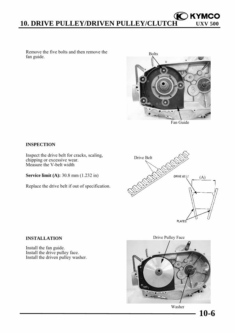
10. DRIVE PULLEY/DRIVEN PULLEY/CLUTCH
10-6
UXV 500
Remove the five bolts and then remove thefan guide.
INSPECTION
Inspect the drive belt for cracks, scaling,chipping or excessive wear.Measure the V-belt width
Service limit (A): 30.8 mm (1.232 in)
Replace the drive belt if out of specification.
INSTALLATION
Install the fan guide.Install the drive pulley face.Install the driven pulley washer.
Fan Guide
Bolts
Washer
Drive Pulley Face
Drive Belt
(A)

10. DRIVE PULLEY/DRIVEN PULLEY/CLUTCH
10-7
UXV 500
Place a block on the plate nut.Compress the spring by using acommercially available puller, install thedrive belt.
Install the driven pulley assembly and driveV-belt.Use the special tool to hold driven pulley,then tighten the nut to the specified torque.
Torque: 10 kgf-m (100 N-m, 72 lbf-ft)Apply oil to the threads
Special tools:Y-type holder A120E00056
Apply lubricant to the drive face boss innersurface, then install the drive pulley.
The drive belt should be installed sothat the arrows on the drive beltperiphery point in the normal turningdirection.
The drive belt contact surface of thedriven face should be thoroughlycleaned.
*
Drive Face Boss
Apply lubricant
Block
Y-type Holder
Nut

10. DRIVE PULLEY/DRIVEN PULLEY/CLUTCH
10-8
UXV 500
Install the drive pulley assembly.Install the washer and nut.
Use the special tool to hold drive pulley,then tighten the nut to the specified torque.
Torque: 14 kgf-m (140 N-m, 100.8 lbf-ft)Apply oil to the threads
Special tool:Drive pulley holder A120E00058
Make sure the “OUT SIDE” marks onthe washer faces the left crankcase cover.
*
Drive Pulley Nut/Washer
Drive Pulley Holder
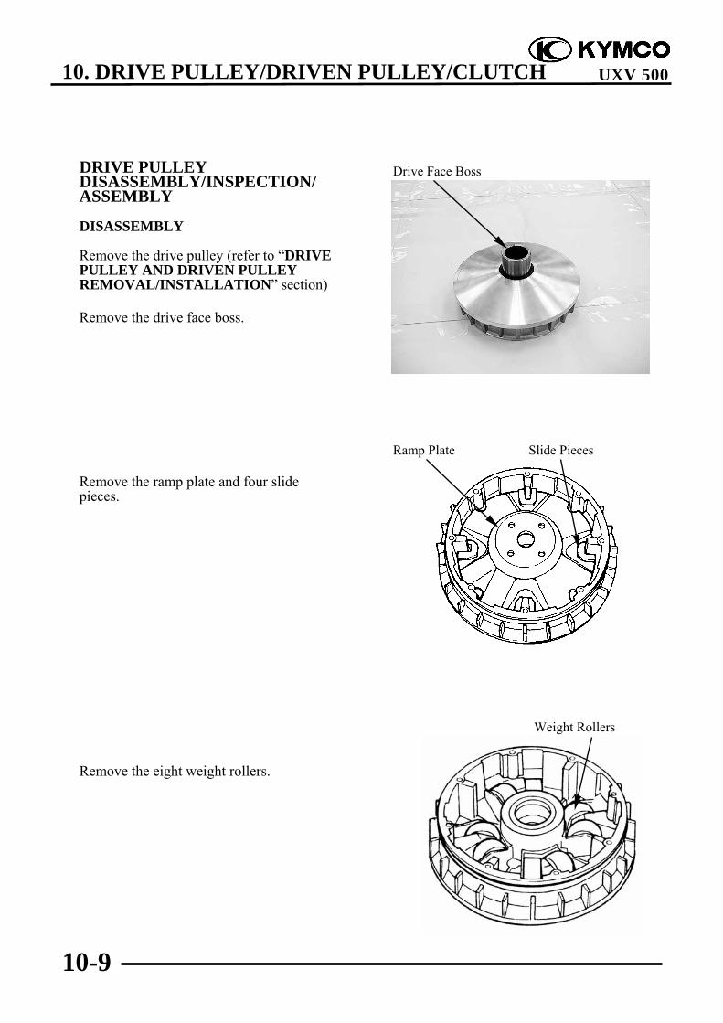
10. DRIVE PULLEY/DRIVEN PULLEY/CLUTCH
10-9
UXV 500
DRIVE PULLEYDISASSEMBLY/INSPECTION/ASSEMBLY
DISASSEMBLY
Remove the drive pulley (refer to “DRIVEPULLEY AND DRIVEN PULLEYREMOVAL/INSTALLATION” section)
Remove the drive face boss.
Remove the ramp plate and four slidepieces.
Remove the eight weight rollers.
Drive Face Boss
Ramp Plate Slide Pieces
Weight Rollers
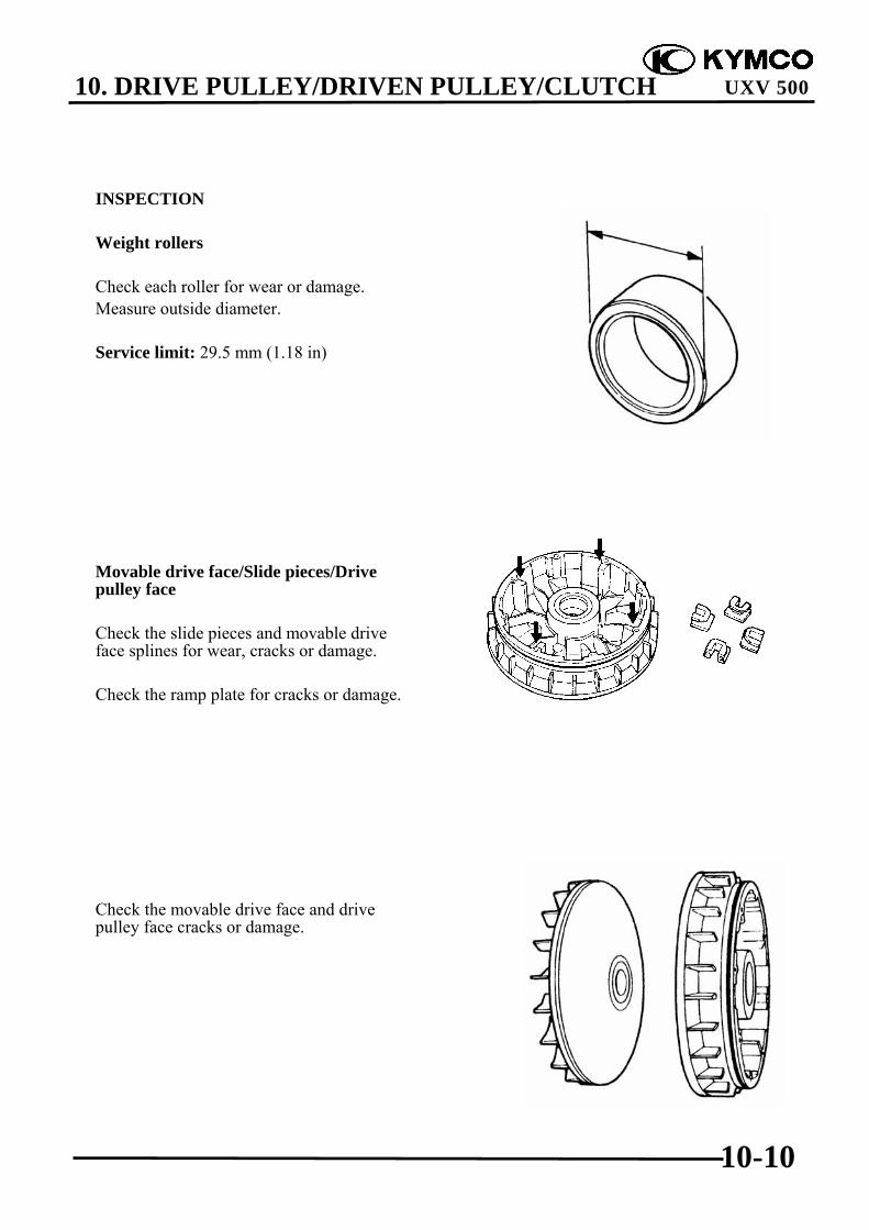
10. DRIVE PULLEY/DRIVEN PULLEY/CLUTCH
10-10
UXV 500
INSPECTION
Weight rollers
Check each roller for wear or damage.Measure outside diameter.
Service limit: 29.5 mm (1.18 in)
Movable drive face/Slide pieces/Drivepulley face
Check the slide pieces and movable driveface splines for wear, cracks or damage.
Check the ramp plate for cracks or damage.
Check the movable drive face and drivepulley face cracks or damage.
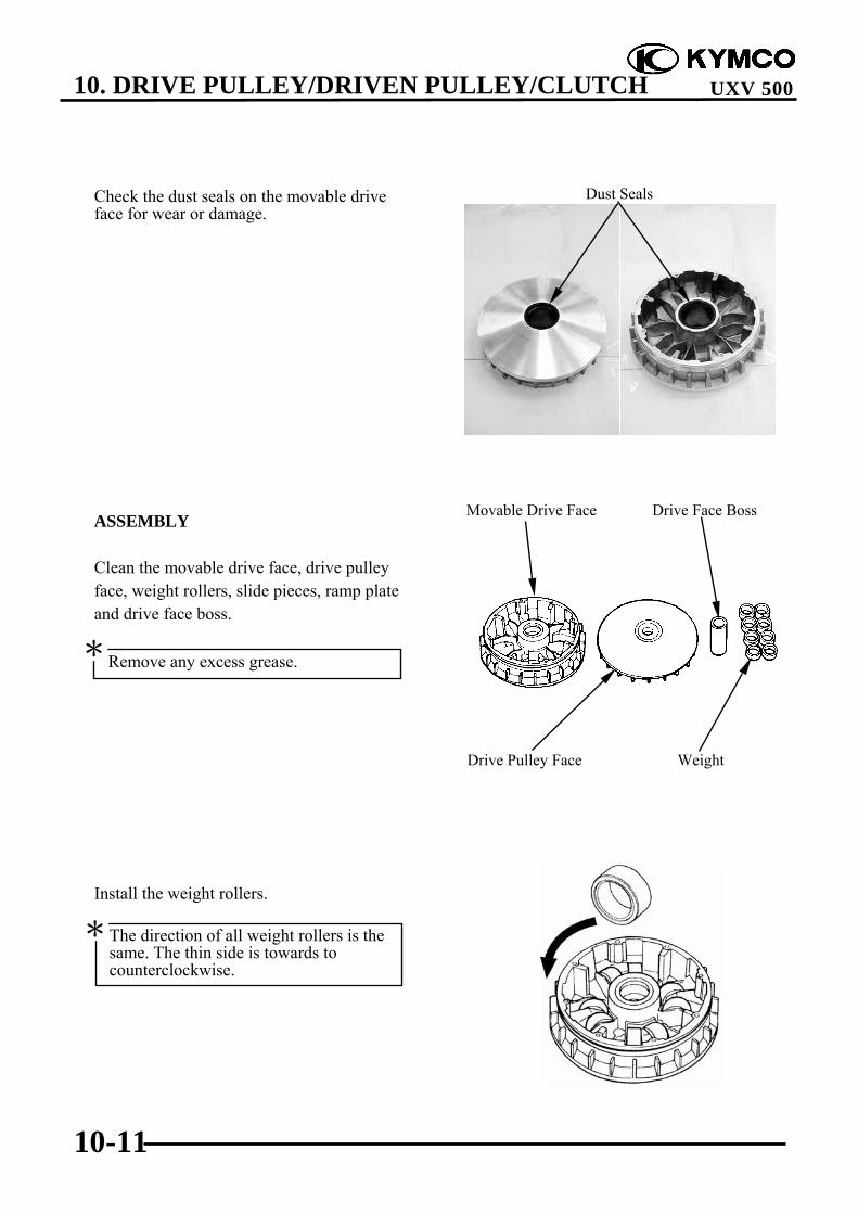
10. DRIVE PULLEY/DRIVEN PULLEY/CLUTCH
10-11
UXV 500
Check the dust seals on the movable driveface for wear or damage.
ASSEMBLY
Clean the movable drive face, drive pulleyface, weight rollers, slide pieces, ramp plateand drive face boss.
Install the weight rollers.
Remove any excess grease.*
The direction of all weight rollers is thesame. The thin side is towards tocounterclockwise.
*
Dust Seals
Drive Pulley Face Weight
Movable Drive Face Drive Face Boss

10. DRIVE PULLEY/DRIVEN PULLEY/CLUTCH
10-12
UXV 500
Install the slide pieces and ramp plate.
Install the drive face boss.
Drive Face Boss
Ramp Plate Slide Pieces
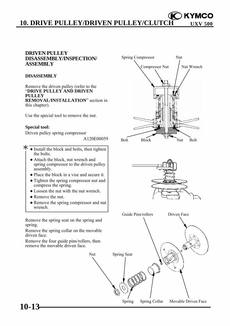
10. DRIVE PULLEY/DRIVEN PULLEY/CLUTCH
10-13
UXV 500
DRIVEN PULLEYDISASSEMBLY/INSPECTION/ASSEMBLY
DISASSEMBLY
Remove the driven pulley (refer to the“DRIVE PULLEY AND DRIVENPULLEYREMOVAL/INSTALLATION” section inthis chapter).
Use the special tool to remove the nut.
Special tool:Driven pulley spring compressor
A120E00059
Remove the spring seat on the spring andspring.Remove the spring collar on the movabledriven face.Remove the four guide pins/rollers, thenremove the movable driven face.
Install the block and bolts, then tightenthe bolts.
Attach the block, nut wrench andspring compressor to the driven pulleyassembly.
Place the block in a vise and secure it. Tighten the spring compressor nut and
compress the spring. Loosen the nut with the nut wrench. Remove the nut. Remove the spring compressor and nut
wrench.
*Bolt Block Nut Bolt
Spring Compressor Nut
Spring Spring Collar Movable Driven Face
Guide Pins/rollers Driven Face
Compressor Nut Nut Wrench
Nut Spring Seat

10. DRIVE PULLEY/DRIVEN PULLEY/CLUTCH
10-14
UXV 500
Remove the O-rings and dust seals from themovable driven face.
INSPECTION
Check the driven pulley for smoothoperation.If any scratches or damage is found thenreplace as a set.
Check the torque cam grooves for wear ordamage.
Check guide pins and rollers for wear ordamage.If any scratches or damage is found thenreplace as a set.
Check the spring for damage.Measure the spring free length.
Service limit: 121.3 mm (4.852 in)
Guide Pins
Grooves
O-ring O-ring
Dust Seal Dust Seal
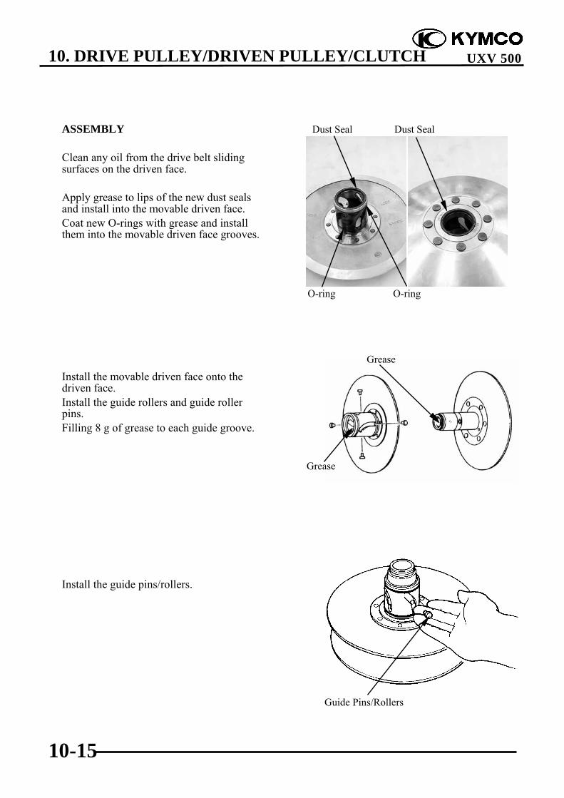
10. DRIVE PULLEY/DRIVEN PULLEY/CLUTCH
10-15
UXV 500
ASSEMBLY
Clean any oil from the drive belt slidingsurfaces on the driven face.
Apply grease to lips of the new dust sealsand install into the movable driven face.Coat new O-rings with grease and installthem into the movable driven face grooves.
Install the movable driven face onto thedriven face.Install the guide rollers and guide rollerpins.Filling 8 g of grease to each guide groove.
Install the guide pins/rollers.
Grease
Grease
Guide Pins/Rollers
O-ring O-ring
Dust Seal Dust Seal

10. DRIVE PULLEY/DRIVEN PULLEY/CLUTCH
10-16
UXV 500
Install spring collar.Use the special tool to install spring andspring seat, then install and tighten the nutto the specified torque.
Torque: 7.5 kgf-m (75 N-m, 54 lbf-ft)
Special tool:Driven pulley spring compressor
A120E00059
Attach the block, nut, nut wrench andspring compressor to the driven pulleyassembly.
Place the block in a vise and secure it. Tighten the spring compressor nut and
compress the spring. Install the nut and tighten it to the
specified torque with the nut wrench. Remove the spring compressor and nut
wrench.
*
Bolt Block Nut Bolt
Spring Compressor Nut
Compressor Nut Nut Wrench

10. DRIVE PULLEY/DRIVEN PULLEY/CLUTCH
10-17
UXV 500
CLUTCHREMOVAL/INSTALLATION
REMOVAL
Remove the fan guide (refer to the “DRIVEPULLEY AND DRIVEN PULLEYREMOVAL/INSTALLATION” section inthis chapter).
Remove the nine bolts and then remove theclutch housing assembly and one-wayclutch bearing.
Remove the two dowel pins and gasket.
Using a chisel, unlock the nut.
Working in crisscross pattern, looseneach bolt 1/4 of a turn. Remove themafter all of them are loosened.
* Clutch Housing Assembly
One-way Clutch Bearing
Gasket
Dowel Pins
Nut

10. DRIVE PULLEY/DRIVEN PULLEY/CLUTCH
10-18
UXV 500
Use the special tool to hold clutch carrierassembly.
Special tool:Y-type holder A120E00056
Not USA type:Use the 26mm socket wrench to remove thenut and washer.
USA type:Remove the nut and collar.
Remove the clutch carrier assembly andcollar.
Clutch Carrier Assembly
Collar
t Wrench
26mm nut

10. DRIVE PULLEY/DRIVEN PULLEY/CLUTCH
10-19
UXV 500
INSTALLATION
Apply clean engine oil to the clutch carrierassembly and collar, then install the collarand clutch carrier assembly.
Install the washer
Use the special tools to install and tightenthe nut to the specified torque.
Torque: 14 kgf-m (140 N-m, 100.8 lbf-ft)
Special tool:Y-type holder A120E00056
Stake the nut with a center punch.
Clutch Carrier Assembly
Collar
Nut

10. DRIVE PULLEY/DRIVEN PULLEY/CLUTCH
10-20
UXV 500
Install the dowel pins and gasket.
Apply molybdenum disulfide grease to theone-way clutch bearing, then install it.Install the clutch housing and tighten thebolts to the specified torque in a crisscrosspattern in 2-3 steps.
Torque: 1 kgf-m (10 N-m, 7.2 lbf-ft)
Gasket Nut/Washer
Dowel Pins
Clutch Housing Assembly
One-way Clutch Bearing

10. DRIVE PULLEY/DRIVEN PULLEY/CLUTCH
10-21
UXV 500
CLUTCHDISASSEMBLY/INSPECTION/ASSEMBLY
DISASSEMBLY
Remove the clutch housing and clutchcarrier assembly (refer to the “CLUTCHREMOVAL/INSTALLATION” section inthis chapter).
Remove the one-way clutch bearing fromthe clutch housing.
Clutch housing removal (not USA type):
Remove the oil seal.Remove the snap ring, then remove theclutch housing.
Remove the snap ring, then remove thebearing.
Snap Ring
Oil Seal
Bearing
Snap Ring
One-way Clutch Bearing

10. DRIVE PULLEY/DRIVEN PULLEY/CLUTCH
10-22
UXV 500
Clutch housing removal (USA type):
Remove the clutch housing.
Remove the oil seal, then remove thebearing.
Clutch Housing
Bearing
Oil Seal

10. DRIVE PULLEY/DRIVEN PULLEY/CLUTCH
10-23
UXV 500
INSPECTION
Check the clutch housing for heat damage,wear or damage.
Check the one-way clutch bearing forchafing, wear or damage.
Check the clutch shoe for heat damage.
Measure the clutch shoe thickness.
Service limit (A): 1 mm (0.04 in)
Only USA type:
Turn the crankshaft bearing for smoothlyand check for excessive play.
Replace the one-way clutch assemblyand clutch housing as a set.
*
Bearing
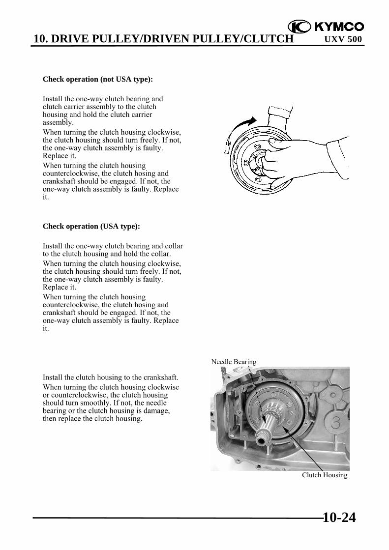
10. DRIVE PULLEY/DRIVEN PULLEY/CLUTCH
10-24
UXV 500
Check operation (not USA type):
Install the one-way clutch bearing andclutch carrier assembly to the clutchhousing and hold the clutch carrierassembly.When turning the clutch housing clockwise,the clutch housing should turn freely. If not,the one-way clutch assembly is faulty.Replace it.When turning the clutch housingcounterclockwise, the clutch hosing andcrankshaft should be engaged. If not, theone-way clutch assembly is faulty. Replaceit.
Check operation (USA type):
Install the one-way clutch bearing and collarto the clutch housing and hold the collar.When turning the clutch housing clockwise,the clutch housing should turn freely. If not,the one-way clutch assembly is faulty.Replace it.When turning the clutch housingcounterclockwise, the clutch hosing andcrankshaft should be engaged. If not, theone-way clutch assembly is faulty. Replaceit.
Install the clutch housing to the crankshaft.When turning the clutch housing clockwiseor counterclockwise, the clutch housingshould turn smoothly. If not, the needlebearing or the clutch housing is damage,then replace the clutch housing.
Clutch Housing
Needle Bearing

10. DRIVE PULLEY/DRIVEN PULLEY/CLUTCH
10-25
UXV 500
ASSEMBLY
Clutch housing installation (not USAtype):
Apply clean engine oil, then install the newbearing.Install the snap ring.
Install the clutch housing.Install the snap ring.Apply lightweight lithium-soap base greaseto the new oil seal lip, then install the newoil seal.
Clutch housing installation (USA type):
Apply clean engine oil, then install the newbearing.
Bearing
Snap Ring
Snap Ring
Oil Seal
Bearing
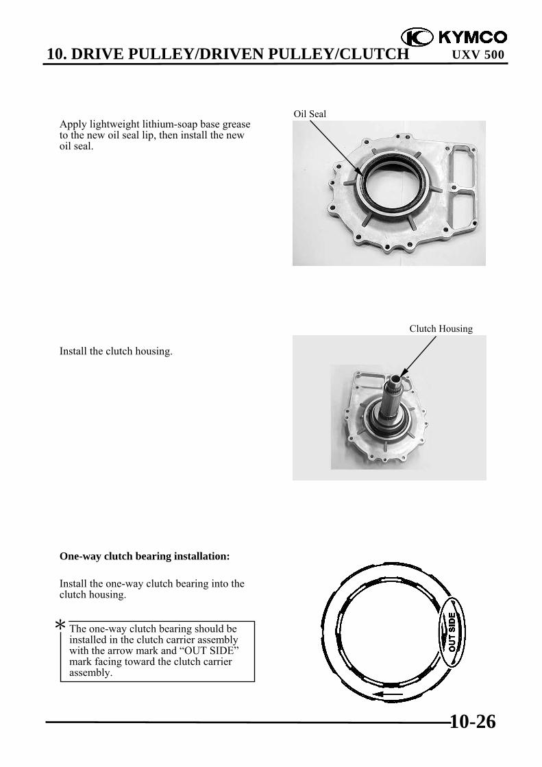
10. DRIVE PULLEY/DRIVEN PULLEY/CLUTCH
10-26
UXV 500
Apply lightweight lithium-soap base greaseto the new oil seal lip, then install the newoil seal.
Install the clutch housing.
One-way clutch bearing installation:
Install the one-way clutch bearing into theclutch housing.
Oil Seal
Clutch Housing
The one-way clutch bearing should beinstalled in the clutch carrier assemblywith the arrow mark and “OUT SIDE”mark facing toward the clutch carrierassembly.
*

10. DRIVE PULLEY/DRIVEN PULLEY/CLUTCH
10-27
UXV 500
REMOVAL CTV PARTS ON VEHICLEKey Switch “OFF”.Remove the seat, and center cover. cargobed Up then remove the fuel cap.Remove the side panel .R.front andprotector Fuel tank.Remove the tank frame.
Disconnect the fuel tube from fuel pump.
Disconnect the fuel unit connectors.Remove the 4 screws and from the fuel tank,then remove the fuel tank.Remove the CVT cover screws.Disconnect the CVT cover.Remove the CVT parts.
INSTALLATION
Installation is in the reverse order of removal.

10. DRIVE PULLEY/DRIVEN PULLEY/CLUTCH
10-0
UXV 500
10 __________________________________________________________________________________
__________________________________________________________________________________
__________________________________________________________________________________
__________________________________________________________________________________
__________________________________________________________________________________
DRIVE PULLEY/DRIVEN PULLEY/CLUTCH__________________________________________________________________________________
SCHEMATIC DRAWING ------------------------------------------------- 10- 1SERVICE INFORMATION------------------------------------------------ 10- 2TROUBLESHOOTING----------------------------------------------------- 10- 2LEFT CRANKCASE COVER REMOVAL/INSTALLATION ------- 10- 3DRIVE PULLEY, DRIVE V-BELT AND DRIVEN PULLEYREMOVAL/INSPECTION/ INSTALLATION ------------------------- 10- 5DRIVE PULLEY DISASSEMBLY/INSPECTION/ASSEMBLY ---- 10- 9DRIVEN PULLEY DISASSEMBLY/INSPECTION/ASSEMBLY-- 10-13CLUTCH REMOVAL/INSTALLATION-------------------------------- 10-17CLUTCH DISASSEMBLY/INSPECTION/ASSEMBLY ------------- 10-21REMOVEL CTV PARTS ON VEHICLE ---------------------------------10-27
10

10. DRIVE PULLEY/DRIVEN PULLEY/CLUTCH
10-1
UXV 500
SCHEMATIC DRAWING

10. DRIVE PULLEY/DRIVEN PULLEY/CLUTCH
10-2
UXV 500
SERVICE INFORMATION
GENERAL INSTRUCTIONS• The drive pulley, clutch and driven pulley can be serviced with the engine installed.• Avoid getting grease and oil on the drive belt and pulley faces. Remove any oil or grease from
them to minimize the slipping of drive belt and drive pulley.• Do not apply grease to the movable drive face and weight rollers.
SPECIFICATIONS Unit: mm (in)
Item Standard Service LimitDrive belt width 34.1 (1.364) 30.8 (1.232)Clutch shoe thickness 1.5 (0.06) 1 (0.04)Driven pulley spring 124.3 (4.972) 121.3 (4.852)Weight roller O.D. 29.9 (1.196)~30.1 (1.204) 29.5 (1.18)
TORQUE VALUESDrive pulley nut 14 kgf-m (140 N-m, 100.8 lbf-ft) Apply oil to the threadsClutch nut 14 kgf-m (140 N-m, 100.8 lbf-ft)Driven pulley nut 10 kgf-m (100 N-m, 72 lbf-ft) Apply oil to the threadsDriven pulley assembly plate nut 7.5 kgf-m (75 N-m, 54 lbf-ft)
SPECIAL TOOLSOil seal & bearing install A120E00014Bearing puller A120E00037Y-type holder A120E00056Drive pulley holder A120E00058Driven pulley spring compressor A120E00059
TROUBLESHOOTINGEngine starts but ATV won‘t move Lack of power• Worn drive belt • Worn drive belt• Broken ramp plate • Weak driven face spring• Worn or damaged clutch lining • Worn weight roller• Broken driven face spring • Faulty driven face
Engine stalls or ATV creeps• Broken clutch weight spring
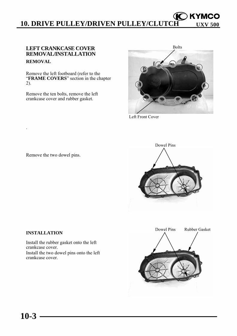
10. DRIVE PULLEY/DRIVEN PULLEY/CLUTCH
10-3
UXV 500
LEFT CRANKCASE COVERREMOVAL/INSTALLATIONREMOVAL
Remove the left footboard (refer to the“FRAME COVERS” section in the chapter2).
Remove the ten bolts, remove the leftcrankcase cover and rubber gasket.
.
Remove the two dowel pins.
INSTALLATION
Install the rubber gasket onto the leftcrankcase cover.Install the two dowel pins onto the leftcrankcase cover.
Left Front Cover
Bolts
Dowel Pins Rubber Gasket
Dowel Pins

10. DRIVE PULLEY/DRIVEN PULLEY/CLUTCH
10-4
UXV 500
Install the left crankcase cover and tightenthe ten bolts diagonally to specified torque.
Torque: 1 kgf-m (10 N-m, 7.2 lbf-ft)
Left Front Cover
Bolts

10. DRIVE PULLEY/DRIVEN PULLEY/CLUTCH
10-5
UXV 500
DRIVE PULLEY, DRIVE V-BELTAND DRIVEN PULLEYREMOVAL/INSPECTION/INSTALLATION
REMOVAL
Use the special tool to hold the drive pulley,then remove the nut and washer.
Special tool:Drive pulley holder A120E00058
Remove the drive pulley.
Use the special tool to hold the drivenpulley, then remove the nut.
Special tool:Y-type holder A120E00056
Remove the driven pulley and V-belt.
Remove the driven pulley washer.Remove the drive pulley face.
Drive Pulley Nut/Washer
Drive Pulley Holder
Y-type Holder
Nut
Washer
Drive Pulley Face Stopper Lever Shaft Nut
Do not loosen the stopper lever shaft nut,it may cause stopper lever bolt loosen.To tighten the stopper lever bolt mustremove the crankcase (refer to the“TRANSMISSION REMOVAL/INSPECTION/INSTALLATION”section in the chapter 11).
*
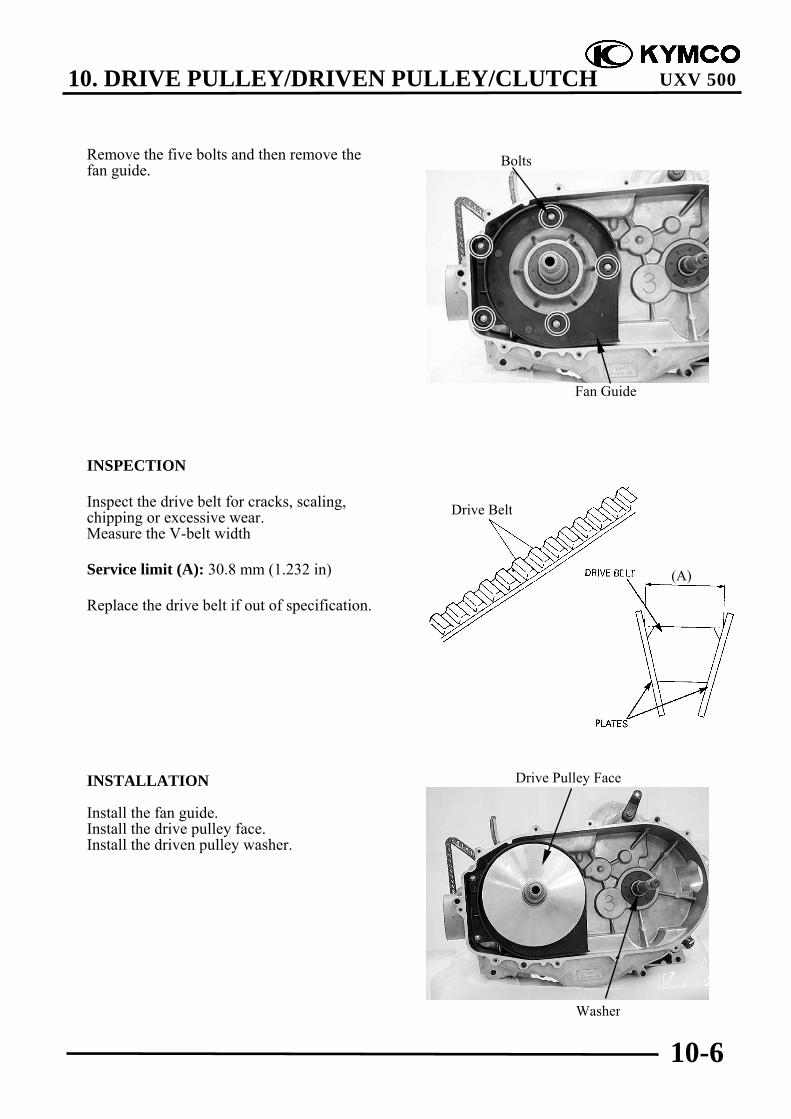
10. DRIVE PULLEY/DRIVEN PULLEY/CLUTCH
10-6
UXV 500
Remove the five bolts and then remove thefan guide.
INSPECTION
Inspect the drive belt for cracks, scaling,chipping or excessive wear.Measure the V-belt width
Service limit (A): 30.8 mm (1.232 in)
Replace the drive belt if out of specification.
INSTALLATION
Install the fan guide.Install the drive pulley face.Install the driven pulley washer.
Fan Guide
Bolts
Washer
Drive Pulley Face
Drive Belt
(A)
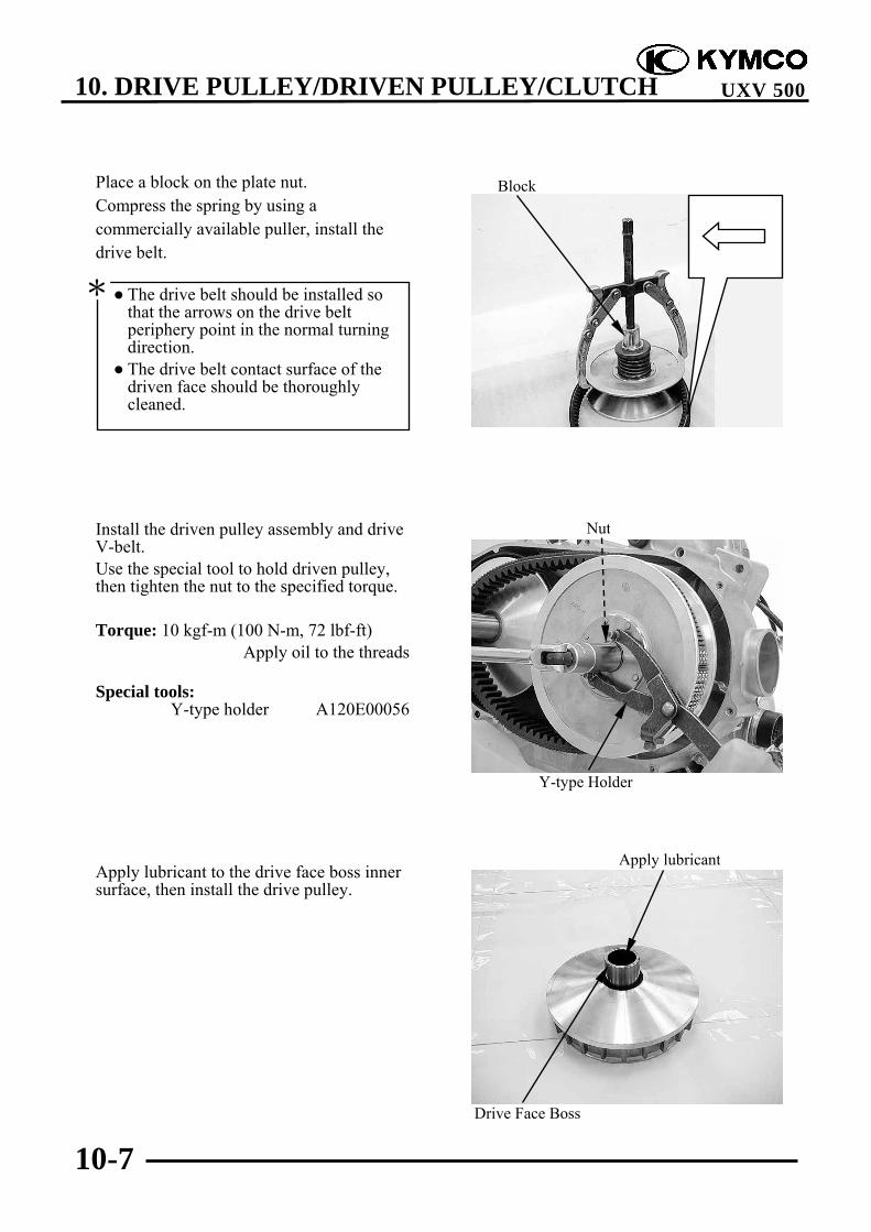
10. DRIVE PULLEY/DRIVEN PULLEY/CLUTCH
10-7
UXV 500
Place a block on the plate nut.Compress the spring by using acommercially available puller, install thedrive belt.
Install the driven pulley assembly and driveV-belt.Use the special tool to hold driven pulley,then tighten the nut to the specified torque.
Torque: 10 kgf-m (100 N-m, 72 lbf-ft)Apply oil to the threads
Special tools:Y-type holder A120E00056
Apply lubricant to the drive face boss innersurface, then install the drive pulley.
The drive belt should be installed sothat the arrows on the drive beltperiphery point in the normal turningdirection.
The drive belt contact surface of thedriven face should be thoroughlycleaned.
*
Drive Face Boss
Apply lubricant
Block
Y-type Holder
Nut

10. DRIVE PULLEY/DRIVEN PULLEY/CLUTCH
10-8
UXV 500
Install the drive pulley assembly.Install the washer and nut.
Use the special tool to hold drive pulley,then tighten the nut to the specified torque.
Torque: 14 kgf-m (140 N-m, 100.8 lbf-ft)Apply oil to the threads
Special tool:Drive pulley holder A120E00058
Make sure the “OUT SIDE” marks onthe washer faces the left crankcase cover.
*
Drive Pulley Nut/Washer
Drive Pulley Holder

10. DRIVE PULLEY/DRIVEN PULLEY/CLUTCH
10-9
UXV 500
DRIVE PULLEYDISASSEMBLY/INSPECTION/ASSEMBLY
DISASSEMBLY
Remove the drive pulley (refer to “DRIVEPULLEY AND DRIVEN PULLEYREMOVAL/INSTALLATION” section)
Remove the drive face boss.
Remove the ramp plate and four slidepieces.
Remove the eight weight rollers.
Drive Face Boss
Ramp Plate Slide Pieces
Weight Rollers

10. DRIVE PULLEY/DRIVEN PULLEY/CLUTCH
10-10
UXV 500
INSPECTION
Weight rollers
Check each roller for wear or damage.Measure outside diameter.
Service limit: 29.5 mm (1.18 in)
Movable drive face/Slide pieces/Drivepulley face
Check the slide pieces and movable driveface splines for wear, cracks or damage.
Check the ramp plate for cracks or damage.
Check the movable drive face and drivepulley face cracks or damage.

10. DRIVE PULLEY/DRIVEN PULLEY/CLUTCH
10-11
UXV 500
Check the dust seals on the movable driveface for wear or damage.
ASSEMBLY
Clean the movable drive face, drive pulleyface, weight rollers, slide pieces, ramp plateand drive face boss.
Install the weight rollers.
Remove any excess grease.*
The direction of all weight rollers is thesame. The thin side is towards tocounterclockwise.
*
Dust Seals
Drive Pulley Face Weight
Movable Drive Face Drive Face Boss

10. DRIVE PULLEY/DRIVEN PULLEY/CLUTCH
10-12
UXV 500
Install the slide pieces and ramp plate.
Install the drive face boss.
Drive Face Boss
Ramp Plate Slide Pieces
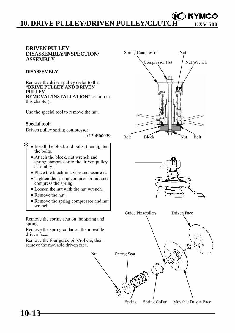
10. DRIVE PULLEY/DRIVEN PULLEY/CLUTCH
10-13
UXV 500
DRIVEN PULLEYDISASSEMBLY/INSPECTION/ASSEMBLY
DISASSEMBLY
Remove the driven pulley (refer to the“DRIVE PULLEY AND DRIVENPULLEYREMOVAL/INSTALLATION” section inthis chapter).
Use the special tool to remove the nut.
Special tool:Driven pulley spring compressor
A120E00059
Remove the spring seat on the spring andspring.Remove the spring collar on the movabledriven face.Remove the four guide pins/rollers, thenremove the movable driven face.
Install the block and bolts, then tightenthe bolts.
Attach the block, nut wrench andspring compressor to the driven pulleyassembly.
Place the block in a vise and secure it. Tighten the spring compressor nut and
compress the spring. Loosen the nut with the nut wrench. Remove the nut. Remove the spring compressor and nut
wrench.
*Bolt Block Nut Bolt
Spring Compressor Nut
Spring Spring Collar Movable Driven Face
Guide Pins/rollers Driven Face
Compressor Nut Nut Wrench
Nut Spring Seat

10. DRIVE PULLEY/DRIVEN PULLEY/CLUTCH
10-14
UXV 500
Remove the O-rings and dust seals from themovable driven face.
INSPECTION
Check the driven pulley for smoothoperation.If any scratches or damage is found thenreplace as a set.
Check the torque cam grooves for wear ordamage.
Check guide pins and rollers for wear ordamage.If any scratches or damage is found thenreplace as a set.
Check the spring for damage.Measure the spring free length.
Service limit: 121.3 mm (4.852 in)
Guide Pins
Grooves
O-ring O-ring
Dust Seal Dust Seal

10. DRIVE PULLEY/DRIVEN PULLEY/CLUTCH
10-15
UXV 500
ASSEMBLY
Clean any oil from the drive belt slidingsurfaces on the driven face.
Apply grease to lips of the new dust sealsand install into the movable driven face.Coat new O-rings with grease and installthem into the movable driven face grooves.
Install the movable driven face onto thedriven face.Install the guide rollers and guide rollerpins.Filling 8 g of grease to each guide groove.
Install the guide pins/rollers.
Grease
Grease
Guide Pins/Rollers
O-ring O-ring
Dust Seal Dust Seal

10. DRIVE PULLEY/DRIVEN PULLEY/CLUTCH
10-16
UXV 500
Install spring collar.Use the special tool to install spring andspring seat, then install and tighten the nutto the specified torque.
Torque: 7.5 kgf-m (75 N-m, 54 lbf-ft)
Special tool:Driven pulley spring compressor
A120E00059
Attach the block, nut, nut wrench andspring compressor to the driven pulleyassembly.
Place the block in a vise and secure it. Tighten the spring compressor nut and
compress the spring. Install the nut and tighten it to the
specified torque with the nut wrench. Remove the spring compressor and nut
wrench.
*
Bolt Block Nut Bolt
Spring Compressor Nut
Compressor Nut Nut Wrench

10. DRIVE PULLEY/DRIVEN PULLEY/CLUTCH
10-17
UXV 500
CLUTCHREMOVAL/INSTALLATION
REMOVAL
Remove the fan guide (refer to the “DRIVEPULLEY AND DRIVEN PULLEYREMOVAL/INSTALLATION” section inthis chapter).
Remove the nine bolts and then remove theclutch housing assembly and one-wayclutch bearing.
Remove the two dowel pins and gasket.
Using a chisel, unlock the nut.
Working in crisscross pattern, looseneach bolt 1/4 of a turn. Remove themafter all of them are loosened.
* Clutch Housing Assembly
One-way Clutch Bearing
Gasket
Dowel Pins
Nut
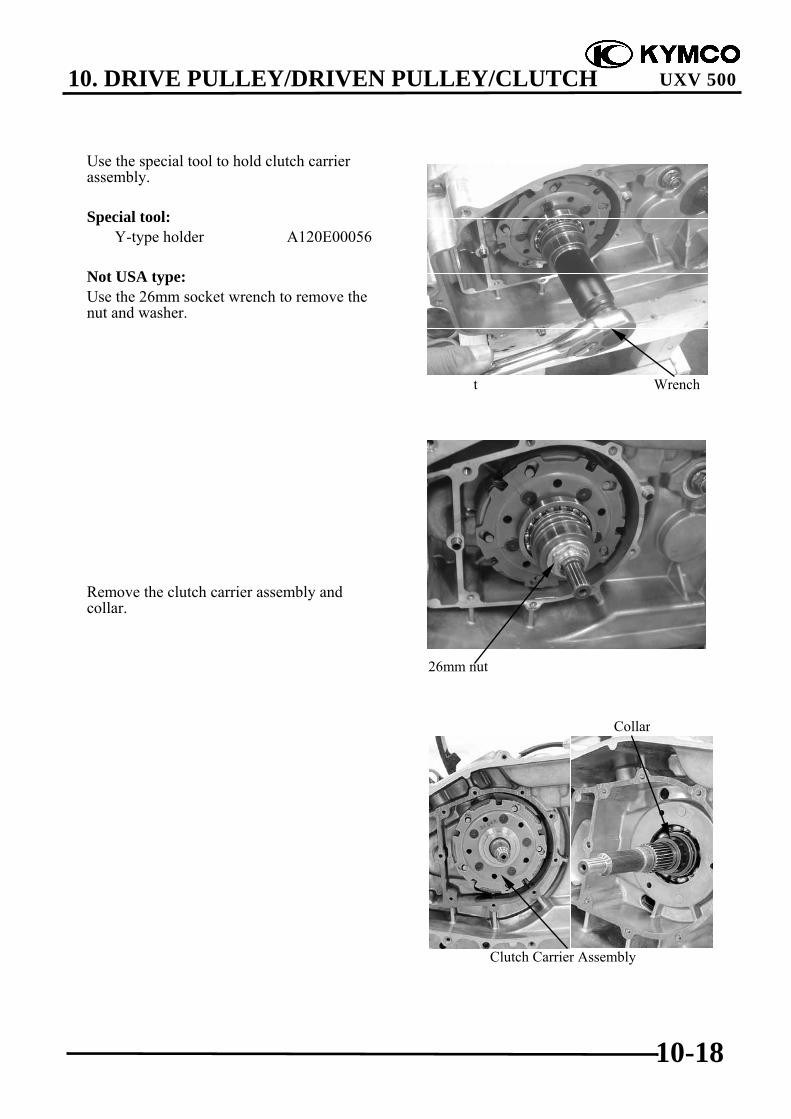
10. DRIVE PULLEY/DRIVEN PULLEY/CLUTCH
10-18
UXV 500
Use the special tool to hold clutch carrierassembly.
Special tool:Y-type holder A120E00056
Not USA type:Use the 26mm socket wrench to remove thenut and washer.
USA type:Remove the nut and collar.
Remove the clutch carrier assembly andcollar.
Clutch Carrier Assembly
Collar
t Wrench
26mm nut
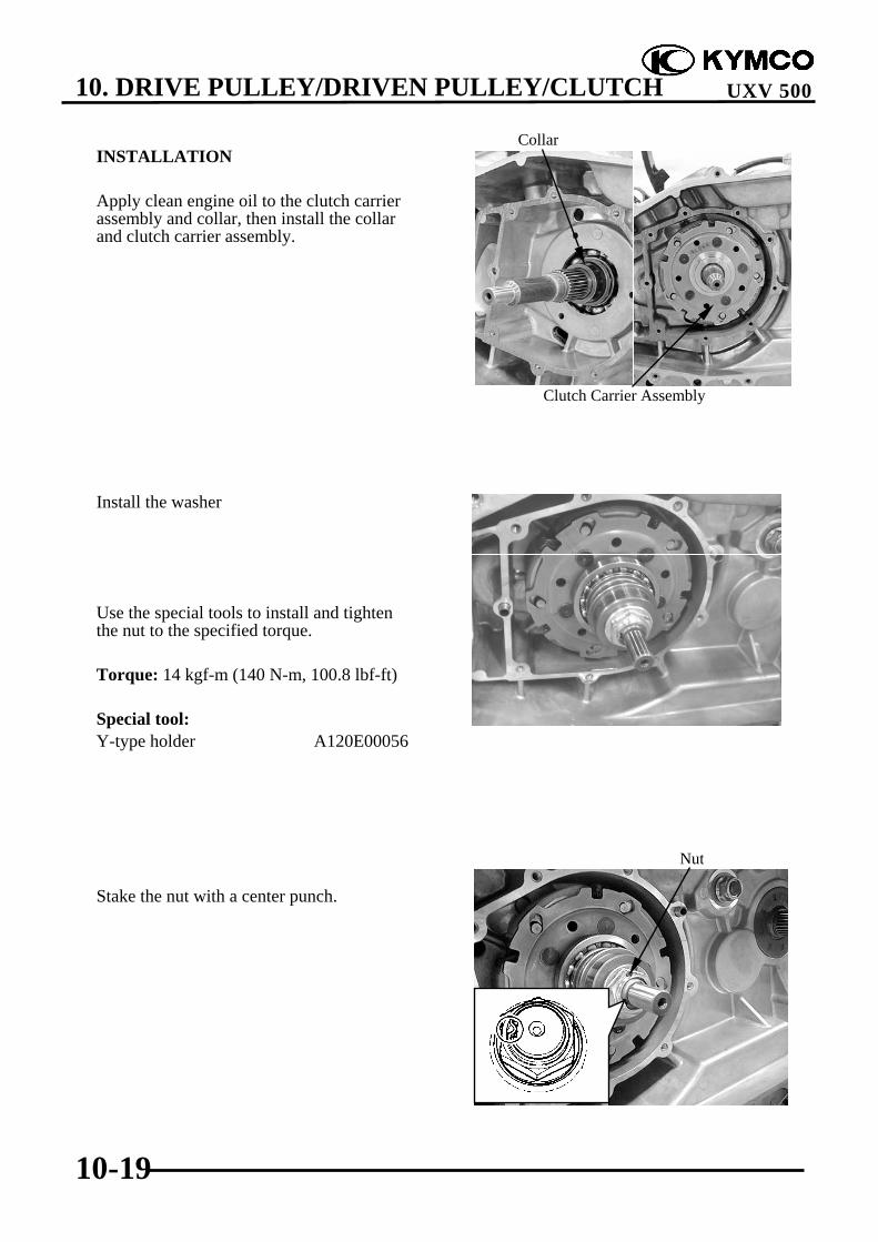
10. DRIVE PULLEY/DRIVEN PULLEY/CLUTCH
10-19
UXV 500
INSTALLATION
Apply clean engine oil to the clutch carrierassembly and collar, then install the collarand clutch carrier assembly.
Install the washer
Use the special tools to install and tightenthe nut to the specified torque.
Torque: 14 kgf-m (140 N-m, 100.8 lbf-ft)
Special tool:Y-type holder A120E00056
Stake the nut with a center punch.
Clutch Carrier Assembly
Collar
Nut

10. DRIVE PULLEY/DRIVEN PULLEY/CLUTCH
10-20
UXV 500
Install the dowel pins and gasket.
Apply molybdenum disulfide grease to theone-way clutch bearing, then install it.Install the clutch housing and tighten thebolts to the specified torque in a crisscrosspattern in 2-3 steps.
Torque: 1 kgf-m (10 N-m, 7.2 lbf-ft)
Gasket Nut/Washer
Dowel Pins
Clutch Housing Assembly
One-way Clutch Bearing

10. DRIVE PULLEY/DRIVEN PULLEY/CLUTCH
10-21
UXV 500
CLUTCHDISASSEMBLY/INSPECTION/ASSEMBLY
DISASSEMBLY
Remove the clutch housing and clutchcarrier assembly (refer to the “CLUTCHREMOVAL/INSTALLATION” section inthis chapter).
Remove the one-way clutch bearing fromthe clutch housing.
Clutch housing removal (not USA type):
Remove the oil seal.Remove the snap ring, then remove theclutch housing.
Remove the snap ring, then remove thebearing.
Snap Ring
Oil Seal
Bearing
Snap Ring
One-way Clutch Bearing

10. DRIVE PULLEY/DRIVEN PULLEY/CLUTCH
10-22
UXV 500
Clutch housing removal (USA type):
Remove the clutch housing.
Remove the oil seal, then remove thebearing.
Clutch Housing
Bearing
Oil Seal
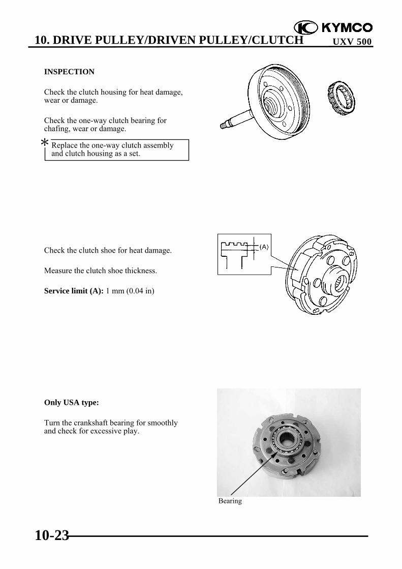
10. DRIVE PULLEY/DRIVEN PULLEY/CLUTCH
10-23
UXV 500
INSPECTION
Check the clutch housing for heat damage,wear or damage.
Check the one-way clutch bearing forchafing, wear or damage.
Check the clutch shoe for heat damage.
Measure the clutch shoe thickness.
Service limit (A): 1 mm (0.04 in)
Only USA type:
Turn the crankshaft bearing for smoothlyand check for excessive play.
Replace the one-way clutch assemblyand clutch housing as a set.
*
Bearing
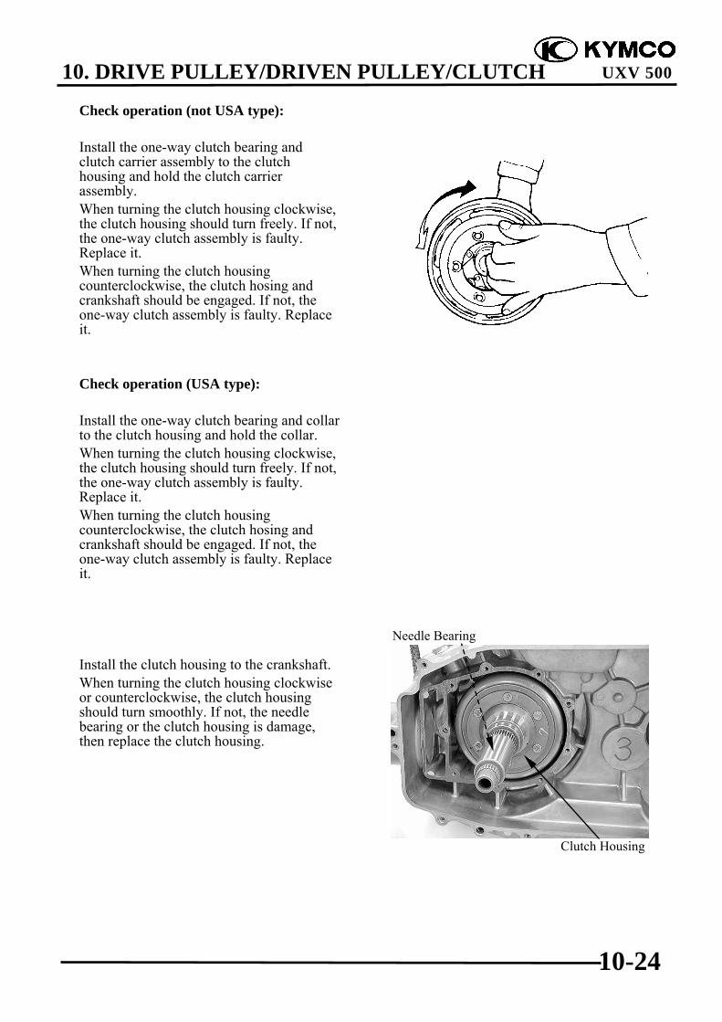
10. DRIVE PULLEY/DRIVEN PULLEY/CLUTCH
10-24
UXV 500
Check operation (not USA type):
Install the one-way clutch bearing andclutch carrier assembly to the clutchhousing and hold the clutch carrierassembly.When turning the clutch housing clockwise,the clutch housing should turn freely. If not,the one-way clutch assembly is faulty.Replace it.When turning the clutch housingcounterclockwise, the clutch hosing andcrankshaft should be engaged. If not, theone-way clutch assembly is faulty. Replaceit.
Check operation (USA type):
Install the one-way clutch bearing and collarto the clutch housing and hold the collar.When turning the clutch housing clockwise,the clutch housing should turn freely. If not,the one-way clutch assembly is faulty.Replace it.When turning the clutch housingcounterclockwise, the clutch hosing andcrankshaft should be engaged. If not, theone-way clutch assembly is faulty. Replaceit.
Install the clutch housing to the crankshaft.When turning the clutch housing clockwiseor counterclockwise, the clutch housingshould turn smoothly. If not, the needlebearing or the clutch housing is damage,then replace the clutch housing.
Clutch Housing
Needle Bearing

10. DRIVE PULLEY/DRIVEN PULLEY/CLUTCH
10-25
UXV 500
ASSEMBLY
Clutch housing installation (not USAtype):
Apply clean engine oil, then install the newbearing.Install the snap ring.
Install the clutch housing.Install the snap ring.Apply lightweight lithium-soap base greaseto the new oil seal lip, then install the newoil seal.
Clutch housing installation (USA type):
Apply clean engine oil, then install the newbearing.
Bearing
Snap Ring
Snap Ring
Oil Seal
Bearing

10. DRIVE PULLEY/DRIVEN PULLEY/CLUTCH
10-26
UXV 500
Apply lightweight lithium-soap base greaseto the new oil seal lip, then install the newoil seal.
Install the clutch housing.
One-way clutch bearing installation:
Install the one-way clutch bearing into theclutch housing.
Oil Seal
Clutch Housing
The one-way clutch bearing should beinstalled in the clutch carrier assemblywith the arrow mark and “OUT SIDE”mark facing toward the clutch carrierassembly.
*

10. DRIVE PULLEY/DRIVEN PULLEY/CLUTCH
10-27
UXV 500
REMOVEL CTV PARTS ON VEHICLEKey Switch “OFF”.Remove the seat, and center cover. cargobed Up then remove the fuel cap.Remove the side panel .R.front andprotector Fuel tank.Remove the tank frame.
Disconnect the fuel tube from fuel pump.
Disconnect the fuel unit connectors.Remove the 4 screws and from the fuel tank,then remove the fuel tank.Remove the CVT cover screws.Disconnect the CVT cover.Remove the CVT parts.
INSTALLATION
Installation is in the reverse order of removal.