Embed Size (px)
Citation preview
GENERAL INFORMATION USER’S MANUAL
Colormetry
CMU-324HE
Hardness
For Europe
Manual Code No. S855-080-5813
This document was formulated in Japan. Comply with the regulations and standards of the country of use regarding installation and usage. The specifications of products and components may vary with country of use and the site situation. INFORMATION IN THIS MANUAL MAY BE CHANGED WITHOUT NOTICE.

Release date: March 2017
Important Safety Information
i
Important Safety Information
Before using the Colormetry CMU-324HE, ensure that this User’s Manual is read and fully
understood; furthermore, the instructions given herein should be strictly observed during
operation.
Failure to use the Colormetry CMU-324HE in the appropriate manner can, therefore, result in
death, injury, the outbreak of fire, and other serious accidents.
In order to ensure that tasks undertaken during operation and maintenance of the Colormetry
CMU-324HE can be completed safely, it is critical that all dangerous and hazardous parts of this
equipment be confirmed in advance. Here at MIURA, it is practically impossible to anticipate all
potentially dangerous situations, and therefore, this User’s Manual deals only with known
hazards. A higher level of safety can be achieved by careful observation of the warnings and
instructions set forth herein.
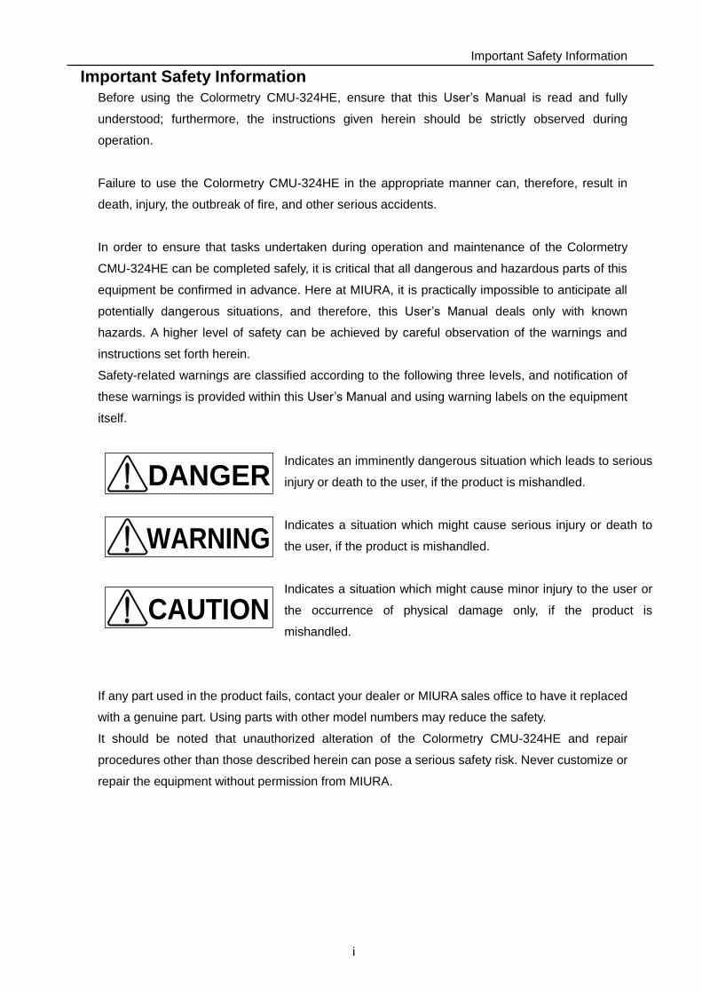
Safety-related warnings are classified according to the following three levels, and notification of
these warnings is provided within this User’s Manual and using warning labels on the equipment
itself.
Indicates an imminently dangerous situation which leads to serious
injury or death to the user, if the product is mishandled.
Indicates a situation which might cause serious injury or death to
the user, if the product is mishandled.
Indicates a situation which might cause minor injury to the user or
the occurrence of physical damage only, if the product is
mishandled.
If any part used in the product fails, contact your dealer or MIURA sales office to have it replaced
with a genuine part. Using parts with other model numbers may reduce the safety.
It should be noted that unauthorized alteration of the Colormetry CMU-324HE and repair
procedures other than those described herein can pose a serious safety risk. Never customize or
repair the equipment without permission from MIURA.
DANGER
WARNING
CAUTION
Introduction
ii
Introduction This document describes the methods of handling the Colormetry CMU-324HE (hereinafter
called “the equipment”) to ensure its proper use.
Not only those who use the equipment for the first time but also those who know the handling
methods should read this document carefully and understand the proper handling methods
before use of the equipment.
Furthermore, we also recommend that this User’s Manual be safely kept in close proximity to the
equipment so that it can be referred to at any time to confirm the correct usage.
Follow the INSTALLATION AND START UP USER’S MANUAL (separate volume) for installing
the equipment.
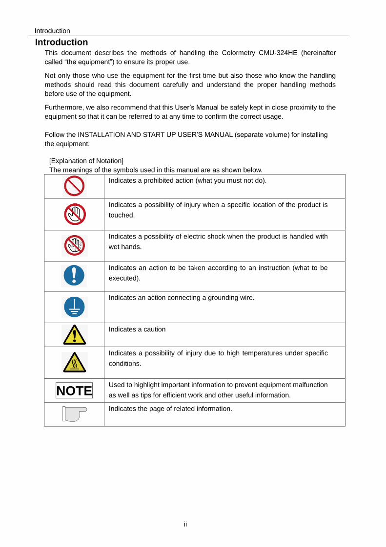
[Explanation of Notation]
The meanings of the symbols used in this manual are as shown below.
Indicates a prohibited action (what you must not do).
Indicates a possibility of injury when a specific location of the product is
touched.
Indicates a possibility of electric shock when the product is handled with
wet hands.
Indicates an action to be taken according to an instruction (what to be
executed).
Indicates an action connecting a grounding wire.
Indicates a caution
Indicates a possibility of injury due to high temperatures under specific
conditions.
NOTE Used to highlight important information to prevent equipment malfunction
as well as tips for efficient work and other useful information.
Indicates the page of related information.
Table of Contents
iii
Table of Contents
Important Safety Information ................................................................. i
Introduction .......................................................................................... ii
SECTION 1 SAFETY .................................................................. 1
1 Safety Regulations ......................................................................... 1
2 Safety-related Knowledge and Expertise ........................................ 2
3 Protective Equipment...................................................................... 2
4 Prohibition of Unapproved Modification .......................................... 2
5 Warning Labels on the Equipment .................................................. 3
6 Safety Precautions ......................................................................... 4
6.1 Installation ................................................................................................ 4
6.2 Safety Precautions ................................................................................... 5
6.3 Pre-operation Inspection (Excerpt from page 21 onwards) ...................... 5
6.4 Inspection and Maintenance (Excerpt from page 37 onwards) ................. 6
6.5 Storage (Excerpt from page 46 onwards) ................................................. 7
SECTION 2 OVERVIEW ............................................................. 8
1 Outline ............................................................................................ 8
1.1 Usage ....................................................................................................... 8
1.2 Purpose .................................................................................................... 8
1.3 System Layout .......................................................................................... 9
1.4 Principle .................................................................................................. 10
1.5 Applicable Water Condition .................................................................... 11
1.6 Highlights of Features ............................................................................. 12
2 Name of Parts............................................................................... 15
2.1 Overall View ........................................................................................... 15
2.2 Reagent Cartridge .................................................................................. 17
2.3 Filter Casing Assembly ........................................................................... 18
3 Specifications ............................................................................... 19
3.1 General Specifications ............................................................................ 19
3.2 Physical Data .......................................................................................... 19
3.3 Monitoring Capabilities ........................................................................... 19
3.4 Feed-water and Drain-water Connection ................................................ 20
3.5 Accessories ............................................................................................ 20
3.6 Consumable parts (Sold separately) ...................................................... 20
Table of Contents
iv
SECTION 3 PRE-OPARATION INSPECTION .......................... 21
1 Inspections and Preparations before Start up .............................. 21
1.1 Inspection and Preparation of the Surrounding Area Peripheral
Equipment .............................................................................................. 21
2 Preparations before Start up ........................................................ 22
SECTION 4 OPERATION .......................................................... 23
1 Operation ..................................................................................... 23
1.1 Self Check Mode .................................................................................... 23
1.2 Automatic Monitoring .............................................................................. 24
1.3 Manual Monitoring .................................................................................. 24
2 FUNCTIONS ................................................................................ 25
2.1 Remote Signal Input ............................................................................... 25
2.1.1 Method .............................................................................................................. 25
2.1.2 Detailed descriptions ........................................................................................ 25
2.1.3 Delay time of remote signals ............................................................................ 27
2.2 Colormetry Monitor Timing ...................................................................... 28
2.2.1 Automatic monitoring ........................................................................................ 28
2.2.2 Manual monitoring ............................................................................................ 30
2.3 Concentration Evaluation ........................................................................ 31
2.3.1 Manual monitor ................................................................................................. 31
2.3.2 Concentration anomaly .................................................................................... 32
SECTION 5 INSPECTION AND MAINTENANCE .................... 37
1 Reagent Cartridge ........................................................................ 37
1.1 Reagent Cartridge Replacement Timing ................................................. 37
1.2 Cautions for Handling ............................................................................. 37
1.3 Reagent Cartridge Replacement Method ............................................... 38
2 Fiber Filter and Constant Flow Valve Replacement ...................... 39
2.1 Fiber Filter Replacement Timing ............................................................. 39
2.2 Fiber Filter Replacement ........................................................................ 39
2.2.1 Remove filter casing assembly ........................................................................ 39
2.2.2 Fiber filter replacement..................................................................................... 40
2.2.3 Filter case assembly installation ...................................................................... 41
3 Daily Inspection ............................................................................ 42
3.1 Inspection Item ....................................................................................... 42
3.1.1 Monitor operation ............................................................................................. 42
3.1.2 Feed-water and drain-water tube ..................................................................... 42
3.1.3 Filter case assembly ......................................................................................... 43
3.2 Others ..................................................................................................... 43
Table of Contents
v
SECTION 6 BREAKDOWN AND COUNTERMEASURES ...... 44
1 Self Check Function ..................................................................... 44
1.1 Display .................................................................................................... 44
1.2 Alarm ...................................................................................................... 44
1.3 Alarm Reset ............................................................................................ 44
2 Self Check Items .......................................................................... 45
SECTION 7 STORAGE ............................................................. 46
1 Extended Inactivity ....................................................................... 46
2 Transfer or Resale ........................................................................ 46
3 Export ........................................................................................... 46
SECTION 8 DISPOSAL ............................................................ 47
1 Disposal ........................................................................................ 47
SECTION 9 WARRANTY .......................................................... 48
1 Note Regarding Warranty ............................................................. 48
2 Questions Regarding the Product and User’s Manual .................. 48
3 If the Operation Manual is Lost ..................................................... 48
SECTION 1 SAFETY
1
SECTION 1 SAFETY
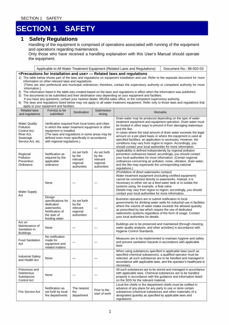
1 Safety Regulations Handling of the equipment is comprised of operations associated with running of the equipment and operations regarding maintenance. Only those who have received a handling explanation with this User’s Manual should operate the equipment.
Applicable to All Water Treatment Equipment (Related Laws and Regulations) Document No.: 98-002-03
<Precautions for installation and use> — Related laws and regulations 1) The table below shows part of the laws and regulations on equipment installation and use. Refer to the separate document for more
information on other relevant laws and regulations. (There are also prefectural and municipal ordinances; therefore, contact the supervisory authority or competent authority for more information.)
2) The information listed in the table was created based on the laws and regulations in effect when the information was published. 3) The documents to be submitted and their destination vary depending on your equipment and facilities.
If you have any questions, contact your nearest dealer, MIURA sales office, or the competent supervisory authority. 4) The laws and regulations listed below may not apply to all water treatment equipment. Refer only to those laws and regulations that
apply to your equipment and facilities.
Related laws and regulations
Form(s) to be submitted
Destination Submission
timing Remarks
Water Quality Pollution Control Act, River Act, Sewerage Service Act, etc.
Verification required from local towns and cities in which the water treatment equipment or other equipment is installed. (The laws and regulations in some areas may be defined even more specifically in accordance with regional regulations.)
Drain water may be produced depending on the type of water treatment equipment and equipment operation. Drain water must be treated in other ways to prevent it from damaging waterways and the like. In cases where the total amount of drain water exceeds the legal amount on a per-plant basis or where the equipment is used at specified facilities, an application is necessary. However, the conditions may vary from region to region. Accordingly, you should contact your local authorities for more information.
Regional Pollution Prevention Ordinance
Notification as required by the applicable ordinance
As set forth by the relevant regional authorities
As set forth by the relevant regional authorities
Applicability is defined independently by regional pollution prevention ordinances based; accordingly, you should contact your local authorities for more information. (Certain regional ordinances concerning air pollution, noise, vibration, drain water, and the like may supersede the corresponding national regulations.)
Water Supply Act
None — —
(Prohibition of direct waterworks contact) Water treatment equipment (excluding certified equipment) cannot be connected directly to waterworks. Instead, it is necessary to either set up a feed water tank or to isolate the systems using, for example, a float valve. Details may vary from region to region; accordingly, you should contact your local authorities for more information.
Design specifications for dedicated waterworks, Notification of the start of feeding water
As set forth by the relevant regional authorities
—
Business operators are to submit notification to local governments for drinking water wells for industrial use in facilities where the volume of water intake exceeds the allowed quantity as prescribed by law which require the use of dedicated waterworks systems regardless of the form of usage. Contact your local authorities for details.
Act on Maintenance of Sanitation in Buildings
None — — Buildings are to be preserved and maintained (through cleaning, water quality analysis, and other activities) in accordance with Hygiene Control Standards.
Food Sanitation Act
No notification made for equipment and related matters
— — Measures are to be implemented to maintain hygiene and safety and prevent sanitation hazards in accordance with applicable laws.
Industrial Safety and Health Act
None — —
When using substances specified in applicable laws (such as specified chemical substances), a qualified operator must be selected, all such substances are to be handled and managed in accordance with applicable laws, and the operator’s healthcare is necessary.
Poisonous and Deleterious Substances Control Act
None — —
All such substances are to be stored and managed in accordance with applicable laws. Chemical substances are to be handled properly in accordance with the guidance and information listed on the SDS for the relevant material.
Fire Service Act Notification as set forth by local fire departments
The nearest fire department
Prior to the start of work
Local fire chiefs or fire department chiefs must be notified in advance of any plans for any party to use or store certain substances (chemical substances and other materials) of a designated quantity as specified by applicable laws and regulations.
SECTION 1 SAFETY
2
2 Safety-related Knowledge and Expertise Usage of the equipment requires knowledge and experience of the operation and maintenance
of mechanical equipment.
In addition, only the following persons should be permitted to perform work on the equipment.
・Operators who have read and fully understood this User’s Manual.
3 Protective Equipment
Wear protective items such as a helmet, safety glasses, a safety mask, safety footwear, and
leather gloves as necessary for the task in hand.
4 Prohibition of Unapproved Modification
Customization or modification not recommended by MIURA may present safety problems and is
therefore prohibited. If you wish to modify your water treatment equipment, contact your dealer
or MIURA sales office in advance. It should be noted that MIURA will accept no responsibility for
the outcome of unapproved customization.
SECTION 1 SAFETY
3
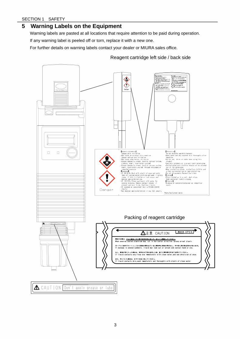
5 Warning Labels on the Equipment
Warning labels are pasted at all locations that require attention to be paid during operation.
If any warning label is peeled off or torn, replace it with a new one.
For further details on warning labels contact your dealer or MIURA sales office.
Packing of reagent cartridge
Reagent cartridge left side / back side
SECTION 1 SAFETY
4
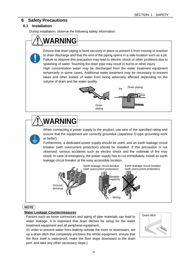
Ensure that drain piping is fixed securely in place to prevent it from moving in reaction
to drain discharge and that the end of the piping opens in a safe location such as a pit.
Failure to observe this precaution may lead to electric shock or other problems due to
splashing of water. Touching the drain pipe may result in burns or other injury.
High concentration water may be discharged from the water treatment equipment
temporarily in some cases. Additional water treatment may be necessary to prevent
lakes and other bodies of water from being adversely affected depending on the
volume of drain and the water quality.
When connecting a power supply to the product, use wire of the specified rating and
ensure that the equipment are correctly grounded (Japanese D-type grounding work
or better).
Furthermore, a dedicated power supply should be used, and an earth leakage circuit
breaker (with overcurrent protection) should be installed. If this precaution is not
observed, serious accidents such as electric shock and the outbreak of fire may
result. In case of emergency, the power supply has to cut immediately. Install an earth
leakage circuit breaker at the easy accessible location.
6 Safety Precautions
6.1 Installation
During installation, observe the following safety information.
NOTE
Water Leakage Countermeasures
Factors such as loose connectors and aging of pipe materials can lead to
water leakage. It is important that drain ditches be setup for the water
treatment equipment and all peripheral equipment.
(In order to prevent water from leaking outside the room or downstairs, set
up a drain ditch that completely encloses the whole equipment, ensure that
the floor itself is waterproof, make the floor slope downward to the drain
port, and take any other necessary steps.)
Drain ditch
WARNING
Drain piping
Pit Drain piping
WARNING
Ground terminal
Breaker capacity
Earth leakage circuit breaker (with overcurrent protection)
Wiring
Earth leakage circuit breaker (with overcurrent protection)
SECTION 1 SAFETY
5
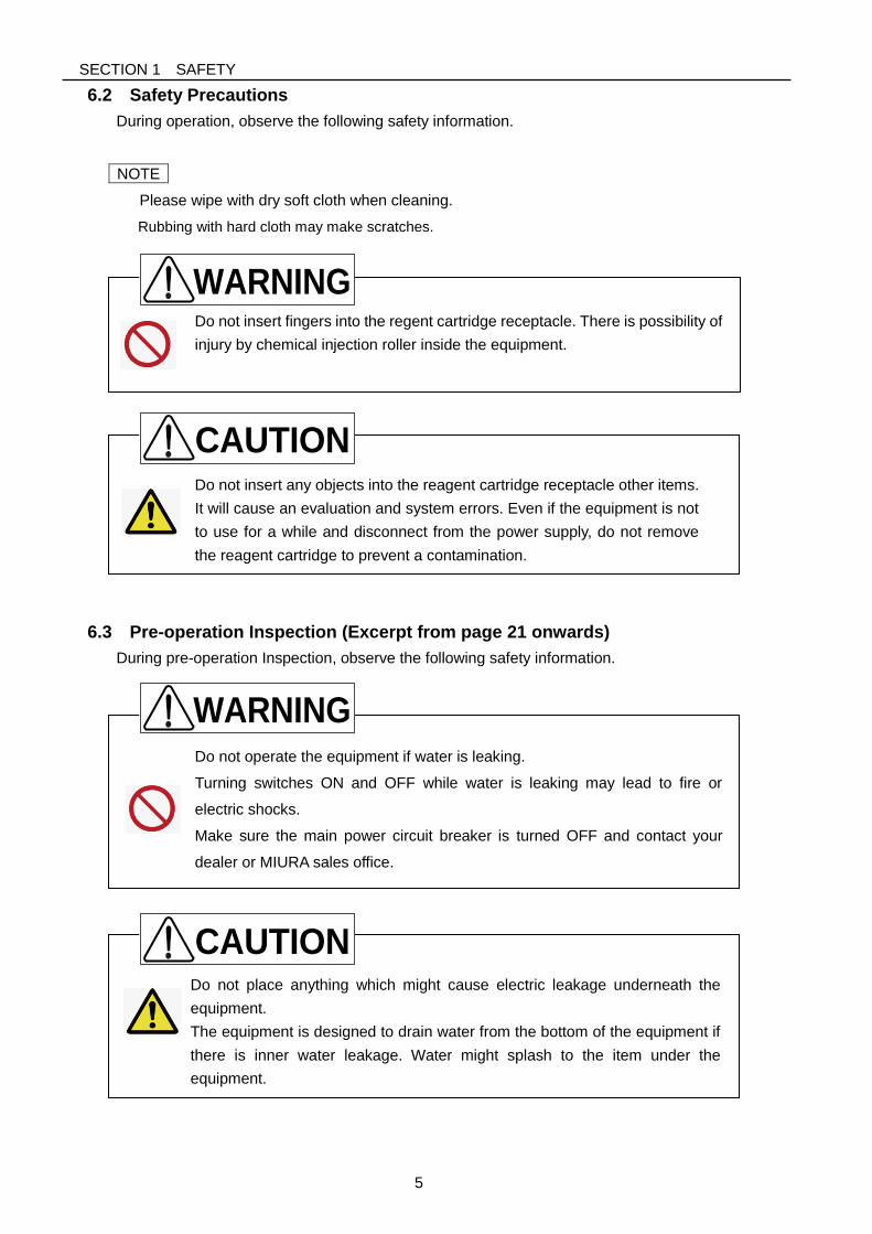
Do not place anything which might cause electric leakage underneath the
equipment.
The equipment is designed to drain water from the bottom of the equipment if
there is inner water leakage. Water might splash to the item under the
equipment.
Do not insert any objects into the reagent cartridge receptacle other items.
It will cause an evaluation and system errors. Even if the equipment is not
to use for a while and disconnect from the power supply, do not remove
the reagent cartridge to prevent a contamination.
Do not insert fingers into the regent cartridge receptacle. There is possibility of
injury by chemical injection roller inside the equipment.
Do not operate the equipment if water is leaking.
Turning switches ON and OFF while water is leaking may lead to fire or
electric shocks.
Make sure the main power circuit breaker is turned OFF and contact your
dealer or MIURA sales office.
6.2 Safety Precautions
During operation, observe the following safety information.
NOTE
Please wipe with dry soft cloth when cleaning.
Rubbing with hard cloth may make scratches.
6.3 Pre-operation Inspection (Excerpt from page 21 onwards)
During pre-operation Inspection, observe the following safety information.
WARNING
WARNING
CAUTION
CAUTION
SECTION 1 SAFETY
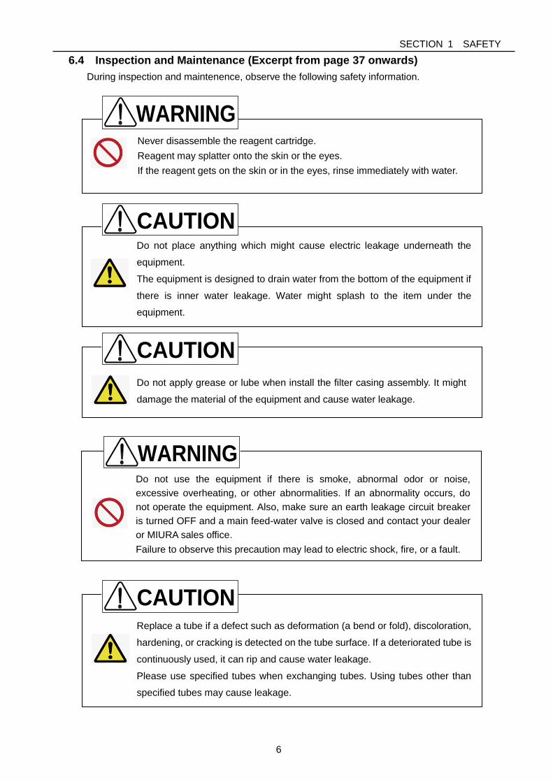
6
Replace a tube if a defect such as deformation (a bend or fold), discoloration,
hardening, or cracking is detected on the tube surface. If a deteriorated tube is
continuously used, it can rip and cause water leakage.
Please use specified tubes when exchanging tubes. Using tubes other than
specified tubes may cause leakage.
Do not apply grease or lube when install the filter casing assembly. It might
damage the material of the equipment and cause water leakage.
Never disassemble the reagent cartridge.
Reagent may splatter onto the skin or the eyes.
If the reagent gets on the skin or in the eyes, rinse immediately with water.
Do not place anything which might cause electric leakage underneath the
equipment.
The equipment is designed to drain water from the bottom of the equipment if
there is inner water leakage. Water might splash to the item under the
equipment.
Do not use the equipment if there is smoke, abnormal odor or noise,
excessive overheating, or other abnormalities. If an abnormality occurs, do
not operate the equipment. Also, make sure an earth leakage circuit breaker
is turned OFF and a main feed-water valve is closed and contact your dealer
or MIURA sales office.
Failure to observe this precaution may lead to electric shock, fire, or a fault.
6.4 Inspection and Maintenance (Excerpt from page 37 onwards)
During inspection and maintenence, observe the following safety information.
CAUTION
WARNING
WARNING
CAUTION
CAUTION
SECTION 1 SAFETY
7
Do not perform any unapproved installation work or connect any peripheral
equipment.
Failure to observe this precaution may lead to personal injuries.
If there is a defect or cracking on the filter casing assembly, turn OFF an earth
leakage circuit breaker and close a main feed-water valve. Then, replace the
If water leakage is not stopped even though tightening the filter casing
assembly and tube joint, replace the filter casing assembly.
6.5 Storage (Excerpt from page 46 onwards)
During storage, observe the following safety information.
WARNING
CAUTION
SECTION 2 OVERVIEW
8
SECTION 2 OVERVIEW
1 Outline
1.1 Usage
Basically, the Colormetry CMU-324HE has been developed as part of a processing system for
boiler water.
The Colormetry automatically and regularly implements the process of sampling the water,
injecting the reagent, stirring and evaluating the result, thereby obviating the conventional
manual procedure.
The equipment has been designed with emphasis on the reliability of the monitoring results.
The manually selectable conditions—for instance, to verify monitoring upon the detection of
hardness leakage—prevent temporary fluctuations from triggering alarms.
1.2 Purpose
The Colormetry CMU-324HE is a device for monitoring water quality. It is not a device for
measuring. The result data cannot be used for inspection or analysis of the water treatment
system.
Usage example:
Monitoring hardness leakage of the water softener
SECTION 2 OVERVIEW
9
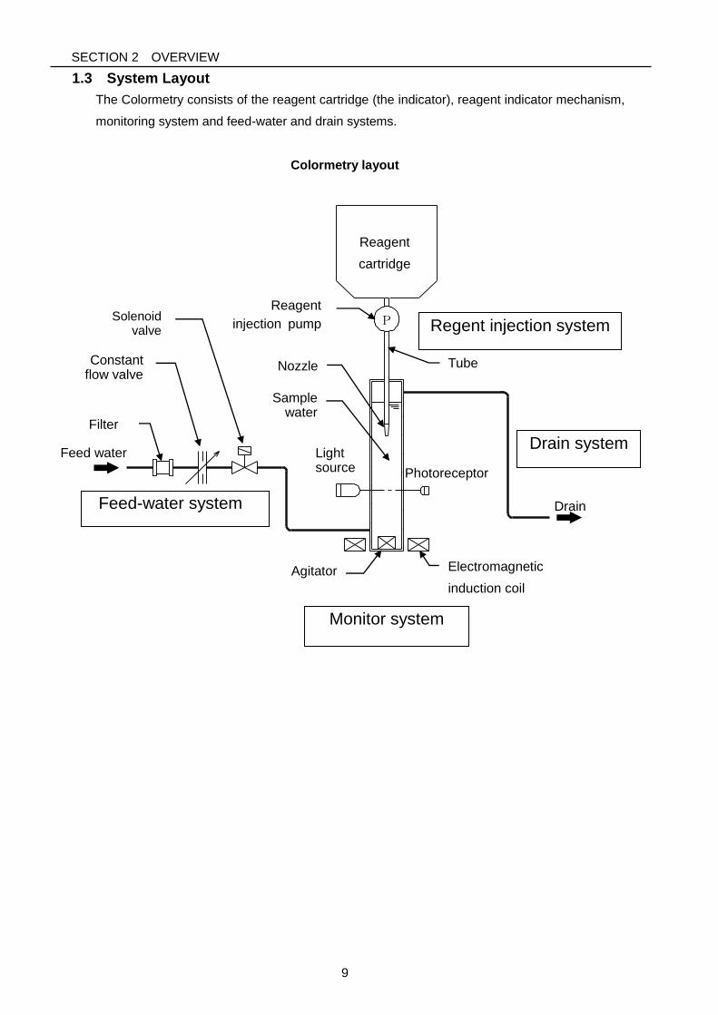
1.3 System Layout
The Colormetry consists of the reagent cartridge (the indicator), reagent indicator mechanism,
monitoring system and feed-water and drain systems.
Colormetry layout
P
Photoreceptor
Monitor system
Constant flow valve
Solenoid valve
Reagent
cartridge
Light source
Drain
Regent injection system
Drain system
Feed-water system
Tube
Electromagnetic
induction coil
Agitator
Filter
Nozzle
Sample water
Feed water
Reagent
injection pump
SECTION 2 OVERVIEW
10
1.4 Principle
The Colormetry is a device to monitor ionic concentrations in water by applying colorimetric
analysis. In a colorimetric analysis process the ionic and other concentration in water is
monitored by allowing a reagent to react against the target ions and others, and monitoring the
transmissivity of the resultant coloration for light of a specific wavelength. The Colormetry
replaces this process by an electrical monitoring system and automates the entire process.
Other features include the remote alarm output, self check function, and display, as well as the
monitor standby while the water softener is regeneration or the sample water stopped (remote
signal input).
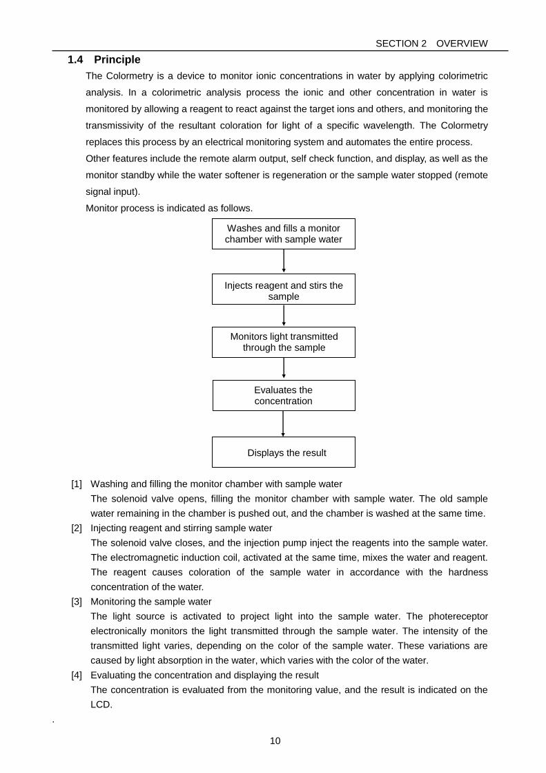
Monitor process is indicated as follows.
[1] Washing and filling the monitor chamber with sample water
The solenoid valve opens, filling the monitor chamber with sample water. The old sample
water remaining in the chamber is pushed out, and the chamber is washed at the same time.
[2] Injecting reagent and stirring sample water
The solenoid valve closes, and the injection pump inject the reagents into the sample water.
The electromagnetic induction coil, activated at the same time, mixes the water and reagent.
The reagent causes coloration of the sample water in accordance with the hardness
concentration of the water.
[3] Monitoring the sample water
The light source is activated to project light into the sample water. The photereceptor
electronically monitors the light transmitted through the sample water. The intensity of the
transmitted light varies, depending on the color of the sample water. These variations are
caused by light absorption in the water, which varies with the color of the water.
[4] Evaluating the concentration and displaying the result
The concentration is evaluated from the monitoring value, and the result is indicated on the
LCD.
.
Displays the result
Washes and fills a monitor chamber with sample water
Injects reagent and stirs the sample
Monitors light transmitted
through the sample
Evaluates the concentration
SECTION 2 OVERVIEW
11
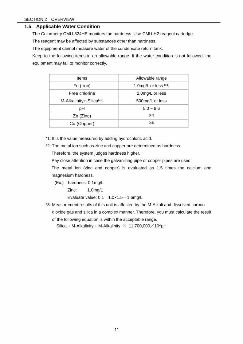
1.5 Applicable Water Condition
The Colormetry CMU-324HE monitors the hardness. Use CMU-H2 reagent cartridge.
The reagent may be affected by substances other than hardness.
The equipment cannot measure water of the condensate return tank.
Keep to the following items in an allowable range. If the water condition is not followed, the
equipment may fail to monitor correctly.
Items Allowable range
Fe (Iron) 1.0mg/L or less (*1)
Free chlorine 2.0mg/L or less
M-Alkalinity+ Silica(*3) 500mg/L or less
pH 5.0 ~ 8.6
Zn (Zinc) (*2)
Cu (Copper) (*2)
*1: It is the value measured by adding hydrochloric acid.
*2: The metal ion such as zinc and copper are determined as hardness.
Therefore, the system judges hardness higher.
Pay close attention in case the galvanizing pipe or copper pipes are used.
The metal ion (zinc and copper) is evaluated as 1.5 times the calcium and
magnesium hardness.
(Ex.) hardness: 0.1mg/L
Zinc: 1.0mg/L
Evaluate value: 0.1+1.0×1.5=1.6mg/L
*3: Measurement results of this unit is affected by the M-Alkali and dissolved carbon
dioxide gas and silica in a complex manner. Therefore, you must calculate the result
of the following equation is within the acceptable range.
Silica + M-Alkalinity + M-Alkalinity × 11,700,000/10^pH
SECTION 2 OVERVIEW
12
1.6 Highlights of Features
The Colormetry has the following features:
[1] Monitors hardness leakage automatically
The monitoring process is fully automated, saving a significant amount of work by
eliminating the need for complicated manual procedures.
[2] Requires no periodic calibration
The equipment needs no cumbersome periodic calibrations.
[3] Includes built-in timer
Monitoring period may be set as desired. (e.g. daily between 9 a.m. and 5 p.m.)
Interval for each monitoring may set as desired. (The interval is selectable in 30-minute
increments between 30 and 240 minutes.)
[4] Alarm set point for the hardness leakage
The evaluation ranges are 0mg/L, 1mg/L, 2mg/L, 3mg/L, 5mg/L and up.
[5] Evaluates hardness leakage at higher accuracy
When a hardness leakage is detected, monitoring is repeated a number of times
(concentration anomaly retry; selectable between 1 and 3 times) to prevent a temporary
fluctuation from triggering an alarm. In addition, such an abnormality must be repeated in a
series of monitoring at a preset interval for a number of times (response alarm cycle; also
selectable between 1 and 8 times). When all of these monitoring results indicate a hardness
leakage, it is evaluated that hardness leakage exists and the alarm is issued.
[6] Indicates data on the display screen
The display indicates the evaluated result, and the major cause of system error occurs in
the equipment.
[7] Offers an alarm function
When it is evaluated that there is a hardness leakage, the buzzer sounds. By the remote
alarm output, the alarm signal can be transmitted to a remote location.
Offers a self check function. If a system error occurs in the equipment, a typical cause will
be displayed in the same manner as the hardness leakage
[8] Stores records of hardness leakage
The equipment stores the records of occurrence date and time, evaluated result and
recovery date and time for each of the 5 latest incidents of hardness leakage. The records
may be utilized to analyze the causes of hardness leakage.
SECTION 2 OVERVIEW
13
[9] Requires minimal maintenance
The reagent cartridge may be replaced using a one-touch action. The reagent cartridge
needs no replacement for approximately 4 months in typical applications. (Note that more
frequent replacement may be necessary, depending on the application.)
[10] Compact in design, easy to install
The main equipment is installed easily on a wall.
Installation is a simple process.
[11] About advanced features
・Remote signal input function
The external signal controls whether to perform monitoring or not. This enables to
remotely stop monitoring while the system, which the water softener is regenerating.
・Remote alarm output
The remote alarm output, the alarm signal can be transmitted to a remote location as a
contact output in case that hardness leakage or system error occurs in the equipment.
・Regent cartridge exchange output
This output may be used to transmit to a remote location when a reagent cartridge
needs to be replaced.
SECTION 2 OVERVIEW
14
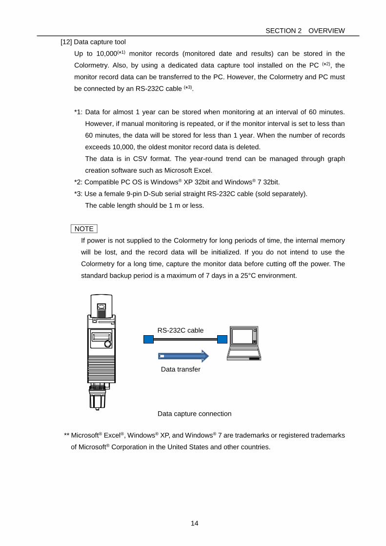
[12] Data capture tool
Up to 10,000(*1) monitor records (monitored date and results) can be stored in the
Colormetry. Also, by using a dedicated data capture tool installed on the PC (*2), the
monitor record data can be transferred to the PC. However, the Colormetry and PC must
be connected by an RS-232C cable (*3).
*1: Data for almost 1 year can be stored when monitoring at an interval of 60 minutes.
However, if manual monitoring is repeated, or if the monitor interval is set to less than
60 minutes, the data will be stored for less than 1 year. When the number of records
exceeds 10,000, the oldest monitor record data is deleted.
The data is in CSV format. The year-round trend can be managed through graph
creation software such as Microsoft Excel.
*2: Compatible PC OS is Windows® XP 32bit and Windows® 7 32bit.
*3: Use a female 9-pin D-Sub serial straight RS-232C cable (sold separately).
The cable length should be 1 m or less.
NOTE
If power is not supplied to the Colormetry for long periods of time, the internal memory
will be lost, and the record data will be initialized. If you do not intend to use the
Colormetry for a long time, capture the monitor data before cutting off the power. The
standard backup period is a maximum of 7 days in a 25°C environment.
Data capture connection
** Microsoft® Excel®, Windows® XP, and Windows® 7 are trademarks or registered trademarks
of Microsoft® Corporation in the United States and other countries.
RS-232C cable
Data transfer
SECTION 2 OVERVIEW
15
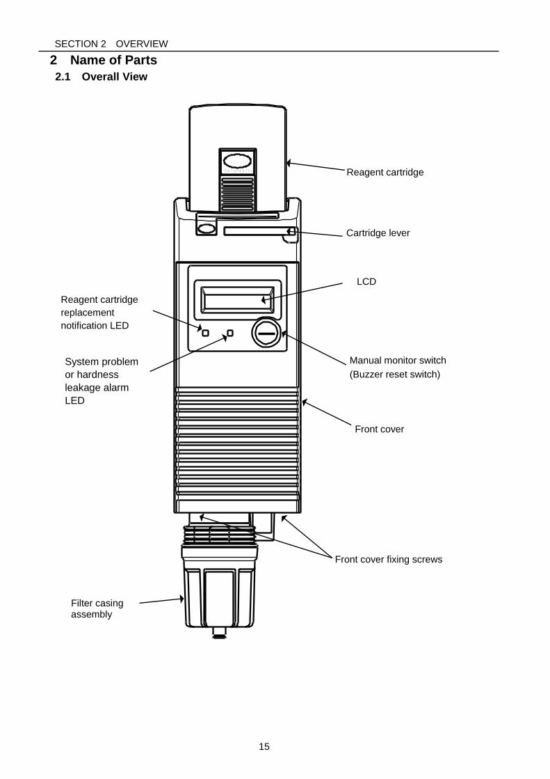
2 Name of Parts
2.1 Overall View
Manual monitor switch
(Buzzer reset switch)
LCD
displa
y
Cartridge lever
Reagent cartridge
Front cover
Filter casing assembly
Front cover fixing screws
System problem
or hardness
leakage alarm
LED
Reagent cartridge
replacement
notification LED
SECTION 2 OVERVIEW
16
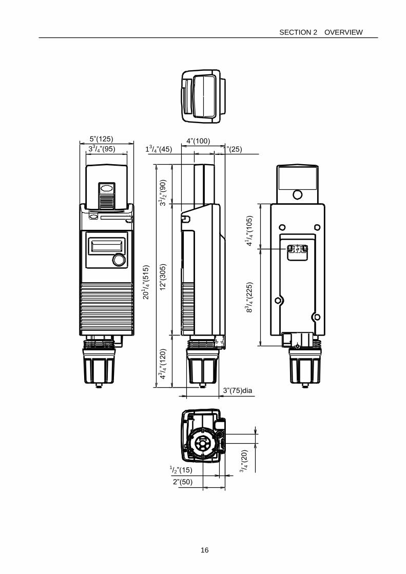
5”(125)
33/4”(95)
4”(100) 1”(25) 1
3/4”(45)
3”(75)dia
1/2”(15)
2”(50)
43/ 4
”(120)
12”(
305)
31/ 2
”(90)
2
01/ 4
”(515)
83/ 4
”(225)
41/ 4
”(105)
3/ 4
”(20)
SECTION 2 OVERVIEW
17
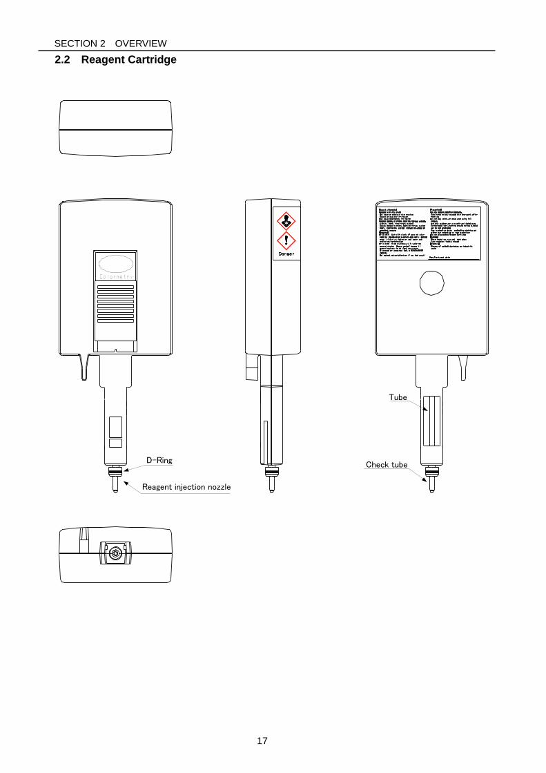
2.2 Reagent Cartridge
Reagent injection nozzle
D-Ring
Tube
Check tube
SECTION 2 OVERVIEW
18
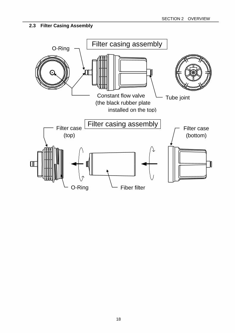
2.3 Filter Casing Assembly
Filter casing assembly
Filter casing assembly
Tube joint Constant flow valve
(the black rubber plate
installed on the top)
O-Ring
Filter case
(top)
O-Ring Fiber filter
Filter case
(bottom)
SECTION 2 OVERVIEW
19
3 Specifications
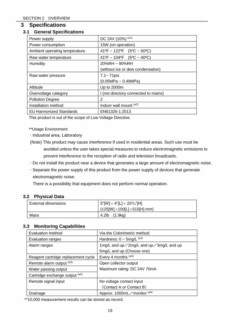
3.1 General Specifications
Power supply DC 24V (10%) (*1)
Power consumption 15W (on operation)
Ambient operating temperature 41ºF ~ 122ºF (5ºC ~ 50ºC)
Raw water temperature 41ºF ~ 104ºF (5ºC ~ 40ºC)
Humidity 20%RH ~ 90%RH
(without ice or dew condensation)
Raw water pressure 7.1~ 71psi
(0.05MPa ~ 0.49MPa)
Altitude Up to 2000m
Overvoltage category I (not directory connected to mains)
Pollution Degree 2
Installation method Indoor wall mount (*2)
EU Harmonized Standards EN61326-1:2013
This product is out of the scope of Low Voltage Directive.
**Usage Environment
Industrial area, Laboratory
(Note) This product may cause interference if used in residential areas. Such use must be
avoided unless the user takes special measures to reduce electromagnetic emissions to
prevent interference to the reception of radio and television broadcasts.
Do not install the product near a device that generates a large amount of electromagnetic noise.
Separate the power supply of this product from the power supply of devices that generate
electromagnetic noise.
There is a possibility that equipment does not perform normal operation.
3.2 Physical Data
External dimensions 5”[W] 4”[L] 201/4”[H]
(125[W] 100[L] 515[H] mm)
Mass 4.2lb (1.9kg)
3.3 Monitoring Capabilities
Evaluation method Via the Colorimetric method
Evaluation ranges Hardness: 0 ~ 5mg/L (*3)
Alarm ranges 1mg/L and up/2mg/L and up/3mg/L and up
5mg/L and up (Choose one)
Reagent cartridge replacement cycle Every 4 months (*4)
Remote alarm output (*5) Open collector output
Maximum rating: DC 24V 70mA Water passing output
Cartridge exchange output (*5)
Remote signal input No voltage contact input
(Contact A or Contact B)
Drainage Approx. 1000mL/monitor (*6)
**10,000 measurement results can be stored as record.
SECTION 2 OVERVIEW
20
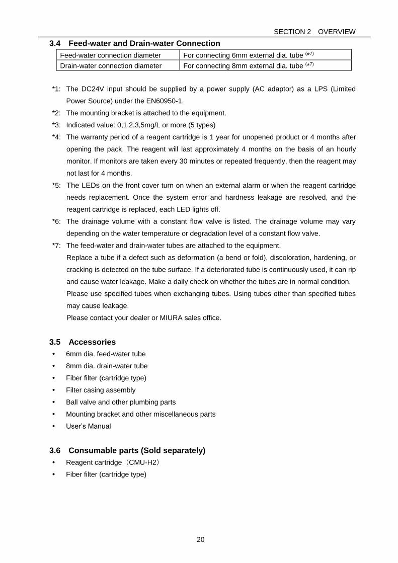
3.4 Feed-water and Drain-water Connection
Feed-water connection diameter For connecting 6mm external dia. tube (*7)
Drain-water connection diameter For connecting 8mm external dia. tube (*7)
*1: The DC24V input should be supplied by a power supply (AC adaptor) as a LPS (Limited
Power Source) under the EN60950-1.
*2: The mounting bracket is attached to the equipment.
*3: Indicated value: 0,1,2,3,5mg/L or more (5 types)
*4: The warranty period of a reagent cartridge is 1 year for unopened product or 4 months after
opening the pack. The reagent will last approximately 4 months on the basis of an hourly
monitor. If monitors are taken every 30 minutes or repeated frequently, then the reagent may
not last for 4 months.
*5: The LEDs on the front cover turn on when an external alarm or when the reagent cartridge
needs replacement. Once the system error and hardness leakage are resolved, and the
reagent cartridge is replaced, each LED lights off.
*6: The drainage volume with a constant flow valve is listed. The drainage volume may vary
depending on the water temperature or degradation level of a constant flow valve.
*7: The feed-water and drain-water tubes are attached to the equipment.
Replace a tube if a defect such as deformation (a bend or fold), discoloration, hardening, or
cracking is detected on the tube surface. If a deteriorated tube is continuously used, it can rip
and cause water leakage. Make a daily check on whether the tubes are in normal condition.
Please use specified tubes when exchanging tubes. Using tubes other than specified tubes
may cause leakage.
Please contact your dealer or MIURA sales office.
3.5 Accessories
6mm dia. feed-water tube
8mm dia. drain-water tube
Fiber filter (cartridge type)
Filter casing assembly
Ball valve and other plumbing parts
Mounting bracket and other miscellaneous parts
User’s Manual
3.6 Consumable parts (Sold separately)
Reagent cartridge(CMU-H2)
Fiber filter (cartridge type)
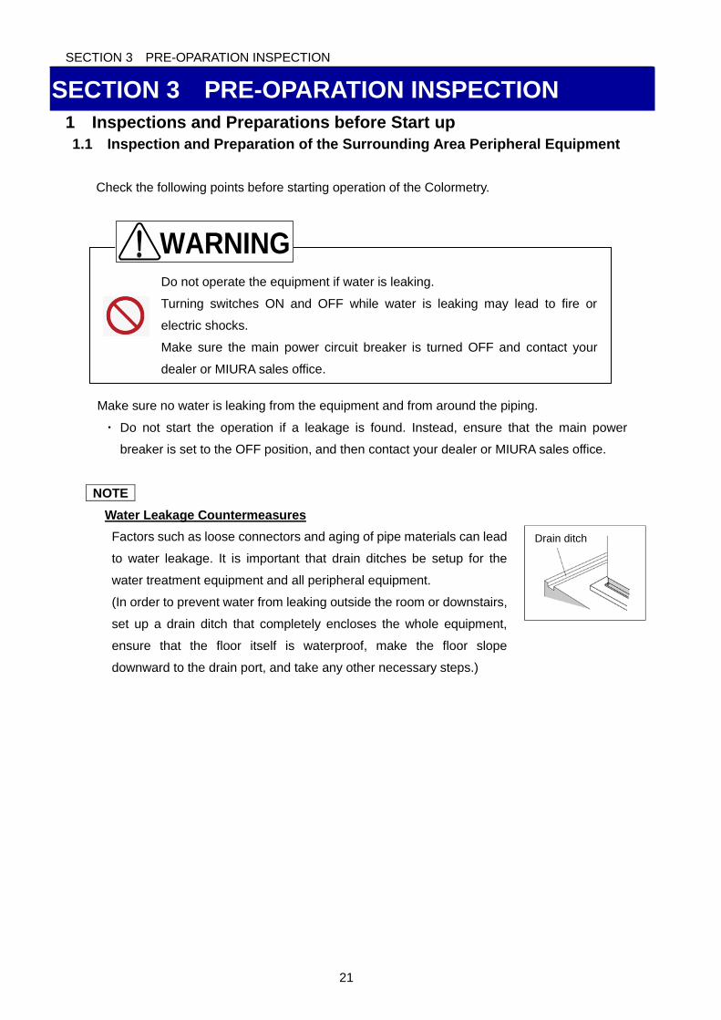
SECTION 3 PRE-OPARATION INSPECTION
21
Do not operate the equipment if water is leaking.
Turning switches ON and OFF while water is leaking may lead to fire or
electric shocks.
Make sure the main power circuit breaker is turned OFF and contact your
dealer or MIURA sales office.
SECTION 3 PRE-OPARATION INSPECTION
1 Inspections and Preparations before Start up
1.1 Inspection and Preparation of the Surrounding Area Peripheral Equipment
Check the following points before starting operation of the Colormetry.
Make sure no water is leaking from the equipment and from around the piping.
・ Do not start the operation if a leakage is found. Instead, ensure that the main power
breaker is set to the OFF position, and then contact your dealer or MIURA sales office.
NOTE
Water Leakage Countermeasures
Factors such as loose connectors and aging of pipe materials can lead
to water leakage. It is important that drain ditches be setup for the
water treatment equipment and all peripheral equipment.
(In order to prevent water from leaking outside the room or downstairs,
set up a drain ditch that completely encloses the whole equipment,
ensure that the floor itself is waterproof, make the floor slope
downward to the drain port, and take any other necessary steps.)
WARNING
Drain ditch
SECTION 3 PRE-OPARATION INSPECTION
22
Do not place anything which might cause electric leakage underneath the
equipment.
The equipment is designed to drain water from the bottom of the equipment if
there is inner water leakage. Water might splash to the item under the
equipment.
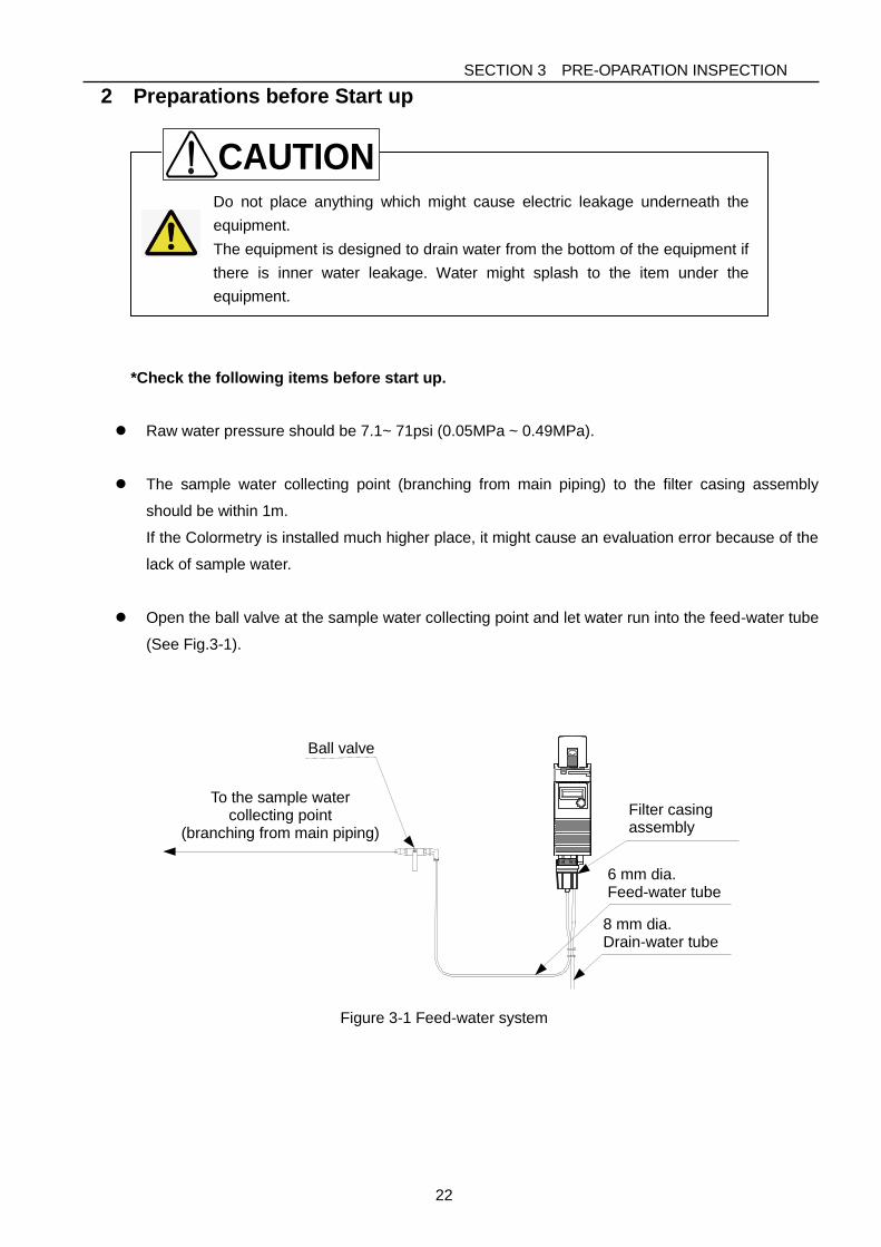
2 Preparations before Start up
*Check the following items before start up.
Raw water pressure should be 7.1~ 71psi (0.05MPa ~ 0.49MPa).
The sample water collecting point (branching from main piping) to the filter casing assembly
should be within 1m.
If the Colormetry is installed much higher place, it might cause an evaluation error because of the
lack of sample water.
Open the ball valve at the sample water collecting point and let water run into the feed-water tube
(See Fig.3-1).
To the sample water collecting point
(branching from main piping)
Ball valve
6 mm dia. Feed-water tube
Filter casing assembly
8 mm dia. Drain-water tube
Figure 3-1 Feed-water system
CAUTION
SECTION 4 OPERATION
23
SECTION 4 OPERATION
1 Operation
1.1 Self Check Mode
When supply the power to the equipment, the self check starts automatically.
・If the equipment is working correctly, the self check completes in about 2 minutes.
・At its completion of the self check, the buzzer sounds 4 times and monitoring starts.
●Remote signal
When the remote signal is utilized, the equipment keeps in standby until the remote signal
permits monitoring.
●System error
If the equipment is not normal condition, the self check is repeated.
During a repeated self check, “Self Check Retry” is displayed.
If the equipment fails for the self check all 5 times, the buzzer sounds and he mode changes
to the system error standby mode and an error message displays in the LCD.
P44 Section 6 1 Self Check Function
NOTE
“Wash F :F265” or Wash Flow F:F086” is displayed and buzzer sounds during start up or
first operation after replacing the fiber filter in spite that the ball valve is open and pressure is
applied.
This is an initial phenomenon caused by bubbles in the filter casing assembly. It is not a
system error.
If the same alarm occurs, repeat this process several times.
P24 Section 4 1.3 Manual Monitoring
SECTION 4 OPERATION
24
1.2 Automatic Monitoring
When the present time of the monitor interval has passed, monitoring starts.
The monitoring start timing is also controlled by the remote signal.
*While monitoring, the monitoring stop time passed, the Colormetry back to standby as soon as
the monitor process completed.
1. Monitoring will take 2 to 5 minutes. The washing period will change from 40 to 200 sec.
according to the sample water volume.
2. If the system error occurs, the equipment will enter the system error standby mode.
P44 Section 6 1 Self Check Function
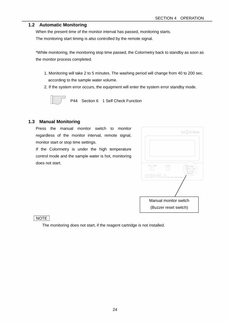
1.3 Manual Monitoring
Press the manual monitor switch to monitor
regardless of the monitor interval, remote signal,
monitor start or stop time settings.
If the Colormetry is under the high temperature
control mode and the sample water is hot, monitoring
does not start.
NOTE
The monitoring does not start, if the reagent cartridge is not installed.
Manual monitor switch
(Buzzer reset switch)
SECTION 4 OPERATION
25
2 FUNCTIONS
2.1 Remote Signal Input
2.1.1 Method
Monitoring the stagnant water in the piping may result in an evaluation error or a system
error of the equipment due to the lack of flow. To avoid such errors, the Colormetry provides
the following two methods, which may be used simultaneously.
Method No.1: Monitor start and stop times
The monitor start time [S Start] and monitor stop time [S Stop] settings limit the period
during which monitoring is performed. The provision helps avoid monitoring while water is
not used.
Example: Operation period: 8:00 through 17:00
↓
Set the monitor start time [S Start] at 8:00 and stop time [S Stop] at 17:00
Method No.2: Remote signal input
Connecting the external contact with no-voltage enables to control the Colormetry for
monitoring only while the water softener is turned on, or to suspend monitoring while the
water softener is regeneration.
The purpose of remote signal is to prevent a monitoring while the system, which the
Colormetry is monitoring for, is stopped, such case as the water softener is at the
regenerating period.
2.1.2 Detailed descriptions
The remote signal input may be processed to enable monitoring in either two methods.
[1] The OFF state
[2] The ON state
The two methods are selectable in the setting mode [Set Mode]. Both methods achieve the
same objective (of preventing an evaluation error), though they process the signal
differently.
[1] Monitoring is enabled by remote being turned OFF [S Rte Sgl OFF] (the factory setting)
The OFF state of the remote signal input (the external contact is open) permits
scheduled monitoring after the monitor interval [S Intvl] as preset in the setting mode
[Set Mode].
The monitor interval [S Intvl] may be set in 30 minutes increments up to 240 minutes.
The reagent will last approximately 4 months on the basis of every 60 minutes
monitoring.)
SECTION 4 OPERATION
26
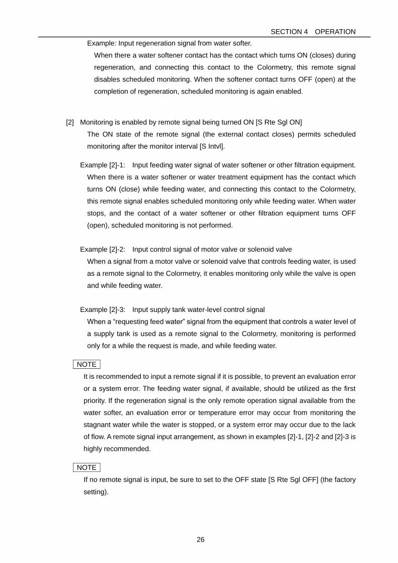
Example: Input regeneration signal from water softer.
When there a water softener contact has the contact which turns ON (closes) during
regeneration, and connecting this contact to the Colormetry, this remote signal
disables scheduled monitoring. When the softener contact turns OFF (open) at the
completion of regeneration, scheduled monitoring is again enabled.
[2] Monitoring is enabled by remote signal being turned ON [S Rte Sgl ON]
The ON state of the remote signal (the external contact closes) permits scheduled
monitoring after the monitor interval [S Intvl].
Example [2]-1: Input feeding water signal of water softener or other filtration equipment.
When there is a water softener or water treatment equipment has the contact which
turns ON (close) while feeding water, and connecting this contact to the Colormetry,
this remote signal enables scheduled monitoring only while feeding water. When water
stops, and the contact of a water softener or other filtration equipment turns OFF
(open), scheduled monitoring is not performed.
Example [2]-2: Input control signal of motor valve or solenoid valve
When a signal from a motor valve or solenoid valve that controls feeding water, is used
as a remote signal to the Colormetry, it enables monitoring only while the valve is open
and while feeding water.
Example [2]-3: Input supply tank water-level control signal
When a “requesting feed water” signal from the equipment that controls a water level of
a supply tank is used as a remote signal to the Colormetry, monitoring is performed
only for a while the request is made, and while feeding water.
NOTE
It is recommended to input a remote signal if it is possible, to prevent an evaluation error
or a system error. The feeding water signal, if available, should be utilized as the first
priority. If the regeneration signal is the only remote operation signal available from the
water softer, an evaluation error or temperature error may occur from monitoring the
stagnant water while the water is stopped, or a system error may occur due to the lack
of flow. A remote signal input arrangement, as shown in examples [2]-1, [2]-2 and [2]-3 is
highly recommended.
NOTE
If no remote signal is input, be sure to set to the OFF state [S Rte Sgl OFF] (the factory
setting).
SECTION 4 OPERATION
27
2.1.3 Delay time of remote signals
The purpose of remote signal delay time [S DelayTime]:
The setting determines the number of seconds the monitoring (filling with the sample
water) is to be delayed after receiving the remote signal. It is not commonly used
function, however it is effective to prevent an evaluation error in the example case
shown below.
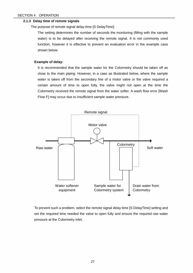
Example of delay:
It is recommended that the sample water for the Colormetry should be taken off as
close to the main piping. However, in a case as illustrated below, where the sample
water is taken off from the secondary line of a motor valve or the valve required a
certain amount of time to open fully, the valve might not open at the time the
Colormetry received the remote signal from the water softer. A wash flow error [Wash
Flow F] may occur due to insufficient sample water pressure.
Raw water
Motor valve
Sample water for
Colormetry system
Remote signal
Water softener
equipment
Drain water from
Colormetry
Soft water
Colormetry
To prevent such a problem, select the remote signal delay time [S DelayTime] setting and
set the required time needed the valve to open fully and ensure the required raw water
pressure at the Colormetry inlet.
SECTION 4 OPERATION
28
2.2 Colormetry Monitor Timing
2.2.1 Automatic monitoring
The interval between monitoring is set in the monitor interval [S Intvl] setting at the setting
mode [Set Mode] (The interval is selectable in 30minutes increments between the 30 to 240
minutes range).
The initial time point of monitor interval [S Intvl] is the first monitoring which carried out soon
after the Colormetry is supplied the power or is reset. The next monitoring will start after the
preset time of the monitor interval [S Intvl] from this initial time point.
If the monitor interval [S Intvl] setting is changed, the initial time point is also changed to the
monitoring soon before the change is made. And the monitoring will start after the new
setting time from the last monitoring.
[1] Without remote signal input
Monitoring is performed periodically at the monitor interval [S Intvl].
[2] With remote signal input
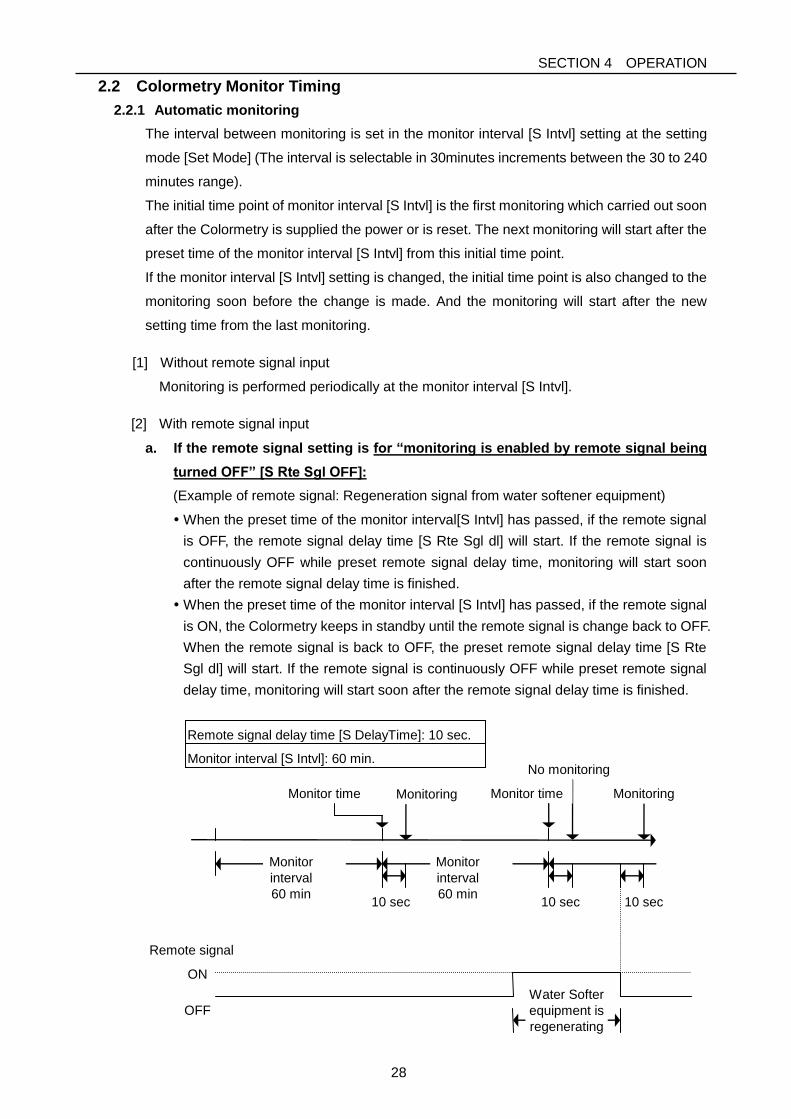
a. If the remote signal setting is for “monitoring is enabled by remote signal being
turned OFF” [S Rte Sgl OFF]:
(Example of remote signal: Regeneration signal from water softener equipment)
When the preset time of the monitor interval[S Intvl] has passed, if the remote signal
is OFF, the remote signal delay time [S Rte Sgl dl] will start. If the remote signal is
continuously OFF while preset remote signal delay time, monitoring will start soon
after the remote signal delay time is finished.
When the preset time of the monitor interval [S Intvl] has passed, if the remote signal
is ON, the Colormetry keeps in standby until the remote signal is change back to OFF.
When the remote signal is back to OFF, the preset remote signal delay time [S Rte
Sgl dl] will start. If the remote signal is continuously OFF while preset remote signal
delay time, monitoring will start soon after the remote signal delay time is finished.
Remote signal delay time [S DelayTime]: 10 sec.
ON
OFF
Remote signal
Monitoring
10 sec 10 sec
No monitoring Monitor interval [S Intvl]: 60 min.
Monitor
interval
60 min
Monitor
interval
60 min
Monitoring
10 sec
Monitor time Monitor time
Water Softer
equipment is
regenerating
SECTION 4 OPERATION
29
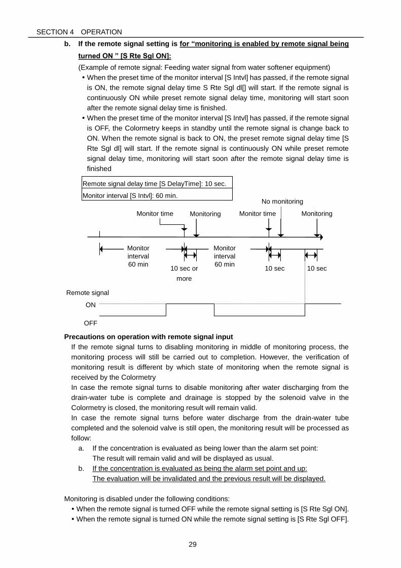
b. If the remote signal setting is for “monitoring is enabled by remote signal being
turned ON ” [S Rte Sgl ON]:
(Example of remote signal: Feeding water signal from water softener equipment)
When the preset time of the monitor interval [S Intvl] has passed, if the remote signal
is ON, the remote signal delay time S Rte Sgl dl[] will start. If the remote signal is
continuously ON while preset remote signal delay time, monitoring will start soon
after the remote signal delay time is finished.
When the preset time of the monitor interval [S Intvl] has passed, if the remote signal
is OFF, the Colormetry keeps in standby until the remote signal is change back to
ON. When the remote signal is back to ON, the preset remote signal delay time [S
Rte Sgl dl] will start. If the remote signal is continuously ON while preset remote
signal delay time, monitoring will start soon after the remote signal delay time is
finished
Remote signal delay time [S DelayTime]: 10 sec.
ON
OFF
Remote signal
Monitoring
10 sec or
more
10 sec
No monitoring Monitor interval [S Intvl]: 60 min.
Monitor
interval
60 min
Monitor
interval
60 min
Monitoring
10 sec
Monitor time Monitor time
Precautions on operation with remote signal input
If the remote signal turns to disabling monitoring in middle of monitoring process, the
monitoring process will still be carried out to completion. However, the verification of
monitoring result is different by which state of monitoring when the remote signal is
received by the Colormetry
In case the remote signal turns to disable monitoring after water discharging from the
drain-water tube is complete and drainage is stopped by the solenoid valve in the
Colormetry is closed, the monitoring result will remain valid.
In case the remote signal turns before water discharge from the drain-water tube
completed and the solenoid valve is still open, the monitoring result will be processed as
follow:
a. If the concentration is evaluated as being lower than the alarm set point:
The result will remain valid and will be displayed as usual.
b. If the concentration is evaluated as being the alarm set point and up:
The evaluation will be invalidated and the previous result will be displayed.
Monitoring is disabled under the following conditions:
When the remote signal is turned OFF while the remote signal setting is [S Rte Sgl ON].
When the remote signal is turned ON while the remote signal setting is [S Rte Sgl OFF].
SECTION 4 OPERATION
30
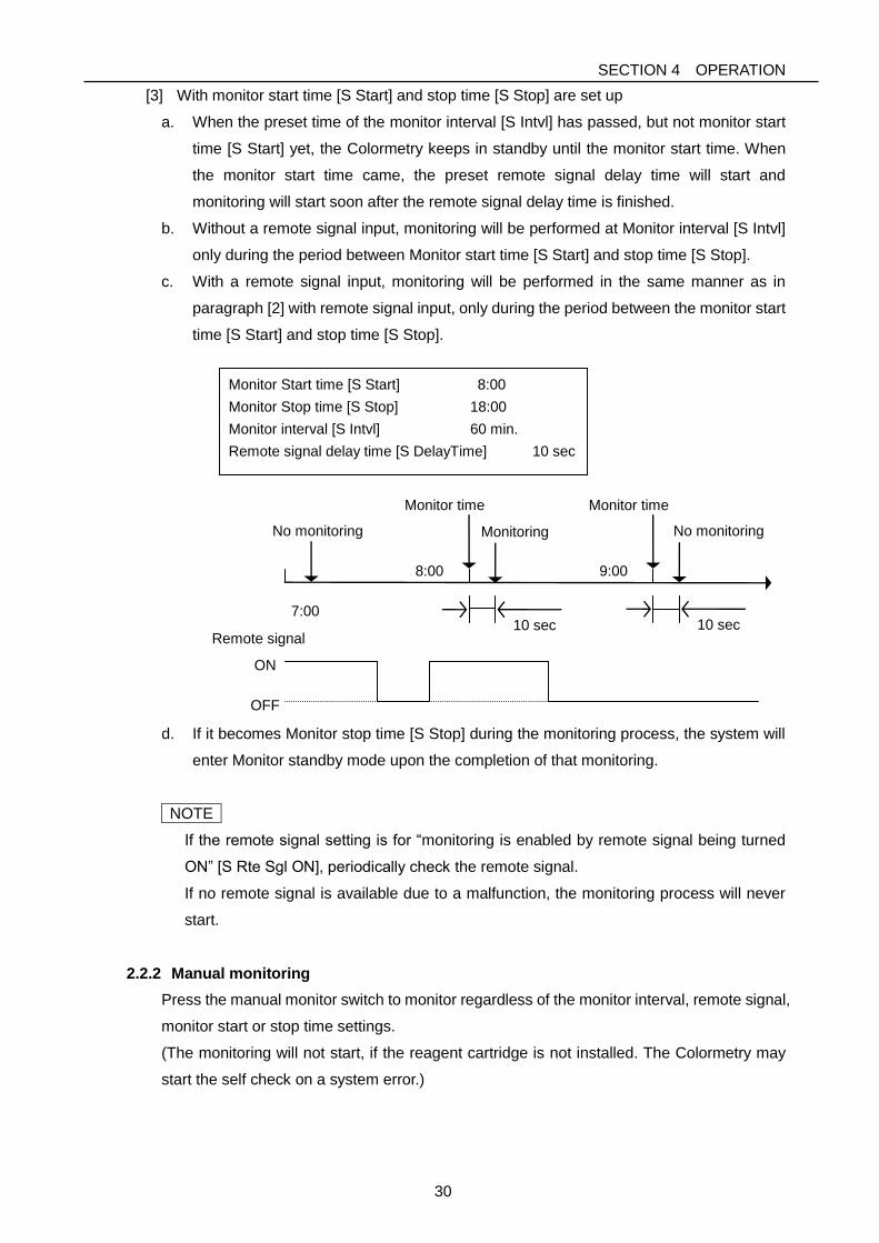
[3] With monitor start time [S Start] and stop time [S Stop] are set up
a. When the preset time of the monitor interval [S Intvl] has passed, but not monitor start
time [S Start] yet, the Colormetry keeps in standby until the monitor start time. When
the monitor start time came, the preset remote signal delay time will start and
monitoring will start soon after the remote signal delay time is finished.
b. Without a remote signal input, monitoring will be performed at Monitor interval [S Intvl]
only during the period between Monitor start time [S Start] and stop time [S Stop].
c. With a remote signal input, monitoring will be performed in the same manner as in
paragraph [2] with remote signal input, only during the period between the monitor start
time [S Start] and stop time [S Stop].
Monitor Start time [S Start] 8:00
Monitor Stop time [S Stop] 18:00
Monitor interval [S Intvl] 60 min.
Remote signal delay time [S DelayTime] 10 sec
ON
OFF
Remote signal
Monitoring
10 sec 10 sec
No monitoring
7:00
No monitoring
8:00 9:00
Monitor time Monitor time
d. If it becomes Monitor stop time [S Stop] during the monitoring process, the system will
enter Monitor standby mode upon the completion of that monitoring.
NOTE
If the remote signal setting is for “monitoring is enabled by remote signal being turned
ON” [S Rte Sgl ON], periodically check the remote signal.
If no remote signal is available due to a malfunction, the monitoring process will never
start.
2.2.2 Manual monitoring
Press the manual monitor switch to monitor regardless of the monitor interval, remote signal,
monitor start or stop time settings.
(The monitoring will not start, if the reagent cartridge is not installed. The Colormetry may
start the self check on a system error.)
SECTION 4 OPERATION
31
2.3 Concentration Evaluation
The Colormetry evaluates ionic concentrations in 5 levels: 0mg/L, 1mg/L, 2mg/L, 3mg/L, and
5mg/l.
Alarm set point may be set to trigger at 1mg/L and up, 2mg/L and up, 3mg/L and up and 5mg/L
and up.
NOTE
For boiler use, select 1mg/L or 2mg/L as the alarm set point or follow the equipment in the
boiler.
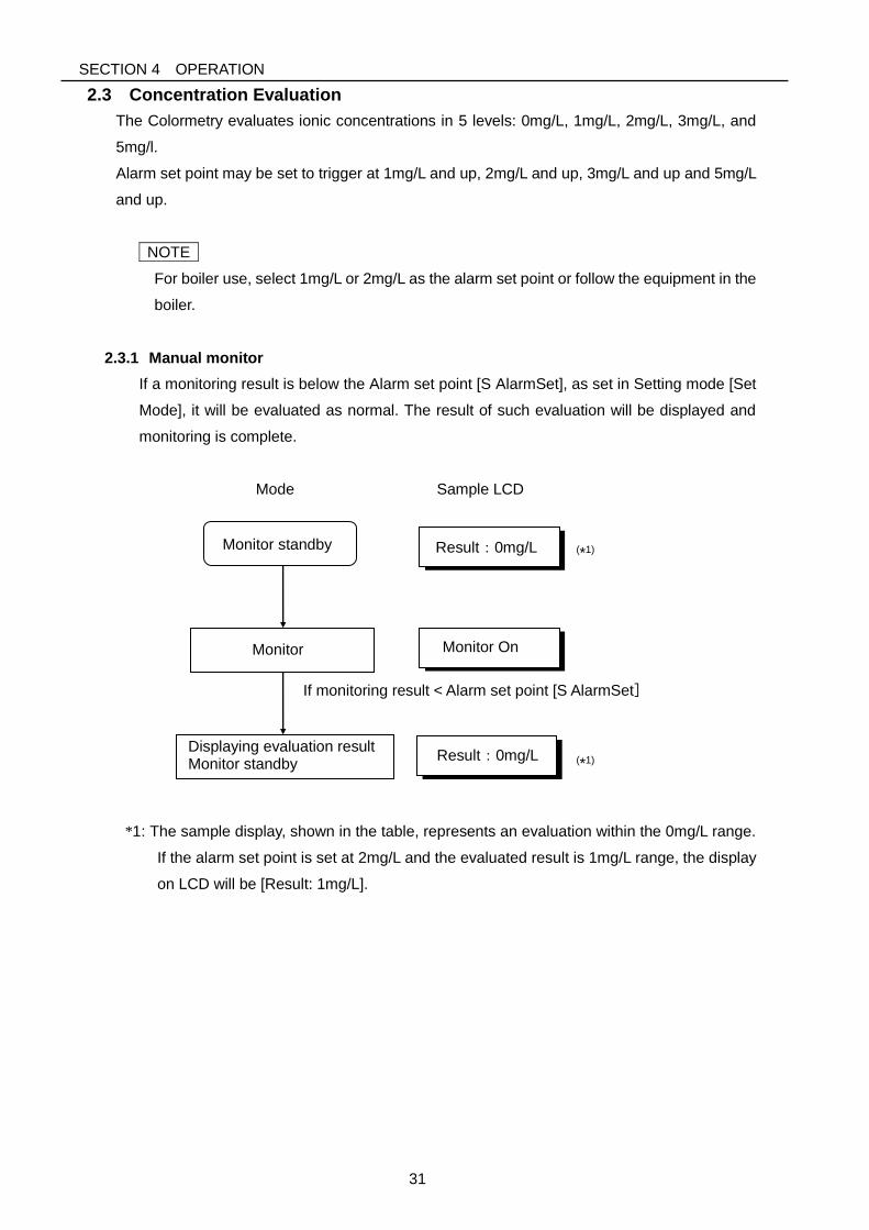
2.3.1 Manual monitor
If a monitoring result is below the Alarm set point [S AlarmSet], as set in Setting mode [Set
Mode], it will be evaluated as normal. The result of such evaluation will be displayed and
monitoring is complete.
Mode Sample LCD
*1: The sample display, shown in the table, represents an evaluation within the 0mg/L range.
If the alarm set point is set at 2mg/L and the evaluated result is 1mg/L range, the display
on LCD will be [Result: 1mg/L].
(*1)
(*1)
Monitor
Monitor standby
Displaying evaluation result Monitor standby
Monitor On
Result:0mg/L
If monitoring result < Alarm set point [S AlarmSet]
Result:0mg/L
SECTION 4 OPERATION
32
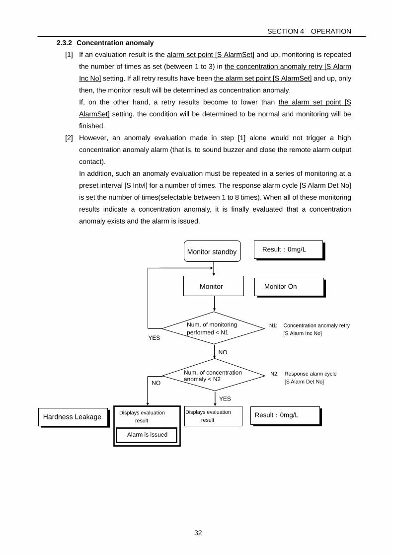
2.3.2 Concentration anomaly
[1] If an evaluation result is the alarm set point [S AlarmSet] and up, monitoring is repeated
the number of times as set (between 1 to 3) in the concentration anomaly retry [S Alarm
Inc No] setting. If all retry results have been the alarm set point [S AlarmSet] and up, only
then, the monitor result will be determined as concentration anomaly.
If, on the other hand, a retry results become to lower than the alarm set point [S
AlarmSet] setting, the condition will be determined to be normal and monitoring will be
finished.
[2] However, an anomaly evaluation made in step [1] alone would not trigger a high
concentration anomaly alarm (that is, to sound buzzer and close the remote alarm output
contact).
In addition, such an anomaly evaluation must be repeated in a series of monitoring at a
preset interval [S Intvl] for a number of times. The response alarm cycle [S Alarm Det No]
is set the number of times(selectable between 1 to 8 times). When all of these monitoring
results indicate a concentration anomaly, it is finally evaluated that a concentration
anomaly exists and the alarm is issued.
YES
Result:0mg/L
N1: Concentration anomaly retry
[S Alarm Inc No]
N2: Response alarm cycle
[S Alarm Det No]
Displays evaluation
result
Monitor standby
Monitor
Result:0mg/L
Monitor On
Num. of monitoring
performed < N1
Displays evaluation
result
Hardness Leakage
Alarm is issued
YES
NO
NO
Num. of concentration anomaly < N2
SECTION 4 OPERATION
33
[3] If a concentration anomaly occurs repeatedly in a series of automatic monitoring at the
monitor interval [S Intvl], or in manual monitoring, the concentration anomaly alarm will
stay on continuously.
[4] The concentration anomaly alarm is automatically terminated (the buzzer stops and the
remote alarm output contact opens) upon that the condition is determined normal in
automatic monitoring at the monitor interval [S Intvl], or in manual monitoring.
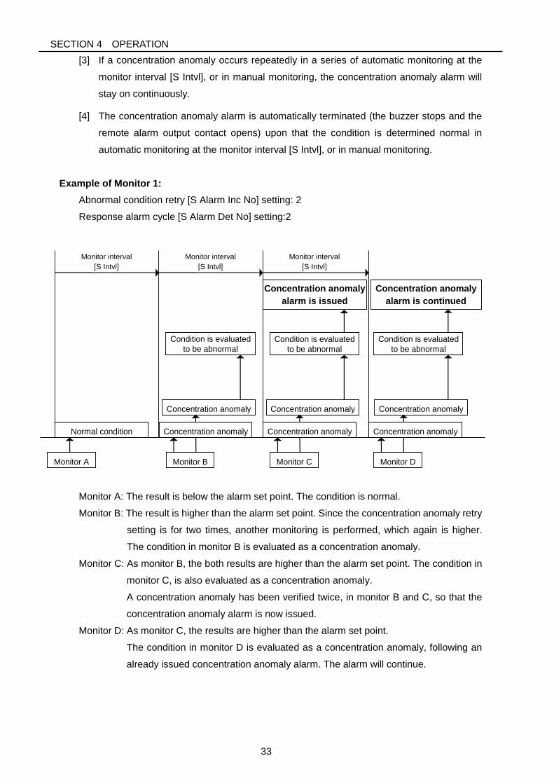
Example of Monitor 1:
Abnormal condition retry [S Alarm Inc No] setting: 2
Response alarm cycle [S Alarm Det No] setting:2
Monitor interval
[S Intvl]
Monitor interval
[S Intvl]
Monitor A Monitor B
Monitor interval
[S Intvl]
Monitor C
Monitor D
Concentration anomaly
alarm is issued
Condition is evaluated
to be abnormal
Normal condition Concentration anomaly
Concentration anomaly Concentration anomaly Concentration anomaly
Concentration anomaly Concentration anomaly
Condition is evaluated
to be abnormal
Condition is evaluated
to be abnormal
Concentration anomaly
alarm is continued
Monitor A: The result is below the alarm set point. The condition is normal.
Monitor B: The result is higher than the alarm set point. Since the concentration anomaly retry
setting is for two times, another monitoring is performed, which again is higher.
The condition in monitor B is evaluated as a concentration anomaly.
Monitor C: As monitor B, the both results are higher than the alarm set point. The condition in
monitor C, is also evaluated as a concentration anomaly.
A concentration anomaly has been verified twice, in monitor B and C, so that the
concentration anomaly alarm is now issued.
Monitor D: As monitor C, the results are higher than the alarm set point.
The condition in monitor D is evaluated as a concentration anomaly, following an
already issued concentration anomaly alarm. The alarm will continue.
SECTION 4 OPERATION
34
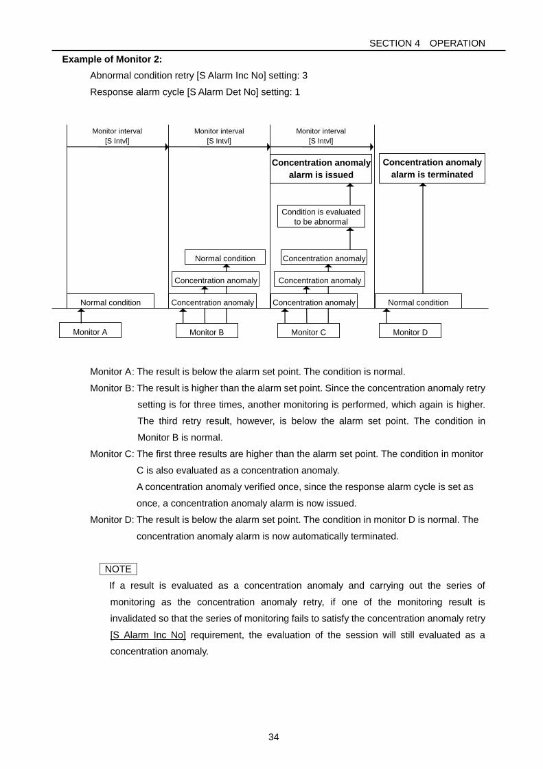
Example of Monitor 2:
Abnormal condition retry [S Alarm Inc No] setting: 3
Response alarm cycle [S Alarm Det No] setting: 1
Monitor interval
[S Intvl]
Monitor interval
[S Intvl]
Monitor A Monitor B
Monitor interval
[S Intvl]
Monitor C
Monitor D
Concentration anomaly
alarm is issued
Normal condition Concentration anomaly
Concentration anomaly Concentration anomaly
Concentration anomaly Normal condition
Condition is evaluated
to be abnormal
Concentration anomaly
alarm is terminated
Normal condition Concentration anomaly
Monitor A: The result is below the alarm set point. The condition is normal.
Monitor B: The result is higher than the alarm set point. Since the concentration anomaly retry
setting is for three times, another monitoring is performed, which again is higher.
The third retry result, however, is below the alarm set point. The condition in
Monitor B is normal.
Monitor C: The first three results are higher than the alarm set point. The condition in monitor
C is also evaluated as a concentration anomaly.
A concentration anomaly verified once, since the response alarm cycle is set as
once, a concentration anomaly alarm is now issued.
Monitor D: The result is below the alarm set point. The condition in monitor D is normal. The
concentration anomaly alarm is now automatically terminated.
NOTE
If a result is evaluated as a concentration anomaly and carrying out the series of
monitoring as the concentration anomaly retry, if one of the monitoring result is
invalidated so that the series of monitoring fails to satisfy the concentration anomaly retry
[S Alarm Inc No] requirement, the evaluation of the session will still evaluated as a
concentration anomaly.
SECTION 4 OPERATION
35
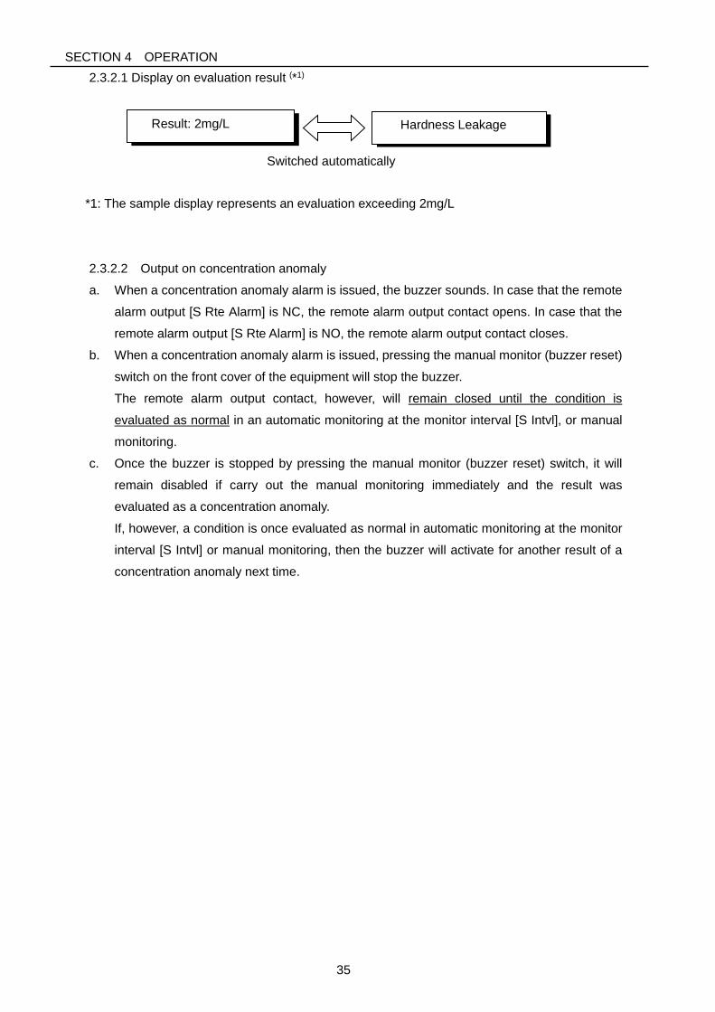
2.3.2.1 Display on evaluation result (*1)
Switched automatically
*1: The sample display represents an evaluation exceeding 2mg/L
2.3.2.2 Output on concentration anomaly
a. When a concentration anomaly alarm is issued, the buzzer sounds. In case that the remote
alarm output [S Rte Alarm] is NC, the remote alarm output contact opens. In case that the
remote alarm output [S Rte Alarm] is NO, the remote alarm output contact closes.
b. When a concentration anomaly alarm is issued, pressing the manual monitor (buzzer reset)
switch on the front cover of the equipment will stop the buzzer.
The remote alarm output contact, however, will remain closed until the condition is
evaluated as normal in an automatic monitoring at the monitor interval [S Intvl], or manual
monitoring.
c. Once the buzzer is stopped by pressing the manual monitor (buzzer reset) switch, it will
remain disabled if carry out the manual monitoring immediately and the result was
evaluated as a concentration anomaly.
If, however, a condition is once evaluated as normal in automatic monitoring at the monitor
interval [S Intvl] or manual monitoring, then the buzzer will activate for another result of a
concentration anomaly next time.
Result: 2mg/L
Hardness Leakage
SECTION 4 OPERATION
36
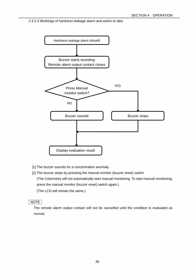
2.3.2.3 Workings of hardness leakage alarm and action to take
Hardness leakage alarm issued
Buzzer starts sounding
Remote alarm output contact closes
Press Manual
monitor switch?
Buzzer sounds
Display evaluation result
NO
Buzzer stops
YES
[1] The buzzer sounds for a concentration anomaly.
[2] The buzzer stops by pressing the manual monitor (buzzer reset) switch.
(The Colormetry will not automatically start manual monitoring. To start manual monitoring,
press the manual monitor (buzzer reset) switch again.)
(The LCD will remain the same.)
NOTE
The remote alarm output contact will not be cancelled until the condition is evaluated as
normal.
SECTION 5 INSPECTION AND MAINTENANCE
37
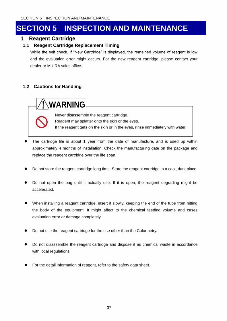
Never disassemble the reagent cartridge.
Reagent may splatter onto the skin or the eyes.
If the reagent gets on the skin or in the eyes, rinse immediately with water.
SECTION 5 INSPECTION AND MAINTENANCE
1 Reagent Cartridge
1.1 Reagent Cartridge Replacement Timing
While the self check, if “New Cartridge” is displayed, the remained volume of reagent is low
and the evaluation error might occurs. For the new reagent cartridge, please contact your
dealer or MIURA sales office.
1.2 Cautions for Handling
The cartridge life is about 1 year from the date of manufacture, and is used up within
approximately 4 months of installation. Check the manufacturing date on the package and
replace the reagent cartridge over the life span.
Do not store the reagent cartridge long time. Store the reagent cartridge in a cool, dark place.
Do not open the bag until it actually use. If it is open, the reagent degrading might be
accelerated.
When installing a reagent cartridge, insert it slowly, keeping the end of the tube from hitting
the body of the equipment. It might affect to the chemical feeding volume and cases
evaluation error or damage completely.
Do not use the reagent cartridge for the use other than the Colormetry.
Do not disassemble the reagent cartridge and dispose it as chemical waste in accordance
with local regulations.
For the detail information of reagent, refer to the safety data sheet.
WARNING
SECTION 5 INSPECTION AND MAINTENANCE
38
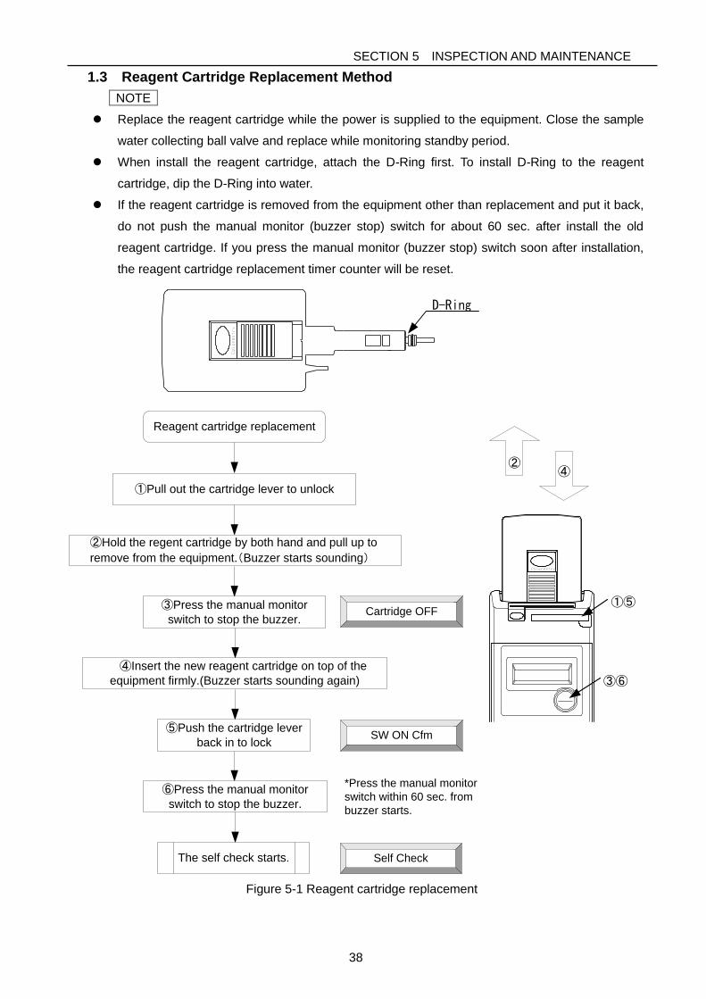
1.3 Reagent Cartridge Replacement Method
NOTE
Replace the reagent cartridge while the power is supplied to the equipment. Close the sample
water collecting ball valve and replace while monitoring standby period.
When install the reagent cartridge, attach the D-Ring first. To install D-Ring to the reagent
cartridge, dip the D-Ring into water.
If the reagent cartridge is removed from the equipment other than replacement and put it back,
do not push the manual monitor (buzzer stop) switch for about 60 sec. after install the old
reagent cartridge. If you press the manual monitor (buzzer stop) switch soon after installation,
the reagent cartridge replacement timer counter will be reset.
Reagent cartridge replacement
Cartridge OFF
①Pull out the cartridge lever to unlock
②Hold the regent cartridge by both hand and pull up to
remove from the equipment.(Buzzer starts sounding)
③Press the manual monitor
switch to stop the buzzer.
④Insert the new reagent cartridge on top of the
equipment firmly.(Buzzer starts sounding again)
⑤Push the cartridge lever
back in to lockSW ON Cfm
⑥Press the manual monitor
switch to stop the buzzer.
The self check starts. Self Check
*Press the manual monitor
switch within 60 sec. from
buzzer starts.
Figure 5-1 Reagent cartridge replacement
①⑤
③⑥
②④
D-Ring
SECTION 5 INSPECTION AND MAINTENANCE
39
Do not place anything which might cause electric leakage underneath the
equipment.
The equipment is designed to drain water from the bottom of the equipment if
there is inner water leakage. Water might splash to the item under the
equipment.
2 Fiber Filter and Constant Flow Valve Replacement
2.1 Fiber Filter Replacement Timing
If “Wash F : F265”, “Injection F : F281” and “Wash Flow: F0866” displayed even though the
raw water pressure is the normal range and there are no other cause, the fiber filter might
clogged.
The filter life is about an year, but it might be shorten depend on the water quality.
If there are no alarm displayed, replace the fiber filter every year.
2.2 Fiber Filter Replacement
2.2.1 Remove filter casing assembly
1) Close the sample water collecting ball valve.
2) Press the manual monitor (buzzer stop) switch to carry out manual monitoring to reduce the
internal pressure.
3) 15 sec. after pressing the manual monitor (buzzer stop) switch; cut the power supply off from
the equipment.
NOTE
When you take off the feed-water tube, push the release bush on the tube joint and pull the tube
out (refer to Fig. 5-3). If you pull the tube without pushing the bush, end of the tube clogged in the
tube joint and small pieces of the tube might be remained. When you push the new tube in, it
might not able to push it through.
4) Pull off the feed-water tube from the filter casing assembly.
5) Take out the filter casing assembly from the Colormetry.
6) When you take out the filter casing assembly, the constant flow valve is on top of the filter
casing assembly. If it is not there, it might remain in the Colormetry. If so take it out gently.
CAUTION
SECTION 5 INSPECTION AND MAINTENANCE
40
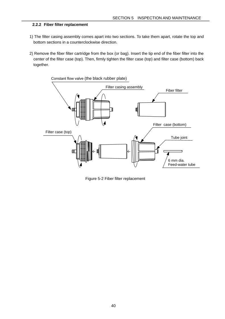
2.2.2 Fiber filter replacement
1) The filter casing assembly comes apart into two sections. To take them apart, rotate the top and
bottom sections in a counterclockwise direction.
2) Remove the fiber filter cartridge from the box (or bag). Insert the tip end of the fiber filter into the
center of the filter case (top). Then, firmly tighten the filter case (top) and filter case (bottom) back
together.
Filter casing assembly
Constant flow valve (the black rubber plate)
Fiber filter
Tube joint
Filter case (bottom)
Filter case (top)
6 mm dia.Feed-water tube
Figure 5-2 Fiber filter replacement

SECTION 5 INSPECTION AND MAINTENANCE
41
Do not apply grease or lube when install the filter casing assembly. It might
damage the material of the equipment and cause water leakage.
2.2.3 Filter case assembly installation
NOTE
When you install the filter casing assembly, simply screw it in by hand. Do not use any kind of
fitting tool. If you use tools to screw in with excess power, the filter casing assembly and the
bottom plate of the Colormetry might be broken.
1) Attach the constant flow valve on top of the filter casing assembly, then screw in the filter
casing assembly into the Colormetry.
NOTE
If using the removed tube once again, cut the end of the tube clean and even by the tube
cutter. Exercise with care to avoid injury when using the tube cutter.
2) Push in the feed-water tube to the filter case assembly
3) Open the sample water collecting ball valve and make sure there is no leakage.
4) Supply the power to the Colormetry.
Screw the filter casing assembly into
the bottom of the equipment and insert
the 6mm dia. feed-water tube into the
joint firmly.
※If the filter casing assembly is
screwed with the tube, the tube or the
tube joint may turn around and
damage itself, then the connection
becomes loose.
Before screwing in the filter
casing assembly, be sure that
the constant flow valve is fitted.
Bundle the tube together with a
cable tie.
Be sure that no undue force is
exerted on the tube.
※If the tube is tighten too hard
until it changes its shape,
it can crack and cause water
leakage.
Attach the warning label "Don't apply
grease or lube" to the filter casing
assembly, after that, place it to be
seen from the front.
Insert the 8mm dia.Drain-water tube properly into the Cylindrical part.
Figure 5-3 Filter case assembly installation
CAUTION
SECTION 5 INSPECTION AND MAINTENANCE
42
Do not use the equipment if there is smoke, abnormal odor or noise,
excessive overheating, or other abnormalities. If an abnormality occurs, do
not operate the equipment. Also, make sure an earth leakage circuit breaker
is turned OFF and a main feed-water valve is closed and contact your dealer
or MIURA sales office.
Failure to observe this precaution may lead to electric shock, fire, or a fault.
Replace a tube if a defect such as deformation (a bend or fold), discoloration,
hardening, or cracking is detected on the tube surface. If a deteriorated tube is
continuously used, it can rip and cause water leakage.
Please use specified tubes when exchanging tubes. Using tubes other than
specified tubes may cause leakage.
3 Daily Inspection
3.1 Inspection Item
NOTE
Please wipe with dry soft cloth when cleaning.
Rubbing with hard cloth may make scratches.
3.1.1 Monitor operation
Make sure it is monitoring automatically. If the remote signal input is used, but the remote
signal has some problem, the automatic monitoring does not start.
P24 Section 4 1.2 Automatic Monitoring
3.1.2 Feed-water and drain-water tube
Exercise with care to keeping the tubes free from bents or holds.
If the feed-water tube is bent, it might cause insufficient feed water volume.
If the drain-water tube is clogged, the internal pressure builds up in the equipment and
causes water leakage. Use specified tubes when exchanging tubes. Using tubes other than
specified tubes may cause leakage.
CAUTION
WARNING
SECTION 5 INSPECTION AND MAINTENANCE
43
If there is a defect or cracking on the filter casing assembly, turn OFF an earth
leakage circuit breaker and close a main feed-water valve. Then, replace the
filter casing assembly.
If water leakage is not stopped even though tightening the filter casing
assembly and tube joint, replace the filter casing assembly.
3.1.3 Filter case assembly
3.2 Others
・When the hardness leakage occurred (CMU-324HE)
The hardness leaking is very low concentration such as 1.0 mg/L or 2.0 mg/L, it cannot
determined by the hardness indicator. To determine, carry out the water quality analysis.
Collect the sample water from raw water into the Colormetry or utilize drain water which does
not colored by reagent used in the Colormetry.
CAUTION
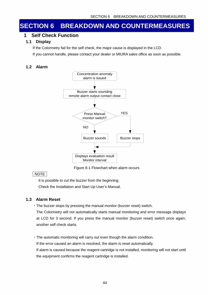
SECTION 6 BREAKDOWN AND COUNTERMEASURES
44
SECTION 6 BREAKDOWN AND COUNTERMEASURES
1 Self Check Function
1.1 Display
If the Colormetry fail for the self check, the major cause is displayed in the LCD.
If you cannot handle, please contact your dealer or MIURA sales office as soon as possible.
1.2 Alarm
Concentration anomaly
alarm is issued
Buzzer starts sounding
remote alarm output contact close
Press Manual
monitor switch?
Buzzer sounds Buzzer stops
Displays evaluation result
Monitor interval
YES
NO
Figure 6-1 Flowchart when alarm occurs
NOTE
It is possible to cut the buzzer from the beginning.
Check the Installation and Start Up User’s Manual.
1.3 Alarm Reset
・The buzzer stops by pressing the manual monitor (buzzer reset) switch.
The Colormetry will not automatically starts manual monitoring and error message displays
at LCD for 3 second. If you press the manual monitor (buzzer reset) switch once again,
another self check starts.
・The automatic monitoring will carry out even though the alarm condition.
If the error caused an alarm is resolved, the alarm is reset automatically.
If alarm is caused because the reagent cartridge is not installed, monitoring will not start until
the equipment confirms the reagent cartridge is installed.
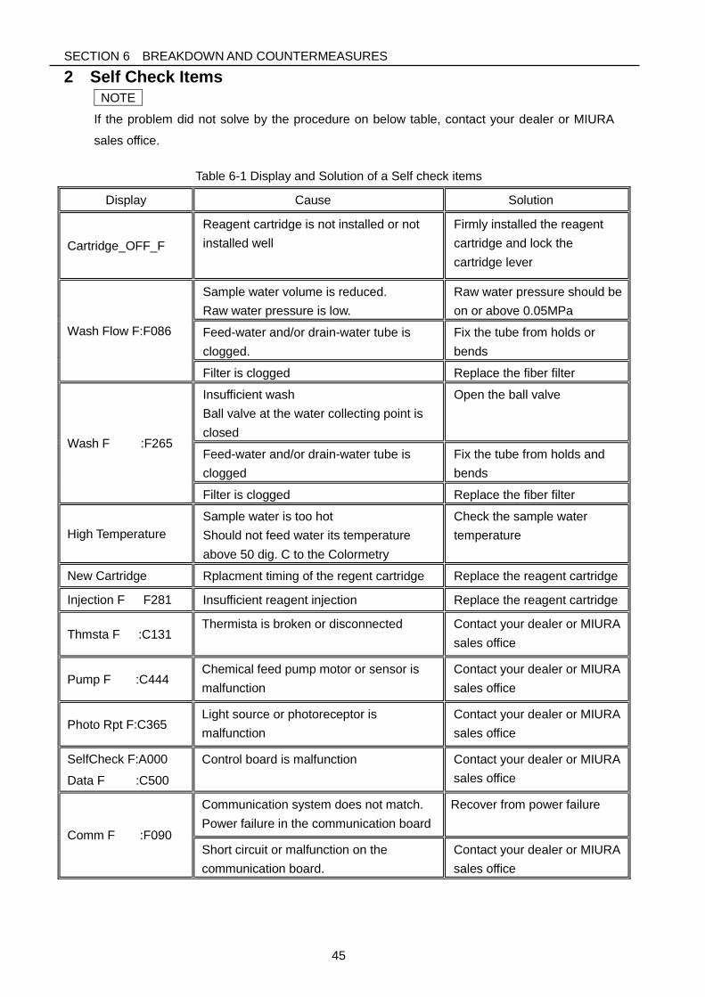
SECTION 6 BREAKDOWN AND COUNTERMEASURES
45
2 Self Check Items
NOTE
If the problem did not solve by the procedure on below table, contact your dealer or MIURA
sales office.
Table 6-1 Display and Solution of a Self check items
Display Cause Solution
Cartridge_OFF_F
Reagent cartridge is not installed or not
installed well
Firmly installed the reagent
cartridge and lock the
cartridge lever
Wash Flow F:F086
Sample water volume is reduced.
Raw water pressure is low.
Raw water pressure should be
on or above 0.05MPa
Feed-water and/or drain-water tube is
clogged.
Fix the tube from holds or
bends
Filter is clogged Replace the fiber filter
Wash F :F265
Insufficient wash
Ball valve at the water collecting point is
closed
Open the ball valve
Feed-water and/or drain-water tube is
clogged
Fix the tube from holds and
bends
Filter is clogged Replace the fiber filter
High Temperature
Sample water is too hot
Should not feed water its temperature
above 50 dig. C to the Colormetry
Check the sample water
temperature
New Cartridge Rplacment timing of the regent cartridge Replace the reagent cartridge
Injection F F281 Insufficient reagent injection Replace the reagent cartridge
Thmsta F :C131 Thermista is broken or disconnected Contact your dealer or MIURA
sales office
Pump F :C444 Chemical feed pump motor or sensor is
malfunction
Contact your dealer or MIURA
sales office
Photo Rpt F:C365 Light source or photoreceptor is
malfunction
Contact your dealer or MIURA
sales office
SelfCheck F:A000
Data F :C500
Control board is malfunction Contact your dealer or MIURA
sales office
Comm F :F090
Communication system does not match.
Power failure in the communication board
Recover from power failure
Short circuit or malfunction on the
communication board.
Contact your dealer or MIURA
sales office
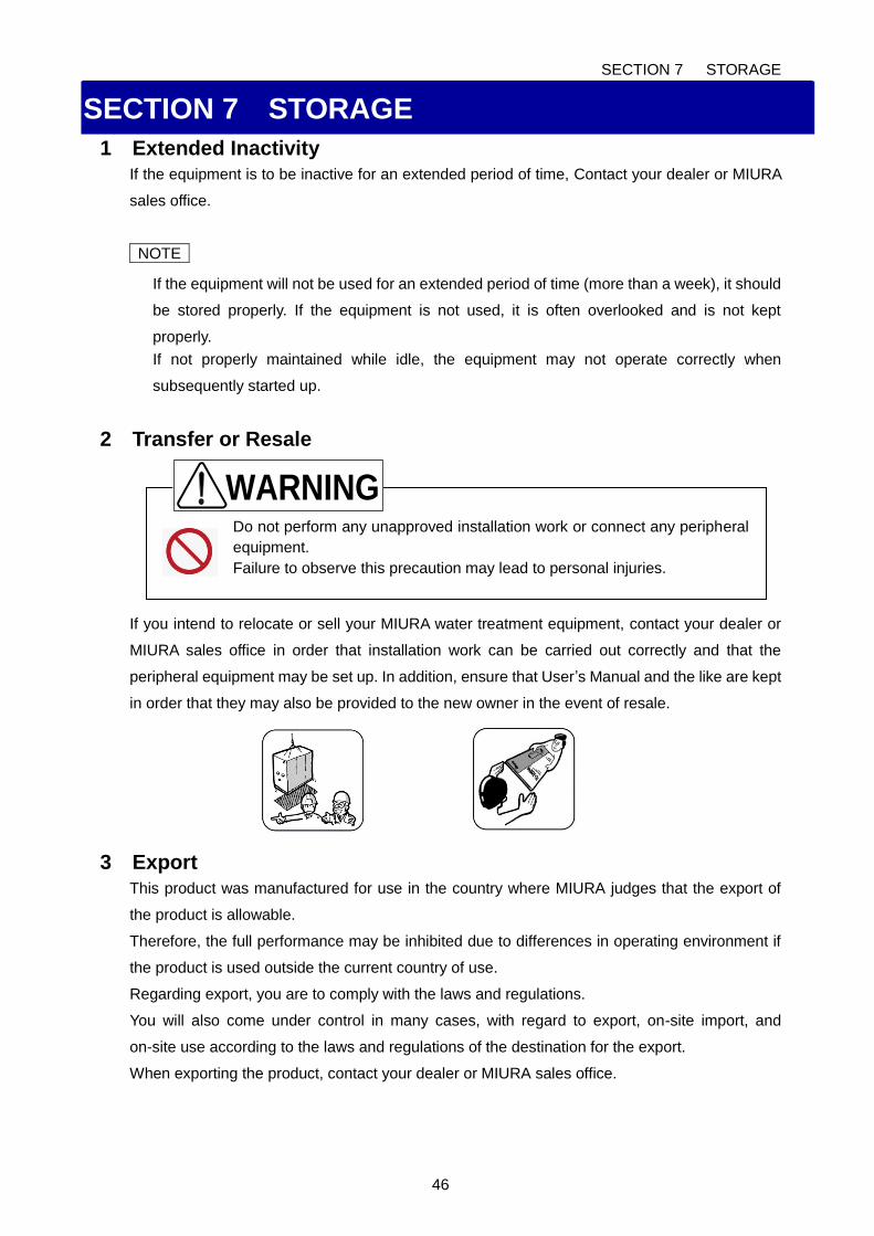
SECTION 7 STORAGE
46
Do not perform any unapproved installation work or connect any peripheral
equipment.
Failure to observe this precaution may lead to personal injuries.
SECTION 7 STORAGE
1 Extended Inactivity
If the equipment is to be inactive for an extended period of time, Contact your dealer or MIURA
sales office.
NOTE
If the equipment will not be used for an extended period of time (more than a week), it should
be stored properly. If the equipment is not used, it is often overlooked and is not kept
properly.
If not properly maintained while idle, the equipment may not operate correctly when
subsequently started up.
2 Transfer or Resale
If you intend to relocate or sell your MIURA water treatment equipment, contact your dealer or
MIURA sales office in order that installation work can be carried out correctly and that the
peripheral equipment may be set up. In addition, ensure that User’s Manual and the like are kept
in order that they may also be provided to the new owner in the event of resale.
3 Export
This product was manufactured for use in the country where MIURA judges that the export of
the product is allowable.
Therefore, the full performance may be inhibited due to differences in operating environment if
the product is used outside the current country of use.
Regarding export, you are to comply with the laws and regulations.
You will also come under control in many cases, with regard to export, on-site import, and
on-site use according to the laws and regulations of the destination for the export.
When exporting the product, contact your dealer or MIURA sales office.
WARNING
SECTION 8 DISPOSAL
47
SECTION 8 DISPOSAL
1 Disposal
When disposing of the product, comply with the laws and regulations.
SECTION 9 WARRANTY
48
SECTION 9 WARRANTY
1 Note Regarding Warranty
Regarding the contents of the warranty, contact your dealer or MIURA sales office.
2 Questions Regarding the Product and User’s Manual
For any questions about your purchased product or the content of this User’s Manual, contact
your dealer or MIURA sales office.
3 If the User’s Manual is Lost
The User’s Manual contains the information for the safe usage.
In the event of loss of the User’s Manual, contact your dealer or MIURA sales office.


AUTHORIZED REPRESENTATIVE in EU
Wolfgang Kiebert
Industrie- und Verfahrenstechnik
Dipl.-Ing. Wolfgang Kiebert
Kapellenstr. 19
D-54597 Auw bei Prüm
Tel.: +49 (0)6552 92 99 000
Fax: +49 (0)6552 92 99 004
Mobil: +49 (0)172 42 22 416
email:[email protected]
GERMANY, Mar 2017