Embed Size (px)
Citation preview
General Installation Guidelines
for
INSULATION
Eighth Edition – January 2009
Contains 100% recycled paper M – an official mark of Environment Canada
MANUFACTURED BY:
CAN-CELL INDUSTRIES INC. Head Office: 14735-124 Avenue, Edmonton, Alberta T5L 3B2
Phone (780) 447-1255 Fax (780) 447-1034
www.can-cell.com
1-800-661-5031

Can-Cell Industries Inc. – Manufactured Products Division Page 2 of 18
General Installation Guidelines for Weathershield™ Insulation Revised January 2009
TABLE OF CONTENTS
Page
TABLE OF CONTENTS 2
PREFACE 3
1. SCOPE & SIGNIFICANCE 4
2. REFERENCES 4
3. DEFINITIONS 4
4. SYMBOLS AND ABBREVIATED TERMS 5
5. GENERAL CHARACTERISTICS OF WEATHERSHIELD™ 5
5.1 Composition and Physical Nature 5 5.2 General Properties 5 5.3 Physical Properties 6 5.4 Storage 6
6. INSPECTION 6
6.1 Building Construction 6 6.2 Vapour Barriers 7 6.3 Ventilation 7 6.4 Limitations and Safety Precautions 8
7. PREPARATION 9
7.1 New Construction 9 7.2 Retrofit Installations 10
8. COVERAGE REQUIREMENTS 11
9. APPLICATION PROCEDURES 12
9.1 Attic & Ceiling Applications 12 9.2 Wall Applications 13
9.3 Sloped Ceilings & Flat Roofs 14 9.4 Windows & Doors 15 9.5 Floors & Rim Joists 15
10. EQUIPMENT 16
10.1 Insulating Machines 16 10.2 Delivery Hose & Nozzles 17 10.3 Maintenance 17
11. JOB SITE PLACARD 18
APPENDICES Appendix A: Weathershield™ Coverage Charts 2 pages
Appendix B: Guidelines for Hand-Pour (Manual) Application 1 page
Appendix C: Application Summary for WallBAR™ Insulation 1 page
Appendix D: Alternatives for Retrofitting Sidewalls and Ceiling Cavities 3 pages
General Installation Guidelines for Weathershield™ Insulation Revised January 2009
GENERAL INSTALLATION GUIDELINES FOR
PREFACE
The Manufactured Products Division of Can-Cell Industries Inc. has prepared this edition of the “General Installation Guidelines for Weathershield™ Insulation”. These guidelines were developed to reflect the common elements and general recommended practices regarding application procedures used across Canada to provide quality installations of cellulose fibre insulation (CFI) products such as Weathershield™. These guidelines can be used by anyone and is not intended to limit the use of Weathershield™ or restrict who may apply Weathershield™ Insulation. It is important to note that it remains the responsibility of the user of these installation guidelines to judge their suitability for the particular application. Not all possible scenarios are represented here. An application of Weathershield™ that appears to follow these guidelines will not necessarily be acceptable if, upon inspection, it is found to employ significantly different coverage values, forms of construction or other features not covered by the Guidelines, which may impair the intended result in quality and/or performance.
Can-Cell Industries Inc. – Manufactured Products Division Page 3 of 18
Can-Cell Industries Inc. – Manufactured Products Division Page 4 of 18
General Installation Guidelines for Weathershield™ Insulation Revised January 2009
1. SCOPE & SIGNIFICANCE
These installation guidelines cover the recommended methods of pneumatically installing loose-fill cellulose fibre insulation (CFI) – Weathershield™ specifically – in attics, flat or sloped roofs, wall cavities, floors, rim joists and in crawl spaces of single and multi-family dwellings, for both new construction and retrofit applications. Manual (hand-pour) application of Weathershield™ in attics is also presented. The guidelines also identify precautions that need to be taken.
These guidelines are intended for the installation of Weathershield™ manufactured in accordance with CAN/ULC-S703 for either thermal applications and/or acoustical applications. Floor installations intended for acoustical control need only be partially filled – a minimum average thickness of 3.5” (89 mm) is recommended unless full thermal or acoustical value is also desired.
All new construction installation must consider the National Building Code (NBC) or other code requirements. Purely retrofit applications allow for proven alternative techniques to be used.
2. REFERENCES
Underwriter’s Laboratories of Canada (ULC) CAN/ULC-S703 – Standard for Cellulose Fibre Insulation (CFI) for Buildings
American Society for Testing and Materials (ASTM) C-168 – Standard Definition of Terms Relating to Thermal Insulating Materials
C-739 – Standard Specification for Cellulosic Fiber (Wood Base) Loose Fill Thermal Insulation
C-1015 – Standard Practice for Installation of Cellulosic and Mineral Fiber Loose-Fill Thermal Insulation
C-1149 – Standard Specification for Self-Supported Spray Applied Cellulosic Thermal/Acoustical Insulation 3. DEFINITIONS
Applied Thickness – the average thickness of insulation provided immediately after installation. For certain applications, it may be 5-12% greater than the settled thickness. The terms “blown” and “installed thickness” are also used.
Backer board – a rigid, non-vapour-barrier-forming material such as gypsum board or plywood which is used to cover the open side of an existing wall forming a cavity which may be filled with insulation. It must have sufficient strength to withstand pressures developed when filling the cavity.
Blocking – any material used to divide the area to be insulated from an area that is to be left free of insulation (such as soffit areas). When using blocking to isolate heat sources in attics, it is important to ensure that its height exceeds the intended thickness of insulation to be applied. Blocking is also used to divide tall wall cavities (i.e. over 10’/3m in height) for added settlement resistance.
Dense-Pack – application to enclosed cavities (walls, floors, ceilings) where CFI is pneumatically injected to pack the cavity full.
Design Density – the mass-per-unit-volume at which the product attains the stated thermal resistance. For attic applications, it represents the final density achieved once settlement has occurred – also known as “coverage density”.
Enclosed ceiling cavities – ceiling area (joists) covered on both top and bottom.
Fill tube – a tube or nozzle that enables a cavity to be filled through an entry hole.
R(RSI)-Value – common/recognized units of thermal resistance (or insulation value). “R” refers to imperial units; “RSI” refers to metric units. To convert from metric RSI-Value to imperial R-Value, multiply by 5.67829.

Can-Cell Industries Inc. – Manufactured Products Division Page 5 of 18
General Installation Guidelines for Weathershield™ Insulation Revised January 2009
Settled Thickness – the average thickness that the manufacturer declares will provide the corresponding thermal resistance listed in the coverage chart on the product package. The terms “declared” or “design thickness” are also used.
Sidewall – an exterior vertical wall (that is heated on the interior side).
Type 1 CFI – (re: CAN/ULC-S703) Loose-fill CFI pneumatically or manually applied to open spaces (with slopes up to 4.5-in-12) and/or injected into enclosed cavities.
Type 2 CFI – (re: CAN/ULC-S703) CFI pneumatically spray-applied with water to any open space (as in “stabilized” attic installations), or into any cavity (regardless of slope) that will be closed later. Some systems involve spray injection into cavities through a permeable retaining membrane or netting. Such product may also contain internal binders to increase the adhesive/cohesive capabilities of the sprayed fibres in order to reduce settlement.
4. SYMBOLS AND ABBREVIATED TERMS
CCMC Canadian Construction Materials Centre
CFI Cellulose Fibre Insulation
CGSB Canadian General Standards Board
CIMA Cellulose Insulation Manufacturers Association
CIMAC Cellulose Insulation Manufacturers Association of Canada
NBC National Building Code of Canada
NRC National Research Council of Canada 5. GENERAL CHARACTERISTICS OF WEATHERSHIELD™ INSULATION 5.1 Composition and Physical Nature:
Weathershield™ is a CFI product manufactured from select paper stocks and modified with chemical additives to provide fire, fungi and corrosion resistance, as well as other desired characteristics.
Weathershield™ is commonly available in two package sizes – in 11.5-kg (25.35 lb.) poly bags, available through retail yards, and in 14.0-kg (30.86 lb.) poly bags, available to contractors only.
5.2 General Properties:
- Weathershield™ provides a relatively high thermal resistance per unit thickness.
- Weathershield™ provides a highly stable thermal value due to its high resistance to air infiltration and convective heat loss.
- Weathershield™ provides superior acoustical control properties. This is particularly apparent
when cavity systems are dense-packed with Weathershield™ (or WallBAR™).
- Weathershield™ is not subject to installation defects (such as leaving gaps and voids around structural irregularities) that allow heat to escape easily. Its short-fibre nature allows for effectively filling all areas.
- Weathershield™’s fire retardant additives also function to provide high resistance to mould
and fungal growth, as well as to deter pests and other vermin.
Can-Cell Industries Inc. – Manufactured Products Division Page 6 of 18
General Installation Guidelines for Weathershield™ Insulation Revised January 2009
5.3 Physical Properties:
Weathershield™ (like other quality CFI products) conforms to the specified requirements of CAN/ULC-S703, Standard for Cellulose Fibre Insulation (CFI) for Buildings, and provides the following field characteristics:
Thermal Resistance: R/inch: 3.69 (pneumatically applied) RSI/mm: 0.0256
Application Densities: Open (attic): 1.55 lb/ft³ (24.83 kg/m³) (pneumatically applied) Closed (cavity): 3.00 lb/ft³ (48.06 kg/m³)
Exhibiting superior fire control properties, CFI products like Weathershield™ can increase the overall fire resistance of walls (up to 55%) and floors (up to 33%).
5.4 Storage:
Can-Cell’s CFI products must be protected from damage and deterioration and properly stored. Ideally, they should be stored indoors or in secured trucks or trailers. However, if stored outdoors, all CFI products should be stored off the ground in a dry area (protected from precipitation).
6. INSPECTION The following should be given special consideration prior to installing insulation: 6.1 Building Construction:
A brief inspection of the building’s construction is required prior to installation to identify problem areas. The installer should:
- Seal any holes or gaps in ceilings or sidewalls that would allow insulation to escape during
application. - Reinforce weak areas of interior walls (that may not be able to withstand injection pressures)
or mark them for special filling (using less pressure). The builder/homeowner should be made aware of all such situations prior to filling such cavities.
- Seal wall cavities that open into lower floors, basements, crawl spaces, or upper floors so
that insulation does not inadvertently flow into these areas.
- Determine any altered wall cavities, such as for built-in features, which may contain isolated cavities (bulkheads), and mark them for special entry holes.
- Ensure interior wall cavities that serve as air ducts in older homes (or for multi-floor heating or
air conditioning systems) are not to be filled unless alternate ducting is installed.
- Examine exterior walls, siding, roofs and attics for evidence of moisture problems and note the results. Insulating alone may not resolve some problems and additional corrective action may be needed. Existing rot, water leakage or condensation problems must be corrected before applying insulation.
- Remove existing batt insulation in sidewalls that are intended for retrofit application. This may
only be practically done during other renovations, from the exterior when re-siding or from the interior when re-covering. See Appendix D for alternative suggestions and procedures.
- Ensure the homeowner has removed any items stored in the attic space prior to the
installation.
Can-Cell Industries Inc. – Manufactured Products Division Page 7 of 18
General Installation Guidelines for Weathershield™ Insulation Revised January 2009
6.2 Vapour Barriers:
New Construction Most building codes require a vapour barrier on the warm side of an insulated area. Regardless whether a vapour barrier is used, properly installed Weathershield™ exhibits high resistance to air and moisture infiltration and condensation.
Vapour barriers are not required for below-grade wall applications if the building location rates less than 5000 heating degree-days. Check with your building official for the heating degree rating for your location.
A ground surface vapour barrier (6-mil CGSB-approved polyethylene film) is recommended in structures that have a crawl space beneath the floor (see also 6.3 Ventilation).
Retrofit Installations Since cavities are already enclosed, it is often not possible or very difficult to apply polyethylene type vapour barrier films. In such cases, a low vapour permeable paint can be applied to the interior surfaces of walls and ceilings (and some floors) to help reduce excessive moisture transfer by diffusion.
A ground surface vapour barrier (6mil CGSB-approved polyethylene film) is recommended in structures that have a crawl space beneath the floor (see also 6.3 Ventilation).
6.3 Ventilation:
Attic Ventilation
- For vented attics with a vapour barrier, 1.0 ft² (0.1 m²) of unobstructed vent area is recommended for every 300 ft² (30 m²) of insulated ceiling area.
- For vented attics without a vapour barrier or where the roof slope is less than 2-in-12 or in
roofs that are constructed with roof joists, 1.0 ft² (0.1 m²) of unobstructed vent area is recommended for every 150 ft² (15 m²) of insulated ceiling area.
- Where individual vents are used in the soffit, the joist space immediately in front of and on
either side of a vent is to be provided with an air chute and partial blocking to permit air flow to the attic and to keep insulation from filling the soffit area. (Air chutes are more convenient and practical to install in retrofit applications compared to insulation stops). Other spaces should be totally blocked – scrap wood is recommended in new construction, a scrap piece of fibreglass batt (stuffed into place with a broomstick) for retrofit.
- Typically, when a continuous strip vent is used in the soffit, an airflow vent and blocking is to
be provided at every third joist space. The other joist spaces should be completely blocked.
Vents are recommended to be installed with not less than 25% of the total required vent area in the eaves (soffit) and not less than 25% of vent area in the roof near the peak.
Flat Roofs and Sloped Ceilings
The NBC states that not less than 2½” (63 mm) of space shall be provided between the top of the insulation and the underside of the roof sheathing. This does not apply to roof joist spaces interconnected on the top surface by 1½” (38 mm) x 1½” (38 mm) purlins provided the area between the purlins remains unobstructed and vented to the outside. In retrofit applications, filling such cavities completely (leaving no air space) with dense-pack Weathershield™ (at a minimum of 2.5 lb./ft³ (40 kg/m³), providing high resistance to air infiltration and convective heat loss) is a common practice that has no known associated moisture problems.
Can-Cell Industries Inc. – Manufactured Products Division Page 8 of 18
General Installation Guidelines for Weathershield™ Insulation Revised January 2009
Enclosed roof assemblies with slopes exceeding 8:12 (60°) are considered walls. Such assemblies should not require ventilation provided the assembly provides enough depth to achieve the minimum thermal resistance value for your area.
Unheated Crawl Spaces
The NBC states that there is to be a minimum of 1.0 ft² (0.1 m²) of unobstructed vent area for every 538 ft² (50 m²) of floor area.
6.4 Limitations & Safety Precautions:
- Exposure to free water can damage Weathershield™’s chemical treatment, thus reducing its effectiveness and lowering thermal resistance.
- Weathershield™ is not recommended for use inside cement block cavities or for filling the
cavities of masonry walls.
- Weathershield™ must not be in direct contact with high-temperature sources or be installed where the service temperature exceeds 90°C. See also the following caution (printed on each bag of Weathershield™):
CAUTION: Maintain building, electrical, gas and oil safety code clearances between the insulation and heat emitting devices, such as fuel burning appliances, chimney pipes, ducts and vents to these appliances (at least 50 mm) as well as recessed light fixtures (at least 75 mm) unless approved for insulation contact.
- Heaters and recessed light fixtures must not be covered by the insulation unless the fixture
has an IC rating (CSA-approved, with 90°C safety cut-off). If not so rated, then applicable building codes must be followed – most require a minimum of 3 inches (76 mm) of air space to be maintained between the fixture and its blocking (or its enclosure).
- Insulation (of any type) must not contact chimneys or flues. A minimum of 3 inches (76 mm)
of air space must be maintained with blocking used to retain the insulation. Refer to the applicable codes or local building officials for specific requirements.
- Cold air returns and combustion air intakes for hot air furnaces must not be blocked –
insulation must not be installed in a manner that would allow it to be drawn into the heating/cooling system. Air ducts should be checked for loose connections and sealed as required to ensure insulation material cannot be drawn in.
- The installer is advised to wear appropriate respiratory and eye protection during application
of any fibrous insulation product. A NIOSH-approved N95 nuisance dust mask (3M 8210 or equivalent) and eye goggles are recommended as minimum protection.
- The installer should wear adequate head protection to guard against protruding roofing nails,
rafter ties, etc.
- For all enclosed cavity-drilling procedures, extreme caution must be taken to avoid electrical wiring and plumbing pipes.
- All open electrical boxes must be covered or masked off prior to insulating.
- In homes with an attached garage, it is important that the wall between the living area and the
garage be insulated and well sealed to reduce the possibility of carbon monoxide from the garage entering the living area. The same goes for the ceiling cavity if there is living space above the garage.
- Installers and specifiers (i.e. architects, engineers, etc.) are advised to refer to other relevant
documents, including the NBC (see also 2. -References), for additional information.
Can-Cell Industries Inc. – Manufactured Products Division Page 9 of 18
General Installation Guidelines for Weathershield™ Insulation Revised January 2009
7. PREPARATION 7.1 New Construction:
- Walkways in attics can be provided by means of boards laid over joists or truss chords.
- Adequate lighting of the area to be insulated must be provided while work is in progress.
Since light bulbs give off considerable heat, trouble lights should hang free (e.g. from a nail in a central rafter tie for attics) and must never be laid on any surface.
- Where individual vents are used in the soffit, the joist/truss space immediately in front of and
on either side of a vent is to be provided with an insulation stop that provides partial blocking to permit airflow to the attic but keep insulation from filling the soffit area. Other spaces should be totally blocked using scrap wood or other suitable materials.
- Where a continuous perforated vent is used in the soffit, an insulation stop should be installed
at every third joist space. The other joist spaces should be completely blocked.
- All ventilation requirements must be met before insulating.
- Seal all open cavities to exterior or interior walls below. If necessary, fasten backer board to seal any openings before insulating. Even cavities that open into the attic but are not to be insulated (such as cabinet bulkheads and stairway wells) can be covered with backer board to support the insulation and keep it in place (and out of such cavities).
- Seal or block all other entries to the attic area. This may include plumbing stacks, exhaust
fans, recessed light fixtures, etc. Special attention must be given to chimneys and flues – applicable codes must be followed.
- The open side of any wall between a heated area and an unheated area must be insulated.
This would apply to homes with an attached garage or kneewall attic areas of split-level homes. The open (cold) side of these cavities can be enclosed with backer board, gypsum board or netting secured with 1x3 (19 mm x 64 mm) furring to form a cavity that can be filled with insulation.
- Very small cavities around windows and doors that are impractical to fill with loose-fill
insulation should still be insulated. Such cavities can be foam-filled (or at least the outer half foam-filled and the inner half stuffed full with pieces of fibreglass batt) prior to the installation of the interior covering. Care must be taken not to overfill with foam so that frames and jambs are not distorted.
- Insulating the corners of attics in buildings with hip roofs may require special nozzles or
placement tools. Alternately, these corners can be manually insulated (i.e. stuffed by hand) with any suitable material before the interior covering is installed. Any other areas that will be inaccessible once the interior covering is installed can then be handled in a similar manner.
- Blocking must be placed around the access to the attic to prevent installed insulation from
falling out whenever the attic area is entered. In addition, foam or sufficient batt-type insulation should be attached to the attic side of the access cover or hatch even if it does not connect a heated area to the attic space.
- Above-grade wood frame walls in new construction will require the application of a suitable
netting or mesh (as provided by the manufacturer) on the interior (open) side of the wall. To prevent excessive bulging of the insulated cavities, the netting must be stretched as tight as possible over the wall surface and fastened to the stud faces using standard ½” (13 mm) staples spaced no more than 2” to 3” (50 mm to 75 mm) apart. Moderate bulges of insulated cavities can be rolled back into place (using a paint roller or similar tool) so that gypsum board may be easily applied.
- To help minimize bulging, especially on walls with 24” (600 mm) stud spacing, wood furring can be fastened horizontally (every 24”, 600 mm) over top of the applied netting. Nominal 1x3 (19 mm x
Can-Cell Industries Inc. – Manufactured Products Division Page 10 of 18
General Installation Guidelines for Weathershield™ Insulation Revised January 2009
64 mm) furring is recommended for 16” (400 mm) stud spacing, and 1x4 (19 mm x 89 mm) furring is recommended for 24” (600 mm) stud spacing.
- Furring must be fastened to framing with not less than 2” (50 mm) nails.
- Please note that electrical boxes and other fixtures must be appropriately located to compensate for the thickness of the furring. Similarly, window extensions must also be sized to compensate for the additional thickness.
- Below-Grade Wall Cavities – To protect insulation from moisture damage due to potential
foundation wall and window well leaks, it is recommended that a continuous moisture barrier, such as CGSB polyethylene film or air barrier membrane, be applied and secured against the foundation wall. In circumstances where flooding may occur, the bottom 6” to 8” (150 mm to 200 mm) of the foundation wall should be blocked off and not insulated.
- The barrier is to be placed approximately 6” (150 mm) above the grade line. Fastening of the barrier to the foundation wall may be accomplished with a bead of acoustical caulking placed on the foundation wall. All overlapping film must be sealed with caulking or vapour barrier tape.
- Once the barrier is applied to the foundation wall, the interior wood frame wall can be erected and, if necessary, the bottom 6” to 8” (150 mm to 200 mm) blocked off from the rest of the cavity. When installing the full height of the cavity, the excess vapour barrier extending out from the bottom of the frame wall can be folded up and fastened to the studs to provide additional protection against moisture damage. When not installing full height insulation, cut the excess off at the bottom plate of the wall.
- Application of netting on the interior side of the wall is to be carried out in accordance with the previous (above-grade wall) paragraph.
- All piping, ducting, conduits, wiring and outlets must be installed prior to application –
electrical boxes and all other areas that should not receive insulation are to be blocked or masked.
- Windows and frames should also be masked during spray applications.
7.2 Retrofit Installations:
- Where individual vents are used in the soffit, the joist/truss space immediately in front of and
on either side of a vent should be provided with an air chute and partial blocking to permit airflow to the attic but keep insulation from filling the soffit area. (Air chutes are more convenient and practical to install in retrofit applications compared to insulation stops). Other spaces should be totally blocked using scrap wood or other suitable materials.
- Where a continuous strip vent is used in the soffit, an air chute and blocking should be provided at every third joist space. The other joist spaces should be completely blocked.
- All ventilation requirements must be met before insulating. This will also minimize potential air pressure build-up in the attic during the blowing operation that would force dust back into the living area.
- Seal or block all other entries to the attic area. This may include plumbing stacks, exhaust fans, recessed light fixtures, etc. Special attention must be given to chimneys and flues – applicable codes must be followed.
- The open side of any wall between a heated area and an unheated area must be insulated. This would apply to homes with an attached garage or kneewall attic areas of split-level homes. The open (cold) side of these cavities can be enclosed with backer board, gypsum board or netting secured with 1x3 (19 mm x 64 mm) furring to form a cavity that can be filled with insulation.
- Blocking is to be placed around the access to the attic to prevent installed insulation from falling out whenever the attic area is entered. The most rigid barrier possible is best – using scrap 2x4’s with plywood is recommended. In addition, foam or sufficient batt-type insulation should be attached to the attic side of the access cover or hatch even if it does not connect a heated area to the attic space.
Can-Cell Industries Inc. – Manufactured Products Division Page 11 of 18
General Installation Guidelines for Weathershield™ Insulation Revised January 2009
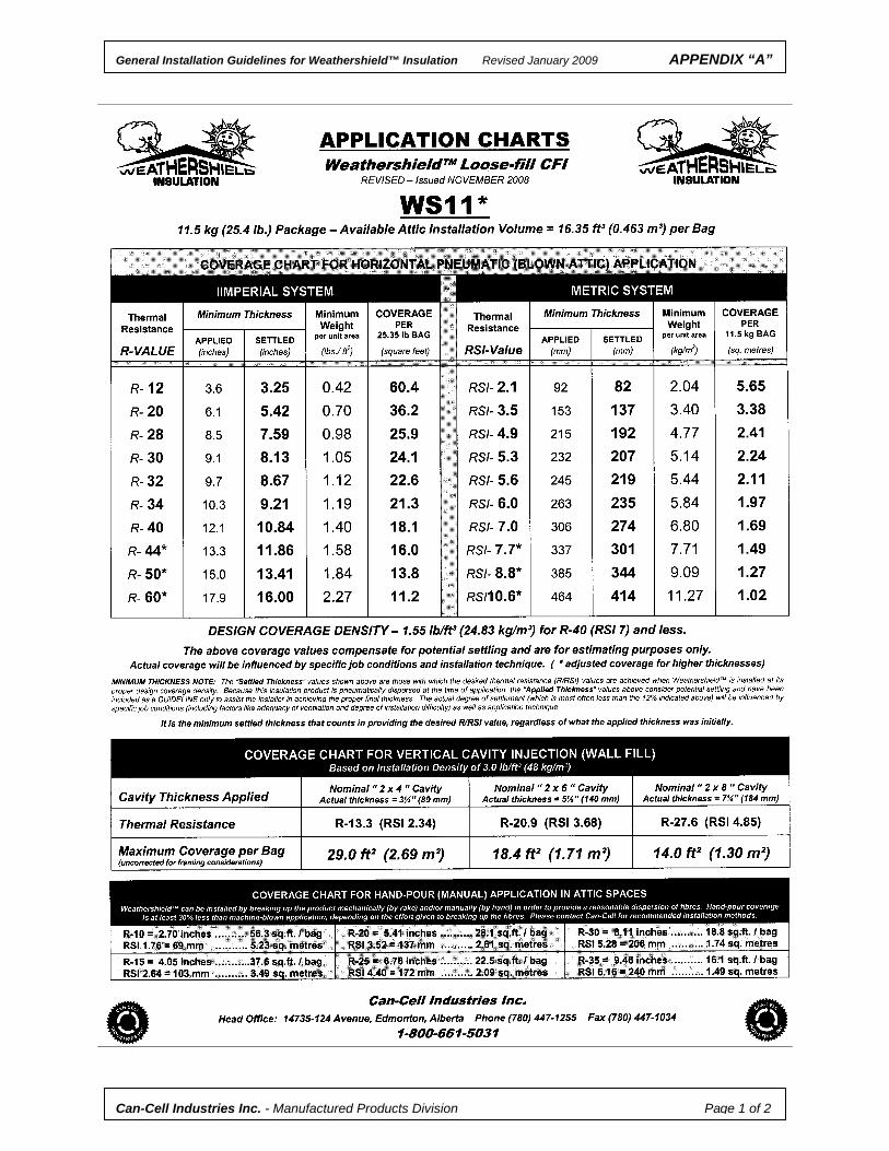
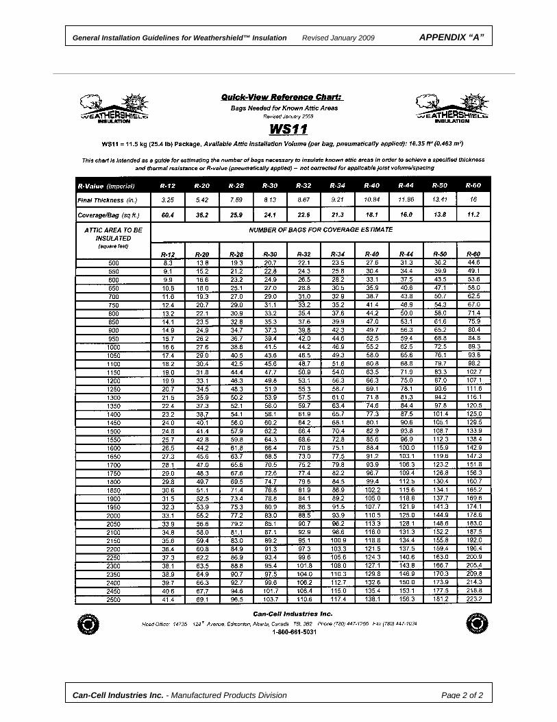
8. COVERAGE REQUIREMENTS
When installing Weathershield™, care must be taken to meet the area coverage shown on the chart printed on the package. It is very important that the proper coverage density be achieved for the particular application so that Weathershield™’s best performance may be realized.
Values for area coverage are calculated from Weathershield™’s design density and thermal resistivity (i.e. the R/RSI-value per unit thickness), determined and verified through testing, for a particular product application. Coverage charts are found in Appendix “A”. Area coverage values per bag are dependent on the package size – single-page application/coverage charts are available for each.
For horizontal (attic) installations, the “minimum thickness” or “settled thickness” listed is the final settled thickness required to provide a given R(RSI)-Value. The “initial/applied thickness” (that is, the thickness installed while insulating) will exceed this value in order to compensate for settlement and is intended as a guideline only – the actual degree of settlement depends on specific job conditions and installation technique. The bag count provides the total weight of material used and the actual area insulated is known (verified by measurements taken prior to insulating). The weight-per-unit-area values specified on the coverage chart must be followed to provide the specified R(RSI)-Value at Weathershield™’s design density.
A sidewall application chart is also available on the bag to indicate wall coverage requirements to be followed. Coverage densities are considerably higher for walls than for attics to ensure a complete fit of the cavity and resist settlement.
As previously stated, optimum coverage and product performance is provided by pneumatic (machine-blown) applications. Manual (hand-pour) methods are useful for small projects or repair applications. The do-it-yourself retrofit customer is advised to rent a small blowing machine for larger applications to get the best results. Recommendations for hand-pour application in attics are given in Appendix “B”.
Can-Cell Industries Inc. – Manufactured Products Division Page 12 of 18
General Installation Guidelines for Weathershield™ Insulation Revised January 2009
9. APPLICATION PROCEDURES
When installing insulation by pneumatic means, it is important to use the machine settings recommended by the machine’s manufacturer. In all such applications, it is recommended that the installer use a minimum of 100 feet (30 metres) of hose to help ensure maximized dispersion of the product. Optimum hose diameter varies with the type of application.
9.1 Attic & Ceiling Installations
Open Attic Spaces (new construction or retrofit)
- Markers, such as a cardboard ruler, should be placed wherever possible to indicate proper installation thickness. The more markers in place, the easier it will be to provide a consistent application.
- Machine air settings should be set low at the outset and then adjusted once application
begins. Material flow should be like water from a hose, falling between 4-6 feet (1.5 – 2m) from the end of the hose or nozzle. Start at the perimeter and work back towards the attic access. Material can be applied more evenly to the outer edges of the attic by using a rigid extension tube, which is removed when working in the centre of the attic.
- The application hose should be held parallel with the ceiling joists
whenever possible (or practical) at a height of 2-3 feet (0.6-0.9 m). This is so that the impact due to the trajectory of applied material does not contribute to excessive compaction of the product. Aiming too high or too low results in increased or variable density (and decreased or inconsistent coverage).
- Obstructions such as cross-framing may require the hose to be kept much closer to the
surface to direct material under them. Product should be blown on both sides of such obstructions in order to eliminate potential voids. Only where space limitations make it necessary should the stream of material be deflected by hand.
Enclosed Ceiling Cavities (Retrofitting Attic Floors)
- It must be established whether the cavities have existing batt insulation. Should batts fill the
whole cavity space, Can-Cell recommends against the installation of Weathershield™ to such cavities unless the batts can first be removed.
- If batts do not fill the cavity and allow a 2-3” space above them, Weathershield™ could be injected in over top of the batts (from the attic side) – the batts will compress somewhat as Weathershield™ fills the space. It should be noted that the presence of batts in the cavity would affect coverage estimations. See also Appendix “D”.
- Such cavities should be treated as horizontally placed walls and pneumatically injected using
a fill tube in each cavity. As the insulation fills the cavity, the fill tube is withdrawn. The air setting should be set as recommended by the machine manufacturer for sidewall application. Coverage will be proportional to that shown on the Weathershield™ sidewall application chart, depending on the cavity size and the package size of Weathershield™ being used.
Can-Cell Industries Inc. – Manufactured Products Division Page 13 of 18
General Installation Guidelines for Weathershield™ Insulation Revised January 2009
9.2 Wall Applications
New Construction
- Open wall cavities are usually either dry-injected through some type of retaining membrane, such as netting or polyethylene, or wet-spray applied from the interior side of the sidewall.
- Prior to installing Weathershield™, ensure the application equipment is adjusted to the
recommended setting as defined by the equipment manufacturer. It is important to note that the machine must be adjusted to deliver the insulation into the cavity under significantly higher pressures than what is used for attic applications. The purpose of this is to compress the material to a non-settling state.
- Cavities are filled by injecting Weathershield™ through one or more entry holes made along
the length of the cavity. If a one-hole method is used, the hose is lowered to within 12” (300 mm) of the bottom of the cavity through an entry hole made near the top of the cavity. The hose is slowly withdrawn up the cavity as the injected material is compressed around the end of the hose and the hose begins to plug off (indicated by a change in blower noise).
- If a multiple-hole method is used, the cavity is completely filled through an initial entry point located near the middle or top portion of the cavity. Additional insulation is then injected and packed into the cavity through subsequent entry holes evenly spaced along the cavity.
- The WallBAR™ dry-injection systems (product, equipment and retaining systems) are
proprietary. Can-Cell provides detailed instruction and special training programs for licensing their use. Spray application systems are also proprietary and are designed for use with specific products. Can-Cell’s instructions with regard to application equipment, its use, and amount of water to be applied must be followed explicitly. See Appendix “C” for further information.
- In spray applications, the interior of each wall cavity is lightly wetted (using a light water-only
spray) prior to applying sprayed product. This facilitates better adherence of the sprayed material to the interior surfaces of the cavity.
- Each cavity is spray-filled, starting from the bottom, using a fluid side-to-side motion (from stud to stud). Once the sprayed material thickness surpasses the stud face at the bottom, the hose and nozzle is elevated to make similar passes to build on it, continuing up the cavity until it is completed. The process is repeated for each cavity space.
- After spray-application, the insulation is levelled with the stud faces by using a screeding (surface-finishing) tool known as a “stud scrubber”, available through Can-Cell.
- The wall can be closed shortly after installation, even when a vapour barrier or other vapour retardant materials, such as some types of paints and vinyl wallcoverings, will be applied. Walls sprayed with less than 20% added moisture can be immediately closed. Walls sprayed with more than 20% added moisture might require a short drying period (usually 24-48 hours) under ventilated conditions.
Retrofit Application
- It must be established whether the cavities have existing batt insulation. Existing batts will interfere with an effective installation. Unless the batts are removed, do not install Weathershield™ or WallBAR™ to such cavities. See also Appendix “D”.
- Machine air settings should be as recommended by the machine manufacturer according to
the nozzle being used. Your Can-Cell representative can provide this information as well.
- Fill holes are to be drilled with a hole saw. Hole size can range between 1” and 2¼” (25-56mm) and is dependent on the filling method. Prior to filling, all cavities should be checked for obstructions with electrician’s fish tape, plumb bob or similar tool. Drill extra holes to access any isolated cavities found.
Can-Cell Industries Inc. – Manufactured Products Division Page 14 of 18
General Installation Guidelines for Weathershield™ Insulation Revised January 2009
- Density checks are recommended once the first few stud spaces are filled in order to ensure
the material is being installed properly.
- When filling smaller cavities through a single entry point using a fill tube, the fill tube is inserted into the cavity until it reaches within 12” (300 mm) of the top or bottom portion of the cavity. Fill tube size will depend on the size of hole that can be drilled. Possible entry points are:
– Through the bottom plate (from the basement or crawl space)
– Through the top plate (from the attic)
– Through the interior side (behind the baseboard or casing)
– Through the interior side (at drywall tape joint)
– Through the exterior siding (strip removed), drilling through sheathing
– Through the exterior, entering through soffit vent (removed) and drilling through the sub-siding or sheathing in soffit area.
- Weathershield™ is injected into the cavity until the area around the end of the fill tube is full,
then retracting the fill tube 12” (300 mm) at a time, allowing additional insulation to fill the void created.
- When filling cavities through two entry points, which is recommended for each 8-feet (2.4 m)
of stud space, location of the holes should not be more than 1-foot (0.3 m) from the top plate and 2-feet (0.6 m) from the bottom plate.
- Start with the bottom hole – insert the hose/nozzle and fill the area below the hole. The machine backpressure will indicate when the area is full so that the hose/nozzle can be retracted and adjusted for the areas at and above the hole.
- When two-thirds of the cavity is filled, remove the hose/nozzle from the bottom hole and place it in the top hole, repeating the action until the entire cavity is pressure-filled. Take extra care to ensure sufficient density is applied to the uppermost part of the cavity and its corners to ensure against settlement but not so dense as to detach the gypsum board on the interior.
- Entry for this method may be made from either the inside or outside depending on conditions, preference and whether existing insulation or a vapour barrier is present. Homes with shingle or lapped siding should be insulated from the interior side – drilling directly through siding is generally not recommended due to the difficulty in colour matching after. Exceptions would include wood siding that will be repainted following the installation. Homes with brick exteriors could have holes drilled in the mortar joints or, whenever possible, remove a single brick for each entry – return them and re-mortar once done.
- All holes should be closed with suitable plugs. Plugs applied to exterior entry holes in
sheathing should be properly sealed as well. 9.3 Sloped Ceilings & Flat Roofs:
- Installations of sloped ceiling and flat roof cavities are essentially the same as vertical wall applications. In new construction where cavities are still open, the WallBAR™ system is recommended and includes methods that conform to code requirements. See Appendix “C” for more information.
- In retrofit applications where existing sloped roof cavities are to be filled (and verified to be
empty), Weathershield™ may be used:
- Prior to installing new shingles, cut strips out of the roof sheathing and fill the exposed cavity with Weathershield™. Fasten the strips back into place and seal with pitch or suitable caulking and install new shingles. See Appendix “D” for further information.
- Remove the soffit and using a rigid 2” (50 mm) fill tube the length of the roof cavity and marked every 12” (300 mm), insert it to within 12” (300 mm) of the end of the cavity. Fill the cavity with Weathershield™ and retract the fill tube, in 12” (300 mm) intervals, the same as for attic floors. Replace the soffit.
Can-Cell Industries Inc. – Manufactured Products Division Page 15 of 18
General Installation Guidelines for Weathershield™ Insulation Revised January 2009
- In the case of very long cavities, such as a 20-foot (6 metre) cathedral ceiling, it is more practical to
remove shingles and sheathing at the ridge and inject Weathershield™ into the exposed cavities with the fill tube from there. The soffit end must be blocked to prevent material from filling it.
- The practice of completely filling these retrofit cavities with dense-pack CFI (Weathershield™
or WallBAR™), without the ventilated air space or vapour barrier required for new construction, provides maximum insulating value for a limited space. Can-Cell is not aware of any associated problems with this practice and will warrant Weathershield™’s service when properly installed.
- For retrofitting flat roof cavities, adapting the sloped ceiling method to enter cavities from the
outside through the fascia board applies. When repairs or renovations are required for tar and gravel roofs, entry can be made by temporarily removing strips cut in the sheathing – locate bracing and other obstacles within the cavities so that isolated cavities are not missed. Once cavities are insulated, the strip is replaced, sealed and the area can be resurfaced. See Appendix “D” for further information.
9.4 Windows & Doors:
The small cavities around windows and doors must be insulated. For new construction, this is covered under Section 7 (Preparation). In retrofit applications where these cavities are enclosed, it may be necessary and easier to fill them with foamed-in-place products by drilling and plugging the window casement itself. Sophisticated electronic stud-finders or infrared imaging devices are available to detect even the most elusive cavities so that none are missed.
9.5 Floors & Rim Joists:
Floors built over unheated basements or crawl spaces must be insulated. This includes floors of structures built on piers (such as some cottages). This can be achieved from the basement or crawl space side by creating cavities with netting and filling like an open sidewall.
- If enclosed cavities already exist and do not contain batt insulation, the attic floor method may be used, entering through from either above or below. If renovating the floor, entry holes could be drilled through the subfloor from above and plugged after insulating the cavity. Ensure all isolated cavities are located and filled.
- Sometimes the degree of cross bracing and blocking is high, requiring several holes to access all the isolated cavities. Instead, it may be necessary and more practical to cut strips from the subfloor to expose all cavities and insulate as described for flat roofs (see also Appendix “D”).
Perimeter rim joist areas of the home must be insulated. If the basement or crawl space is unheated, insulating the floor over it will include the rim joists areas (see above). If the basement or crawl space is heated, it is only necessary to insulate the rim joist areas of the perimeter, unless added acoustical control is required for the floor.
- From the underside, smaller cavities are created at the perimeter with netting and injected full with Weathershield™ (similar to above).
When acoustical control is required for the floor to reduce noise in the heated basement below, joist cavities are created from below with netting (after the rim joist areas are insulated) and injected with Weathershield™ – the cavities need not be completely filled for good acoustical control. Installations providing a minimum of 3½” (89 mm) are recommended.
- If enclosed cavities already exist and do not contain batt insulation, the attic floor method may be used to provide the desired amount of Weathershield™ in the main cavity but allowing the perimeter rim joist areas to pack full.
- If renovating the floor, entry holes could be drilled through the subfloor from above and plugged after insulating the cavity. Ensure all isolated cavities are located and filled.
- Sometimes the degree of cross bracing and blocking is high, requiring several holes to access all the isolated cavities. Instead, it may be necessary and more practical to cut strips from the subfloor to expose all cavities and insulate as described for flat roofs (see also Appendix “D”).
Can-Cell Industries Inc. – Manufactured Products Division Page 16 of 18
General Installation Guidelines for Weathershield™ Insulation Revised January 2009
10. EQUIPMENT 10.1 Insulating Machines:
Commercial Machine Function - The contents of the Weathershield™ package are manually placed into the feed hopper
where rotating paddles break up the material and automatically deliver it to the airlock chamber. This is an enclosed cylinder containing a rotor with several blades that form separate chambers within the cylinder.
- Blade rotation permits material to enter the chambers at a controlled rate and be injected into
the air stream without disruption of the pressure or flow of air.
- The blower supplies the airflow and pressure to move the material from the feeder into and through the hose.
- In the hose, the air stream turbulence and the length of time the material dwells in the hose
combine to further fluff the loosened material into a suitable form for delivery at the end of the hose.
For a given material, the speed of the airflow and the ratio of material quantity to air volume largely control coverage results. Machines have two basic controls to regulate these factors. The primary control is the throttle setting of the engine and the secondary control is the relief valve on the blower. Only experimentation with these settings will determine the proper adjustments needed to provide optimum coverage. For attic applications, a simple test for airflow and pressure is to hold the hose horizontally at a height of about 3-feet (1 m) while blowing the material. The blown insulation should fall gently onto the surface about 4-6 feet (1½ – 2 m) from the end of the hose. If the material bounces as it strikes the surface, or falls beyond 6-feet (2 m), first open the relief valve to allow some air pressure to escape and, if necessary, reduce the throttle setting to achieve the proper flow of material. For dense-pack applications, material should bounce as it strikes surfaces, should fall beyond 6-feet (2 m) and it would be relatively difficult to stop the low of air and material leaving the hose with your hand.
Feeder seals should be inspected regularly and replaced periodically to avoid air leakage, as this will interfere with control of the optimum flow of material. Rental Machines The smaller machines available to the do-it-yourself installer from building supply stores are usually of the through-blower type, which do not have an airlock or throttle adjustment. As such, material flow is not as well regulated and, since the blower operates at a constant speed, control is limited to air adjustment. These machines are considerably slower in terms of application rate but are suitable for smaller insulation jobs. Machines for Spray Application Only machines designed specifically for spray application are recommended but most commercial machine manufacturers build spray models as well. Spray machines differ from loose-fill machines in terms of airlock size, agitator design and speed, and material application rate. Rental (through-blower) machines are not suitable for any type of spray application.
Can-Cell Industries Inc. – Manufactured Products Division Page 17 of 18
General Installation Guidelines for Weathershield™ Insulation Revised January 2009
10.2 Delivery Hose & Nozzles:
Hose length, diameter, and condition are extremely important for the proper conditioning of any CFI product.
- A minimum length of 100’ (30 m) of hose is recommended for most loose-fill applications.
- A minimum of 200’ (60m) of hose is often recommended for spray applications.
Optimum hose diameter depends on the intended application:
- 2½ - 3” (65-75 mm) ID is recommended for open blow (attic) applications. - 2½” (65 mm) ID is recommended for sidewalls and cavities.
- 2” ID (50mm ID) is often recommended for spray applications.
- Damaged hose can affect the material flow and coverage of the product. Air leakage through
worn spots will reduce fluffing at the delivery end of the hose. Bent or kinked hose affects consistent material flow. Worn hose provides less effective fluffing of the product since it is the corrugated interior surface of good hose that helps create the turbulence to properly fluff the product and provide optimum coverage.
The various types of hose recommended for the application of CFI products are available through Can-Cell. Fill tubes, extension tubes, deflectors, reducers, and other types of nozzles (including spray nozzles and tips) that are recommended for use with Can-Cell’s CFI products are also available.
10.3 Maintenance:
The importance of well-maintained equipment in any installation cannot be over-emphasized in providing control of airflow, pressure and material delivery in order to achieve the best insulating job. Reduced coverage is most often due to worn feeder seals and/or hose, and not the product. A comprehensive maintenance inspection should be conducted regularly on all application equipment. Such activities should also be documented – a review of the number of bags of product blown between inspections may be useful in determining the expected life of machine parts, feeder seals and hose. The installer should refer to the equipment manufacturer’s recommendations for adjustments, settings and for maintenance requirements. Such information, including troubleshooting tips, is also available from Can-Cell.
General Installation Guidelines for Weathershield™ Insulation Revised January 2009
11. JOB SITE PLACARD
It is strongly recommended that all contractors provide their customers with a completed job site placard. The purpose of the card is to provide the customer with a permanent record of the materials used and the work performed and is often required to validate product warranties. For attic installations, this is often referred to as an “attic card”, filled out upon completion of the work by the installer. Placards typically contain the following information:
- Product (Name) and manufacturer
- Job Site Address
- Installation Date
- Homeowner’s (and/or builder’s) name
- Total Area Insulated (in square feet or square metres)
- Intended Thermal Resistance (R(RSI)-Value)
- Minimum Thickness (in inches or millimetres)
- Minimum Area Weight (in lb./sq.ft or kg/sq.m)
- Weight per Package (lb. or kg) and the number of packages used
- Name of Installation Company (including address, phone number, etc.)
- Printed name and signature of applicator (installer) The completed attic card should then be affixed to the building structure near the attic hatch or access.
Weathershield™ attic cards are available from Can-Cell.
Can-Cell Industries Inc. – Manufactured Products Division Page 18 of 18
General Installation Guidelines for Weathershield™ Insulation Revised January 2009 APPENDIX “A”
Can-Cell Industries Inc. - Manufactured Products Division Page 1 of 2
General Installation Guidelines for Weathershield™ Insulation Revised January 2009 APPENDIX “A”
Can-Cell Industries Inc. - Manufactured Products Division Page 2 of 2
General Installation Guidelines for Weathershield™ Insulation Revised January 2009 APPENDIX “B”
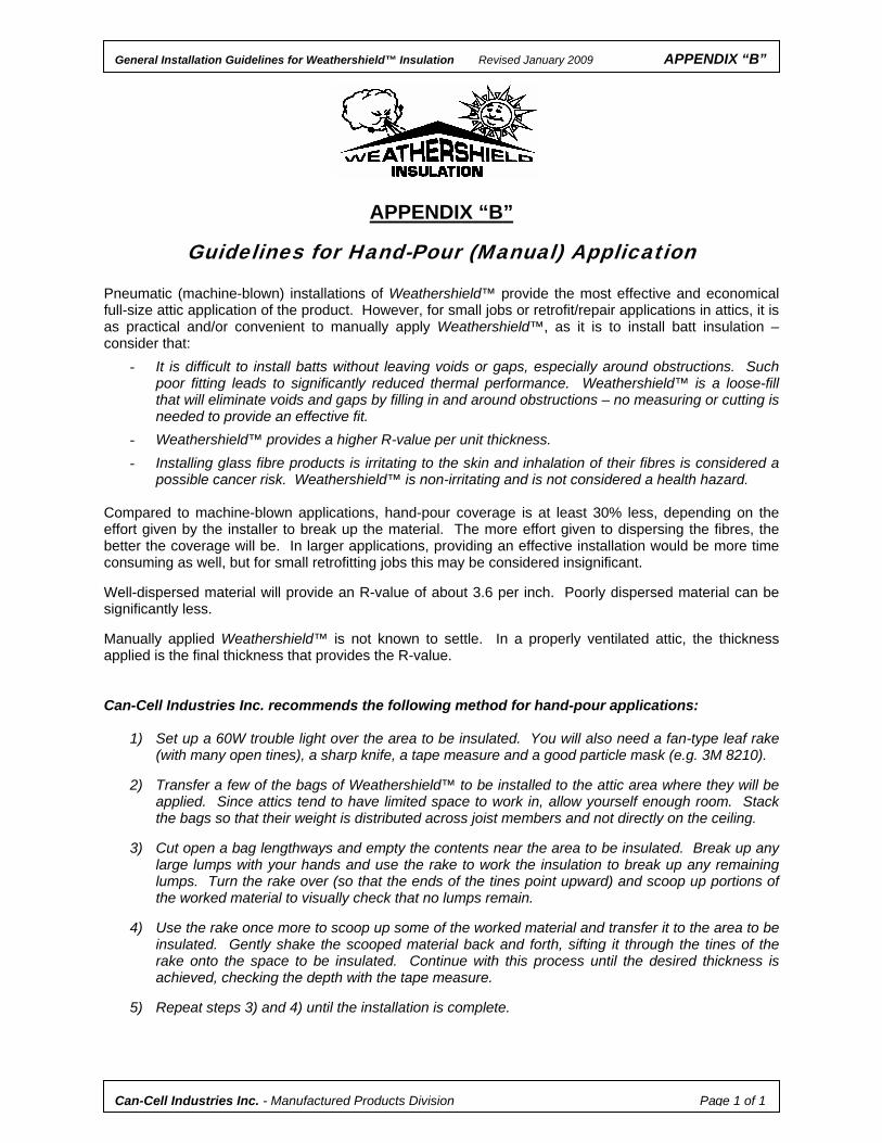
APPENDIX “B”
Guidelines for Hand-Pour (Manual) Application
Pneumatic (machine-blown) installations of Weathershield™ provide the most effective and economical full-size attic application of the product. However, for small jobs or retrofit/repair applications in attics, it is as practical and/or convenient to manually apply Weathershield™, as it is to install batt insulation – consider that:
- It is difficult to install batts without leaving voids or gaps, especially around obstructions. Such poor fitting leads to significantly reduced thermal performance. Weathershield™ is a loose-fill that will eliminate voids and gaps by filling in and around obstructions – no measuring or cutting is needed to provide an effective fit.
- Weathershield™ provides a higher R-value per unit thickness.
- Installing glass fibre products is irritating to the skin and inhalation of their fibres is considered a possible cancer risk. Weathershield™ is non-irritating and is not considered a health hazard.
Compared to machine-blown applications, hand-pour coverage is at least 30% less, depending on the effort given by the installer to break up the material. The more effort given to dispersing the fibres, the better the coverage will be. In larger applications, providing an effective installation would be more time consuming as well, but for small retrofitting jobs this may be considered insignificant. Well-dispersed material will provide an R-value of about 3.6 per inch. Poorly dispersed material can be significantly less. Manually applied Weathershield™ is not known to settle. In a properly ventilated attic, the thickness applied is the final thickness that provides the R-value. Can-Cell Industries Inc. recommends the following method for hand-pour applications:
1) Set up a 60W trouble light over the area to be insulated. You will also need a fan-type leaf rake (with many open tines), a sharp knife, a tape measure and a good particle mask (e.g. 3M 8210).
2) Transfer a few of the bags of Weathershield™ to be installed to the attic area where they will be
applied. Since attics tend to have limited space to work in, allow yourself enough room. Stack the bags so that their weight is distributed across joist members and not directly on the ceiling.
3) Cut open a bag lengthways and empty the contents near the area to be insulated. Break up any
large lumps with your hands and use the rake to work the insulation to break up any remaining lumps. Turn the rake over (so that the ends of the tines point upward) and scoop up portions of the worked material to visually check that no lumps remain.
4) Use the rake once more to scoop up some of the worked material and transfer it to the area to be
insulated. Gently shake the scooped material back and forth, sifting it through the tines of the rake onto the space to be insulated. Continue with this process until the desired thickness is achieved, checking the depth with the tape measure.
5) Repeat steps 3) and 4) until the installation is complete.
Can-Cell Industries Inc. - Manufactured Products Division Page 1 of 1
General Installation Guidelines for Weathershield™ Insulation Revised January 2009 APPENDIX “C”
APPENDIX “C”
Application Summary for WallBAR™ Insulation (Applicable to Licensed Applicators)
As the name implies, WallBAR™ is a product designed primarily for wall applications. It is also ideal for sloped/cathedral ceilings, rim joists and stabilized attics. WallBAR™ contains an internal adhesive that is activated by ambient or applied moisture to provide additional resistance to settlement when properly installed in wall assemblies. WallBAR™ may be used in new construction, employing retaining membranes in application to open cavities regardless of slope. WallBAR™ is also suitable for dry-injection to any enclosed cavity (for retrofit applications).
WallBAR™ may be installed only under a licensing agreement with Can-Cell Industries Inc. WALL ASSEMBLIES
In new construction, WallBAR™ can be applied to open sidewall cavities in two ways. The first and most common method involves applying a retaining membrane to the interior stud faces and dry-injecting WallBAR™ into the cavity formed. The retaining membrane may be permeable, such as WallNET fabric netting, or non-permeable, such as polyethylene. The second method is spray-applying WallBAR™ (with water only) directly into and filling the open cavity and screeding the surface flush with the stud faces – once partially dry, the cavity can be enclosed. Interior walls (partywalls) can be partially wet-sprayed to provide acoustical control.
In retrofit applications, any enclosed cavity may be dry-injected with WallBAR™, provided the cavities are empty or existing insulation is first removed (the same as for Weathershield™ - see Appendix “D”). SLOPED/CATHEDRAL CEILINGS
In new construction (conforming to the NBC), using insulation stops, air chutes or a netted space provides a continuous airspace above the insulation. The cavity is formed with netting across the interior joist face and WallBAR™ is dry-injected in stages (from lower wall to higher wall or peak) with entry holes no further than 10’ (3 m) apart to ensure even density distribution. Cavities must not be overfilled in order to allow easy installation of gypsum board after. One method to help prevent overfilling problems is to install polyethylene and 1x2 or 1x3 strapping every 2’ (0.6 m) across joist facing to compensate for bulging.
In retrofit applications, existing batt insulation in sloped ceiling cavities must be removed prior to insulating unless they occupy two-thirds or less of the cavity space. WallBAR™ can be injected over top of the batts. Methods are described in Appendix D. The cavities are dense-packed (filled completely, allowing no airspace) with WallBAR™.
Retrofitting flat roofs with WallBAR™ is much the same as for Weathershield™ (see Appendix D). PERIMETER RIM JOISTS
Cavities are created with netting and dry-injected with WallBAR™. STABILIZED ATTICS
WallBAR™ may also be applied with moisture (misted water) in horizontal/blown applications at a final dry density of 22-23 kg/m³ (about 1.4 lb/ft³). The internal binder is immediately activated to provide maximum resistance to settlement. This application is also suitable for sloped areas exceeding 4.5:12. Details regarding specific installation procedures are found in the WallBAR™ Installation Manual (available only to licensed dealers).
Can-Cell Industries Inc. - Manufactured Products Division Page 1 of 1
General Installation Guidelines for Weathershield™ Insulation Revised January 2009 APPENDIX “D”
APPENDIX “D”
Alternatives for Retrofitting Sidewalls and Ceiling Cavities In many retrofit cases, the cavities to be re-insulated contain some form of insulation, often batt-type insulation. Can-Cell Industries Inc. does not recommend the installation of Weathershield™ in wall cavities unless existing batts can first be removed. Some exceptions can be made in retrofitting ceiling cavities. The following methods are suggested as guidelines in alternative retrofitting where existing batt insulation is encountered and is to be replaced with Weathershield™ (or WallBAR™). SIDEWALLS
When exterior renovations are to be done (such as re-siding or installing some other new exterior finish) and the old finish is removed, a strip of sheathing can be temporarily taken out of the centre of the wall and the existing batt insulation can be removed. The opened space is netted, the exposed cavities filled with Weathershield™ or WallBAR™, and the strip is put back and sealed. The new exterior finish is then applied. Recommendations are as follows:
1. Once the old exterior finish is removed, cut a horizontal strip in the sheathing 12” wide (depending on the framing and exterior finish) in the centre of the wall cavity and remove it.
- A circular saw is most often used. Set the saw blade depth to the thickness of the sheathing (if known) or a maximum of ½”. Most plywood sheathing is not likely to exceed ½” thickness in homes built in the 1960’s or later. Older homes may have other types and thicknesses of sheathing (such as ¾” shiplap) and may not require cutting to remove it.
- Whenever possible, a wider strip (14”-16”) can be cut for greater ease of batt removal and inspection. This also improves the manoeuvrability of the hose to allow for a more effective installation.
2. Remove the existing batt insulation.
3. Visually inspect each cavity to ensure all pieces of the batts are removed and that any isolated
cavities are detected.
- Depending on the requirements of the customer, the small cavities above window frames may be left with existing batt insulation – otherwise an additional short strip must be cut to fill such cavities. It is often more practical to leave these cavities alone unless they are known to be empty.
- Verify the length, width and thickness of the cavity to ensure coverage calculations will be correct. 4. Cut a strip of netting about 2” wider than the width of the sheathing strip. Fold about 1” over on
top edge of netting strip and staple to the exposed stud faces with the folded edge tight up against the upper edge of the sheathing opening. Ensure netting is pulled tight as you go. Fold the bottom edge of the netting strip so it is tight against the bottom edge of the sheathing opening and secure with staples.
5. Cut an entry slit in the netting for each cavity for the delivery hose. In addition to the
recommended 150’ minimum length of hose, a 3’ to 3.5’ section of rigid or semi-rigid hose should be attached to the delivery end.
Can-Cell Industries Inc. - Manufactured Products Division Page 1 of 3
General Installation Guidelines for Weathershield™ Insulation Revised January 2009 APPENDIX “D”
Can-Cell Industries Inc. - Manufactured Products Division Page 2 of 3
6. Insert rigid hose to the bottom of the cavity and inject Weathershield™ or WallBAR™ until it fills the cavity up to the netting, retracting the nozzle about 12” at a time.
7. Remove enough hose to turn it upwards and re-insert to the top corners of the upper half of cavity. Proper attention must be given to pack each of the top corners of the cavity to ensure against settlement. Once corners are packed, retract nozzle about 12” at a time.
- It is important that proper installation density be achieved (i.e. 3.0-3.5 lb/ft³, 48-56 kg/m³) to properly resist settlement, but not too much so that the interior finish is compromised. Ensure the proper air setting and material volume is used to avoid dislocating gypsum board on the interior.
8. Remove enough hose to pack by “jabbing” the central area behind the netting and stop the installation.
9. Repeat steps 6-8 for the remaining cavities.
10. Roll the netting of each filled cavity to eliminate bulging.
11. Put the strip of sheathing back into place and fasten, including the strip of building paper or house
wrap that may have been there. Apply exterior caulking to the cut lines and finish with sheathing tape to seal the job.
12. The new exterior finish can then be installed.
When the exterior finish is siding and is not to be replaced with new siding, the existing siding can be partially removed so that the sheathing strip can be cut. When removal is not possible, cut through the siding (at an edge or shadow line) and sheathing all at once. Once Weathershield™ or WallBAR™ has been installed, the netting is rolled to eliminate bulges and the sheathing is replaced, fastened and sealed and the siding replaced and sealed. When the interior finish is to be renovated, it is possible to retrofit the sidewall cavities from the interior side in a similar manner to the above. A 12” strip of gypsum board is cut from the centre of the wall and the existing batt insulation is removed. Once the cavities are inspected for completeness of the removal and isolated cavities are located, the space opened is netted and filled with Weathershield™ or WallBAR™, and the strip is replaced, sealed and patched with drywall compound in the normal manner. The interior is then repainted, wallpapered or otherwise refinished. SLOPED ROOFS (CATHEDRAL CEILINGS) When enclosed sloped roof cavities containing existing batt insulation are to be retrofitted, the best method involves cutting a strip out of the roof sheathing and removing the batts first. Alternatively, if the existing batts fill only two-thirds or less of the cavity, they may be left in place and Weathershield™ (or WallBAR™) injected over top of them. It is recommended that this only be done when completely replacing the roofing materials. Due to blocking between some joists creating isolated cavities, more than one strip may need to be cut to ensure that all cavities in the roof space are considered. Once the old roofing finish is removed, a 12” strip can be cut out of the sheathing across all joist cavities. Once the existing batt insulation is removed, the cavities must be visually inspected to determine where blocking (and isolated cavities) exist. Additional strips are cut to expose any isolated cavities. The strip opening is netted and the cavities are injected full with Weathershield™ or WallBAR™ – once again it is important to install the proper density (3.0-3.5 lb/ft³, 48-56 kg/m³) so that overfilling does not compromise the interior finish. The netting is rolled to eliminate bulges and the sheathing strip put back, fastened, caulked and sealed. The new roofing materials can then be installed.
General Installation Guidelines for Weathershield™ Insulation Revised January 2009 APPENDIX “D”
Can-Cell Industries Inc. - Manufactured Products Division Page 3 of 3
When the roof finish is not to be repaired or replaced, it is still possible to retrofit roofs that have existing batt insulation, provided that a 2-3” continuous airspace is available above the batts in the cavities (that is, no blocking exists to create isolated cavities). In such cases, a 2½” hole may be drilled at the end of each joist space from the outside. A 2”-diameter extension tube, the full length of the joist space, is inserted along the top of the interior (above the batts) to the end of the cavity. Weathershield™ or WallBAR™ is then pneumatically injected, compressing the batt and filling the space as the fill tube is retracted 12” at a time. It is important to ensure that installation density not exceed 3.5 lb/ft³ (56 kg/m³) so that the interior ceiling/finish is not compromised. Once all cavities are filled, holes can then be sealed with suitable plugs and caulked. Can-Cell Industries Inc. warrants that the practice of completely filling (dense-packing) sloped roof cavities with Weathershield™ or WallBAR™ – that is, leaving no ventilated airspace, even in cavities without a vapour barrier – will not contribute to moisture problems in the areas so insulated, provided that the roof membrane remains intact. Should the roof membrane lose its integrity and leak, soaking the insulation material, this warranty shall be void. FLAT ROOF CAVITIES Enclosed flat roof cavities with existing batt insulation can be retrofitted much the same way as sloped roofs. Prior to replacing the tar-and-gravel roof finish, the roof cavities are partially exposed by cutting a strip in the roof sheathing and removing the batt insulation. Additional strips may be necessary when inspection detects blocking (isolated cavities). The exposed parts of the cavities are netted and injected with Weathershield™ or WallBAR™, and the sheathing strip put back, fastened and sealed. The roof can then be refinished. When the roof finish is not to be repaired or replaced, it is still possible to retrofit roofs that have existing batt insulation, provided that a 2-3” continuous airspace is available above the batts in the cavities (that is, no blocking exists to create isolated cavities). In such cases, a 2½” hole may be drilled at the end of each joist space from the outside. A 2”-diameter extension tube, the full length of the joist space, is inserted along the top of the interior (above the batts) to the end of the cavity. Weathershield™ or WallBAR™ is then pneumatically injected, compressing the batt and filling the space as the fill tube is retracted 12” at a time. It is important to ensure that installation density not exceed 3.5 lb/ft³ (56 kg/m³) so that the interior ceiling/finish is not compromised. Once all cavities are filled, holes can then be sealed with suitable plugs and caulked. Can-Cell Industries Inc. warrants that the practice of completely filling (dense-packing) sloped roof cavities with Weathershield™ or WallBAR™ – that is, leaving no ventilated airspace, even in cavities without a vapour barrier – will not contribute to moisture problems in the areas so insulated, provided that the roof membrane remains intact. Should the roof membrane lose its integrity and leak, soaking the insulation material, this warranty shall be void.