Embed Size (px)
Citation preview
GeneralSpecifications
Simple parameter settings: Frequentlyused selections grouped together in a
quickaccess format decreases commissioning time. Clear, concise indicator: Simultaneous flow rate or temperature (Option /MV)
and total flow rate along with process diagnosis conveniently displayed. Dual output for analog / pulse: Simultaneous output for flow rate or temperature
(Option /MV) and pulse. Alarm output, status output (Flow switch): An alarm signal output, in case alarm occurs. No moving parts stainless steel detector: High durable and safe. Remote cable length 30 m maximum. ATEX / FM flame (explosion) proof / intrinsically safe
approval Communication function includes *FOUNDATION
Fieldbus, BRAIN and *HART protocol.Refer to GS 01F06F00-01E for Fieldbus communication type when marked with “#”.* FOUNDATION is a registered trade mark of FOUNDATION Fieldbus.* HART is a registered trade mark of the HART
Communication Foundation.
CONTENTS
Features P. 1
Standard Specifications P. 2
Model and SuffixCode P. 5
Option Spec for General Use P. 8
Option Spec for Hazardous Use P. 10
Option Spec for MultiVariable Type (Option) P. 12
Option Spec for Reduced Bore type (Option) P. 13
Option Spec for Dual Calibrated DY (Option) P. 13
Sizing P. 15
Remarks on Installation P. 20
External Dimensions P. 23
Ordering Instructions P. 34
Model DYModel DYAVortex Flowmeter
GS 01R06A0001EE© Copyright Dec. 2000 (RYG)
10th Edition December 2015 (RYG)
Based on the field proven technologyBy the unique SSP (Spectral Signal Processing)* technology, digitalYEWFLO provides high accuracy and stability, even in harsh process conditions. Combined with high reliability and robust design, it delivers improvements in plant efficiency and reduce operating costs.digitalYEWFLO MultiVariable Type (option: /MV) with built in temperature sensor, temperature measurement and mass flow calculation is available.digitalYEWFLO Reduced Bore Type (option: /R1) Concentric reduced bore piping diameter integrated in casted construction. digitalYEWFLO Dual Calibration Type (option /DC1, /DC2). Integrated DualSens solution for your safety applications.
* SSP is YOKOGAWA’s original technology for digital signal processing.
FEATURES New functions with SSP (Spectral Signal Processing)
technology: SSP is built into the powerful electronics of digital
YEWFLO. SSP analyses the fluid conditions inside digitalYEWFLO and uses the data to automatically select the optimum adjustment for the application, providing features never before realized in a vortex flowmeter.
SSP accurately senses vortices in the low flow range, providing outstanding flow stability.
Advanced Selfdiagnostics: The application condition, such as high pipeline vibration and abnormal flow, is predicted and indicated. High Accuracy: ±0.75% of Reading (Liquid) [±0.5% of Reading: Typical Accuracy/NonGuaranteed] ±1% of Reading (Gas, Steam) Wide Process Temperature Range: High temperature version up to 450 °C
Model DYNRemote Type Detector
Model DYARemote Type Converter
Model DYD, DYEIntegral Type
Model DY/R1Reduced Bore Type
Rota Yokogawa GmbH & Co. KGRheinstr. 8D79664 WehrGermany
GS 01R06A0001EE
2
All Rights Reserved. Copyright © 2000, Rota YokogawaGS 01R06A00-01E-E 10th edition, December 14, 2015-00
MULTI-VARIABLE OPTION (/MV) digitalYEWFLO with built in temperature sensor (Pt1000) in the vortex shedder bar. Temperature measurement and mass flow calcula tion by temperature is available. (Refer to P.12) digitalYEWFLO with built in steam trend, mass
measurement of saturated steam and super heated steam (mass flow calculation)
Accuracy of digitalYEWFLO MultiVariable type is ±0.5 % of rate for temperature measurement, ±2% of rate for mass flow calculation (saturated steam).
DUAL CALIBRATED OPTION (/DC1; /DC2)Dual bolted calibration and disassembly before shipment: improves flexibility of installation improves safety by redundant installation possibility accuracy is equal to single installation
REDUCED BORE OPTION (/R1)Integrated and casting construction with concentric reduced bore piping: reduces installation costs and improves safety:
Expansion of measurement range into low flow rate regions
reduces costs for easy replacement: The same facetoface dimension as standard type.
STANDARD SPECIFICATIONS
Performance SpecificationsFluid to be Measured:
Liquid, Gas, Steam (Avoid Multiphase Flow and Sticky Fluids)
Measuring Flow Rates: Refer to Table 6 10Accuracy: ±0.75 % of Reading (Liquid) ±1 % of Reading (Gas, Steam) Refer to page 16Repeatability: ± 0.2 % of ReadingCalibration:
This flowmeter is factorycalibrated using a water flow facility.Temperature measurement test and flow calibration by water flow when MultiVariable Type is selected.
Normal Operating ConditionFor hazardous area applications the limitations in “Option Spec for Hazardous Use” page 10 11 apply.
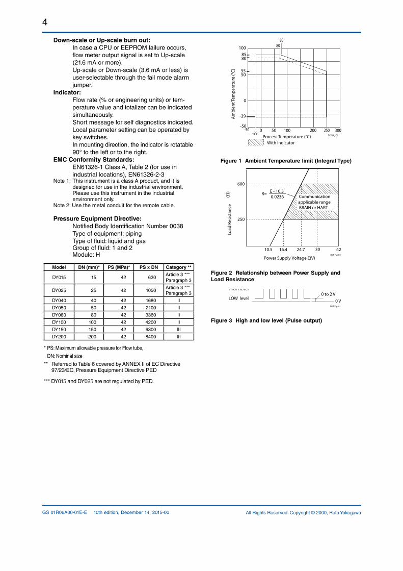
Process Temperature Range:–29 to 250 °C (general)–29 to 450 °C (High Process Temperature Version: option /HT)When MultiVariable type is selected, refer to P.12Refer to Figure 1 for integral converter type.
Process Pressure Limit:–0.1MPa (–1 bar) to flange rating.
Ambient Temperature Range: –29 to 85 °C ( Remote type detector)–40 to 85 °C (Remote type converter)–29 to 85 °C (Integral type, refer to Figure 1)–29 to 80 °C ( Integral type with Indicator,
refer to Figure 1)–30 to 80 °C ( Remote type converter with
Indicator)
Ambient Humidity : 5 to 100% RH (at 40 °C) (No Condensation)Power Supply Voltage (#):
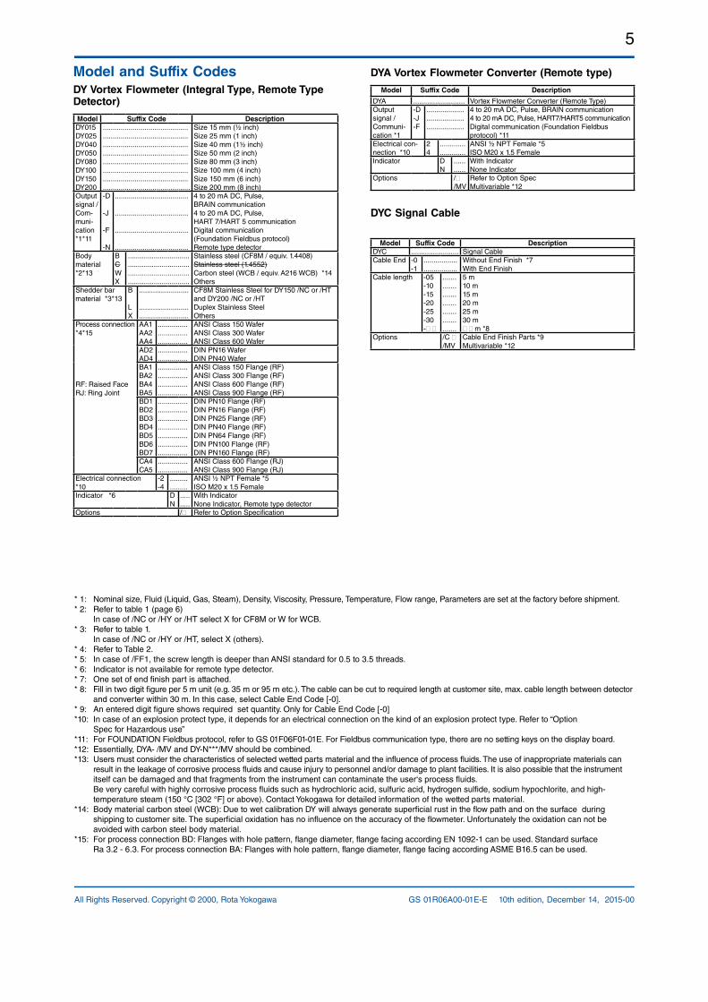
10.5 to 42 V DC 10.5 to 30 V DC (Lightning Protector: option)
(Refer to Figure 2 ; Relationship Between Power Supply Voltage and Load Resistance
Mechanical SpecificationsMaterial (General Type):
Refer to Table 1:Body/Flanges: CF8M casting stainless steel (equiv. 1.4408) WCB casting carbon steel ASTMA216WCB CW12MW (equiv. Hastelloy C276) on demand only Hastelloy is a registered trademark of Haynes
International Inc.Shedder bar: 1.4462 duplex stainless steel (DY015) 1.4517 duplex stainless steel CW12MW (equiv. Hastelloy C276)Gasket: refer to table 1NonWetted Parts: Housing (Case, Cover): Aluminum alloy JIS ADC12 Name Plate: Stainless steel JIS SUS304 DYA Mounting Bracket for 2´´ pipe´: Stainless Steel 304/1.4301
Coating Color:Converter case, cover: Deep sea moss green (Munsell 0.6GY 3.1/2.0) (Polyurethane corrosionresistant coating)
Degree of Protection: IP66/IP67 (IEC 60529), Type 4X (NEMA 250) Hazardous Area Classifications (#):
Refer to item “Option Spec for Hazardous Use”Electrical Connection:
ANSI 1/2 NPT female,ISO M20 x 1.5 female
Signal Cable:Model DYC cable, used for remote detector and converter.Max. length: 30 m.Outer Sheath Material: Heat resisting polyethyene Durable Temperature: –40 to 150 °C
Weight:Refer to item “External Dimensions”.
Mounting:Integral type or Remote type detector:
Flange mounting or wafer mounting by flange adjacent to the pipeline.
Remote type converter: 2 inch pipe mounting.
3
All Rights Reserved. Copyright © 2000, Rota Yokogawa GS 01R06A00-01E-E 10th edition, December 14, 2015-00
Electrical Specifications**: Pulse output, alarm output and status output use
the common terminal, therefore these functions
are not used simultaneously.
Output Signal (#): Dual output (both analog and transistor contact output can be obtained simultaneously). In this case refer to the item “Remarks on installation” for power supply and pulse output wiring.
Analog: 4 to 20 mA DC, 2wire system.Transistor Contact Output**:
Open collector, 3wire system.Pulse, alarm, status output are selected by parameter setting.Contact rating: 10.5 to 30 V DC, 120 mA DC*1
Low level: 0 to 2 V DC. (refer to Figure3) *1: 10.5 to 30 V DC. 80 mA DC for ATEX Intrinsi
cally Safe Approval (/KS2) Communication Requirement:
Communication Signal (#): BRAIN or HART communication signal (superimposed on a 4 to 20 mA DC signal)Conditions of Communication Line: Load Resistance: 250 to 600 Ω (including cable resistance). Refer to Figure 2. Supply Voltage: 16.4 to 42 V DC for digital communications
BRAIN and HART protocols (16.4 to 30 V DC for intrinsically safe type).
Refer to Figure 2. Distances to other Power Line: 15 cm or
more (Parallel wiring should be avoided.)BRAIN: Communication Distance: Up to 2 km, when polyethylene insulated PVCsheathed cables (CEV cables) are
used. Communication distance varies depending on type of cable used and wiring. Load Capacitance: 0.22 µF or less Load Inductance: 3.3 mH or less Input Impedance of communicating device: 10 kΩ or more at 2.4 kHz
Selection of HART 5 / HART 7Output signal code J
Ordering information Specify „5“ Specify „7“
HART Protocol Revision HART 5 HART 7
Selection guide
Requirement for HART 7 functio
nalityNo
YESBe sure to confirm the
protocol revision of the HART configuration
tool shown in *1
Other conditions
Available to switch to HART 7 protocol after
delivery by userconfiguration
Remarks *1 *1
*1 HART protocol revision for the device and HART configuration tool HART7 communication is supported by FieldMate R2.02 or later. Parameter will be programmed according
HART 5, then switched to HART 7. HART protocol revision and availability:
Protocol revisionsupported by HART
configuration tool
5 7
DY or DYA HART 5 Available Available
DY or DYA HART 7 Not Available Available
Note: Protocol revision supported by HART configuration tool must be the same or higher than that of the digitalYEWFLO.
Functions:Damping Time Constant: 0 to 99 s (63 % response time)Note: Delay time is 0.5 s
Analog output circuit time constant is 0.3 sPulse Output Function**:
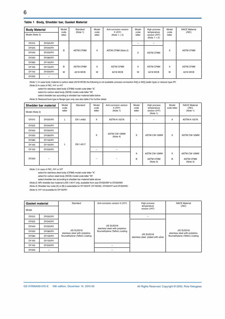
Pulse output is selected from scaled pulse, unscaled pulse, frequency (number of pulses output per second at 100% of output).Pulse frequency: Max 10 kHzDuty cycles: Approx. 50 % (1:2 to 2:1)
Self -diagnostics and Alarm Output**:In case alarm occurs (over range output signal, EEPROM error, vibration noise, abnormal conditions such as clogging or bubbles), an alarm signal is output and is indicated.The alarm signal output goes from close (ON) to open (OFF) during alarming.
Analog Output Function:Analog output is selected from flow rate and temperature value when option code /MV is selected.
Status Output Function**: Flow Switch:
In case flow rate decreases under the flow set value, a status signal is output. Status signal output mode can reverse (ON/ OFF) .
Data Security During Power Failure: Data (parameter, totalizer value, etc.) storage by EEPROM. No backup battery required.
Correction: Instrument Error Correction:
Vortex flow meter instrument errors can be corrected by segment approximations.
Reynolds Number Correction: Output error at Reynolds number 20000 or
less is corrected by using fivebreakpoint linesegment approximation.
Gas Expansion Correction: When measuring a compressible gas and steam, this expansion factor is useful to correct the error at high velocity of flow (35 m/s or more).
4
All Rights Reserved. Copyright © 2000, Rota YokogawaGS 01R06A00-01E-E 10th edition, December 14, 2015-00
Down-scale or Up-scale burn out:In case a CPU or EEPROM failure occurs, flow meter output signal is set to Upscale (21.6 mA or more).Upscale or Downscale (3.6 mA or less) is userselectable through the fail mode alarm jumper.
Indicator:Flow rate (% or engineering units) or temperature value and totalizer can be indicated simultaneously. Short message for self diagnostics indicated.Local parameter setting can be operated by key switches. In mounting direction, the indicator is rotatable 90° to the left or to the right.
EMC Conformity Standards: EN613261 Class A, Table 2 (for use in
industrial locations), EN6132623Note 1: This instrument is a class A product, and it is
designed for use in the industrial environment. Please use this instrument in the industrial environment only.Note 2: Use the metal conduit for the remote cable.
Pressure Equipment Directive: Notified Body Identification Number 0038 Type of equipment: piping Type of fluid: liquid and gas Group of fluid: 1 and 2 Module: H
Model DN (mm)* PS (MPa)* PS x DN Category **
DY015 15 42 630Article 3 ***Paragraph 3
DY025 25 42 1050Article 3 ***Paragraph 3
DY040 40 42 1680 II
DY050 50 42 2100 II
DY080 80 42 3360 II
DY100 100 42 4200 II
DY150 150 42 6300 III
DY200 200 42 8400 III
* PS: Maximum allowable pressure for Flow tube,
DN: Nominal size
** Referred to Table 6 covered by ANNEX II of EC Directive 97/23/EC, Pressure Equipment Directive PED
*** DY015 and DY025 are not regulated by PED.
200100500-50-29
100
50
0
300Process Temperature (°C)
With Indicator
Am
bien
t Tem
pera
ture
(°C)
85
-50250
85
-29
80
80
DYF Fig-01
55
Without Indicator
Figure 1 Ambient Temperature limit (Integral Type)
Figure 2 Relationship between Power Supply and Load Resistance
Figure 3 High and low level (Pulse output)
R= E - 10.50.0236
250
600
10.5 16.4 24.7 42
Power Supply Voltage E(V)
(Ω)
Communicationapplicable rangeBRAIN or HART
30
Load
Res
ista
nce
DYF Fig-02
HIGH level
LOW level 0 V0 to 2 V
DYF Fig-03
5
All Rights Reserved. Copyright © 2000, Rota Yokogawa GS 01R06A00-01E-E 10th edition, December 14, 2015-00
Model and Suffix CodesDY Vortex Flowmeter (Integral Type, Remote Type Detector)
Model Suffix Code DescriptionDY015DY025DY040DY050DY080DY100DY150DY200
...........................................
...........................................
...........................................
...........................................
...........................................
...........................................
...........................................
............................................
Size 15 mm (½ inch)Size 25 mm (1 inch)Size 40 mm (1½ inch)Size 50 mm (2 inch)Size 80 mm (3 inch)Size 100 mm (4 inch)Size 150 mm (6 inch)Size 200 mm (8 inch)
Output signal / Communication*1*11
D
J
F
N
.....................................
.....................................
.....................................
.....................................
4 to 20 mA DC, Pulse,BRAIN communication4 to 20 mA DC, Pulse,HART 7/HART 5 communicationDigital communication(Foundation Fieldbus protocol)Remote type detector
Body material*2*13
BCWX
...............................
...............................
...............................
...............................
Stainless steel (CF8M / equiv. 1.4408)Stainless steel (1.4552)Carbon steel (WCB / equiv. A216 WCB) *14Others
Shedder bar material *3*13
B
LX
.........................
.........................
.........................
CF8M Stainless Steel for DY150 /NC or /HT and DY200 /NC or /HT Duplex Stainless SteelOthers
Process connection*4*15
RF: Raised FaceRJ: Ring Joint
AA1AA2AA4
...............
...............
...............
ANSI Class 150 WaferANSI Class 300 WaferANSI Class 600 Wafer
AD2AD4
...............
...............DIN PN16 WaferDIN PN40 Wafer
BA1BA2BA4BA5
...............
...............
...............
...............
ANSI Class 150 Flange (RF)ANSI Class 300 Flange (RF)ANSI Class 600 Flange (RF)ANSI Class 900 Flange (RF)
BD1BD2BD3BD4BD5BD6BD7
...............
...............
...............
...............
...............
...............
...............
DIN PN10 Flange (RF)DIN PN16 Flange (RF)DIN PN25 Flange (RF)DIN PN40 Flange (RF)DIN PN64 Flange (RF)DIN PN100 Flange (RF)DIN PN160 Flange (RF)
CA4CA5
...............
...............ANSI Class 600 Flange (RJ)ANSI Class 900 Flange (RJ)
Electrical connection *10
24
.........
.........ANSI ½ NPT Female *5ISO M20 x 1.5 Female
Indicator *6 DN
.....
.....With IndicatorNone Indicator, Remote type detector
Options / Refer to Option Specification
DYA Vortex Flowmeter Converter (Remote type)
Model Suffix Code Description
DYA .......................... Vortex Flowmeter Converter (Remote Type)Output signal / Communication *1
DJF
...................
...................
...................
4 to 20 mA DC, Pulse, BRAIN communication4 to 20 mA DC, Pulse, HART7/HART5 communicationDigital communication (Foundation Fieldbus protocol) *11
Electrical connection *10
24
.............
.............ANSI ½ NPT Female *5ISO M20 x 1.5 Female
Indicator DN
......
......With IndicatorNone Indicator
Options //MV
Refer to Option SpecMultivariable *12
DYC Signal Cable
Model Suffix Code DescriptionDYC ........................ Signal CableCable End 0
1..................................
Without End Finish *7With End Finish
Cable length 051015202530
.......
.......
.......
.......
.......
.......
.......
5 m10 m15 m20 m25 m30 m m *8
Options /C /MV
Cable End Finish Parts *9Multivariable *12
* 1: Nominal size, Fluid (Liquid, Gas, Steam), Density, Viscosity, Pressure, Temperature, Flow range, Parameters are set at the factory before shipment.* 2: Refer to table 1 (page 6) In case of /NC or /HY or /HT select X for CF8M or W for WCB.* 3: Refer to table 1. In case of /NC or /HY or /HT, select X (others). * 4: Refer to Table 2.* 5: In case of /FF1, the screw length is deeper than ANSI standard for 0.5 to 3.5 threads.* 6: Indicator is not available for remote type detector.* 7: One set of end finish part is attached.* 8: Fill in two digit figure per 5 m unit (e.g. 35 m or 95 m etc.). The cable can be cut to required length at customer site, max. cable length between detector and converter within 30 m. In this case, select Cable End Code [0].* 9: An entered digit figure shows required set quantity. Only for Cable End Code [0]*10: In case of an explosion protect type, it depends for an electrical connection on the kind of an explosion protect type. Refer to “Option Spec for Hazardous use” *11: For FOUNDATION Fieldbus protocol, refer to GS 01F06F0101E. For Fieldbus communication type, there are no setting keys on the display board.*12: Essentially, DYA /MV and DYN***/MV should be combined. *13: Users must consider the characteristics of selected wetted parts material and the influence of process fluids. The use of inappropriate materials can result in the leakage of corrosive process fluids and cause injury to personnel and/or damage to plant facilities. It is also possible that the instrument itself can be damaged and that fragments from the instrument can contaminate the user‘s process fluids. Be very careful with highly corrosive process fluids such as hydrochloric acid, sulfuric acid, hydrogen sulfide, sodium hypochlorite, and high temperature steam (150 °C [302 °F] or above). Contact Yokogawa for detailed information of the wetted parts material.*14: Body material carbon steel (WCB): Due to wet calibration DY will always generate superficial rust in the flow path and on the surface during shipping to customer site. The superficial oxidation has no influence on the accuracy of the flowmeter. Unfortunately the oxidation can not be avoided with carbon steel body material.*15: For process connection BD: Flanges with hole pattern, flange diameter, flange facing according EN 10921 can be used. Standard surface Ra 3.2 6.3. For process connection BA: Flanges with hole pattern, flange diameter, flange facing according ASME B16.5 can be used.
6
All Rights Reserved. Copyright © 2000, Rota YokogawaGS 01R06A00-01E-E 10th edition, December 14, 2015-00
Table 1 Body, Shedder bar, Gasket Material
Body Material Model code letter
Standard (Note 1)
Model code letter
Anticorrosion version II (/HY)
(Note 1 + 2)
Model code letter
High process temperature version (/HT)(Note 1 + 2)
Model code letter
NACE Material(/NC)
Model (Note 3)
DY015 DY025/R1
B ASTM CF8M X ASTM CF8M (Note 2)
X ASTM CF8MDY025 DY040/R1
X ASTM CF8MDY040 DY050/R1
DY050 DY080/R1
DY080 DY100/R1
B
W
ASTM CF8M
A216 WCB
X
W
ASTM CF8M
A216 WCB
X
W
ASTM CF8M
A216 WCB
X
W
ASTM CF8M
A216 WCB
DY100 DY150/R1
DY150 DY200/R1
DY200
(Note 1) In case body material is carbon steel (A216 WCB) the following is not available: process connection AA[] or AD[] (wafer type) or reducer type /R1
(Note 2) In case of /NC, /HY or /HT
select for stainless steel body (CF8M) model code letter “X”,
select for carbon steel body (WCB) model code letter “W”,
select shedder bar according to shedder bar material table below
(Note 3) Reduced bore type is flange type only, see also table 2 for further detail.
Shedder bar material Model code letter
Standard Model code letter
Anticorrosion version II (/HY)(Note 1)
Model code letter
High process temperature version (/HT)
(Note 1)
Model code letter
NACE Material(/NC)
(Note 1)Model (Note 2)
DY015 DY025/R1 L EN 1.4462 X ASTM N 10276 X ASTM N 10276
DY025 DY040/R1
L EN 1.4517
XASTM CW12MW
(Note 4)X ASTM CW12MW X ASTM CW12MW
DY040 DY050/R1
DY050 DY080/R1
DY080 DY100/R1
DY100 DY150/R1
DY150 DY200/R1
X
B
ASTM CW12MW
ASTM CF8M(Note 3)
X
B
ASTM CW12MW
ASTM CF8M(Note 3)
DY200
(Note 1) In case of /NC, /HY or /HT
select for stainless steel body (CF8M) model code letter “X”,
select for carbon steel body (WCB) model code letter “W”,
select shedder bar according to shedder bar material table above
(Note 2) /MV shedder bar material is EN 1.4517 only, available from size DY025/MV to DY200/MV
(Note 3) Shedder bar code [X] or [B] is selectable for DY150/HT, DY150/NC, DY200/HT and DY200/NC
(Note 4) /HY not possible for DY150/R1
Gasket material Standard Anticorrosion version II (/HY) High process temperature version (/HT)
NACE Material(/NC)
Model
DY015 DY025/R1
JIS SUS316stainless steel with polytetra
flouroethylene (Teflon) coating
JIS SUS316stainless steel with polytetra
flouroethylene (Teflon) coating
JIS SUS316stainless steel with polytetra
flouroethylene (Teflon) coating
DY025 DY040/R1
JIS SUS316stainless steel plated with silver
DY040 DY050/R1
DY050 DY080/R1
DY080 DY100/R1
DY100 DY150/R1
DY150 DY200/R1
DY200
7
All Rights Reserved. Copyright © 2000, Rota Yokogawa GS 01R06A00-01E-E 10th edition, December 14, 2015-00
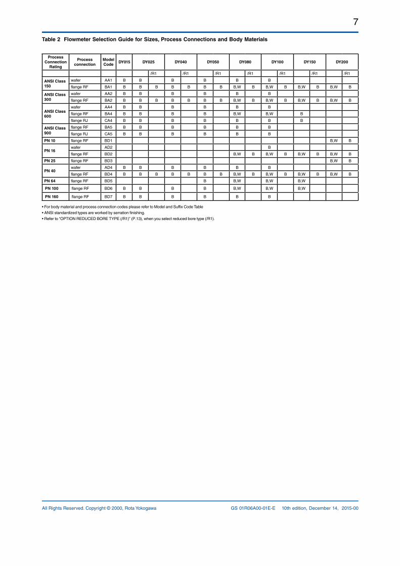
Table 2 Flowmeter Selection Guide for Sizes, Process Connections and Body Materials
Process Connection
Rating
Process connection
Model Code
DY015 DY025 DY040 DY050 DY080 DY100 DY150 DY200
/R1 /R1 /R1 /R1 /R1 /R1 /R1
ANSI Class 150
wafer AA1 B B B B B B
flange RF BA1 B B B B B B B B,W B B,W B B,W B B,W B
ANSI Class 300
wafer AA2 B B B B B B
flange RF BA2 B B B B B B B B,W B B,W B B,W B B,W B
ANSI Class 600
wafer AA4 B B B B B B
flange RF BA4 B B B B B,W B,W B
flange RJ CA4 B B B B B B B
ANSI Class 900
flange RF BA5 B B B B B B
flange RJ CA5 B B B B B B
PN 10 flange RF BD1 B,W B
PN 16wafer AD2 B
flange RF BD2 B,W B B,W B B,W B B,W B
PN 25 flange RF BD3 B,W B
PN 40wafer AD4 B B B B B B
flange RF BD4 B B B B B B B B,W B B,W B B,W B B,W B
PN 64 flange RF BD5 B B,W B,W B,W
PN 100 flange RF BD6 B B B B B,W B,W B,W
PN 160 flange RF BD7 B B B B B B
• For body material and process connection codes please refer to Model and Suffix Code Table
• ANSI standardized types are worked by serration finishing.
• Refer to “OPTION REDUCED BORE TYPE (/R1)” (P.13), when you select reduced bore type (/R1).
8
All Rights Reserved. Copyright © 2000, Rota YokogawaGS 01R06A00-01E-E 10th edition, December 14, 2015-00
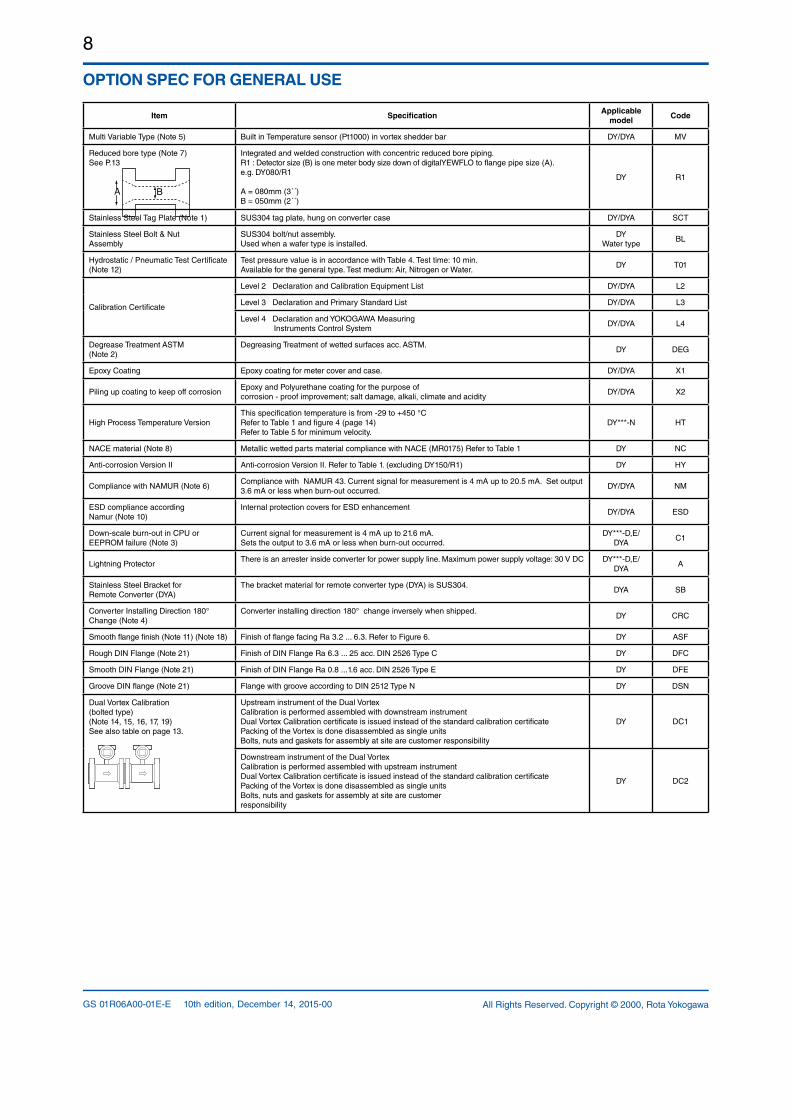
OPTION SPEC FOR GENERAL USE
Item SpecificationApplicable
modelCode
Multi Variable Type (Note 5) Built in Temperature sensor (Pt1000) in vortex shedder bar DY/DYA MV
Reduced bore type (Note 7)See P.13
Integrated and welded construction with concentric reduced bore piping.R1 : Detector size (B) is one meter body size down of digitalYEWFLO to flange pipe size (A).e.g. DY080/R1 A = 080mm (3´´)B = 050mm (2´´)
DY R1
Stainless Steel Tag Plate (Note 1) SUS304 tag plate, hung on converter case DY/DYA SCT
Stainless Steel Bolt & Nut Assembly
SUS304 bolt/nut assembly.Used when a wafer type is installed.
DY Water type
BL
Hydrostatic / Pneumatic Test Certificate(Note 12)
Test pressure value is in accordance with Table 4. Test time: 10 min.Available for the general type. Test medium: Air, Nitrogen or Water.
DY T01
Calibration Certificate
Level 2 Declaration and Calibration Equipment List DY/DYA L2
Level 3 Declaration and Primary Standard List DY/DYA L3
Level 4 Declaration and YOKOGAWA Measuring Instruments Control System
DY/DYA L4
Degrease Treatment ASTM(Note 2)
Degreasing Treatment of wetted surfaces acc. ASTM.DY DEG
Epoxy Coating Epoxy coating for meter cover and case. DY/DYA X1
Piling up coating to keep off corrosionEpoxy and Polyurethane coating for the purpose of corrosion proof improvement; salt damage, alkali, climate and acidity
DY/DYA X2
High Process Temperature VersionThis specification temperature is from 29 to +450 °CRefer to Table 1 and figure 4 (page 14)Refer to Table 5 for minimum velocity.
DY***N HT
NACE material (Note 8) Metallic wetted parts material compliance with NACE (MR0175) Refer to Table 1 DY NC
Anticorrosion Version II Anticorrosion Version II. Refer to Table 1. (excluding DY150/R1) DY HY
Compliance with NAMUR (Note 6)Compliance with NAMUR 43. Current signal for measurement is 4 mA up to 20.5 mA. Set output 3.6 mA or less when burnout occurred.
DY/DYA NM
ESD compliance according Namur (Note 10)
Internal protection covers for ESD enhancementDY/DYA ESD
Downscale burnout in CPU or EEPROM failure (Note 3)
Current signal for measurement is 4 mA up to 21.6 mA.Sets the output to 3.6 mA or less when burnout occurred.
DY***D,E/DYA
C1
Lightning ProtectorThere is an arrester inside converter for power supply line. Maximum power supply voltage: 30 V DC DY***D,E/
DYAA
Stainless Steel Bracket for Remote Converter (DYA)
The bracket material for remote converter type (DYA) is SUS304.DYA SB
Converter Installing Direction 180°Change (Note 4)
Converter installing direction 180° change inversely when shipped.DY CRC
Smooth flange finish (Note 11) (Note 18) Finish of flange facing Ra 3.2 ... 6.3. Refer to Figure 6. DY ASF
Rough DIN Flange (Note 21) Finish of DIN Flange Ra 6.3 ... 25 acc. DIN 2526 Type C DY DFC
Smooth DIN Flange (Note 21) Finish of DIN Flange Ra 0.8 ...1.6 acc. DIN 2526 Type E DY DFE
Groove DIN flange (Note 21) Flange with groove according to DIN 2512 Type N DY DSN
Dual Vortex Calibration(bolted type)(Note 14, 15, 16, 17, 19)See also table on page 13.
Upstream instrument of the Dual VortexCalibration is performed assembled with downstream instrumentDual Vortex Calibration certificate is issued instead of the standard calibration certificatePacking of the Vortex is done disassembled as single units Bolts, nuts and gaskets for assembly at site are customer responsibility
DY DC1
Downstream instrument of the Dual VortexCalibration is performed assembled with upstream instrumentDual Vortex Calibration certificate is issued instead of the standard calibration certificatePacking of the Vortex is done disassembled as single units Bolts, nuts and gaskets for assembly at site are customer responsibility
DY DC2
BA

9
All Rights Reserved. Copyright © 2000, Rota Yokogawa GS 01R06A00-01E-E 10th edition, December 14, 2015-00
OPTION SPEC FOR GENERAL USE continued
Item SpecificationApplicable
modelCode
Material certificates: Mill sheets(Note 13)
Each certificate to be attached produced by the vendors.
DY
Item to be specified
1. Meterbody M01
1. Meterbody, 2. Shedder bar M02
1. Meterbody, 2. Shedder bar, 3. Bottom plug
M03
1. Meterbody, 2. Shedder bar, 3. Bottom plug, 4. Welding rod
M04
Material certificates: 3.1
3.1 certificate which is attached according to EN10204.Each certificate which is attached produced by the vendors
DY
Item to be specified
1. Meterbody E01
1. Meterbody, 2. Shedder bar E02
1. Meterbody, 2. Shedder bar, 3. Bottom plug
E03
1. Meterbody, 2. Shedder bar, 3. Bottom plug, 4. Welding rod
E04
PAMI test certificate
Positive Material Identification certificate to be attached for the main 3 chemical components of specified materials. Each certificate to be attached.
DYItem to be specified
1. Meterbody PM1
1. Meterbody, 2. Shedder bar PM2
DIN EN weldingdocuments submission
1. Welder/Welding Operator Performance Qualification (or Welder Qualification Record)2. Welding Procedure Specification (WPS)3. Procedure Qualification Record (PQR)Each certificate to be attached. The customer’s name and job name to be specified when ordered.
DY WP
Item to be specified
1. Welded portion for the bottom plug 2. Welded portion for the flange in case of the welding construction
Dye Penetrant test certificateItem to be specified
Welded portion for the bottom plugDY PT
Final product certificate (Note 9)
Final Product Certificates (FPC) acc. to EN 10204:2004 Certificate of marking transfer material Certificates acc. DIN EN 10204:2004 – 3.1 for all materials of body, shedder bar, plug and plate and welding rod. Test Report acc. to DIN EN 10204:2004 2.2 WQC, WPS, PQR for plug welding Inspection Report to DyePenetrationTest for plug welding (e.g. /PT)
DY FPC
(Note 1) When /SCT is not chosen, the specified Tag Number is engraved on the data plate. When /SCT is chosen, the specified Tag Number is engraved on the data plate and stainless tag plate. The limitation of characters for Tag Number on name plate and stainless steel tag plate: 16 characters (see page 34).(Note 2) Due to the DY design small amounts of the alkaline cleaning solution could remain in the flow tube.(Note 3) The output is set to 3.6mA or less (General type is set to 21.6mA or more at shipping).(Note 4) When /CRC is chosen, the electrical connection is turned to a downstream side.(Note 5) Refer to “OPTION SPEC. FOR MULTIVARIABLE TYPE (/MV)” (p.12). In case of Remote type detector (DY***N), select “/MV” both DY and DYA.(Note 6) /NM can not be combined with Remote type detector (DY***N).(Note 7) • High process temperature version (/HT) and Multi-variable type (/MV) for DY025/R1 is not available. • Flange type only and available process connections are ANSI150, 300 (BA1,BA2), DIN PN 10 - DIN PN40 (BD1 - BD4), see table 2. • Flange piping size (A) means “DY***-” nominal size.(Note 8) Applicability and limitations for the usage of wetted part materials are according to NACEMR0175(Note 9) Accumulation of options /E04, /WP, /PT(Note 10) Option /ESD is not possible / not necessary for units without display or with Foundation Fieldbus Communication.(Note 11) Only available for DY015 to DY100 with AA1, AA2, AA4 and DY015 to DY200 with BA1, BA2, BA4, BA5.(Note 12) In the Test report is the confirmation (”OK”) about the pressure test which was done with positive result.(Note 13) Certificates may be substituted by Material Certificates acc. EN 102043.1, depending on material supplier.(Note 14) Not available: DY with wafer, DY with option /R1 and DY150 CA4(Note 15) For Dual Vortex in bidirectional use please contact your Yokogawa sales office.(Note 16) Pressure test is performed separately for upstream and for downstream unit.(Note 17) Applicable maximum flow velocity (liquid) is 5,5 m/s with specified accuracy. Proven by standard calibration certificate (media water). Higher flow velocities may result in lower accuracy.(Note 18) Option /ASF not available for the following process connections: BA4 with /R*, CA4 with /R*(Note 19 For use with reducer types please contact your Yokogawa Sales Office.(Note 21) Only valid for flanges BD1 to BD7
10
All Rights Reserved. Copyright © 2000, Rota YokogawaGS 01R06A00-01E-E 10th edition, December 14, 2015-00
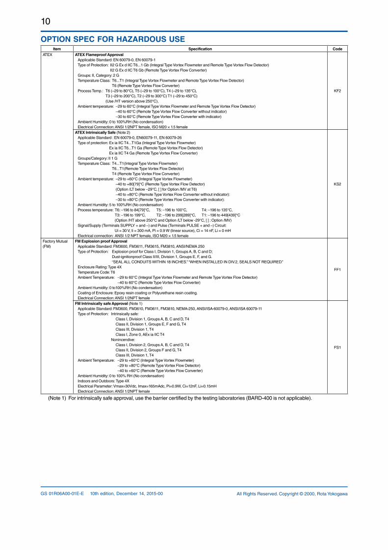
OPTION SPEC FOR HAZARDOUS USEItem Specification Code
ATEX ATEX Flameproof ApprovalApplicable Standard: EN 600790, EN 600791Type of Protection: II2 G Ex d IIC T6...1 Gb (Integral Type Vortex Flowmeter and Remote Type Vortex Flow Detector)
II2 G Ex d IIC T6 Gb (Remote Type Vortex Flow Converter)Groups: II, Category: 2 GTemperature Class: T6...T1 (Integral Type Vortex Flowmeter and Remote Type Vortex Flow Detector) T6 (Remote Type Vortex Flow Converter)Process Temp.: T6 (–29 to 80°C), T5 (–29 to 100°C), T4 (–29 to 135°C), T3 (–29 to 200°C), T2 (–29 to 300°C) T1 (–29 to 450°C) (Use /HT version above 250°C),Ambient temperature: –29 to 60°C (Integral Type Vortex Flowmeter and Remote Type Vortex Flow Detector)
–40 to 60°C (Remote Type Vortex Flow Converter without indicator)–30 to 60°C (Remote Type Vortex Flow Converter with indicator)
Ambient Humidity: 0 to 100%RH (No condensation)Electrical Connection: ANSI 1/2NPT female, ISO M20 × 1.5 female
KF2
ATEX Intrinsically Safe (Note 2)Applicable Standard : EN 600790, EN6007911, EN 6007926Type of protection: Ex ia IIC T4...T1Ga (Integral Type Vortex Flowmeter)
Ex ia IIC T6...T1 Ga (Remote Type Vortex Flow Detector)Ex ia IIC T4 Ga (Remote Type Vortex Flow Converter)
Groups/Category: II 1 GTemperature Class: T4...T1(Integral Type Vortex Flowmeter)
T6...T1(Remote Type Vortex Flow Detector)T4 (Remote Type Vortex Flow Converter)
Ambient temperature: –29 to +60°C (Integral Type Vortex Flowmeter) –40 to +80[79]°C (Remote Type Vortex Flow Detector)
(Option /LT below –29°C, [ ] for Option /MV at T6)–40 to +80°C (Remote Type Vortex Flow Converter without indicator): –30 to +80°C (Remote Type Vortex Flow Converter with indicator):
Ambient Humidity: 5 to 100%RH (No condensation)Process temperature: T6: –196 to 84[79]°C, T5: –196 to 100°C, T4: –196 to 135°C,
T3: –196 to 199°C, T2: –196 to 299[289]°C, T1: –196 to 449[439]°C(Option /HT above 250°C and Option /LT below 29°C, [ ] : Option /MV)
Signal/Supply (Terminals SUPPLY + and –) and Pulse (Terminals PULSE + and –) Circuit: Ui = 30 V, Ii = 300 mA, Pi = 0.9 W (linear source), Ci = 14 nF, Li = 0 mHElectrical connection: ANSI 1/2 NPT female, ISO M20 × 1.5 female
KS2
Factory Mutual(FM)
FM Explosion proof ApprovalApplicable Standard: FM3600, FM3611, FM3615, FM3810, ANSI/NEMA 250Type of Protection: Explosion proof for Class I, Division 1, Groups A, B, C and D; Dustignitionproof Class II/III, Division 1, Groups E, F, and G. “SEAL ALL CONDUITS WITHIN 18 INCHES.” “WHEN INSTALLED IN DIV.2, SEALS NOT REQUIRED.”Enclosure Rating: Type 4XTemperature Code: T6Ambient Temperature: –29 to 60°C (Integral Type Vortex Flowmeter and Remote Type Vortex Flow Detector) –40 to 60°C (Remote Type Vortex Flow Converter)Ambient Humidity: 0 to100%RH (No condensation)Coating of Enclosure: Epoxy resin coating or Polyurethane resin coating.Electrical Connection: ANSI 1/2NPT female
FF1
FM Intrinsically safe Approval (Note 1)Applicable Standard: FM3600, FM3610, FM3611, FM3810, NEMA250, ANSI/ISA600790, ANSI/ISA 6007911Type of Protection: Intrinsically safe: Class I, Division 1, Groups A, B, C and D, T4 Class II, Division 1, Groups E, F and G, T4 Class III, Division 1, T4 Class I, Zone 0, AEx ia IIC T4 Nonincendive: Class I, Division 2, Groups A, B, C and D, T4 Class II, Division 2, Groups F and G, T4 Class III, Division 1, T4Ambient Temperature: –29 to +60°C (Integral Type Vortex Flowmeter) –29 to +80°C (Remote Type Vortex Flow Detector) –40 to +60°C (Remote Type Vortex Flow Converter)Ambient Humidity: 0 to 100% RH (No condensation)Indoors and Outdoors: Type 4XElectrical Parameter: Vmax=30Vdc, Imax=165mAdc, Pi=0.9W, Ci=12nF, Li=0.15mHElectrical Connection: ANSI 1/2NPT female
FS1
(Note 1) For intrinsically safe approval, use the barrier certified by the testing laboratories (BARD400 is not applicable).
11
All Rights Reserved. Copyright © 2000, Rota Yokogawa GS 01R06A00-01E-E 10th edition, December 14, 2015-00
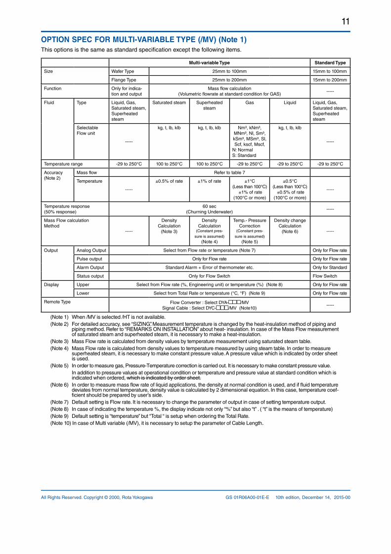
OPTION SPEC FOR MULTI-VARIABLE TYPE (/MV) (Note 1)This options is the same as standard specification except the following items.
Multi-variable Type Standard Type
Size Wafer Type 25mm to 100mm 15mm to 100mm
Flange Type 25mm to 200mm 15mm to 200mm
Function Only for indication and output
Mass flow calculation(Volumetric flowrate at standard condition for GAS)
Fluid Type Liquid, Gas,Saturated steam, Superheated steam
Saturated steam Superheated steam
Gas Liquid Liquid, Gas,Saturated steam, Superheated steam
Selectable Flow unit
kg, t, lb, klb kg, t, lb, klb Nm³, kNm³, MNm³, Nl, Sm³, kSm³, MSm³, Sl, Scf, kscf, Mscf,
N: NormalS: Standard
kg, t, lb, klb
Temperature range 29 to 250°C 100 to 250°C 100 to 250°C 29 to 250°C 29 to 250°C 29 to 250°C
Accuracy(Note 2)
Mass flow Refer to table 7
Temperature
±0.5% of rate ±1% of rate ±1°C(Less than 100°C)
±1% of rate(100°C or more)
±0.5°C(Less than 100°C)
±0.5% of rate(100°C or more)
Temperature response(50% response)
60 sec(Churning Underwater)
Mass Flow calculationMethod
Density Calculation
(Note 3)
Density Calculation
(Constant pressure is assumed)
(Note 4)
Temp. Pressure Correction
(Constant pressure is assumed)
(Note 5)
Density change Calculation
(Note 6)
Output Analog Output Select from Flow rate or temperature (Note 7) Only for Flow rate
Pulse output Only for Flow rate Only for Flow rate
Alarm Output Standard Alarm + Error of thermometer etc. Only for Standard
Status output Only for Flow Switch Flow Switch
Display Upper Select from Flow rate (%, Engineering unit) or temperature (%) (Note 8) Only for Flow rate
Lower Select from Total Rate or temperature (°C, °F) (Note 9) Only for Flow rate
Remote Type Flow Converter : Select DYA /MVSignal Cable : Select DYC /MV (Note10)
(Note 1) When /MV is selected /HT is not available.(Note 2) For detailed accuracy, see “SIZING”. Measurement temperature is changed by the heatinsulation method of piping and
piping method. Refer to “REMARKS ON INSTALLATION” about heat insulation. In case of the Mass Flow measurement of saturated steam and superheated steam, it is necessary to make a heatinsulation.
(Note 3) Mass Flow rate is calculated from density values by temperature measurement using saturated steam table.(Note 4) Mass Flow rate is calculated from density values to temperature measured by using steam table. In order to measure
superheated steam, it is necessary to make constant pressure value. A pressure value which is indicated by order sheet is used.
(Note 5) In order to measure gas, PressureTemperature correction is carried out. It is necessary to make constant pressure value. In addition to pressure values at operational condition or temperature and pressure value at standard condition which is
indicated when ordered, which is indicated by order sheet.(Note 6) In order to measure mass flow rate of liquid applications, the density at normal condition is used, and if fluid temperature
deviates from normal temperature, density value is calculated by 2 dimensional equation. In this case, temperature coefficient should be prepared by user’s side.
(Note 7) Default setting is Flow rate. It is necessary to change the parameter of output in case of setting temperature output.(Note 8) In case of indicating the temperature %, the display indicate not only “%” but also “t” . ( “t” is the means of temperature)(Note 9) Default setting is “temperature” but “Total “ is setup when ordering the Total Rate.(Note 10) In case of Multi variable (/MV), it is necessary to setup the parameter of Cable Length.
12
All Rights Reserved. Copyright © 2000, Rota YokogawaGS 01R06A00-01E-E 10th edition, December 14, 2015-00
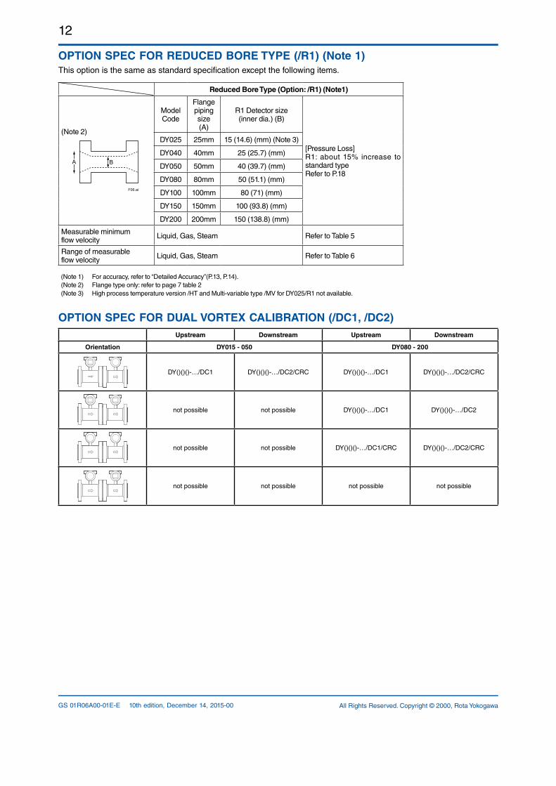
OPTION SPEC FOR REDUCED BORE TYPE (/R1) (Note 1)This option is the same as standard specification except the following items.
Reduced Bore Type (Option: /R1) (Note1)
(Note 2)
BA
F06.ai
Model Code
Flange piping size(A)
R1 Detector size(inner dia.) (B)
[Pressure Loss]R1: about 15% increase to standard typeRefer to P.18
DY025 25mm 15 (14.6) (mm) (Note 3)
DY040 40mm 25 (25.7) (mm)
DY050 50mm 40 (39.7) (mm)
DY080 80mm 50 (51.1) (mm)
DY100 100mm 80 (71) (mm)
DY150 150mm 100 (93.8) (mm)
DY200 200mm 150 (138.8) (mm)
Measurable minimumflow velocity Liquid, Gas, Steam Refer to Table 5
Range of measurableflow velocity Liquid, Gas, Steam Refer to Table 6
(Note 1) For accuracy, refer to “Detailed Accuracy”(P.13, P.14).(Note 2) Flange type only: refer to page 7 table 2 (Note 3) High process temperature version /HT and Multivariable type /MV for DY025/R1 not available.
OPTION SPEC FOR DUAL VORTEX CALIBRATION (/DC1, /DC2) Upstream Downstream Upstream Downstream
Orientation DY015 - 050 DY080 - 200
DY()()()…/DC1 DY()()()…/DC2/CRC DY()()()…/DC1 DY()()()…/DC2/CRC
not possible not possible DY()()()…/DC1 DY()()()…/DC2
not possible not possible DY()()()…/DC1/CRC DY()()()…/DC2/CRC
not possible not possible not possible not possible
13
All Rights Reserved. Copyright © 2000, Rota Yokogawa GS 01R06A00-01E-E 10th edition, December 14, 2015-00
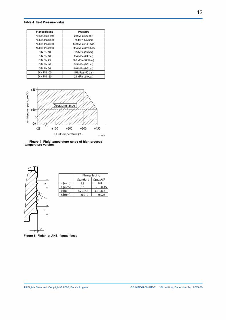
Table 4 Test Pressure Value
Flange Rating Pressure
ANSI Class 150 2.9 MPa (29 bar)
ANSI Class 300 7.5 MPa (75 bar)
ANSI Class 600 14.9 MPa (149 bar)
ANSI Class 900 22.4 MPa (223 bar)
DIN PN 10 1.5 MPa (15 bar)
DIN PN 16 2.4 MPa (24 bar)
DIN PN 25 3.8 MPa (37.5 bar)
DIN PN 40 5.9 MPa (60 bar)
DIN PN 64 9.6 MPa (96 bar)
DIN PN 100 15 MPa (150 bar)
DIN PN 160 24 MPa (240bar)
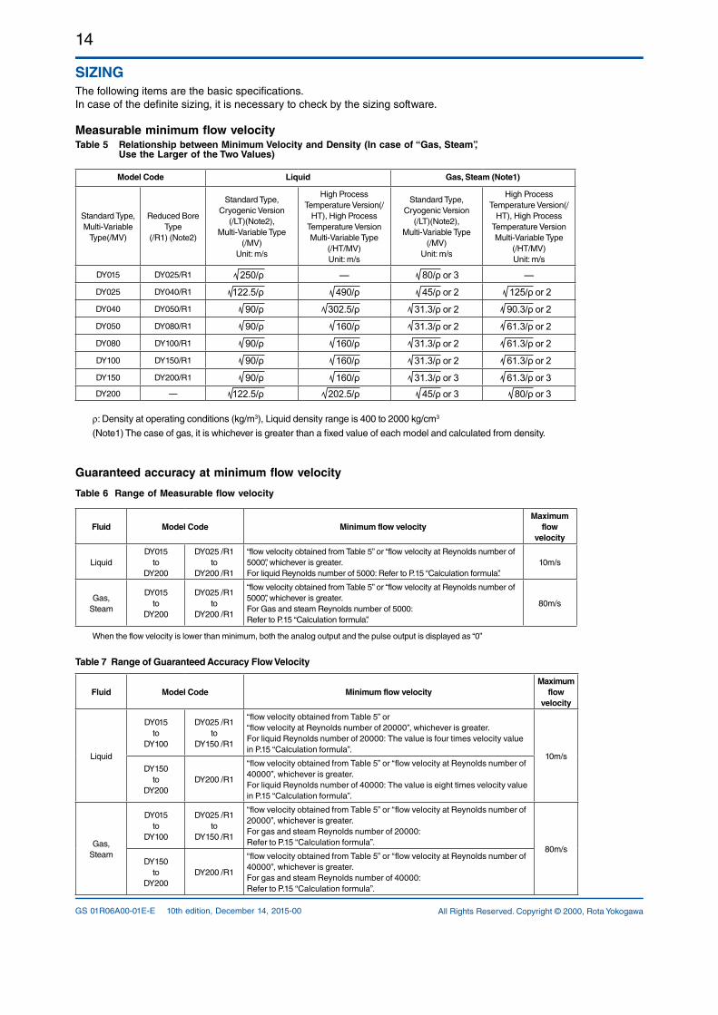
-29 +100 +200 +300 +450
+85
+60
-29
Fluid temperature (˚C)
Am
bie
nt t
emp
erat
ure
(˚C
)
Operating range
DYF Fig-04
Figure 4 Fluid temperature range of high process temperature version
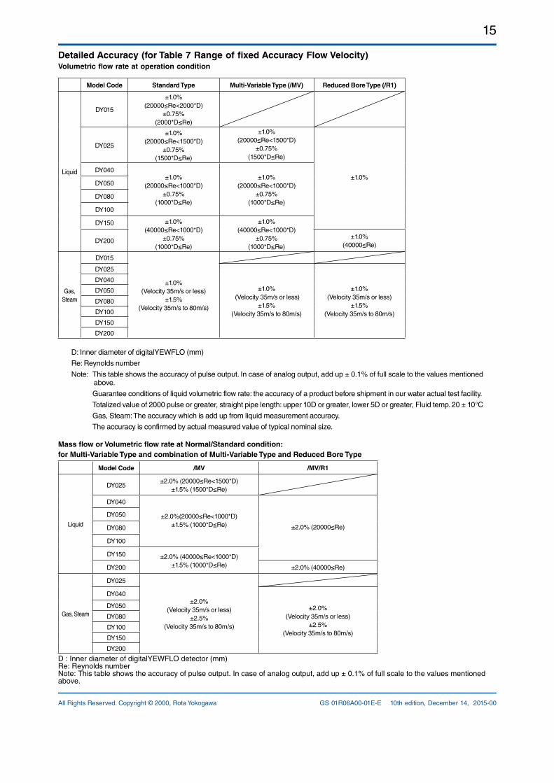
Figure 5 Finish of ANSI flange faces
c
ab
1
rc [mm]b [Ra]a [mm/U]r [mm]
Standard Opt. /ASF
Flange facing
1.80.5
3.2 ... 6.30.017
0.80.35 ... 0.45
3.2 ... 6.30.025
14
All Rights Reserved. Copyright © 2000, Rota YokogawaGS 01R06A00-01E-E 10th edition, December 14, 2015-00
SIZINGThe following items are the basic specifications. In case of the definite sizing, it is necessary to check by the sizing software.
Measurable minimum flow velocityTable 5 Relationship between Minimum Velocity and Density (In case of “Gas, Steam”, Use the Larger of the Two Values)
Model Code Liquid Gas, Steam (Note1)
Standard Type, MultiVariable
Type(/MV)
Reduced Bore Type
(/R1) (Note2)
Standard Type, Cryogenic Version
(/LT)(Note2), MultiVariable Type
(/MV)Unit: m/s
High Process Temperature Version(/
HT), High Process Temperature Version MultiVariable Type
(/HT/MV)Unit: m/s
Standard Type, Cryogenic Version
(/LT)(Note2), MultiVariable Type
(/MV)Unit: m/s
High Process Temperature Version(/
HT), High Process Temperature Version MultiVariable Type
(/HT/MV)Unit: m/s
DY015 DY025/R1 250/ρ — 80/ρ or 3 —
DY025 DY040/R1 122.5/ρ 490/ρ 45/ρ or 2 125/ρ or 2
DY040 DY050/R1 90/ρ 302.5/ρ 31.3/ρ or 2 90.3/ρ or 2
DY050 DY080/R1 90/ρ 160/ρ 31.3/ρ or 2 61.3/ρ or 2
DY080 DY100/R1 90/ρ 160/ρ 31.3/ρ or 2 61.3/ρ or 2
DY100 DY150/R1 90/ρ 160/ρ 31.3/ρ or 2 61.3/ρ or 2
DY150 DY200/R1 90/ρ 160/ρ 31.3/ρ or 3 61.3/ρ or 3DY200 — 122.5/ρ 202.5/ρ 45/ρ or 3 80/ρ or 3
r: Density at operating conditions (kg/m3), Liquid density range is 400 to 2000 kg/cm3
(Note1) The case of gas, it is whichever is greater than a fixed value of each model and calculated from density.
Guaranteed accuracy at minimum flow velocity
Table 6 Range of Measurable flow velocity
Fluid Model Code Minimum flow velocityMaximum
flowvelocity
LiquidDY015
toDY200
DY025 /R1 to
DY200 /R1
“flow velocity obtained from Table 5” or “flow velocity at Reynolds number of 5000”, whichever is greater. For liquid Reynolds number of 5000: Refer to P.15 “Calculation formula”.
10m/s
Gas,Steam
DY015to
DY200
DY025 /R1 to
DY200 /R1
“flow velocity obtained from Table 5” or “flow velocity at Reynolds number of 5000”, whichever is greater.For Gas and steam Reynolds number of 5000:Refer to P.15 “Calculation formula”.
80m/s
When the flow velocity is lower than minimum, both the analog output and the pulse output is displayed as “0”
Table 7 Range of Guaranteed Accuracy Flow Velocity
Fluid Model Code Minimum flow velocityMaximum
flowvelocity
Liquid
DY015to
DY100
DY025 /R1 to
DY150 /R1
“flow velocity obtained from Table 5” or“flow velocity at Reynolds number of 20000”, whichever is greater.For liquid Reynolds number of 20000: The value is four times velocity value in P.15 “Calculation formula”.
10m/s
DY150to
DY200DY200 /R1
“flow velocity obtained from Table 5” or “flow velocity at Reynolds number of 40000”, whichever is greater.For liquid Reynolds number of 40000: The value is eight times velocity value in P.15 “Calculation formula”.
Gas,Steam
DY015to
DY100
DY025 /R1 to
DY150 /R1
“flow velocity obtained from Table 5” or “flow velocity at Reynolds number of 20000”, whichever is greater.For gas and steam Reynolds number of 20000:Refer to P.15 “Calculation formula”.
80m/s
DY150to
DY200DY200 /R1
“flow velocity obtained from Table 5” or “flow velocity at Reynolds number of 40000”, whichever is greater. For gas and steam Reynolds number of 40000:Refer to P.15 “Calculation formula”.
15
All Rights Reserved. Copyright © 2000, Rota Yokogawa GS 01R06A00-01E-E 10th edition, December 14, 2015-00
Detailed Accuracy (for Table 7 Range of fixed Accuracy Flow Velocity)Volumetric flow rate at operation condition
Model Code Standard Type Multi-Variable Type (/MV) Reduced Bore Type (/R1)
Liquid
DY015
±1.0% (20000≤Re<2000*D)
±0.75% (2000*D≤Re)
DY025
±1.0% (20000≤Re<1500*D)
±0.75% (1500*D≤Re)
±1.0% (20000≤Re<1500*D)
±0.75% (1500*D≤Re)
±1.0%DY040
±1.0% (20000≤Re<1000*D)
±0.75% (1000*D≤Re)
±1.0% (20000≤Re<1000*D)
±0.75% (1000*D≤Re)
DY050
DY080
DY100
DY150 ±1.0% (40000≤Re<1000*D)
±0.75% (1000*D≤Re)
±1.0% (40000≤Re<1000*D)
±0.75% (1000*D≤Re)
DY200±1.0%
(40000≤Re)
Gas, Steam
DY015
±1.0% (Velocity 35m/s or less)
±1.5% (Velocity 35m/s to 80m/s)
DY025
±1.0% (Velocity 35m/s or less)
±1.5% (Velocity 35m/s to 80m/s)
±1.0% (Velocity 35m/s or less)
±1.5% (Velocity 35m/s to 80m/s)
DY040
DY050
DY080
DY100
DY150
DY200
D: Inner diameter of digitalYEWFLO (mm)
Re: Reynolds number
Note: This table shows the accuracy of pulse output. In case of analog output, add up ± 0.1% of full scale to the values mentioned above.
Guarantee conditions of liquid volumetric flow rate: the accuracy of a product before shipment in our water actual test facility.
Totalized value of 2000 pulse or greater, straight pipe length: upper 10D or greater, lower 5D or greater, Fluid temp. 20 ± 10°C
Gas, Steam: The accuracy which is add up from liquid measurement accuracy.
The accuracy is confirmed by actual measured value of typical nominal size.
Mass flow or Volumetric flow rate at Normal/Standard condition:for Multi-Variable Type and combination of Multi-Variable Type and Reduced Bore Type
Model Code /MV /MV/R1
Liquid
DY025±2.0% (20000≤Re<1500*D)
±1.5% (1500*D≤Re)
DY040
±2.0%(20000≤Re<1000*D)±1.5% (1000*D≤Re) ±2.0% (20000≤Re)
DY050
DY080
DY100
DY150 ±2.0% (40000≤Re<1000*D)±1.5% (1000*D≤Re)DY200 ±2.0% (40000≤Re)
Gas, Steam
DY025
±2.0%(Velocity 35m/s or less)
±2.5%(Velocity 35m/s to 80m/s)
DY040
±2.0%(Velocity 35m/s or less)
±2.5%(Velocity 35m/s to 80m/s)
DY050
DY080
DY100
DY150
DY200
D : Inner diameter of digitalYEWFLO detector (mm) Re: Reynolds number Note: This table shows the accuracy of pulse output. In case of analog output, add up ± 0.1% of full scale to the values mentioned above.
16
All Rights Reserved. Copyright © 2000, Rota YokogawaGS 01R06A00-01E-E 10th edition, December 14, 2015-00
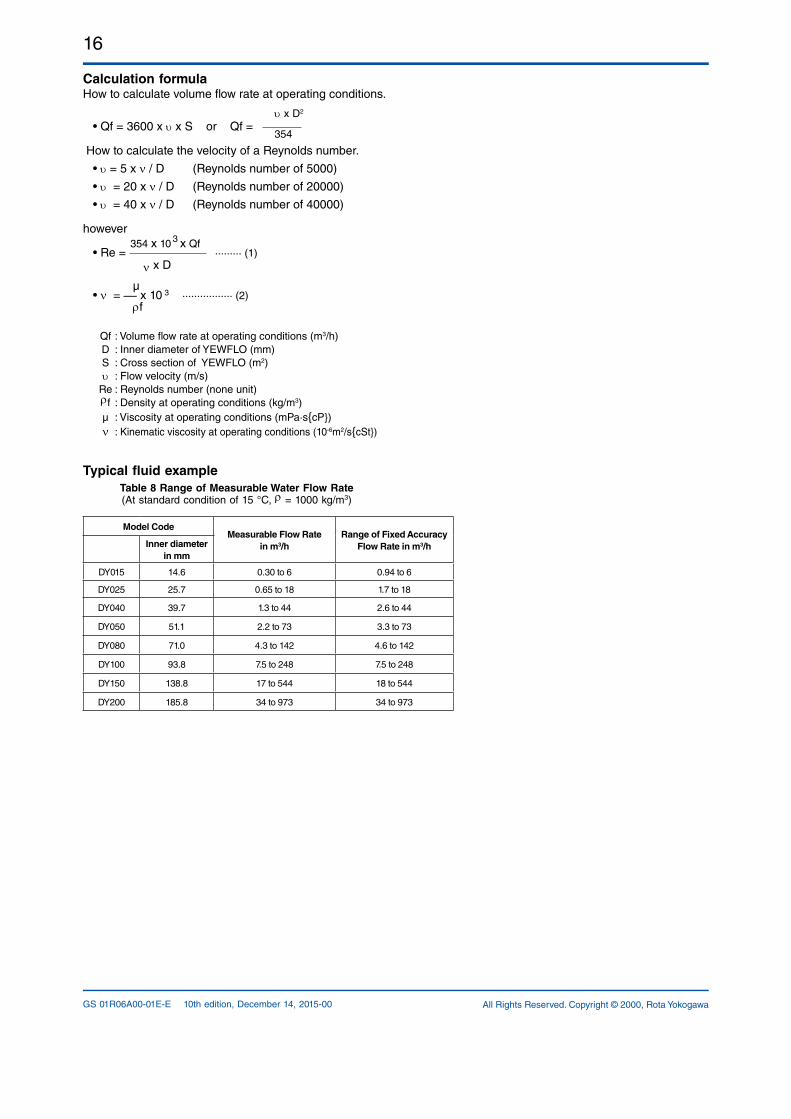
Calculation formulaHow to calculate volume flow rate at operating conditions.
υ x D2 • Qf = 3600 x υ x S or Qf = 354
How to calculate the velocity of a Reynolds number.
• υ = 5 x ν / D (Reynolds number of 5000)
• υ = 20 x ν / D (Reynolds number of 20000)
• υ = 40 x ν / D (Reynolds number of 40000)
however 354 x 10
3 x Qf
• Re = ········· (1) ν x D
µ • ν = __ x 10 3 ················· (2) ρf
Qf : Volume flow rate at operating conditions (m3/h) D : Inner diameter of YEWFLO (mm) S : Cross section of YEWFLO (m2) υ : Flow velocity (m/s) Re : Reynolds number (none unit) ρf : Density at operating conditions (kg/m3) µ : Viscosity at operating conditions (mPa·scP) ν : Kinematic viscosity at operating conditions (106m2/scSt)
Typical fluid example Table 8 Range of Measurable Water Flow Rate(At standard condition of 15 °C, ρ = 1000 kg/m3)
Model Code Measurable Flow Rate
in m3/h Range of Fixed Accuracy
Flow Rate in m3/h Inner diameter in mm
DY015 14.6 0.30 to 6 0.94 to 6
DY025 25.7 0.65 to 18 1.7 to 18
DY040 39.7 1.3 to 44 2.6 to 44
DY050 51.1 2.2 to 73 3.3 to 73
DY080 71.0 4.3 to 142 4.6 to 142
DY100 93.8 7.5 to 248 7.5 to 248
DY150 138.8 17 to 544 18 to 544
DY200 185.8 34 to 973 34 to 973
17
All Rights Reserved. Copyright © 2000, Rota Yokogawa GS 01R06A00-01E-E 10th edition, December 14, 2015-00
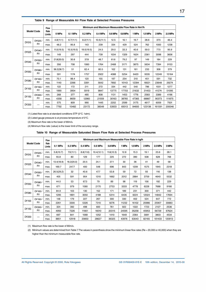
Table 9 Range of Measurable Air Flow Rate at Selected Process Pressures
Model CodeFlow Rate
Limits
Minimum and Maximum Measurable Flow Rate in Nm3/h
0 MPa 0.1 MPa 0.2 MPa 0.4 MPa 0.6 MPa 0.8 MPa 1 MPa 1.5 MPa 2 MPa 2.5 MPa
DY015 DY025 /
R1
min. 4.8(11.1) 6.7(11.1) 8.2(11.1) 10.5(11.1) 12.5 16.1 19.7 28.6 37.5 46.4
max. 48.2 95.8 143 239 334 429 524 762 1000 1238
DY025 DY040 /
R1
min. 11.0(19.5) 15.5(19.5) 19.0(19.5) 24.5 29.0 33.3 40.6 59.0 77.5 95.9
max. 149 297 444 739 1034 1329 1624 2361 3098 3836
DY040 DY050 /
R1
min. 21.8(30.0) 30.8 37.8 48.7 61.6 79.2 97 149 184 229
max. 356 708 1060 1764 2468 3171 3875 5634 7394 9153
DY050 DY080 /
R1
min. 36.2(38.7) 51 62.4 80.5 102 131 161 233 306 379
max. 591 1174 1757 2922 4088 5254 6420 9335 12249 15164
DY080 DY100 /
R1
min. 70.1 98.4 120 155 197 254 310 451 591 732
max. 1140 2266 3391 5642 7892 10143 12394 18021 23648 29274
DY100 DY150 /
R1
min. 122 172 211 272 334 442 540 786 1031 1277
max. 1990 3954 5919 9847 13775 17703 21632 31453 41274 51095
DY150 DY200 /
R1
min. 268 377 485 808 1131 1453 1776 2583 3389 4196
max. 4358 8659 12960 21559 30163 38765 47365 68867 90373 111875
DY200 — min. 575 809 990 1445 2202 2599 3175 4617 6059 7501
max. 7792 15482 23172 38549 53933 69313 84693 123138 161591 200046
(1) Listed flow rate is at standard conditions STP (0°C. 1atm).
(2) Listed gauge pressure is at process temperature of 0°C.
(3) Maximum flow rate is the lower of 80m/s.
(4) Minimum flow rate: (value) is the lower limit of the accuracy range.
Table 10 Range of Measurable Saturated Steam Flow Rate at Selected Process Pressures
Model CodeFlow Rate
Limits
Minimum and Maximum Measurable Flow Rate in kg/h
0.1 MPa 0.2 MPa 0.4 MPa 0.6 MPa 0.8 MPa 1 MPa 1.5 MPa 2 MPa 2.5 MPa 3 MPa
DY015 DY025 /
R1
min. 5.8(10.7) 7.0(11.1) 8.8(11.6) 10.4(12.1) 11.6(12.3) 12.8 15.3 19.1 23.6 28.1
max. 55.8 80 129 177 225 272 390 508 628 748
DY025 DY040 /
R1
min. 13.4(18.9) 16.2(20.0) 20.5 24.1 27.1 30 36 41 49 58
max. 169.7 247.7 400 548 696 843 1209 1575 1945 2318
DY040 DY050 /
R1
min. 26.5(29.2) 32 40.6 47.7 53.8 59 72 93 116 138
max. 405 591 954 1310 1662 2012 2884 3759 4640 5532
DY050 DY080 /
R1
min. 44.0 53 67.3 79 89 98 119 156 192 229
max. 671 979 1580 2170 2753 3333 4778 6228 7688 9166
DY080 DY100 /
R1
min. 84.9 103 130 152 171 189 231 300 371 442
max. 1295 1891 3050 4188 5314 6435 9224 12024 14842 17694
DY100 DY150 /
R1
min. 148 179 227 267 300 330 402 524 647 772
max. 2261 3300 5326 7310 9276 11232 16102 20986 25907 30883
DY150 DY200 /
R1
min. 324 392 498 600 761 922 1322 1723 2127 2536
max. 4950 7226 11661 16010 20315 24595 35258 45953 56729 67624
DY200 — min. 697 841 1068 1252 1410 1649 2364 3081 3803 4534
max. 8851 12918 20850 28627 36325 43976 63043 82165 101433 120913
(1) Maximum flow rate is the lower of 80m/s.
(2) Minimum values are determined from Table 7. The values in parenthesis show the minimum linear flow rates (Re = 20,000 or 40,000) when they are
higher than the minimum measurable flow rate.
18
All Rights Reserved. Copyright © 2000, Rota YokogawaGS 01R06A00-01E-E 10th edition, December 14, 2015-00
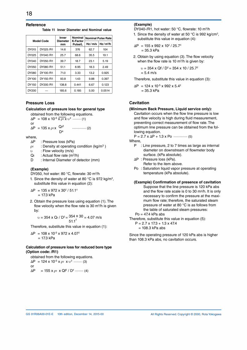
Reference Table 11 Inner Diameter and Nominal value
Model CodeInner
Diameter mm
Nominal K-Factor Pulse/L
Nominal Pulse Rate
Hz / m/s Hz / m3/h
DY015 DY025 /R1 14.6 376 62.7 104
DY025 DY040 /R1 25.7 68.6 35.5 19.1
DY040 DY050 /R1 39.7 18.7 23.1 5.19
DY050 DY080 /R1 51.1 8.95 18.3 2.49
DY080 DY100 /R1 71.0 3.33 13.2 0.925
DY100 DY150 /R1 93.8 1.43 9.88 0.397
DY150 DY200 /R1 138.8 0.441 6.67 0.123
DY200 — 185.6 0.185 5.00 0.0514
Pressure LossCalculation of pressure loss for general type
obtained from the following equations.∆P = 108 x 105 x ρf x υ2 ········· (1)or∆P = 135 x ρf x Qf2
··············· (2)
D4
where,∆P : Pressure loss (kPa)ρf : Density at operating condition (kg/m3 )υ : Flow velocity (m/s)Qf : Actual flow rate (m3/h)D : Internal Diameter of detector (mm)
(Example) DY050, hot water: 80 °C, flowrate: 30 m3/h1. Since the density of water at 80 °C is 972 kg/m3,
substitute this value in equation (2):
∆P = 135 x 972 x 302 / 51.14
= 17.3 kPa
2. Obtain the pressure loss using equation (1). The flow velocity when the flow rate is 30 m3/h is given by:
υ = 354 x Qf / D2 = 354 x 30 = 4.07 m/s 51.1
2
Therefore, substitute this value in equation (1):
∆P = 108 x 105 x 972 x 4.072
= 17.3 kPa
Calculation of pressure loss for reduced bore type(Option code: /R1)
obtained from the following equations.∆P = 124 x 105 x ρf x υ2 ········· (3)or∆P = 155 x ρf x Qf2 / D4 ········ (4)
(Example) DY040/R1, hot water: 50 °C, flowrate: 10 m3/h1. Since the density of water at 50 °C is 992 kg/cm3,
substitute this value in equation (4):
∆P = 155 x 992 x 102 / 25.74
= 35.3 kPa
2. Obtain by using equation (3). The flow velocity when the flow rate is 10 m3/h is given by:
υ = 354 x Qf / D2 = 354 x 10 / 25.72
= 5.4 m/s
Therefore, substitute this value in equation (3):
∆P = 124 x 105 x 992 x 5.42
= 35.3 kPa
Cavitation(Minimum Back Pressure, Liquid service only):
Cavitation occurs when the flow line pressure is low and flow velocity is high during fluid measurement, preventing correct measurement of flow rate. The optimum line pressure can be obtained from the following equation.P = 2.7 x ∆P + 1.3 x Po
··············· (5)
Where,P : Line pressure, 2 to 7 times as large as internal
diameter on downstream of flowmeter body surface. (kPa absolute).
∆P : Pressure loss (kPa). Refer to the item above.Po : Saturation liquid vapor pressure at operating
temperature (kPa absolute).
(Example) Confirmation of presence of cavitation Suppose that the line pressure is 120 kPa abs and the flow rate scale is 0 to 30 m3/h. It is only necessary to confirm the pressure at the maximum flow rate; therefore, the saturated steam pressure of water at 80 °C is as follows from the table of saturated steam pressures:
Po = 47.4 kPa abs Therefore, substitute this value in equation (5): P = 2.7 x 17.3 + 1.3 x 47.4 = 108.3 kPa abs
Since the operating pressure of 120 kPa abs is higher than 108.3 kPa abs, no cavitation occurs.
19
All Rights Reserved. Copyright © 2000, Rota Yokogawa GS 01R06A00-01E-E 10th edition, December 14, 2015-00
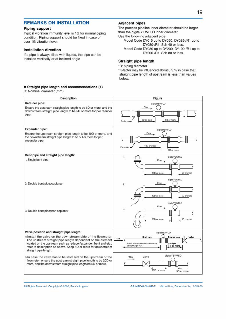
Adjacent pipesThe process pipeline inner diameter should be larger than the digitalYEWFLO inner diameter.Use the following adjacent pipe. Model Code DY015 up to DY050, DY025/R1 up to DY080/R1: Sch 40 or less. Model Code DY080 up to DY200, DY100/R1 up to DY200/R1: Sch 80 or less. Straight pipe length*D: piping diameter*Kfactor may be influenced about 0.5 % in case that straight pipe length of upstream is less than values below.
REMARKS ON INSTALLATIONPiping supportTypical vibration immunity level is 1G for normal piping condition. Piping support should be fixed in case of over 1G vibration level.
Installation directionIf a pipe is always filled with liquids, the pipe can be installed vertically or at inclined angle
Straight pipe length and recommendations (1)D: Nominal diameter (mm)
Description Figure
Reducer pipe:
Ensure the upstream straight pipe length to be 5D or more, and the downstream straight pipe length to be 5D or more for per reducer pipe.
digitalYEWFLOFlow
5D or moreReducer 5D or more
Expander pipe:
Ensure the upstream straight pipe length to be 10D or more, and the downstream straight pipe length to be 5D or more for perexpander pipe.
digitalYEWFLOFlow
10D or moreExpander5D or more
Bent pipe and straight pipe length:
1. Single bent pipe
2. Double bent pipe; coplanar
3. Double bent pipe; non coplanar
1.
2.
3.
digitalYEWFLOFlow
10D or more 5D or more
digitalYEWFLOFlow
10D or more 5D or more
digitalYEWFLOFlow
20D or more 5D or more
Valve position and straight pipe length:
n Install the valve on the downstream side of the flowmeter. The upstream straight pipe length dependent on the element located on the upstream such as reducer/expander, bent and etc., refer to description as above. Keep 5D or more for downstream straight pipe length.
n In case the valve has to be installed on the upstream of the flowmeter, ensure the upstream straight pipe length to be 20D or more, and the downstream straight pipe length be 5D or more.
Refer to each element above for straight pipe run.
digitalYEWFLO
Flow digitalYEWFLOValve
5D or more20D or more
20
All Rights Reserved. Copyright © 2000, Rota YokogawaGS 01R06A00-01E-E 10th edition, December 14, 2015-00
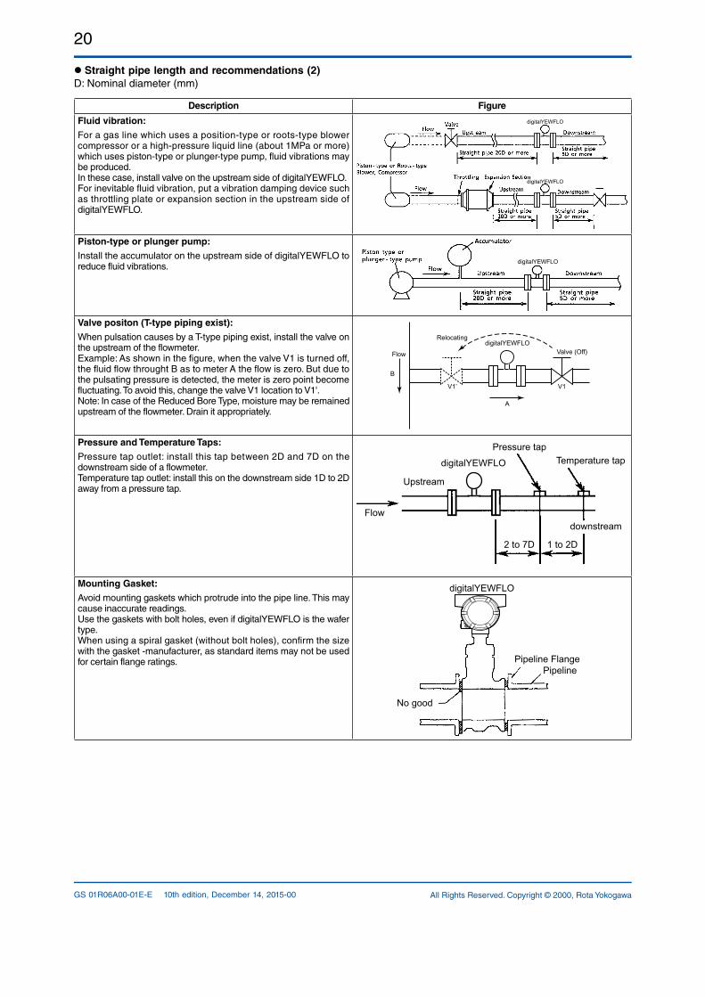
Straight pipe length and recommendations (2)D: Nominal diameter (mm)
Description Figure
Fluid vibration:
For a gas line which uses a positiontype or rootstype blower compressor or a highpressure liquid line (about 1MPa or more) which uses pistontype or plungertype pump, fluid vibrations may be produced.In these case, install valve on the upstream side of digitalYEWFLO.For inevitable fluid vibration, put a vibration damping device such as throttling plate or expansion section in the upstream side of digitalYEWFLO.
digitalYEWFLO
digitalYEWFLO
Piston-type or plunger pump:
Install the accumulator on the upstream side of digitalYEWFLO to reduce fluid vibrations.
digitalYEWFLO
Valve positon (T-type piping exist):
When pulsation causes by a Ttype piping exist, install the valve on the upstream of the flowmeter.Example: As shown in the figure, when the valve V1 is turned off, the fluid flow throught B as to meter A the flow is zero. But due to the pulsating pressure is detected, the meter is zero point become fluctuating. To avoid this, change the valve V1 location to V1'.Note: In case of the Reduced Bore Type, moisture may be remained upstream of the flowmeter. Drain it appropriately.
Relocating
Valve (Off)
A
B
Flow
V1’ V1
digitalYEWFLO
Pressure and Temperature Taps:
Pressure tap outlet: install this tap between 2D and 7D on the downstream side of a flowmeter.Temperature tap outlet: install this on the downstream side 1D to 2D away from a pressure tap.
Pressure tapTemperature tap
Upstream
Flowdownstream
2 to 7D 1 to 2D
digitalYEWFLO
Mounting Gasket:
Avoid mounting gaskets which protrude into the pipe line. This may cause inaccurate readings.Use the gaskets with bolt holes, even if digitalYEWFLO is the wafer type.When using a spiral gasket (without bolt holes), confirm the size with the gasket manufacturer, as standard items may not be used for certain flange ratings. Pipeline Flange
Pipeline
No good
digitalYEWFLO
21
All Rights Reserved. Copyright © 2000, Rota Yokogawa GS 01R06A00-01E-E 10th edition, December 14, 2015-00
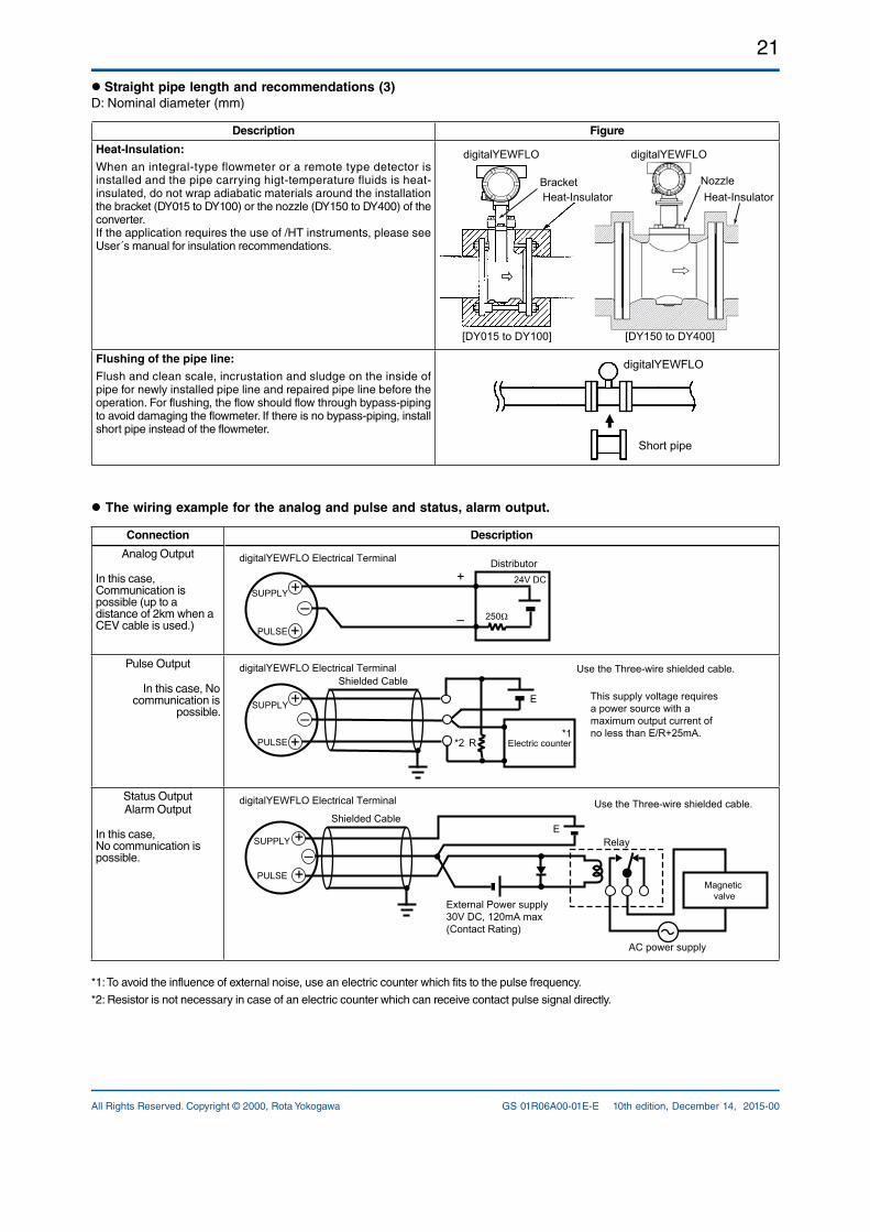
Straight pipe length and recommendations (3)D: Nominal diameter (mm)
Description Figure
Heat-Insulation:
When an integraltype flowmeter or a remote type detector is installed and the pipe carrying higttemperature fluids is heatinsulated, do not wrap adiabatic materials around the installation the bracket (DY015 to DY100) or the nozzle (DY150 to DY400) of the converter.If the application requires the use of /HT instruments, please see User´s manual for insulation recommendations.
[DY015 to DY100] [DY150 to DY400]
Bracket NozzleHeat-Insulator Heat-Insulator
digitalYEWFLO digitalYEWFLO
Flushing of the pipe line:
Flush and clean scale, incrustation and sludge on the inside of pipe for newly installed pipe line and repaired pipe line before the operation. For flushing, the flow should flow through bypasspiping to avoid damaging the flowmeter. If there is no bypasspiping, install short pipe instead of the flowmeter.
Short pipe
digitalYEWFLO
The wiring example for the analog and pulse and status, alarm output.
Connection Description
Analog Output
In this case, Communication is possible (up to a distance of 2km when a CEV cable is used.)
digitalYEWFLO Electrical Terminal
250Ω
24V DC+
–
Distributor
PULSE
SUPPLY +–
+
Pulse Output
In this case, No communication is
possible.This supply voltage requires a power source with a maximum output current of no less than E/R+25mA.
R
E
digitalYEWFLO Electrical Terminal Use the Three-wire shielded cable.
Electric counter*1
*2
Shielded Cable
PULSE
SUPPLY +–
+
Status OutputAlarm Output
In this case,No communication ispossible.
Use the Three-wire shielded cable.Shielded Cable
PULSE
SUPPLY +–
+Magnetic
valve
AC power supply
External Power supply 30V DC, 120mA max(Contact Rating)
digitalYEWFLO Electrical Terminal
ERelay
*1: To avoid the influence of external noise, use an electric counter which fits to the pulse frequency.
*2: Resistor is not necessary in case of an electric counter which can receive contact pulse signal directly.
22
All Rights Reserved. Copyright © 2000, Rota YokogawaGS 01R06A00-01E-E 10th edition, December 14, 2015-00
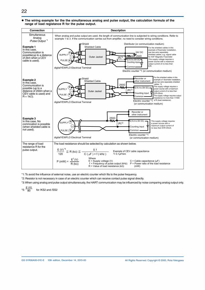
The wiring example for the the simultaneous analog and pulse output, the calculation formula of the range of load registance R for the pulse output.
Connection Description
Simultaneous Analog
Pulse Output *3
Example 1In this case, Communication is possible(up to a distance of 2km when a CEV cable is used).
Example 2In this case, Communication is possible (up to a distance of 200m when a CEV cable is used) and R = 1kΩ).
Example 3In this case, No commcation is possible (when shielded cable is not used).
250Ω+
–+PULSE
SUPPLY
digitalYEWFLO Electrical Terminal
Recorder or other instrument
This supply voltage requires a power sourse with a maximum output current of no less than E/R+25mA.
Electric counter *1
E(16.4 to 30V DC)
Counting input
Common
(or communication medium)
When analog and pulse output are used, the length of communication line is subjected to wiring conditions. Refer to example 1 to 3. If the communication carries out from amplifier, no need to consider wiring conditions.
+–
+
For the shielded cables in this example of flowmeter installation, use two-wire separately shielded cables. *4This supply voltage requires a power sourse with a maximum output current of no less than E/R+25mA.The supply voltage requires output impedance no more than 1/1000 of R (load resistance).
PULSE
SUPPLY
Shielded CableShield
digitalYEWFLO Electrical Terminal
Outer Jacket
(or communication medium)
250Ω
(R)*2Counting inputCommon
Recorder or other instrument
Electric counter *1
E(16.4 to 30V DC)
(R)*2
Electric counter *1 (or communication medium)
+–
+250Ω(R)*2
E(10.5 to 30V DC) Counting input
Common
24V DC
PULSE
SUPPLY
Distributor (or communication medium)Shielded Cable
Shield
digitalYEWFLO Electrical Terminal
For the shielded cables in this example of flowmeter installation, use two-wire separately shielded cables. e.g. signal cable for AXF Magnetic FlowmeterThis supply voltage requires a power sourse with a maximum output current of no less than E/R.
Outer Jacket
The range of load resistance R for the pulse output.
The load resistance should be selected by calculation as shown below.
0.1 C ( µF ) × f ( kHz )
R (kΩ)120
E (V) Example of CEV cable capacitance 0.1µF/km
WhereE = Supply voltage (V) f = Frequency of pulse output (kHz)R = Value of load resistance (kΩ)
C = Cable capacitance (µF) P = Power ratio of the load resistance (mW)
P (mW) =R (kΩ)E2 (V)
*5
*1: To avoid the influence of external noise, use an electric counter which fits to the pulse frequency.
*2: Resistor is not necessary in case of an electric counter which can receive contact pulse signal directly.
*3: When using analog and pulse output simultaneously, the HART communication may be influenced by noise comparing analog output only.
*5: E (V)
80 for /KS2 and /SS2
23
All Rights Reserved. Copyright © 2000, Rota Yokogawa GS 01R06A00-01E-E 10th edition, December 14, 2015-00
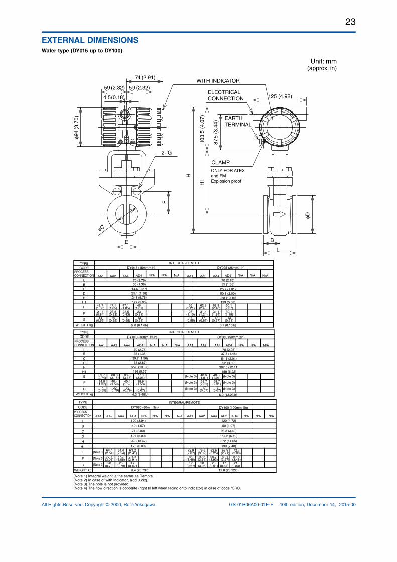
EXTERNAL DIMENSIONSWafer type (DY015 up to DY100)
Unit: mm(approx. in)
H1
H
125 (4.92)
L
φD
B
φC
2-fG
74 (2.91)
F
E
59 (2.32)
4.5(0.18)
59 (2.32)ELECTRICAL CONNECTION
CLAMP
WITH INDICATOR
EARTH TERMINAL
φ94
(3.7
0)
103.
5 (4
.07)
87.5
(3.
44)
ONLY FOR ATEXand FM Explosion proof
6.0 (13.23lb)4.3 (9.48lb)
AA1 AA2 AA4 AA1 AA2 AA470 (2.76)
39.7 (1.56)73 (2.87)
69.7(2.74)
80.8(3.18)
80.8(3.18)
77.8(3.06)
34.8(1.37)
40.4(1.59)
40.4(1.59)
38.9(1.53)
17(0.67)
14(0.55)
20(0.79)
20(0.79)
48.6(1.91)
48.6(1.91)
58.7(2.31)
58.7(2.31)
17(0.67)
17(0.67)
75 (2.95)35 (1.38) 37.5 (1.48)
92 (3.62)51.1 (2.01)
158 (6.22)307.5 (12.11)
136 (5.35)276 (10.87)
12.8 (28.22lb)9.4 (20.73lb)
372 (14.65)
190 (7.48)
342 (13.47)
175 (6.89)
157.2 (6.19)
93.8 (3.69)
50 (1.97)
120 (4.72)
72.7(2.86)
68.9(2.71)
82.6(3.25)
76.6(3.02)
72.9(2.87)
87.8(3.46)
83.1(3.27)
99.7(3.93)
88(3.46)
92.5(3.64)
21(0.83)
23(0.91)
17(0.67)
17(0.67)
20(3.06)
20(0.79)
20(0.79)
17(0.67)
77.7(3.06)
77.7(3.06)
73.9(2.91)
AD2
61.2(2.41)
64.4(2.54)
64.4(2.54)
127 (5.00)
71 (2.80)
40 (1.57)
100 (3.94)
DY080 (80mm,3in)
AA4AA2AA1AA4AA2AA1
DY100 (100mm,4in)
AD4
INTEGRAL/REMOTE
(Note 1) Integral weight is the same as Remote.(Note 2) In case of with Indicator, add 0.2kg.(Note 3) The hole is not provided.(Note 4) The flow direction is opposite (right to left when facing onto indicator) in case of code /CRC.
L
CDH
H1
E
F
G
DY040 (40mm,11/2 in) DY050 (50mm,2in)
B
INTEGRAL/REMOTE
B
G
F
E
H1
H
D
C
L
TYPECODE
PROCESSCONNECTION
TYPE
CODEPROCESSCONNECTION
3.7 (8.16lb)2.8 (6.17lb)
258 (10.16)129 (5.08)
50.8 (2.00)25.7 (1.01)
70 (2.76)
60.1(2.37)
62.9(2.48)
62.9(2.48)
56(2.21)
30.1(1.19)
31.4(1.24)
31.4(1.24)
28(1.10)
13(0.51)
14(0.55)
17(0.67)
17(0.67)
DY025 (25mm,1in)
14(0.55)
14(0.55)
14(0.55)
13(0.51)
23(0.91)
23.5(0.93)
23.5(0.93)
21.4(0.84)
46(1.81)
47.1(1.85)
47.1(1.85)
42.7(1.68)
127 (5.00)
35.1 (1.38)248 (9.76)
14.6 (0.57)
70 (2.76)35 (1.38)35 (1.38)
DY015 (15mm,1/2 in)
AA4AA2AA1AD4AA4AA2AA1
G
F
E
H1HDC
L
PROCESSCONNECTION
B
INTEGRAL/REMOTETYPECODE
WEIGHT kg
WEIGHT kg
WEIGHT kg
(Note 3)
(Note 3)
(Note 3)
(Note 3)
(Note 3)
(Note 3)
(Note 3)
(Note 3)
(Note 3)
N/A N/A N/A N/A N/A N/A
N/A N/A N/A N/A N/A N/A
N/A N/A N/A N/A N/A N/A
AD4
AD4 AD4
N/A AD4

24
All Rights Reserved. Copyright © 2000, Rota YokogawaGS 01R06A00-01E-E 10th edition, December 14, 2015-00
Flange type (DY015 up to DY100)
Unit: mm(approx. in)
125(4.92)
87.5
(3.4
4)
103.
5(4.
07)
H1
φD
H
N-φG
φJφC
4.5(0.18)
59(2.32) 59(2.32)
74(2.91)
φ94(
3.70
)
L
T
CLAMP
EARTH TERMINAL
ELECTRICAL CONNECTION
WITH INDICATOR
ONLY FOR ATEXand FM Explosion proof
6.94.2
25.4(1.00)
101.6(4.00)
34.9(1.37)
307(12.09)
149.4(5.88)
150(5.91)
190(7.48)
22.4(0.88)
82.6(3.25)
28.8(1.13)
291(11.46)
120.7(4.75)
130(5.12)
160(6.30)
INTEGRAL/REMOTE
85(3.35)
89(3.50)
89(3.50)
79.2(3.12)
4 (0.16)15.7
(0.62)
25.7 (1.01)
150(5.91)
DY025 (25mm,1in)
14(0.55)
15.7(0.62)
15.7(0.62)
15.7(0.62)
4 (0.16)
65(2.56)
66.5(2.62)
66.5(2.62)
60.5(2.38)
D
14.6 (0.58)
130(5.12)
BD4BD4BA1 BA2 BA4 LA5
BA1 BA2 BA4 BA5
BA1 BA2 BA4 BA5 BA1 BA2 BA4 BA5
BA1 BA2 BA4 BA5
BA1 BA2 BA4 LA5PROCESSCONNECTION
TYPE
CODE
L
C
H
H1
T
J
N
G
95(3.74)
88.9(3.50)
95.3(3.75)
95.3(3.75)
275(10.83)
278(10.94)
278(10.94)
278(10.94)
127 (5.00)11.2
(0.44)14.2
(0.56)21
(0.83)16
(0.63)
108(4.25)
124(4.88)
124(4.88)
115(4.53)
286.5(11.28)
294.5(11.59)
294.5(11.59)
290(11.42)
14.2(0.56)
17.5(0.69)
24(0.94)
18(0.71)
129 (5.08)
19(0.75)
19(0.75)
14(0.55)
4.1 4.3 4.6 6.6 7.2 7.7 kg
lb
WEIGHT
kg
lb
WEIGHT
kg
lb
WEIGHT
6.7
15.7(0.62)
66.5(2.62)
19.9(0.78)
278(10.94)
95.3(3.75)
140(5.51)
CA4
4.5
22.4(0.88)
82.6(3.25)
28.8(1.13)
291(11.46)
120.7(4.75)
160(6.30)
RA5
6.8 11.1
19(0.75)
89(3.50)
24(0.94)
294.5(11.59)
124(4.88)
170(6.69)
CA4
7.9
25.4(1.00)
101.6(4.00)
34.9(1.37)
307(12.09)
149.4(5.88)
190(7.48)
RA5
11.4
15.219.269.04 9.48 10.14 14.55 15.88 16.9814.77 9.92 14.99 24.48 17.42 25.14
11.38.8
25.4(1.00)
8(0.31)
165.1(6.50)
44.5(1.75)
369.5(14.55)
215.9(8.50)
170(6.69)
230(9.06)
28.4(1.12)
124(4.88)
38.2(1.50)
328.5(12.93)
177.8(7.00)
150(5.91)
200(7.87)
DY050 ( 50mm, 2in)
D
DY040 (40mm,11/2 in)
BD4BD4
L
C
H
H1
T
J
N
G
150(5.91)
39.7 (1.56)127
(5.00)155.4(6.12)
155.4(6.12)
150(5.91)
303(11.93)
317(12.48)
317(12.48)
314.5(12.38)
136 (5.35)18
(0.71)17.5
(0.69)20.6
(0.81)28.8
(1.13)98.6
(3.88)114.3(4.50)
114.3(4.50)
110(4.33)
4(0.16)
15.7(0.62)
22.4(0.88)
22.4(0.88)
18(0.71)
170(6.69)
51.1 (2.01)165
(6.50)152.4(6.00)
165.1(6.50)
165.1(6.50)
344(13.54)
344(13.54)
344(13.54)
337.5(13.29)
158 (6.22)19.1
(0.75)22.4
(0.88)31.8
(1.25)20
(0.79)120.7(4.75)
127(5.00)
127(5.00)
125(4.92)
4(0.16)
4(0.16)
8(0.31)
8(0.31)
19(0.75)
19(0.75)
19(0.75)
18(0.71)
8.1 9.3 11.3 11.7 13.2 14.8
INTEGRAL/REMOTE
PROCESSCONNECTION
TYPE
CODE
16.2
22.4(0.88)
114.3(4.50)
28.8(1.13)
317(12.48)
155.4(6.12)
185(7.28)
CA4
11.7
28.4(1.12)
124(4.88)
38.2(1.50)
328.5(12.93)
177.8(7.00)
200(7.87)
CA5
16.3 26.5
19(0.75)
8(0.31)
127(5.00)
33.3(1.31)
344(13.54)
165.1(6.50)
205(8.07)
CA4
15.8
25.4(1.00)
8(0.31)
165.1(6.50)
46(1.81)
369.5(14.55)
215.9(8.50)
230(9.06)
CA5
26.9
24.9219.4017.86 20.51 24.92 25.80 29.11 32.6335.72 25.80 35.94 58.43 34.84 59.31
27.423.22019.4
31.8(1.25)
235(9.25)
50.9(2.00)
439.5(17.30)
292.1(11.50)
280(11.02)
200(7.87)
25.4(1.00)
8(0.31)
190.5(7.50)
44.5(1.75)
399(15.71)
209.6(8.25)
245(9.65)
DY100 (100mm, 4in)
D
DY080 (80mm, 3in)
L
C
H
H1
T
J
N
G
BD2 BD4 BD2 BD4200
(7.87)
71 (2.80)200
(7.87)200
(7.87)190.5(7.50)
209.6(8.25)
241.3(9.50)
374(14.72)
383.5(15.10)
383.5(15.10)
378.5(14.90)
378.5(14.90)
175 (6.89)23.9
(0.94)28.4
(1.12)38.2
(1.50)20
(0.79)24
(0.95)160
(6.30)160
(6.30)152.4(6.00)
168.2(6.62)
168(6.61)
8(0.31)
8(0.31)
8(0.31)
8(0.31)
19(0.75)
22.4(0.88)
22.4(0.88)
18(0.71)
18(0.71)
4(0.16)
220(8.66)
220(8.66)
240(9.45)
93.8 (3.69)228.6(9.00)
254(10.00)
273(10.75)
220(8.66)
235(9.25)
409(16.10)
420.5(16.56)
430(16.93)
403.5(15.89)
411(16.18)
190 (7.48)24
(0.95)23.9
(0.94)31.8
(1.25)44.5
(1.75)20
(0.79)190.5(7.50)
200.2(7.88)
216(8.50)
180(7.09)
190(7.48)
8(0.31)
19(0.75)
22.4(0.88)
25.4(1.00)
18(0.71)
22(0.87)
20 23.8 25.4 27.4 35.9 50.8
INTEGRAL/REMOTE
PROCESSCONNECTION
TYPE
CODE
35.7
22.4(0.88)
8(0.31)
170(6.69)
39.7(1.56)
383.5(15.10)
235(9.25)
CA4
209.6(8.25)
27.1
25.4(1.00)
8(0.31)
180(7.09)
46(1.81)
399(15.71)
250(9.84)
CA5
241.3(9.50)
36.3 55.9
25.4(1.00)
216(8.50)
46(1.81)
430(16.93)
273(10.75)
270(10.63)
CA4
52.8
31.8(1.25)
235(9.25)
52.4(2.06)
439.5(17.30)
292.1(11.50)
285(11.22)
CA5
56.6
60.4251.1644.1042.7844.10 52.48 56.01 60.42 79.16 112.0178.72 59.76 80.04 123.26 116.42 124.80
(Note 1) Integral weight is the same as Remote(Note 2) In the case of with Indicator, add 0.2 kg(Note 3) The flow direction is opposite (right to left when facing onto indicator) in case of code/ /CRC.
DY015 (15mm, 1/2 in)
5.4
75(2.95)
BD6
105(4.13)283
(11.14)
20(0.79)
12.7
BD6
170(6.69)324.5
(12.78)
125(4.92)
2724.1
BD5 BD6
2158.47)
230(9.06)
386(15.2)
393.5(15.50)
28(1.10)
32(1.26)
170(6.69)
180(7.09)
22(0.04)
26(1.02)
BD7
5.4
BD7
12.7
325(12.8)
28(1.10)
180(7.09)
BD7230
(9.06)
26
394(15.52
36(1.42)
14(0.55)
14(0.55)
8(0.31)
8(0.31)
8(0.31)
57.3359.5353.14
28.0028.00
11.9111.91
26(1.02)
180(7.09)
230(9.06)
22(0.04)
22(0.04)
26(1.02)
125(4.92)
170(6.69)
75(2.95)
20(0.79)
105(4.13)283
(11.14)
9.6
100(3.93
BD6
302.5(11.91)
18(0.71)
15.214.3
BD5 BD6
351.5(13.84)
359(14.14)
135(5.32)
145(5.71)
22(0.87)
39.733
BD5 BD6
250(9.85)
265(10.43)
418.5(16.48)
426(16.78)
30(1.18)
36(1.42)
200(7.88)
210(8.27)
26(1.02)
BD7
9.6
303(11.93
BD7195
(7.68)
15.2
30(1.18)
BD7260
(10.24)
39.7
40(1.57)
265(10.43)
426(16.78)
210(8.27)
30(1.18)
30(1.18)
180(7.09)
195(7.68)
195(7.68)
359(14.14)
26(1.02)
28(1.10)
4(0.16)
4(0.16)
4(0.16)26
(1.02)26
(1.02)
145(5.71)
150(5.91)
170(6.69)
140(5.51)
140(5.51)
24(0.94)
24(0.94)100
(3.93
18(0.71)
21.16 21.16
31.52 33.50 33.50
72.74 87.51 87.51
N/AN/A
N/A
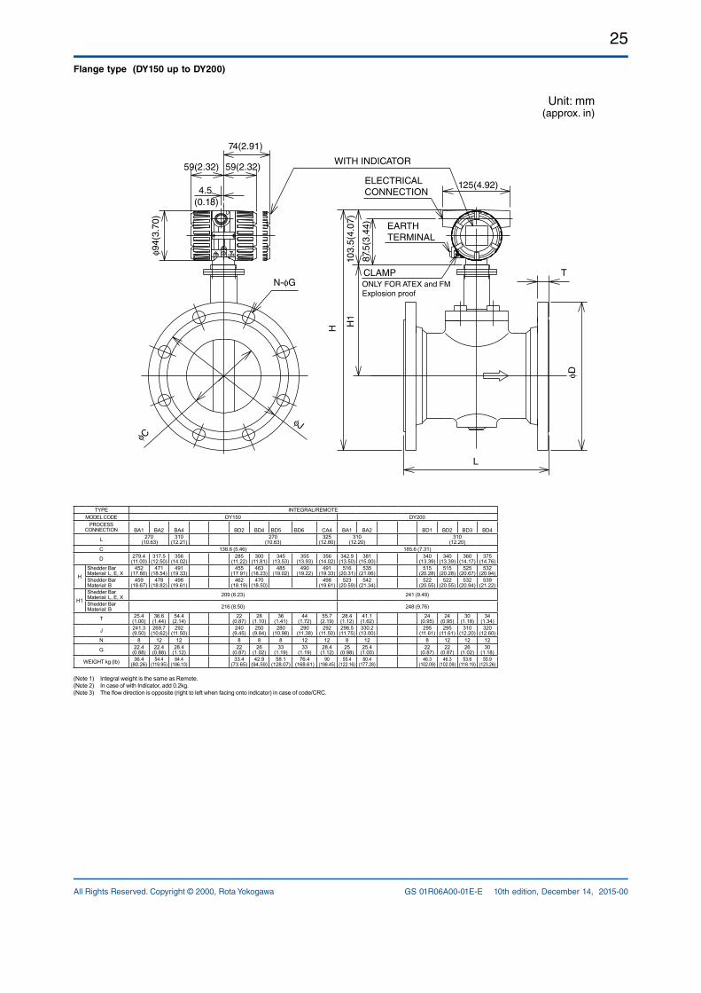
25
All Rights Reserved. Copyright © 2000, Rota Yokogawa GS 01R06A00-01E-E 10th edition, December 14, 2015-00
Flange type (DY150 up to DY200)
Unit: mm(approx. in)
TYPE INTEGRAL/REMOTEMODEL CODE DY150 DY200
PROCESSCONNECTION BA1 BA2 BA4 BD2 BD4 BD5 BD6 CA4 BA1 BA2 BD1 BD2 BD3 BD4
L 270 (10.63)
310 (12.21)
270 (10.63)
325 (12.80)
310(12.20)
310(12.20)
C 138.8 (5.46) 185.6 (7.31)
D 279.4 (11.00)
317.5 (12.50)
356 (14.02)
285 (11.22)
300 (11.81)
345 (13.53)
355 (13.93)
356 (14.02)
342.9 (13.50)
381 (15.00)
340 (13.39)
340 (13.39)
360 (14.17)
375 (14.76)
HShedder Bar Material: L, E, X
452 (17.80)
471 (18.54)
491 (19.33)
455 (17.91)
463 (18.23)
485 (19.02)
490 (19.22)
491 (19.33)
516 (20.31)
535 (21.06)
515 (20.28)
515 (20.28)
525 (20.67)
532 (20.94)
Shedder Bar Material: B
459 (18.67)
478 (18.82)
498 (19.61)
462 (18.19)
470 (18.50)
498 (19.61)
523 (20.59)
542 (21.34)
522 (20.55)
522 (20.55)
532 (20.94)
539 (21.22)
H1Shedder Bar Material: L, E, X 209 (8.23) 241 (9.49)
Shedder Bar Material: B 216 (8.50) 248 (9.76)
T 25.4 (1.00)
36.6 (1.44)
54.4 (2.14)
22(0.87)
28 (1.10)
36 (1.41)
44 (1.72)
55.7 (2.19)
28.4 (1.12)
41.1 (1.62)
24 (0.95)
24 (0.95)
30 (1.18)
34 (1.34)
J 241.3 (9.50)
269.7 (10.62)
292 (11.50)
240 (9.45)
250 (9.84)
280 (10.98)
290 (11.38)
292(11.50)
298.5 (11.75)
330.2 (13.00)
295 (11.61)
295 (11.61)
310 (12.20)
320 (12.60)
N 8 12 12 8 8 8 12 12 8 12 8 12 12 12
G 22.4 (0.88)
22.4 (0.88)
28.4 (1.12)
22 (0.87)
26 (1.02)
33 (1.19)
33 (1.19)
28.4 (1.12)
25 (0.98)
25.4 (1.00)
22 (0.87)
22 (0.87)
26 (1.02)
30 (1.18)
WEIGHT kg (lb) 36.4 (80.26)
54.4 (119.95)
84.4 (186.10)
33.4 (73.65)
42.9 (94.59)
58.1 (128.07)
76.4 (168.61)
90 (198.45)
55.4 (122.16)
80.4 (177.28)
46.3 (102.09)
46.3 (102.09)
53.6 (118.19)
55.9 (123.26)
(Note 1) Integral weight is the same as Remote.(Note 2) In case of with Indicator, add 0.2kg.(Note 3) The flow direction is opposite (right to left when facing onto indicator) in case of code/CRC.
ONLY FOR ATEX and FM Explosion proof
CLAMP
ELECTRICALCONNECTION
WITH INDICATOR
H
125(4.92)
φCφJ
N-φG
74(2.91)φ9
4(3.
70)
59(2.32) 59(2.32)
4.5(0.18)
φD
L
T
H1
103.
5(4.
07)
87.5
(3.4
4) EARTH TERMINAL
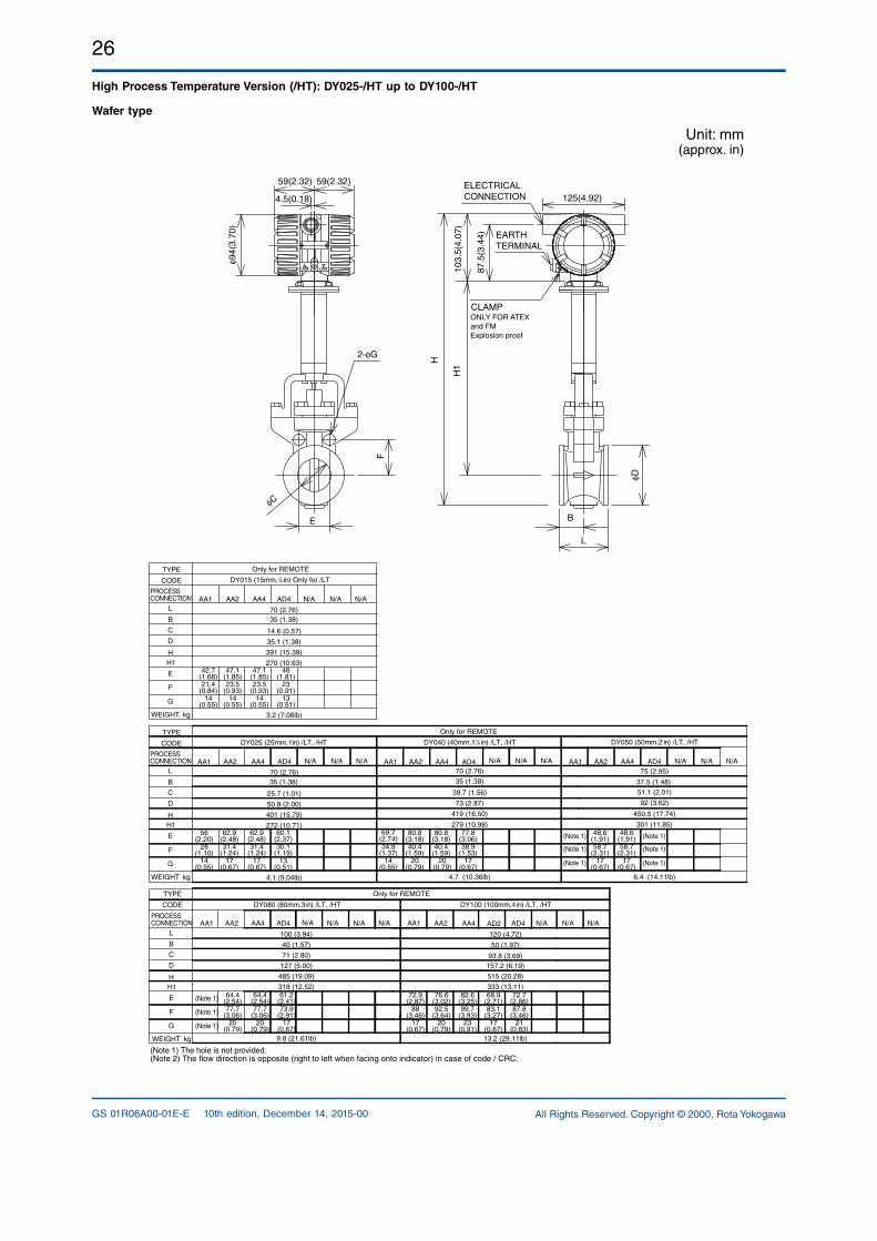
26
All Rights Reserved. Copyright © 2000, Rota YokogawaGS 01R06A00-01E-E 10th edition, December 14, 2015-00
High Process Temperature Version (/HT): DY025-/HT up to DY100-/HT
Wafer type
Unit: mm(approx. in)
φC
2-φG
4.5(0.18)
59(2.32)59(2.32)
φ94(
3.70
)
F
E
ONLY FOR ATEXand FM Explosion proof
H1
103.
5(4.
07)
B
H
125(4.92)
L
φD
87.5
(3.4
4)
ELECTRICAL CONNECTION
CLAMP
EARTH TERMINAL
DY015 (15mm,1/2 in) Only for /LT
Only for REMOTE
515 (20.28)
333 (13.11)
485 (19.09)
318 (12.52)
157.2 (6.19)93.8 (3.69)
50 (1.97)
120 (4.72)
72.7(2.86)
68.9(2.71)
82.6(3.25)
76.6(3.02)
72.9(2.87)
87.8(3.46)
83.1(3.27)
99.7(3.93)
88(3.46)
92.5(3.64)
21(0.83)
23(0.91)
17(0.67)
17(0.67)
20(0.79)
20(0.79)
20(0.79)
17(0.67)
77.7(3.06)
77.7(3.06)
73.9(2.91)
AD4
61.2(2.41)
64.4(2.54)
64.4(2.54)
127 (5.00)
71 (2.80)
40 (1.57)
100 (3.94)
DY080 (80mm,3 in) /LT, /HT
AA4AA2AA1 AD2AA4AA2AA1
DY100 (100mm,4 in) /LT, /HT
AD4
AA1 AA2 AA4 AA1 AA2 AA4
DY040 (40mm,11/2 in) /LT, /HT
70 (2.76)
39.7 (1.56)
73 (2.87)
69.7(2.74)
80.8(3.18)
80.8(3.18)
77.8(3.06)
34.8(1.37)
40.4(1.59)
40.4(1.59)
38.9(1.53)
17(0.67)
14(0.55)
20(0.79)
20(0.79)
DY050 (50mm,2 in) /LT, /HT
48.6(1.91)
48.6(1.91)
58.7(2.31)
58.7(2.31)
17(0.67)
17(0.67)
(Note 1)
(Note 1)
(Note 1)
(Note 1)
(Note 1)
(Note 1)
(Note 1)
(Note 1)
(Note 1)
75 (2.95)
92 (3.62)
51.1 (2.01)
301 (11.85)
450.5 (17.74)
279 (10.98)
419 (16.50)
AA1 AA2 AA4
DY025 (25mm,1in) /LT, /HT
17(0.67)
17(0.67)
14(0.55)
13(0.51)
28(1.10)
31.4(1.24)
31.4(1.24)
30.1(1.19)
56(2.20)
62.9(2.48)
62.9(2.48)
60.1(2.37)
70 (2.76)
25.7 (1.01)
50.8 (2.00)
272 (10.71)
401 (15.79)
Only for REMOTE
Only for REMOTE
4.1 (9.04lb) 4.7 (10.36lb) 6.4 (14.11lb)
13.2 (29.11lb)9.8 (21.61lb)
(Note 1) The hole is not provided.(Note 2) The flow direction is opposite (right to left when facing onto indicator) in case of code / CRC.
35 (1.38) 35 (1.38) 37.5 (1.48)
kgWEIGHT
D
L
C
HH1
B
E
F
G
PROCESSCONNECTION
TYPE
CODE
AA1 AA2 AA4 AD4
14(0.55)
14(0.55)
14(0.55)
13(0.51)
21.4(0.84)
23.5(0.93)
23.5(0.93)
23(0.91)
42.7(1.68)
47.1(1.85)
47.1(1.85)
46(1.81)
70 (2.76)
14.6 (0.57)
35.1 (1.38)
270 (10.63)
391 (15.39)
3.2 (7.06lb)
35 (1.38)
kgWEIGHT
D
L
C
HH1
B
E
F
G
PROCESSCONNECTION
TYPE
CODE
kgWEIGHT
D
L
C
HH1
B
E
F
G
PROCESSCONNECTION
TYPE
CODE
N/A N/A N/A
N/A N/A N/A N/A N/A N/A N/A N/A N/A
N/A N/A N/AN/A N/A N/A
AD4 AD4 AD4
N/A
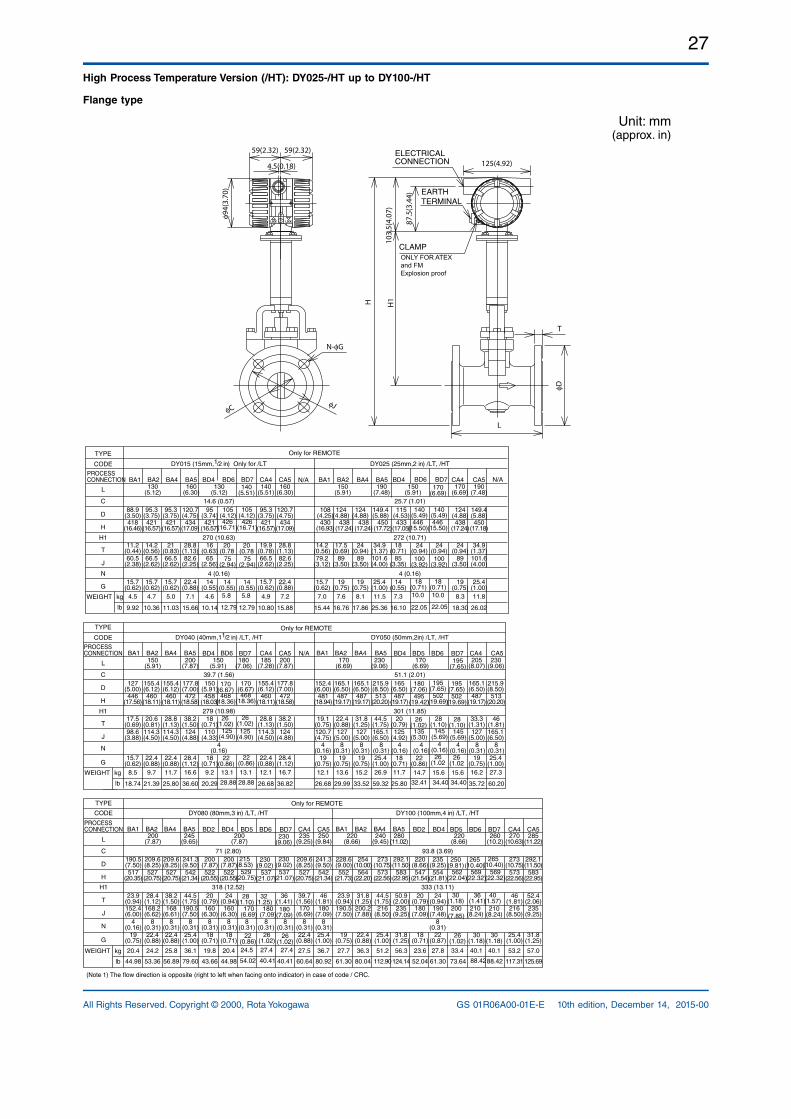
27
All Rights Reserved. Copyright © 2000, Rota Yokogawa GS 01R06A00-01E-E 10th edition, December 14, 2015-00
High Process Temperature Version (/HT): DY025-/HT up to DY100-/HT
Flange type
Unit: mm(approx. in)
φCφJ
N-φG
φD
H
59(2.32)
4.5(0.18)
59(2.32)
H1
T
L
103.
5(4.
07)
87.5
(3.4
4)
φ94(
3.70
)
125(4.92)ELECTRICAL CONNECTION
CLAMP
EARTH TERMINAL
ONLY FOR ATEXand FM Explosion proof
BA1 BA2 BA4 BA5 BA1 BA2 BA4 BA5
kg
lb
WEIGHT 8.37.34.6
25.4(1.00)
101.6(4.00)
34.9(1.37)
450(17.72)
149.4(5.88)
150(5.91)
170(6.69)
190(7.48)
22.4(0.88)
82.6(2.25)
28.8(1.13)
434(17.09)
120.7(4.75)
130(5.12)
160(6.30)
DY025 (25mm,2 in) /LT, /HT
D
DY015 (15mm,1/2 in) Only for /LT
BD4BD4
L
C
H
H1
T
J
N
G
130(5.12)
14.6 (0.57)88.9
(3.50)95.3
(3.75)95.3
(3.75)95
(3.74)418
(16.46)421
(16.57)421
(16.57)421
(16.57)
270 (10.63)16
(0.63)11.2
(0.44)14.2
(0.56)21
(0.83)60.5
(2.38)66.5
(2.62)66.5
(2.62)65
(2.56)
4 (0.16)15.7
(0.62)15.7
(0.62)15.7
(0.62)14
(0.55)
CA4150
(5.91)25.7 (1.01)115
(4.53)108
(4.25)124
(4.88)124
(4.88)124
(4.88)438
(17.24)438
(17.24)433
(17.05)430
(16.93)438
(17.24)
272 (10.71)14.2
(0.56)17.5
(0.69)24
(0.94)18
(0.71)24
(0.94)79.2
(3.12)89
(3.50)89
(3.50)85
(3.35)89
(3.50)
4 (0.16)15.7
(0.62)19
(0.75)19
(0.75)14
(0.55)19
(0.75)4.5 4.7 5.0 7.0 7.6 8.1
PROCESSCONNECTION
TYPE
CODE
7.1
15.7(0.62)
66.5(2.62)
19.9(0.78)
421(16.57)
95.3(3.75)
140(5.51)
CA4
4.9
22.4(0.88)
82.6(2.25)
28.8(1.13)
434(17.09)
120.7(4.75)
160(6.30)
CA5
7.2 11.5
25.4(1.00)
101.6(4.00)
34.9(1.37)
450(17.18)
149.4(5.88)
190(7.48)
CA5
11.8
18.3016.1010.149.92 10.36 11.03 15.44 16.76 17.8615.66 10.80 15.88 25.36 26.02
BA1 BA2 BA4 BA5 BA1 BA2 BA4 BA5
kg
lb
WEIGHT 11.79.2
25.4(1.00)
25.4(1.00)
165.1(6.50)
165.1(6.50)
44.5(1.75)
46(1.81)
513(20.20)
513(20.20)
215.9(8.50)
215.9(8.50)
170(6.69)
230(9.06)
230(9.06)
28.4(1.12)
124(4.88)
38.2(1.50)
472(18.58)
177.8(7.00)
150(5.91)
200(7.87)
DY050 (50mm,2in) /LT, /HT
D
DY040 (40mm,11/2 in) /LT, /HT
BD4BD4
L
C
H
H1
T
J
N
G
150(5.91)
39.7 (1.56)127
(5.00)155.4(6.12)
155.4(6.12)
150(5.91)
446(17.56)
460(18.11)
460(18.11)
458(18.03)
279 (10.98)18
(0.71)17.5
(0.69)20.6
(0.81)28.8
(1.13)98.6
(3.88)114.3(4.50)
114.3(4.50)
110(4.33)
4(0.16)
15.7(0.62)
22.4(0.88)
22.4(0.88)
18(0.71)
CA4170
(6.69)51.1 (2.01)165
(6.50)152.4(6.00)
165.1(6.50)
165.1(6.50)
487(19.17)
487(19.17)
487(19.17)
481(18.94)
301 (11.85)19.1
(0.75)22.4
(0.88)31.8
(1.25)20
(0.79)120.7(4.75)
127(5.00)
127(5.00)
125(4.92)
4(0.16)
4(0.16)
8(0.31)
8(0.31)
8(0.31)
8(0.31)
8(0.31)
19(0.75)
19(0.75)
19(0.75)
18(0.71)
8.5 9.7 11.7 12.1 13.6 15.2
PROCESSCONNECTION
TYPE
CODE
16.6
22.4(0.88)
114.3(4.50)
28.8(1.13)
460(18.11)
155.4(6.12)
185(7.28)
CA4
12.1
28.4(1.12)
124(4.88)
38.2(1.50)
472(18.58)
177.8(7.00)
200(7.87)
CA5
16.7 26.9
19(0.75)
127(5.00)
33.3(1.31)
487(19.17)
165.1(6.50)
205(8.07)
CA5
16.2 27.3
25.8020.2918.74 21.39 25.80 26.68 29.99 33.5236.60 26.68 36.82 59.32 35.72 60.20
(Note 1) The flow direction is opposite (right to left when facing onto indicator) in case of code / CRC.
BA1 BA2 BA4 BA5 BA1 BA2 BA4 BA5
kg
lb
WEIGHT 27.823.620.419.8
31.8(1.25)
235(9.25)
50.9(2.00)
583(22.95)
292.1(11.50)
280(11.02)
200(7.87)
25.4(1.00)
8(0.31)
190.5(7.50)
44.5(1.75)
542(21.34)
209.6(8.25)
245(9.65)
DY100 (100mm,4 in) /LT, /HT
D
DY080 (80mm,3 in) /LT, /HT
L
C
H
H1
T
J
N
G
BD2 BD4 BD2 BD4200
(7.87)
71 (2.80)200
(7.87)200
(7.87)190.5(7.50)
209.6(8.25)
241.3(9.50)
517(20.35)
527(20.75)
527(20.75)
522(20.55)
522(20.55)
318 (12.52)23.9
(0.94)28.4
(1.12)38.2
(1.50)20
(0.79)24
(0.94)160
(6.30)160
(6.30)152.4(6.00)
168.2(6.62)
168(6.61)
8(0.31)
8(0.31)
8(0.31)
8(0.31)
19(0.75)
22.4(0.88)
22.4(0.88)
18(0.71)
18(0.71)
4(0.16)
220(8.66)
220(8.66)
240(9.45)
93.8 (3.69)228.6(9.00)
254(10.00)
273(10.75)
220(8.66)
235(9.25)
552(21.73)
564(22.20)
573(22.56)
547(21.54)
554(21.81)
333 (13.11)24
(0.94)23.9
(0.94)31.8
(1.25)44.5
(1.75)20
(0.79)190.5(7.50)
200.2(7.88)
216(8.50)
180(7.09)
190(7.48)
8(0.31)
19(0.75)
22.4(0.88)
25.4(1.00)
18(0.71)
22(0.87)
20.4 24.2 25.8 27.7 36.3 51.2
PROCESSCONNECTION
TYPE
CODE
36.1
22.4(0.88)
8(0.31)
170(6.69)
39.7(1.56)
527(20.75)
235(9.25)
CA4
209.6(8.25)
27.5
25.4(1.00)
8(0.31)
180(7.09)
46(1.81)
542(21.34)
250(9.84)
CA5
241.3(9.50)
36.7 56.3
25.4(1.00)
216(8.50)
46(1.81)
573(22.56)
273(10.75)
270(10.63)
CA4
53.2
31.8(1.25)
235(9.25)
52.4(2.06)
583(22.95)
292.1(11.50)
285(11.22)
CA5
57.0
61.3052.0444.9843.6644.98 53.36 56.89 61.30 80.04 112.9079.60 60.64 80.92 124.14 117.31 125.69
BD7BD6
20(0.78
426(16.71)
75(2.94)
5.8
BD6
446(15.50)
140(5.49)
18(0.71)
24(0.94)100
(3.92)
10.0
BD6
170(6.67)468
(18.36)
26(1.02)
125(4.90)
22(0.86)13.1
BD5 BD6
180(7.06)
195(7.65)
495(19.42)
502(19.69)
28(1.10)
135(5.30)
145(5.69)
26(1.02
14.7 15.6
BD6BD5
569(22.32)
562(22.04)
265(10.40)
250(9.81)
210(8.24)
200(7.85)
30(1.18)
40.133.4
BD6BD5
537(21.07)
529(20.75)
230(9.02)
215(8.53)
32(1.25)
28(1.10)
27.424.5
105(4.12)
BD7
10.0
BD7180
(7.06)
13.1
BD7195
(7.65)
15.6
BD7
36(1.41)
27.4
BD7260
(10.2)
40(1.57)
40.1
140(5.51)
170(6.69)
105(4.12)
14(0.55)
20(0.78
426(16.71)
75(2.94)
5.8
14(0.55)
446(15.50)
140(5.49)
18(0.71)
24(0.94)100
(3.92)
170(6.67)468
(18.36)
26(1.02)
22(0.86)
125(4.90)
4(0.16)
4(0.16)
4(0.16)
22(0.86)
26(1.02)
195(7.65)502
(19.69)
28(1.10)
145(5.69)
26(1.02
230(9.06)
8(0.31)
8(0.31)
8(0.31)
26(1.02)
26(1.02)
26(1.02)
170(6.69)
180(7.09)
180(7.09)
22(0.86)
210(8.24)
36(1.41)
30(1.18)
30(1.18)
265(10.40)
569(22.32)
54.02 40.41 40.41 73.64 88.4288.42
28.88 28.88 32.41 34.40 34.40
12.79 12.79 22.05 22.05
230(9.02)537
(21.07)
N/A
N/A N/A
Only for REMOTE
Only for REMOTE
Only for REMOTE
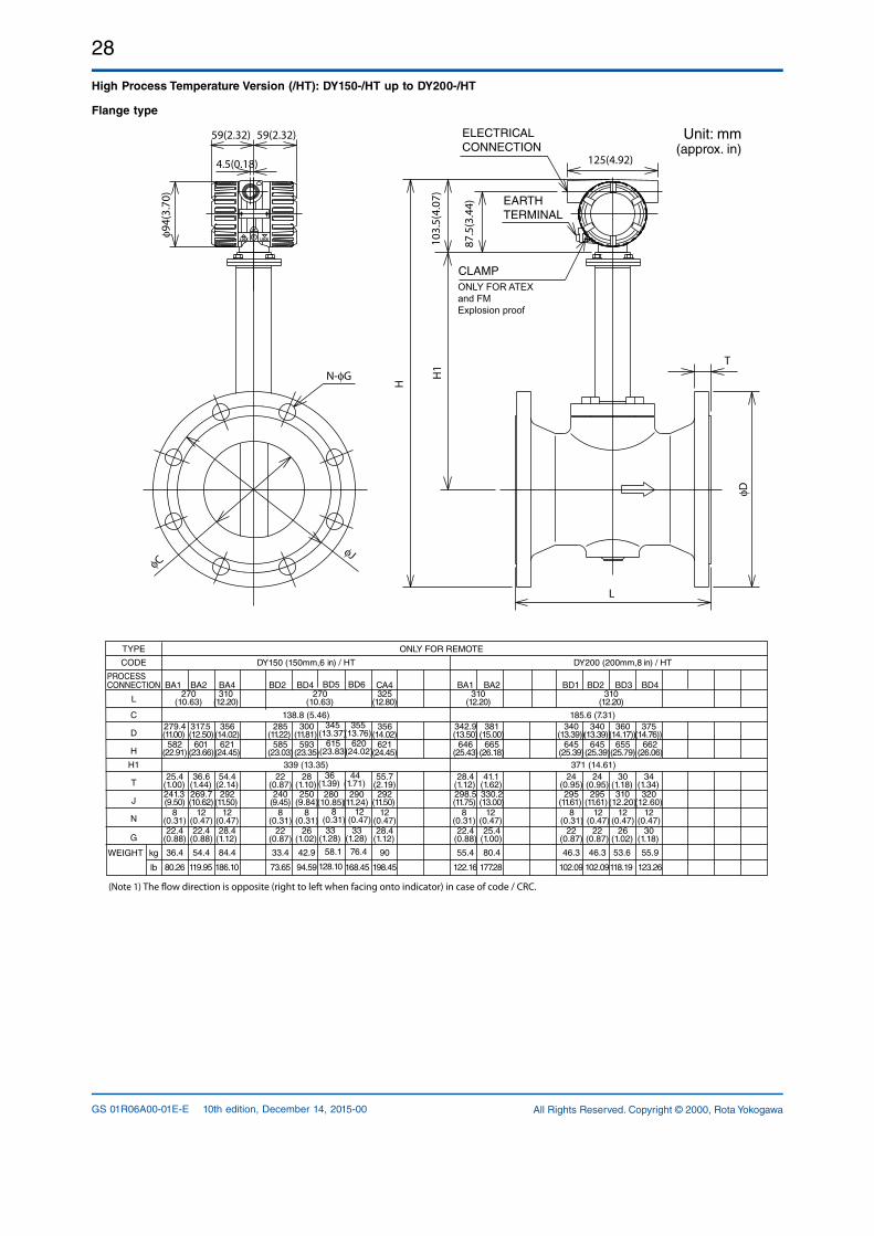
28
All Rights Reserved. Copyright © 2000, Rota YokogawaGS 01R06A00-01E-E 10th edition, December 14, 2015-00
High Process Temperature Version (/HT): DY150-/HT up to DY200-/HT
Flange type
Unit: mm(approx. in)
ELECTRICAL CONNECTION
CLAMP
N-φG
φCφJ
φD
H1
H
L
T
59(2.32) 59(2.32)
103.
5(4.
07)
87.5
(3.4
4)
φ94(
3.70
)125(4.92)4.5(0.18)
EARTH TERMINAL
ONLY FOR ATEXand FM Explosion proof
(Note 1) The ow direction is opposite (right to left when facing onto indicator) in case of code / CRC.
BA1 BA2 BA4 BA1 BA2
kg
lb
WEIGHT 55.953.646.342.933.4
22(0.87)
295(11.61)
24(0.95)
645(25.39)
340(13.39))
270(10.63)
356(14.02)
310(12.20)
DY200 (200mm,8 in) / HT
D
DY150 (150mm,6 in) / HT
L
C
H
H1
T
J
N
G
BD2 BD4 BD1 BD2 BD3 BD4270
(10.63)
138.8 (5.46)285
(11.22)300
(11.81)279.4(11.00)
317.5(12.50)
582(22.91)
601(23.66)
621(24.45)
585(23.03)
593(23.35)
339 (13.35)25.4
(1.00)36.6
(1.44)54.4
(2.14)22
(0.87)28
(1.10)240
(9.45)250
(9.84)241.3(9.50)
269.7(10.62)
292(11.50)
12(0.47)
12(0.47)
8(0.31)
8(0.31)
22.4(0.88)
22.4(0.88)
28.4(1.12)
22(0.87)
26(1.02)
8(0.31)
310(12.20)
310(12.20)
185.6 (7.31)342.9(13.50)
375(14.76))
381(15.00)
340(13.39))
360(14.17))
646(25.43)
665(26.18)
645(25.39)
655(25.79)
662(26.06)
371 (14.61)30
(1.18)28.4
(1.12)41.1
(1.62)24
(0.95)34
(1.34)298.5(11.75)
330.2(13.00)
295(11.61)
310(12.20)
320(12.60)
25.4(1.00)
22.4(0.88)
22(0.87)
26(1.02)
30(1.18)
36.4 54.4 84.4 55.4 80.4
ONLY FOR REMOTE
PROCESSCONNECTION
TYPE
CODE
28.4(1.12)
12(0.47)
292(11.50)
55.7(2.19)
621(24.45)
325(12.80)
CA4
356(14.02)
90
12(0.47)
8(0.31)
12(0.47)
12(0.47)
12(0.47)
8(0.31)
46.3
123.26118.19102.0994.5973.6580.26 119.95 186.10 122.16 177.28198.45 102.09
BD5 BD6
345(13.37)
355(13.76)
615(23.83)
620(24.02)
36(1.39)
44(1.71)
280(10.85)
290(11.24)
33(1.28)
58.1 76.4
8(0.31)
12(0.47)
128.10 168.45
33(1.28)
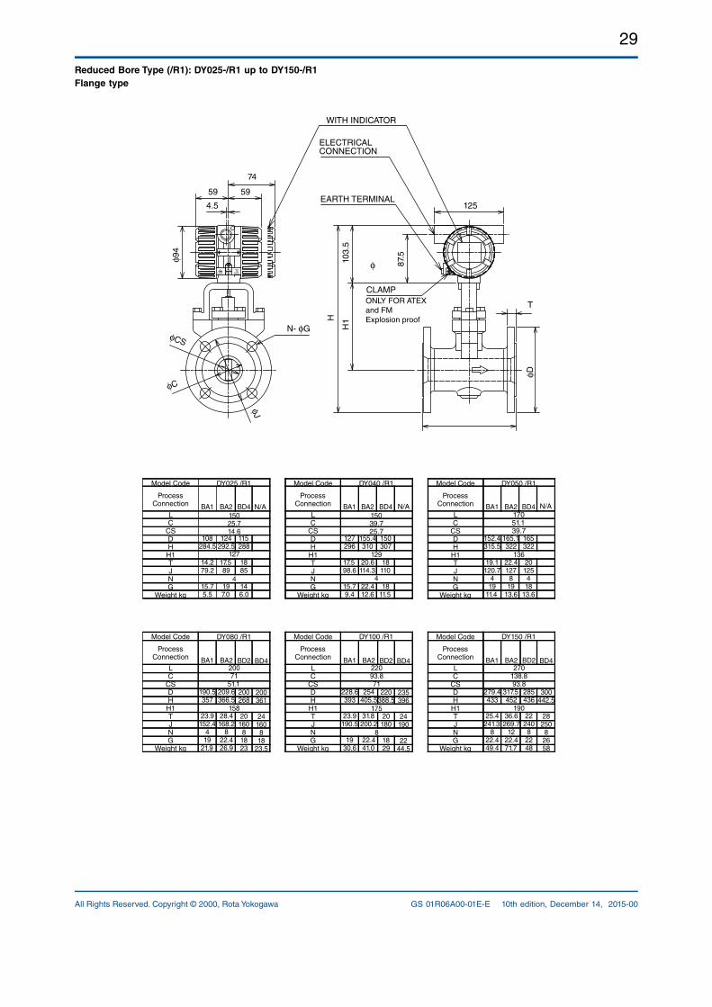
29
All Rights Reserved. Copyright © 2000, Rota Yokogawa GS 01R06A00-01E-E 10th edition, December 14, 2015-00
Reduced Bore Type (/R1): DY025-/R1 up to DY150-/R1Flange type
N- φG
φC
φCS
φJ
ELECTRICALCONNECTION
EARTH TERMINAL
WITH INDICATOR
87.5103.
5
CLAMP
H
H1
125
T
φD
59
74
59
4.5
φ94
ONLY FOR ATEXand FM Explosion proof
φ
15025.714.6
DY025 /R1
127
4
15039.725.7
129
4
BA1
108284.5
14.279.2
15.75.5
BA2
124292.5
17.589
197.0
DY040 /R1
BA1
127296
17.598.6
15.79.4
BA2
155.4310
20.6114.3
22.412.6
DY050 /R1
BA1
152.4315.5
19.1120.7
419
11.4
BA2
165.1322
22.4127
819
13.6
Model Code
Process Connection
LC
CSDHH1TJNG
Weight kg
Model Code
Process Connection
LC
CSDHH1TJNG
Weight kg
Model Code
Process Connection
LC
CSDHH1TJNG
Weight kg
136
17051.139.7
Model Code
Process Connection
LC
CSDHH1TJNG
Weight kg
Model Code
Process Connection
LC
CSDHH1TJNG
Weight kg
Model Code
Process Connection
LC
CSDHH1TJNG
Weight kg
DY080 /R1
BA1
190.5357
23.9152.4
419
21.9
BA2
209.6366.5
28.4168.2
822.426.9
DY100 /R1
BA1
228.6393
23.9190.5
1930.6
BA2
254405.5
31.8200.2
22.441.0
DY150 /R1
BA1
279.4433
25.4241.3
822.449.4
BA2
317.5452
36.6269.7
1222.471.7
20071
51.1
158 175 190
8
22093.871
270138.893.8
N/A N/A N/ABD4
115288
1885
146.0
BD4
150307
18110
1811.5
BD4
165322
20125
418
13.6
BD2
200268
20160
81823
BD4
200361
24160
818
23.5
BD2
220388.5
20180
1829
BD4
235396
24190
2244.5
BD2
285436
22240
82248
BD4
300442.5
28250
82658
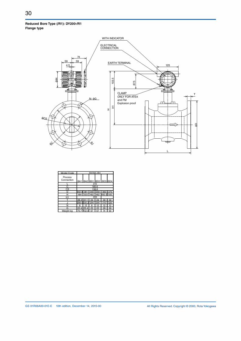
30
All Rights Reserved. Copyright © 2000, Rota YokogawaGS 01R06A00-01E-E 10th edition, December 14, 2015-00
Reduced Bore Type (/R1): DY200-/R1 Flange type
N- φG
φC
φCS
φJ
ELECTRICALCONNECTION
EARTH TERMINAL
WITH INDICATOR
87.510
3.5
CLAMP
H
H1
125
T
L
φD
59
74
59
4.5
φ94
Model Code
Process Connection
LC
CSDHH1TJNG
Weight kg
310185.6138.8
DY200 /R1
209
BA1
342.9484
28.4298.5
822.470.7
BA2
381503
41.1330.2
1225.4102.9
BD1
340482
24295
82267
BD2
340482
24295122267
BD3
360492.5
30310122674
BD4
375500
34320123090
ONLY FOR ATEXand FM Explosion proof
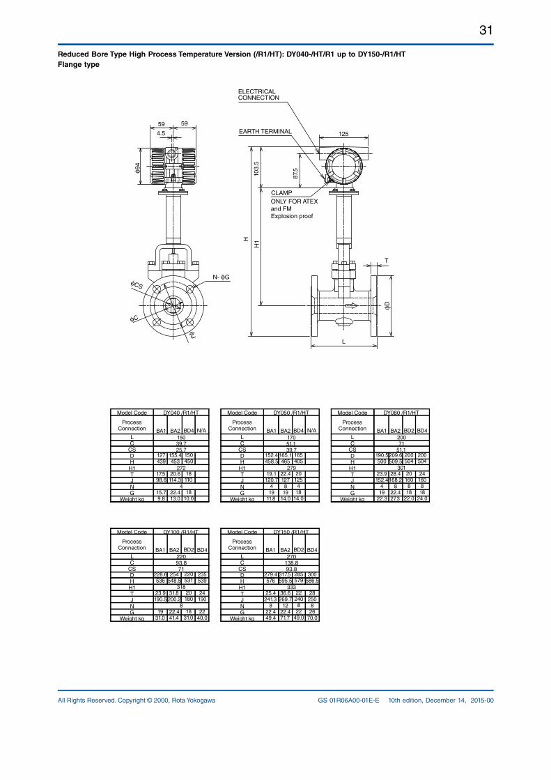
31
All Rights Reserved. Copyright © 2000, Rota Yokogawa GS 01R06A00-01E-E 10th edition, December 14, 2015-00
Reduced Bore Type High Process Temperature Version (/R1/HT): DY040-/HT/R1 up to DY150-/R1/HT Flange type
N- φG
φC
φCS
φJ
ELECTRICALCONNECTION
EARTH TERMINAL
87.5103.
5
CLAMP
H
H1
125
T
L
φ D
59 59
4.5φ9
4
DY040 /R1/HT
272
4
BA1
127439
17.598.6
15.79.8
BA2
155.4453
20.6114.3
22.413.0
DY050 /R1/HT
BA1
152.4458.5
19.1120.7
419
11.8
BA2
165.1465
22.4127
819
14.0
DY080 /R1/HT
BA1
190.5500
23.9152.4
419
22.3
BA2
209.6509.5
28.4168.2
822.427.3
279 301
17051.139.7
20071
51.1
15039.725.7
Model Code
Process Connection
LC
CSDHH1TJNG
Weight kg
Model Code
Process Connection
LC
CSDHH1TJNG
Weight kg
Model Code
Process Connection
LC
CSDHH1TJNG
Weight kg
Model Code
Process Connection
LC
CSDHH1TJNG
Weight kg
Model Code
Process Connection
LC
CSDHH1TJNG
Weight kg
DY100 /R1/HT
BA1
228.6536
23.9190.5
1931.0
BA2
254548.5
31.8200.2
22.441.4
DY150 /R1/HT
BA1
279.4576
25.4241.3
822.449.4
BA2
317.5595.5
36.6269.7
1222.471.7
22093.871
318
8
333
270138.893.8
N/A N/ABD4
150450
18110
1810.0
BD4
165405
20125
418
14.0
BD2
200504
20160
818
22.0
BD2
220531
20180
1831.0
BD4
235539
24190
2240.0
BD2
285579
22240
822
49.0
BD4
300586.5
28250
826
70.0
BD4
200504
24160
818
24.0
ONLY FOR ATEXand FM Explosion proof
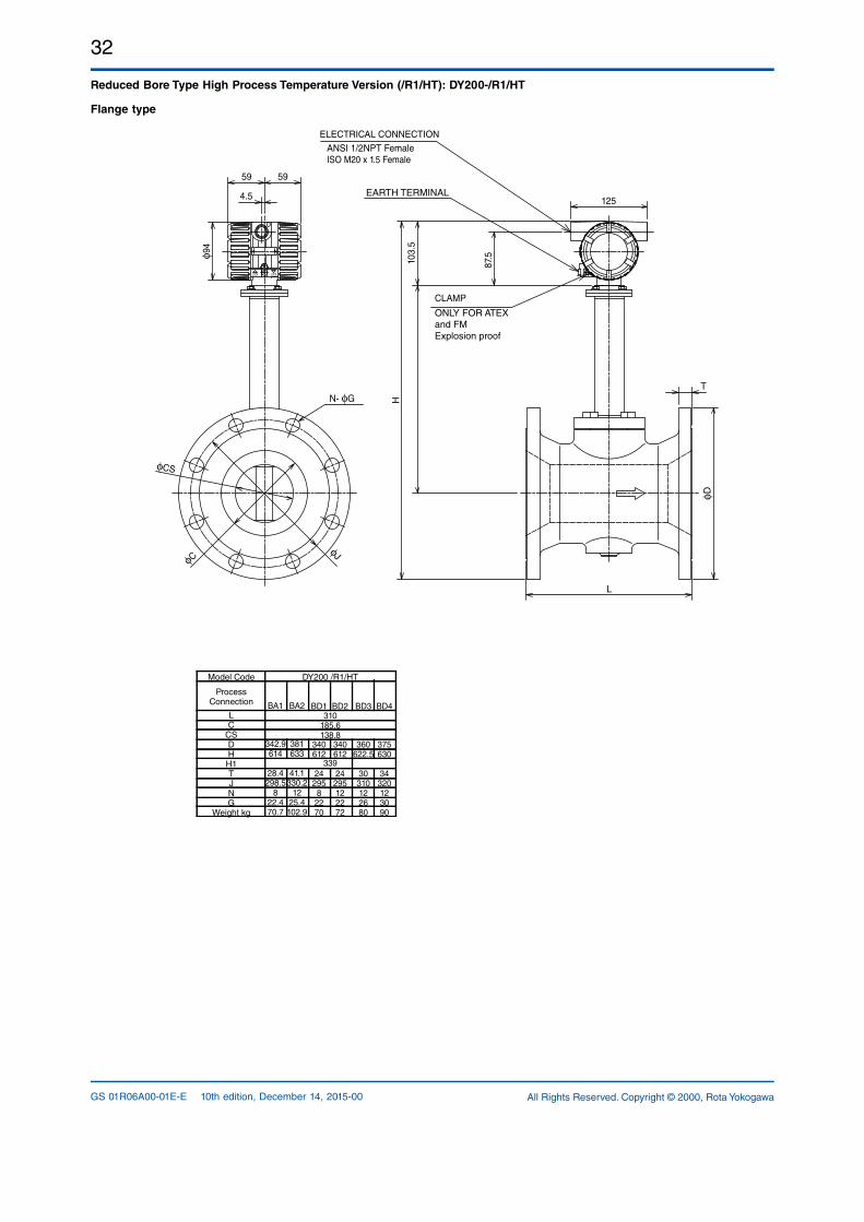
32
All Rights Reserved. Copyright © 2000, Rota YokogawaGS 01R06A00-01E-E 10th edition, December 14, 2015-00
Reduced Bore Type High Process Temperature Version (/R1/HT): DY200-/R1/HT
Flange type
φD
N- φG
φCS
φCφJ
125
87.510
3.5
T
L
H
φ94
4.5
59 59
ELECTRICAL CONNECTIONANSI 1/2NPT FemaleISO M20 x 1.5 Female
CLAMP
ONLY FOR ATEXand FM Explosion proof
EARTH TERMINAL
BA1
342.9614
28.4298.5
822.470.7
BA2
381633
41.1330.2
1225.4102.9
Model Code
Process Connection
LC
CSDHH1TJNG
Weight kg
310185.6138.8
DY200 /R1/HT
339
BD1
340612
24295
82270
BD2
340612
24295122272
BD3
360622.5
30310122680
BD4
375630
34320123090
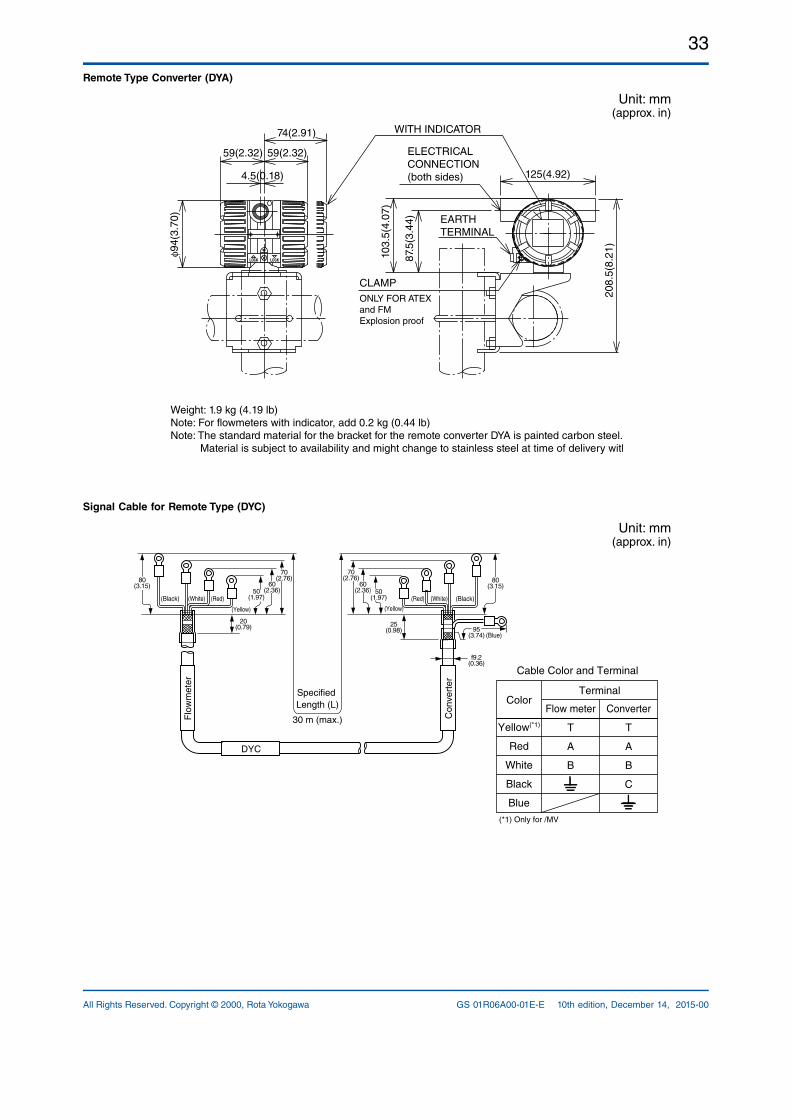
33
All Rights Reserved. Copyright © 2000, Rota Yokogawa GS 01R06A00-01E-E 10th edition, December 14, 2015-00
Remote Type Converter (DYA)
Unit: mm(approx. in)
Weight: 1.9 kg (4.19 lb)Note: For flowmeters with indicator, add 0.2 kg (0.44 lb)Note: The standard material for the bracket for the remote converter DYA is painted carbon steel. Material is subject to availability and might change to stainless steel at time of delivery without notice.
4.5(0.18)
59(2.32) 59(2.32)
125(4.92)
103.
5(4.
07)
74(2.91)
φ94(
3.70
)
208.
5(8.
21)
87.5
(3.4
4)
WITH INDICATOR
CLAMPONLY FOR ATEXand FM Explosion proof
ELECTRICAL CONNECTION(both sides)
EARTH TERMINAL
Signal Cable for Remote Type (DYC)
Unit: mm(approx. in)
(Black) (White) (Red) (Red) (White) (Black)
80(3.15)
70(2.76)
70(2.76) 80
(3.15)
f9.2(0.36)
(Blue)
60(2.36)
25(0.98) 95
(3.74)
60(2.36)50
(1.97)
20(0.79)
Specified Length (L)
30 m (max.)
DYC
Flo
wm
eter
Con
vert
er
Color
Cable Color and Terminal
Terminal
Yellow(*1)
Red
White
Black
Blue
Flow meter
T
A
B
Converter
T
A
B
C
(Yellow) (Yellow)
(*1) Only for /MV
50(1.97)
34
All Rights Reserved. Copyright © 2000, Rota YokogawaGS 01R06A00-01E-E 10th edition, December 14, 2015-00
ORDERING INSTRUCTIONS Specify the following when ordering :1. Model and suffix codes.2. Option code /MV: Select one of the six items below from [MULTIVARIABLE FUNCTION]. 1) Temperature monitoring/output 2) Saturated steam mass flowrate 3) Superheated steam mass flowrate 4) Gas volume flow rate 5) Liquid mass flow rate 6) Not use function3. Flow conditions a) Output Signal b) Communication c) Nominal Size (size of model code) d) Kind of Fluid e) Fluid Name f) Span, normal flow and minimum flow rates g) Maximum and normal operating temperatures h) Maximum and normal operating pressures i) Density at normal conditions j) Viscosity at normal conditions k) Deviation factor l) Totalized value rate m) Pulse rate
digitalYEWFLO Sizing Program is necessary to make a sizing data.
4. Tag Number
NOTE
If a tag number is specified upon ordering, the parameter “Tag No.” is set up before shipment; Up to 16 digits are programmable. The number programmed is then identical to the tag number on the data plate. If additionally to the tag number a software tag number was specified upon ordering the software tag number is the number that will be programmed in parameter “Tag No.”. The possible length for programming a software tag number depends on the communication code. DY[][][]D = BRAIN: up to 16 digits DY[][][]J = HART 5 : up to 8 digits DY[][][]J = HART 7 : up to 32 digits DY[][][]F = Foundation Fieldbus: up to 32 digits If value was not set to your requirements, it will be necessary for the appropriate value to be set by the user. Refer to GS 01F06F0001E for Fieldbus communication type.
= = = = = RELATED INSTRUMENTS = = = = =SDBT Distributor ................................See GS 1B4T1E See GS 1B4T2E= = = = = = RELATED MATERIAL = = = = = =Model DY Vortex Flowmeter TI 1F6A0001EModel DY Foundation Fieldbus GS 01F06F0101E
NOTE
GS 01R06A0001EE 10th edition is based on GS 01F06A0001E 23th edition.
YOKOGAWA ELECTRIC CORPORATIONHeadquarters2-9-32, Nakacho, Musashino-shi, Tokyo, 180-8750 JAPANPhone : 81-422-52-5555
Branch Sales OfficesOsaka, Nagoya, Hiroshima, Kurashiki, Fukuoka, Kitakyusyu
YOKOGAWA CORPORATION OF AMERICAHead Office12530 West Airport Blvd, Sugar Land, Texas 77478, USAPhone : 1-281-340-3800 Fax : 1-281-340-3838
Georgia Office2 Dart Road, Newnan, Georgia 30265, USA Phone : 1-800-888-6400/ 1-770-253-7000 Fax : 1-770-254-0928
YOKOGAWA AMERICA DO SUL LTDA.Praca Acapulco, 31 - Santo Amaro, Sáo Paulo/SP, BRAZIL, CEP-04675-190Phone : 55-11-5681-2400 Fax : 55-11-5681-4434
YOKOGAWA EUROPE B. V.Euroweg 2, 3825 HD Amersfoort, THE NETHERLANDSPhone : 31-88-4641000 Fax : 31-88-4641111
YOKOGAWA ELECTRIC CIS LTD.Grokholskiy per 13 Building 2, 4th Floor 129090, Moscow, RUSSIAPhone : 7-495-737-7868 Fax : 7-495-737-7869
YOKOGAWA CHINA CO., LTD.3F Tower D Cartelo Crocodile Building, No.568 West Tianshan Road, Shanghai 200335, CHINAPhone : 86-21-62396262 Fax : 86-21-62387866
YOKOGAWA ELECTRIC KOREA CO., LTD.(Yokogawa B/D, Yangpyeong-dong 4-Ga), 21, Seonyu-ro 45-gil, Yeongdeungpo-gu,Seoul, 150-866, KOREAPhone : 82-2-2628-6000 Fax : 82-2-2628-6400
YOKOGAWA ENGINEERING ASIA PTE. LTD.5 Bedok South Road, Singapore 469270, SINGAPOREPhone : 65-6241-9933 Fax : 65-6241-2606
YOKOGAWA INDIA LTD.Plot No.96, Electronic City Complex, Hosur Road, Bangalore - 560 100, INDIAPhone : 91-80-4158-6000 Fax : 91-80-2852-1442
YOKOGAWA AUSTRALIA PTY. LTD.Tower A, 112-118 Talavera Road, Macquarie Park NSW 2113, AUSTRALIAPhone : 61-2-8870-1100 Fax : 61-2-8870-1111
YOKOGAWA MIDDLE EAST & AFRICA B.S.C.(C)P.O. Box 10070, Manama, Building 577, Road 2516, Busaiteen 225, Muharraq,Kingdom of BAHRAINPhone : 973-17358100 Fax : 973-17336100 Apr. '15