Embed Size (px)
Citation preview

Published Manual Number: MTCEPB01• Specified Date: 20060823• As-of Date: 20060823• Access Date: 20060823• Custom: n/a• Applicability: CEP• Language Code: ENG01, Purpose: publication, Format: 1colA
General—Operating andTroubleshootingWasher-extractors withthe E-P OneTouch®
Controller
PELLERIN MILNOR CORPORATION POST OFFICE BOX 400, KENNER, LOUISIANA 70063 - 0400, U.S.A.

Applicable Milnor® products by model number:
MWR09E5- MWR18E4-
Preface
PELLERIN MILNOR CORPORATION
Preface
BICEUK01 (Published) Book specs- Dates: 20060823 / 20060823 / 20060823 Lang: ENG01 Applic: CEP
i. About This Manual
i. 1. ScopeThis manual provides commissioning, operating, and troubleshooting instructions for washer-extractors in the Milnor® MWR_ line. These machines are equipped with the Milnor® E-POneTouch® control. See the installation manual for information on machine installationprocedures and mechanical requirements. See the service manual for preventive maintenance,service procedures, and mechanical parts identification. See the schematic manual for electricalparts identification and electrical troubleshooting instructions.
Notice 1 : Milnor MWR_ models sold in North and South America employ the controllerboard with Milnor part number 08BT168AT. Similar models sold in Asia may employ controllerboard 08BT168AT or the controller board with Milnor part number 08BT168BT. Some minordifferences are determined by the market for which any particular machine is manufactured, butoperation and most troubleshooting procedures are the same. When necessary for clarity in thismanual, specific differences will be identified by the controller board part number.
i. 2. How to Identify this Manual and its Included Documents [DocumentBIUUUD13]A complete identification of this manual or any document in this manual must include allspecifications shown on the front cover, as defined below:Published manual number—Primary identification number for the manual or any variation of it.Specified date—The approximate date of introduction of the product or product change this
manual covers.As-of date—When a manual for an old product is generated, any new information about the old
product developed up to this date will be included in the manual.Access date—The date the manual was generated (assembled and formatted).Applicability—Code(s) that represent a group of machines this manual applies to and/or actual
model numbers of applicable machines. The complete list of applicable models is providedinside the front cover. If “not used” appears here, this is not a product manual, but has anotherpurpose such as to provide administrative procedures.
Language Code—A code representing the specific language and dialect of this manual. “Eng01”identifies the language/dialect of the manual as United States English.
When referring to any document used in this manual (as identified by an eight-characterdocument number such as BIUUUD13 at the start of the document), a complete identification ofthe document must include all specifications shown on the front cover, except substituting thedocument number for the published manual number.
Preface
PELLERIN MILNOR CORPORATION
i. 3. Trademarks [Document BIUUUD14]
i. 3.1. Trademarks of Pellerin Milnor Corporation—The following terms, some of whichmay be used in this publication, are trademarks of Pellerin Milnor Corporation:
Table 1: TrademarksCBW® E-P OneTouch® Mentor® Milnet® Staph-Guard®E-P Express® E-P Plus® Mildata® Milnor® Visionex™
Gear Guardian® MultiTrac™
i. 3.2. Trademarks of Other Companies—The following terms, some of which may be used inthis publication, are trademarks of their respective companies:
Table 2: Trademarks
Acronis® IBM® Microsoft OfficeXP® Microsoft Access® Siemens®
Atlas 2000® Microsoft Windows2000®
Microsoft WindowsNT®
Microsoft WindowsXP®
Seagate CrystalReports®
Yaskawa®
— End of BICEUK01 —
BIUUUK06 (Published) Book specs- Dates: 20060823 / 20060823 / 20060823 Lang: ENG01 Applic: CEP
ii. Contacting Milnor®Your first contact with any question should be your authorized Milnor dealer, but problems orspecial situations encountered in the field may require consultation with the Milnor factory.Written correspondence can be mailed to this address:
Pellerin Milnor CorporationPost Office Box 400Kenner, Louisiana 70063-0400Telephone: 504-467-9591http://www.milnor.com
ii. 1. Ordering Replacement PartsIn most cases your authorized Milnor dealer can provide any necessary parts for equipment youpurchased from them. If your dealer is not available or able to help you acquire parts, contact theMilnor parts group.
Milnor PartsTelephone: 504-467-2787Fax: 504-469-9777E-mail: [email protected]
ii. 2. Customer Service and Technical SupportFor your technical questions or comments about Milnor equipment, contact your Milnor dealerfirst. If your dealer is unable to respond, the Milnor customer service group has many years ofcollective experience with our equipment. These men and women will give you the best possibleanswer to your question.
Milnor Customer ServiceTelephone: 504-464-0163
Preface
PELLERIN MILNOR CORPORATION
Fax: 504-469-9777E-mail: [email protected] (Customer Service)
ii. 3. Warranty InformationYour Milnor dealer can address most warranty claims. However, if you have concerns orquestions beyond the scope of your dealer, please contact our warranty group.
Milnor Warranty AdministratorTelephone: 504-712-7735Fax: 504-469-9777E-mail: [email protected] (Attention: Warranty)
ii. 4. Equipment ManualsIf you have suggestions or questions about any part of this manual or any other documentationincluded with your machine, the Milnor technical publications group can assist you.
Milnor Technical PublicationsTelephone: 504-712-7636Fax: 504-469-1849E-mail: [email protected]
— End of BIUUUK06 —
Table of Contents
PELLERIN MILNOR CORPORATION
Table of ContentsSections Figures, Tables, and Supplements
Preface
i. About This Manual (Document BICEUK01)
i.1. Scopei.2. How to Identify this Manual and its Included Documents
(Document BIUUUD13)
i.3. Trademarks (Document BIUUUD14)
i.3.1. Trademarks of Pellerin Milnor Corporation Table 1: Trademarksi.3.2. Trademarks of Other Companies Table 2: Trademarks
ii. Contacting Milnor® (Document BIUUUK06)
ii.1. Ordering Replacement Partsii.2. Customer Service and Technical Supportii.3. Warranty Informationii.4. Equipment Manuals
Table of Contents
Chapter 1. Commissioning
1.1. Important Owner/User Information (Document BICEUK02)
1.1.1. Ensure Safety of All Laundry Personnel1.1.2. Customize the Machine Controller
1.2. About the Forces Transmitted by Washer-extractors(Document BIWUUI02)
1.2.1. Foundation Considerations1.2.2. How Strong and Rigid? Figure 1: How Rotating Forces Act on the
Foundation
1.3. Important Instructions for Pumped Chemical Inlets(Document BIWUUI01)
1.3.1. How Pumped Chemical Systems can Internally Damagethe Washer-extractor
Supplement 1: Preventing Dribbling byPurging Chemical Lines
1.3.2. Locating Chemical System Components to Reduce theRisk of Internal Damage
Figure 2: Proper Routing of ChemicalTubing
1.3.3. Preventing Leaks Which Can Injure Personnel and CauseExternal Damage
Figure 3: Rear-mounted Water and LiquidSupply Injector
1.4. Electrical Connections for Liquid Chemical Systems(Document BICEUI01)
Supplement 2: Maximizing ChemicalInjection Precision
1.4.1. Pump Signal Connections Table 3: Chemical Injection SignalsFigure 4: Pump Signal Connections
1.4.2. Timer Stop Connections Figure 5: Timer Stop Connections
Table of Contents
PELLERIN MILNOR CORPORATION
Sections Figures, Tables, and Supplements
1.5. Formulas in Milnor® Washer-extractors with E-POneTouch® Controls (Document BICEUP02)
1.5.1. Hotel and Hospitality Configuration (Document BICEUP03) Table 4: Bed and Bath Linen FormulasTable 5: Food and Beverage Service
Formulas1.5.2. Healthcare Configuration (Document BICEUP04) Table 6: Bed and Bath Linen Formulas
Table 7: Personal and Food/BeverageFormulas
Chapter 2. Configuring
2.1. Configuring E-P OneTouch® Washer-extractor Models(Document BICEUC01)
2.1.1. Is this switch position ON or OFF? Figure 6: Typical DIP switch on08BT168AT
Figure 7: Typical DIP switch on08BT168BT
2.1.2. Configuration Decisions for Machines with Controller08BT168AT
2.1.2.1. Position 1: Use Formula Set A?2.1.2.2. Position 2: Cold final rinse?2.1.2.3. Positions 3 through 6: not used2.1.2.4. Position 7: Normal operation?2.1.2.5. Position 8: Normal operation?2.1.3. Configuration Decisions for Machines with Controller
08BT168BTTable 8: Controller 08BT168BT:
Summary of Configuration Decisions2.1.3.1. Position 1: Configure for hospitality?2.1.3.2. Position 2: Use Bed and Bath Linen formulas?2.1.3.3. Position 3: Use cold water for the final rinse?2.1.3.4. Positions 4 and 5: Select desired hot bath temperature Table 9: Quick Reference for Hot Bath
Temperature2.1.3.5. Position 6: Use 140°F (60°C) for split bath
temperature?2.1.3.6. Position 7: Run bath timer while heating?2.1.3.7. Position 8: Set machine to normal operating mode?
Chapter 3. Operating
3.1. Determining Load Size (Document BIWUUO01)
3.2. Controls on E-P OneTouch® Model Washer-extractors(Document BICEUF01)
Figure 8: E-P OneTouch® Controls
3.2.1. Control Functions During Normal Operation3.2.1.1. Formula Selection Buttons3.2.1.2. Terminate Button
Table of Contents
PELLERIN MILNOR CORPORATION
Sections Figures, Tables, and Supplements
3.2.1.3. Last Rinse Light3.2.1.4. In Progress Light3.2.1.5. Door Unlock Button3.2.2. Control Functions During Testing3.2.2.1. Formula Selection Buttons3.2.2.1.1. Formula A button (")3.2.2.1.2. Formula B button (<)3.2.2.1.3. Formula C button (>)3.2.2.1.4. Formula D button (?)3.2.2.2. Terminate Button3.2.2.3. Last Rinse Light3.2.2.4. In Progress Light3.2.2.5. Door Unlock Button
3.3. E-P OneTouch® Operation (Document BICEUO01)
3.3.1. Instructions for Normal Operation3.3.1.1. Load the Machine3.3.1.2. Start a Formula3.3.1.2.1. After a Completed Formula (Normal)3.3.1.2.2. After Opening the Door during a Formula3.3.1.3. Unload the Machine3.3.2. How to End a Formula Early
Chapter 4. Testing and Troubleshooting
4.1. Troubleshooting Errors (Document BICEUT03)
4.1.1. Vibration Switch Tripped4.1.2. Door Open4.1.3. Door/Inverter Fault
4.2. Testing MWR_ Washer-extractors (Document BICEPT02)
4.2.1. Testing without the Display Kit Chart 1: Operating Sequence Part 1Chart 2: Operating Sequence Part 2Chart 3: Operating Sequence Part 3Chart 4: Operating Sequence Part 4
4.2.2. Testing with the Display Kit4.2.2.1. Connecting the Display Figure 9: Processor Boards4.2.2.2. Displays in Run Mode Chart 5: Overview of Run Mode
Diagnostics4.2.2.2.1. Timer Display4.2.2.2.2. DIP Switch Display4.2.2.2.3. Inputs Display Table 10: E-P OneTouch Inputs4.2.2.2.4. Outputs Display Table 11: E-P OneTouch Outputs4.2.2.2.5. Analog-to-Digital Channels Display
Table of Contents
PELLERIN MILNOR CORPORATION
Sections Figures, Tables, and Supplements
4.2.2.3. Displays in Test Mode4.2.2.3.1. Setting the DIP Switch for Test Mode Figure 10: Test Mode Selected4.2.2.3.2. Interpreting the Display4.2.2.3.3. DIP Switch Display4.2.2.3.4. Viewing Inputs
Figure 11: Level Switch Testing4.2.2.3.5. Testing Outputs
4.3. Event Timing for 08BT168AT Controller Boards(Document BICEUF02)
4.3.1. Hotel and Hospitality Software4.3.1.1. Formula Set 1 Table 12: Events for Hotel and Hospitality
Set 1, Formula ATable 13: Events for Hotel and Hospitality
Set 1, Formula BTable 14: Events for Hotel and Hospitality
Set 1, Formula CTable 15: Events for Hotel and Hospitality
Set 1, Formula D4.3.1.2. Formula Set 2 Table 16: Events for Hotel and Hospitality
Set 2, Formula ATable 17: Events for Hotel and Hospitality
Set 2, Formula BTable 18: Events for Hotel and Hospitality
Set 2, Formula CTable 19: Events for Hotel and Hospitality
Set 2, Formula D4.3.2. Healthcare Software4.3.2.1. Formula Set 1 Table 20: Events for Healthcare Set 1,
Formula ATable 21: Events for Healthcare Set 1,
Formula BTable 22: Events for Healthcare Set 1,
Formula CTable 23: Events for Healthcare Set 1,
Formula D4.3.2.2. Formula Set 2 Table 24: Events for Healthcare Set 2,
Formula ATable 25: Events for Healthcare Set 2,
Formula BTable 26: Events for Healthcare Set 2,
Formula CTable 27: Events for Healthcare Set 2,
Formula D
Table of Contents
PELLERIN MILNOR CORPORATION
Sections Figures, Tables, and Supplements
4.4. Event Timing for 08BT168BT Controller Boards(Document BICEUF03)
4.4.1. Hotel and Hospitality Software4.4.1.1. Formula Set 1 Table 28: Events for Hotel and Hospitality
Set 1, Formula ATable 29: Events for Hotel and Hospitality
Set 1, Formula BTable 30: Events for Hotel and Hospitality
Set 1, Formula CTable 31: Events for Hotel and Hospitality
Set 1, Formula D4.4.1.2. Formula Set 2 Table 32: Events for Hotel and Hospitality
Set 2, Formula ATable 33: Events for Hotel and Hospitality
Set 2, Formula BTable 34: Events for Hotel and Hospitality
Set 2, Formula CTable 35: Events for Hotel and Hospitality
Set 2, Formula D4.4.2. Healthcare Software4.4.2.1. Formula Set 1 Table 36: Events for Healthcare Set 1,
Formula ATable 37: Events for Healthcare Set 1,
Formula BTable 38: Events for Healthcare Set 1,
Formula CTable 39: Events for Healthcare Set 1,
Formula D4.4.2.2. Formula Set 2 Table 40: Events for Healthcare Set 2,
Formula ATable 41: Events for Healthcare Set 2,
Formula BTable 42: Events for Healthcare Set 2,
Formula CTable 43: Events for Healthcare Set 2,
Formula D
Chapter 1. Commissioning
PELLERIN MILNOR CORPORATION
Chapter 1Commissioning
BICEUK02 (Published) Book specs- Dates: 20060823 / 20060823 / 20060823 Lang: ENG01 Applic: CEP
1.1. Important Owner/User InformationThe following two procedures must be completed before this machine is placed in service:1. Ensure the safety of all laundry personnel.2. Customize the machine controller for the intended machine application.
1.1.1. Ensure Safety of All Laundry PersonnelEnsure that all personnel who will operate or maintain this machine read the safety manual beforepermitting them to access the machine. Ensure that all user manuals are available to theappropriate personnel and that all precautions explained in all applicable manuals are observed.
1.1.2. Customize the Machine ControllerCustomizing the controller includes verifying that it is configured for the particular application(set of four pre-programmed formulas) for which the machine will be used. Always verify themachine configuration when the machine is first placed in service and after replacing themicroprocessor controller.
Configure this machine by setting DIP switch SW1 on the microprocessor controller. See Section2.1. “Configuring E-P OneTouch® Washer-extractor Models” in this manual for the location ofdetailed configuration instructions.
— End of BICEUK02 —
BIWUUI02 (Published) Book specs- Dates: 20060823 / 20060823 / 20060823 Lang: ENG01 Applic: CEP
1.2. About the Forces Transmitted by Washer-extractorsDuring washing and extracting, all washer-extractors transmit both static and dynamic (cyclic)forces to the floor, foundation, or any other supporting structure. During washing, the impact ofthe goods as they drop imparts forces which are quite difficult to quantify. Size for size, bothrigid and flexibly-mounted machines transmit approximately the same forces during washing.During extracting, rigid machines transmit forces up to 30 times greater than equivalent flexibly-mounted models. The actual magnitude of these forces vary according to several factors:
• machine size,• final extraction speed,• amount, condition, and type of goods being processed,• the liquor level and chemical conditions in the bath preceding extraction, and• other miscellaneous factors.
Chapter 1. Commissioning
PELLERIN MILNOR CORPORATION
Estimates of the maximum force normally encountered are available for each model and sizeupon request. Floor or foundation sizes shown on any Milnor® document are only for on-gradesituations based only on previous experience without implying any warranty, obligation, orresponsibility on our part.
1.2.1. Foundation ConsiderationsSize for size, rigid washer-extractors naturally require a stronger, more rigid floor, foundation, orother supporting structure than flexibly-mounted models. If the supporting soil under the slab isitself strong and rigid enough and has not subsided to leave the floor slab suspended withoutsupport, on grade installations can often be made directly to an existing floor slab if it has enoughstrength and rigidity to safely withstand our published forces without transmitting unduevibration. If the subsoil has subsided, or if the floor slab itself has insufficient strength andrigidity, a deeper foundation, poured as to become monolithic with the floor slab, may berequired. Support pilings may even be required if the subsoil itself is “springy” (i.e., if itsresonant frequency is near the operating speed of the machine). Above-grade installations of rigidmachines also require a sufficiently strong and rigid floor or other supporting structure asdescribed below.
1.2.2. How Strong and Rigid?Many building codes in the U.S.A. specify that laundry floors must have a minimum live loadcapacity of 150 pounds per square foot (732 kilograms per square meter). However, evencompliance with this or any other standard does not necessarily guarantee sufficient rigidity. Inany event, it is the sole responsibility of the owner/user to assure that the floor and/or any othersupporting structure exceeds not only all applicable building codes, but also that the floor and/orany other supporting structure for each washer-extractor or group of washer-extractors actuallyhas sufficient strength and rigidity, plus a reasonable factor of safety for both, to support theweight of all the fully loaded machine(s) including the weight of the water and goods, andincluding the published 360-degree rotating sinusoidal RMS forces that are transmitted by themachine(s). Moreover, the floor, foundation, or other supporting structure must have sufficientrigidity (i.e., a natural or resonant frequency many times greater than the machine speed with areasonable factor of safety); otherwise, the mentioned 360-degree rotating sinusoidal RMS forcescan be multiplied and magnified many times. It is especially important to consider all potentialvibration problems that might occur due to all possible combinations of forcing frequencies(rotating speeds) of the machine(s) compared to the natural frequencies of the floor and/or anyother supporting structure(s). A qualified soil and/or structural engineer must be engaged for thispurpose.
Chapter 1. Commissioning
PELLERIN MILNOR CORPORATION
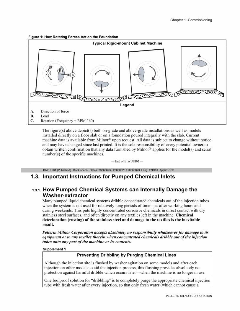
Figure 1: How Rotating Forces Act on the Foundation
Typical Rigid-mount Cabinet Machine
LegendA. Direction of forceB. LoadC. Rotation (Frequency = RPM / 60)
.
The figure(s) above depict(s) both on-grade and above-grade installations as well as modelsinstalled directly on a floor slab or on a foundation poured integrally with the slab. Currentmachine data is available from Milnor® upon request. All data is subject to change without noticeand may have changed since last printed. It is the sole responsibility of every potential owner toobtain written confirmation that any data furnished by Milnor® applies for the model(s) and serialnumber(s) of the specific machines.
— End of BIWUUI02 —
BIWUUI01 (Published) Book specs- Dates: 20060823 / 20060823 / 20060823 Lang: ENG01 Applic: CEP
1.3. Important Instructions for Pumped Chemical Inlets
1.3.1. How Pumped Chemical Systems can Internally Damage theWasher-extractorMany pumped liquid chemical systems dribble concentrated chemicals out of the injection tubeswhen the system is not used for relatively long periods of time—as after working hours andduring weekends. This puts highly concentrated corrosive chemicals in direct contact with drystainless steel surfaces, and often directly on any textiles left in the machine. Chemicaldeterioration (rusting) of the stainless steel and damage to the textiles is the inevitableresult.
Pellerin Milnor Corporation accepts absolutely no responsibility whatsoever for damage to itsequipment or to any textiles therein when concentrated chemicals dribble out of the injectiontubes onto any part of the machine or its contents.
Supplement 1
Preventing Dribbling by Purging Chemical Lines
Although the injection site is flushed by washer agitation on some models and after eachinjection on other models to aid the injection process, this flushing provides absolutely noprotection against harmful dribble which occurs later—when the machine is no longer in use.
One foolproof solution for “dribbling” is to completely purge the appropriate chemical injectiontube with fresh water after every injection, so that only fresh water (which cannot cause a
Chapter 1. Commissioning
PELLERIN MILNOR CORPORATION
problem) can dribble out.
Obviously, it is the sole responsibility of the pump and/or chemical supplier (not the machinemanufacturer) to furnish such a flushing device. (We understand that such flushing typechemical injection systems—both for retrofit to existing systems and for new installations—arenow offered by others.)
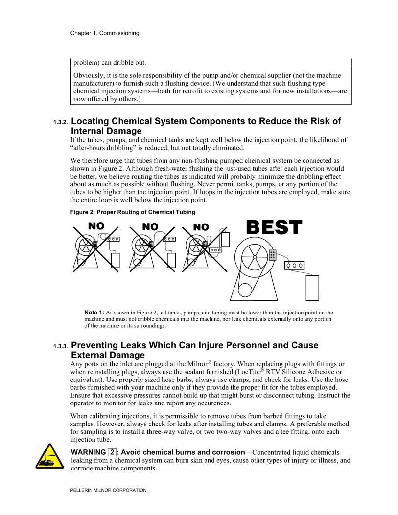
1.3.2. Locating Chemical System Components to Reduce the Risk ofInternal DamageIf the tubes, pumps, and chemical tanks are kept well below the injection point, the likelihood of“after-hours dribbling” is reduced, but not totally eliminated.
We therefore urge that tubes from any non-flushing pumped chemical system be connected asshown in Figure 2. Although fresh-water flushing the just-used tubes after each injection wouldbe better, we believe routing the tubes as indicated will probably minimize the dribbling effectabout as much as possible without flushing. Never permit tanks, pumps, or any portion of thetubes to be higher than the injection point. If loops in the injection tubes are employed, make surethe entire loop is well below the injection point.
Figure 2: Proper Routing of Chemical Tubing
Note 1: As shown in Figure 2, all tanks, pumps, and tubing must be lower than the injection point on themachine and must not dribble chemicals into the machine, nor leak chemicals externally onto any portionof the machine or its surroundings.
1.3.3. Preventing Leaks Which Can Injure Personnel and CauseExternal DamageAny ports on the inlet are plugged at the Milnor® factory. When replacing plugs with fittings orwhen reinstalling plugs, always use the sealant furnished (LocTite® RTV Silicone Adhesive orequivalent). Use properly sized hose barbs, always use clamps, and check for leaks. Use the hosebarbs furnished with your machine only if they provide the proper fit for the tubes employed.Ensure that excessive pressures cannot build up that might burst or disconnect tubing. Instruct theoperator to monitor for leaks and report any occurences.
When calibrating injections, it is permissible to remove tubes from barbed fittings to takesamples. However, always check for leaks after installing tubes and clamps. A preferable methodfor sampling is to install a three-way valve, or two two-way valves and a tee fitting, onto eachinjection tube.
WARNING 2 : Avoid chemical burns and corrosion—Concentrated liquid chemicalsleaking from a chemical system can burn skin and eyes, cause other types of injury or illness, andcorrode machine components.
Chapter 1. Commissioning
PELLERIN MILNOR CORPORATION
• Ensure that excessive pressures cannot build up which might burst or disconnect achemical delivery tube.
• Ensure that there are no external chemical leaks when the system is installed or calibrated.• Periodically check the system for leaks during operation.
CAUTION 3 : Avoid corrosion and textile damage—Chemicals dribbling into themachine when it is idle will corrode machine components and damage any textiles left in themachine.• If possible, use a system that flushes the entire chemical delivery tube after each injection.• If a non-flushing system is used, install tanks, pumps, and tubing below the injection point
on the machine, such that chemicals travel to the machine at an upward angle.
CAUTION 4 : Avoid explosions—Certain chemicals will react chemically when combined.Consult with your chemical supplier representative about the safe use of chemicals.• Connect chemical tubing so that bleach and sour inlets are as far apart as possible.
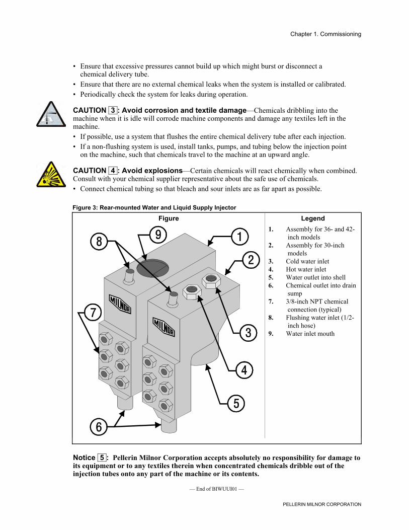
Figure 3: Rear-mounted Water and Liquid Supply Injector
Figure Legend
.
1. Assembly for 36- and 42-inch models
2. Assembly for 30-inchmodels
3. Cold water inlet4. Hot water inlet5. Water outlet into shell6. Chemical outlet into drain
sump7. 3/8-inch NPT chemical
connection (typical)8. Flushing water inlet (1/2-
inch hose)9. Water inlet mouth
Notice 5 : Pellerin Milnor Corporation accepts absolutely no responsibility for damage toits equipment or to any textiles therein when concentrated chemicals dribble out of theinjection tubes onto any part of the machine or its contents.
— End of BIWUUI01 —
Chapter 1. Commissioning
PELLERIN MILNOR CORPORATION
BICEUI01 (Published) Book specs- Dates: 20060823 / 20060823 / 20060823 Lang: ENG01 Applic: CEP
1.4. Electrical Connections for Liquid Chemical SystemsWARNING 6 : Electric Shock Hazard—Contact with high voltage electricity will kill orseriously injure you. Even when the machine is not running, three-phase power and controlcircuit power are still present at several locations within the cabinet and at some electricalcomponents.
CAUTION 7 : Injury and Damage Hazards—Improper wiring can cause the machine tomalfunction, risking injury to personnel, damage to machine components, and damage to goods.• Electrical and piping connections described in this section must be made only by
qualified, authorized personnel.• Lock off and tag out power at the external disconnect switches for the washer-extractor
before proceeding.• Do not rely merely on the information in this section when wiring. Consult all applicable
electrical schematics.• Do not reroute or rearrange any wires not specifically permitted by this instruction.• Do not connect a common wire to ground. Use the common terminal furnished.
CAUTION 8 : Risk of Poor or Inconsistent Wash Quality—Injection times of less than10 seconds are discouraged because fine adjustments are not possible, and factors such as pumplag time may cause significant variations in the amount of chemical delivered.• Size pumps or valves small enough for adequate control (i.e., for longer injection times).• Use two pumps or valves to inject a small or large quantity of the same chemical, if
required.
Supplement 2
Maximizing Chemical Injection Precision
Injection of a consistent amount of chemical is important in controlling wash quality and usingchemicals economically. When chemicals are injected by units of time, as is done with mostwasher-extractors, injections of short duration can be imprecise because of two reasons:
• Fine adjustments to the delivered quantity are not possible. For example, if an injection ofthree seconds is extended by one second, the quantity delivered is theoretically increased bymore than 30 percent. However, if an injection of 20 seconds is increased by one second,the theoretical quantity is increased by only five percent.
• Variations in the time between the start of the chemical signal and the start of the chemicaldelivery into the machine can cause significant differences in the quantity of chemicalinjected. In this case, if a pump starts more slowly some times than others, or if the deliverytubes are partially empty at the start of the inject period, the quantity of chemical deliveredmay vary significantly. As an example, assume a peristaltic pump moves chemical alongthe delivery tube at a rate of three feet per second. If the delivery tube is empty for threefeet along its length, then one second of the injection time is spent injecting air rather thanchemical. If the programmed injection time is only three seconds, then one third of thedesired chemical is not being delivered. However, if the programmed injection time is 20seconds, the chemical delivery is only five percent less than desired.
Chapter 1. Commissioning
PELLERIN MILNOR CORPORATION
Increasing the programmed injection time makes any variation less significant. Use pumpsand/or valves sized to allow inject times of at least 10 seconds. If injection times for a specificchemical vary widely from one formula to another, consider using two pumps or valves for thesame chemical. Actuate one pump for injecting small quantities, and use both pumps or valvesfor larger quantities.
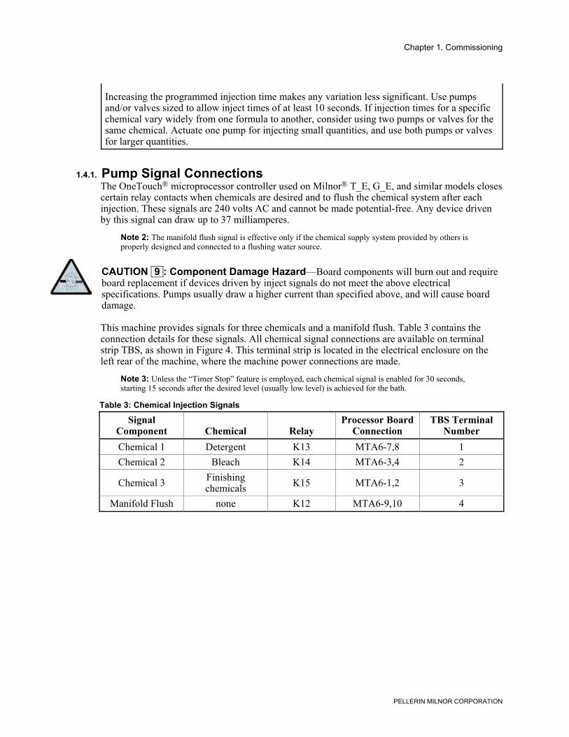
1.4.1. Pump Signal ConnectionsThe OneTouch® microprocessor controller used on Milnor® T_E, G_E, and similar models closescertain relay contacts when chemicals are desired and to flush the chemical system after eachinjection. These signals are 240 volts AC and cannot be made potential-free. Any device drivenby this signal can draw up to 37 milliamperes.
Note 2: The manifold flush signal is effective only if the chemical supply system provided by others isproperly designed and connected to a flushing water source.
CAUTION 9 : Component Damage Hazard—Board components will burn out and requireboard replacement if devices driven by inject signals do not meet the above electricalspecifications. Pumps usually draw a higher current than specified above, and will cause boarddamage.
This machine provides signals for three chemicals and a manifold flush. Table 3 contains theconnection details for these signals. All chemical signal connections are available on terminalstrip TBS, as shown in Figure 4. This terminal strip is located in the electrical enclosure on theleft rear of the machine, where the machine power connections are made.
Note 3: Unless the “Timer Stop” feature is employed, each chemical signal is enabled for 30 seconds,starting 15 seconds after the desired level (usually low level) is achieved for the bath.
Table 3: Chemical Injection Signals
SignalComponent Chemical Relay
Processor BoardConnection
TBS TerminalNumber
Chemical 1 Detergent K13 MTA6-7,8 1Chemical 2 Bleach K14 MTA6-3,4 2
Chemical 3 Finishingchemicals K15 MTA6-1,2 3
Manifold Flush none K12 MTA6-9,10 4
Chapter 1. Commissioning
PELLERIN MILNOR CORPORATION
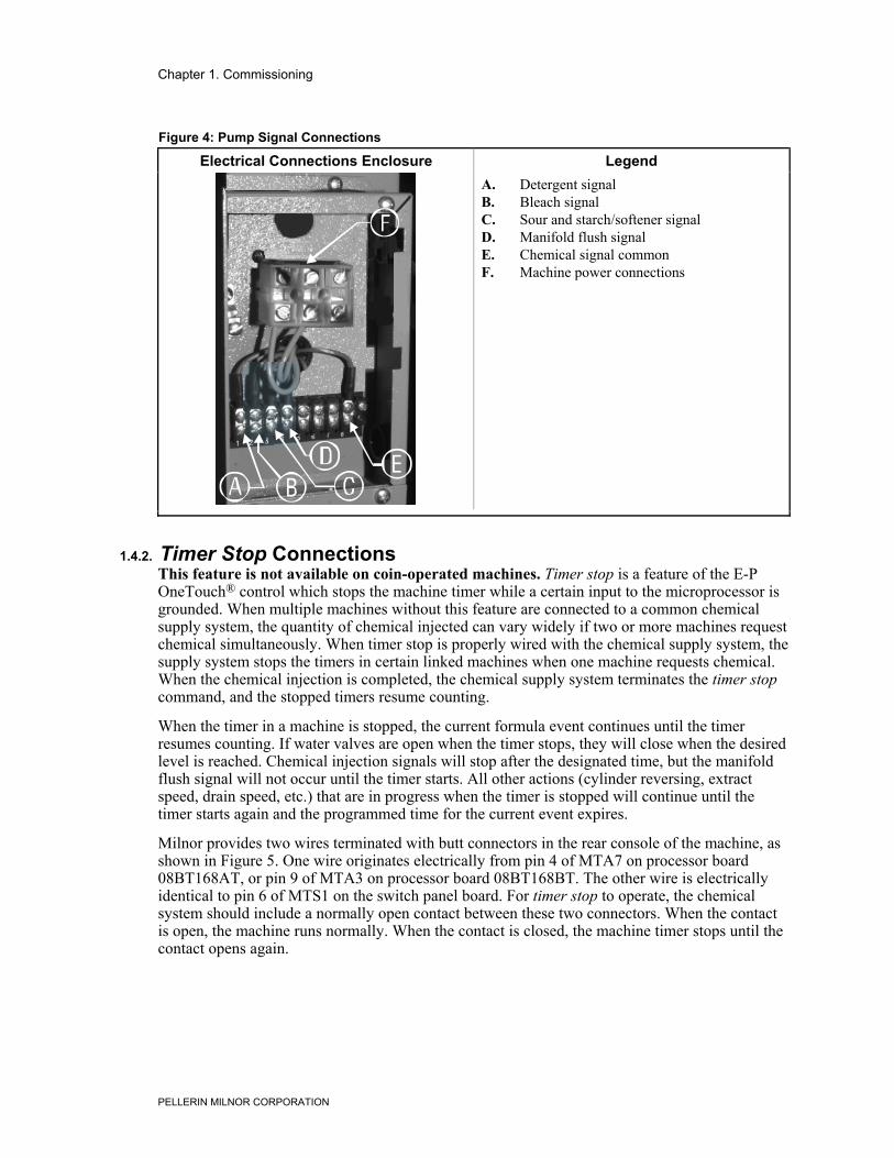
Figure 4: Pump Signal Connections
Electrical Connections Enclosure Legend
.
A. Detergent signalB. Bleach signalC. Sour and starch/softener signalD. Manifold flush signalE. Chemical signal commonF. Machine power connections
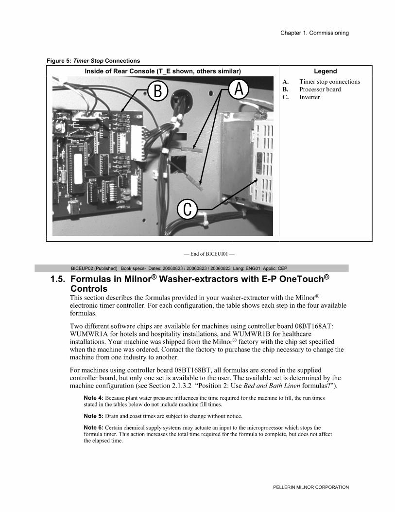
1.4.2. Timer Stop ConnectionsThis feature is not available on coin-operated machines. Timer stop is a feature of the E-POneTouch® control which stops the machine timer while a certain input to the microprocessor isgrounded. When multiple machines without this feature are connected to a common chemicalsupply system, the quantity of chemical injected can vary widely if two or more machines requestchemical simultaneously. When timer stop is properly wired with the chemical supply system, thesupply system stops the timers in certain linked machines when one machine requests chemical.When the chemical injection is completed, the chemical supply system terminates the timer stopcommand, and the stopped timers resume counting.
When the timer in a machine is stopped, the current formula event continues until the timerresumes counting. If water valves are open when the timer stops, they will close when the desiredlevel is reached. Chemical injection signals will stop after the designated time, but the manifoldflush signal will not occur until the timer starts. All other actions (cylinder reversing, extractspeed, drain speed, etc.) that are in progress when the timer is stopped will continue until thetimer starts again and the programmed time for the current event expires.
Milnor provides two wires terminated with butt connectors in the rear console of the machine, asshown in Figure 5. One wire originates electrically from pin 4 of MTA7 on processor board08BT168AT, or pin 9 of MTA3 on processor board 08BT168BT. The other wire is electricallyidentical to pin 6 of MTS1 on the switch panel board. For timer stop to operate, the chemicalsystem should include a normally open contact between these two connectors. When the contactis open, the machine runs normally. When the contact is closed, the machine timer stops until thecontact opens again.
Chapter 1. Commissioning
PELLERIN MILNOR CORPORATION
Figure 5: Timer Stop Connections
Inside of Rear Console (T_E shown, others similar) Legend
.
A. Timer stop connectionsB. Processor boardC. Inverter
— End of BICEUI01 —
BICEUP02 (Published) Book specs- Dates: 20060823 / 20060823 / 20060823 Lang: ENG01 Applic: CEP
1.5. Formulas in Milnor® Washer-extractors with E-P OneTouch®ControlsThis section describes the formulas provided in your washer-extractor with the Milnor®
electronic timer controller. For each configuration, the table shows each step in the four availableformulas.
Two different software chips are available for machines using controller board 08BT168AT:WUMWR1A for hotels and hospitality installations, and WUMWR1B for healthcareinstallations. Your machine was shipped from the Milnor® factory with the chip set specifiedwhen the machine was ordered. Contact the factory to purchase the chip necessary to change themachine from one industry to another.
For machines using controller board 08BT168BT, all formulas are stored in the suppliedcontroller board, but only one set is available to the user. The available set is determined by themachine configuration (see Section 2.1.3.2 “Position 2: Use Bed and Bath Linen formulas?”).
Note 4: Because plant water pressure influences the time required for the machine to fill, the run timesstated in the tables below do not include machine fill times.
Note 5: Drain and coast times are subject to change without notice.
Note 6: Certain chemical supply systems may actuate an input to the microprocessor which stops theformula timer. This action increases the total time required for the formula to complete, but does not affectthe elapsed time.
Chapter 1. Commissioning
PELLERIN MILNOR CORPORATION
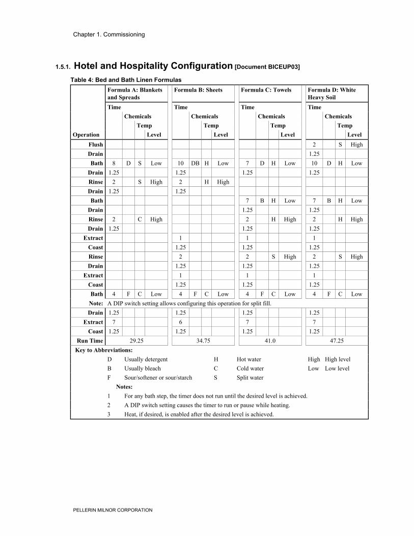
1.5.1. Hotel and Hospitality Configuration [Document BICEUP03]
Table 4: Bed and Bath Linen FormulasFormula A: Blanketsand Spreads
Formula B: Sheets Formula C: Towels Formula D: WhiteHeavy Soil
Time Time Time TimeChemicals Chemicals Chemicals Chemicals
Temp Temp Temp TempOperation Level Level Level Level
Flush 2 S HighDrain 1.25Bath 8 D S Low 10 DB H Low 7 D H Low 10 D H Low
Drain 1.25 1.25 1.25 1.25Rinse 2 S High 2 H HighDrain 1.25 1.25Bath 7 B H Low 7 B H Low
Drain 1.25 1.25Rinse 2 C High 2 H High 2 H HighDrain 1.25 1.25 1.25
Extract 1 1 1Coast 1.25 1.25 1.25Rinse 2 2 S High 2 S HighDrain 1.25 1.25 1.25
Extract 1 1 1Coast 1.25 1.25 1.25Bath 4 F C Low 4 F C Low 4 F C Low 4 F C Low
Note: A DIP switch setting allows configuring this operation for split fill.Drain 1.25 1.25 1.25 1.25
Extract 7 6 7 7Coast 1.25 1.25 1.25 1.25
Run Time 29.25 34.75 41.0 47.25Key to Abbreviations:
D Usually detergent H Hot water High High levelB Usually bleach C Cold water Low Low levelF Sour/softener or sour/starch S Split water
Notes:1 For any bath step, the timer does not run until the desired level is achieved.2 A DIP switch setting causes the timer to run or pause while heating.3 Heat, if desired, is enabled after the desired level is achieved.
Chapter 1. Commissioning
PELLERIN MILNOR CORPORATION
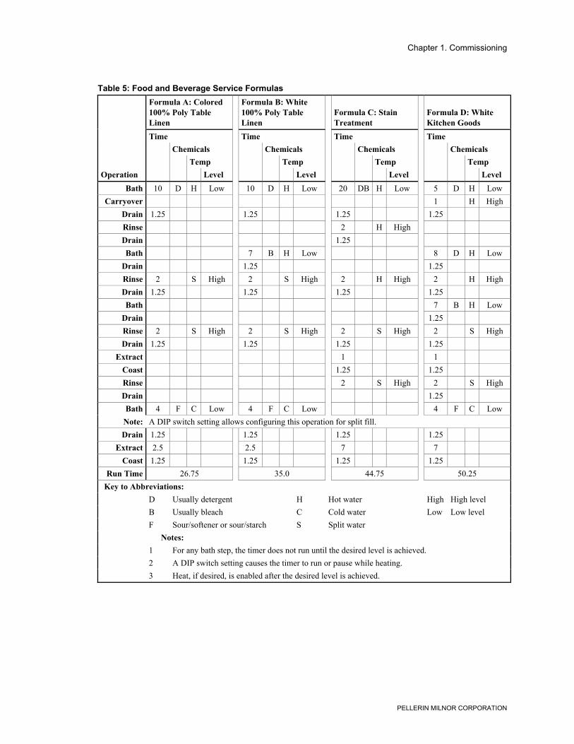
Table 5: Food and Beverage Service FormulasFormula A: Colored100% Poly TableLinen
Formula B: White100% Poly TableLinen
Formula C: StainTreatment
Formula D: WhiteKitchen Goods
Time Time Time TimeChemicals Chemicals Chemicals Chemicals
Temp Temp Temp TempOperation Level Level Level Level
Bath 10 D H Low 10 D H Low 20 DB H Low 5 D H LowCarryover 1 H High
Drain 1.25 1.25 1.25 1.25Rinse 2 H HighDrain 1.25Bath 7 B H Low 8 D H Low
Drain 1.25 1.25Rinse 2 S High 2 S High 2 H High 2 H HighDrain 1.25 1.25 1.25 1.25Bath 7 B H Low
Drain 1.25Rinse 2 S High 2 S High 2 S High 2 S HighDrain 1.25 1.25 1.25 1.25
Extract 1 1Coast 1.25 1.25Rinse 2 S High 2 S HighDrain 1.25Bath 4 F C Low 4 F C Low 4 F C Low
Note: A DIP switch setting allows configuring this operation for split fill.Drain 1.25 1.25 1.25 1.25
Extract 2.5 2.5 7 7Coast 1.25 1.25 1.25 1.25
Run Time 26.75 35.0 44.75 50.25Key to Abbreviations:
D Usually detergent H Hot water High High levelB Usually bleach C Cold water Low Low levelF Sour/softener or sour/starch S Split water
Notes:1 For any bath step, the timer does not run until the desired level is achieved.2 A DIP switch setting causes the timer to run or pause while heating.3 Heat, if desired, is enabled after the desired level is achieved.
Chapter 1. Commissioning
PELLERIN MILNOR CORPORATION
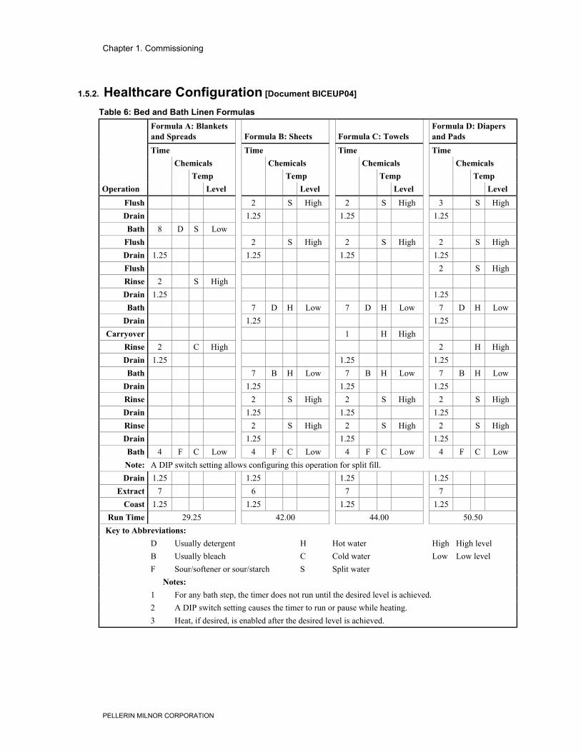
1.5.2. Healthcare Configuration [Document BICEUP04]
Table 6: Bed and Bath Linen FormulasFormula A: Blanketsand Spreads Formula B: Sheets Formula C: Towels
Formula D: Diapersand Pads
Time Time Time TimeChemicals Chemicals Chemicals Chemicals
Temp Temp Temp TempOperation Level Level Level Level
Flush 2 S High 2 S High 3 S HighDrain 1.25 1.25 1.25Bath 8 D S Low
Flush 2 S High 2 S High 2 S HighDrain 1.25 1.25 1.25 1.25Flush 2 S HighRinse 2 S HighDrain 1.25 1.25Bath 7 D H Low 7 D H Low 7 D H Low
Drain 1.25 1.25Carryover 1 H High
Rinse 2 C High 2 H HighDrain 1.25 1.25 1.25Bath 7 B H Low 7 B H Low 7 B H Low
Drain 1.25 1.25 1.25Rinse 2 S High 2 S High 2 S HighDrain 1.25 1.25 1.25Rinse 2 S High 2 S High 2 S HighDrain 1.25 1.25 1.25Bath 4 F C Low 4 F C Low 4 F C Low 4 F C Low
Note: A DIP switch setting allows configuring this operation for split fill.Drain 1.25 1.25 1.25 1.25
Extract 7 6 7 7Coast 1.25 1.25 1.25 1.25
Run Time 29.25 42.00 44.00 50.50Key to Abbreviations:
D Usually detergent H Hot water High High levelB Usually bleach C Cold water Low Low levelF Sour/softener or sour/starch S Split water
Notes:1 For any bath step, the timer does not run until the desired level is achieved.2 A DIP switch setting causes the timer to run or pause while heating.3 Heat, if desired, is enabled after the desired level is achieved.
Chapter 1. Commissioning
PELLERIN MILNOR CORPORATION
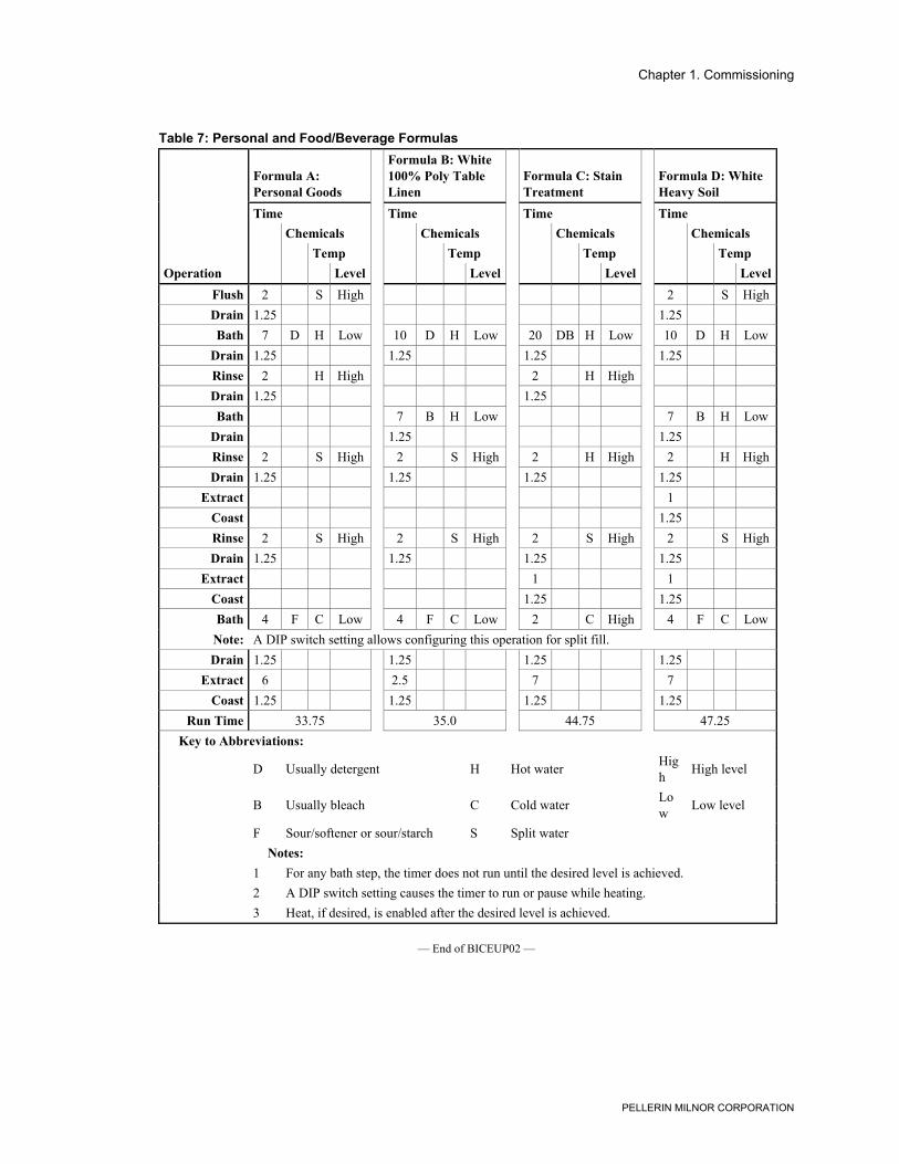
Table 7: Personal and Food/Beverage Formulas
Formula A:Personal Goods
Formula B: White100% Poly TableLinen
Formula C: StainTreatment
Formula D: WhiteHeavy Soil
Time Time Time TimeChemicals Chemicals Chemicals Chemicals
Temp Temp Temp TempOperation Level Level Level Level
Flush 2 S High 2 S HighDrain 1.25 1.25Bath 7 D H Low 10 D H Low 20 DB H Low 10 D H Low
Drain 1.25 1.25 1.25 1.25Rinse 2 H High 2 H HighDrain 1.25 1.25Bath 7 B H Low 7 B H Low
Drain 1.25 1.25Rinse 2 S High 2 S High 2 H High 2 H HighDrain 1.25 1.25 1.25 1.25
Extract 1Coast 1.25Rinse 2 S High 2 S High 2 S High 2 S HighDrain 1.25 1.25 1.25 1.25
Extract 1 1Coast 1.25 1.25Bath 4 F C Low 4 F C Low 2 C High 4 F C Low
Note: A DIP switch setting allows configuring this operation for split fill.Drain 1.25 1.25 1.25 1.25
Extract 6 2.5 7 7Coast 1.25 1.25 1.25 1.25
Run Time 33.75 35.0 44.75 47.25Key to Abbreviations:
D Usually detergent H Hot water High High level
B Usually bleach C Cold water Low Low level
F Sour/softener or sour/starch S Split waterNotes:
1 For any bath step, the timer does not run until the desired level is achieved.2 A DIP switch setting causes the timer to run or pause while heating.3 Heat, if desired, is enabled after the desired level is achieved.
— End of BICEUP02 —
Chapter 2. Configuring
PELLERIN MILNOR CORPORATION
Chapter 2Configuring
BICEUC01 (Published) Book specs- Dates: 20060823 / 20060823 / 20060823 Lang: ENG01 Applic: CEP
2.1. Configuring E-P OneTouch® Washer-extractor ModelsThe controller must be configured for your specific machine. Configuration information iscontrolled by a group of small switches (together called a DIP switch) on the processor board.When power is first applied to the machine, the microprocessor reads the on or off status of eachswitch.
2.1.1. Is this switch position ON or OFF?You can set any DIP switch position to on or off. To turn a position off, you must either pressdown on the side of the switch nearest the word “OFF,” or slide the handle toward the positionnumber. To turn a position “on,” you either press down on the side of the switch nearest thenumber, or slide the white handle toward the word “ON.” Use a pencil or a stiff wire to set theswitch, which will click into either position. See Figure 6 or Figure 7 for the DIP switch location.
Tip: Some switch positions are not used on machines equipped with controller board 08BT168AT.See Notice 1 in Section i.1.
Chapter 2. Configuring
PELLERIN MILNOR CORPORATION
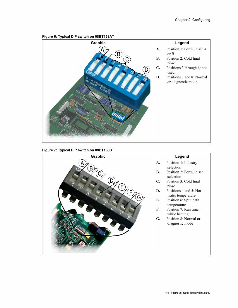
Figure 6: Typical DIP switch on 08BT168AT
Graphic Legend
.
A. Position 1: Formula set Aor B
B. Position 2: Cold finalrinse
C. Positions 3 through 6: notused
D. Positions 7 and 8: Normalor diagnostic mode
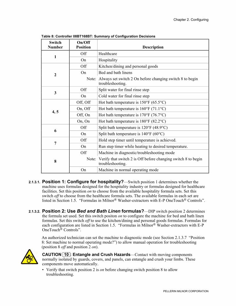
Figure 7: Typical DIP switch on 08BT168BT
Graphic Legend
.
A. Position 1: Industryselection
B. Position 2: Formula setselection
C. Position 3: Cold finalrinse
D. Positions 4 and 5: Hotwater temperature
E. Position 6: Split bathtemperature
F. Position 7: Run timerwhile heating
G. Position 8: Normal ordiagnostic mode

Chapter 2. Configuring
PELLERIN MILNOR CORPORATION
2.1.2. Configuration Decisions for Machines with Controller08BT168AT
2.1.2.1. Position 1: Use Formula Set A?—DIP switch position 1 determines the formula setused. Set this switch position on to configure the machine for the four primary formulas (Set A),which are designed primarily for bed and bath linen. Set this switch off to use the alternate set offormulas (Set B, primarily for kitchen/dining and personal goods). The formulas are listed inSection 1.5. “Formulas in Milnor® Washer-extractors with E-P OneTouch® Controls”.
2.1.2.2. Position 2: Cold final rinse?—In some locations the temperature of the incoming coldwater may be too cold to allow the proper activation of some chemicals. In these locations, turnswitch position 2 off to cause both water valves to open for all sour/softener steps.
2.1.2.3. Positions 3 through 6: not used—DIP switch positions 3, 4, 5, and 6 are not used inthese machine models comprising controller board 08BT168AT. These positions have no effecton the operation of the machine.
2.1.2.4. Position 7: Normal operation?—The Milnor factory sets switch position 7 off whenpreparing and testing the board before installation. Set this switch position on before firstcommissioning the machine, or before installing a replacement board. The machine will notenter the diagnostics mode if this position is on.
2.1.2.5. Position 8: Normal operation?—Switch position 8 determines whether the machine isconfigured for normal operation or for diagnostics. With this position on, the machine operatesnormally by running formulas. Verify that this switch position is on before firstcommissioning the machine, or before installing a replacement board.
When switch position 8 is off, the machine is configured for diagnostics. In this configuration, anoptional display can be connected to the processor board to aid in diagnosing problems when aqualified technician manually actuates individual outputs.
2.1.3. Configuration Decisions for Machines with Controller08BT168BTUsually, each switch represents a configuration decision with two possible answers. Thedecisions and the result of each answer are described below.
Tip: In most cases, the answer to the configure decision is either yes or no. To answer yes, set thecorresponding DIP switch to the on position by sliding the switch handle to the ON position. Toanswer no, set the switch toward the position number.
Chapter 2. Configuring
PELLERIN MILNOR CORPORATION
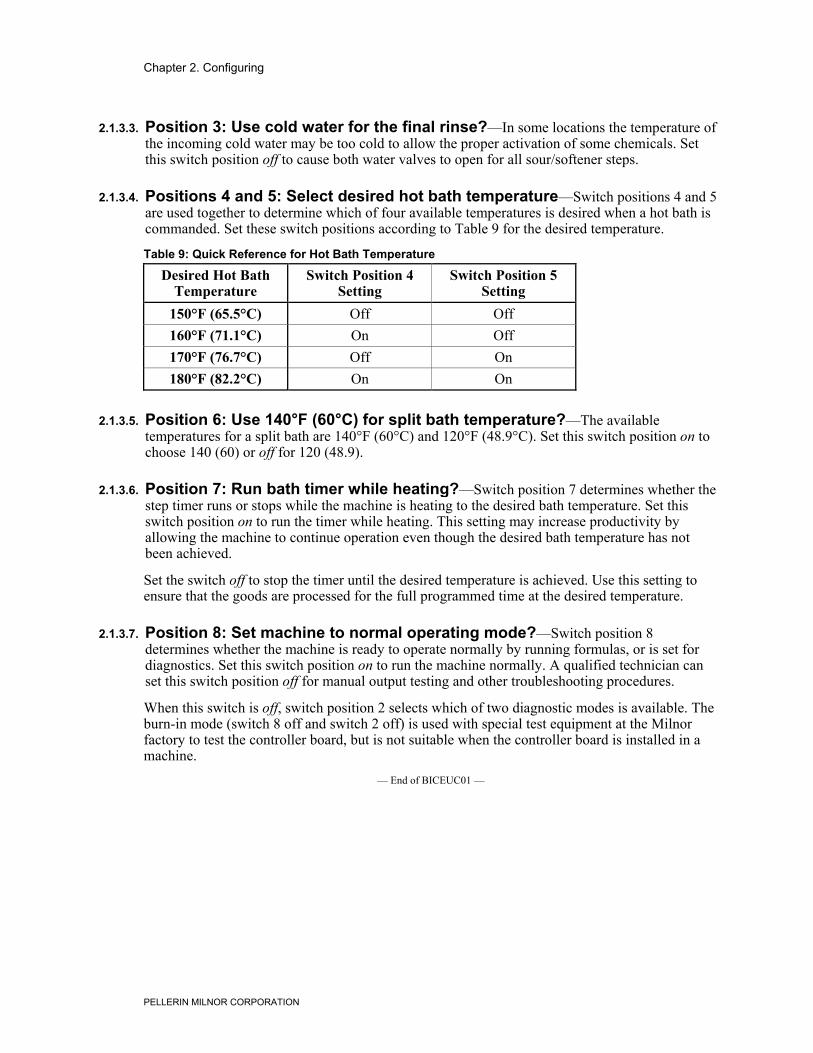
Table 8: Controller 08BT168BT: Summary of Configuration Decisions
SwitchNumber
On/OffPosition Description
Off Healthcare1
On HospitalityOff Kitchen/dining and personal goodsOn Bed and bath linens2
Note: Always set switch 2 On before changing switch 8 to begintroubleshooting.
Off Split water for final rinse step3
On Cold water for final rinse stepOff, Off Hot bath temperature is 150°F (65.5°C)On, Off Hot bath temperature is 160°F (71.1°C)Off, On Hot bath temperature is 170°F (76.7°C)
4, 5
On, On Hot bath temperature is 180°F (82.2°C)Off Split bath temperature is 120°F (48.9°C)
6On Split bath temperature is 140°F (60°C)Off Hold step timer until temperature is achieved.
7On Run step timer while heating to desired temperature.Off Machine in diagnostic/troubleshooting mode
Note: Verify that switch 2 is Off before changing switch 8 to begintroubleshooting.8
On Machine in normal operating mode
2.1.3.1. Position 1: Configure for hospitality?—Switch position 1 determines whether themachine uses formulas designed for the hospitality industry or formulas designed for healthcarefacilities. Set this position on to choose from the available hospitality formula sets. Set thisswitch off to choose from the healthcare formula sets. The available formulas in each set arelisted in Section 1.5. “Formulas in Milnor® Washer-extractors with E-P OneTouch® Controls”.
2.1.3.2. Position 2: Use Bed and Bath Linen formulas?—DIP switch position 2 determinesthe formula set used. Set this switch positon on to configure the machine for bed and bath linenformulas. Set this switch off to use the kitchen/dining and personal goods formulas. Formulas foreach configuration are listed in Section 1.5. “Formulas in Milnor® Washer-extractors with E-POneTouch® Controls”.
An authorized technician can set the machine to diagnostic mode (see Section 2.1.3.7 “Position8: Set machine to normal operating mode?”) to allow manual operation for troubleshooting(position 8 off and position 2 on).
CAUTION 10 : Entangle and Crush Hazards—Contact with moving componentsnormally isolated by guards, covers, and panels, can entangle and crush your limbs. Thesecomponents move automatically.• Verify that switch position 2 is on before changing switch position 8 to allow
troubleshooting.
Chapter 2. Configuring
PELLERIN MILNOR CORPORATION
2.1.3.3. Position 3: Use cold water for the final rinse?—In some locations the temperature ofthe incoming cold water may be too cold to allow the proper activation of some chemicals. Setthis switch position off to cause both water valves to open for all sour/softener steps.
2.1.3.4. Positions 4 and 5: Select desired hot bath temperature—Switch positions 4 and 5are used together to determine which of four available temperatures is desired when a hot bath iscommanded. Set these switch positions according to Table 9 for the desired temperature.
Table 9: Quick Reference for Hot Bath Temperature
Desired Hot BathTemperature
Switch Position 4Setting
Switch Position 5Setting
150°F (65.5°C) Off Off160°F (71.1°C) On Off170°F (76.7°C) Off On180°F (82.2°C) On On
2.1.3.5. Position 6: Use 140°F (60°C) for split bath temperature?—The availabletemperatures for a split bath are 140°F (60°C) and 120°F (48.9°C). Set this switch position on tochoose 140 (60) or off for 120 (48.9).
2.1.3.6. Position 7: Run bath timer while heating?—Switch position 7 determines whether thestep timer runs or stops while the machine is heating to the desired bath temperature. Set thisswitch position on to run the timer while heating. This setting may increase productivity byallowing the machine to continue operation even though the desired bath temperature has notbeen achieved.
Set the switch off to stop the timer until the desired temperature is achieved. Use this setting toensure that the goods are processed for the full programmed time at the desired temperature.
2.1.3.7. Position 8: Set machine to normal operating mode?—Switch position 8determines whether the machine is ready to operate normally by running formulas, or is set fordiagnostics. Set this switch position on to run the machine normally. A qualified technician canset this switch position off for manual output testing and other troubleshooting procedures.
When this switch is off, switch position 2 selects which of two diagnostic modes is available. Theburn-in mode (switch 8 off and switch 2 off) is used with special test equipment at the Milnorfactory to test the controller board, but is not suitable when the controller board is installed in amachine.
— End of BICEUC01 —
Chapter 3. Operating
PELLERIN MILNOR CORPORATION
Chapter 3Operating
BIWUUO01 (Published) Book specs- Dates: 20060823 / 20060823 / 20060823 Lang: ENG01 Applic: CEP
3.1. Determining Load SizePutting too much linen into a properly designed laundry washer-extractor will not overload themachine to its mechanical or electrical detriment if these guidelines are followed:1. The goods consist of typical cotton and/or synthetic fabrics normally encountered in
commercial laundering operations.2. The load is not so bulky as to prevent a reasonably balanced distribution prior to the onset of
extraction.3. The extract speed has not been increased above the designed maximum.4. The total number of intermediate and final extractions do not exceed the designed maximum
for the extract motor.
Thus, the maximum soiled linen capacity for any properly designed washer-extractor isessentially limited by the amount of soiled goods that can actually be placed in the cylinder.
The maximum weight of soiled goods that a washer-extractor cylinder will accept depends on thefollowing factors:
• the internal volume of the cylinder (the space into which the goods can be placed), and• the density (weight and bulkiness) of the specific goods
For example, many polyester-cotton fabrics have relatively low weights for their bulk so oneshould rarely expect to be able to put in a published maximum capacity load of such fabrics. Infact, published maximum capacities of machines based on the now generally accepted industrystandards will usually be achieved only with the highest density, closely woven fabrics and areasonable soil content.
The best load size depends on the size of the machine—plus the type of goods, soil content, andwash quality desired. Since the latter factors vary considerably, prior experience and/orexperimentation generally yield the best results. Use these guidelines:1. Overloading a washer-extractor will not increase production because longer wash formulas
and more rewash will be required.2. Avoid underloads because the inevitable greater extraction imbalance will cause more extract
re-cycles and may stress the machine unnecessarily.— End of BIWUUO01 —
Chapter 3. Operating
PELLERIN MILNOR CORPORATION
BICEUF01 (Published) Book specs- Dates: 20060823 / 20060823 / 20060823 Lang: ENG01 Applic: CEP
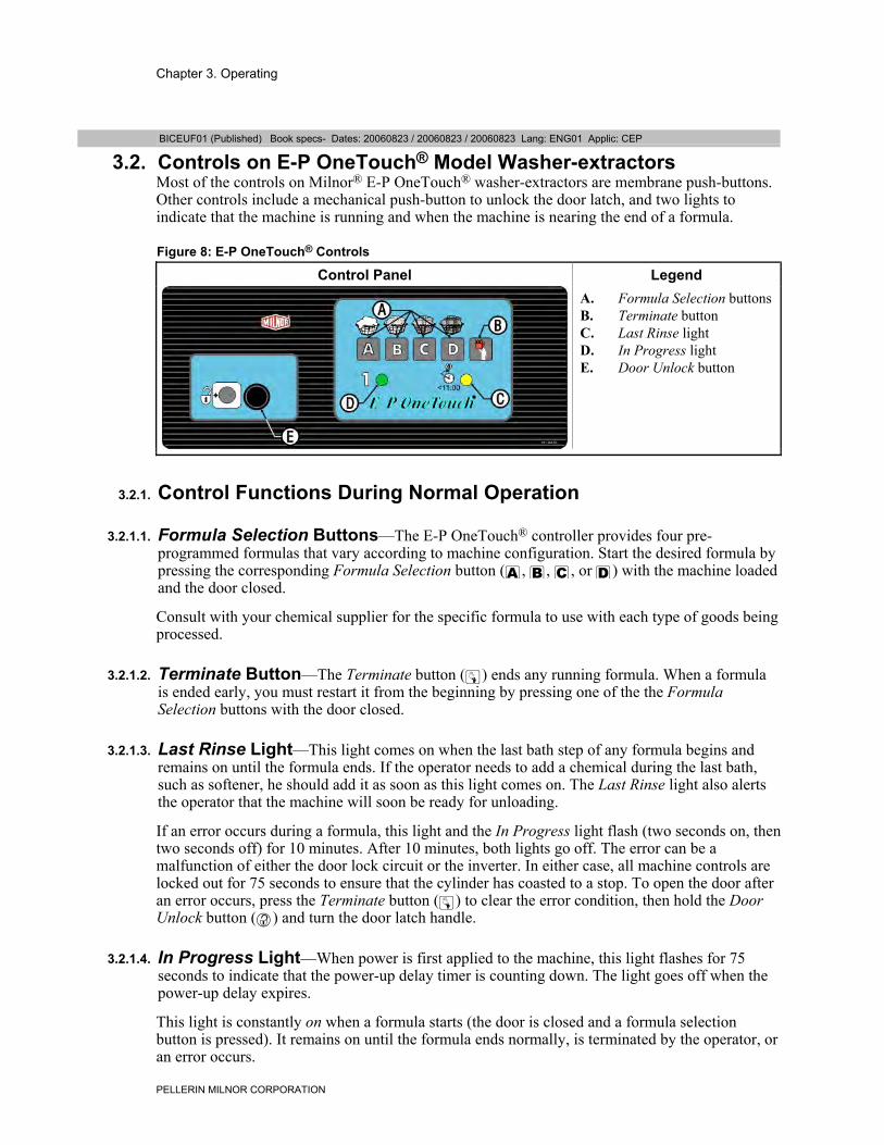
3.2. Controls on E-P OneTouch® Model Washer-extractorsMost of the controls on Milnor® E-P OneTouch® washer-extractors are membrane push-buttons.Other controls include a mechanical push-button to unlock the door latch, and two lights toindicate that the machine is running and when the machine is nearing the end of a formula.
Figure 8: E-P OneTouch® Controls
Control Panel Legend
.
A. Formula Selection buttonsB. Terminate buttonC. Last Rinse lightD. In Progress lightE. Door Unlock button
3.2.1. Control Functions During Normal Operation
3.2.1.1. Formula Selection Buttons—The E-P OneTouch® controller provides four pre-programmed formulas that vary according to machine configuration. Start the desired formula bypressing the corresponding Formula Selection button (", <, >, or ?) with the machine loadedand the door closed.
Consult with your chemical supplier for the specific formula to use with each type of goods beingprocessed.
3.2.1.2. Terminate Button—The Terminate button (z) ends any running formula. When a formulais ended early, you must restart it from the beginning by pressing one of the the FormulaSelection buttons with the door closed.
3.2.1.3. Last Rinse Light—This light comes on when the last bath step of any formula begins andremains on until the formula ends. If the operator needs to add a chemical during the last bath,such as softener, he should add it as soon as this light comes on. The Last Rinse light also alertsthe operator that the machine will soon be ready for unloading.
If an error occurs during a formula, this light and the In Progress light flash (two seconds on, thentwo seconds off) for 10 minutes. After 10 minutes, both lights go off. The error can be amalfunction of either the door lock circuit or the inverter. In either case, all machine controls arelocked out for 75 seconds to ensure that the cylinder has coasted to a stop. To open the door afteran error occurs, press the Terminate button (z) to clear the error condition, then hold the DoorUnlock button (') and turn the door latch handle.
3.2.1.4. In Progress Light—When power is first applied to the machine, this light flashes for 75seconds to indicate that the power-up delay timer is counting down. The light goes off when thepower-up delay expires.
This light is constantly on when a formula starts (the door is closed and a formula selectionbutton is pressed). It remains on until the formula ends normally, is terminated by the operator, oran error occurs.
Chapter 3. Operating
PELLERIN MILNOR CORPORATION
If the formula ends normally by running to completion, the In Progress light goes off when thelast step of the formula ends. If the operator terminates a formula, this light flashes (two secondson, then two seconds off) for 75 seconds as the coast timer counts down. After 75 seconds, holdthe Door Unlock button (') and turn the door latch handle to open the door.
3.2.1.5. Door Unlock Button—This button activates a solenoid in the door latch which unlocks thedoor latch handle, allowing the operator to open the door. To lessen the chance of injury causedby opening the door while the basket is turning, the microprocessor controller disables this buttonwhen a formula starts.
The Door Unlock button is disabled for 75 seconds after a formula ends, whether the formulaended normally, was ended early by the operator, or ended because of an error.
3.2.2. Control Functions During TestingDo not attempt to test or troubleshoot a malfunctioning machine using only the information inthis document. For complete testing procedures, see Section 4.1. “Troubleshooting Errors”.
The display kit referenced in Section 3.2.2.1 consists primarily of a vacuum fluorescent displayand a wiring harness to temporarily connect the display to the processor board for testing byauthorized, qualified technicians. This kit is available from Milnor (see Section ii. “ContactingMilnor®”).
3.2.2.1. Formula Selection Buttons
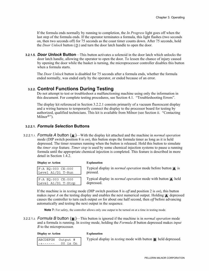
3.2.2.1.1. Formula A button (")—With the display kit attached and the machine in normal operationmode (DIP switch position 8 is on), this button stops the formula timer as long as it is helddepressed. The timer resumes running when the button is released. Hold this button to simulatethe timer stop feature. Timer stop is used by some chemical injection systems to pause a runningformula until the appropriate chemical injection is completed. This feature is described in moredetail in Section 1.4.2.
Display or Action Explanation
F:A EQ:003 CE:000Level A1/D1 T-Run
Typical display in normal operation mode before button " ispressed.
F:A EQ:003 CE:000Level A1/D1 T-Stop
Typical display in normal operation mode with button " helddepressed.
If the machine is in testing mode (DIP switch position 8 is off and position 2 is on), this buttonmakes input A on the testing display and enables the next numerical output. Holding " depressedcauses the controller to turn each output on for about one half second, then off before advancingautomatically and testing the next output in the sequence.
Note 7: For safety, the controller allows only one output to be turned on at a time in testing mode.
3.2.2.1.2. Formula B button (<)—This button is ignored if the machine is in normal operation modeand a formula is running. In testing mode, holding the Formula B button depressed makes inputB to the microprocessor.
Display or Action Explanation
ABCDEFGH Output #-+------ 00 is On
Typical display in testing mode with button < held depressed.
Chapter 3. Operating
PELLERIN MILNOR CORPORATION
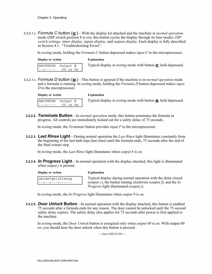
3.2.2.1.3. Formula C button (>)—With the display kit attached and the machine in normal operationmode (DIP switch position 8 is on), this button cycles the display through its four modes: DIPswitch settings, timer display, inputs display, and outputs display. Each display is fully describedin Section 4.1. “Troubleshooting Errors”.
In testing mode, holding the Formula C button depressed makes input C to the microprocessor.
Display or Action Explanation
ABCDEFGH Output #--+----- 00 is On
Typical display in testing mode with button > held depressed.
3.2.2.1.4. Formula D button (?)—This button is ignored if the machine is in normal operation modeand a formula is running. In testing mode, holding the Formula D button depressed makes inputD to the microprocessor.
Display or Action Explanation
ABCDEFGH Output #---+---- 00 is On
Typical display in testing mode with button ? held depressed.
3.2.2.2. Terminate Button—In normal operation mode, this button terminates the formula inprogress. All controls are immediately locked out for a safety delay of 75 seconds.
In testing mode, the Terminate button provides input F to the microprocessor.
3.2.2.3. Last Rinse Light—During normal operation the Last Rinse light illuminates constantly fromthe beginning of the last bath step (last rinse) until the formula ends, 75 seconds after the end ofthe final extract step.
In testing mode, the Last Rinse light illuminates when output 8 is on.
3.2.2.4. In Progress Light—In normal operation with the display attached, this light is illuminatedwhen output j is present.
Display or Action Explanation
abcdefghijklmnop--+--+---+------
Typical display during normal operation with the drain closed(output c), the basket turning clockwise (output f), and the InProgress light illuminated (output j).
In testing mode, the In Progress light illuminates when output 9 is on.
3.2.2.5. Door Unlock Button—In normal operation with the display attached, this button is enabled75 seconds after a formula ends for any reason. The door cannot be unlocked until the 75-secondsafety delay expires. The safety delay also applies for 75 seconds after power is first applied tothe machine.
In testing mode, the Door Unlock button is energized only when output 00 is on. With output 00on, you should hear the door unlock when this button is pressed.
— End of BICEUF01 —
Chapter 3. Operating
PELLERIN MILNOR CORPORATION
BICEUO01 (Published) Book specs- Dates: 20060823 / 20060823 / 20060823 Lang: ENG01 Applic: CEP
3.3. E-P OneTouch® Operation
3.3.1. Instructions for Normal Operation
3.3.1.1. Load the Machine1. If the loading door is closed and latched, hold the Door Unlock button (') to unlock the door
while turning the door latch handle with the other hand. If the door does not unlock, verifythat the machine is connected to power and that the wall disconnect is functioning properly.The machine must have power available to unlock the door.
2. When the door opens, load the machine according to plant guidelines and Section 3.1.“Determining Load Size”.
3. Close the door firmly.
3.3.1.2. Start a Formula
3.3.1.2.1. After a Completed Formula (Normal)—If the previous formula finished normally, simplypress the button that matches the formula you want to run. The selected formula will startimmediately if the door is closed. The Formula Running light (\) illuminates and the door locksimmediately, and the machine fills with water. Once the door is locked, the operator must end theformula early (see Section 3.3.2) or wait for the formula to finish before opening the door.
3.3.1.2.2. After Opening the Door during a Formula—If you ended the previous formula early byopening the door, you must press the Terminate button (z) before you can start the machineagain. The Terminate button also clears any internal machine error that might have caused theformula to end early.
3.3.1.3. Unload the Machine—When the formula ends, the Formula Running light (\) goes out.Hold the Door Unlock button (') to unlock the door while turning the door latch handle with theother hand.
3.3.2. How to End a Formula EarlyYou can end any running formula by pressing the Terminate button (z) on the control panel. Asafety delay keeps the door locked for 75 seconds. When the In Progress light goes off, hold theDoor Unlock button (') to unlock the door while turning the door latch handle with the otherhand.
To resume operation, restart the formula from the beginning by pressing the desired formulabutton.
— End of BICEUO01 —
Chapter 4. Testing and Troubleshooting
PELLERIN MILNOR CORPORATION
Chapter 4Testing and Troubleshooting
BICEUT03 (Published) Book specs- Dates: 20060823 / 20060823 / 20060823 Lang: ENG01 Applic: CEP
4.1. Troubleshooting Errors
4.1.1. Vibration Switch TrippedIf the machine vibrates excessively during extract, the vibration switch (SMWVB in the electricalschematics) closes to ground an input (MTA3-10) to the microprocessor. When the machine is inan extract step and this input is grounded, the controller immediately ends the extract step andstarts the subsequent coast step. The formula then continues normally.
Note 8: The input which indicates that the vibration switch is tripped is shared with the high water levelpressure switch. Software determines whether to turn off the water valve(s) or to signal the inverter to stopthe motor depending on the operation running when the input is grounded.
4.1.2. Door OpenWhen the machine door is closed and the machine is operating normally, contacts 5 and 8 in relayCRDL are closed, grounding the input on MTA3-5 to the microprocessor. If the door opens, theinput is lost. When the microprocessor loses the input, it signals an error and stops the machine.For safety, all machine controls are disabled for 75 seconds after the error occurs.
When this error occurs, the microprocessor signals the error by flashing both the In Progress lightand the Last Rinse light simultaneously. Both lights flash on for two seconds, then off for twoseconds, repeating for 10 minutes. After 10 minutes, both lights remain off.
Press the Terminate button (z) to recover from this error, ensure that the door is securely closed,then start the formula again.
4.1.3. Door/Inverter FaultWhen operating normally, the inverter closes an internal contact wired in series with CRDL pins5 and 8. If the door is closed and the inverter is functioning, the input on MTA3-5 is grounded, asdescribed in Section 4.1.2. If the inverter senses a fault, its internal contacts open and the input onMTA3-5 is lost. This same input is also lost if the door opens during operation. Refer to theinverter documentation for specific troubleshooting procedures.
As happens when the door opens during a formula, the microprocessor signals the error byflashing both the In Progress light and the Last Rinse light simultaneously. Both lights flash onfor two seconds, then off for two seconds, repeating for 10 minutes. After 10 minutes, both lightsremain off.
For safety, all machine controls are disabled for 75 seconds after the error occurs. To open thedoor after this error, you must first wait the 75 seconds until the controls are enabled. Then press
Chapter 4. Testing and Troubleshooting
PELLERIN MILNOR CORPORATION
the Terminate button (z) to clear the error condition. Finally, hold the Door Unlock button (')turn the door latch handle.
After correcting any error with the inverter itself, start the formula again.— End of BICEUT03 —
BICEPT02 (Published) Book specs- Dates: 20060823 / 20060823 / 20060823 Lang: ENG01 Applic: CEP
4.2. Testing MWR_ Washer-extractors
4.2.1. Testing without the Display KitMost functions of this machine can be tested with an accurate digital voltmeter if the schematicdiagrams are available and you have a thorough understanding of how the machine normallyoperates.
The following rules will help you determine the current machine event. The events in eachformula are listed in Section 4.4. “Event Timing for 08BT168BT Controller Boards”.
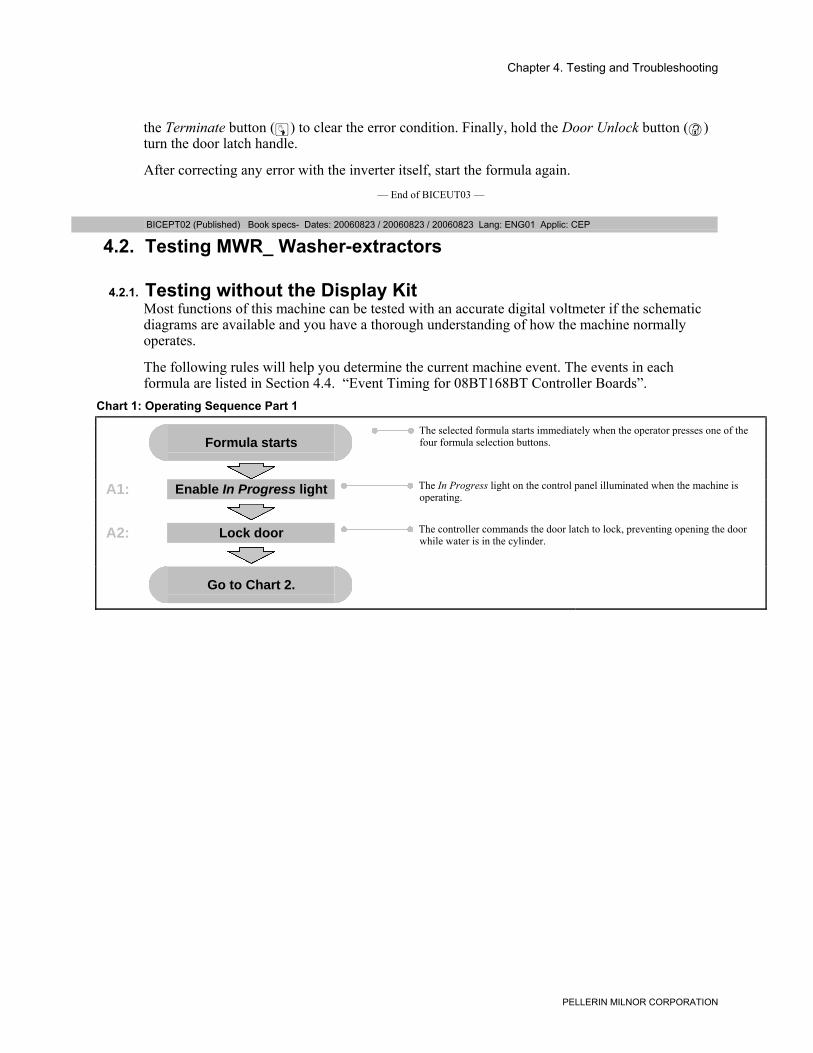
Chart 1: Operating Sequence Part 1
Formula starts The selected formula starts immediately when the operator presses one of the
four formula selection buttons.
A1: Enable In Progress light The In Progress light on the control panel illuminated when the machine isoperating.
A2: Lock door The controller commands the door latch to lock, preventing opening the doorwhile water is in the cylinder.
Go to Chart 2.
Chapter 4. Testing and Troubleshooting
PELLERIN MILNOR CORPORATION
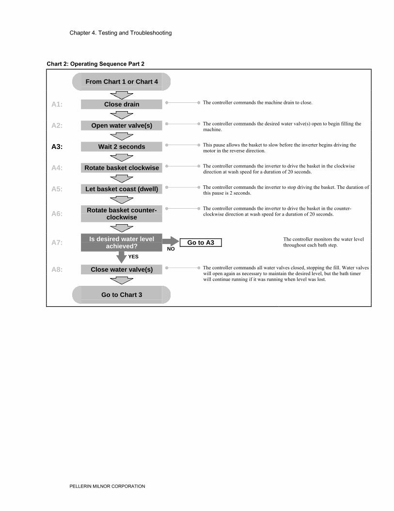
Chart 2: Operating Sequence Part 2
From Chart 1 or Chart 4
A1: Close drain The controller commands the machine drain to close.
A2: Open water valve(s) The controller commands the desired water valve(s) open to begin filling themachine.
A3: Wait 2 seconds This pause allows the basket to slow before the inverter begins driving themotor in the reverse direction.
A4: Rotate basket clockwise The controller commands the inverter to drive the basket in the clockwisedirection at wash speed for a duration of 20 seconds.
A5: Let basket coast (dwell) The controller commands the inverter to stop driving the basket. The duration ofthis pause is 2 seconds.
A6: Rotate basket counter-clockwise
The controller commands the inverter to drive the basket in the counter-clockwise direction at wash speed for a duration of 20 seconds.
A7: Is desired water levelachieved? NO
Go to A3
YES
The controller monitors the water levelthroughout each bath step.
A8: Close water valve(s) The controller commands all water valves closed, stopping the fill. Water valveswill open again as necessary to maintain the desired level, but the bath timerwill continue running if it was running when level was lost.
Go to Chart 3
Chapter 4. Testing and Troubleshooting
PELLERIN MILNOR CORPORATION
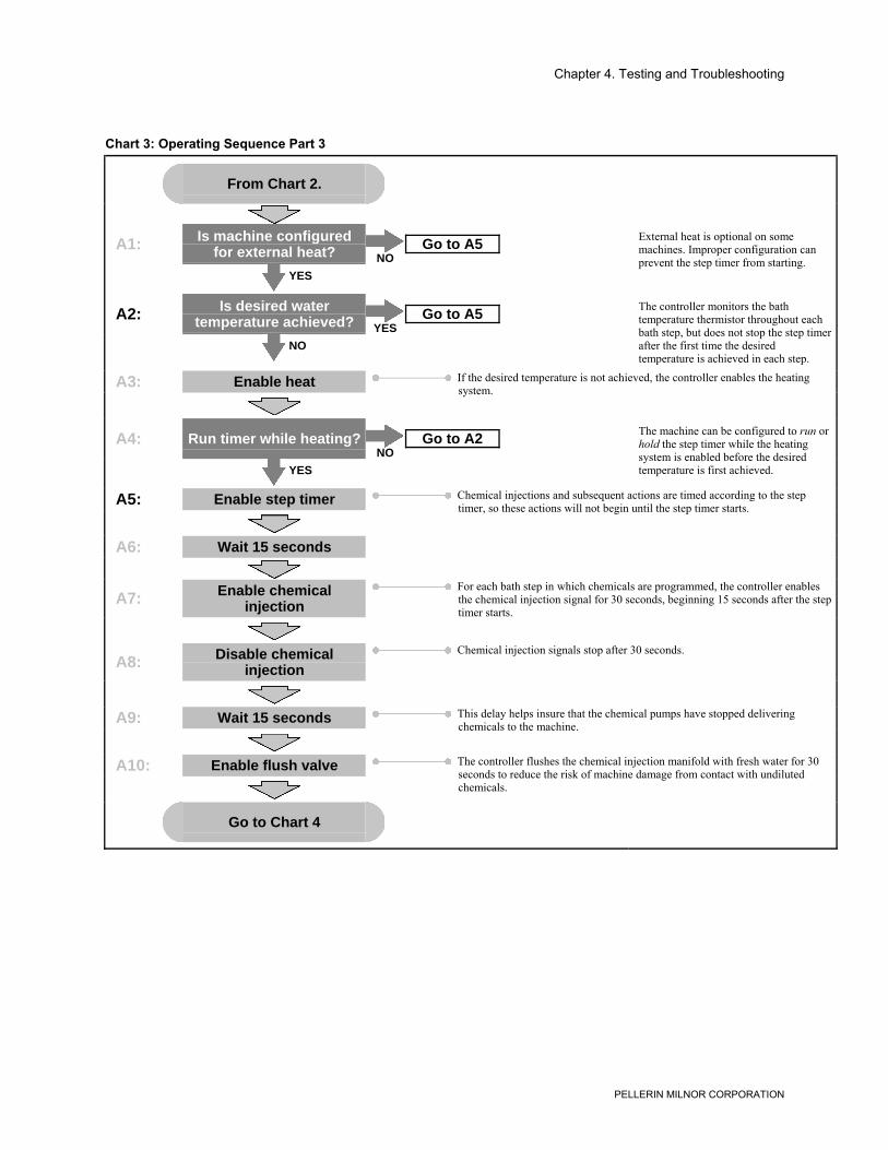
Chart 3: Operating Sequence Part 3
From Chart 2.
A1: Is machine configuredfor external heat? NO
Go to A5
YES
External heat is optional on somemachines. Improper configuration canprevent the step timer from starting.
A2: Is desired watertemperature achieved? YES
Go to A5
NO
The controller monitors the bathtemperature thermistor throughout eachbath step, but does not stop the step timerafter the first time the desiredtemperature is achieved in each step.
A3: Enable heat If the desired temperature is not achieved, the controller enables the heatingsystem.
A4: Run timer while heating?NO
Go to A2
YES
The machine can be configured to run orhold the step timer while the heatingsystem is enabled before the desiredtemperature is first achieved.
A5: Enable step timer Chemical injections and subsequent actions are timed according to the steptimer, so these actions will not begin until the step timer starts.
A6: Wait 15 seconds
A7: Enable chemicalinjection
For each bath step in which chemicals are programmed, the controller enablesthe chemical injection signal for 30 seconds, beginning 15 seconds after the steptimer starts.
A8: Disable chemicalinjection
Chemical injection signals stop after 30 seconds.
A9: Wait 15 seconds This delay helps insure that the chemical pumps have stopped deliveringchemicals to the machine.
A10: Enable flush valve The controller flushes the chemical injection manifold with fresh water for 30seconds to reduce the risk of machine damage from contact with undilutedchemicals.
Go to Chart 4
Chapter 4. Testing and Troubleshooting
PELLERIN MILNOR CORPORATION
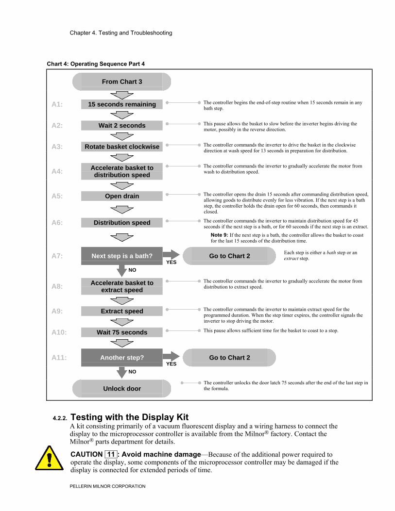
Chart 4: Operating Sequence Part 4
From Chart 3
A1: 15 seconds remaining The controller begins the end-of-step routine when 15 seconds remain in anybath step.
A2: Wait 2 seconds This pause allows the basket to slow before the inverter begins driving themotor, possibly in the reverse direction.
A3: Rotate basket clockwise The controller commands the inverter to drive the basket in the clockwisedirection at wash speed for 13 seconds in preparation for distribution.
A4: Accelerate basket todistribution speed
The controller commands the inverter to gradually accelerate the motor fromwash to distribution speed.
A5: Open drain The controller opens the drain 15 seconds after commanding distribution speed,allowing goods to distribute evenly for less vibration. If the next step is a bathstep, the controller holds the drain open for 60 seconds, then commands itclosed.
A6: Distribution speed The controller commands the inverter to maintain distribution speed for 45seconds if the next step is a bath, or for 60 seconds if the next step is an extract.
Note 9: If the next step is a bath, the controller allows the basket to coastfor the last 15 seconds of the distribution time.
A7: Next step is a bath?YES
Go to Chart 2
NO
Each step is either a bath step or anextract step.
A8: Accelerate basket toextract speed
The controller commands the inverter to gradually accelerate the motor fromdistribution to extract speed.
A9: Extract speed The controller commands the inverter to maintain extract speed for theprogrammed duration. When the step timer expires, the controller signals theinverter to stop driving the motor.
A10: Wait 75 seconds This pause allows sufficient time for the basket to coast to a stop.
A11: Another step?YES
Go to Chart 2
NO
Unlock door The controller unlocks the door latch 75 seconds after the end of the last step in
the formula.
4.2.2. Testing with the Display KitA kit consisting primarily of a vacuum fluorescent display and a wiring harness to connect thedisplay to the microprocessor controller is available from the Milnor® factory. Contact theMilnor® parts department for details.
CAUTION 11 : Avoid machine damage—Because of the additional power required tooperate the display, some components of the microprocessor controller may be damaged if thedisplay is connected for extended periods of time.
Chapter 4. Testing and Troubleshooting
PELLERIN MILNOR CORPORATION
• Connect the display only when testing the machine.• Disconnect the display and replace all control panel covers before returning the machine
to normal operation.
4.2.2.1. Connecting the Display1. Lock off/tag out power to the machine.2. Remove the cabinet top and rear panels to gain access to the microprocessor controller. When
viewed from the rear of the machine, the controller is mounted to your left. Don't try toconnect the display to the large white Magnetek component (motor inverter) to your right.
3. Connect the flat black connector on the display cable to MTA2 on the controller. Use Figure9 as a reference to properly orient the connector to the pins on the controller. The four wiresin the connector should be on the side nearest MTA3, and the two connector sockets withoutwires are nearest the long side of the board.
CAUTION 12 : Avoid personal injury and machine damage—Because the machinemust have power available for testing, use extreme caution when working in the area of highvoltage and moving mechanical parts.• Lock off/tag out power before reaching into the machine.• Route the display wiring clear of the motor and pulleys.
Chapter 4. Testing and Troubleshooting
PELLERIN MILNOR CORPORATION
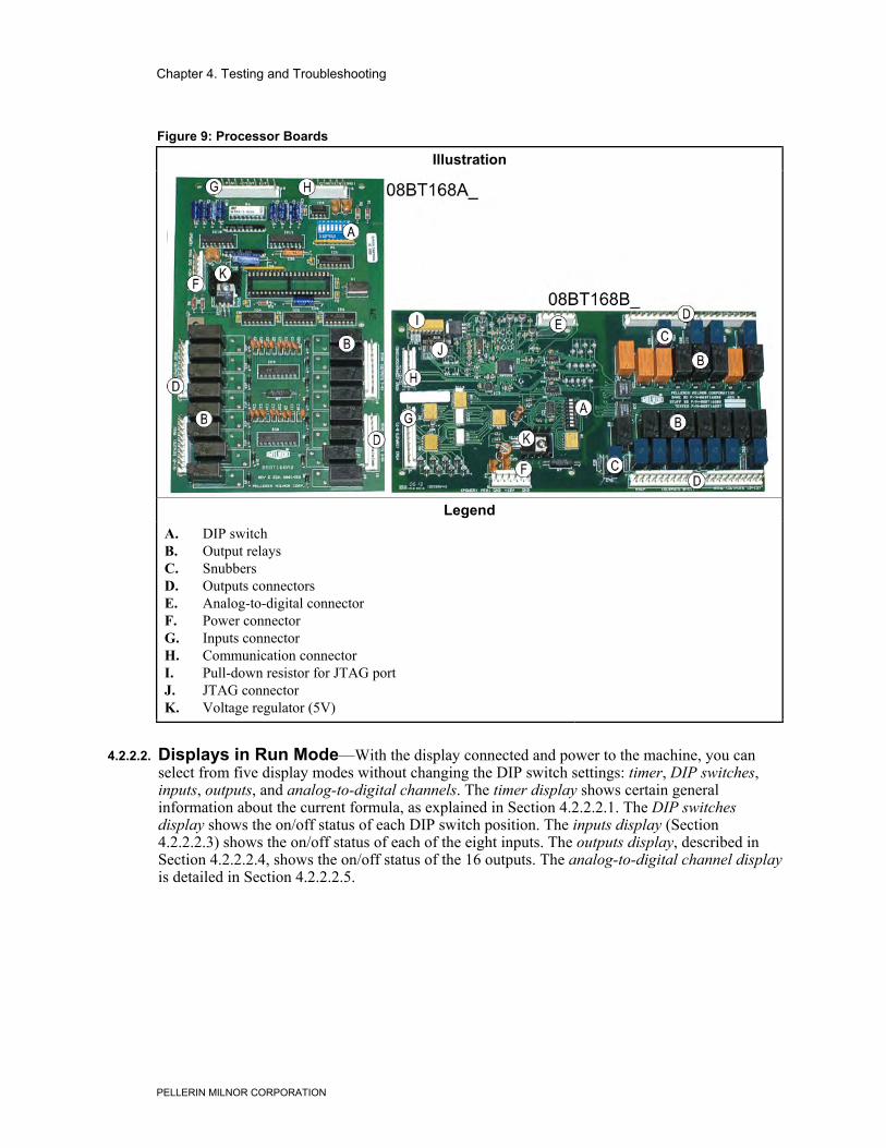
Figure 9: Processor Boards
Illustration
LegendA. DIP switchB. Output relaysC. SnubbersD. Outputs connectorsE. Analog-to-digital connectorF. Power connectorG. Inputs connectorH. Communication connectorI. Pull-down resistor for JTAG portJ. JTAG connectorK. Voltage regulator (5V)
.
4.2.2.2. Displays in Run Mode—With the display connected and power to the machine, you canselect from five display modes without changing the DIP switch settings: timer, DIP switches,inputs, outputs, and analog-to-digital channels. The timer display shows certain generalinformation about the current formula, as explained in Section 4.2.2.2.1. The DIP switchesdisplay shows the on/off status of each DIP switch position. The inputs display (Section4.2.2.2.3) shows the on/off status of each of the eight inputs. The outputs display, described inSection 4.2.2.2.4, shows the on/off status of the 16 outputs. The analog-to-digital channel displayis detailed in Section 4.2.2.2.5.
Chapter 4. Testing and Troubleshooting
PELLERIN MILNOR CORPORATION
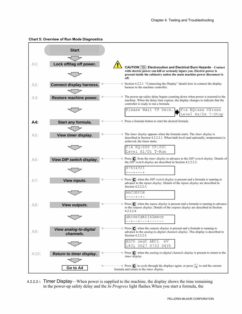
Chart 5: Overview of Run Mode Diagnostics
Start
A1: Lock off/tag off power.CAUTION 13 : Electrocution and Electrical Burn Hazards—Contactwith electric power can kill or seriously injure you. Electric power ispresent inside the cabinetry unless the main machine power disconnect isoff.
A2: Connect display harness. Section 4.2.2.1 “Connecting the Display” details how to connect the displayharness to the machine controller.
A3: Restore machine power. The power-up safety delay begins counting down when power is restored to themachine. When the delay time expires, the display changes to indicate that thecontroller is ready to run a formula.
A4: Start any formula. Press a formula button to start the desired formula.
A5: View timer display. The timer display appears when the formula starts. The timer display isdescribed in Section 4.2.2.2.1. When bath level (and optionally, temperature) isachieved, the timer starts.
A6: View DIP switch display. Press > from the timer display to advance to the DIP switch display. Details ofthe DIP switch display are described in Section 4.2.2.2.2.
A7: View inputs. Press > when the DIP switch display is present and a formula is running toadvance to the inputs display. Details of the inputs display are described inSection 4.2.2.2.3.
A8: View outputs. Press > when the inputs display is present and a formula is running to advanceto the outputs display. Details of the outputs display are described in Section4.2.2.2.4.
A9: View analog-to-digitalchannels.
Press > when the outputs display is present and a formula is running toadvance to the analog-to-digital channels display. This display is described inSection 4.2.2.2.5.
A10: Return to timer display. Press > when the analog-to-digital channels display is present to return to thetimer display.
Go to A4 Press > to cycle through the displays again, or press z to end the current
formula and return to the timer display.
4.2.2.2.1. Timer Display—When power is supplied to the machine, the display shows the time remainingin the power-up safety delay and the In Progress light flashes.When you start a formula, the
Chapter 4. Testing and Troubleshooting
PELLERIN MILNOR CORPORATION
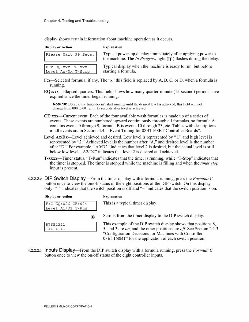
display shows certain information about machine operation as it occurs.
Display or Action Explanation
Please Wait 99 Secs. Typical power-up display immediately after applying power tothe machine. The In Progress light (\) flashes during the delay.
F:x EQ:xxx CE:xxxLevel Ax/Dx T-Stop
Typical display when the machine is ready to run, but beforestarting a formula.
F:x—Selected formula, if any. The “x” this field is replaced by A, B, C, or D, when a formula isrunning.
EQ:xxx—Elapsed quarters. This field shows how many quarter-minute (15-second) periods haveexpired since the timer began running.
Note 10: Because the timer doesn't start running until the desired level is achieved, this field will notchange from 000 to 001 until 15 seconds after level is achieved.
CE:xxx—Current event. Each of the four available wash formulas is made up of a series ofevents. These events are numbered upward continuously through all formulas, so formula Acontains events 0 through 9, formula B is events 10 through 23, etc. Tables with descriptionsof all events are in Section 4.4. “Event Timing for 08BT168BT Controller Boards”.
Level Ax/Dx—Level achieved and desired. Low level is represented by “1,” and high level isrepresented by “2.” Achieved level is the number after “A,” and desired level is the numberafter “D.” For example, “A0/D2” indicates that level 2 is desired, but the actual level is stillbelow low level. “A2/D2” indicates that level 2 is desired and achieved.
T-xxxx—Timer status. “T-Run” indicates that the timer is running, while “T-Stop” indicates thatthe timer is stopped. The timer is stopped while the machine is filling and when the timer stopinput is present.
4.2.2.2.2. DIP Switch Display—From the timer display with a formula running, press the Formula Cbutton once to view the on/off status of the eight positions of the DIP switch. On this displayonly, “+” indicates that the switch position is off and “–” indicates that the switch position is on.
Display or Action Explanation
F:C EQ:026 CE:024Level A1/D1 T-Run
This is a typical timer display.
> Scrolls from the timer display to the DIP switch display.
87654321-++-+-++
This example of the DIP switch display shows that positions 8,5, and 3 are on, and the other positions are off. See Section 2.1.3“Configuration Decisions for Machines with Controller08BT168BT” for the application of each switch position.
4.2.2.2.3. Inputs Display—From the DIP switch display with a formula running, press the Formula Cbutton once to view the on/off status of the eight controller inputs.
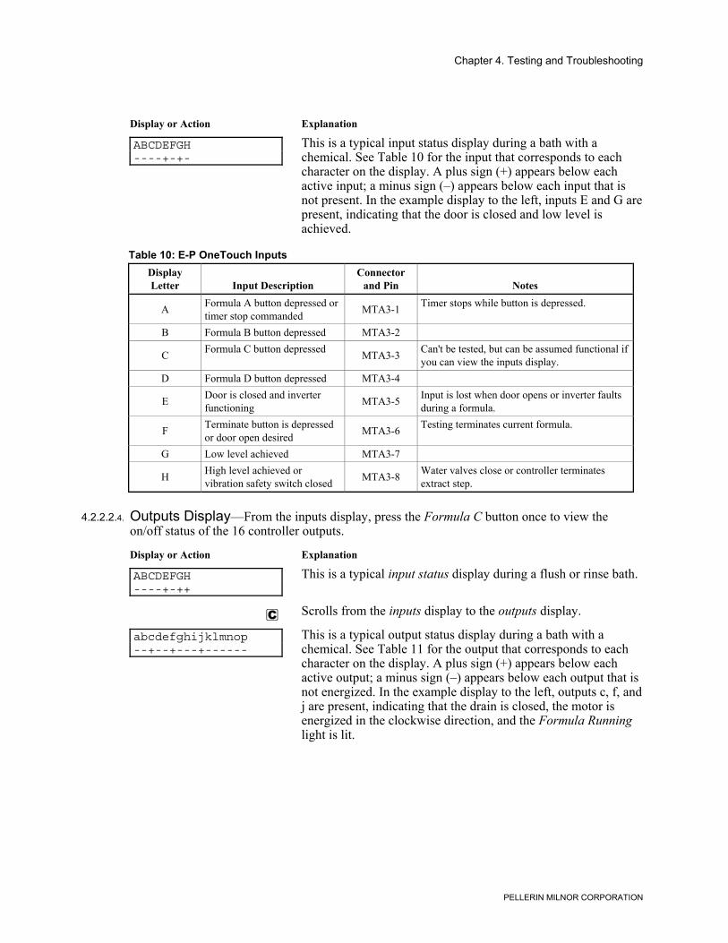
Chapter 4. Testing and Troubleshooting
PELLERIN MILNOR CORPORATION
Display or Action Explanation
ABCDEFGH----+-+-
This is a typical input status display during a bath with achemical. See Table 10 for the input that corresponds to eachcharacter on the display. A plus sign (+) appears below eachactive input; a minus sign (–) appears below each input that isnot present. In the example display to the left, inputs E and G arepresent, indicating that the door is closed and low level isachieved.
Table 10: E-P OneTouch InputsDisplayLetter Input Description
Connectorand Pin Notes
A Formula A button depressed ortimer stop commanded MTA3-1 Timer stops while button is depressed.
B Formula B button depressed MTA3-2
C Formula C button depressed MTA3-3 Can't be tested, but can be assumed functional ifyou can view the inputs display.
D Formula D button depressed MTA3-4
E Door is closed and inverterfunctioning MTA3-5 Input is lost when door opens or inverter faults
during a formula.
F Terminate button is depressedor door open desired MTA3-6 Testing terminates current formula.
G Low level achieved MTA3-7
H High level achieved orvibration safety switch closed MTA3-8 Water valves close or controller terminates
extract step.
4.2.2.2.4. Outputs Display—From the inputs display, press the Formula C button once to view theon/off status of the 16 controller outputs.
Display or Action Explanation
ABCDEFGH----+-++
This is a typical input status display during a flush or rinse bath.
> Scrolls from the inputs display to the outputs display.
abcdefghijklmnop--+--+---+------
This is a typical output status display during a bath with achemical. See Table 11 for the output that corresponds to eachcharacter on the display. A plus sign (+) appears below eachactive output; a minus sign (–) appears below each output that isnot energized. In the example display to the left, outputs c, f, andj are present, indicating that the drain is closed, the motor isenergized in the clockwise direction, and the Formula Runninglight is lit.
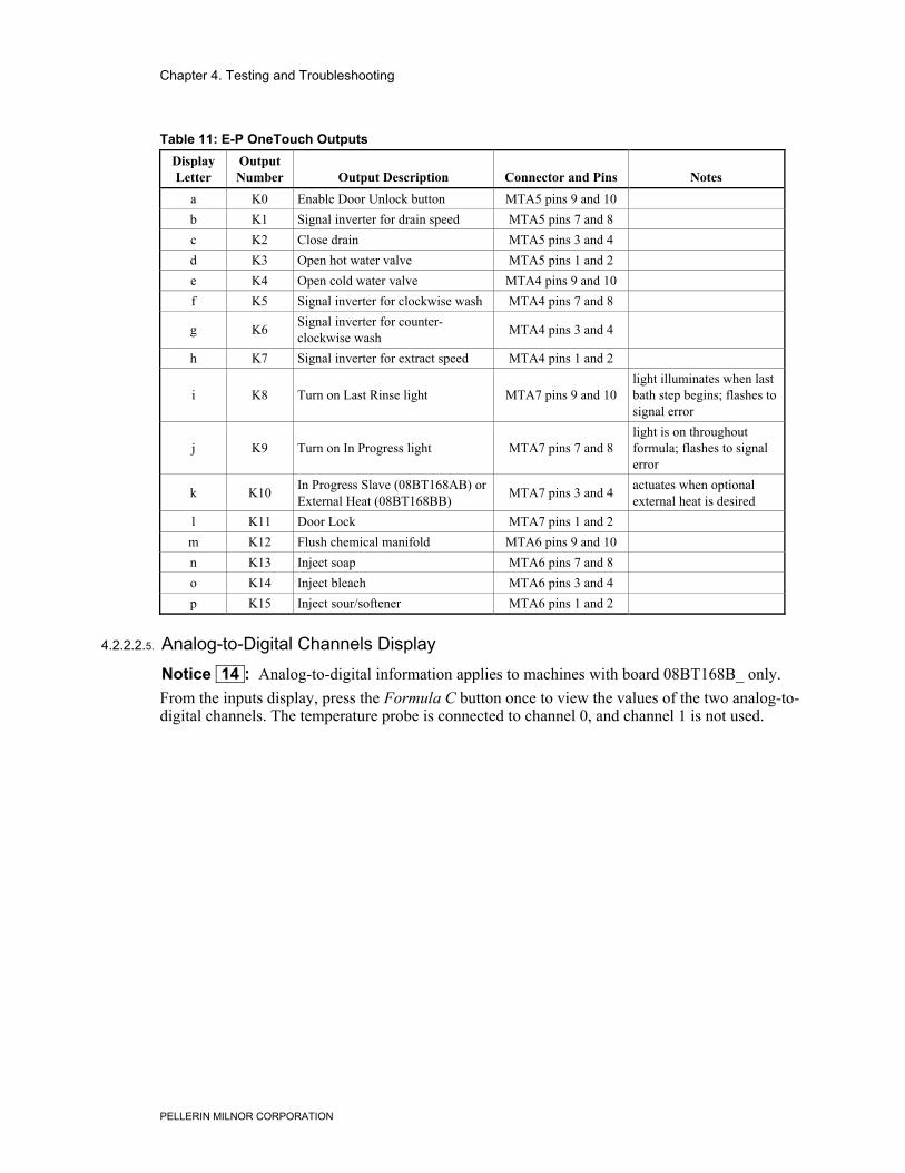
Chapter 4. Testing and Troubleshooting
PELLERIN MILNOR CORPORATION
Table 11: E-P OneTouch OutputsDisplayLetter
OutputNumber Output Description Connector and Pins Notes
a K0 Enable Door Unlock button MTA5 pins 9 and 10b K1 Signal inverter for drain speed MTA5 pins 7 and 8c K2 Close drain MTA5 pins 3 and 4d K3 Open hot water valve MTA5 pins 1 and 2e K4 Open cold water valve MTA4 pins 9 and 10f K5 Signal inverter for clockwise wash MTA4 pins 7 and 8
g K6 Signal inverter for counter-clockwise wash MTA4 pins 3 and 4
h K7 Signal inverter for extract speed MTA4 pins 1 and 2
i K8 Turn on Last Rinse light MTA7 pins 9 and 10light illuminates when lastbath step begins; flashes tosignal error
j K9 Turn on In Progress light MTA7 pins 7 and 8light is on throughoutformula; flashes to signalerror
k K10 In Progress Slave (08BT168AB) orExternal Heat (08BT168BB) MTA7 pins 3 and 4 actuates when optional
external heat is desiredl K11 Door Lock MTA7 pins 1 and 2m K12 Flush chemical manifold MTA6 pins 9 and 10n K13 Inject soap MTA6 pins 7 and 8o K14 Inject bleach MTA6 pins 3 and 4p K15 Inject sour/softener MTA6 pins 1 and 2
4.2.2.2.5. Analog-to-Digital Channels Display
Notice 14 : Analog-to-digital information applies to machines with board 08BT168B_ only.From the inputs display, press the Formula C button once to view the values of the two analog-to-digital channels. The temperature probe is connected to channel 0, and channel 1 is not used.
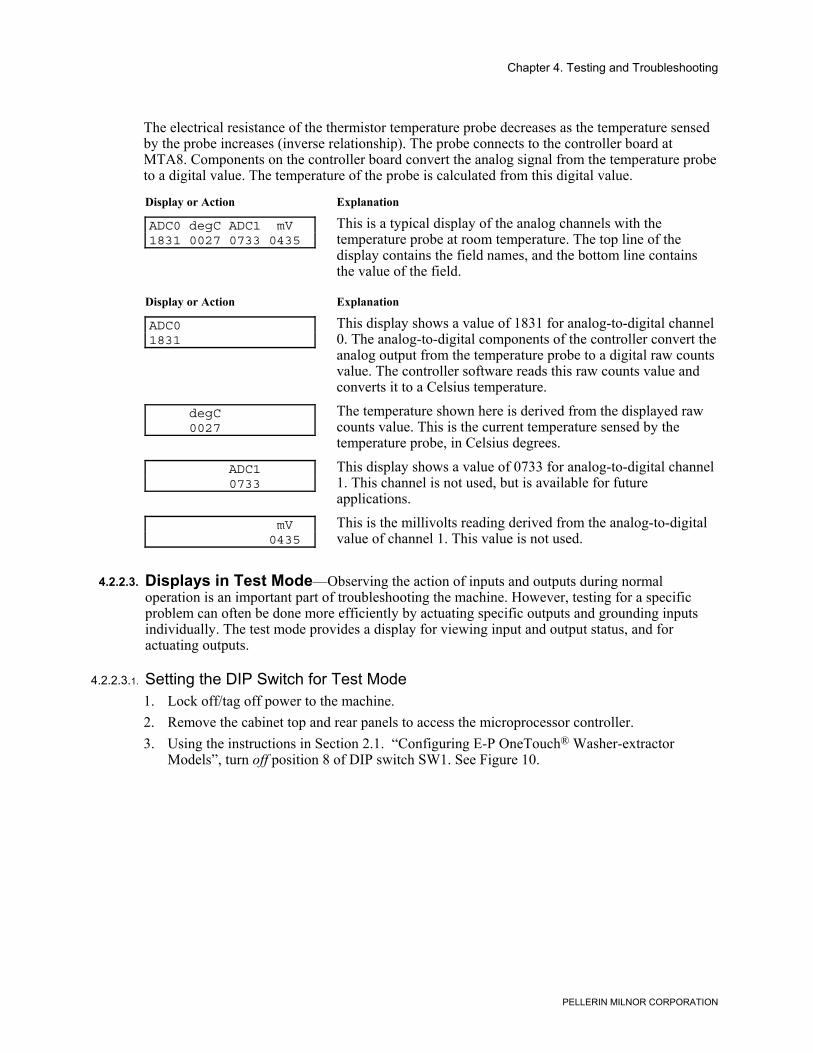
Chapter 4. Testing and Troubleshooting
PELLERIN MILNOR CORPORATION
The electrical resistance of the thermistor temperature probe decreases as the temperature sensedby the probe increases (inverse relationship). The probe connects to the controller board atMTA8. Components on the controller board convert the analog signal from the temperature probeto a digital value. The temperature of the probe is calculated from this digital value.
Display or Action Explanation
ADC0 degC ADC1 mV1831 0027 0733 0435
This is a typical display of the analog channels with thetemperature probe at room temperature. The top line of thedisplay contains the field names, and the bottom line containsthe value of the field.
Display or Action Explanation
ADC01831
This display shows a value of 1831 for analog-to-digital channel0. The analog-to-digital components of the controller convert theanalog output from the temperature probe to a digital raw countsvalue. The controller software reads this raw counts value andconverts it to a Celsius temperature.
degC 0027
The temperature shown here is derived from the displayed rawcounts value. This is the current temperature sensed by thetemperature probe, in Celsius degrees.
ADC1 0733
This display shows a value of 0733 for analog-to-digital channel1. This channel is not used, but is available for futureapplications.
mV 0435
This is the millivolts reading derived from the analog-to-digitalvalue of channel 1. This value is not used.
4.2.2.3. Displays in Test Mode—Observing the action of inputs and outputs during normaloperation is an important part of troubleshooting the machine. However, testing for a specificproblem can often be done more efficiently by actuating specific outputs and grounding inputsindividually. The test mode provides a display for viewing input and output status, and foractuating outputs.
4.2.2.3.1. Setting the DIP Switch for Test Mode1. Lock off/tag off power to the machine.2. Remove the cabinet top and rear panels to access the microprocessor controller.3. Using the instructions in Section 2.1. “Configuring E-P OneTouch® Washer-extractor
Models”, turn off position 8 of DIP switch SW1. See Figure 10.
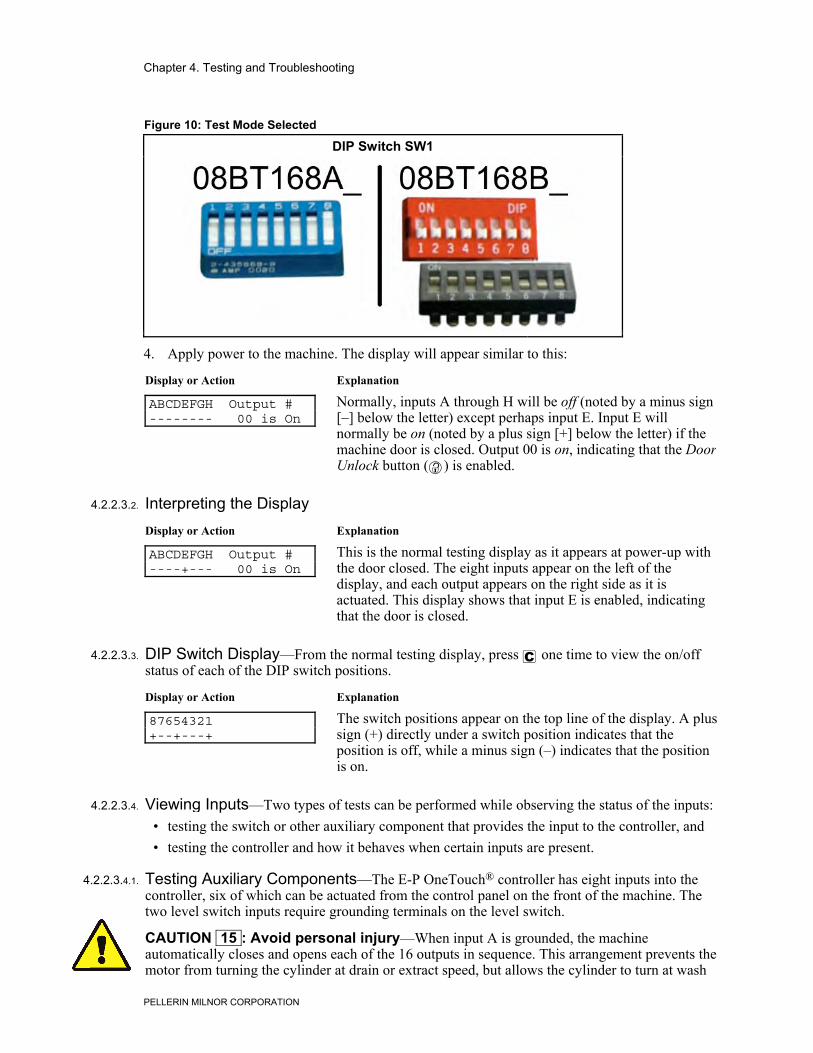
Chapter 4. Testing and Troubleshooting
PELLERIN MILNOR CORPORATION
Figure 10: Test Mode Selected
DIP Switch SW1
.
4. Apply power to the machine. The display will appear similar to this:
Display or Action Explanation
ABCDEFGH Output #-------- 00 is On
Normally, inputs A through H will be off (noted by a minus sign[–] below the letter) except perhaps input E. Input E willnormally be on (noted by a plus sign [+] below the letter) if themachine door is closed. Output 00 is on, indicating that the DoorUnlock button (') is enabled.
4.2.2.3.2. Interpreting the DisplayDisplay or Action Explanation
ABCDEFGH Output #----+--- 00 is On
This is the normal testing display as it appears at power-up withthe door closed. The eight inputs appear on the left of thedisplay, and each output appears on the right side as it isactuated. This display shows that input E is enabled, indicatingthat the door is closed.
4.2.2.3.3. DIP Switch Display—From the normal testing display, press > one time to view the on/offstatus of each of the DIP switch positions.
Display or Action Explanation
87654321+--+---+
The switch positions appear on the top line of the display. A plussign (+) directly under a switch position indicates that theposition is off, while a minus sign (–) indicates that the positionis on.
4.2.2.3.4. Viewing Inputs—Two types of tests can be performed while observing the status of the inputs:• testing the switch or other auxiliary component that provides the input to the controller, and• testing the controller and how it behaves when certain inputs are present.
4.2.2.3.4.1. Testing Auxiliary Components—The E-P OneTouch® controller has eight inputs into thecontroller, six of which can be actuated from the control panel on the front of the machine. Thetwo level switch inputs require grounding terminals on the level switch.
CAUTION 15 : Avoid personal injury—When input A is grounded, the machineautomatically closes and opens each of the 16 outputs in sequence. This arrangement prevents themotor from turning the cylinder at drain or extract speed, but allows the cylinder to turn at wash
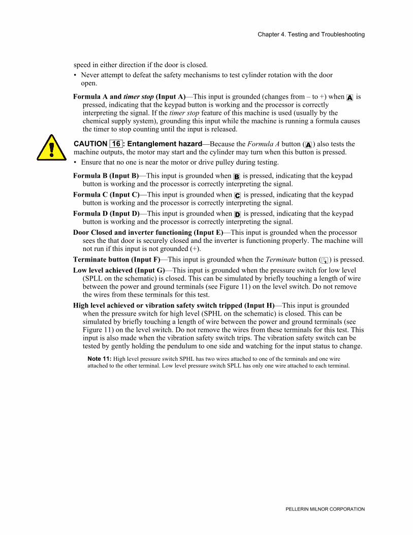
Chapter 4. Testing and Troubleshooting
PELLERIN MILNOR CORPORATION
speed in either direction if the door is closed.• Never attempt to defeat the safety mechanisms to test cylinder rotation with the door
open.
Formula A and timer stop (Input A)—This input is grounded (changes from – to +) when " ispressed, indicating that the keypad button is working and the processor is correctlyinterpreting the signal. If the timer stop feature of this machine is used (usually by thechemical supply system), grounding this input while the machine is running a formula causesthe timer to stop counting until the input is released.
CAUTION 16 : Entanglement hazard—Because the Formula A button (") also tests themachine outputs, the motor may start and the cylinder may turn when this button is pressed.• Ensure that no one is near the motor or drive pulley during testing.
Formula B (Input B)—This input is grounded when < is pressed, indicating that the keypadbutton is working and the processor is correctly interpreting the signal.
Formula C (Input C)—This input is grounded when > is pressed, indicating that the keypadbutton is working and the processor is correctly interpreting the signal.
Formula D (Input D)—This input is grounded when ? is pressed, indicating that the keypadbutton is working and the processor is correctly interpreting the signal.
Door Closed and inverter functioning (Input E)—This input is grounded when the processorsees the that door is securely closed and the inverter is functioning properly. The machine willnot run if this input is not grounded (+).
Terminate button (Input F)—This input is grounded when the Terminate button (z) is pressed.Low level achieved (Input G)—This input is grounded when the pressure switch for low level
(SPLL on the schematic) is closed. This can be simulated by briefly touching a length of wirebetween the power and ground terminals (see Figure 11) on the level switch. Do not removethe wires from these terminals for this test.
High level achieved or vibration safety switch tripped (Input H)—This input is groundedwhen the pressure switch for high level (SPHL on the schematic) is closed. This can besimulated by briefly touching a length of wire between the power and ground terminals (seeFigure 11) on the level switch. Do not remove the wires from these terminals for this test. Thisinput is also made when the vibration safety switch trips. The vibration safety switch can betested by gently holding the pendulum to one side and watching for the input status to change.
Note 11: High level pressure switch SPHL has two wires attached to one of the terminals and one wireattached to the other terminal. Low level pressure switch SPLL has only one wire attached to each terminal.
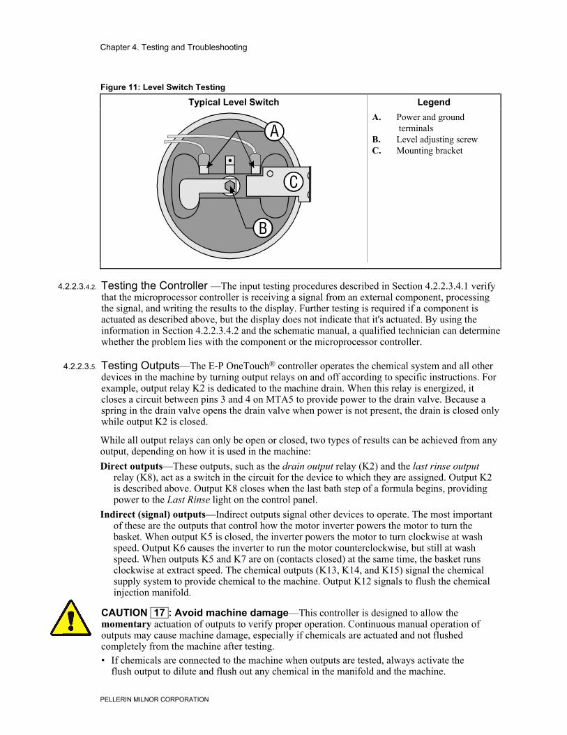
Chapter 4. Testing and Troubleshooting
PELLERIN MILNOR CORPORATION
Figure 11: Level Switch Testing
Typical Level Switch Legend
.
A. Power and groundterminals
B. Level adjusting screwC. Mounting bracket
4.2.2.3.4.2. Testing the Controller —The input testing procedures described in Section 4.2.2.3.4.1 verifythat the microprocessor controller is receiving a signal from an external component, processingthe signal, and writing the results to the display. Further testing is required if a component isactuated as described above, but the display does not indicate that it's actuated. By using theinformation in Section 4.2.2.3.4.2 and the schematic manual, a qualified technician can determinewhether the problem lies with the component or the microprocessor controller.
4.2.2.3.5. Testing Outputs—The E-P OneTouch® controller operates the chemical system and all otherdevices in the machine by turning output relays on and off according to specific instructions. Forexample, output relay K2 is dedicated to the machine drain. When this relay is energized, itcloses a circuit between pins 3 and 4 on MTA5 to provide power to the drain valve. Because aspring in the drain valve opens the drain valve when power is not present, the drain is closed onlywhile output K2 is closed.
While all output relays can only be open or closed, two types of results can be achieved from anyoutput, depending on how it is used in the machine:Direct outputs—These outputs, such as the drain output relay (K2) and the last rinse output
relay (K8), act as a switch in the circuit for the device to which they are assigned. Output K2is described above. Output K8 closes when the last bath step of a formula begins, providingpower to the Last Rinse light on the control panel.
Indirect (signal) outputs—Indirect outputs signal other devices to operate. The most importantof these are the outputs that control how the motor inverter powers the motor to turn thebasket. When output K5 is closed, the inverter powers the motor to turn clockwise at washspeed. Output K6 causes the inverter to run the motor counterclockwise, but still at washspeed. When outputs K5 and K7 are on (contacts closed) at the same time, the basket runsclockwise at extract speed. The chemical outputs (K13, K14, and K15) signal the chemicalsupply system to provide chemical to the machine. Output K12 signals to flush the chemicalinjection manifold.
CAUTION 17 : Avoid machine damage—This controller is designed to allow themomentary actuation of outputs to verify proper operation. Continuous manual operation ofoutputs may cause machine damage, especially if chemicals are actuated and not flushedcompletely from the machine after testing.• If chemicals are connected to the machine when outputs are tested, always activate the
flush output to dilute and flush out any chemical in the manifold and the machine.
Chapter 4. Testing and Troubleshooting
PELLERIN MILNOR CORPORATION
Display or Action Explanation
" Press and release this button to turn off the current output andselect and actuate the next one. For example, if the display says,“Output #3 is On,” press " one time and release it to turn offoutput 3 and turn on output 4. The display then shows, “Output#4 is On.”
Hold this button depressed to automatically cycle through all 16outputs. As described above, only one output is actuated at anytime. The display will turn each output on for approximately onehalf second, then advance to the next output in numerical order.
The goal in testing outputs is to verify that the specified device operates when the controllercommands it to operate. Some devices, such as water valves and chemical injections, cause aresult that can be seen or heard (water or chemical entering the machine). Others, especially drainand extract speed commands, can only be verified with the proper use of a voltmeter. Use theinformation below and the electrical diagrams for this machine to test a component.Door Unlock button (Output 00)—When this output is enabled, it remains enabled for two
seconds before it turns off. While enabled, this relay enables relay CRD to lock the door. TheDoor Unlock button (') must be held depressed while testing this output or it will notenergize.
Drain Speed inverter signal (Output 01)—This output signals the inverter to run the motor atdrain speed. However, both the clockwise wash signal and the drain speed signal must bepresent for the basket to turn. Test this output relay (K01) by checking for a signal of 24 voltsDC between pins 7 and 8 of MTA5 when the relay should be off, dropping to 0 volts when therelay should be on.
Drain Closed (Output 02)—This output relay closes to energize the normally-open drain valve,causing it to close. Test relay K02 by observing the drain valve under the machine or bychecking for control voltage between fuse EF71B and pin 3 of MTA5 when the relay shouldbe closed (drain closed), dropping to 0 volts when the relay should be open (drain open).
Hot Water Valve On (Output 03)—This output relay closes to energize the normally-closed hotwater valve, causing it to open. A voltmeter should indicate control circuit voltage betweenfuse EF71B and pin 1 of MTA5 when the valve is open and hot water is flowing into themachine, dropping to 0 when the valve is closed.
Cold Water Valve On (Output 04)—This output relay closes to energize the normally-closedcold water valve, causing it to open. A voltmeter should indicate control circuit voltagebetween fuse EF71B and pin 9 of MTA4 when the valve is open and cold water is flowinginto the machine, dropping to 0 when the valve is closed.
CAUTION 18 : Entanglement hazard—The machine basket rotates when output 05 or 06 isactuated.• Keep all personnel clear of the motor and drive components when testing these outputs.
Clockwise Wash Speed inverter signal (Output 05)—This output signals the inverter to run themotor clockwise at wash speed. Test this output relay (K05) by checking for a signal of 24volts DC between pins 7 and 8 of MTA4 when the relay should be off, dropping to 0 voltswhen the relay should be on.
Counter-clockwise Wash Speed inverter signal (Output 06)—This output signals the inverterto run the motor counter-clockwise at wash speed. Test this output relay (K06) by checkingfor a signal of 24 volts DC between pins 3 and 4 of MTA4 when the relay should be off,dropping to 0 volts when the relay should be on.
Chapter 4. Testing and Troubleshooting
PELLERIN MILNOR CORPORATION
Extract Speed inverter signal (Output 07)—This output signals the inverter to run the motor atextract speed. However, both the clockwise wash signal and the extract speed signal must bepresent for the basket to turn. Test this output relay (K07) by checking for a signal of 24 voltsDC between pins 1 and 2 of MTA4 when the relay should be off, dropping to 0 volts when therelay should be on.
Last Rinse Light On (Output 08)—Output K08 closes to power the Last Rinse light on thecontrol panel. When the output is on, a voltmeter will read the control circuit voltage betweenfuse EF71B and pin 10 of MTA7. When the output is turned off, the voltage drops to 0.
In Progress Light On (Output 09)—When output relay K09 is on, the In Progress light shouldbe on and a voltmeter should read control circuit voltage between fuse EF71B and pin 8 ofMTA7.
In Progress Light slave (Output 10 on controller board 08BT168A_ only)—This relayoperates identically to output 09, but is usually used to verify that the machine is running aformula before allowing the chemical supply system to stop the machine timer.
External Heat On (Output 10 on controller board 08BT168B_ only)—This relay closes whenthe controller desires external heat to increase the bath temperature. The relay opens when theconfigured temperature is achieved, the bath step runs to completion, or an error terminatesthe wash formula.
Door Lock (Output 11)—When this output is actuated, it remains enabled for two seconds, thenturns off. While enabled, this relay powers relay CRE to lock the door.
Flush Chemical Manifold (Output 12)—When this output is on, control voltage flows betweenfuse EF71B and pin 1 of MTA7. This signal tells the chemical supply system that thechemical injection is complete and the machine desires to flush the chemical injectionmanifold.
Inject Detergent (Output 13)—When this output is on, control voltage flows between fuseEF71B and pin 7 of MTA6. This signal tells the chemical supply system that the machinedesires detergent.
Inject Bleach (Output 14)—When this output is on, control voltage flows between fuse EF71Band pin 3 of MTA6. This signal tells the chemical supply system that the machine desiresbleach.
Inject Sour/softener (Output 15)—When this output is on, control voltage flows between fuseEF71B and pin 1 of MTA6. This signal tells the chemical supply system that the machinedesires sour/softener or sour/starch.
Low Level Test (Output 16)—This test is designed primarily for calibrating low level pressureswitch SPLL. When this functional test is started, the drain closes and the cold water valveopens. The water valve closes when low level is achieved, indicated on the display by input Gchanging from a minus sign (–) to a plus sign (+).
Note 12: The door must be closed during this test.
High Level Test (Output 17)—This test is designed primarily for calibrating high level pressureswitch SPHL. When this functional test is started, the drain closes if it was open and the coldwater valve opens. The water valve closes when high level is achieved, indicated on thedisplay by input H changing from a minus sign (–) to a plus sign (+).
Note 13: The door must be closed during this test.
Basket Speed Test (Output 18)—This test runs the cylinder at each of the three availablespeeds, as described below:
Note 14: The door must be closed during this test.
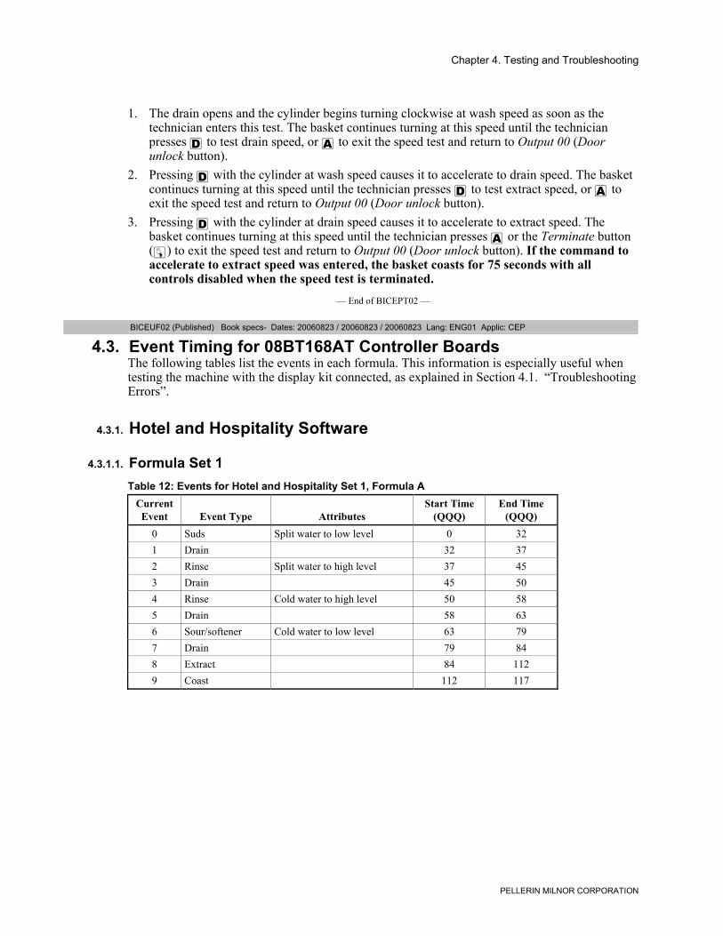
Chapter 4. Testing and Troubleshooting
PELLERIN MILNOR CORPORATION
1. The drain opens and the cylinder begins turning clockwise at wash speed as soon as thetechnician enters this test. The basket continues turning at this speed until the technicianpresses ? to test drain speed, or " to exit the speed test and return to Output 00 (Doorunlock button).
2. Pressing ? with the cylinder at wash speed causes it to accelerate to drain speed. The basketcontinues turning at this speed until the technician presses ? to test extract speed, or " toexit the speed test and return to Output 00 (Door unlock button).
3. Pressing ? with the cylinder at drain speed causes it to accelerate to extract speed. Thebasket continues turning at this speed until the technician presses " or the Terminate button(z) to exit the speed test and return to Output 00 (Door unlock button). If the command toaccelerate to extract speed was entered, the basket coasts for 75 seconds with allcontrols disabled when the speed test is terminated.
— End of BICEPT02 —
BICEUF02 (Published) Book specs- Dates: 20060823 / 20060823 / 20060823 Lang: ENG01 Applic: CEP
4.3. Event Timing for 08BT168AT Controller BoardsThe following tables list the events in each formula. This information is especially useful whentesting the machine with the display kit connected, as explained in Section 4.1. “TroubleshootingErrors”.
4.3.1. Hotel and Hospitality Software
4.3.1.1. Formula Set 1Table 12: Events for Hotel and Hospitality Set 1, Formula A
CurrentEvent Event Type Attributes
Start Time(QQQ)
End Time(QQQ)
0 Suds Split water to low level 0 321 Drain 32 372 Rinse Split water to high level 37 453 Drain 45 504 Rinse Cold water to high level 50 585 Drain 58 636 Sour/softener Cold water to low level 63 797 Drain 79 848 Extract 84 1129 Coast 112 117
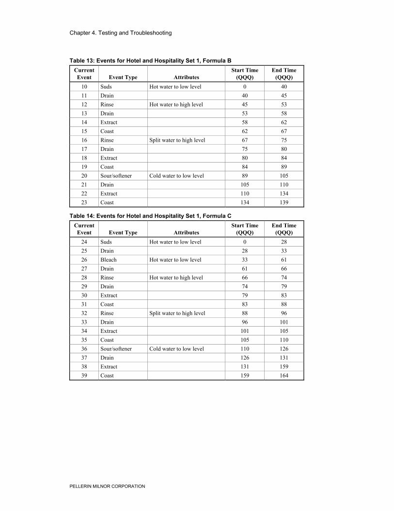
Chapter 4. Testing and Troubleshooting
PELLERIN MILNOR CORPORATION
Table 13: Events for Hotel and Hospitality Set 1, Formula BCurrentEvent Event Type Attributes
Start Time(QQQ)
End Time(QQQ)
10 Suds Hot water to low level 0 4011 Drain 40 4512 Rinse Hot water to high level 45 5313 Drain 53 5814 Extract 58 6215 Coast 62 6716 Rinse Split water to high level 67 7517 Drain 75 8018 Extract 80 8419 Coast 84 8920 Sour/softener Cold water to low level 89 10521 Drain 105 11022 Extract 110 13423 Coast 134 139
Table 14: Events for Hotel and Hospitality Set 1, Formula CCurrentEvent Event Type Attributes
Start Time(QQQ)
End Time(QQQ)
24 Suds Hot water to low level 0 2825 Drain 28 3326 Bleach Hot water to low level 33 6127 Drain 61 6628 Rinse Hot water to high level 66 7429 Drain 74 7930 Extract 79 8331 Coast 83 8832 Rinse Split water to high level 88 9633 Drain 96 10134 Extract 101 10535 Coast 105 11036 Sour/softener Cold water to low level 110 12637 Drain 126 13138 Extract 131 15939 Coast 159 164
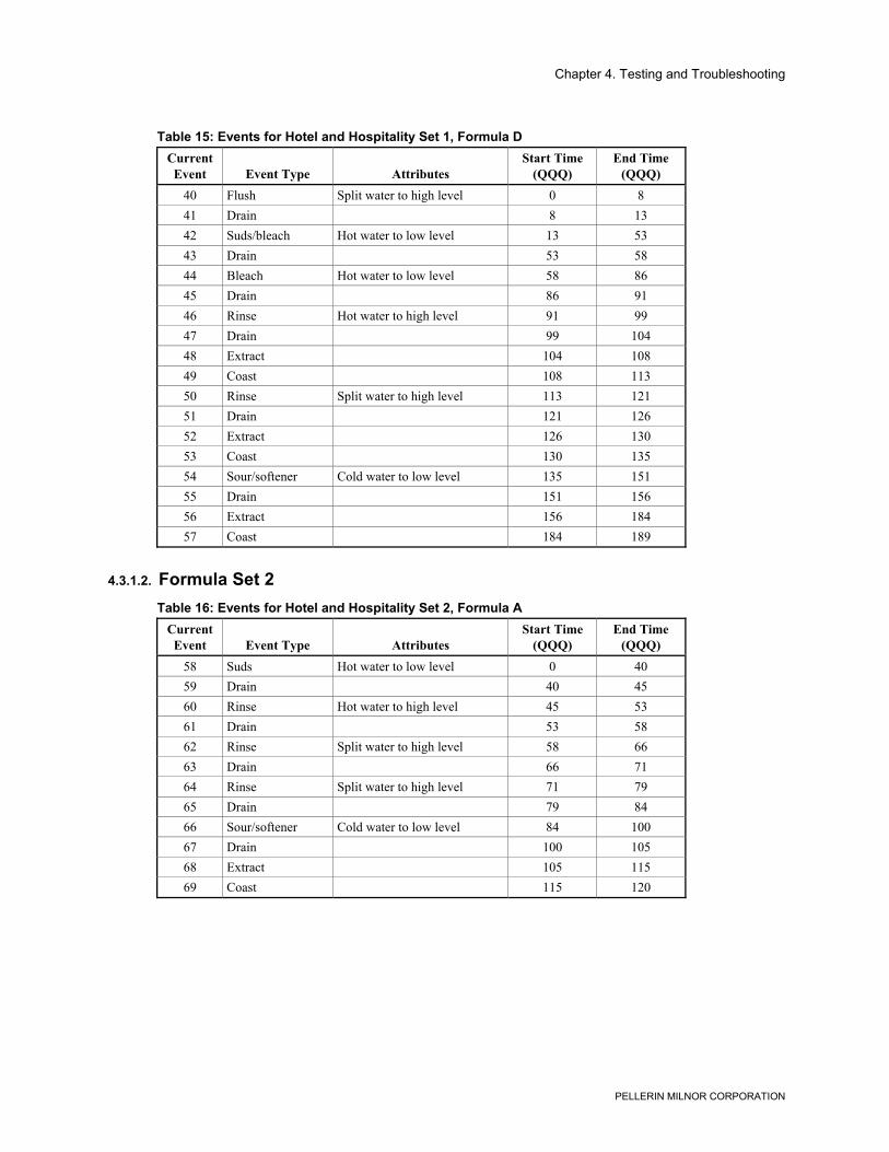
Chapter 4. Testing and Troubleshooting
PELLERIN MILNOR CORPORATION
Table 15: Events for Hotel and Hospitality Set 1, Formula DCurrentEvent Event Type Attributes
Start Time(QQQ)
End Time(QQQ)
40 Flush Split water to high level 0 841 Drain 8 1342 Suds/bleach Hot water to low level 13 5343 Drain 53 5844 Bleach Hot water to low level 58 8645 Drain 86 9146 Rinse Hot water to high level 91 9947 Drain 99 10448 Extract 104 10849 Coast 108 11350 Rinse Split water to high level 113 12151 Drain 121 12652 Extract 126 13053 Coast 130 13554 Sour/softener Cold water to low level 135 15155 Drain 151 15656 Extract 156 18457 Coast 184 189
4.3.1.2. Formula Set 2Table 16: Events for Hotel and Hospitality Set 2, Formula A
CurrentEvent Event Type Attributes
Start Time(QQQ)
End Time(QQQ)
58 Suds Hot water to low level 0 4059 Drain 40 4560 Rinse Hot water to high level 45 5361 Drain 53 5862 Rinse Split water to high level 58 6663 Drain 66 7164 Rinse Split water to high level 71 7965 Drain 79 8466 Sour/softener Cold water to low level 84 10067 Drain 100 10568 Extract 105 11569 Coast 115 120

Chapter 4. Testing and Troubleshooting
PELLERIN MILNOR CORPORATION
Table 17: Events for Hotel and Hospitality Set 2, Formula BCurrentEvent Event Type Attributes
Start Time(QQQ)
End Time(QQQ)
70 Suds Hot water to low level 0 4071 Drain 40 4572 Bleach Hot water to low level 45 7373 Drain 73 7874 Rinse Split water to high level 78 8675 Drain 86 9176 Rinse Split water to high level 91 9977 Drain 99 10478 Sour/softener Cold water to low level 104 12079 Drain 120 12580 Extract 125 13581 Coast 135 140
Table 18: Events for Hotel and Hospitality Set 2, Formula CCurrentEvent Event Type Attributes
Start Time(QQQ)
End Time(QQQ)
82 Suds and bleach Hot water to low level 0 8083 Drain 80 8584 Rinse Hot water to high level 85 9385 Drain 93 9886 Rinse Hot water to high level 98 10687 Drain 106 11188 Rinse Split water to high level 111 11989 Drain 119 12490 Extract 124 12991 Coast 129 13492 Rinse Split water to high level 134 14293 Drain 142 14794 Extract 147 17595 Coast 175 180
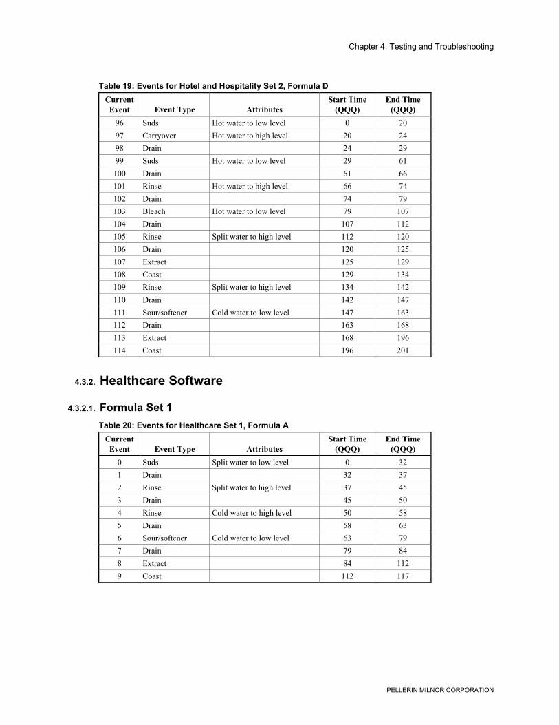
Chapter 4. Testing and Troubleshooting
PELLERIN MILNOR CORPORATION
Table 19: Events for Hotel and Hospitality Set 2, Formula DCurrentEvent Event Type Attributes
Start Time(QQQ)
End Time(QQQ)
96 Suds Hot water to low level 0 2097 Carryover Hot water to high level 20 2498 Drain 24 2999 Suds Hot water to low level 29 61
100 Drain 61 66101 Rinse Hot water to high level 66 74102 Drain 74 79103 Bleach Hot water to low level 79 107104 Drain 107 112105 Rinse Split water to high level 112 120106 Drain 120 125107 Extract 125 129108 Coast 129 134109 Rinse Split water to high level 134 142110 Drain 142 147111 Sour/softener Cold water to low level 147 163112 Drain 163 168113 Extract 168 196114 Coast 196 201
4.3.2. Healthcare Software
4.3.2.1. Formula Set 1Table 20: Events for Healthcare Set 1, Formula A
CurrentEvent Event Type Attributes
Start Time(QQQ)
End Time(QQQ)
0 Suds Split water to low level 0 321 Drain 32 372 Rinse Split water to high level 37 453 Drain 45 504 Rinse Cold water to high level 50 585 Drain 58 636 Sour/softener Cold water to low level 63 797 Drain 79 848 Extract 84 1129 Coast 112 117
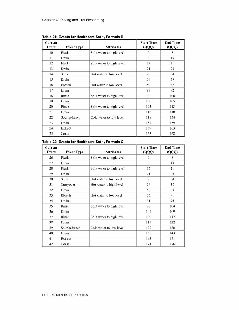
Chapter 4. Testing and Troubleshooting
PELLERIN MILNOR CORPORATION
Table 21: Events for Healthcare Set 1, Formula BCurrentEvent Event Type Attributes
Start Time(QQQ)
End Time(QQQ)
10 Flush Split water to high level 0 811 Drain 8 1312 Flush Split water to high level 13 2113 Drain 21 2614 Suds Hot water to low level 26 5415 Drain 54 5916 Bleach Hot water to low level 59 8717 Drain 87 9218 Rinse Split water to high level 92 10019 Drain 100 10520 Rinse Split water to high level 105 11321 Drain 113 11822 Sour/softener Cold water to low level 118 13423 Drain 134 13924 Extract 139 16325 Coast 163 168
Table 22: Events for Healthcare Set 1, Formula CCurrentEvent Event Type Attributes
Start Time(QQQ)
End Time(QQQ)
26 Flush Split water to high level 0 827 Drain 8 1328 Flush Split water to high level 13 2129 Drain 21 2630 Suds Hot water to low level 26 5431 Carryover Hot water to high level 54 5832 Drain 58 6333 Bleach Hot water to low level 63 9134 Drain 91 9635 Rinse Split water to high level 96 10436 Drain 104 10937 Rinse Split water to high level 109 11738 Drain 117 12239 Sour/softener Cold water to low level 122 13840 Drain 138 14341 Extract 143 17142 Coast 171 176
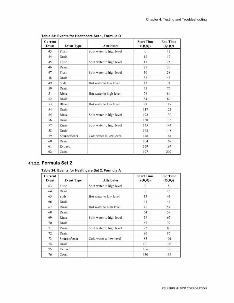
Chapter 4. Testing and Troubleshooting
PELLERIN MILNOR CORPORATION
Table 23: Events for Healthcare Set 1, Formula DCurrentEvent Event Type Attributes
Start Time(QQQ)
End Time(QQQ)
43 Flush Split water to high level 0 1244 Drain 12 1745 Flush Split water to high level 17 2546 Drain 25 3047 Flush Split water to high level 30 3848 Drain 38 4349 Suds Hot water to low level 43 7150 Drain 71 7651 Rinse Hot water to high level 76 8452 Drain 84 8953 Bleach Hot water to low level 89 11754 Drain 117 12255 Rinse Split water to high level 122 13056 Drain 130 13557 Rinse Split water to high level 135 14358 Drain 143 14859 Sour/softener Cold water to low level 148 16460 Drain 164 16961 Extract 169 19762 Coast 197 202
4.3.2.2. Formula Set 2Table 24: Events for Healthcare Set 2, Formula A
CurrentEvent Event Type Attributes
Start Time(QQQ)
End Time(QQQ)
63 Flush Split water to high level 0 864 Drain 8 1365 Suds Hot water to low level 13 4166 Drain 41 4667 Rinse Hot water to high level 46 5468 Drain 54 5969 Rinse Split water to high level 59 6770 Drain 67 7271 Rinse Split water to high level 72 8072 Drain 80 8573 Sour/softener Cold water to low level 85 10174 Drain 101 10675 Extract 106 13076 Coast 130 135
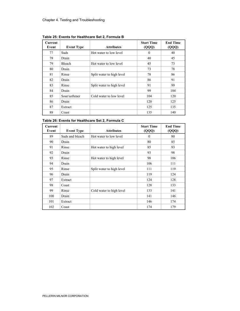
Chapter 4. Testing and Troubleshooting
PELLERIN MILNOR CORPORATION
Table 25: Events for Healthcare Set 2, Formula BCurrentEvent Event Type Attributes
Start Time(QQQ)
End Time(QQQ)
77 Suds Hot water to low level 0 4078 Drain 40 4579 Bleach Hot water to low level 45 7380 Drain 73 7881 Rinse Split water to high level 78 8682 Drain 86 9183 Rinse Split water to high level 91 9984 Drain 99 10485 Sour/softener Cold water to low level 104 12086 Drain 120 12587 Extract 125 13588 Coast 135 140
Table 26: Events for Healthcare Set 2, Formula CCurrentEvent Event Type Attributes
Start Time(QQQ)
End Time(QQQ)
89 Suds and bleach Hot water to low level 0 8090 Drain 80 8591 Rinse Hot water to high level 85 9392 Drain 93 9893 Rinse Hot water to high level 98 10694 Drain 106 11195 Rinse Split water to high level 111 11996 Drain 119 12497 Extract 124 12898 Coast 128 13399 Rinse Cold water to high level 133 141
100 Drain 141 146101 Extract 146 174102 Coast 174 179
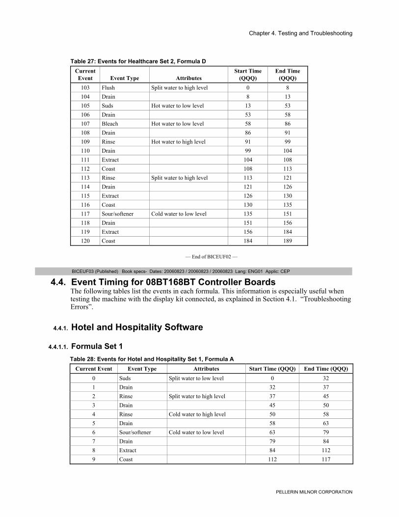
Chapter 4. Testing and Troubleshooting
PELLERIN MILNOR CORPORATION
Table 27: Events for Healthcare Set 2, Formula DCurrentEvent Event Type Attributes
Start Time(QQQ)
End Time(QQQ)
103 Flush Split water to high level 0 8104 Drain 8 13105 Suds Hot water to low level 13 53106 Drain 53 58107 Bleach Hot water to low level 58 86108 Drain 86 91109 Rinse Hot water to high level 91 99110 Drain 99 104111 Extract 104 108112 Coast 108 113113 Rinse Split water to high level 113 121114 Drain 121 126115 Extract 126 130116 Coast 130 135117 Sour/softener Cold water to low level 135 151118 Drain 151 156119 Extract 156 184120 Coast 184 189
— End of BICEUF02 —
BICEUF03 (Published) Book specs- Dates: 20060823 / 20060823 / 20060823 Lang: ENG01 Applic: CEP
4.4. Event Timing for 08BT168BT Controller BoardsThe following tables list the events in each formula. This information is especially useful whentesting the machine with the display kit connected, as explained in Section 4.1. “TroubleshootingErrors”.
4.4.1. Hotel and Hospitality Software
4.4.1.1. Formula Set 1Table 28: Events for Hotel and Hospitality Set 1, Formula A
Current Event Event Type Attributes Start Time (QQQ) End Time (QQQ)0 Suds Split water to low level 0 321 Drain 32 372 Rinse Split water to high level 37 453 Drain 45 504 Rinse Cold water to high level 50 585 Drain 58 636 Sour/softener Cold water to low level 63 797 Drain 79 848 Extract 84 1129 Coast 112 117
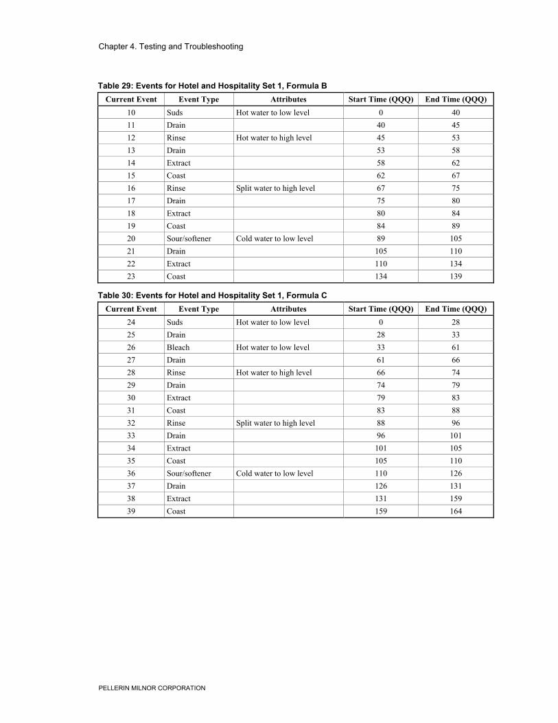
Chapter 4. Testing and Troubleshooting
PELLERIN MILNOR CORPORATION
Table 29: Events for Hotel and Hospitality Set 1, Formula BCurrent Event Event Type Attributes Start Time (QQQ) End Time (QQQ)
10 Suds Hot water to low level 0 4011 Drain 40 4512 Rinse Hot water to high level 45 5313 Drain 53 5814 Extract 58 6215 Coast 62 6716 Rinse Split water to high level 67 7517 Drain 75 8018 Extract 80 8419 Coast 84 8920 Sour/softener Cold water to low level 89 10521 Drain 105 11022 Extract 110 13423 Coast 134 139
Table 30: Events for Hotel and Hospitality Set 1, Formula CCurrent Event Event Type Attributes Start Time (QQQ) End Time (QQQ)
24 Suds Hot water to low level 0 2825 Drain 28 3326 Bleach Hot water to low level 33 6127 Drain 61 6628 Rinse Hot water to high level 66 7429 Drain 74 7930 Extract 79 8331 Coast 83 8832 Rinse Split water to high level 88 9633 Drain 96 10134 Extract 101 10535 Coast 105 11036 Sour/softener Cold water to low level 110 12637 Drain 126 13138 Extract 131 15939 Coast 159 164
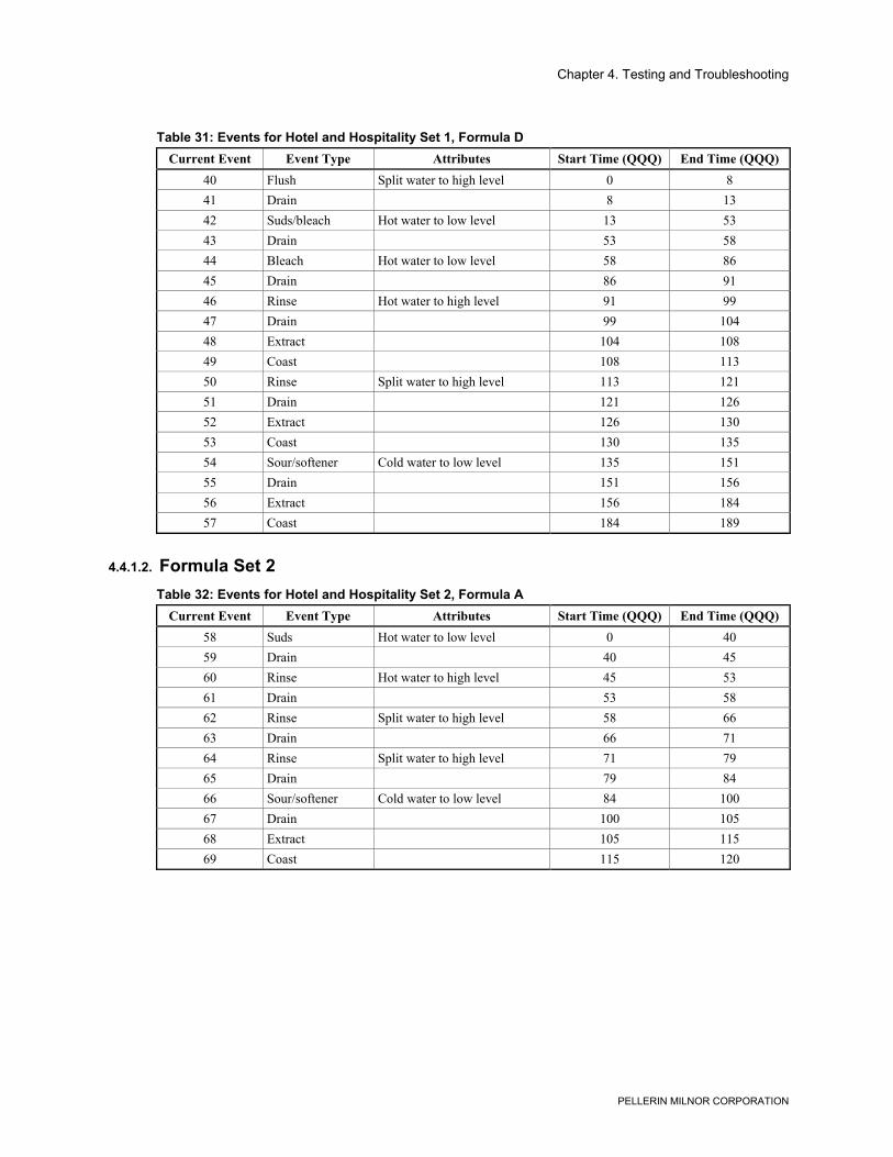
Chapter 4. Testing and Troubleshooting
PELLERIN MILNOR CORPORATION
Table 31: Events for Hotel and Hospitality Set 1, Formula DCurrent Event Event Type Attributes Start Time (QQQ) End Time (QQQ)
40 Flush Split water to high level 0 841 Drain 8 1342 Suds/bleach Hot water to low level 13 5343 Drain 53 5844 Bleach Hot water to low level 58 8645 Drain 86 9146 Rinse Hot water to high level 91 9947 Drain 99 10448 Extract 104 10849 Coast 108 11350 Rinse Split water to high level 113 12151 Drain 121 12652 Extract 126 13053 Coast 130 13554 Sour/softener Cold water to low level 135 15155 Drain 151 15656 Extract 156 18457 Coast 184 189
4.4.1.2. Formula Set 2Table 32: Events for Hotel and Hospitality Set 2, Formula A
Current Event Event Type Attributes Start Time (QQQ) End Time (QQQ)58 Suds Hot water to low level 0 4059 Drain 40 4560 Rinse Hot water to high level 45 5361 Drain 53 5862 Rinse Split water to high level 58 6663 Drain 66 7164 Rinse Split water to high level 71 7965 Drain 79 8466 Sour/softener Cold water to low level 84 10067 Drain 100 10568 Extract 105 11569 Coast 115 120
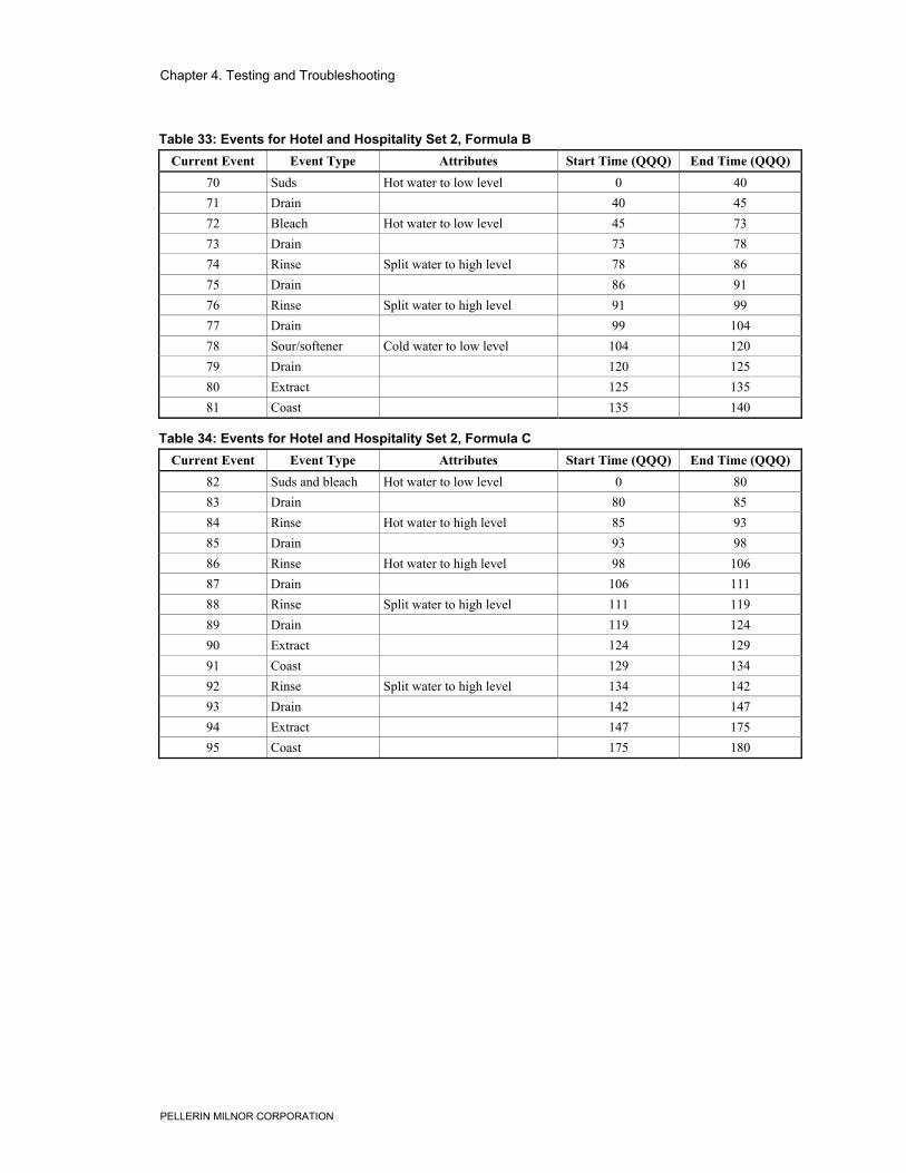
Chapter 4. Testing and Troubleshooting
PELLERIN MILNOR CORPORATION
Table 33: Events for Hotel and Hospitality Set 2, Formula BCurrent Event Event Type Attributes Start Time (QQQ) End Time (QQQ)
70 Suds Hot water to low level 0 4071 Drain 40 4572 Bleach Hot water to low level 45 7373 Drain 73 7874 Rinse Split water to high level 78 8675 Drain 86 9176 Rinse Split water to high level 91 9977 Drain 99 10478 Sour/softener Cold water to low level 104 12079 Drain 120 12580 Extract 125 13581 Coast 135 140
Table 34: Events for Hotel and Hospitality Set 2, Formula CCurrent Event Event Type Attributes Start Time (QQQ) End Time (QQQ)
82 Suds and bleach Hot water to low level 0 8083 Drain 80 8584 Rinse Hot water to high level 85 9385 Drain 93 9886 Rinse Hot water to high level 98 10687 Drain 106 11188 Rinse Split water to high level 111 11989 Drain 119 12490 Extract 124 12991 Coast 129 13492 Rinse Split water to high level 134 14293 Drain 142 14794 Extract 147 17595 Coast 175 180
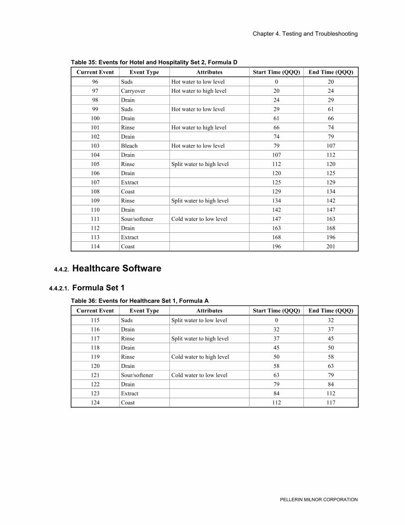
Chapter 4. Testing and Troubleshooting
PELLERIN MILNOR CORPORATION
Table 35: Events for Hotel and Hospitality Set 2, Formula DCurrent Event Event Type Attributes Start Time (QQQ) End Time (QQQ)
96 Suds Hot water to low level 0 2097 Carryover Hot water to high level 20 2498 Drain 24 2999 Suds Hot water to low level 29 61
100 Drain 61 66101 Rinse Hot water to high level 66 74102 Drain 74 79103 Bleach Hot water to low level 79 107104 Drain 107 112105 Rinse Split water to high level 112 120106 Drain 120 125107 Extract 125 129108 Coast 129 134109 Rinse Split water to high level 134 142110 Drain 142 147111 Sour/softener Cold water to low level 147 163112 Drain 163 168113 Extract 168 196114 Coast 196 201
4.4.2. Healthcare Software
4.4.2.1. Formula Set 1Table 36: Events for Healthcare Set 1, Formula A
Current Event Event Type Attributes Start Time (QQQ) End Time (QQQ)115 Suds Split water to low level 0 32116 Drain 32 37117 Rinse Split water to high level 37 45118 Drain 45 50119 Rinse Cold water to high level 50 58120 Drain 58 63121 Sour/softener Cold water to low level 63 79122 Drain 79 84123 Extract 84 112124 Coast 112 117
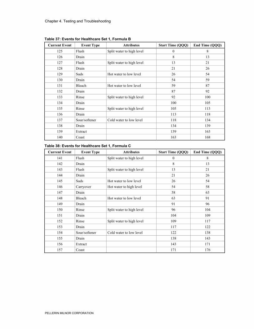
Chapter 4. Testing and Troubleshooting
PELLERIN MILNOR CORPORATION
Table 37: Events for Healthcare Set 1, Formula BCurrent Event Event Type Attributes Start Time (QQQ) End Time (QQQ)
125 Flush Split water to high level 0 8126 Drain 8 13127 Flush Split water to high level 13 21128 Drain 21 26129 Suds Hot water to low level 26 54130 Drain 54 59131 Bleach Hot water to low level 59 87132 Drain 87 92133 Rinse Split water to high level 92 100134 Drain 100 105135 Rinse Split water to high level 105 113136 Drain 113 118137 Sour/softener Cold water to low level 118 134138 Drain 134 139139 Extract 139 163140 Coast 163 168
Table 38: Events for Healthcare Set 1, Formula CCurrent Event Event Type Attributes Start Time (QQQ) End Time (QQQ)
141 Flush Split water to high level 0 8142 Drain 8 13143 Flush Split water to high level 13 21144 Drain 21 26145 Suds Hot water to low level 26 54146 Carryover Hot water to high level 54 58147 Drain 58 63148 Bleach Hot water to low level 63 91149 Drain 91 96150 Rinse Split water to high level 96 104151 Drain 104 109152 Rinse Split water to high level 109 117153 Drain 117 122154 Sour/softener Cold water to low level 122 138155 Drain 138 143156 Extract 143 171157 Coast 171 176
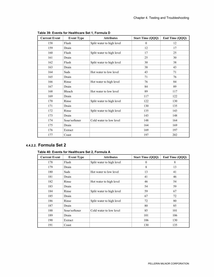
Chapter 4. Testing and Troubleshooting
PELLERIN MILNOR CORPORATION
Table 39: Events for Healthcare Set 1, Formula DCurrent Event Event Type Attributes Start Time (QQQ) End Time (QQQ)
158 Flush Split water to high level 0 12159 Drain 12 17160 Flush Split water to high level 17 25161 Drain 25 30162 Flush Split water to high level 30 38163 Drain 38 43164 Suds Hot water to low level 43 71165 Drain 71 76166 Rinse Hot water to high level 76 84167 Drain 84 89168 Bleach Hot water to low level 89 117169 Drain 117 122170 Rinse Split water to high level 122 130171 Drain 130 135172 Rinse Split water to high level 135 143173 Drain 143 148174 Sour/softener Cold water to low level 148 164175 Drain 164 169176 Extract 169 197177 Coast 197 202
4.4.2.2. Formula Set 2Table 40: Events for Healthcare Set 2, Formula A
Current Event Event Type Attributes Start Time (QQQ) End Time (QQQ)178 Flush Split water to high level 0 8179 Drain 8 13180 Suds Hot water to low level 13 41181 Drain 41 46182 Rinse Hot water to high level 46 54183 Drain 54 59184 Rinse Split water to high level 59 67185 Drain 67 72186 Rinse Split water to high level 72 80187 Drain 80 85188 Sour/softener Cold water to low level 85 101189 Drain 101 106190 Extract 106 130191 Coast 130 135
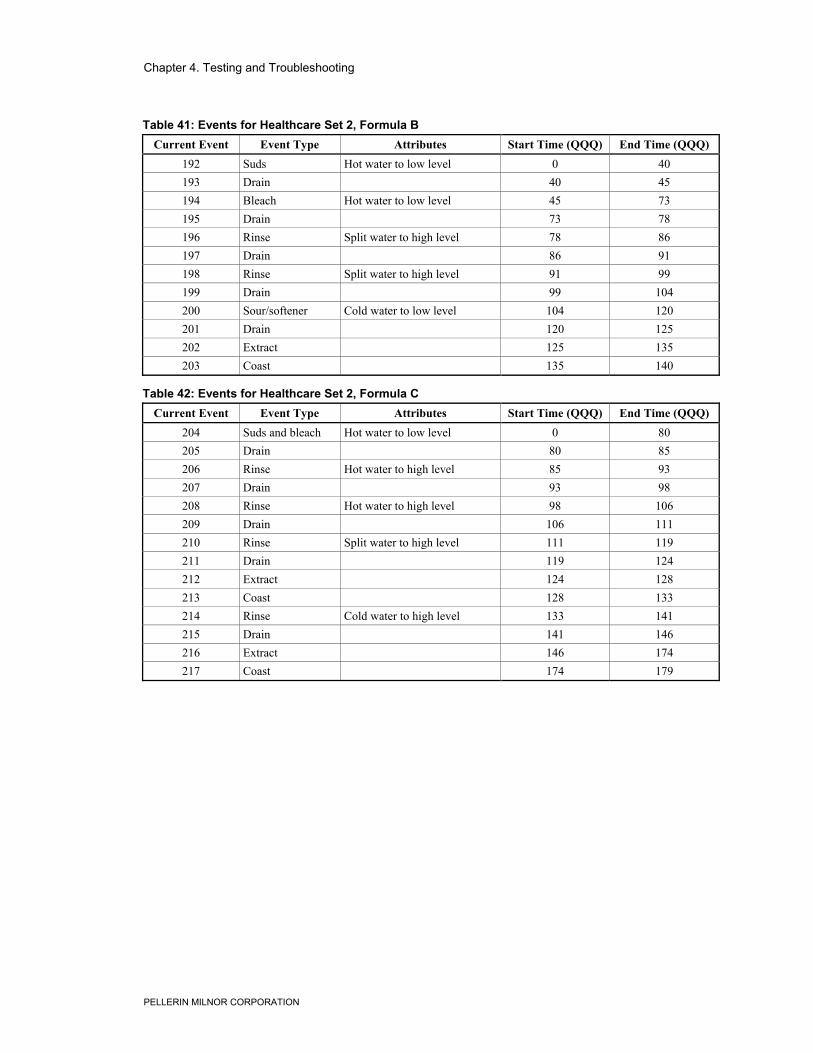
Chapter 4. Testing and Troubleshooting
PELLERIN MILNOR CORPORATION
Table 41: Events for Healthcare Set 2, Formula BCurrent Event Event Type Attributes Start Time (QQQ) End Time (QQQ)
192 Suds Hot water to low level 0 40193 Drain 40 45194 Bleach Hot water to low level 45 73195 Drain 73 78196 Rinse Split water to high level 78 86197 Drain 86 91198 Rinse Split water to high level 91 99199 Drain 99 104200 Sour/softener Cold water to low level 104 120201 Drain 120 125202 Extract 125 135203 Coast 135 140
Table 42: Events for Healthcare Set 2, Formula CCurrent Event Event Type Attributes Start Time (QQQ) End Time (QQQ)
204 Suds and bleach Hot water to low level 0 80205 Drain 80 85206 Rinse Hot water to high level 85 93207 Drain 93 98208 Rinse Hot water to high level 98 106209 Drain 106 111210 Rinse Split water to high level 111 119211 Drain 119 124212 Extract 124 128213 Coast 128 133214 Rinse Cold water to high level 133 141215 Drain 141 146216 Extract 146 174217 Coast 174 179
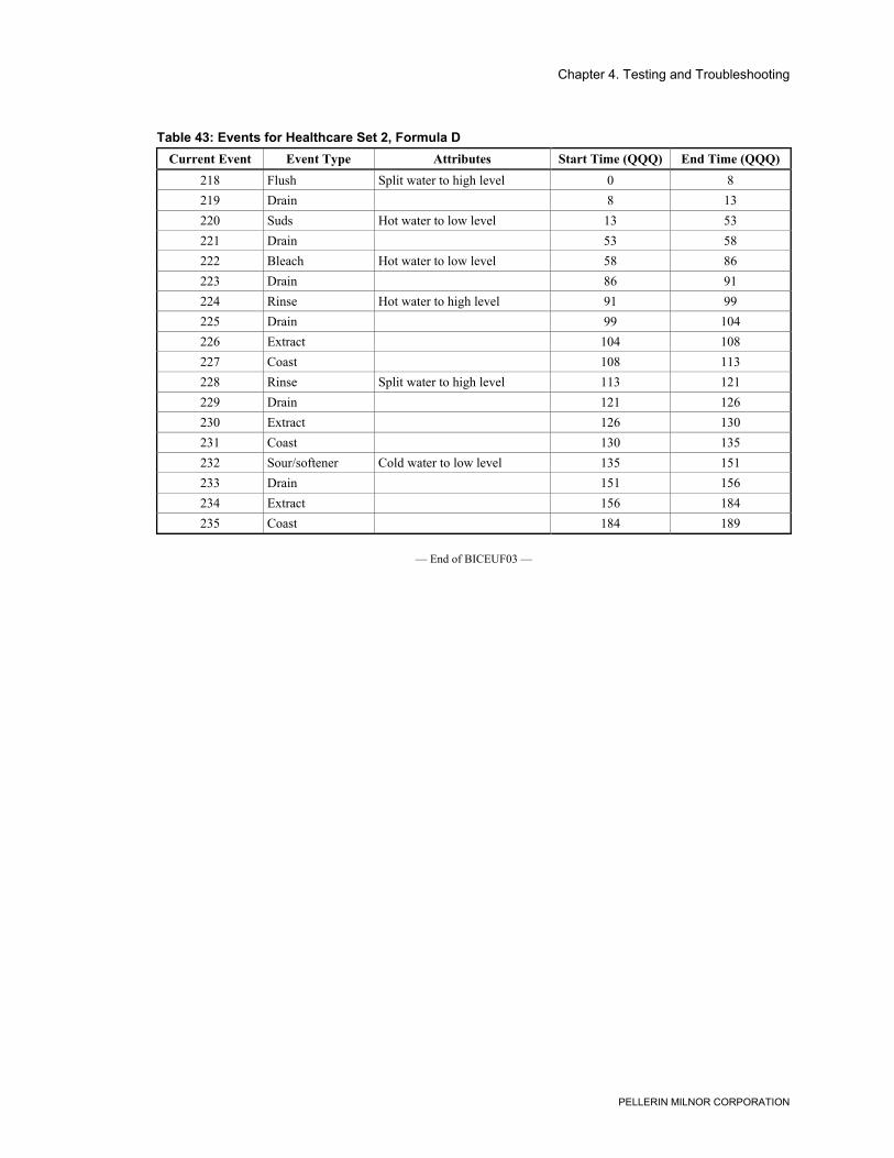
Chapter 4. Testing and Troubleshooting
PELLERIN MILNOR CORPORATION
Table 43: Events for Healthcare Set 2, Formula DCurrent Event Event Type Attributes Start Time (QQQ) End Time (QQQ)
218 Flush Split water to high level 0 8219 Drain 8 13220 Suds Hot water to low level 13 53221 Drain 53 58222 Bleach Hot water to low level 58 86223 Drain 86 91224 Rinse Hot water to high level 91 99225 Drain 99 104226 Extract 104 108227 Coast 108 113228 Rinse Split water to high level 113 121229 Drain 121 126230 Extract 126 130231 Coast 130 135232 Sour/softener Cold water to low level 135 151233 Drain 151 156234 Extract 156 184235 Coast 184 189
— End of BICEUF03 —