Embed Size (px)
Citation preview
General Physics IIGeneral Physics II
By
Dr. Cherdsak Bootjomchai Dr. Cherdsak Bootjomchai (Dr.Per)(Dr.Per)
Chapter 9Chapter 9
Electromagnetic Electromagnetic InductionInduction
Objectives: Objectives: After completing this After completing this module, you should be able to:module, you should be able to:
• Calculate the Calculate the magnitudemagnitude and and directiondirection of the of the induced current or induced current or emfemf in a conductor moving with in a conductor moving with respect to a given respect to a given B-fieldB-field..• Calculate the Calculate the magnetic flux magnetic flux through through an area in a given an area in a given B-fieldB-field..
• Apply Apply Lenz’s lawLenz’s law and the and the right-hand right-hand rulerule to determine directions of to determine directions of induced emf.induced emf.• Describe the operation and use of ac Describe the operation and use of ac and dc and dc generatorsgenerators or or motorsmotors..
Induced CurrentInduced Current
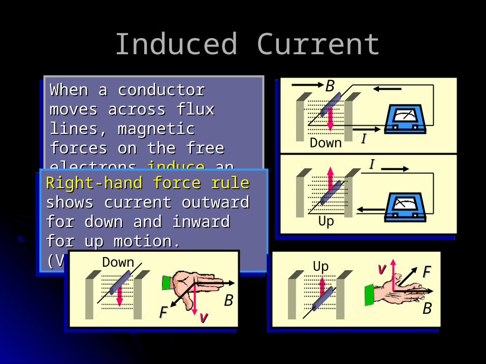
When a conductor moves When a conductor moves across flux lines, across flux lines, magnetic forces on the magnetic forces on the free electrons free electrons induceinduce an an electric current.electric current.
When a conductor moves When a conductor moves across flux lines, across flux lines, magnetic forces on the magnetic forces on the free electrons free electrons induceinduce an an electric current.electric current.
Right-hand force ruleRight-hand force rule shows current outward for shows current outward for down and inward for up down and inward for up motion. (Verify)motion. (Verify)
Right-hand force ruleRight-hand force rule shows current outward for shows current outward for down and inward for up down and inward for up motion. (Verify)motion. (Verify)
Down
II
Down
vvB
FF
Up vv
B
FF
Up
II
B
Induced EMF: ObservationsInduced EMF: ObservationsB Flux lines in
Wb
N turns; velocityv
Faraday’s Law:
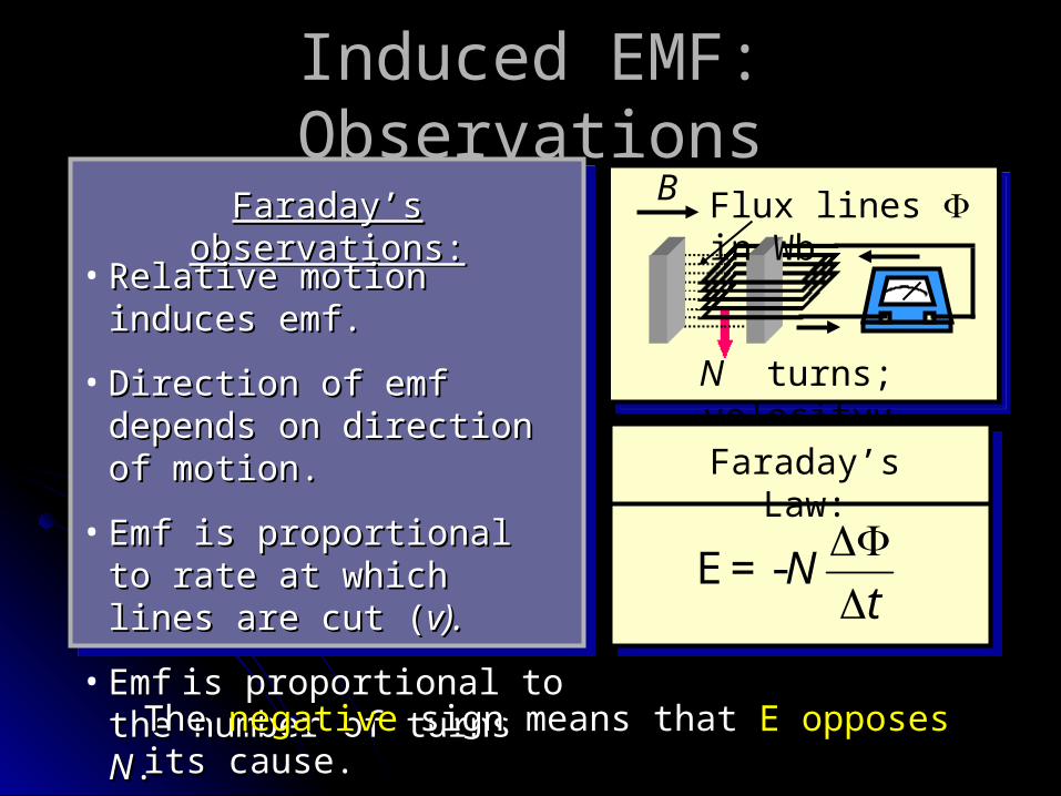
Faraday’s observations:Faraday’s observations:
• Relative motion induces Relative motion induces emf.emf.
• Direction of emf depends Direction of emf depends on direction of motion.on direction of motion.
• Emf is proportional to Emf is proportional to rate at which lines are rate at which lines are cut (cut (v).v).
• EmfEmf is proportional to the is proportional to the number of turns number of turns NN..
-Nt
E=
The The negativenegative sign means that sign means that EE opposes opposes its its cause.cause.
Magnetic Flux DensityMagnetic Flux Density
Magnetic Flux density:
ABA
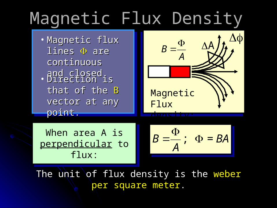
• Magnetic flux Magnetic flux lines lines are are continuous and continuous and closed.closed.
• Direction is that Direction is that of the of the B B vector vector at any point.at any point.
; = B BAA
; = B BA
A
When area A is
perpendicular to flux:
When area A is perpendicular to
flux:
The unit of flux density is the The unit of flux density is the weber per square weber per square metermeter..
Calculating Flux When Area Calculating Flux When Area is Not Perpendicular to Fieldis Not Perpendicular to Field
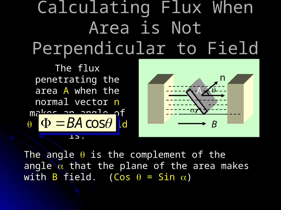
The flux penetrating The flux penetrating the area the area AA when the when the
normal vector normal vector nn makes an angle of makes an angle of with the with the B-fieldB-field is: is:
cosBA cosBA
The angle The angle is the complement of the angle is the complement of the angle that the plane of the area makes with that the plane of the area makes with BB field. field. ((Cos Cos = Sin = Sin ))
nA
B
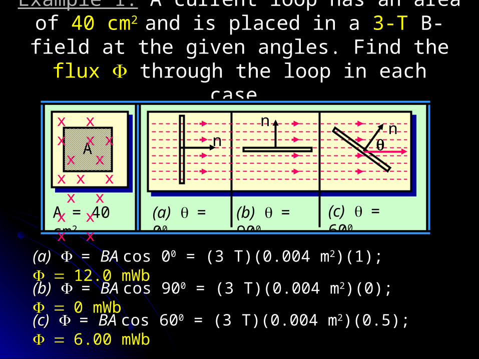
Example 1:Example 1: A current loop has an area of A current loop has an area of 40 cm40 cm22
and is placed in a and is placed in a 3-T3-T B-field at the given angles. B-field at the given angles. Find the Find the fluxflux through the loop in each case. through the loop in each case.
A nnn
A = 40 cm2
(a) = 00
(c) = 600
(b) = 900
x x x x x x x x x x x x x x x x
(a)(a) = = BA BA cos 0cos 000 = (3 T)(0.004 m = (3 T)(0.004 m22)(1); )(1); 12.0 12.0 mWbmWb (b)(b) = = BA BA cos 90cos 9000 = (3 T)(0.004 m = (3 T)(0.004 m22)(0); )(0); 0 0 mWbmWb (c)(c) = = BA BA cos 60cos 6000 = (3 T)(0.004 m = (3 T)(0.004 m22)(0.5); )(0.5); 6.00 6.00 mWbmWb
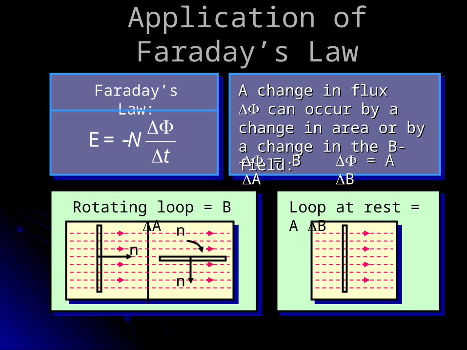
Application of Faraday’s LawApplication of Faraday’s Law
Faraday’s Law:
-Nt
E=
A change in flux A change in flux can can occur by a change in occur by a change in area or by a change in area or by a change in the B-field:the B-field: = B = B AA
= A = A BB
n
n
n
Rotating loop = B A
Loop at rest = A B
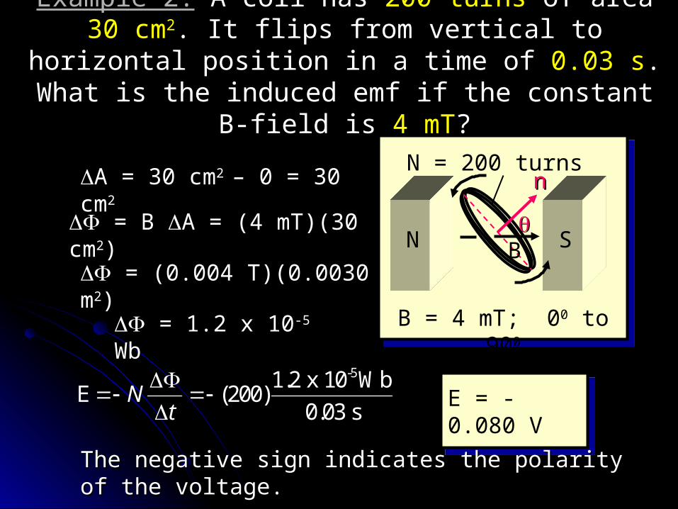
Example 2:Example 2: A coil has A coil has 200 turns200 turns of area of area 30 cm30 cm22. It flips . It flips from vertical to horizontal position in a time of from vertical to horizontal position in a time of 0.03 s0.03 s. .
What is the induced emf if the constant B-field is What is the induced emf if the constant B-field is 4 mT4 mT??
SN
nn
B
N = 200 turns
B = 4 mT; 00 to 900
A = 30 cmA = 30 cm2 2 – 0 = 30 – 0 = 30 cmcm22
= B = B A = (4 mT)(30 A = (4 mT)(30 cmcm22)) = (0.004 T)(0.0030 = (0.004 T)(0.0030 mm22))
= 1.2 x 10= 1.2 x 10⁻⁵-5 WbWb
-51.2 x 10 Wb(200)
0.03 sN
t
E E = -0.080
VE = -0.080 V
The negative sign indicates the polarity of the The negative sign indicates the polarity of the voltage.voltage.
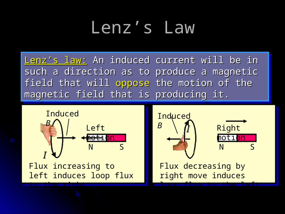
Lenz’s LawLenz’s Law
Lenz’s law:Lenz’s law: An induced current will be in such a An induced current will be in such a direction as to produce a magnetic field that will direction as to produce a magnetic field that will opposeoppose the motion of the magnetic field that is the motion of the magnetic field that is producing it.producing it.
Lenz’s law:Lenz’s law: An induced current will be in such a An induced current will be in such a direction as to produce a magnetic field that will direction as to produce a magnetic field that will opposeoppose the motion of the magnetic field that is the motion of the magnetic field that is producing it.producing it.
Flux decreasing by right move induces loop flux to the left.
N S
Left motion
II
Induced B
Flux increasing to left induces loop flux to the right.
N S
Right motionIIInduced B
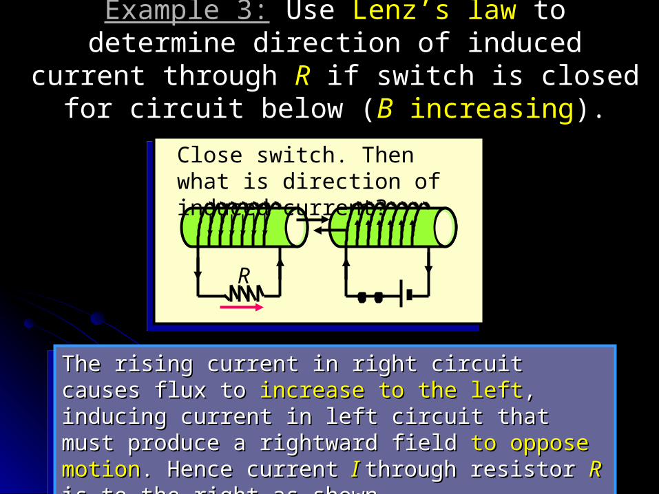
Example 3:Example 3: Use Use Lenz’s lawLenz’s law to determine direction to determine direction of induced current through of induced current through RR if switch is closed for if switch is closed for
circuit below (circuit below (BB increasing increasing).).
R
Close switch. Then what is direction of induced current?
The rising current in right circuit causes flux to The rising current in right circuit causes flux to increase to the leftincrease to the left, inducing current in left , inducing current in left circuit that must produce a rightward field circuit that must produce a rightward field to to oppose motionoppose motion. Hence current . Hence current I I through resistor through resistor RR is to the right as shown. is to the right as shown.
The rising current in right circuit causes flux to The rising current in right circuit causes flux to increase to the leftincrease to the left, inducing current in left , inducing current in left circuit that must produce a rightward field circuit that must produce a rightward field to to oppose motionoppose motion. Hence current . Hence current I I through resistor through resistor RR is to the right as shown. is to the right as shown.
x x x x x x x x x x x x x x x x x x x x x x x x x x x x x x x x x x x x x x x x x x x x x x x x x x x x x x x x x x x x x x x x x x x x x x x x x x x x x x x x x x x x x x x x x x x x x x x x x x x x x x x x x x x x x x
x x x x xx x x x x
Directions of Forces and EMFs
Directions of Forces and EMFs
vL
vI
I
x
BBI
vv
Induced emf
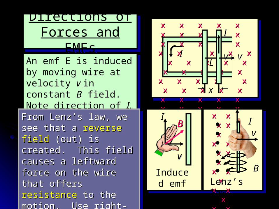
An emf E is induced by moving wire at velocity v in constant B field. Note direction of I.
An emf E is induced by moving wire at velocity v in constant B field. Note direction of I.
From Lenz’s law, we see From Lenz’s law, we see that a that a reverse fieldreverse field (out) (out) is created. This field is created. This field causes a leftward force causes a leftward force on the wire that offers on the wire that offers resistanceresistance to the to the motion. Use right-hand motion. Use right-hand force rule to show this.force rule to show this.
From Lenz’s law, we see From Lenz’s law, we see that a that a reverse fieldreverse field (out) (out) is created. This field is created. This field causes a leftward force causes a leftward force on the wire that offers on the wire that offers resistanceresistance to the to the motion. Use right-hand motion. Use right-hand force rule to show this.force rule to show this.
x x x x x x x x x x x x x x x x x x x x x x x x x x x x x x x x x xx x
B
I
Lenz’s law
v
Motional EMF in a WireMotional EMF in a Wire
L vI
I
x
x x x x x x x x x x x x x x x x x x x x x x x x x x x x x x x x x x x x x x x x x x x
x x x
BBF
vv
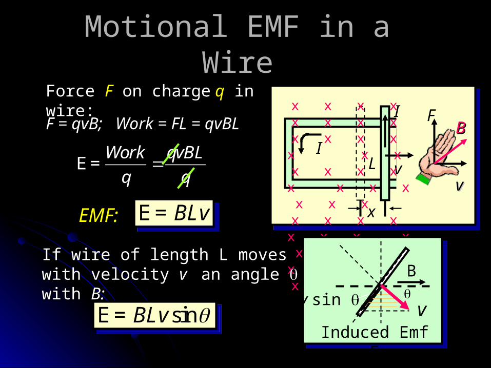
Force Force FF on charge on charge qq in in wire:wire:F = F = qvB;qvB;
Work = FL = Work = FL = qvBLqvBLWork qvBL
q qE=
EMF:EMF: BLvE=BLvE=
If wire of length L moves with If wire of length L moves with velocity velocity v v an angle an angle with with B:B:
Induced Emf E
v sin v
B
sinBLv E= sinBLv E=
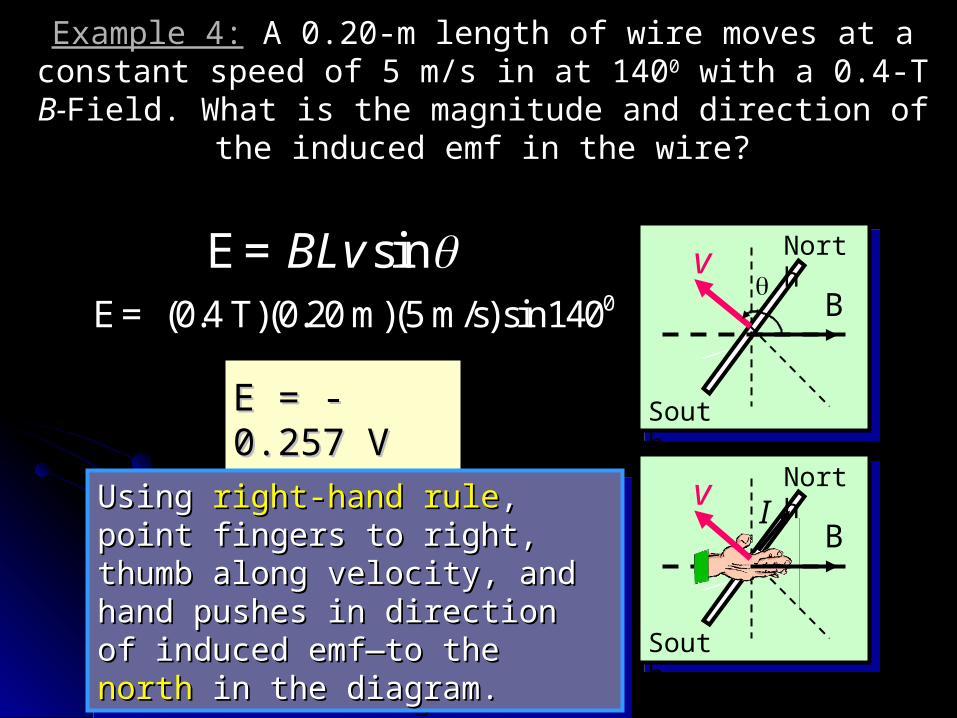
Example 4:Example 4: A 0.20-m length of wire moves at a constant speed A 0.20-m length of wire moves at a constant speed of 5 m/s in at 140of 5 m/s in at 14000 with a 0.4-T with a 0.4-T B-B-Field. What is the magnitude Field. What is the magnitude
and direction of the induced emf in the wire?and direction of the induced emf in the wire?
v
B
North
South
sinBLv E=0 (0.4 T)(0.20 m)(5 m/s)sin140E=
EE = -0.257 = -0.257 VV
Using Using right-hand ruleright-hand rule, point , point fingers to right, thumb along fingers to right, thumb along velocity, and hand pushes in velocity, and hand pushes in direction of induced emf—to direction of induced emf—to the the northnorth in the diagram. in the diagram.
Using Using right-hand ruleright-hand rule, point , point fingers to right, thumb along fingers to right, thumb along velocity, and hand pushes in velocity, and hand pushes in direction of induced emf—to direction of induced emf—to the the northnorth in the diagram. in the diagram.
vB
North
South
I
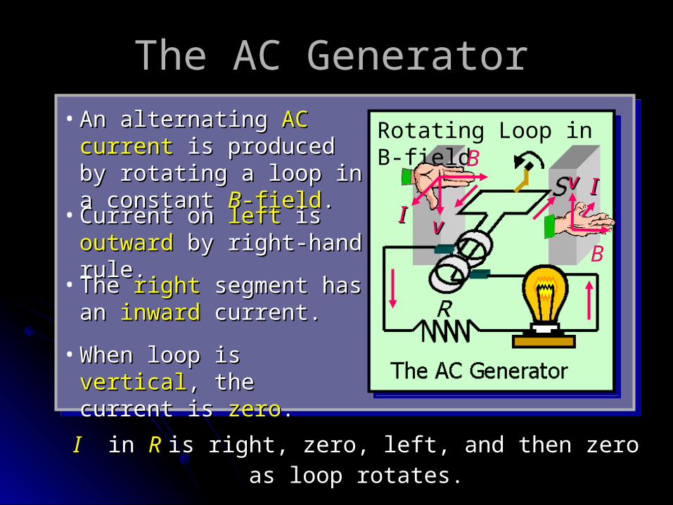
The AC GeneratorThe AC Generator
Rotating Loop in B-field
• An alternating An alternating AC AC currentcurrent is produced by is produced by rotating a loop in a rotating a loop in a constant constant BB-field-field..
• Current on Current on leftleft is is outward outward by right-hand by right-hand rule.rule.
• The The rightright segment has segment has an an inwardinward current. current.
• When loop is When loop is verticalvertical, , the current is the current is zerozero..
vv
B
II
vv
B
II
II in in RR is right, zero, left, and then zero as loop is right, zero, left, and then zero as loop rotates.rotates.
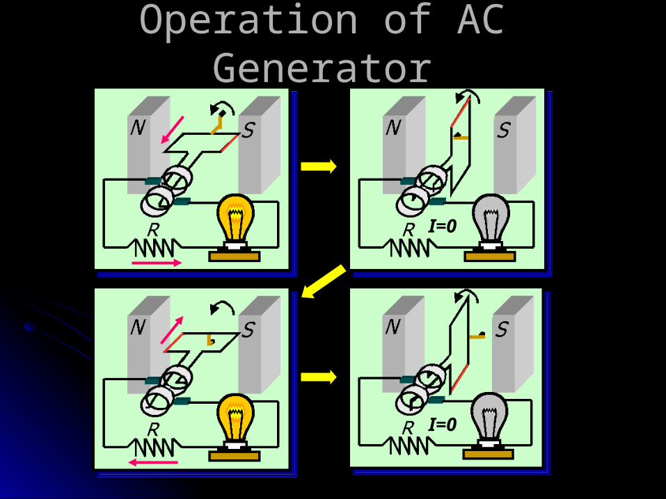
Operation of AC GeneratorOperation of AC Generator
I=0
I=0
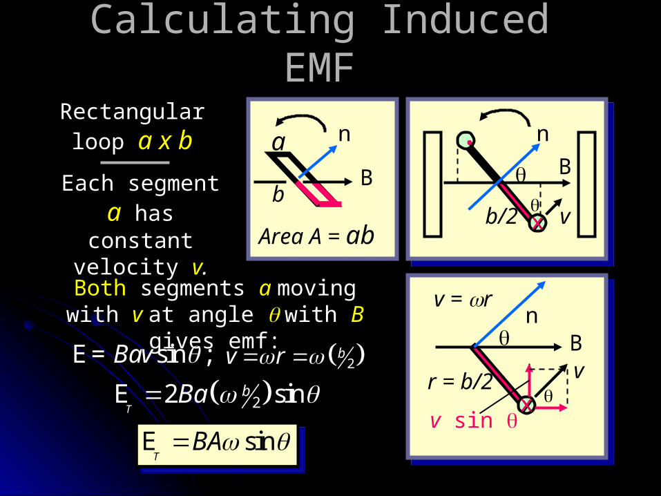
Calculating Induced EMFCalculating Induced EMF
a
b
n
B
Area A = ab
xx
.. n
v
B
b/2
Each segment Each segment aa has constant has constant
velocity velocity vv..
Rectangular Rectangular loop loop a x ba x b
xx
n
vB
r = b/2v sin
v = rBothBoth segments segments aa moving moving with with v v at angle at angle with with BB
gives emf:gives emf:sin ;Bav E= 2
bv r
22 sinT
bBa E
sinT
BA E sinT
BA E
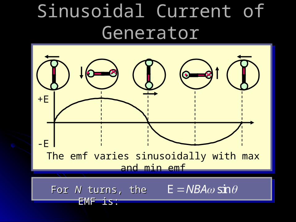
Sinusoidal Current of GeneratorSinusoidal Current of Generator
The emf varies sinusoidally with max and min emf
+E
-E
sinNBA EFor For NN turns, the EMF is: turns, the EMF is:
xx.. xx..
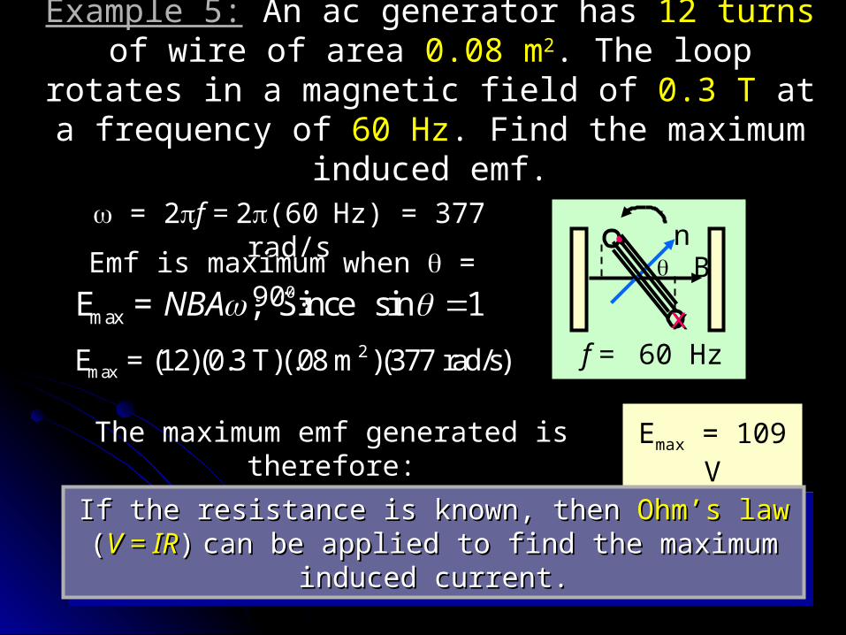
Example 5:Example 5: An ac generator has An ac generator has 12 turns12 turns of wire of of wire of area area 0.08 m0.08 m22. The loop rotates in a magnetic field of . The loop rotates in a magnetic field of
0.3 T0.3 T at a frequency of at a frequency of 60 Hz60 Hz. Find the maximum . Find the maximum induced emf.induced emf.
xx
.. nB
f = 60 Hz
= 2= 2f = f = 22(60(60Hz) = 377 Hz) = 377 rad/srad/s
max ; Since sin 1NBA E =2
max (12)(0.3 T)(.08 m )(377 rad/s)E =
Emf is maximum when Emf is maximum when = = 909000..
The maximum emf generated is The maximum emf generated is therefore:therefore:
Emax = 109 V
If the resistance is known, then If the resistance is known, then Ohm’s lawOhm’s law ( (V = IRV = IR)) can be applied to find the maximum induced can be applied to find the maximum induced
current.current.
If the resistance is known, then If the resistance is known, then Ohm’s lawOhm’s law ( (V = IRV = IR)) can be applied to find the maximum induced can be applied to find the maximum induced
current.current.
The DC GeneratorThe DC Generator
DC Generator
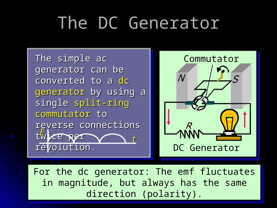
The simple ac The simple ac generator can be generator can be converted to a converted to a dc dc generatorgenerator by using a by using a single single split-ring split-ring commutatorcommutator to reverse to reverse connections twice per connections twice per revolution.revolution.
Commutator
For the dc generator: The emf fluctuates in magnitude, but always has the same direction
(polarity).
For the dc generator: The emf fluctuates in magnitude, but always has the same direction
(polarity).
ttEE
The Electric MotorThe Electric Motor
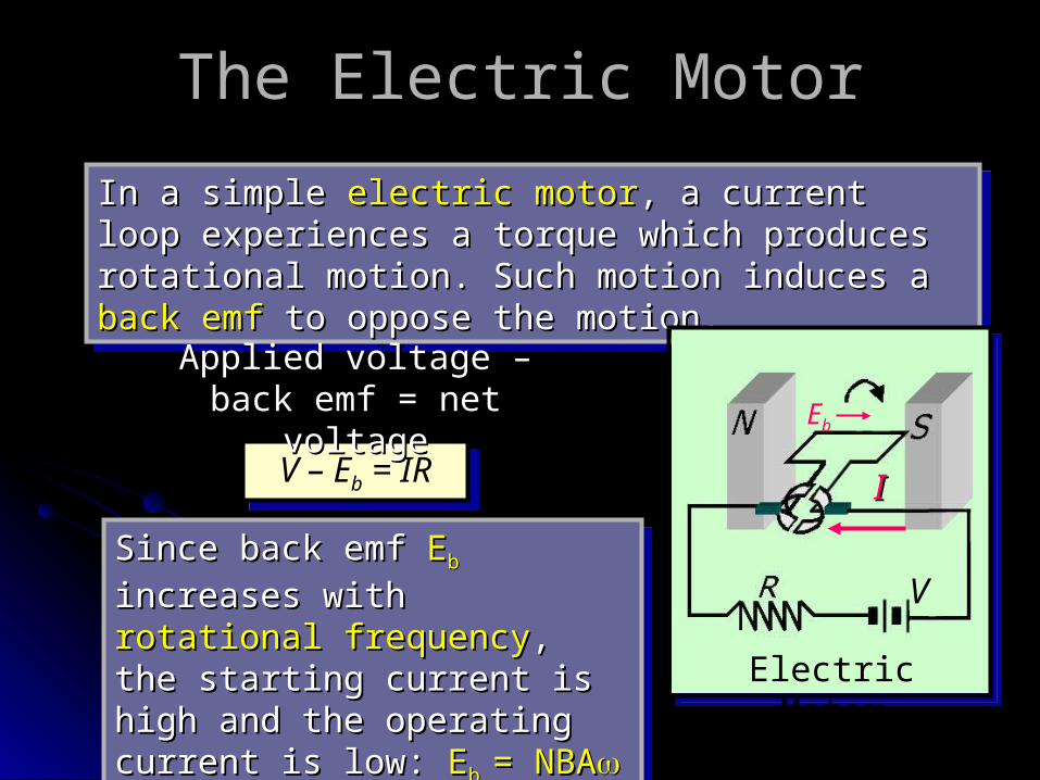
In a simple In a simple electric motorelectric motor, a current loop , a current loop experiences a torque which produces rotational experiences a torque which produces rotational motion. Such motion induces a motion. Such motion induces a back emfback emf to to oppose the motion.oppose the motion.
In a simple In a simple electric motorelectric motor, a current loop , a current loop experiences a torque which produces rotational experiences a torque which produces rotational motion. Such motion induces a motion. Such motion induces a back emfback emf to to oppose the motion.oppose the motion.
Electric Motor
V
V – Eb = IRV – Eb = IR
Applied voltage – back Applied voltage – back emf = net voltageemf = net voltage
Since back emf Since back emf EEbb increases increases with with rotational frequencyrotational frequency, , the starting current is high the starting current is high and the operating current is and the operating current is low: low: EEb b = NBA= NBA sin sin
Since back emf Since back emf EEbb increases increases with with rotational frequencyrotational frequency, , the starting current is high the starting current is high and the operating current is and the operating current is low: low: EEb b = NBA= NBA sin sin
Eb
II
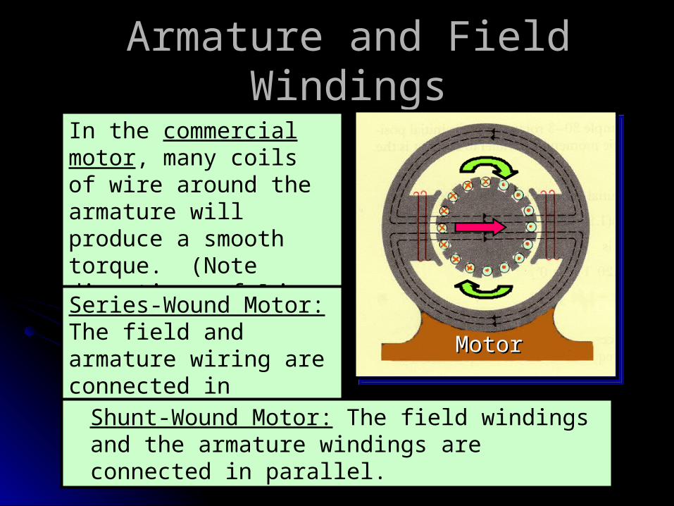
Armature and Field WindingsArmature and Field Windings
In the commercial motor, many coils of wire around the armature will produce a smooth torque. (Note directions of I in wires.)Series-Wound Motor: The field and armature wiring are connected in series.
MotorMotor
Shunt-Wound Motor: The field windings and the armature windings are connected in parallel.
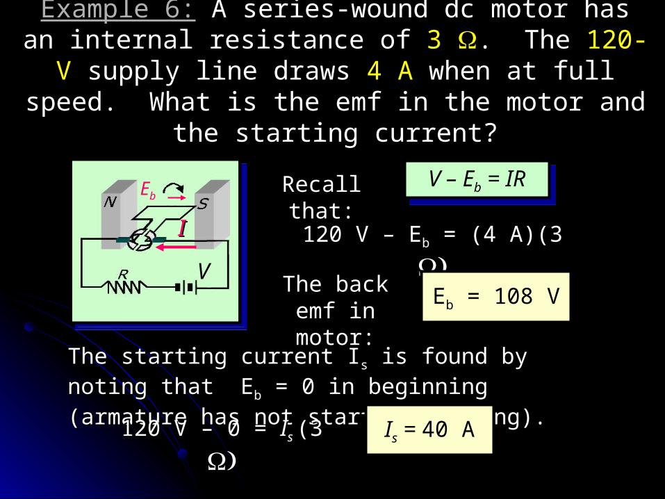
Example 6:Example 6: A series-wound dc motor has an internal A series-wound dc motor has an internal resistance of resistance of 3 3 . The . The 120-V120-V supply line draws supply line draws 4 A4 A
when at full speed. What is the emf in the motor and when at full speed. What is the emf in the motor and the starting current?the starting current?
V
Eb
II
V – Eb = IRV – Eb = IRRecall that:Recall that:
120 V – 120 V – EEbb = (4 A)(3 = (4 A)(3
Eb = 108 VThe back The back emf in emf in motor:motor:
The starting current IThe starting current Iss is found by noting that is found by noting that EEbb = 0 in beginning (armature has not started = 0 in beginning (armature has not started rotating).rotating).
120 V – 0 = 120 V – 0 = IIs s (3 (3 Is = 40 A
SummarySummary
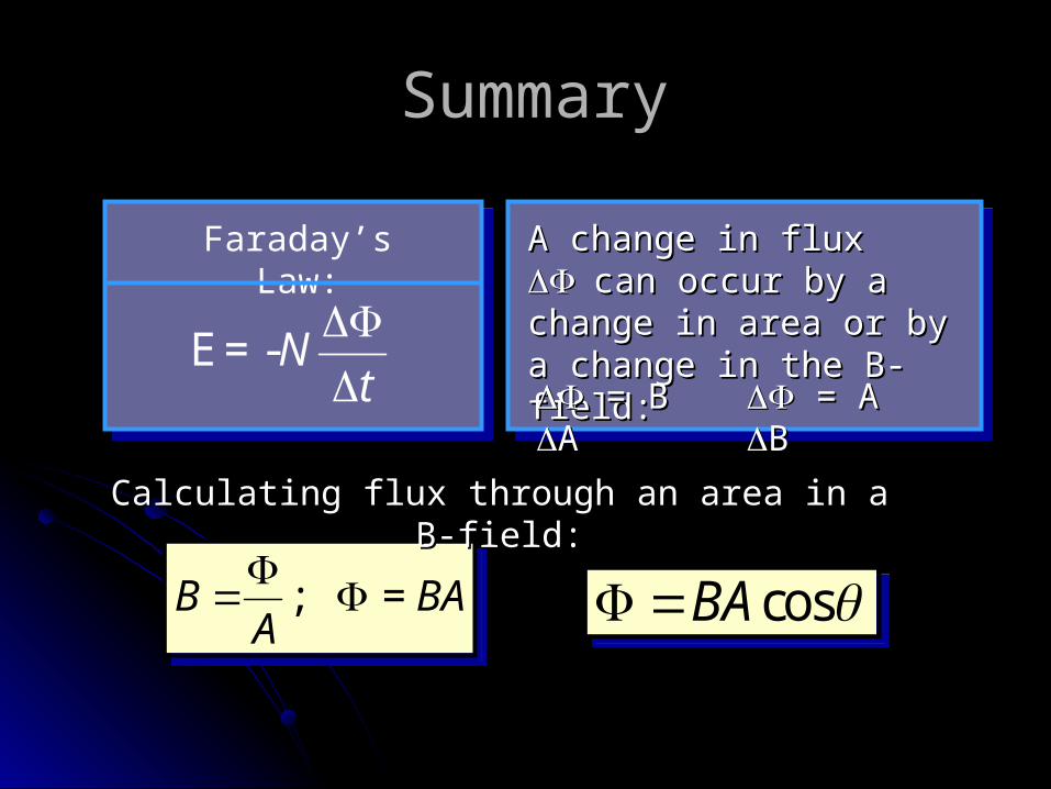
Faraday’s Law:
-Nt
E=
A change in flux A change in flux can can occur by a change in occur by a change in area or by a change in area or by a change in the B-field:the B-field: = B = B AA
= A = A BB
cosBA cosBA ; = B BAA
; = B BA
A
Calculating flux through an area in a B-field:Calculating flux through an area in a B-field:
Summary (Cont.)Summary (Cont.)
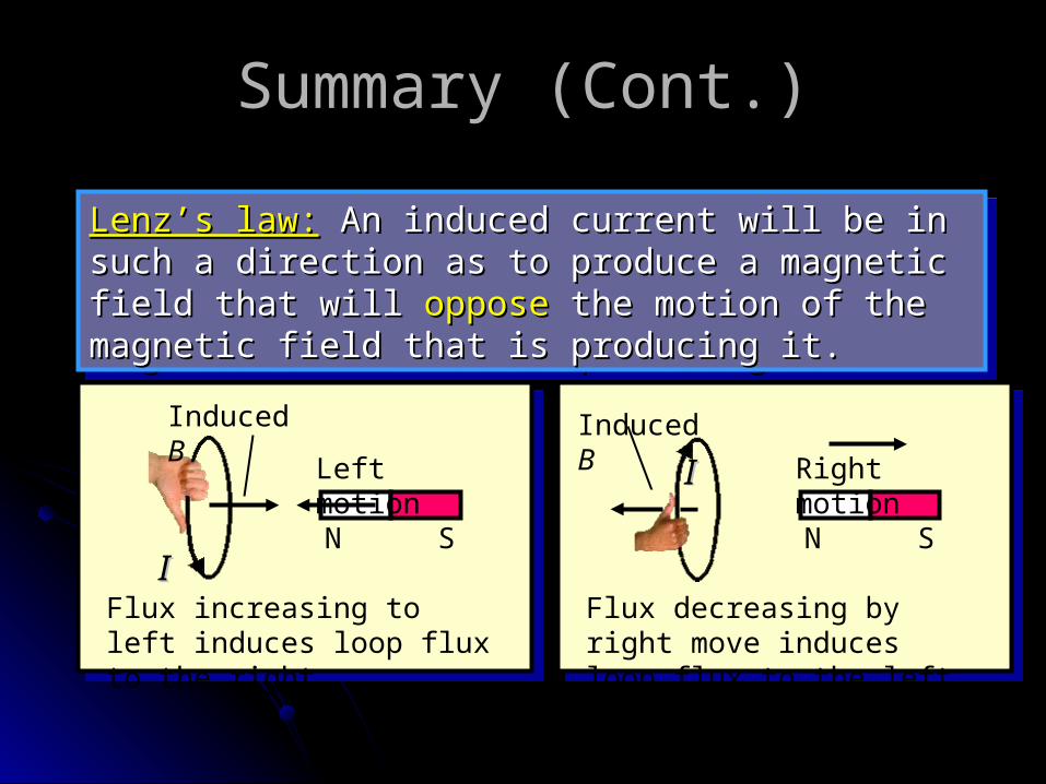
Lenz’s law:Lenz’s law: An induced current will be in such a An induced current will be in such a direction as to produce a magnetic field that will direction as to produce a magnetic field that will opposeoppose the motion of the magnetic field that is the motion of the magnetic field that is producing it.producing it.
Lenz’s law:Lenz’s law: An induced current will be in such a An induced current will be in such a direction as to produce a magnetic field that will direction as to produce a magnetic field that will opposeoppose the motion of the magnetic field that is the motion of the magnetic field that is producing it.producing it.
Flux decreasing by right move induces loop flux to the left.
N S
Left motion
II
Induced B
Flux increasing to left induces loop flux to the right.
N S
Right motionIIInduced B
Summary (Cont.)Summary (Cont.)
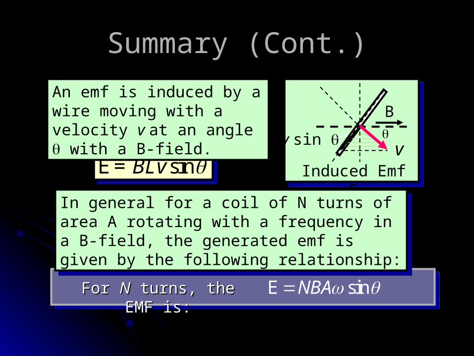
sinBLv E= sinBLv E= Induced Emf E
v sin v
BAn emf is induced by a wire moving with a velocity v at an angle with a B-field.
sinNBA EFor For NN turns, the EMF is: turns, the EMF is:
In general for a coil of N turns of area A rotating with a frequency in a B-field, the generated emf is given by the following relationship:
In general for a coil of N turns of area A rotating with a frequency in a B-field, the generated emf is given by the following relationship:
Summary (Cont.)Summary (Cont.)
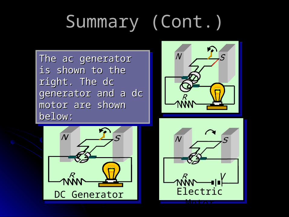
DC Generator Electric Motor
V
The ac generator is The ac generator is shown to the right. shown to the right. The dc generator and The dc generator and a dc motor are shown a dc motor are shown below:below:
The ac generator is The ac generator is shown to the right. shown to the right. The dc generator and The dc generator and a dc motor are shown a dc motor are shown below:below:
Summary (Cont.)Summary (Cont.)
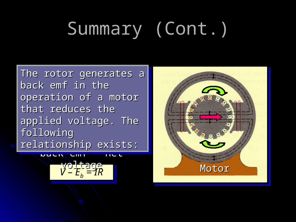
V – Eb = IRV – Eb = IR
Applied voltage – back Applied voltage – back emf = net voltageemf = net voltage
The rotor generates a The rotor generates a back emf in the back emf in the operation of a motor operation of a motor that reduces the applied that reduces the applied voltage. The following voltage. The following relationship exists:relationship exists:
The rotor generates a The rotor generates a back emf in the back emf in the operation of a motor operation of a motor that reduces the applied that reduces the applied voltage. The following voltage. The following relationship exists:relationship exists:
MotorMotor
Summary (Cont.)Summary (Cont.)
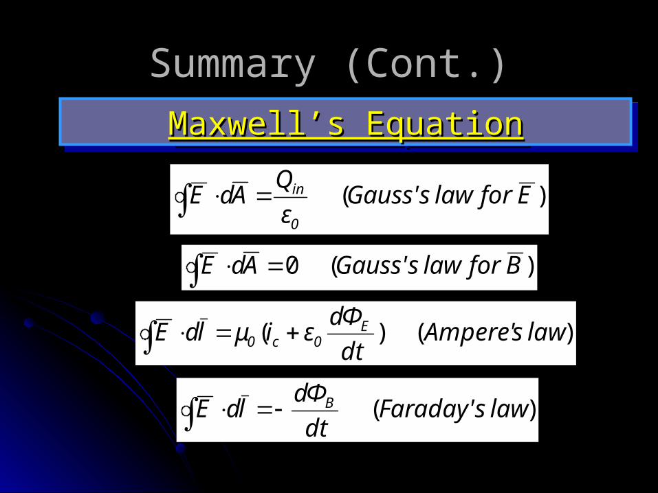
Maxwell’s EquationMaxwell’s EquationMaxwell’s EquationMaxwell’s Equation
)( EforlawsGauss'ε
QAdE
0
in
)(0 BforlawsGauss'AdE
)()( lawsAmpere'dt
dΦεiμldE E
0c0
)( lawsFaraday'dt
dΦldE B
The end of Chapter The end of Chapter 99
Electromagnetic Electromagnetic InductionInduction