Embed Size (px)
Citation preview
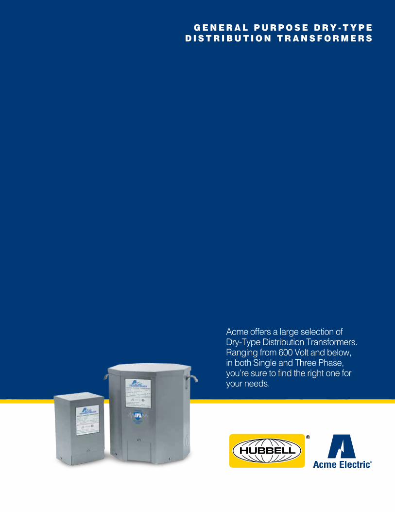
G E N E R A L P U R P O S E D R Y - T Y P E D I S T R I B U T I O N T R A N S F O R M E R S
Acme offers a large selection of Dry-Type Distribution Transformers. Ranging from 600 Volt and below, in both Single and Three Phase, you’re sure to find the right one for your needs.

2
GENERAL PURPOSE TRANSFORMERS: THE BASICS
What is a transformer and how does it work? A transformer is an electrical apparatus designed to convert alternating current from one voltage to another. It can be designed to “step up” or “step down” voltages and works on the magnetic induction principle. A transformer has no moving parts and is a completely static solid state device, which insures, under normal operating conditions, a long and trouble-free life. It consists, in its simplest form, of two or more coils of insulated wire wound on a laminated steel core. When voltage is introduced to one coil, called the primary, it magnetizes the iron core. A voltage is then induced in the other coil, called the secondary or output coil. The change of voltage (or voltage ratio) between the primary and secondary depends on the turns ratio of the two coils.
Can transformers be operated at voltages other than nameplate voltages? In some cases, transformers can be operated at voltages below the nameplate rated voltage. In NO case should a transformer be operated at a voltage in excess of its nameplate rating, unless taps are provided for this purpose. When operating below the rated voltage, the kVA capacity is reduced correspondingly. For example, if a 480 volt primary transformer with a 240 volt secondary is operated at 240 volts, the secondary voltage is reduced to 120 volts. If the transformer was originally rated 10 kVA, the reduced rating would be 5 kVA, or in direct proportion to the applied voltage.
Can Single Phase Transformers be used for Three Phase applications? Yes. Three phase transformers are sometimes not readily available whereas single phase transformers can generally be found in stock. Three single phase transformers can be used in delta connected primary and wye or delta connected secondary. They should never be connected wye primary to wye secondary, since this will result in unstable secondary voltage. The equivalent three phase capacity when properly connected of three single phase transformers is three times the nameplate rating of each single phase transformer. For example: Three 10 kVA single phase transformers will accommodate a 30 kVA three phase load.
What are typical applications for transfomers?ACME transformers should be specified to: (1) Distribute power at high voltage. (2) Eliminate double wiring. (3) Operate 120 volt equipment from power circuits. (4) Insulate circuits/establish separately derived circuits. (5) Provide 3-wire secondary circuits. (6) Buck and Boost (7) Provide electrostatic shielding for transient noise protection.
For more information,visit our catalog or our website www.hubbell-acmeelectric.com
ENCAPSULATED Single Phase, .05 to .150 kVA Featuresn UL listed, CSA certified and UL-3R enclosure meets or exceeds all listing criteria including NEMA, ANSI and OSHA
standards.n Easy and convenient installation to meet your re quirements, the transformer can be mounted in any position.n Long Life UL class 130°C insulation system. Transformers can be banked for three phase service.n Large wiring compartment, no conduit or pull boxes required. Front access for wiring ease. Wiring compartment remains cool.n Completely enclosed UL-3R enclosure for indoor/outdoor service. Rugged non-ventilated construction.n Plenty of knockouts for multi-directional entry.n All copper lead wire terminations.n Ground studs for use with non-metallic conduit.
ENCAPSULATED Single Phase, .250 to 25 kVA
n Installation keyhole mounting slots for mounting bolts prior to installation. Mounting slots are accessible from the front. Lifting ears are included on 3 to 25 kVA units.
n Wiring flexible copper leadwire terminations for easy connections outside the front access wiring compartment. Dual size knockouts in both sides and the bottom of the wiring compartment for greater wiring convenience and flexibility.
3
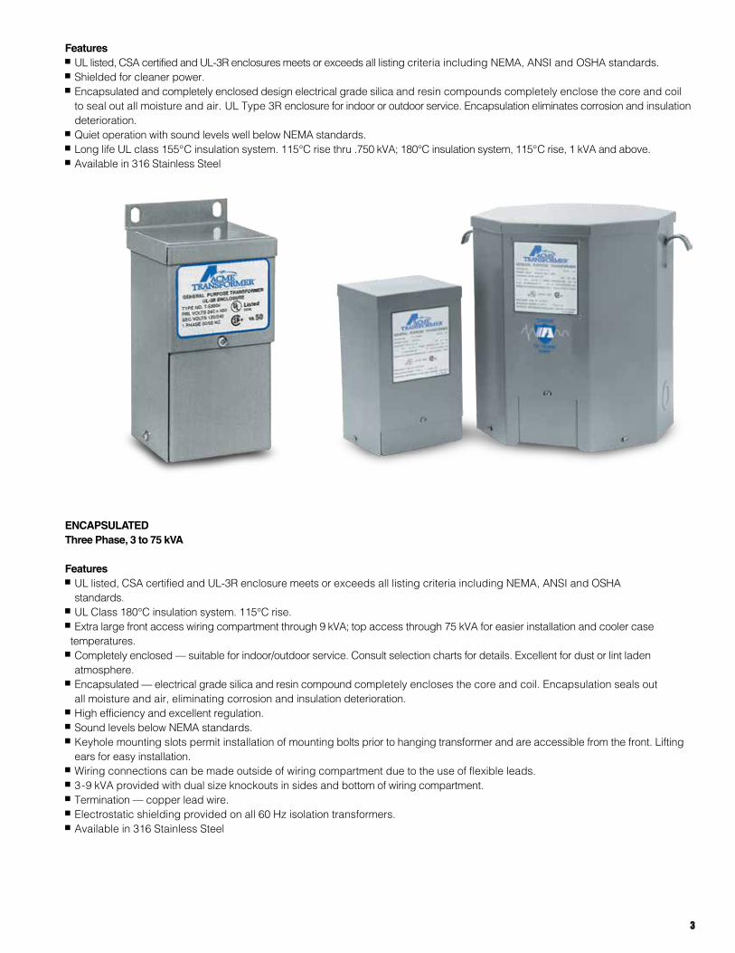
Featuresn UL listed, CSA certified and UL-3R enclosures meets or exceeds all listing criteria including NEMA, ANSI and OSHA standards.n Shielded for cleaner power.n Encapsulated and completely enclosed design electrical grade silica and resin compounds completely enclose the core and coil
to seal out all moisture and air. UL Type 3R enclosure for indoor or outdoor service. Encapsulation eliminates corrosion and insulation deterioration.
n Quiet operation with sound levels well below NEMA standards.n Long life UL class 155°C insulation system. 115°C rise thru .750 kVA; 180°C insulation system, 115°C rise, 1 kVA and above.n Available in 316 Stainless Steel
ENCAPSULATED Three Phase, 3 to 75 kVA
Featuresn UL listed, CSA certified and UL-3R enclosure meets or exceeds all listing criteria including NEMA, ANSI and OSHA standards.
n UL Class 180°C insulation system. 115°C rise.n Extra large front access wiring compartment through 9 kVA; top access through 75 kVA for easier installation and cooler case temperatures.
n Completely enclosed — suitable for indoor/outdoor service. Consult selection charts for details. Excellent for dust or lint laden atmosphere.
n Encapsulated — electrical grade silica and resin compound completely encloses the core and coil. Encapsulation seals out all moisture and air, eliminating corrosion and insulation deterioration.
n High efficiency and excellent regulation.n Sound levels below NEMA standards.n Keyhole mounting slots permit installation of mounting bolts prior to hanging transformer and are accessible from the front. Lifting
ears for easy installation.n Wiring connections can be made outside of wiring compartment due to the use of flexible leads.n 3-9 kVA provided with dual size knockouts in sides and bottom of wiring compartment.n Termination — copper lead wire.n Electrostatic shielding provided on all 60 Hz isolation transformers.n Available in 316 Stainless Steel
4
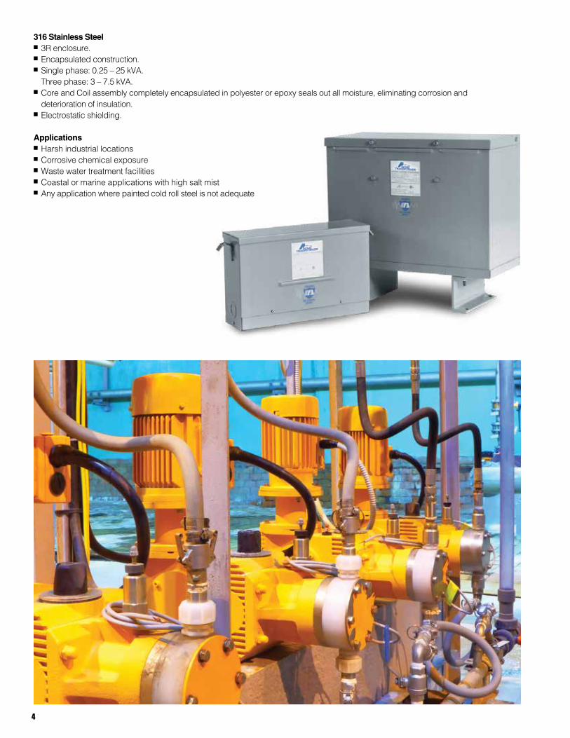
316 Stainless Steel n 3R enclosure.n Encapsulated construction.n Single phase: 0.25 – 25 kVA. Three phase: 3 – 7.5 kVA.n Core and Coil assembly completely encapsulated in polyester or epoxy seals out all moisture, eliminating corrosion and deterioration of insulation.n Electrostatic shielding.
Applicationsn Harsh industrial locationsn Corrosive chemical exposuren Waste water treatment facilitiesn Coastal or marine applications with high salt mistn Any application where painted cold roll steel is not adequate
5
VENTILATED Single Phase 37.5 to 250 kVA, Three Phase 15 to 1000 kVA
Featuresn With weather shield, UL Type 3R enclosure or Type 2 enclosure without weather shield. UL listed and CSA certified.n UL Class 220°C insulation system, 150°C rise.n Extra large wiring compartment for easier installation and cooler case temperatures.n NEMA standard bus bar terminals, no special tools needed to make clearly marked connections. Tap changing easily
accomplished with jumpers.n Aluminum windings for increased insulation life, cooler operation, lower losses.n Noise and vibration isolating pads standard to assure quiet operation.n Large permanently legible nameplates on front.n Single phase units can be banked for 3 phase service.n All units have ground studs for use with non-metallic conduit.n Suitable for wall or “trapeze” mounting. Wall brackets are available for units up to 50 kVA single and 75 kVA three phase.n Other models are available with class 220°C insulation and either 115°C or 80°C rise operating temperature. n Three phase units15-112.5 kVA have pre-installed lugs.
DOEThree Phase 15 to 1000 kVA
Our new line of general purpose transformers not only meets but exceeds the new, more stringent DOE 2016 Energy Efficiency Standards.
Designed with feedback from our customers, the line is fully compatible in size with comparable transformers meeting the old 2007 TP-1 standards.
Replacing older general purpose transformers with our DOE 2016 compliant equipment will result in increased profitability from lower operating costs as well as a positive impact on the environment from a reduced carbon footprint.
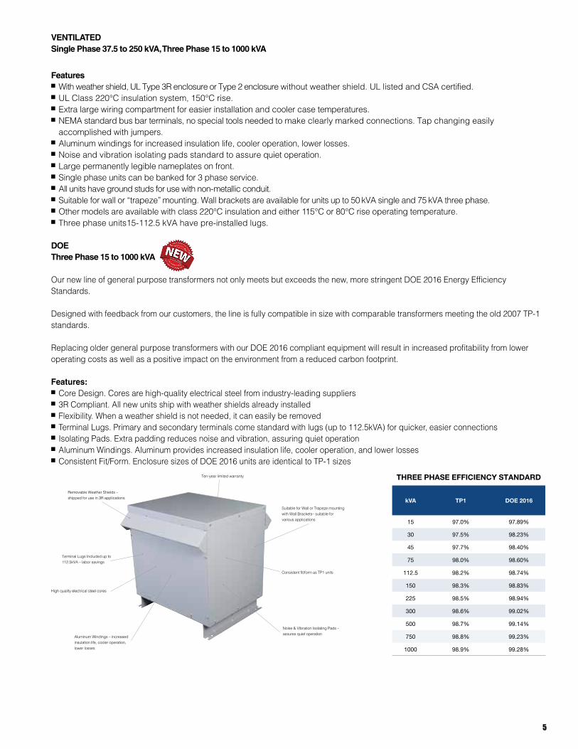
Features: n Core Design. Cores are high-quality electrical steel from industry-leading suppliersn 3R Compliant. All new units ship with weather shields already installedn Flexibility. When a weather shield is not needed, it can easily be removedn Terminal Lugs. Primary and secondary terminals come standard with lugs (up to 112.5kVA) for quicker, easier connections n Isolating Pads. Extra padding reduces noise and vibration, assuring quiet operationn Aluminum Windings. Aluminum provides increased insulation life, cooler operation, and lower lossesn Consistent Fit/Form. Enclosure sizes of DOE 2016 units are identical to TP-1 sizes
Ten-year limited warranty
Removable Weather Shields – shipped for use in 3R applications
Terminal Lugs Included up to 112.5kVA – labor savings
High quality electrical steel cores
Aluminum Windings – increased insulation life, cooler operation, lower losses
Suitable for Wall or Trapeze mounting with Wall Brackets– suitable for various applications
Consistent fit/form as TP1 units
Noise & Vibration Isolating Pads – assures quiet operation
THREE PHASE EFFICIENCY STANDARD
kVA TP1 DOE 2016
15 97.0% 97.89%
30 97.5% 98.23%
45 97.7% 98.40%
75 98.0% 98.60%
112.5 98.2% 98.74%
150 98.3% 98.83%
225 98.5% 98.94%
300 98.6% 99.02%
500 98.7% 99.14%
750 98.8% 99.23%
1000 98.9% 99.28%
6
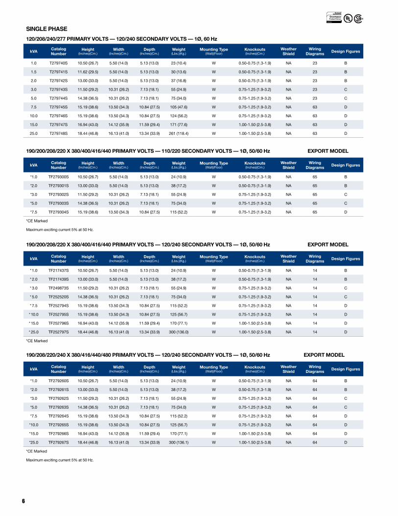
SINGLE PHASE
120/208/240/277 PRIMARY VOLTS — 120/240 SECONDARY VOLTS — 1Ø, 60 Hz
kVACatalog Number
Height (Inches)(Cm.)
Width (Inches)(Cm.)
Depth (Inches)(Cm.)
Weight (Lbs.)(Kg.)
Mounting Type(Wall)(Floor)
Knockouts (Inches)(Cm.)
Weather Shield
Wiring Diagrams
Design Figures
1.0 T279740S 10.50 (26.7) 5.50 (14.0) 5.13 (13.0) 23 (10.4) W 0.50-0.75 (1.3-1.9) NA 23 B
1.5 T279741S 11.62 (29.5) 5.50 (14.0) 5.13 (13.0) 30 (13.6) W 0.50-0.75 (1.3-1.9) NA 23 B
2.0 T279742S 13.00 (33.0) 5.50 (14.0) 5.13 (13.0) 37 (16.8) W 0.50-0.75 (1.3-1.9) NA 23 B
3.0 T279743S 11.50 (29.2) 10.31 (26.2) 7.13 (18.1) 55 (24.9) W 0.75-1.25 (1.9-3.2) NA 23 C
5.0 T279744S 14.38 (36.5) 10.31 (26.2) 7.13 (18.1) 75 (34.0) W 0.75-1.25 (1.9-3.2) NA 23 C
7.5 T279745S 15.19 (38.6) 13.50 (34.3) 10.84 (27.5) 105 (47.6) W 0.75-1.25 (1.9-3.2) NA 63 D
10.0 T279746S 15.19 (38.6) 13.50 (34.3) 10.84 (27.5) 124 (56.2) W 0.75-1.25 (1.9-3.2) NA 63 D
15.0 T279747S 16.94 (43.0) 14.12 (35.9) 11.59 (29.4) 171 (77.6) W 1.00-1.50 (2.5-3.8) NA 63 D
25.0 T279748S 18.44 (46.8) 16.13 (41.0) 13.34 (33.9) 261 (118.4) W 1.00-1.50 (2.5-3.8) NA 63 D
190/200/208/220 X 380/400/416/440 PRIMARY VOLTS — 110/220 SECONDARY VOLTS — 1Ø, 50/60 Hz EXPORT MODEL
kVACatalog Number
Height (Inches)(Cm.)
Width (Inches)(Cm.)
Depth (Inches)(Cm.)
Weight (Lbs.)(Kg.)
Mounting Type(Wall)(Floor)
Knockouts (Inches)(Cm.)
Weather Shield
Wiring Diagrams
Design Figures
*1.0 TF279300S 10.50 (26.7) 5.50 (14.0) 5.13 (13.0) 24 (10.9) W 0.50-0.75 (1.3-1.9) NA 65 B
*2.0 TF279301S 13.00 (33.0) 5.50 (14.0) 5.13 (13.0) 38 (17.2) W 0.50-0.75 (1.3-1.9) NA 65 B
*3.0 TF279302S 11.50 (29.2) 10.31 (26.2) 7.13 (18.1) 55 (24.9) W 0.75-1.25 (1.9-3.2) NA 65 C
*5.0 TF279303S 14.38 (36.5) 10.31 (26.2) 7.13 (18.1) 75 (34.0) W 0.75-1.25 (1.9-3.2) NA 65 C
*7.5 TF279304S 15.19 (38.6) 13.50 (34.3) 10.84 (27.5) 115 (52.2) W 0.75-1.25 (1.9-3.2) NA 65 D
*CE Marked
Maximum exciting current 5% at 50 Hz.
190/200/208/220 X 380/400/416/440 PRIMARY VOLTS — 120/240 SECONDARY VOLTS — 1Ø, 50/60 Hz EXPORT MODEL
kVACatalog Number
Height (Inches)(Cm.)
Width (Inches)(Cm.)
Depth (Inches)(Cm.)
Weight (Lbs.)(Kg.)
Mounting Type(Wall)(Floor)
Knockouts (Inches)(Cm.)
Weather Shield
Wiring Diagrams
Design Figures
* 1.0 TF217437S 10.50 (26.7) 5.50 (14.0) 5.13 (13.0) 24 (10.9) W 0.50-0.75 (1.3-1.9) NA 14 B
* 2.0 TF217439S 13.00 (33.0) 5.50 (14.0) 5.13 (13.0) 38 (17.2) W 0.50-0.75 (1.3-1.9) NA 14 B
* 3.0 TF249873S 11.50 (29.2) 10.31 (26.2) 7.13 (18.1) 55 (24.9) W 0.75-1.25 (1.9-3.2) NA 14 C
* 5.0 TF252520S 14.38 (36.5) 10.31 (26.2) 7.13 (18.1) 75 (34.0) W 0.75-1.25 (1.9-3.2) NA 14 C
* 7.5 TF252794S 15.19 (38.6) 13.50 (34.3) 10.84 (27.5) 115 (52.2) W 0.75-1.25 (1.9-3.2) NA 14 D
* 10.0 TF252795S 15.19 (38.6) 13.50 (34.3) 10.84 (27.5) 125 (56.7) W 0.75-1.25 (1.9-3.2) NA 14 D
* 15.0 TF252796S 16.94 (43.0) 14.12 (35.9) 11.59 (29.4) 170 (77.1) W 1.00-1.50 (2.5-3.8) NA 14 D
* 25.0 TF252797S 18.44 (46.8) 16.13 (41.0) 13.34 (33.9) 300 (136.0) W 1.00-1.50 (2.5-3.8) NA 14 D
*CE Marked
190/208/220/240 X 380/416/440/480 PRIMARY VOLTS — 120/240 SECONDARY VOLTS — 1Ø, 50/60 Hz EXPORT MODEL
kVACatalog Number
Height (Inches)(Cm.)
Width (Inches)(Cm.)
Depth (Inches)(Cm.)
Weight (Lbs.)(Kg.)
Mounting Type(Wall)(Floor)
Knockouts (Inches)(Cm.)
Weather Shield
Wiring Diagrams
Design Figures
*1.0 TF279260S 10.50 (26.7) 5.50 (14.0) 5.13 (13.0) 24 (10.9) W 0.50-0.75 (1.3-1.9) NA 64 B
*2.0 TF279261S 13.00 (33.0) 5.50 (14.0) 5.13 (13.0) 38 (17.2) W 0.50-0.75 (1.3-1.9) NA 64 B
*3.0 TF279262S 11.50 (29.2) 10.31 (26.2) 7.13 (18.1) 55 (24.9) W 0.75-1.25 (1.9-3.2) NA 64 C
*5.0 TF279263S 14.38 (36.5) 10.31 (26.2) 7.13 (18.1) 75 (34.0) W 0.75-1.25 (1.9-3.2) NA 64 C
*7.5 TF279264S 15.19 (38.6) 13.50 (34.3) 10.84 (27.5) 115 (52.2) W 0.75-1.25 (1.9-3.2) NA 64 D
*10.0 TF279265S 15.19 (38.6) 13.50 (34.3) 10.84 (27.5) 125 (56.7) W 0.75-1.25 (1.9-3.2) NA 64 D
*15.0 TF279266S 16.94 (43.0) 14.12 (35.9) 11.59 (29.4) 170 (77.1) W 1.00-1.50 (2.5-3.8) NA 64 D
*25.0 TF279267S 18.44 (46.8) 16.13 (41.0) 13.34 (33.9) 300 (136.1) W 1.00-1.50 (2.5-3.8) NA 64 D
*CE Marked
Maximum exciting current 5% at 50 Hz.
7
208 PRIMARY VOLTS — 120/240 SECONDARY VOLTS — THREE WINDINGS — 1Ø, 60 Hz
kVACatalog Number
Height (Inches)(Cm.)
Width (Inches)(Cm.)
Depth (Inches)(Cm.)
Weight (Lbs.)(Kg.)
Mounting Type(Wall)(Floor)
Knockouts (Inches)(Cm.)
Weather Shield
Wiring Diagrams
Design Figures
37.5 TP536491S 25.50 (64.8) 24.40 (62.0) 19.40 (49.3) 257 (117.0) F ② N/A WSA1 58 E
50.0 TP536503S 25.50 (64.8) 24.40 (62.0) 19.40 (49.3) 340 (154.2) F ② N/A WSA1 17 E
75.0 TP536513S 35.40 (89.9) 31.90 (81.0) 26.88 (68.2) 420 (190.5) F N/A WSA3 17 E
Notes: 1.0 kVA through 25.0 kVA encapsulated (exempt from DOE 2016), 37.5 through 75 kVA DOE 2016 compliant
②Wall mounting brackets are available for these sizes.
240 PRIMARY VOLTS — 120/240 SECONDARY VOLTS — 1Ø, 60 Hz AUTO-TRANSFORMERS
kVACatalog Number
Height (Inches)(Cm.)
Width (Inches)(Cm.)
Depth (Inches)(Cm.)
Weight (Lbs.)(Kg.)
Mounting Type(Wall)(Floor)
Knockouts (Inches)(Cm.)
Weather Shield
Wiring Diagrams
Design Figures
1.0 T253060 9.06 (23.0) 4.37 (11.1) 4.20 (10.7) 15 (6.8) W 0.50-0.75 (1.3-1.9) NA 12 B
1.5 T253061 9.68 (24.6) 4.50 (11.4) 4.51 (11.5) 19 (8.6) W 0.50-0.75 (1.3-1.9) NA 12 B
2.0 T253062 10.50 (26.7) 5.50 (14.0) 5.13 (13.0) 24 (10.9) W 0.50-0.75 (1.3-1.9) NA 12 B
3.0 T253063 11.62 (29.5) 5.50 (14.0) 5.13 (13.0) 30 (13.6) W 0.50-0.75 (1.3-1.9) NA 12 B
5.0 T253064 13.00 (33.0) 5.50 (14.0) 5.13 (13.0) 38 (17.2) W 0.50-0.75 (1.3-1.9) NA 12 B
7.5 T253065 11.50 (29.2) 10.31 (26.2) 7.13 (18.1) 55 (24.9) W 0.75-1.25 (1.9-3.2) NA 12 C
10.0 T253066 15.19 (38.6) 13.50 (34.3) 10.84 (27.5) 115 (52.2) W 0.75-1.25 (1.9-3.2) NA 12 D
15.0 T253067 15.19 (38.6) 13.50 (34.3) 10.84 (27.5) 115 (52.2) W 0.75-1.25 (1.9-3.2) NA 12 D
240 X 480 PRIMARY VOLTS — 120/240 SECONDARY VOLTS — FOUR WINDINGS — 1Ø, 60 Hz
kVACatalog Number
Height (Inches)(Cm.)
Width (Inches)(Cm.)
Depth (Inches)(Cm.)
Weight (Lbs.)(Kg.)
Mounting Type(Wall)(Floor)
Knockouts (Inches)(Cm.)
Weather Shield
Wiring Diagrams
Design Figures
.05 ① T153004 6.41 (16.3) 3.14 (8.0) 3.05 (7.7) 4 (1.8) W 0.875 (2.2) NA 1 A
.10 ① T153005 7.16 (18.2) 3.89 (9.9) 3.67 (9.3) 5 (2.3) W 0.875 (2.2) NA 1 A
.15 ① T153006 7.16 (18.2) 3.89 (9.9) 3.67 (9.3) 7 (3.2) W 0.875 (2.2) NA 1 A
.25 ① T253007S 8.68 (22.0) 4.08 (10.4) 3.88 (9.9) 10 (4.5) W 0.50-0.75 (1.3-1.9) NA 2 B
.50 ① T253008S 9.06 (23.0) 4.37 (11.1) 4.20 (10.7) 15 (6.8) W 0.50-0.75 (1.3-1.9) NA 2 B
.75 ① T253009S 9.68 (24.6) 4.75 (12.1) 4.50 (11.4) 19 (8.6) W 0.50-0.75 (1.3-1.9) NA 2 B
1.00 T253010S 10.50 (26.7) 5.50 (14.0) 5.13 (13.0) 24 (10.9) W 0.50-0.75 (1.3-1.9) NA 2 B
1.50 T253011S 11.62 (29.5) 5.50 (14.0) 5.13 (13.0) 30 (13.6) W 0.50-0.75 (1.3-1.9) NA 2 B
2.00 T253012S 13.00 (33.0) 5.50 (14.0) 5.13 (13.0) 38 (17.2) W 0.50-0.75 (1.3-1.9) NA 2 B
3.00 T253013S 11.50 (29.2) 10.31 (26.2) 7.13 (18.1) 55 (24.9) W 0.75-1.25 (1.9-3.2) NA 2 C
3.00 T2530134S 11.50 (29.2) 10.31 (26.2) 7.13 (18.1) 55 (24.9) W 0.75-1.25 (1.9-3.2) NA 3 C
5.00 T253014S 14.38 (36.5) 10.31 (26.2) 7.13 (18.1) 75 (34.0) W 0.75-1.25 (1.9-3.2) NA 2 C
5.00 T2530144S 14.38 (36.5) 10.31 (26.2) 7.13 (18.1) 75 (34.0) W 0.75-1.25 (1.9-3.2) NA 3 C
7.50 T2535153S 15.19 (38.6) 13.50 (34.3) 10.84 (27.5) 115 (52.2) W 0.75-1.25 (1.9-3.2) NA 4 D
10.00 T2535163S 15.19 (38.6) 13.50 (34.3) 10.84 (27.5) 125 (56.7) W 0.75-1.25 (1.9-3.2) NA 4 D
15.00 T2535173S 16.94 (43.0) 14.12 (35.9) 11.59 (29.4) 170 (77.1) W 1.00-1.50 (2.5-3.8) NA 4 D
25.00 T2535183S 18.44 (46.8) 16.13 (41.0) 13.34 (33.9) 250 (113.0) W 1.00-1.50 (2.5-3.8) NA 4 D
37.50 TP530193S 25.50 (64.8) 24.39 (61.9) 19.37 (49.2) 280 (127.0) F ② NA WSA1 5 E
50.00 TP530203S 25.50 (64.8) 24.39 (61.9) 19.37 (49.2) 350 (158.8) F ② NA WSA1 5 E
75.00 TP530213S 35.47 (90.1) 31.90 (81.0) 26.88 (68.3) 430 (195.0) F NA WSA3 5 E
100.00 TP530223S 41.52 (105.4) 32.90 (83.5) 29.87 (75.9) 525 (238.0) F NA WSA4 5 E
167.00 TP530233S 45.60 (115.8) 39.50 (100.3) 35.50 (90.1) 1050 (476.3) F NA WSA5 5 E
250.00 TP530243S 45.60 (115.8) 39.50 (100.3) 35.50 (90.1) 1440 (653.2) F NA WSA5 5 E
Notes: 0.05 through 25.0 kVA encapsulated (exempt from DOE 2016), 37.5 through 250.0 kVA DOE 2016 compliant
①Suitable for 50/60Hz
8
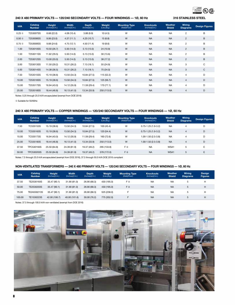
240 X 480 PRIMARY VOLTS — 120/240 SECONDARY VOLTS — FOUR WINDINGS — 1Ø, 60 Hz 316 STAINLESS STEEL
kVACatalog Number
Height (Inches)(Cm.)
Width (Inches)(Cm.)
Depth (Inches)(Cm.)
Weight (Lbs.)(Kg.)
Mounting Type(Wall)(Floor)
Knockouts (Inches)(Cm.)
Weather Shield
Wiring Diagrams
Design Figures
0.25 ① T253007SS 8.68 (22.0) 4.08 (10.4) 3.88 (9.9) 10 (4.5) W NA NA 2 B
0.50 ① T253008SS 9.06 (23.0) 4.37 (11.1) 4.20 (10.7) 15 (6.8) W NA NA 2 B
0.75 ① T253009SS 9.68 (24.6) 4.75 (12.1) 4.50 (11.4) 19 (8.6) W NA NA 2 B
1.00 T253010SS 10.50 (26.7) 5.50 (14.0) 5.13 (13.0) 24 (10.9) W NA NA 2 B
1.50 T253011SS 11.62 (29.5) 5.50 (14.0) 5.13 (13.0) 30 (13.6) W NA NA 2 B
2.00 T253012SS 13.00 (33.0) 5.50 (14.0) 5.13 (13.0) 38 (17.2) W NA NA 2 B
3.00 T253013SS 11.50 (29.2) 10.31 (26.2) 7.13 (18.1) 55 (24.9) W NA NA 3 C
5.00 T253014SS 14.38 (36.5) 10.31 (26.2) 7.13 (18.1) 75 (34.0) W NA NA 3 C
7.50 T253515SS 15.19 (38.6) 13.50 (34.3) 10.84 (27.5) 115 (52.2) W NA NA 4 D
10.00 T253516SS 15.19 (38.6) 13.50 (34.3) 10.84 (27.5) 125 (56.7) W NA NA 4 D
15.00 T253517SS 16.94 (43.0) 14.12 (35.9) 11.59 (29.4) 170 (77.1) W NA NA 4 D
25.00 T253518SS 18.44 (46.8) 16.13 (41.0) 13.34 (33.9) 250 (113.0) W NA NA 4 D
Notes: 0.25 through 25.0 kVA encapsulated (exempt from DOE 2016)
①Suitable for 50/60Hz
240 X 480 PRIMARY VOLTS — COPPER WINDINGS — 120/240 SECONDARY VOLTS — FOUR WINDINGS — 1Ø, 60 Hz
kVACatalog Number
Height (Inches)(Cm.)
Width (Inches)(Cm.)
Depth (Inches)(Cm.)
Weight (Lbs.)(Kg.)
Mounting Type(Wall)(Floor)
Knockouts (Inches)(Cm.)
Weather Shield
Wiring Diagrams
Design Figures
7.50 TC535153S 15.19 (38.6) 13.50 (34.3) 10.84 (27.5) 100 (45.4) W 0.75-1.25 (1.9-3.2) NA 4 D
10.00 TC535163S 15.19 (38.6) 13.50 (34.3) 10.84 (27.5) 120 (54.4) W 0.75-1.25 (1.9-3.2) NA 4 D
15.00 TC535173S 16.94 (43.0) 14.12 (35.9) 11.59 (29.4) 160 (72.6) W 1.00-1.50 (2.5-3.8) NA 4 D
25.00 TC535183S 18.44 (46.8) 16.13 (41.0) 13.34 (33.9) 250 (113.0) W 1.00-1.50 (2.5-3.8) NA 4 D
37.50 TPC530193S 25.50 (64.8) 24.39 (61.9) 19.37 (49.2) 295 (133.8) F ② NA WSA1 5 E
50.00 TPC530203S 25.50 (64.8) 24.39 (61.9) 19.37 (49.2) 378 (172.0) F ② NA WSA1 5 E
Notes: 7.5 through 25.0 kVA encapsulated (exempt from DOE 2016), 37.5 through 50.0 kVA DOE 2016 compliant
NON-VENTILATED TRANSFORMERS — 240 X 480 PRIMARY VOLTS — 120/240 SECONDARY VOLTS — FOUR WINDINGS — 1Ø, 60 Hz
kVACatalog Number
Height (Inches)(Cm.)
Width (Inches)(Cm.)
Depth (Inches)(Cm.)
Weight (Lbs.)(Kg.)
Mounting Type(Wall)(Floor)
Knockouts (Inches)(Cm.)
Weather Shield
Wiring Diagrams
Design Figures
37.50 TE2530193S 35.47 (90.1) 31.90 (81.0) 26.90 (68.3) 430 (195.0) F ② NA NA 5 H
50.00 TE2530203S 35.47 (90.1) 31.90 (81.0) 26.90 (68.3) 430 (195.0) F ② NA NA 5 H
75.00 TE2A530213S 35.47 (90.1) 31.90 (81.0) 26.90 (68.3) 525 (238.0) F NA NA 5 H
100.00 TE1530223S 42.00 (106.7) 40.00 (101.6) 30.00 (76.2) 775 (352.0) F NA NA 5 H
Notes: 37.5 through 100.0 kVA non-ventilated (exempt from DOE 2016)
9
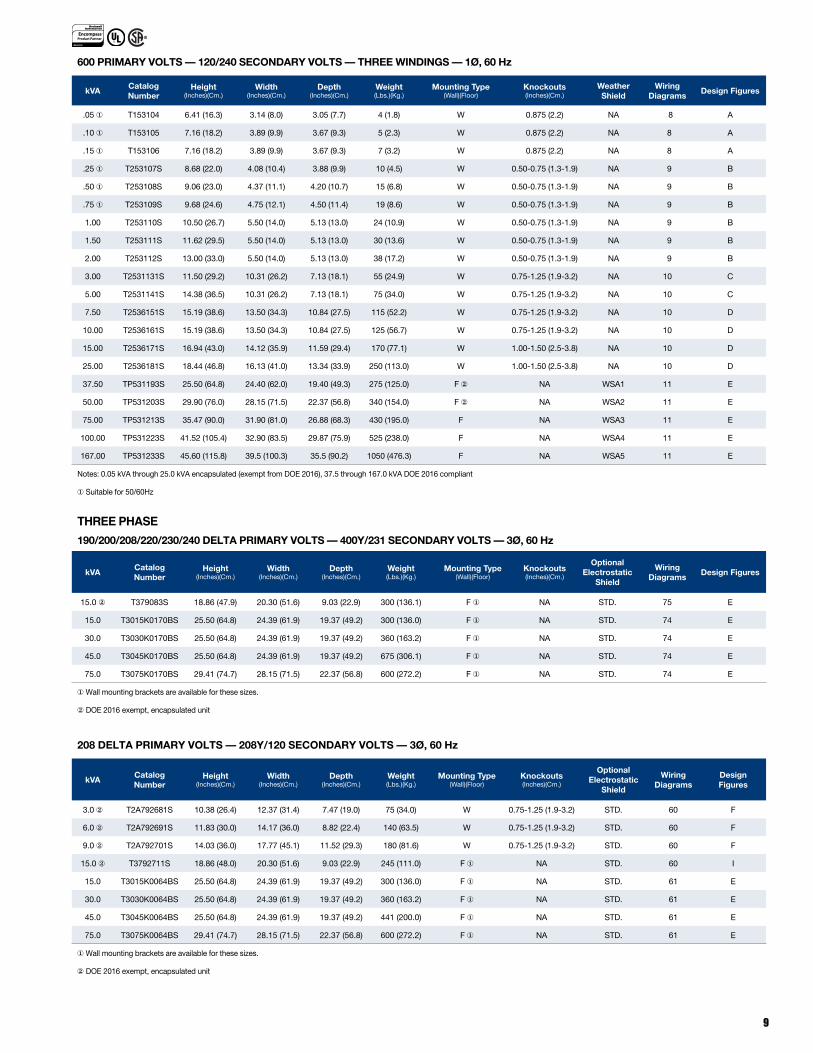
600 PRIMARY VOLTS — 120/240 SECONDARY VOLTS — THREE WINDINGS — 1Ø, 60 Hz
kVACatalog Number
Height (Inches)(Cm.)
Width (Inches)(Cm.)
Depth (Inches)(Cm.)
Weight (Lbs.)(Kg.)
Mounting Type(Wall)(Floor)
Knockouts (Inches)(Cm.)
Weather Shield
Wiring Diagrams
Design Figures
.05 ① T153104 6.41 (16.3) 3.14 (8.0) 3.05 (7.7) 4 (1.8) W 0.875 (2.2) NA 8 A
.10 ① T153105 7.16 (18.2) 3.89 (9.9) 3.67 (9.3) 5 (2.3) W 0.875 (2.2) NA 8 A
.15 ① T153106 7.16 (18.2) 3.89 (9.9) 3.67 (9.3) 7 (3.2) W 0.875 (2.2) NA 8 A
.25 ① T253107S 8.68 (22.0) 4.08 (10.4) 3.88 (9.9) 10 (4.5) W 0.50-0.75 (1.3-1.9) NA 9 B
.50 ① T253108S 9.06 (23.0) 4.37 (11.1) 4.20 (10.7) 15 (6.8) W 0.50-0.75 (1.3-1.9) NA 9 B
.75 ① T253109S 9.68 (24.6) 4.75 (12.1) 4.50 (11.4) 19 (8.6) W 0.50-0.75 (1.3-1.9) NA 9 B
1.00 T253110S 10.50 (26.7) 5.50 (14.0) 5.13 (13.0) 24 (10.9) W 0.50-0.75 (1.3-1.9) NA 9 B
1.50 T253111S 11.62 (29.5) 5.50 (14.0) 5.13 (13.0) 30 (13.6) W 0.50-0.75 (1.3-1.9) NA 9 B
2.00 T253112S 13.00 (33.0) 5.50 (14.0) 5.13 (13.0) 38 (17.2) W 0.50-0.75 (1.3-1.9) NA 9 B
3.00 T2531131S 11.50 (29.2) 10.31 (26.2) 7.13 (18.1) 55 (24.9) W 0.75-1.25 (1.9-3.2) NA 10 C
5.00 T2531141S 14.38 (36.5) 10.31 (26.2) 7.13 (18.1) 75 (34.0) W 0.75-1.25 (1.9-3.2) NA 10 C
7.50 T2536151S 15.19 (38.6) 13.50 (34.3) 10.84 (27.5) 115 (52.2) W 0.75-1.25 (1.9-3.2) NA 10 D
10.00 T2536161S 15.19 (38.6) 13.50 (34.3) 10.84 (27.5) 125 (56.7) W 0.75-1.25 (1.9-3.2) NA 10 D
15.00 T2536171S 16.94 (43.0) 14.12 (35.9) 11.59 (29.4) 170 (77.1) W 1.00-1.50 (2.5-3.8) NA 10 D
25.00 T2536181S 18.44 (46.8) 16.13 (41.0) 13.34 (33.9) 250 (113.0) W 1.00-1.50 (2.5-3.8) NA 10 D
37.50 TP531193S 25.50 (64.8) 24.40 (62.0) 19.40 (49.3) 275 (125.0) F ② NA WSA1 11 E
50.00 TP531203S 29.90 (76.0) 28.15 (71.5) 22.37 (56.8) 340 (154.0) F ② NA WSA2 11 E
75.00 TP531213S 35.47 (90.0) 31.90 (81.0) 26.88 (68.3) 430 (195.0) F NA WSA3 11 E
100.00 TP531223S 41.52 (105.4) 32.90 (83.5) 29.87 (75.9) 525 (238.0) F NA WSA4 11 E
167.00 TP531233S 45.60 (115.8) 39.5 (100.3) 35.5 (90.2) 1050 (476.3) F NA WSA5 11 E
Notes: 0.05 kVA through 25.0 kVA encapsulated (exempt from DOE 2016), 37.5 through 167.0 kVA DOE 2016 compliant
① Suitable for 50/60Hz
THREE PHASE
190/200/208/220/230/240 DELTA PRIMARY VOLTS — 400Y/231 SECONDARY VOLTS — 3Ø, 60 Hz
kVACatalog Number
Height (Inches)(Cm.)
Width (Inches)(Cm.)
Depth (Inches)(Cm.)
Weight (Lbs.)(Kg.)
Mounting Type(Wall)(Floor)
Knockouts (Inches)(Cm.)
Optional Electrostatic
Shield
Wiring Diagrams
Design Figures
15.0 ② T379083S 18.86 (47.9) 20.30 (51.6) 9.03 (22.9) 300 (136.1) F ① NA STD. 75 E
15.0 T3015K0170BS 25.50 (64.8) 24.39 (61.9) 19.37 (49.2) 300 (136.0) F ① NA STD. 74 E
30.0 T3030K0170BS 25.50 (64.8) 24.39 (61.9) 19.37 (49.2) 360 (163.2) F ① NA STD. 74 E
45.0 T3045K0170BS 25.50 (64.8) 24.39 (61.9) 19.37 (49.2) 675 (306.1) F ① NA STD. 74 E
75.0 T3075K0170BS 29.41 (74.7) 28.15 (71.5) 22.37 (56.8) 600 (272.2) F ① NA STD. 74 E
①Wall mounting brackets are available for these sizes.
②DOE 2016 exempt, encapsulated unit
208 DELTA PRIMARY VOLTS — 208Y/120 SECONDARY VOLTS — 3Ø, 60 Hz
kVACatalog Number
Height (Inches)(Cm.)
Width (Inches)(Cm.)
Depth (Inches)(Cm.)
Weight (Lbs.)(Kg.)
Mounting Type(Wall)(Floor)
Knockouts (Inches)(Cm.)
Optional Electrostatic
Shield
Wiring Diagrams
Design Figures
3.0 ② T2A792681S 10.38 (26.4) 12.37 (31.4) 7.47 (19.0) 75 (34.0) W 0.75-1.25 (1.9-3.2) STD. 60 F
6.0 ② T2A792691S 11.83 (30.0) 14.17 (36.0) 8.82 (22.4) 140 (63.5) W 0.75-1.25 (1.9-3.2) STD. 60 F
9.0 ② T2A792701S 14.03 (36.0) 17.77 (45.1) 11.52 (29.3) 180 (81.6) W 0.75-1.25 (1.9-3.2) STD. 60 F
15.0 ② T3792711S 18.86 (48.0) 20.30 (51.6) 9.03 (22.9) 245 (111.0) F ① NA STD. 60 I
15.0 T3015K0064BS 25.50 (64.8) 24.39 (61.9) 19.37 (49.2) 300 (136.0) F ① NA STD. 61 E
30.0 T3030K0064BS 25.50 (64.8) 24.39 (61.9) 19.37 (49.2) 360 (163.2) F ① NA STD. 61 E
45.0 T3045K0064BS 25.50 (64.8) 24.39 (61.9) 19.37 (49.2) 441 (200.0) F ① NA STD. 61 E
75.0 T3075K0064BS 29.41 (74.7) 28.15 (71.5) 22.37 (56.8) 600 (272.2) F ① NA STD. 61 E
①Wall mounting brackets are available for these sizes.
②DOE 2016 exempt, encapsulated unit
10
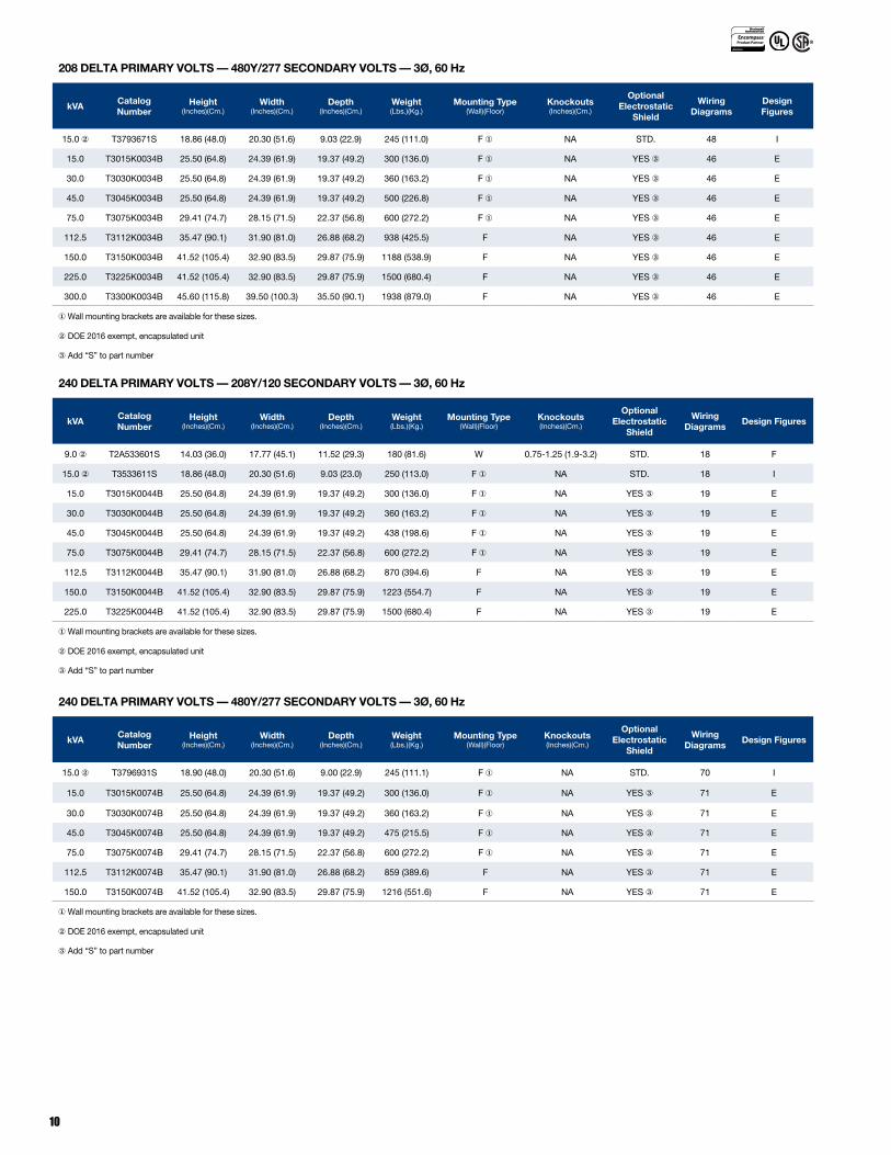
208 DELTA PRIMARY VOLTS — 480Y/277 SECONDARY VOLTS — 3Ø, 60 Hz
kVACatalog Number
Height (Inches)(Cm.)
Width (Inches)(Cm.)
Depth (Inches)(Cm.)
Weight (Lbs.)(Kg.)
Mounting Type(Wall)(Floor)
Knockouts (Inches)(Cm.)
Optional Electrostatic
Shield
Wiring Diagrams
Design Figures
15.0 ② T3793671S 18.86 (48.0) 20.30 (51.6) 9.03 (22.9) 245 (111.0) F ① NA STD. 48 I
15.0 T3015K0034B 25.50 (64.8) 24.39 (61.9) 19.37 (49.2) 300 (136.0) F ① NA YES ③ 46 E
30.0 T3030K0034B 25.50 (64.8) 24.39 (61.9) 19.37 (49.2) 360 (163.2) F ① NA YES ③ 46 E
45.0 T3045K0034B 25.50 (64.8) 24.39 (61.9) 19.37 (49.2) 500 (226.8) F ① NA YES ③ 46 E
75.0 T3075K0034B 29.41 (74.7) 28.15 (71.5) 22.37 (56.8) 600 (272.2) F ① NA YES ③ 46 E
112.5 T3112K0034B 35.47 (90.1) 31.90 (81.0) 26.88 (68.2) 938 (425.5) F NA YES ③ 46 E
150.0 T3150K0034B 41.52 (105.4) 32.90 (83.5) 29.87 (75.9) 1188 (538.9) F NA YES ③ 46 E
225.0 T3225K0034B 41.52 (105.4) 32.90 (83.5) 29.87 (75.9) 1500 (680.4) F NA YES ③ 46 E
300.0 T3300K0034B 45.60 (115.8) 39.50 (100.3) 35.50 (90.1) 1938 (879.0) F NA YES ③ 46 E
①Wall mounting brackets are available for these sizes.
②DOE 2016 exempt, encapsulated unit
③Add “S” to part number
240 DELTA PRIMARY VOLTS — 208Y/120 SECONDARY VOLTS — 3Ø, 60 Hz
kVACatalog Number
Height (Inches)(Cm.)
Width (Inches)(Cm.)
Depth (Inches)(Cm.)
Weight (Lbs.)(Kg.)
Mounting Type(Wall)(Floor)
Knockouts (Inches)(Cm.)
Optional Electrostatic
Shield
Wiring Diagrams
Design Figures
9.0 ② T2A533601S 14.03 (36.0) 17.77 (45.1) 11.52 (29.3) 180 (81.6) W 0.75-1.25 (1.9-3.2) STD. 18 F
15.0 ② T3533611S 18.86 (48.0) 20.30 (51.6) 9.03 (23.0) 250 (113.0) F ① NA STD. 18 I
15.0 T3015K0044B 25.50 (64.8) 24.39 (61.9) 19.37 (49.2) 300 (136.0) F ① NA YES ③ 19 E
30.0 T3030K0044B 25.50 (64.8) 24.39 (61.9) 19.37 (49.2) 360 (163.2) F ① NA YES ③ 19 E
45.0 T3045K0044B 25.50 (64.8) 24.39 (61.9) 19.37 (49.2) 438 (198.6) F ① NA YES ③ 19 E
75.0 T3075K0044B 29.41 (74.7) 28.15 (71.5) 22.37 (56.8) 600 (272.2) F ① NA YES ③ 19 E
112.5 T3112K0044B 35.47 (90.1) 31.90 (81.0) 26.88 (68.2) 870 (394.6) F NA YES ③ 19 E
150.0 T3150K0044B 41.52 (105.4) 32.90 (83.5) 29.87 (75.9) 1223 (554.7) F NA YES ③ 19 E
225.0 T3225K0044B 41.52 (105.4) 32.90 (83.5) 29.87 (75.9) 1500 (680.4) F NA YES ③ 19 E
①Wall mounting brackets are available for these sizes.
②DOE 2016 exempt, encapsulated unit
③Add “S” to part number
240 DELTA PRIMARY VOLTS — 480Y/277 SECONDARY VOLTS — 3Ø, 60 Hz
kVACatalog Number
Height (Inches)(Cm.)
Width (Inches)(Cm.)
Depth (Inches)(Cm.)
Weight (Lbs.)(Kg.)
Mounting Type(Wall)(Floor)
Knockouts (Inches)(Cm.)
Optional Electrostatic
Shield
Wiring Diagrams
Design Figures
15.0 ② T3796931S 18.90 (48.0) 20.30 (51.6) 9.00 (22.9) 245 (111.1) F ① NA STD. 70 I
15.0 T3015K0074B 25.50 (64.8) 24.39 (61.9) 19.37 (49.2) 300 (136.0) F ① NA YES ③ 71 E
30.0 T3030K0074B 25.50 (64.8) 24.39 (61.9) 19.37 (49.2) 360 (163.2) F ① NA YES ③ 71 E
45.0 T3045K0074B 25.50 (64.8) 24.39 (61.9) 19.37 (49.2) 475 (215.5) F ① NA YES ③ 71 E
75.0 T3075K0074B 29.41 (74.7) 28.15 (71.5) 22.37 (56.8) 600 (272.2) F ① NA YES ③ 71 E
112.5 T3112K0074B 35.47 (90.1) 31.90 (81.0) 26.88 (68.2) 859 (389.6) F NA YES ③ 71 E
150.0 T3150K0074B 41.52 (105.4) 32.90 (83.5) 29.87 (75.9) 1216 (551.6) F NA YES ③ 71 E
①Wall mounting brackets are available for these sizes.
②DOE 2016 exempt, encapsulated unit
③Add “S” to part number
11
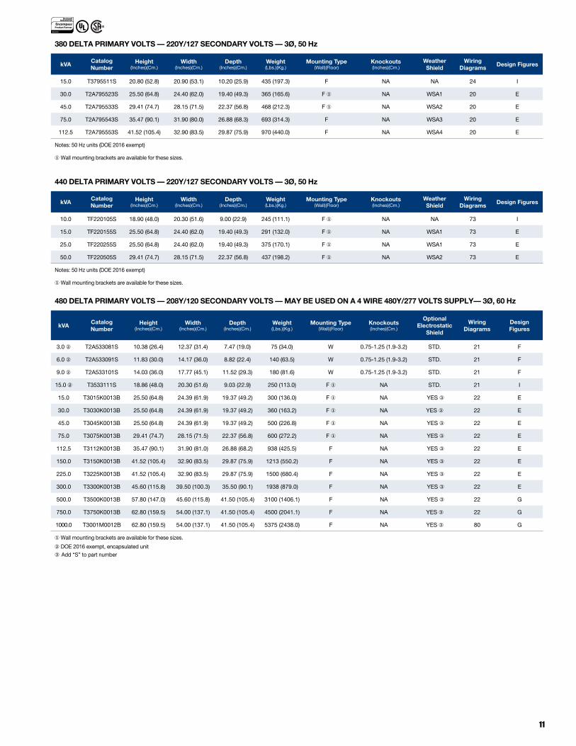
380 DELTA PRIMARY VOLTS — 220Y/127 SECONDARY VOLTS — 3Ø, 50 Hz
kVACatalog Number
Height (Inches)(Cm.)
Width (Inches)(Cm.)
Depth (Inches)(Cm.)
Weight (Lbs.)(Kg.)
Mounting Type(Wall)(Floor)
Knockouts (Inches)(Cm.)
Weather Shield
Wiring Diagrams
Design Figures
15.0 T3795511S 20.80 (52.8) 20.90 (53.1) 10.20 (25.9) 435 (197.3) F NA NA 24 I
30.0 T2A795523S 25.50 (64.8) 24.40 (62.0) 19.40 (49.3) 365 (165.6) F ① NA WSA1 20 E
45.0 T2A795533S 29.41 (74.7) 28.15 (71.5) 22.37 (56.8) 468 (212.3) F ① NA WSA2 20 E
75.0 T2A795543S 35.47 (90.1) 31.90 (80.0) 26.88 (68.3) 693 (314.3) F NA WSA3 20 E
112.5 T2A795553S 41.52 (105.4) 32.90 (83.5) 29.87 (75.9) 970 (440.0) F NA WSA4 20 E
Notes: 50 Hz units (DOE 2016 exempt)
①Wall mounting brackets are available for these sizes.
440 DELTA PRIMARY VOLTS — 220Y/127 SECONDARY VOLTS — 3Ø, 50 Hz
kVACatalog Number
Height (Inches)(Cm.)
Width (Inches)(Cm.)
Depth (Inches)(Cm.)
Weight (Lbs.)(Kg.)
Mounting Type(Wall)(Floor)
Knockouts (Inches)(Cm.)
Weather Shield
Wiring Diagrams
Design Figures
10.0 TF220105S 18.90 (48.0) 20.30 (51.6) 9.00 (22.9) 245 (111.1) F ① NA NA 73 I
15.0 TF220155S 25.50 (64.8) 24.40 (62.0) 19.40 (49.3) 291 (132.0) F ① NA WSA1 73 E
25.0 TF220255S 25.50 (64.8) 24.40 (62.0) 19.40 (49.3) 375 (170.1) F ① NA WSA1 73 E
50.0 TF220505S 29.41 (74.7) 28.15 (71.5) 22.37 (56.8) 437 (198.2) F ① NA WSA2 73 E
Notes: 50 Hz units (DOE 2016 exempt)
①Wall mounting brackets are available for these sizes.
480 DELTA PRIMARY VOLTS — 208Y/120 SECONDARY VOLTS — MAY BE USED ON A 4 WIRE 480Y/277 VOLTS SUPPLY— 3Ø, 60 Hz
kVACatalog Number
Height (Inches)(Cm.)
Width (Inches)(Cm.)
Depth (Inches)(Cm.)
Weight (Lbs.)(Kg.)
Mounting Type(Wall)(Floor)
Knockouts (Inches)(Cm.)
Optional Electrostatic
Shield
Wiring Diagrams
Design Figures
3.0 ② T2A533081S 10.38 (26.4) 12.37 (31.4) 7.47 (19.0) 75 (34.0) W 0.75-1.25 (1.9-3.2) STD. 21 F
6.0 ② T2A533091S 11.83 (30.0) 14.17 (36.0) 8.82 (22.4) 140 (63.5) W 0.75-1.25 (1.9-3.2) STD. 21 F
9.0 ② T2A533101S 14.03 (36.0) 17.77 (45.1) 11.52 (29.3) 180 (81.6) W 0.75-1.25 (1.9-3.2) STD. 21 F
15.0 ② T3533111S 18.86 (48.0) 20.30 (51.6) 9.03 (22.9) 250 (113.0) F ① NA STD. 21 I
15.0 T3015K0013B 25.50 (64.8) 24.39 (61.9) 19.37 (49.2) 300 (136.0) F ① NA YES ③ 22 E
30.0 T3030K0013B 25.50 (64.8) 24.39 (61.9) 19.37 (49.2) 360 (163.2) F ① NA YES ③ 22 E
45.0 T3045K0013B 25.50 (64.8) 24.39 (61.9) 19.37 (49.2) 500 (226.8) F ① NA YES ③ 22 E
75.0 T3075K0013B 29.41 (74.7) 28.15 (71.5) 22.37 (56.8) 600 (272.2) F ① NA YES ③ 22 E
112.5 T3112K0013B 35.47 (90.1) 31.90 (81.0) 26.88 (68.2) 938 (425.5) F NA YES ③ 22 E
150.0 T3150K0013B 41.52 (105.4) 32.90 (83.5) 29.87 (75.9) 1213 (550.2) F NA YES ③ 22 E
225.0 T3225K0013B 41.52 (105.4) 32.90 (83.5) 29.87 (75.9) 1500 (680.4) F NA YES ③ 22 E
300.0 T3300K0013B 45.60 (115.8) 39.50 (100.3) 35.50 (90.1) 1938 (879.0) F NA YES ③ 22 E
500.0 T3500K0013B 57.80 (147.0) 45.60 (115.8) 41.50 (105.4) 3100 (1406.1) F NA YES ③ 22 G
750.0 T3750K0013B 62.80 (159.5) 54.00 (137.1) 41.50 (105.4) 4500 (2041.1) F NA YES ③ 22 G
1000.0 T3001M0012B 62.80 (159.5) 54.00 (137.1) 41.50 (105.4) 5375 (2438.0) F NA YES ③ 80 G
① Wall mounting brackets are available for these sizes.
②DOE 2016 exempt, encapsulated unit③Add “S” to part number

12
480 DELTA PRIMARY VOLTS –– COPPER WINDINGS –– 208Y/120 SECONDARY VOLTS –– 3Ø, 60 Hz
kVACatalog Number
Height (Inches)(Cm.)
Width (Inches)(Cm.)
Depth (Inches)(Cm.)
Weight (Lbs.)(Kg.)
Mounting Type(Wall)(Floor)
Knockouts (Inches)(Cm.)
Optional Electrostatic
Shield
Wiring Diagrams
Design Figures
15.0 ② TC533111S 18.86 (48.0) 20.30 (51.6) 9.03 (22.9) 245 (111.0) F ① NA STD. 21 I
15.0 T3015K0013BC 25.50 (64.8) 24.39 (61.9) 19.37 (49.2) 353 (160.1) F ① NA YES ③ 22 E
30.0 T3030K0013BC 25.50 (64.8) 24.39 (61.9) 19.37 (49.2) 498 (225.9) F ① NA YES ③ 22 E
45.0 T3045K0013BC 25.50 (64.8) 24.39 (61.9) 19.37 (49.2) 572 (259.5) F ① NA YES ③ 22 E
75.0 T3075K0013BC 29.41 (74.7) 28.15 (71.5) 22.37 (56.8) 750 (340.2) F NA YES ③ 22 E
112.5 T3112K0013BC 35.47 (90.1) 31.90 (81.0) 26.88 (68.2) 1103 (500.3) F NA YES ③ 22 E
150.0 T3150K0013BC 41.52 (105.4) 32.90 (83.5) 29.87 (75.9) 1477 (669.9) F NA YES ③ 22 E
225.0 T3225K0013BC 41.52 (105.4) 32.90 (83.5) 29.87 (75.9) 1872 (849.1) F NA YES ③ 22 E
300.0 T3300K0013BC 45.60 (115.8) 39.50 (100.3) 35.50 (90.1) 2233 (1012.9) F NA YES ③ 22 E
500.0 T3500K0013BC 57.80 (147.0) 45.60 (115.8) 41.50 (105.4) 4059 (1841.1) F NA YES ③ 22 G
750.0 T3750K0013BC 62.80 (159.5) 54.00 (137.1) 41.50 (105.4) 6192 (2808.6) F NA YES ③ 22 G
① Wall mounting brackets are available for these sizes.
②DOE 2016 exempt, encapsulated unit, 115º C rise
③Add “S” to part number
80° C RISE480 DELTA PRIMARY VOLTS — 208Y/120 SECONDARY VOLTS — MAY BE USED ON A 4 WIRE 480Y/277 VOLTS SUPPLY— 3Ø, 60 Hz
kVA Catalog Number Height (Inches)(Cm.)
Width (Inches)(Cm.)
Depth (Inches)(Cm.)
Weight (Lbs.)(Kg.)
Mounting Type(Wall)(Floor)
Knockouts (Inches)(Cm.)
OptionalElectrostatic
Shield
Wiring Diagrams
Design Figures
15.0 T3015K0013BSB 25.50 (64.8) 24.39 (61.9) 19.37 (49.2) 378 (171.5) F ① NA STD. 22 E
30.0 T3030K0013BSB 25.50 (64.8) 24.39 (61.9) 19.37 (49.2) 550 (249.5) F ① NA STD. 22 E
45.0 T3045K0013BSB 29.41 (74.7) 28.15 (71.5) 22.37 (56.8) 755 (342.5) F NA STD. 22 E
75.0 T3075K0013BSB 35.47 (90.1) 31.90 (81.0) 26.88 (68.2) 1054 (478.1) F NA STD. 22 E
112.5 T3112K0013BSB 41.52 (105.4) 32.90 (83.5) 29.87 (75.9) 1454 (659.5) F NA STD. 22 E
150.0 T3150K0013BSB 41.52 (105.4) 32.90 (83.5) 29.87 (75.9) 1729 (784.3) F NA STD. 22 E
For Copper wound transformers consult factory.
① Wall mounting brackets are available for these sizes.
115° C RISE480 DELTA PRIMARY VOLTS — 208Y/120 SECONDARY VOLTS — 3Ø, 60 Hz ENCAPSULATED TRANSFORMERS
kVACatalog Number
Height (Inches)(Cm.)
Width (Inches)(Cm.)
Depth (Inches)(Cm.)
Weight (Lbs.)(Kg.)
Mounting Type(Wall)(Floor)
Knockouts (Inches)(Cm.)
OptionalElectrostatic
Shield
Wiring Diagrams
Design Figures
30.0 T3793123S 24.81 (63.0) 27.13 (68.9) 11.14 (28.3) 613 (278.1) F NA STD. 22 I
45.0 T3793133S 25.31 (64.3) 30.18 (76.7) 12.76 (32.4) 780 (354.0) F NA STD. 22 I
75.0 T3793143S 26.82 (68.1) 34.68 (88.1) 15.25 (38.7) 1126 (511.0) F NA STD. 22 I
Notes: 30.0 through 75.0 kVA encapsulated (DOE 2016 exempt)
115° C RISE480 DELTA PRIMARY VOLTS — 208Y/120 SECONDARY VOLTS — MAY BE USED ON A 4 WIRE 480Y/277 VOLTS SUPPLY— 3Ø, 60 Hz
kVA Catalog Number Height (Inches)(Cm.)
Width (Inches)(Cm.)
Depth (Inches)(Cm.)
Weight (Lbs.)(Kg.)
Mounting Type(Wall)(Floor)
Knockouts (Inches)(Cm.)
OptionalElectrostatic
Shield
Wiring Diagrams
Design Figures
15.0 T3015K0013BSF 25.50 (64.8) 24.39 (61.9) 19.37 (49.2) 300 (136.0) F ① NA STD. 22 E
30.0 T3030K0013BSF 25.50 (64.8) 24.39 (61.9) 19.37 (49.2) 360 (163.3) F ① NA STD. 22 E
45.0 T3045K0013BSF 25.50 (64.8) 24.39 (61.9) 19.37 (49.2) 500 (226.8) F ① NA STD. 22 E
75.0 T3075K0013BSF 29.41 (74.7) 28.15 (71.5) 22.37 (56.8) 600 (272.2) F ① NA STD. 22 E
112.5 T3112K0013BSF 35.47 (90.1) 31.90 (81.0) 26.88 (68.2) 938 (425.5) F NA STD. 22 E
150.0 T3150K0013BSF 41.52 (105.4) 32.90 (83.5) 29.87 (75.9) 1213 (550.2) F NA STD. 22 E
225.0 T3225K0013BSF 45.60 (115.8) 39.50 (100.3) 35.50 (90.1) 2298 (1042.3) F NA STD. 22 E
300.0 T3300K0013BSF 45.60 (115.8) 39.50 (100.3) 35.50 (90.1) 2319 (1051.9) F NA STD. 22 E
500.0 T3500K0013BSF 57.80 (147.0) 45.60 (115.8) 41.50 (105.4) 4156 (1885.1) F NA STD. 22 G
①Wall mounting brackets are available for these sizes.
13
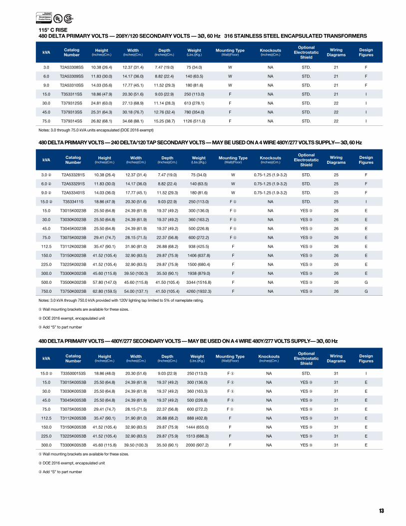
115° C RISE480 DELTA PRIMARY VOLTS — 208Y/120 SECONDARY VOLTS — 3Ø, 60 Hz 316 STAINLESS STEEL ENCAPSULATED TRANSFORMERS
kVACatalog Number
Height (Inches)(Cm.)
Width (Inches)(Cm.)
Depth (Inches)(Cm.)
Weight (Lbs.)(Kg.)
Mounting Type(Wall)(Floor)
Knockouts (Inches)(Cm.)
OptionalElectrostatic
Shield
Wiring Diagrams
Design Figures
3.0 T2A53308SS 10.38 (26.4) 12.37 (31.4) 7.47 (19.0) 75 (34.0) W NA STD. 21 F
6.0 T2A53309SS 11.83 (30.0) 14.17 (36.0) 8.82 (22.4) 140 (63.5) W NA STD. 21 F
9.0 T2A53310SS 14.03 (35.6) 17.77 (45.1) 11.52 (29.3) 180 (81.6) W NA STD. 21 F
15.0 T353311SS 18.86 (47.9) 20.30 (51.6) 9.03 (22.9) 250 (113.0) F NA STD. 21 I
30.0 T379312SS 24.81 (63.0) 27.13 (68.9) 11.14 (28.3) 613 (278.1) F NA STD. 22 I
45.0 T379313SS 25.31 (64.3) 30.18 (76.7) 12.76 (32.4) 780 (354.0) F NA STD. 22 I
75.0 T379314SS 26.82 (68.1) 34.68 (88.1) 15.25 (38.7) 1126 (511.0) F NA STD. 22 I
Notes: 3.0 through 75.0 kVA units encapsulated (DOE 2016 exempt)
480 DELTA PRIMARY VOLTS — 240 DELTA/120 TAP SECONDARY VOLTS — MAY BE USED ON A 4 WIRE 480Y/277 VOLTS SUPPLY— 3Ø, 60 Hz
kVACatalog Number
Height (Inches)(Cm.)
Width (Inches)(Cm.)
Depth (Inches)(Cm.)
Weight (Lbs.)(Kg.)
Mounting Type(Wall)(Floor)
Knockouts (Inches)(Cm.)
Optional Electrostatic
Shield
Wiring Diagrams
Design Figures
3.0 ② T2A533281S 10.38 (26.4) 12.37 (31.4) 7.47 (19.0) 75 (34.0) W 0.75-1.25 (1.9-3.2) STD. 25 F
6.0 ② T2A533291S 11.83 (30.0) 14.17 (36.0) 8.82 (22.4) 140 (63.5) W 0.75-1.25 (1.9-3.2) STD. 25 F
9.0 ② T2A533401S 14.03 (36.0) 17.77 (45.1) 11.52 (29.3) 180 (81.6) W 0.75-1.25 (1.9-3.2) STD. 25 F
15.0 ② T3533411S 18.86 (47.9) 20.30 (51.6) 9.03 (22.9) 250 (113.0) F ① NA STD. 25 I
15.0 T3015K0023B 25.50 (64.8) 24.39 (61.9) 19.37 (49.2) 300 (136.0) F ① NA YES ③ 26 E
30.0 T3030K0023B 25.50 (64.8) 24.39 (61.9) 19.37 (49.2) 360 (163.2) F ① NA YES ③ 26 E
45.0 T3045K0023B 25.50 (64.8) 24.39 (61.9) 19.37 (49.2) 500 (226.8) F ① NA YES ③ 26 E
75.0 T3075K0023B 29.41 (74.7) 28.15 (71.5) 22.37 (56.8) 600 (272.2) F ① NA YES ③ 26 E
112.5 T3112K0023B 35.47 (90.1) 31.90 (81.0) 26.88 (68.2) 938 (425.5) F NA YES ③ 26 E
150.0 T3150K0023B 41.52 (105.4) 32.90 (83.5) 29.87 (75.9) 1406 (637.8) F NA YES ③ 26 E
225.0 T3225K0023B 41.52 (105.4) 32.90 (83.5) 29.87 (75.9) 1500 (680.4) F NA YES ③ 26 E
300.0 T3300K0023B 45.60 (115.8) 39.50 (100.3) 35.50 (90.1) 1938 (879.0) F NA YES ③ 26 E
500.0 T3500K0023B 57.80 (147.0) 45.60 (115.8) 41.50 (105.4) 3344 (1516.8) F NA YES ③ 26 G
750.0 T3750K0023B 62.80 (159.5) 54.00 (137.1) 41.50 (105.4) 4260 (1932.3) F NA YES ③ 26 G
Notes: 3.0 kVA through 750.0 kVA provided with 120V lighting tap limited to 5% of nameplate rating.
① Wall mounting brackets are available for these sizes.
②DOE 2016 exempt, encapsulated unit
③Add “S” to part number
480 DELTA PRIMARY VOLTS — 480Y/277 SECONDARY VOLTS — MAY BE USED ON A 4 WIRE 480Y/277 VOLTS SUPPLY— 3Ø, 60 Hz
kVACatalog Number
Height (Inches)(Cm.)
Width (Inches)(Cm.)
Depth (Inches)(Cm.)
Weight (Lbs.)(Kg.)
Mounting Type(Wall)(Floor)
Knockouts (Inches)(Cm.)
Optional Electrostatic
Shield
Wiring Diagrams
Design Figures
15.0 ② T335000153S 18.86 (48.0) 20.30 (51.6) 9.03 (22.9) 250 (113.0) F ① NA STD. 31 I
15.0 T3015K0053B 25.50 (64.8) 24.39 (61.9) 19.37 (49.2) 300 (136.0) F ① NA YES ③ 31 E
30.0 T3030K0053B 25.50 (64.8) 24.39 (61.9) 19.37 (49.2) 360 (163.3) F ① NA YES ③ 31 E
45.0 T3045K0053B 25.50 (64.8) 24.39 (61.9) 19.37 (49.2) 500 (226.8) F ① NA YES ③ 31 E
75.0 T3075K0053B 29.41 (74.7) 28.15 (71.5) 22.37 (56.8) 600 (272.2) F ① NA YES ③ 31 E
112.5 T3112K0053B 35.47 (90.1) 31.90 (81.0) 26.88 (68.2) 888 (402.8) F NA YES ③ 31 E
150.0 T3150K0053B 41.52 (105.4) 32.90 (83.5) 29.87 (75.9) 1444 (655.0) F NA YES ③ 31 E
225.0 T3225K0053B 41.52 (105.4) 32.90 (83.5) 29.87 (75.9) 1513 (686.3) F NA YES ③ 31 E
300.0 T3300K0053B 45.60 (115.8) 39.50 (100.3) 35.50 (90.1) 2000 (907.2) F NA YES ③ 31 E
①Wall mounting brackets are available for these sizes.
②DOE 2016 exempt, encapsulated unit
③Add “S” to part number
14
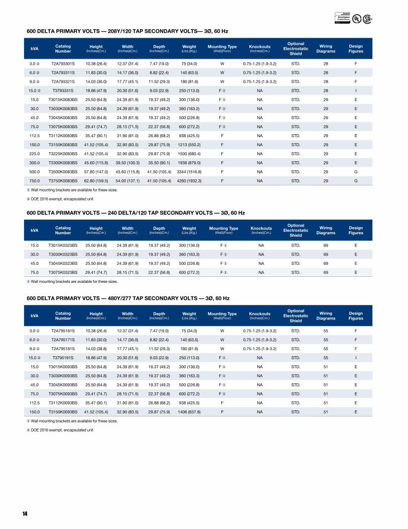
600 DELTA PRIMARY VOLTS — 208Y/120 TAP SECONDARY VOLTS— 3Ø, 60 Hz
kVACatalog Number
Height (Inches)(Cm.)
Width (Inches)(Cm.)
Depth (Inches)(Cm.)
Weight (Lbs.)(Kg.)
Mounting Type(Wall)(Floor)
Knockouts (Inches)(Cm.)
Optional Electrostatic
Shield
Wiring Diagrams
Design Figures
3.0 ② T2A793301S 10.38 (26.4) 12.37 (31.4) 7.47 (19.0) 75 (34.0) W 0.75-1.25 (1.9-3.2) STD. 28 F
6.0 ② T2A793311S 11.83 (30.0) 14.17 (36.0) 8.82 (22.4) 140 (63.5) W 0.75-1.25 (1.9-3.2) STD. 28 F
9.0 ② T2A793321S 14.03 (36.0) 17.77 (45.1) 11.52 (29.3) 180 (81.6) W 0.75-1.25 (1.9-3.2) STD. 28 F
15.0 ② T3793331S 18.86 (47.9) 20.30 (51.6) 9.03 (22.9) 250 (113.0) F ① NA STD. 28 I
15.0 T3015K0083BS 25.50 (64.8) 24.39 (61.9) 19.37 (49.2) 300 (136.0) F ① NA STD. 29 E
30.0 T3030K0083BS 25.50 (64.8) 24.39 (61.9) 19.37 (49.2) 360 (163.2) F ① NA STD. 29 E
45.0 T3045K0083BS 25.50 (64.8) 24.39 (61.9) 19.37 (49.2) 500 (226.8) F ① NA STD. 29 E
75.0 T3075K0083BS 29.41 (74.7) 28.15 (71.5) 22.37 (56.8) 600 (272.2) F ① NA STD. 29 E
112.5 T3112K0083BS 35.47 (90.1) 31.90 (81.0) 26.88 (68.2) 938 (425.5) F NA STD. 29 E
150.0 T3150K0083BS 41.52 (105.4) 32.90 (83.5) 29.87 (75.9) 1213 (550.2) F NA STD. 29 E
225.0 T3225K0083BS 41.52 (105.4) 32.90 (83.5) 29.87 (75.9) 1500 (680.4) F NA STD. 29 E
300.0 T3300K0083BS 45.60 (115.8) 39.50 (100.3) 35.50 (90.1) 1938 (879.0) F NA STD. 29 E
500.0 T3500K0083BS 57.80 (147.0) 45.60 (115.8) 41.50 (105.4) 3344 (1516.8) F NA STD. 29 G
750.0 T3750K0083BS 62.80 (159.5) 54.00 (137.1) 41.50 (105.4) 4260 (1932.3) F NA STD. 29 G
① Wall mounting brackets are available for these sizes.
②DOE 2016 exempt, encapsulated unit
600 DELTA PRIMARY VOLTS — 480Y/277 TAP SECONDARY VOLTS — 3Ø, 60 Hz
kVACatalog Number
Height (Inches)(Cm.)
Width (Inches)(Cm.)
Depth (Inches)(Cm.)
Weight (Lbs.)(Kg.)
Mounting Type(Wall)(Floor)
Knockouts (Inches)(Cm.)
Optional Electrostatic
Shield
Wiring Diagrams
Design Figures
3.0 ② T2A795161S 10.38 (26.4) 12.37 (31.4) 7.47 (19.0) 75 (34.0) W 0.75-1.25 (1.9-3.2) STD. 55 F
6.0 ② T2A795171S 11.83 (30.0) 14.17 (36.0) 8.82 (22.4) 140 (63.5) W 0.75-1.25 (1.9-3.2) STD. 55 F
9.0 ② T2A795181S 14.03 (38.8) 17.77 (45.1) 11.52 (29.3) 180 (81.6) W 0.75-1.25 (1.9-3.2) STD. 55 F
15.0 ② T3795191S 18.86 (47.9) 20.30 (51.6) 9.03 (22.9) 250 (113.0) F ① NA STD. 55 I
15.0 T3015K0093BS 25.50 (64.8) 24.39 (61.9) 19.37 (49.2) 300 (136.0) F ① NA STD. 51 E
30.0 T3030K0093BS 25.50 (64.8) 24.39 (61.9) 19.37 (49.2) 360 (163.3) F ① NA STD. 51 E
45.0 T3045K0093BS 25.50 (64.8) 24.39 (61.9) 19.37 (49.2) 500 (226.8) F ① NA STD. 51 E
75.0 T3075K0093BS 29.41 (74.7) 28.15 (71.5) 22.37 (56.8) 600 (272.2) F ① NA STD. 51 E
112.5 T3112K0093BS 35.47 (90.1) 31.90 (81.0) 26.88 (68.2) 938 (425.5) F NA STD. 51 E
150.0 T3150K0093BS 41.52 (105.4) 32.90 (83.5) 29.87 (75.9) 1406 (637.8) F NA STD. 51 E
① Wall mounting brackets are available for these sizes.
②DOE 2016 exempt, encapsulated unit
600 DELTA PRIMARY VOLTS — 240 DELTA/120 TAP SECONDARY VOLTS — 3Ø, 60 Hz
kVACatalog Number
Height (Inches)(Cm.)
Width (Inches)(Cm.)
Depth (Inches)(Cm.)
Weight (Lbs.)(Kg.)
Mounting Type(Wall)(Floor)
Knockouts (Inches)(Cm.)
Optional Electrostatic
Shield
Wiring Diagrams
Design Figures
15.0 T3015K0323BS 25.50 (64.8) 24.39 (61.9) 19.37 (49.2) 300 (136.0) F ① NA STD. 69 E
30.0 T3030K0323BS 25.50 (64.8) 24.39 (61.9) 19.37 (49.2) 360 (163.3) F ① NA STD. 69 E
45.0 T3045K0323BS 25.50 (64.8) 24.39 (61.9) 19.37 (49.2) 500 (226.8) F ① NA STD. 69 E
75.0 T3075K0323BS 29.41 (74.7) 28.15 (71.5) 22.37 (56.8) 600 (272.2) F ① NA STD. 69 E
① Wall mounting brackets are available for these sizes.

15
600 PRIMARY VOLTS — 480 SECONDARY VOLTS — 3Ø, 60 Hz
480 PRIMARY VOLTS — 380 SECONDARY VOLTS — 3Ø, 50/60 Hz AUTO TRANSFORMERS
kVA ①
Primary 600VSecondary
480V
Primary 480VSecondary
380V
CatalogNumber
Height(Inches)(Cm.)
Width(Inches)(Cm.
Depth(Inches)(Cm.
Weight(Lbs.)(Kg.)
MountingType
(Wall)(Floor)
Knockouts(Inches)(Cm.
Weather Shield
Wiring Diagrams
Design Figures
15.0 12.0 T2527031③ 15.21 (38.6) 19.25 (48.9) 7.37 (18.7) 104 (47.2) W NA NA 56 F
30.0 24.0 T2527051③ 15.21 (38.6) 19.25 (48.9) 7.37 (18.7) 152 (68.9) W NA NA 56 F
45.0 36.0 T2527071③ 15.21 (38.6) 19.25 (48.9) 7.37 (18.7) 156 (70.8) W NA NA 56 F
75.0 60.0 T3527101③ 18.86 (47.9) 20.30 (51.6) 9.03 (22.9) 300 (136.1) F ⑤ NA NA 56 I
112.5 90.0 T2A527121④ 25.50 (64.8) 24.40 (62.0) 19.40 (49.3) 325 (147.0) F ① NA WSA1 57 E
150.0 120.0 T2A527131④ 25.50 (64.8) 24.40 (62.0) 19.40 (49.3) 350 (158.8) F ① NA WSA1 57 E
225.0 180.0 T2A527151④ 29.41 (74.7) 28.15 (71.5) 22.37 (56.8) 600 (272.0) F ① NA WSA2 57 E
300.0 240.0 T2A527171④ 29.41 (74.7) 28.15 (71.5) 22.37 (56.8) 650 (294.8) F NA WSA2 57 E
450.0 360.0 T2A527181④ 35.47 (90.1) 31.90 (81.0) 26.88 (68.3) 750 (340.0) F NA WSA3 57 E
500.0 400.0 T2A527191④ 35.47 (90.1) 31.90 (81.0) 26.88 (68.3) 790 (358.3) F NA WSA3 57 E
Notes: Autotransformer DOE 2106 exempt
① Wall mounting brackets are available for these sizes.
②If used on unbalanced loads, these units should only be used on a 4 wire system with the supply neutral connected to the transformer. If used on balanced loads, such as motor loads,
then they may be used on a 3 wire system without a neutral or 4th wire.
③These units are encapsulated with a 115° C temperature rise.

ACM_BRO_032_1016
800.334.5214
hubbell-acmeelectric.com
Hubbell Canada Inc. 905-839-1138 Hubbell de Mexico, S.A. de C.V. 52-55-9151-9999