Embed Size (px)
Citation preview
E1
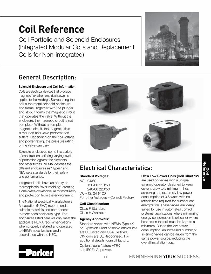
General Description:
Solenoid Enclosure and Coil Information
Coils are electrical devices that produce
magnetic flux when electrical power is
applied to the windings. Surrounding the
coil is the metal solenoid enclosure
and frame. Together with the plunger
and stop, it forms the magnetic circuit
that operates the valve. Without the
enclosure, the magnetic circuit is not
complete. Without a complete
magnetic circuit, the magnetic field
is reduced and valve performance
suffers. Depending on the coil voltage
and power rating, the pressure rating
of the valve can vary.
Solenoid enclosures come in a variety
of constructions offering varying levels
of protection against the elements
and other forces. NEMA identifies the
different enclosures as “Types” and
NEC sets standards for their safety
and performance.
Integrated coils have an epoxy or
thermoplastic "over-molding" creating
a one-piece coil/enclosure for modularity
and protection from the environment.
The National Electrical Manufacturers
Association (NEMA) recommends
suitable materials and components
to meet each enclosure type. The
enclosures listed here will only meet the
applicable NEMA recommendations
when properly installed and operated
to NEMA specifications and in
accordance with the NEC.
Electrical Characteristics:
Standard Voltages:
AC – 24/60
120/60 110/50
240/60 220/50
DC – 12, 24 &120
For other Voltages – Consult Factory
Coil Classification:
Class F Standard
Class H Available
Agency Approvals:
Standard valves with NEMA Type 4X
or Explosion Proof solenoid enclosures
are UL Listed and CSA Certified.
DIN coils are UL Recognized. For
additional details, consult factory.
Optional coils feature ATEX
and IECEx Approvals.
Ultra Low Power Coils (Coil Chart 12)
are used on valves with a unique
solenoid operator designed to keep
current draw to a minimum, thus
achieving the extremely low power
consumption of 0.6 watts with no
refresh time required for subsequent
energization. These valves are ideally
suited for use in automated control
systems, applications where minimizing
energy consumption is critical or where
heat rise in the coil must be kept to a
minimum. Due to the low power
consumption, an increased number of
solenoid valves can be driven from the
same power source, reducing the
overall installation cost.
Coil ReferenceCoil Portfolio and Solenoid Enclosures
(Integrated Modular Coils and Replacement
Coils for Non-integrated)
Coil
Refe
rence
E2Parker Hannifin CorporationFluid Control Division
1 800 825 8305 (1 800 Valve05)www.parker.com/fcd
Coil
Refe
rence
Coil
Chart
s 1-3
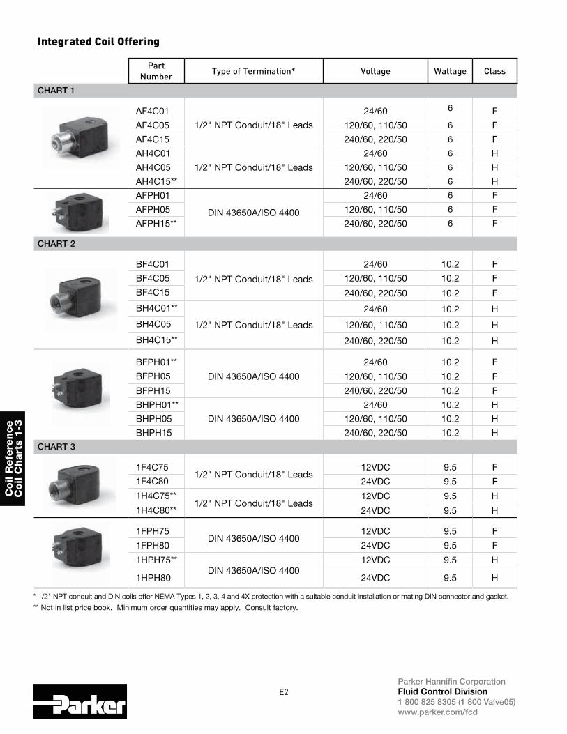
Integrated Coil Offering
Part
NumberType of Termination* Voltage Wattage Class
CHART 1
AF4C01
1/2" NPT Conduit/18" Leads
24/60 6 F
AF4C05 120/60, 110/50 6 F
AF4C15 240/60, 220/50 6 F
AH4C01
1/2" NPT Conduit/18" Leads
24/60 6 H
AH4C05 120/60, 110/50 6 H
AH4C15** 240/60, 220/50 6 H
AFPH01
DIN 43650A/ISO 4400
24/60 6 F
AFPH05 120/60, 110/50 6 F
AFPH15** 240/60, 220/50 6 F
CHART 2
BF4C01
1/2" NPT Conduit/18" Leads
24/60 10.2 F
BF4C05 120/60, 110/50 10.2 F
BF4C15 240/60, 220/50 10.2 F
BH4C01**
1/2" NPT Conduit/18" Leads
24/60 10.2 H
BH4C05 120/60, 110/50 10.2 H
BH4C15** 240/60, 220/50 10.2 H
BFPH01**
DIN 43650A/ISO 4400
24/60 10.2 F
BFPH05 120/60, 110/50 10.2 F
BFPH15 240/60, 220/50 10.2 F
BHPH01**
DIN 43650A/ISO 4400
24/60 10.2 H
BHPH05 120/60, 110/50 10.2 H
BHPH15 240/60, 220/50 10.2 H
CHART 3
1F4C751/2" NPT Conduit/18" Leads
12VDC 9.5 F
1F4C80 24VDC 9.5 F
1H4C75**1/2" NPT Conduit/18" Leads
12VDC 9.5 H
1H4C80** 24VDC 9.5 H
1FPH75DIN 43650A/ISO 4400
12VDC 9.5 F
1FPH80 24VDC 9.5 F
1HPH75**DIN 43650A/ISO 4400
12VDC 9.5 H
1HPH80 24VDC 9.5 H
* 1/2" NPT conduit and DIN coils offer NEMA Types 1, 2, 3, 4 and 4X protection with a suitable conduit installation or mating DIN connector and gasket.
** Not in list price book. Minimum order quantities may apply. Consult factory.
E3Parker Hannifin CorporationFluid Control Division
1 800 825 8305 (1 800 Valve05)www.parker.com/fcd
Coil R
efe
rence
Coil C
harts 4
-5
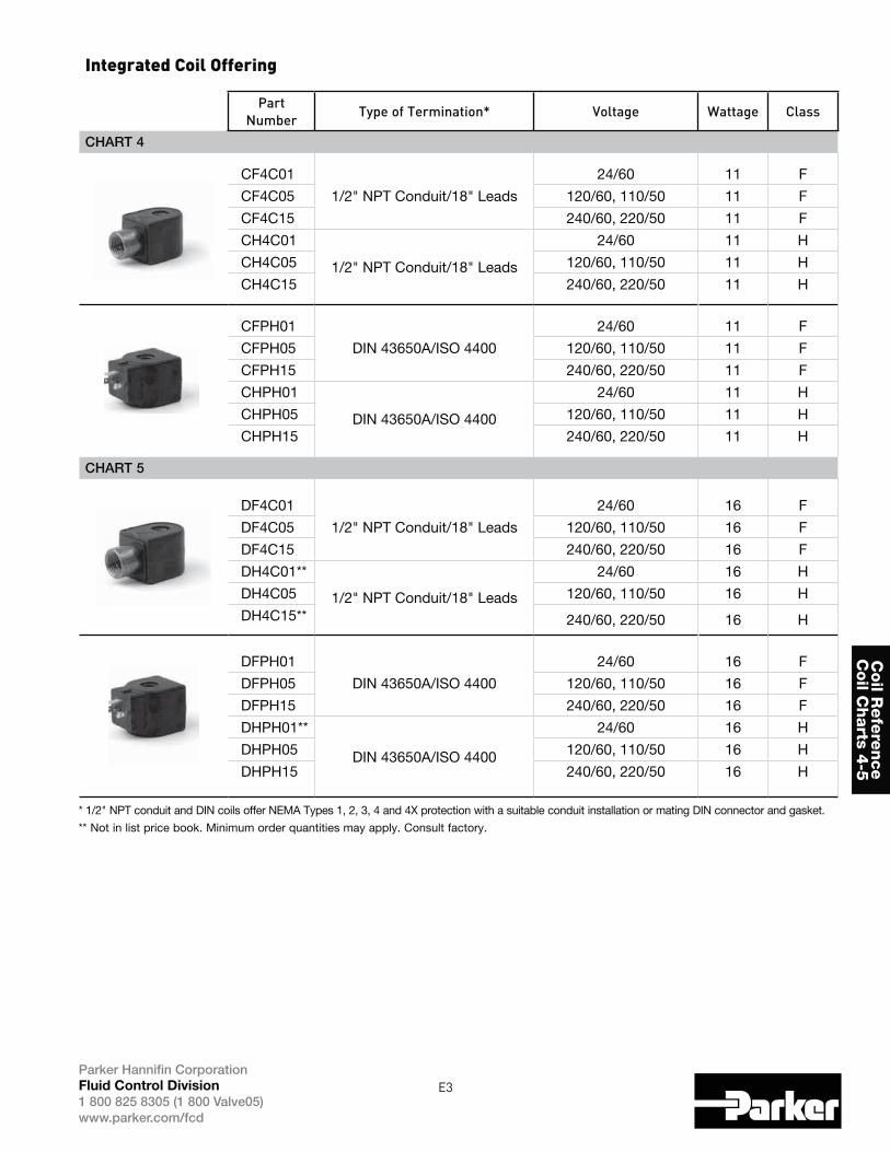
Integrated Coil Offering
Part
NumberType of Termination* Voltage Wattage Class
CHART 4
CF4C01
1/2" NPT Conduit/18" Leads
24/60 11 F
CF4C05 120/60, 110/50 11 F
CF4C15 240/60, 220/50 11 F
CH4C01
1/2" NPT Conduit/18" Leads
24/60 11 H
CH4C05 120/60, 110/50 11 H
CH4C15 240/60, 220/50 11 H
CFPH01
DIN 43650A/ISO 4400
24/60 11 F
CFPH05 120/60, 110/50 11 F
CFPH15 240/60, 220/50 11 F
CHPH01
DIN 43650A/ISO 4400
24/60 11 H
CHPH05 120/60, 110/50 11 H
CHPH15 240/60, 220/50 11 H
CHART 5
DF4C01
1/2" NPT Conduit/18" Leads
24/60 16 F
DF4C05 120/60, 110/50 16 F
DF4C15 240/60, 220/50 16 F
DH4C01**
1/2" NPT Conduit/18" Leads
24/60 16 H
DH4C05 120/60, 110/50 16 H
DH4C15** 240/60, 220/50 16 H
DFPH01
DIN 43650A/ISO 4400
24/60 16 F
DFPH05 120/60, 110/50 16 F
DFPH15 240/60, 220/50 16 F
DHPH01**
DIN 43650A/ISO 4400
24/60 16 H
DHPH05 120/60, 110/50 16 H
DHPH15 240/60, 220/50 16 H
* 1/2" NPT conduit and DIN coils offer NEMA Types 1, 2, 3, 4 and 4X protection with a suitable conduit installation or mating DIN connector and gasket.
** Not in list price book. Minimum order quantities may apply. Consult factory.
E4Parker Hannifin CorporationFluid Control Division
1 800 825 8305 (1 800 Valve05)www.parker.com/fcd
Coil
Refe
rence
Coil
Chart
6
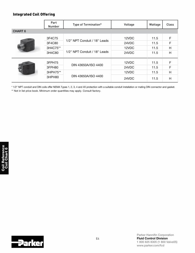
Integrated Coil Offering
Part
NumberType of Termination* Voltage Wattage Class
CHART 6
3F4C751/2" NPT Conduit / 18" Leads
12VDC 11.5 F
3F4C80 24VDC 11.5 F
3H4C75**1/2" NPT Conduit / 18" Leads
12VDC 11.5 H
3H4C80 24VDC 11.5 H
3FPH75DIN 43650A/ISO 4400
12VDC 11.5 F
3FPH80 24VDC 11.5 F
3HPH75**DIN 43650A/ISO 4400
12VDC 11.5 H
3HPH80 24VDC 11.5 H
* 1/2" NPT conduit and DIN coils offer NEMA Types 1, 2, 3, 4 and 4X protection with a suitable conduit installation or mating DIN connector and gasket.
** Not in list price book. Minimum order quantities may apply. Consult factory.
E5Parker Hannifin CorporationFluid Control Division
1 800 825 8305 (1 800 Valve05)www.parker.com/fcd
Coil R
efe
rence
Coil C
harts 1
-6
Additional Coil Options for Charts 1-6 (Below are replacement coils only; no enclosures except as noted)
Part
NumberType of Termination Voltage Wattage Class
AFSB01
NEMA 1 Splice Box w/ 6" Leaded Coil
24/60 6 F
AFSB05 120/60, 110/50 6 F
AFSB15 240/60, 220/50 6 F
BFSB01*
NEMA 1 Splice Box w/ 6" Leaded Coil
24/60 10.2 F
BFSB05* 120/60, 110/50 10.2 F
BFSB15* 240/60, 220/50 10.2 F
CFSB01
NEMA 1 Splice Box w/ 6" Leaded Coil
24/60 11 F
CFSB05 120/60, 110/50 11 F
CFSB15 240/60, 220/50 11 F
DFSB01*
NEMA 1 Splice Box w/ 6" Leaded Coil
24/60 16 F
DFSB05 120/60, 110/50 16 F
DFSB15* 240/60, 220/50 16 F
1FSB75**NEMA 1 Splice Box w/ 6" Leaded Coil
12 VDC 9.5 F
1FSB80 24 VDC 9.5 F
3FSB75NEMA 1 Splice Box w/ 6" Leaded Coil
12 VDC 11.5 F
3FSB80 24 VDC 11.5 F
AFEC01*18" Leaded Coil for NEMA 7/9 hazardous location enclosure
24/60 6 F
AFEC05 120/60, 110/50 6 F
AFEC15 240/60, 220/50 6 F
BFEC0118" Leaded Coil for NEMA 7/9 hazardous location enclosure
24/60 10.2 F
BFEC05 120/60, 110/50 10.2 F
BFEC15 240/60, 220/50 10.2 F
CFEC01*18" Leaded Coil for NEMA 7/9 hazardous location enclosure
24/60 11 F
CFEC05 120/60, 110/50 11 F
CFEC15 240/60, 220/50 11 F
DFEC01*18" Leaded Coil for NEMA 7/9 hazardous location enclosure
24/60 16 F
DFEC05 120/60, 110/50 16 F
DFEC15 240/60, 220/50 16 F
1FEC75* 18" Leaded Coil for NEMA 7/9 hazardous location enclosure
12 VDC 9.5 F
1FEC80 24 VDC 9.5 F
3FEC75 18" Leaded Coil for NEMA 7/9 hazardous location enclosure
12 VDC 11.5 F
3FEC80 24 VDC 11.5 F
* Not in list price book. Minimum order quantities may apply. Consult factory.
E6Parker Hannifin CorporationFluid Control Division
1 800 825 8305 (1 800 Valve05)www.parker.com/fcd
Coil
Refe
rence
Coil
Chart
s 1-6
DIN Electrical Accessories for Charts 1-6
Part
NumberDescription
ELECD1 Cable Gland DIN Plug
ELECD2 1/2" Conduit DIN Plug
Additional Coil Options for Charts 1-6 Cont. (Below replacement coils only, no enclosures)
Part
NumberType of Termination Voltage Wattage Class
AHEC01*AHEC05*AHEC15*
18" Leaded Coil for NEMA 7/9 hazardous location enclosure24/60
120/60, 110/50240/60, 220/50
6 H
BHEC01*BHEC05*BHEC15*
18" Leaded Coil for NEMA 7/9 hazardous location enclosure24/60
120/60, 110/50240/60, 220/50
10.2 H
CHEC01
18" Leaded Coil for NEMA 7/9 hazardous location enclosure
24/60
11 HCHEC05 120/60, 110/50
CHEC15 240/60, 220/50
DHEC01DHEC05DHEC15
18" Leaded Coil for NEMA 7/9 hazardous location enclosure
24/60
16 H120/60, 110/50
240/60, 220/50
IHEC75IHEC80 18" Leaded Coil for NEMA 7/9 hazardous location enclosure
12 VDC9.5 H
24 VDC
3HEC753HEC80 18" Leaded Coil for NEMA 7/9 hazardous location enclosure
12 VDC11.5 H
24 VDC
* Not in list price book. Minimum order quantities may apply. Consult factory.
E7Parker Hannifin CorporationFluid Control Division
1 800 825 8305 (1 800 Valve05)www.parker.com/fcd
Coil R
efe
rence
Coil C
harts 1
-6
1.640
R1.096
1.350
.430.640
1.330
2.188
Coil Charts 1-6 Integrated Coil Dimensional Values
1.63
1.67
.89
.48
.69
.674
.674
1.35
.189
Ax4Cxx AxPHxx
1.95
�
.77
1.61
1.10
2.04
.476
.71
.65
.77
1.53Cx4Cxx CxPHxx
E8Parker Hannifin CorporationFluid Control Division
1 800 825 8305 (1 800 Valve05)www.parker.com/fcd
Coil
Refe
rence
Coil
Chart
s 1-6
Valves using coil charts 1-6 (Gold RingTM brand) Part Numbering Information: Reference ONLY
1 & 2 3 4 5 6 7 8 9 & 10 11
Connection
Size
Connection
Type
Construction Operation Body
Material
Trim Orifice Size Current
Design Series
Designations
02 1/8"
04 1/4"
06 3/8"
08 1/2"
12 3/4"
16 1"
20 1 1/4"
24 1 1/2"
32 2"
48 3"
F Female Pipe Thread NPT
2 2-way
3 3-way
4 4-way
H Diaphragm, Hung
5 Diaphragm, Pivoted Edge
S Steam
0 Direct Acting
2 Diaphragm Center pilot
3 Diaphragm Hung
4 Diaphragm Offset pilot
5 Diaphragm Pivoted Edge
6 Piston
8 Piston piloted
C Normally Closed
O Normally Open
U Universal
S 4-Way Single Solenoid
1 Brass (Bar Stock)
2 Brass (Forging)
3 303 Stainless Steel (Bar)
5 Brass Nickel Plate
6 316 Stainless Steel (Cast)
7 Aluminum (Bar Stock)
8 316 Stainless Steel (Bar)
9 Bronze (Cast)
1 NBR
2 FKM
3 EPDM
4 PTFE
5 Urethane
6 CR
8 FDA EPR
9 Kalrez
D Delrin
K KEL F
Valve orifice diameter in 1/64-inch increments. Example: a 1/2-inch orifice diameter has an orifice size designation of 32.
ALERT: Table is for interpreting product specifications only. Consult Parker Fluid Control Division
for available combinations not shown in catalog.
E9Parker Hannifin CorporationFluid Control Division
1 800 825 8305 (1 800 Valve05)www.parker.com/fcd
Coil R
efe
rence
Coil C
harts 1
-6
Valves using coil charts 1-6 (Gold RingTM brand)
12 13 14 15 16 & 17
Coil Wattage
AC (nominal)
Coil Wattage
DC (normal)
Coil Class Solenoid Enclosure Coil Termination Coil
Voltage AC
Coil
Voltage
DC
A 6 Watts
B 10.2 Watts
C 11 Watts
D 16 Watts
1 9.5 Watts
3 11.5 Watts
F Standard (Class 155)
H High Temperature (Class 180)
E Explosion-Proof/Watertight
G Type 1 Gen. Purpose
M 316 SS Explosion-Proof/Watertight
O Open Frame
P Epoxy Encapsulated
S Type 1 Splice Box
U 316 SS Explosion-Proof/Watertight
W Submersible Splice Box
Y Explosion-Proof/Watertight with Ground Lead
Z Grounded M
4 Type 4, 4X
C 18" Leads (Standard)
H DIN
K Screw
S Spade
01 24/60
02 24/50
05 110/50 120/60
10 208/60
15 220/50 240/60
20 440/50 480/60
41 24/60 rectified
42 120/60 rectified
44 240/60 rectified
51 120-240/60
53 240-480/60
70
75
80
90
95
6
12
24
120
125
ALERT: Table is for interpreting product specifications only. Consult Parker Fluid Control Division
for available combinations not shown in this catalog.
E10Parker Hannifin CorporationFluid Control Division
1 800 825 8305 (1 800 Valve05)www.parker.com/fcd
Coil
Refe
rence
Coil
Chart
7
Integrated Coil Offering
Part Number Type of Termination* Voltage Wattage Class
CHART 7
C111B2
1/2" NPT Conduit / 18" Leads
24/60
10 F
C111P3 120/60, 110/50
C111Q3 240/60, 220/50
C111C1 12VDC
C111C2 24VDC
C111C6 120VDC
C222B2
1/2" NPT Conduit / 18" Leads
24/60
10 H
C222P3 120/60, 110/50
C222Q3 240/60, 220/50
C222C1 12VDC
C222C2 24VDC
C222C6 120VDC
D100B2
DIN 43650A/ISO 4400
24/60
10 F
D100P3 120/60, 110/50
D100Q3 240/60, 220/50
D100C1 12VDC
D100C2 24VDC
D100C6** 120VDC
D200B2
DIN 43650A/ISO 4400
24/60
10 H
D200P3 120/60, 110/50
D200Q3 240/60, 220/50
D200C1 12VDC
D200C2 24VDC
D200C6** 120VDC
* 1/2" NPT conduit and DIN coils offer NEMA Types 1, 2, 3, 4 and 4X protection with a suitable conduit installation or mating DIN connector and gasket.
** Not in list price book. Minimum order quantities may apply. Consult factory.
E11Parker Hannifin CorporationFluid Control Division
1 800 825 8305 (1 800 Valve05)www.parker.com/fcd
Coil R
efe
rence
Coil C
hart 7
Integrated Coil Offering
Part Number Type of Termination Voltage Wattage Class
CHART 7 (Continued)
L111B2
18" Leads
24/60
10 F
L111P3 120/60, 110/50
L111Q3 240/60, 220/50
L111C1 12VDC
L111C2 24VDC
L111C6* 120VDC
L222B2*
18" Leads
24/60
10 H
L222P3 120/60, 110/50
L222Q3 240/60, 220/50
L222C1 12VDC
L222C2 24VDC
L222C6 120VDC
T100B2*
1/4" Tab (spade)
24/60
10 F
T100P3 120/60, 110/50
T100Q3 240/60, 220/50
T100C1 12VDC
T100C2* 24VDC
T100C6* 120VDC
S100B2*
Screw Terminal
24/60
10 F
S100P3 120/60, 110/50
S100Q3 220/50, 240/60
S100C1* 12VDC
S100C2 24VDC
S100C6 120VDC
S200B2
Screw Terminal
24/60
10 H
S200P3 120/60, 110/50
S200Q3* 240/60, 220/50
S200C1* 12VDC
S200C2* 24VDC
S200C6* 120VDC
* Not in list price book. Minimum order quantities may apply. Consult factory
E12Parker Hannifin CorporationFluid Control Division
1 800 825 8305 (1 800 Valve05)www.parker.com/fcd
Coil
Refe
rence
Coil
Chart
7
Integrated Coil Offering
Part Number Type of Termination* Voltage Wattage Class
CHART 7 (Continued)
H111B2**
UL Hazardous Locations NEMA Type 7/9 w/ 18" Leaded Coil
24/60
10 F
H111P3 120/160, 110/50
H111Q3 240/60, 220/50
H111C1 12VDC
H111C2 24VDC
H111C6** 120VDC
H222B2**
UL Hazardous Locations NEMA Type 7/9 w/ 18" Leaded Coil
24/60
10 H
H222P3 120/60, 110/50
H222Q3 240/60, 220/50
H222C1** 12VDC
H222C2 24VDC
H222C6 120VDC
* Hazardous location coil approvals: Class I, Div 1 & 2, Groups A, B, C, D; Class II, Div 1 & 2, Groups E,F,G; Class III, Div 1.
Additional Coil Options for Chart 7 (Below are replacement coils only, no enclosures)
Part Number Type of Termination Voltage Wattage Class
J111B2
Molded coil w/ 18" Leads
24/60
10 F
J111P3 120/60, 110/50
J111Q3 240/60, 220/50
J111C1 12VDC
J111C2 24VDC
J111C6** 120VDC
J222B2**
Molded coil w/ 18" Leads
24/60
10 H
J222P3 120/60, 220/50
J222Q3** 240/60, 220/50
J222C1 12VDC
J222C2** 24VDC
J222C6** 120VDC
** Not in list price book. Minimum order quantities may apply. Consult factory.
E13Parker Hannifin CorporationFluid Control Division
1 800 825 8305 (1 800 Valve05)www.parker.com/fcd
Coil R
efe
rence
Coil C
hart 8
Integrated Coil Offering
Part Number Type of Termination* Voltage Wattage Class
CHART 8
C322B2
1/2" NPT Conduit /18" Leads
24/60
22 H
C322P3 120/60, 110/50
C322Q3 240/60, 220/50
C322C1 12VDC
C322C2 24VDC
C322C6** 120VDC
D300B2**
DIN 43650A/ISO 4400
24/60
22 H
D300P3 120/60, 110/50
D300Q3 240/60, 220/50
D300C1 12VDC
D300C2 24VDC
D300C6** 120VDCL322B2**
1/2" NPT Conduit /18" Leads
24/60
22 H
L322P3 110/50, 120/60L322Q3 220/50, 240/60L322C1 12VDCL322C2 24VDCL322C6** 120VDCS300B2**
Screw Terminal
24/60
22 H
S300P3 120/60, 110/50S300Q3** 240/60, 220/50S300C1** 12VDCS300C2** 24VDCS300C6** 120VDC
* 1/2" NPT conduit and DIN coils offer NEMA Types 1, 2, 3, 4 and 4X protection with a suitable conduit installation or mating DIN connector and gasket.
** Not in list price book. Minimum order quantities may apply. Consult factory.
E14Parker Hannifin CorporationFluid Control Division
1 800 825 8305 (1 800 Valve05)www.parker.com/fcd
Coil
Refe
rence
Coil
Chart
8
J322B2**
Molded coil w/ 18" Leads
24/60
22 H
J322P3 120/60, 110/50
J322Q3** 240/60, 220/50
J322C1 12VDC
J322C2 24VDC
J322C6** 120VDC
* Hazardous location coil approvals: Class I, Din I & 2, Groups A,B,C,D; Class II, Div 1 & 2, Groups E, F, G; Class IV, Div 1
** Not in list price book. Minimum order quantities may apply. Consult factory.
Coil Options for Chart 8 cont. (Below replacement coils only, no enclosures)
Part Number Type of Termination* Voltage Wattage Class
H322B2
UL Hazardous Locations NEMA Type 7 & 9 w/ 18" Leaded Coil
24/60
22 H
H322P3 120/60, 110/50
H322Q3 240/60, 220/50
H322C1 12VDC
H322C2 24VDC
H322C6** 120VDC
* Hazardous location coil approvals: Class I, Din I & 2, Groups A,B,C,D; Class II, Div 1 & 2, Groups E, F, G; Class IV, Div 1
** Not in list price book. Minimum order quantities may apply. Consult factory.
Part Number Type of Termination Voltage Wattage Class
Additional Coil Options for Chart 8 (Below are replacement coils only, no enclosures)
E15Parker Hannifin CorporationFluid Control Division
1 800 825 8305 (1 800 Valve05)www.parker.com/fcd
Coil R
efe
rence
Coil C
harts 7
-8
1.62
1.95
1.53
1.25
�
.77
1.61
1.10
2.04
.476
.71
.65
.77
1.53
1.61
2.11
1.12
.35
.75
.25
.17
.77
1.53
1.30
2.23
1.60
.35
.21
.77
1.53
.84
1.53
1.61
2.151.21 .78
.36
.48
.66
q
#8-32 SCREW
Coil Charts 7, 8, 10 & 11 Integrated Coil Dimensional Values
C111xx, H111xx,C222xx, H222xx,C322xx, H322xx
D100xxD200xxD300xx
L100xx L222xxL322xx
T100xx S100xxS200xxS300xx
E16Parker Hannifin CorporationFluid Control Division
1 800 825 8305 (1 800 Valve05)www.parker.com/fcd
Coil
Refe
rence
Coil
Chart
s 7-8
Valves using coil charts 7, 8, 10, 11 & 12 (7000 Series Skinner™ Brand)Part Numbering Information: Reference ONLY1 2
Actuation
3
Functional
Type
4
Flow Pattern
5
Family
6
Body
Material
7
Threading
Process
Connection
8
Port
Size
(NPT)
9
Orifice
Code
10
Seals/
Elastomers
11 & 12
Mechanical
Options
7 0 Manual Reset
1 Direct Acting
2 Direct Lift
3 Pilot Operated Internal Pilot Supply
4 Pilot Operated External Pilot Supply
5 Remote Pressure Operated
6 Manual/Mech. Operated
2 Two-Way
3 Three-Way
4 Four-Way
2-Way Valves
1 Normally Closed
2 Normally Open pressure in/out of body
3 Multi/Dual purpose
9 Normally Open pressure in the body, pressure out the sleeve
3-Way Valves
1 Normally Closed
2 Normally Open pressure in/out of body
3 Multi/Dual Purpose
8 Diverting9 Normally Open
pressure in the sleeve, pressure out the body
4-Way Valves
1 2-position, single operator
2 3-position, dual operator center closed
3 3-position, dual operator center open
4 3-position, dual operator center open
6 2-position, dual operator bi-stable
7 2-position, dual operator bi-stable, with latching
1
2
3
4
5
6
7
8
9
E
F
G
K
L
T
X
A Aluminum
B Brass
L Noryl
M Zinc Die Cast
R 316 SS
S 430F SS
T Teflon
V 303 SS
A SAE
E Male NPT
F Flange
G BSP-Parallel
J Bib Fitting
K Direct Mount
N NPT(Female Nat’l Pipe thread)
P NPTF
R BSP-Taper
S Subbase Mounted
T Barbed Fitting
1 1/8"
2 1/4"
3 3/8"
4 1/2"
5 3/4"
6 1"
7 1 1/4" For K
8 1 1/2"
9 2"
For K in
Pos. 7
D M5
E #10-24
F #10-32
A
B
C
D
E
F
G
H
J
K
L
M
N
P
Q
R
S
T
U
V
0 thru 9
C CR
E EPDM
F PCTFE
K PFPM
L Nylon
M Metal
N NBR
R Ruby
T PTFE
U PTFE
V FKM
00 No Option
7A Momentary Manual Override
7C 7A + J1
7F Captured Exhaust Pilot
7G 7F + 7A
7H 7F + MO
7M Plugged Manual Override
A2 Silver Shading Ring
CB Cylinder “B” normally open to pressure inlet
C0 4-Step Variable Closing
ET Electrically Tripped / Manual Reset
J0 Pilot Exhaust Return Pipe
J1 Exhaust Adaptor Nut
M0 Manual Override
M5 Manual Override w/Exhaust Adaptor (M0 + J1)
MC Manual Override w/Var. Closing
MJ Manual Override w/Exhaust Return Pipe
MR Manual Override w/Main Stream Metering
N0 Cleaned for oxygen service
R1 Mainstream Metering
S0 Steam Service Rated
VR No Voltage Release / Manual Reset
W0 Anti-Water Hammer (fixed)
ALERT: Table is for interpreting product specifications only. Consult Parker Fluid Control Division
for available combinations not shown in this catalog.
E17Parker Hannifin CorporationFluid Control Division
1 800 825 8305 (1 800 Valve05)www.parker.com/fcd
Coil R
efe
rence
Coil C
harts 7
-8
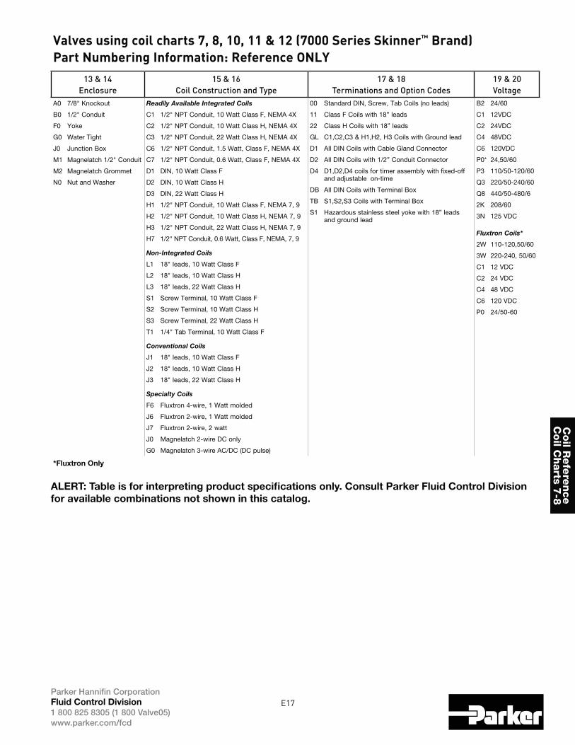
Valves using coil charts 7, 8, 10, 11 & 12 (7000 Series Skinner™ Brand)Part Numbering Information: Reference ONLY
13 & 14
Enclosure
15 & 16
Coil Construction and Type
17 & 18
Terminations and Option Codes
19 & 20
Voltage
A0
B0
F0
G0
J0
M1
M2
N0
7/8" Knockout
1/2" Conduit
Yoke
Water Tight
Junction Box
Magnelatch 1/2" Conduit
Magnelatch Grommet
Nut and Washer
Readily Available Integrated Coils
C1 1/2" NPT Conduit, 10 Watt Class F, NEMA 4X
C2 1/2" NPT Conduit, 10 Watt Class H, NEMA 4X
C3 1/2" NPT Conduit, 22 Watt Class H, NEMA 4X
C6 1/2" NPT Conduit, 1.5 Watt, Class F, NEMA 4X
C7 1/2" NPT Conduit, 0.6 Watt, Class F, NEMA 4X
D1 DIN, 10 Watt Class F
D2 DIN, 10 Watt Class H
D3 DIN, 22 Watt Class H
H1 1/2" NPT Conduit, 10 Watt Class F, NEMA 7, 9
H2 1/2" NPT Conduit, 10 Watt Class H, NEMA 7, 9
H3 1/2" NPT Conduit, 22 Watt Class H, NEMA 7, 9
H7 1/2" NPT Conduit, 0.6 Watt, Class F, NEMA, 7, 9
Non-Integrated Coils
L1 18" leads, 10 Watt Class F
L2 18" leads, 10 Watt Class H
L3 18" leads, 22 Watt Class H
S1 Screw Terminal, 10 Watt Class F
S2 Screw Terminal, 10 Watt Class H
S3 Screw Terminal, 22 Watt Class H
T1 1/4" Tab Terminal, 10 Watt Class F
Conventional Coils
J1 18" leads, 10 Watt Class F
J2 18" leads, 10 Watt Class H
J3 18" leads, 22 Watt Class H
Specialty Coils
F6 Fluxtron 4-wire, 1 Watt molded
J6 Fluxtron 2-wire, 1 Watt molded
J7 Fluxtron 2-wire, 2 watt
J0 Magnelatch 2-wire DC only
G0 Magnelatch 3-wire AC/DC (DC pulse)
00 Standard DIN, Screw, Tab Coils (no leads)
11 Class F Coils with 18” leads
22 Class H Coils with 18” leads
GL C1,C2,C3 & H1,H2, H3 Coils with Ground lead
D1 All DIN Coils with Cable Gland Connector
D2 All DIN Coils with 1/2” Conduit Connector
D4 D1,D2,D4 coils for timer assembly with fixed-off and adjustable on-time
DB All DIN Coils with Terminal Box
TB S1,S2,S3 Coils with Terminal Box
S1 Hazardous stainless steel yoke with 18” leads and ground lead
B2 24/60
C1 12VDC
C2 24VDC
C4 48VDC
C6 120VDC
P0* 24,50/60
P3 110/50-120/60
Q3 220/50-240/60
Q8 440/50-480/6
2K 208/60
3N 125 VDC
Fluxtron Coils*
2W 110-120,50/60
3W 220-240, 50/60
C1 12 VDC
C2 24 VDC
C4 48 VDC
C6 120 VDC
P0 24/50-60
*Fluxtron Only
ALERT: Table is for interpreting product specifications only. Consult Parker Fluid Control Division
for available combinations not shown in this catalog.
E18Parker Hannifin CorporationFluid Control Division
1 800 825 8305 (1 800 Valve05)www.parker.com/fcd
Coil
Refe
rence
Coil
Chart
s 7-8
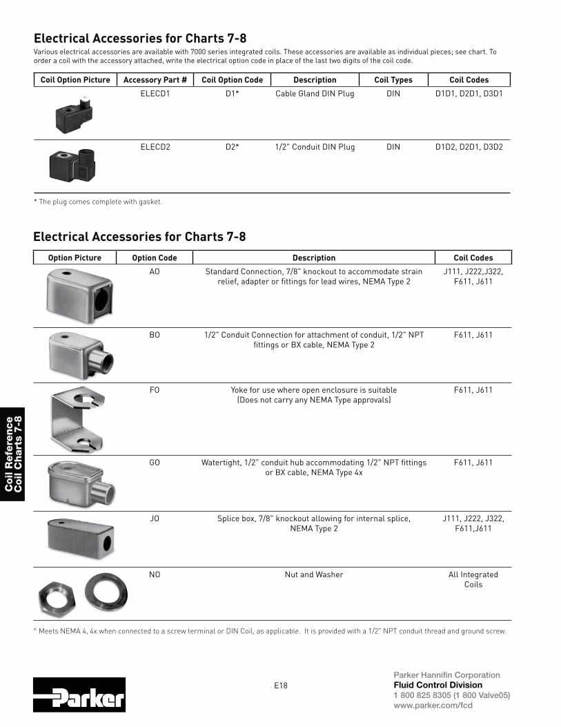
Electrical Accessories for Charts 7-8Various electrical accessories are available with 7000 series integrated coils. These accessories are available as individual pieces; see chart. To order a coil with the accessory attached, write the electrical option code in place of the last two digits of the coil code.
Coil Option Picture Accessory Part # Coil Option Code Description Coil Types Coil Codes
ELECD1 D1* Cable Gland DIN Plug DIN D1D1, D2D1, D3D1
ELECD2 D2* 1/2" Conduit DIN Plug DIN D1D2, D2D1, D3D2
* The plug comes complete with gasket.
^ Meets NEMA 4, 4x when connected to a screw terminal or DIN Coil, as applicable. It is provided with a 1/2" NPT conduit thread and ground screw.
Electrical Accessories for Charts 7-8Option Picture Option Code Description Coil Codes
AO Standard Connection, 7/8" knockout to accommodate strain relief, adapter or fittings for lead wires, NEMA Type 2
J111, J222,J322, F611, J611
BO 1/2" Conduit Connection for attachment of conduit, 1/2" NPT fittings or BX cable, NEMA Type 2
F611, J611
FO Yoke for use where open enclosure is suitable (Does not carry any NEMA Type approvals)
F611, J611
GO Watertight, 1/2" conduit hub accommodating 1/2" NPT fittings or BX cable, NEMA Type 4x
F611, J611
JO Splice box, 7/8" knockout allowing for internal splice, NEMA Type 2
J111, J222, J322, F611,J611
NO Nut and Washer All Integrated Coils
E19Parker Hannifin CorporationFluid Control Division
1 800 825 8305 (1 800 Valve05)www.parker.com/fcd
Coil R
efe
rence
Coil C
harts 7
-8
About the IECEx
IECEx System ObjectiveThe objective of the IECEx System is to facilitate international trade in equipment and services for use in explosive atmospheres, while maintaining the required level of safety:
costs to manufacturer
product assessment process
-dence in equipment and services
What is an Ex area?Ex areas can be known by different names such as “Hazardous Locations”, “Hazardous Areas” “Explosive Atmospheres”, and the like and relate to areas where flammable liquids, vapours, gases or combustible dusts are likely to occur in quantities
The modern day automation of industry has meant an increased need to use equipment in Ex areas. Such equipment is termed “Ex equipment”
International Electrotechnical Commission1. The IECEx Certified Equipment SchemeThis IECEx Scheme is an Interna-
product that meets the requirements of International Standards, e.g. IEC Standards prepared by TC 31.
Scheme provides both:
Conformity that requires manufac-turers to successfully complete:-
samples for compliance with Standards
manufacturers premises
manufacturers premises
or
b) A “fast-track” process for countries where regulations still require the issuing of national Ex
achieved by way of global accep-tance of IECEx equipment Test and Assessment Reports.
3. The Ex Mark of Conformity SystemThis IECEx System is an International Conformity System where a Mark of Conformity will be granted by
located in IECEx participating countries for equipment that is
Conformity and hence has been
tested and manufactured under systems that are under ongoing surveillance by ExCBs.
It will help governments, safety regulators, and industry to have greater assurance that the equipment being operated or supplied for use in areas where flammable gases and vapours and combustible dusts (termed explosive atmospheres) are present, meet the world’s most respected and vigorous safety standards.
The Mark shall only be placed on products or on packaging and promotional material covered by a
issued in accordance with the IECEx System rules.
4. IECEx Certified Persons SchemeThis IECEx Scheme is an Interna-tional Conformity Scheme that provides the global Ex industries with a single system for the assessment
the competency prerequisites needed to properly implement the safety requirements based on the suite of IEC International Standards covering explosive atmospheres, e.g. the IEC 60079 and IEC 61241 series of standards.
provides the international Ex indus-
is transportable across borders.
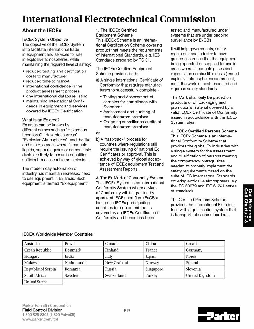
IECEX Worldwide Member Countries
Australia Brazil Canada China Croatia
Czech Republic Denmark Finland France Germany
Hungary India Italy Japan Korea
Malaysia Netherlands New Zealand Norway Poland
Republic of Serbia Romania Russia Singapore Slovenia
South Africa Sweden Switzerland Turkey United Kigndom
United States
E20Parker Hannifin CorporationFluid Control Division
1 800 825 8305 (1 800 Valve05)www.parker.com/fcd
Coil
Refe
rence
Coil
Chart
s 7-8
2.1 Explosive gas environments Mixture with air, under atmospheric conditions, of flammable substances in the form of gases, vapor, mists or dusts in which, after combustion has occurred, combustion spreads to the entire unburned mixture.
2.2 Hazardous areas A hazardous area is an area in which an explosive gas environment is present, or may be expected to be present, in quantities such as to require special precautions for construction, installation and use of electrical apparatus.
2.3. Ingredients for an explosion When combustible materials are mixed with air, an explosive mixture is produced. Danger of explosion therefore exists wherever these hazardous materials are handled: such a condition is to be found on the biggest chemical plant as well as at the smallest filling station.
Nowadays with the use of electronic and electrical instrumentation in process control, the risk of combustion by electrical energy has increased sharply.
To protect personnel and expensive equipment special precautions should be taken to prevent combustion of those dangerous substances. Condi-tions likely to ignite explosive mixtures are as follows:
when circuits are opened and closed (e.g. relay contacts)
current or by faulty apparatus.
charged components.
Parker Fluid Control Division is pleased to announce the addition of several
for dust. Coil marking complies with the updated standards. Declaration of Conformity documents for specific part numbers are provided with the electrical product and also provided upon request.
Background:
initiative undertaken to ensure the safety of products used in potentially
mandate that all products that could provide ignition to a potentially explosive atmosphere be produced to specific requirements, under controlled condi-tions, by a manufacturer certified compliant to the directive by an independent notification body. Certi-fication requires approval of the entire quality management system to the
requirements imposed for product verifi-cations, testing and records thereof.
-zation overseeing the development of international standards for electrical, electronic & related technologies. The
International Certification for manufac-turers of electrical equipment intended for explosive atmospheres thereby eliminating the need for multiple national certifications in all participating countries. Any recognized certified body can provide a product Certificate of Conformity stating the product design
and the product is manufactured under a quality plan assessed by an accepted
scheme is becoming internationally accepted.
accepted certification body (ACB) and
States has recently integrated both the zone and division system requirements into their respective installation codes.
The Canadian Standards Association
All new installations follow the three-zone area classification while following the two-division system for existing facilities. To reflect the new system, CSA
The introduction of zones area classifica-tions in North America as an accepted alternative to divisions sees the intro-
continued acceptance on a global basis.
standards apply to hazardous environ-ments from intrinsically safe apparatus to flameproof control systems to increased safety requirements.
2.4 Zones The hazardous areas are classified in zones based on the frequency of the occurrence and the duration of an explosive gas environment as follows:
An area in which an explosive gas environment is present continuously or is present for long periods Type of protection: ia - intrinsic Safety
An area in which an explosive gas environment is likely to occur in normal operations. Type of protection: d - flameproof enclosure, e - increased safety, ib - intrinsic safety, m - encap-sulation
An area in which an explosive gas environment is not likely to occur and if it does occur it will exist for a short period only. Type of protection: n -
Definitions (ref. IEC 60079-10)
ATEX/IECEx General Information
E21Parker Hannifin CorporationFluid Control Division
1 800 825 8305 (1 800 Valve05)www.parker.com/fcd
Coil R
efe
rence
Coil C
harts 7
-8
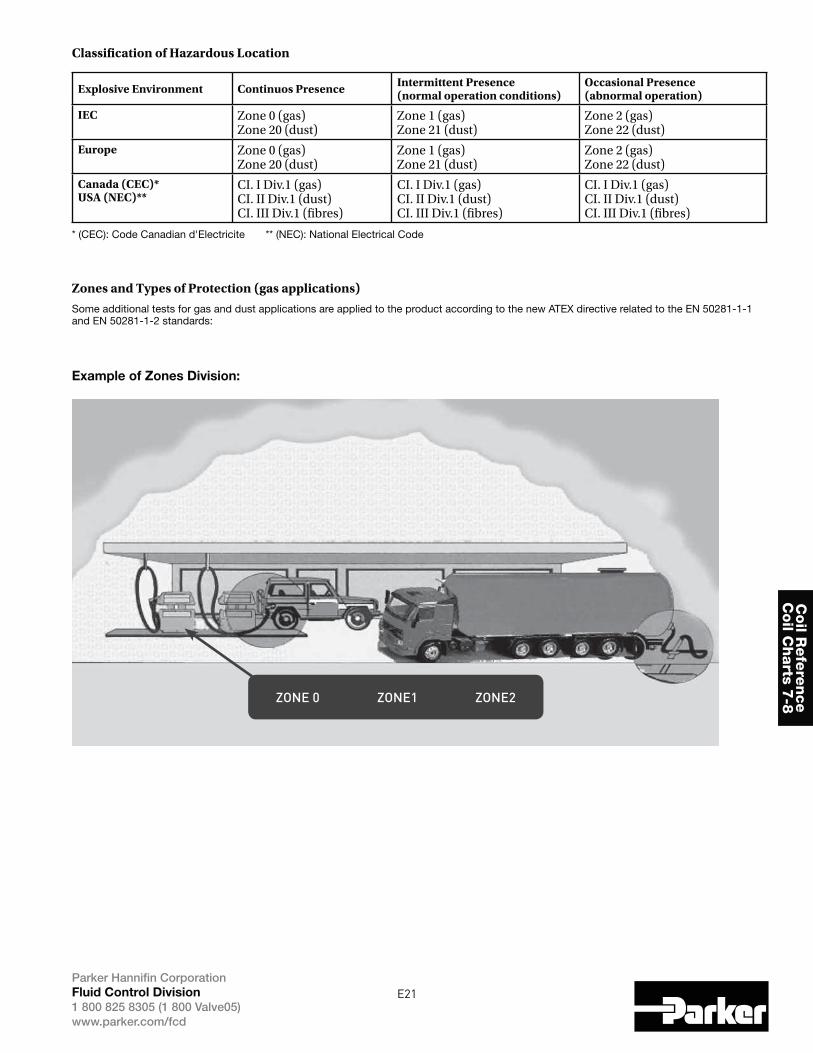
Classification of Hazardous Location
Explosive Environment Continuos Presence Intermittent Presence (normal operation conditions)
Occasional Presence (abnormal operation)
IEC
Europe
Canada (CEC)*USA (NEC)**
* (CEC): Code Canadian d'Electricite ** (NEC): National Electrical Code
Zones and Types of Protection (gas applications)
Some additional tests for gas and dust applications are applied to the product according to the new ATEX directive related to the EN 50281-1-1 and EN 50281-1-2 standards:
Example of Zones Division:
ZONE 0 ZONE1 ZONE2
E22Parker Hannifin CorporationFluid Control Division
1 800 825 8305 (1 800 Valve05)www.parker.com/fcd
Coil
Refe
rence
Coil
Chart
s 7-8
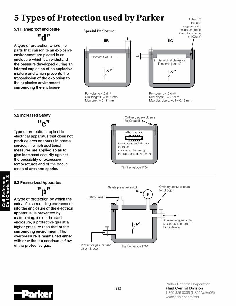
5 Types of Protection used by Parker5.1 Flameproof enclosure
"d"A type of protection where the parts that can ignite an explosiveenvironment are placed in anenclosure which can withstand the pressure developed during aninternal explosion of an explosivemixture and which prevents thetransmission of the explosion to the explosive environment surrounding the enclosure.
5.2 Increased Safety
"e"Type of protection applied toelectrical apparatus that does notproduce arcs or sparks in normalservice, in which additionalmeasures are applied so as to give increased security against the possibility of excessive temperatures and of the occur-rence of arcs and sparks.
5.3 Pressurized Apparatus
"p"A type of protection by which the entry of a surrounding environment into the enclosure of the electrical apparatus, is prevented by maintaining, inside the said enclosure, a protective gas at a higher pressure than that of the surrounding environment. The overpressure is maintained either with or without a continuous flow of the protective gas.
IIB
Special Enclosure
Contact Seal IIB ii diametrical clearance
Threaded joint IIC
At least 5
threads
engaged min.
height engaged
8mm for volume
> 100cm3
For volume > 2 dm3
Mini lenght L = 12.5 mm
Max gap i = 0.15 mm
For volume > 2 dm3
Mini lenght L = 25 mm
Max dia. clearance i = 0.15 mm
Ordinary screw closure
for Group II
Ordinary screw closure
for Group II
Scavenging gas outlet
to safe zone or anti-
flame device
Safety valve
Protective gas, purified
air or nitrogen
Safety pressure switch
Tight envelope IP54
Tight envelope IP40
without spark
Creepages and air gap
distance
conductor fastening
insulator category heating
IICL
P
L
E23Parker Hannifin CorporationFluid Control Division
1 800 825 8305 (1 800 Valve05)www.parker.com/fcd
Coil R
efe
rence
Coil C
harts 7
-8
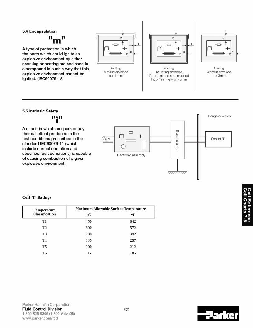
5.4 Encapsulation
"m"A type of protection in which the parts which could ignite an explosive environment by either sparking or heating are enclosed in a compound in such a way that this explosive environment cannot be ignited. (IEC60079-18)
5.5 Intrinsic Safety
"i"A circuit in which no spark or any thermal effect produced in the test conditions prescribed in the standard IEC60079-11 (which include normal operation and specified fault conditions) is capable of causing combustion of a given explosive environment.
Potting
Metallic envelope
e > 1 mm
Safe area
Electronic assembly
Sensor "i"
Zene b
arr
ier
[i]
230 V
Dangerous area
Potting
Insulating envelope
If p > 1 mm, e non-imposed
If p > 1mm, e + p > 3mm
Casing
Without envelope
e > 3mm
Coil "T" Ratings
Temperature Classification
Maximum Allowable Surface Temperature
ºC ºF
T3
T4
E24Parker Hannifin CorporationFluid Control Division
1 800 825 8305 (1 800 Valve05)www.parker.com/fcd
Coil
Refe
rence
Coil
Chart
s 7-8
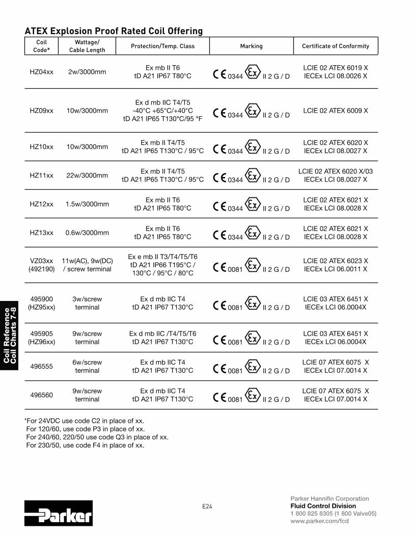
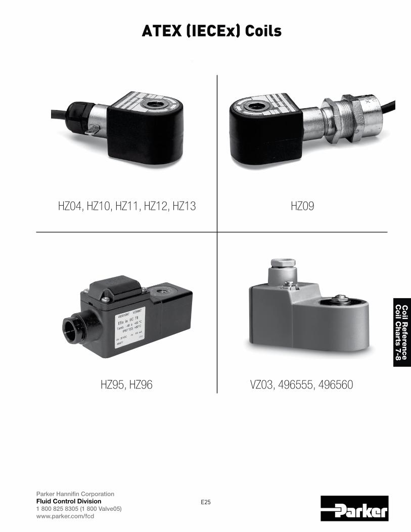
ATEX Explosion Proof Rated Coil OfferingCoil
Code*
Wattage/
Cable LengthProtection/Temp. Class Marking Certificate of Conformity
HZ04xx 2w/3000mmEx mb II T6
tD A21 IP67 T80°C 0344 II 2 G / DLCIE 02 ATEX 6019 X IECEx LCI 08.0026 X
HZ09xx 10w/3000mmEx d mb IIC T4/T5
-40°C +65°C/+40°CtD A21 IP65 T130°C/95 °F 0344 II 2 G / D
LCIE 02 ATEX 6009 X
HZ10xx 10w/3000mmEx mb II T4/T5
tD A21 IP65 T130°C / 95°C 0344 II 2 G / DLCIE 02 ATEX 6020 X IECEx LCI 08.0027 X
HZ11xx 22w/3000mmEx mb II T4/T5
tD A21 IP65 T130°C / 95°C 0344 II 2 G / DLCIE 02 ATEX 6020 X/03
IECEx LCI 08.0027 X
HZ12xx 1.5w/3000mmEx mb II T6
tD A21 IP65 T80°C 0344 II 2 G / DLCIE 02 ATEX 6021 X IECEx LCI 08.0028 X
HZ13xx 0.6w/3000mmEx mb II T6
tD A21 IP65 T80°C 0344 II 2 G / DLCIE 02 ATEX 6021 X IECEx LCI 08.0028 X
VZ03xx(492190)
11w(AC), 9w(DC) / screw terminal
Ex e mb II T3/T4/T5/T6tD A21 IP66 T195°C / 130°C / 95°C / 80°C 0081 II 2 G / D
LCIE 02 ATEX 6023 X IECEx LCI 06.0011 X
495900(HZ95xx)
3w/screw terminal
Ex d mb IIC T4tD A21 IP67 T130°C 0081 II 2 G / D
LCIE 03 ATEX 6451 X IECEx LCI 06.0004X
495905(HZ96xx)
9w/screw terminal
Ex d mb IIC /T4/T5/T6 tD A21 IP67 T130°C 0081 II 2 G / D
LCIE 03 ATEX 6451 X IECEx LCI 06.0004X
4965556w/screw terminal
Ex d mb IIC T4tD A21 IP67 T130°C 0081 II 2 G / D
LCIE 07 ATEX 6075 X IECEx LCI 07.0014 X
4965609w/screw terminal
Ex d mb IIC T4tD A21 IP67 T130°C 0081 II 2 G / D
LCIE 07 ATEX 6075 X IECEx LCI 07.0014 X
**For 24VDC use code C2 in place of xx. For 120/60, use code P3 in place of xx. For 240/60, 220/50 use code Q3 in place of xx. For 230/50, use code F4 in place of xx.
E25Parker Hannifin CorporationFluid Control Division
1 800 825 8305 (1 800 Valve05)www.parker.com/fcd
Coil R
efe
rence
Coil C
harts 7
-8
ATEX (IECEx) Coils
HZ04, HZ10, HZ11, HZ12, HZ13 HZ09
HZ95, HZ96 VZ03, 496555, 496560
E26Parker Hannifin CorporationFluid Control Division
1 800 825 8305 (1 800 Valve05)www.parker.com/fcd
Coil
Refe
rence
Coil
Chart
s 7-8
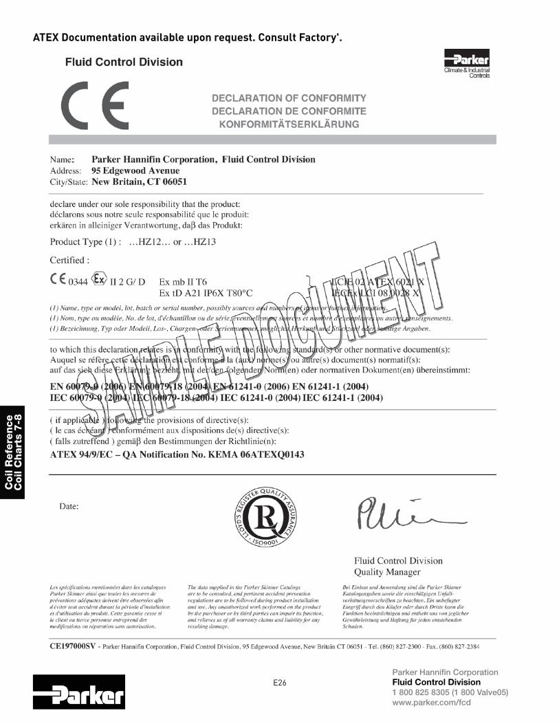
ATEX Documentation available upon request. Consult Factory'.
E27Parker Hannifin CorporationFluid Control Division
1 800 825 8305 (1 800 Valve05)www.parker.com/fcd
Coil R
efe
rence
Coil C
hart 9
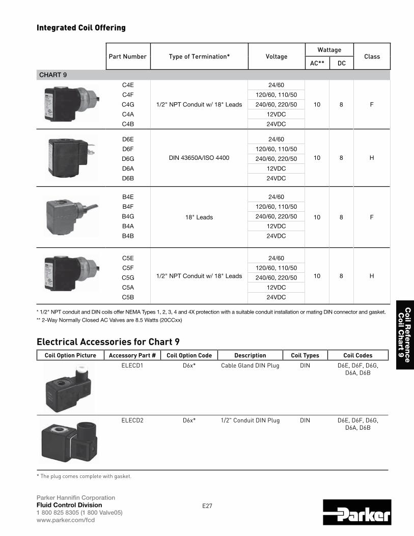
CHART 9
C4E
1/2" NPT Conduit w/ 18" Leads
24/60
10 8 F
C4F 120/60, 110/50
C4G 240/60, 220/50
C4A 12VDC
C4B 24VDC
D6E
DIN 43650A/ISO 4400
24/60
10 8 HD6F 120/60, 110/50
D6G 240/60, 220/50
D6A 12VDC
D6B 24VDC
B4E
18" Leads
24/60
10 8 F
B4F 120/60, 110/50
B4G 240/60, 220/50
B4A 12VDC
B4B 24VDC
C5E
1/2" NPT Conduit w/ 18" Leads
24/60
10 8 HC5F 120/60, 110/50
C5G 240/60, 220/50
C5A 12VDC
C5B 24VDC
* 1/2" NPT conduit and DIN coils offer NEMA Types 1, 2, 3, 4 and 4X protection with a suitable conduit installation or mating DIN connector and gasket.
** 2-Way Normally Closed AC Valves are 8.5 Watts (20CCxx)
Part Number Type of Termination* VoltageWattage
ClassAC** DC
Integrated Coil Offering
Electrical Accessories for Chart 9Coil Option Picture Accessory Part # Coil Option Code Description Coil Types Coil Codes
ELECD1 D6x* Cable Gland DIN Plug DIN D6E, D6F, D6G, D6A, D6B
ELECD2 D6x* 1/2" Conduit DIN Plug DIN D6E, D6F, D6G, D6A, D6B
* The plug comes complete with gasket.