Embed Size (px)
Citation preview
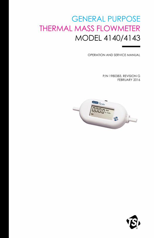
GENERAL PURPOSE
THERMAL MASS FLOWMETER
MODEL 4140/4143
OPERATION AND SERVICE MANUAL
P/N 1980383, REVISION G
FEBRUARY 2016
GENERAL PURPOSE
THERMAL MASS FLOWMETER
MODEL 4140/4143
OPERATION AND SERVICE MANUAL
P/N 1980383, REVISION G
FEBRUARY 2016
U.S. & INTERNATIONAL TSI Instruments Ltd. (UK)
Sales and Customer Service: Sales and Customer Service:
(800) 874-2811 / +1(651) 490-2811 +44 (0) 1494 459200
Fax: Fax:
+1(651) 490-3824 +44 (0) 1494 459700

i
Copyright TSI Incorporated / 2003-2016 / All rights reserved.
Address TSI Incorporated, 500 Cardigan Road, Shoreview, MN 55126 USA
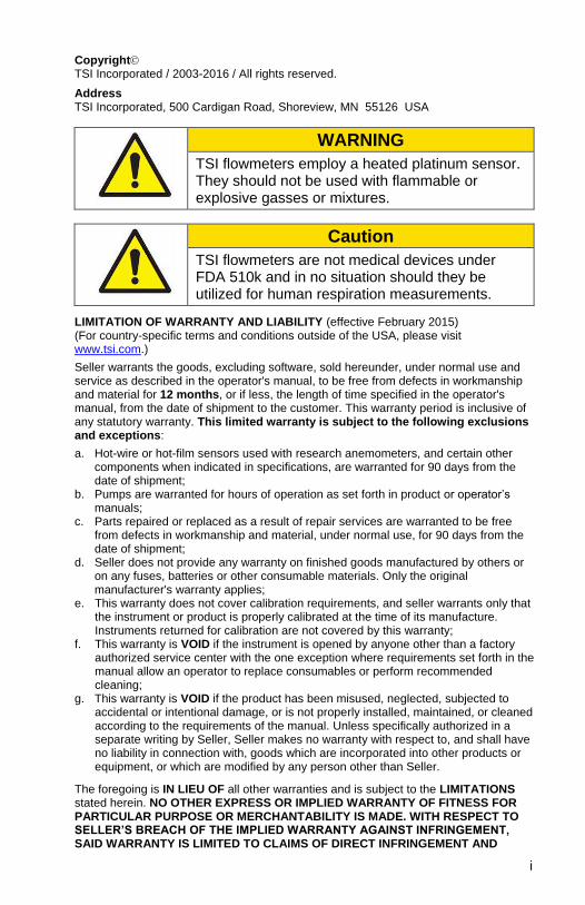
WARNING
TSI flowmeters employ a heated platinum sensor. They should not be used with flammable or explosive gasses or mixtures.
Caution
TSI flowmeters are not medical devices under FDA 510k and in no situation should they be utilized for human respiration measurements.
LIMITATION OF WARRANTY AND LIABILITY (effective February 2015) (For country-specific terms and conditions outside of the USA, please visit www.tsi.com.)
Seller warrants the goods, excluding software, sold hereunder, under normal use and service as described in the operator's manual, to be free from defects in workmanship and material for 12 months, or if less, the length of time specified in the operator's manual, from the date of shipment to the customer. This warranty period is inclusive of any statutory warranty. This limited warranty is subject to the following exclusions and exceptions:
a. Hot-wire or hot-film sensors used with research anemometers, and certain other components when indicated in specifications, are warranted for 90 days from the date of shipment;
b. Pumps are warranted for hours of operation as set forth in product or operator’s manuals;
c. Parts repaired or replaced as a result of repair services are warranted to be free from defects in workmanship and material, under normal use, for 90 days from the date of shipment;
d. Seller does not provide any warranty on finished goods manufactured by others or on any fuses, batteries or other consumable materials. Only the original manufacturer's warranty applies;
e. This warranty does not cover calibration requirements, and seller warrants only that the instrument or product is properly calibrated at the time of its manufacture. Instruments returned for calibration are not covered by this warranty;
f. This warranty is VOID if the instrument is opened by anyone other than a factory authorized service center with the one exception where requirements set forth in the manual allow an operator to replace consumables or perform recommended cleaning;
g. This warranty is VOID if the product has been misused, neglected, subjected to accidental or intentional damage, or is not properly installed, maintained, or cleaned according to the requirements of the manual. Unless specifically authorized in a separate writing by Seller, Seller makes no warranty with respect to, and shall have no liability in connection with, goods which are incorporated into other products or equipment, or which are modified by any person other than Seller.
The foregoing is IN LIEU OF all other warranties and is subject to the LIMITATIONS stated herein. NO OTHER EXPRESS OR IMPLIED WARRANTY OF FITNESS FOR PARTICULAR PURPOSE OR MERCHANTABILITY IS MADE. WITH RESPECT TO SELLER’S BREACH OF THE IMPLIED WARRANTY AGAINST INFRINGEMENT, SAID WARRANTY IS LIMITED TO CLAIMS OF DIRECT INFRINGEMENT AND
ii
EXCLUDES CLAIMS OF CONTRIBUTORY OR INDUCED INFRINGEMENTS. BUYER’S EXCLUSIVE REMEDY SHALL BE THE RETURN OF THE PURCHASE PRICE DISCOUNTED FOR REASONABLE WEAR AND TEAR OR AT SELLER’S OPTION REPLACEMENT OF THE GOODS WITH NON-INFRINGING GOODS.
TO THE EXTENT PERMITTED BY LAW, THE EXCLUSIVE REMEDY OF THE USER OR BUYER, AND THE LIMIT OF SELLER'S LIABILITY FOR ANY AND ALL LOSSES, INJURIES, OR DAMAGES CONCERNING THE GOODS (INCLUDING CLAIMS BASED ON CONTRACT, NEGLIGENCE, TORT, STRICT LIABILITY OR OTHERWISE) SHALL BE THE RETURN OF GOODS TO SELLER AND THE REFUND OF THE PURCHASE PRICE, OR, AT THE OPTION OF SELLER, THE REPAIR OR REPLACEMENT OF THE GOODS. IN THE CASE OF SOFTWARE, SELLER WILL REPAIR OR REPLACE DEFECTIVE SOFTWARE OR IF UNABLE TO DO SO, WILL REFUND THE PURCHASE PRICE OF THE SOFTWARE. IN NO EVENT SHALL SELLER BE LIABLE FOR LOST PROFITS, BUSINESS INTERRUPTION, OR ANY SPECIAL, INDIRECT, CONSEQUENTIAL OR INCIDENTAL DAMAGES. SELLER SHALL NOT BE RESPONSIBLE FOR INSTALLATION, DISMANTLING OR REINSTALLATION COSTS OR CHARGES. No Action, regardless of form, may be brought against Seller more than 12 months after a cause of action has accrued. The goods returned under warranty to Seller's factory shall be at Buyer's risk of loss, and will be returned, if at all, at Seller's risk of loss.
Buyer and all users are deemed to have accepted this LIMITATION OF WARRANTY AND LIABILITY, which contains the complete and exclusive limited warranty of Seller. This LIMITATION OF WARRANTY AND LIABILITY may not be amended, modified or its terms waived, except by writing signed by an Officer of Seller.
Service Policy Knowing that inoperative or defective instruments are as detrimental to TSI attention to any problems. If any malfunction is discovered, please contact your nearest sales office or representative, or call TSI's Customer Service department at (800) 874-2811 (USA) or (001 651) 490-2811 (International) or visit www.tsi.com.
iii
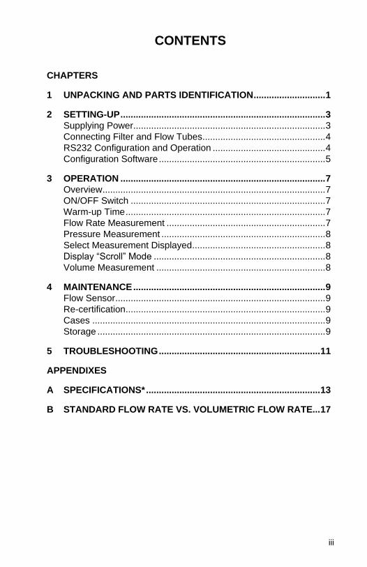
CONTENTS
CHAPTERS
1 UNPACKING AND PARTS IDENTIFICATION ............................ 1
2 SETTING-UP ................................................................................ 3 Supplying Power ........................................................................... 3
Connecting Filter and Flow Tubes ................................................ 4 RS232 Configuration and Operation ............................................ 4 Configuration Software ................................................................. 5
3 OPERATION ................................................................................ 7
Overview ....................................................................................... 7 ON/OFF Switch ............................................................................ 7 Warm-up Time .............................................................................. 7 Flow Rate Measurement .............................................................. 7 Pressure Measurement ................................................................ 8 Select Measurement Displayed .................................................... 8 Display “Scroll” Mode ................................................................... 8 Volume Measurement .................................................................. 8
4 MAINTENANCE ........................................................................... 9
Flow Sensor .................................................................................. 9 Re-certification .............................................................................. 9 Cases ........................................................................................... 9 Storage ......................................................................................... 9
5 TROUBLESHOOTING ............................................................... 11
APPENDIXES
A SPECIFICATIONS* .................................................................... 13
B STANDARD FLOW RATE VS. VOLUMETRIC FLOW RATE... 17

iv
(This page intentionally left blank)
1
Chapter 1
Unpacking and Parts Identification
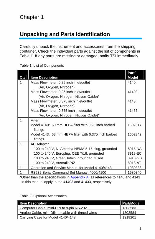
Carefully unpack the instrument and accessories from the shipping
container. Check the individual parts against the list of components in
Table 1. If any parts are missing or damaged, notify TSI immediately.
Table 1. List of Components
Qty Item Description
Part/
Model
1 Mass Flowmeter, 0.25 inch inlet/outlet
(Air, Oxygen, Nitrogen)
Mass Flowmeter, 0.25 inch inlet/outlet
(Air, Oxygen, Nitrogen, Nitrous Oxide)*
Mass Flowmeter, 0.375 inch inlet/outlet
(Air, Oxygen, Nitrogen)
Mass Flowmeter, 0.375 inch inlet/outlet
(Air, Oxygen, Nitrogen, Nitrous Oxide)*
4140
41403
4143
41433
1 Filter
Model 4140: 60 mm ULPA filter with 0.25 inch barbed
fittings
Model 4143: 63 mm HEPA filter with 0.375 inch barbed
fittings
1602317
1602342
1 AC Adapter
100 to 240 V, N. America NEMA 5-15 plug, grounded
100 to 240 V, Europlug, CEE 7/16, grounded
100 to 240 V, Great Britain, grounded, fused
100 to 240 V, Australia/NZ
8918-NA
8918-EC
8918-GB
8918-AT
1 Operation and Service Manual for Model 4140/4143 1980383
1 RS232 Serial Command Set Manual, 4000/4100 1980340
*Other than the specifications in Appendix A, all references to 4140 and 4143
in this manual apply to the 41403 and 41433, respectively.
Table 2. Optional Accessories
Item Description Part/Model
Computer Cable, mini-DIN to 9-pin RS-232 1303583
Analog Cable, mini-DIN to cable with tinned wires 1303584
Carrying Case for Model 4140/4143 1319201
Chapter 1 2
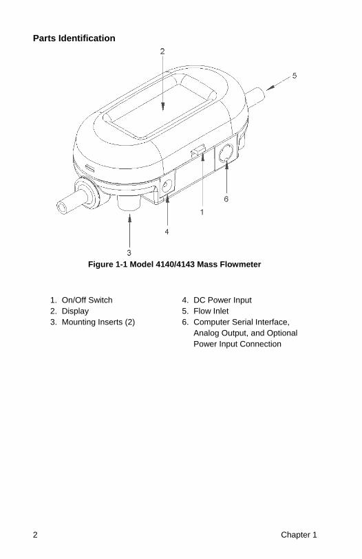
Parts Identification
Figure 1-1 Model 4140/4143 Mass Flowmeter
1. On/Off Switch 4. DC Power Input
2. Display 5. Flow Inlet
3. Mounting Inserts (2) 6. Computer Serial Interface,
Analog Output, and Optional
Power Input Connection
3
Chapter 2
Setting-Up
Supplying Power
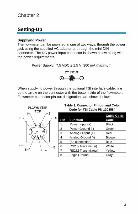
The flowmeter can be powered in one of two ways: through the power
jack using the supplied AC adapter or through the mini-DIN
connector. The DC power input connector is shown below along with
the power requirements.
Power Supply: 7.5 VDC ± 1.5 V, 300 mA maximum
When supplying power through the optional TSI interface cable, line
up the arrow on the connector with the bottom side of the flowmeter.
Flowmeter connector pin-out designations are shown below.
Table 3. Connector Pin-out and Color
Code for TSI Cable PN 1303584
Pin Function
Cable Color
Code
1 Power Input (+) Black
2 Power Ground (-) Green
3 Analog Output (+) Red
4 Analog Ground (-) Brown
5 (no connection) Blue
6 RS232 Receive (in) White
7 RS232 Transmit (out) Yellow
8 Logic Ground Gray
4 Chapter 2
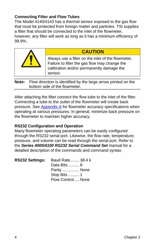
Connecting Filter and Flow Tubes
The Model 4140/4143 has a thermal sensor exposed to the gas flow
that must be protected from foreign matter and particles. TSI supplies
a filter that should be connected to the inlet of the flowmeter,
however, any filter will work as long as it has a minimum efficiency of
99.9%.
CAUTION
Always use a filter on the inlet of the flowmeter.
Failure to filter the gas flow may change the
calibration and/or permanently damage the
sensor.
Note: Flow direction is identified by the large arrow printed on the bottom side of the flowmeter.
After attaching the filter connect the flow tube to the inlet of the filter.
Connecting a tube to the outlet of the flowmeter will create back
pressure. See Appendix A for flowmeter accuracy specifications when
operating at various pressures. In general, minimize back pressure on
the flowmeter to maintain higher accuracy.
RS232 Configuration and Operation
Many flowmeter operating parameters can be easily configured
through the RS232 serial port. Likewise, the flow rate, temperature,
pressure, and volume can be read through the serial port. Refer to
the Series 4000/4100 RS232 Serial Command Set manual for a
detailed description of the commands and command syntax.
RS232 Settings: Baud Rate ........ 38.4 k
Data Bits .......... 8
Parity ................ None
Stop Bits .......... 1
Flow Control ..... None
Setting Up 5
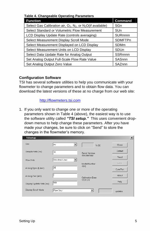
Table 4. Changeable Operating Parameters
Function Command
Select Gas Calibration air, O2, N2, or N2O(if available) SGn
Select Standard or Volumetric Flow Measurement SUn
LCD Display Update Rate (controls averaging) SURnnnn
Select Measurement Display Scroll Mode SDMFTPn
Select Measurement Displayed on LCD Display SDMm
Select Measurement Units on LCD Display SDUn
Select Data Update Rate for Analog Output SSRnnnn
Set Analog Output Full-Scale Flow Rate Value SASnnn
Set Analog Output Zero Value SAZnnn
Configuration Software
TSI has several software utilities to help you communicate with your
flowmeter to change parameters and to obtain flow data. You can
download the latest versions of these at no charge from our web site:
http://flowmeters.tsi.com
1. If you only want to change one or more of the operating
parameters shown in Table 4 (above), the easiest way is to use
the software utility called “TSI setup.” This uses convenient drop-
down menus to help change these parameters. After you have
made your changes, be sure to click on “Send” to store the
changes in the flowmeter’s memory.
6 Chapter 2
2. If you want to communicate directly with the flowmeter using the
basic RS232 commands shown in the Serial Command Set
Manual, you can use a terminal program. HyperTerminal is a
common terminal program that is included with most versions of
the Microsoft operating system. Setting up HyperTerminal to
communicate with your flowmeter can sometimes be confusing.
You can download a document from our web site that helps you
configure HyperTerminal. Download the document called “Using
HyperTerminal to communicate with TSI Flowmeters.”
3. If you plan to develop a more sophisticated program for data
collection and control using LabVIEW, you can download a
demonstration program called “Real-time Demo Program” and
the source code “Source Code for Real-time Demo Program.”
This program is intended to be a basic demonstration program and
not a practical laboratory tool. It does, however, have a convenient
implementation of the VOLUME measurement function that can be
useful for basic tests.
7
Chapter 3
Operation
CAUTION
TSI flowmeters are not medical devices under
FDA 510k and in no situation should they be
utilized for human respiration measurements.
Overview
The Model 4140/4143 Flowmeter measures mass flow rate,
temperature and absolute pressure of the gas inside the flow tube. All
measurements made by the Models 4140/4143 are NIST traceable.
ON/OFF Switch
Slide the switch to the ON position. The power switch is marked in the
international symbols '|' for on and 'O' for off.
Warm-up Time
The flowmeter will provide readings immediately upon power-up.
Recommended warm-up time of the flowmeter is 5 minutes.
Flow Rate Measurement
Flow rate data can be obtained from the Model 4140/4143 through
the LCD display, RS232 serial port, or the linearized analog output.
The analog output is a 0 to 10 volt DC linear signal representing 0 to
20 Std L/min. The analog output scaling is user selectable. Refer to
the Series 4000/4100 RS232 Serial Command Set manual for
instructions on how to obtain flow data through the serial port.
Gas calibrations (air, 100% O2, 100% N2 or 100% N2O) can be
selected through the RS232 serial port. Refer to the Series
4000/4100 RS232 Serial Command Set manual. The LCD display
will indicate the calibration being utilized: air, O2, N2, or N2O.
Flow can be displayed in units of standard liters per minute
(Std L/min*) or in volumetric units of liters per minute (L/min). Refer to
Appendix B for a description of the two measurements. Selecting
between the two measurements is accomplished through the serial
*TSI instruments defines standard conditions as 21.1°C (70° F) and 101.3 kPa (14.7
psia, 1 bar).
8 Chapter 3
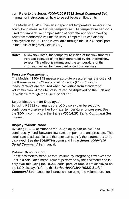
port. Refer to the Series 4000/4100 RS232 Serial Command Set
manual for instructions on how to select between flow units.
The Model 4140/4143 has an independent temperature sensor in the
flow tube to measure the gas temperature. The temperature sensor is
used for temperature compensation of flow rate and for converting
flow from standard to volumetric units. Temperature can also be
displayed on the LCD and is available through the RS232 serial port
in the units of degrees Celsius (°C).
Note: At low flow rates, the temperature inside of the flow tube will increase because of the heat generated by the thermal flow sensor. This effect is normal and the temperature of the incoming gas will be measured once flow resumes.
Pressure Measurement
The Models 4140/4143 measure absolute pressure near the outlet of
the flowmeter in the SI units of kilo-Pascals (kPa). Pressure
measurements are required when converting from standard to
volumetric flow. Absolute pressure can be displayed on the LCD and
is available through the RS232 serial port.
Select Measurement Displayed
By using RS232 commands the LCD display can be set up to
continuously display either flow rate, temperature, or pressure. See
the SDMm command in the Series 4000/4100 Serial Command Set
manual.
Display “Scroll” Mode
By using RS232 commands the LCD display can be set up to
continuously scroll between flow rate, temperature, and pressure. The
scroll rate is adjustable and the user can specify the parameters to be
displayed. See the SDMFTPn command in the Series 4000/4100
Serial Command Set manual.
Volume Measurement
These flowmeters measure total volume by integrating flow over time.
This is a calculated measurement performed by the flowmeter and is
only available using the RS232 serial port. Volume is not displayed on
the LCD display. Refer to the Series 4000/4100 RS232 Serial
Command Set manual for instructions on using the volume function.
9
Chapter 4
Maintenance
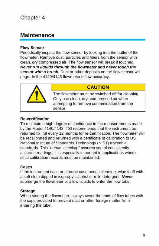
Flow Sensor
Periodically inspect the flow sensor by looking into the outlet of the
flowmeter. Remove dust, particles and fibers from the sensor with
clean, dry compressed air. The flow sensor will break if touched.
Never run liquids through the flowmeter and never touch the
sensor with a brush. Dust or other deposits on the flow sensor will
degrade the 4140/4143 flowmeter’s flow accuracy.
CAUTION
The flowmeter must be switched off for cleaning.
Only use clean, dry, compressed air when
attempting to remove contamination from the
sensor.
Re-certification
To maintain a high degree of confidence in the measurements made
by the Model 4140/4143, TSI recommends that the instrument be
returned to TSI every 12 months for re-certification. The flowmeter will
be recalibrated and returned with a certificate of calibration to US
National Institute of Standards Technology (NIST) traceable
standards. This “annual checkup” assures you of consistently
accurate readings; it is especially important in applications where
strict calibration records must be maintained.
Cases
If the instrument case or storage case needs cleaning, wipe it off with
a soft cloth dipped in isopropyl alcohol or mild detergent. Never
submerge the flowmeter or allow liquids to enter the flow tube.
Storage
When storing the flowmeter, always cover the ends of flow tubes with
the caps provided to prevent dust or other foreign matter from
entering the tube.

10 Chapter 4
(This page intentionally left blank)
11
Chapter 5
Troubleshooting
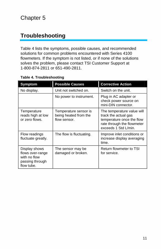
Table 4 lists the symptoms, possible causes, and recommended
solutions for common problems encountered with Series 4100
flowmeters. If the symptom is not listed, or if none of the solutions
solves the problem, please contact TSI Customer Support at
1-800-874-2811 or 651-490-2811.
Table 4. Troubleshooting
Symptom Possible Causes Corrective Action
No display. Unit not switched on. Switch on the unit.
No power to instrument. Plug in AC adapter or check power source on mini-DIN connector.
Temperature reads high at low or zero flows.
Temperature sensor is being heated from the flow sensor.
The temperature value will track the actual gas temperature once the flow rate through the flowmeter exceeds 1 Std L/min.
Flow readings fluctuate greatly.
The flow is fluctuating. Improve inlet conditions or increase display averaging time.
Display shows flows over-range with no flow passing through flow tube.
The sensor may be damaged or broken.
Return flowmeter to TSI for service.

12 Chapter 5
(This page intentionally left blank)
13
Appendix A
Specifications*
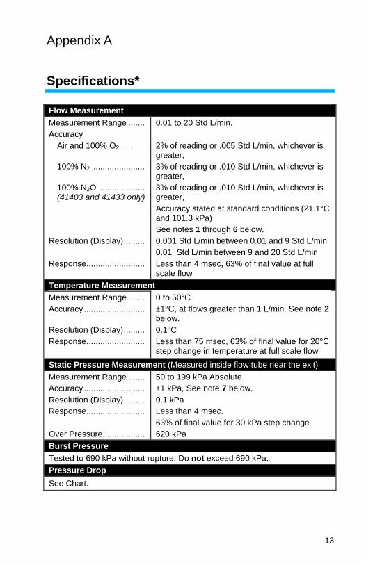
Flow Measurement
Measurement Range .......
Accuracy
Air and 100% O2 ................
100% N2 ......................
100% N2O ................... (41403 and 41433 only)
Resolution (Display) .........
Response .........................
0.01 to 20 Std L/min.
2% of reading or .005 Std L/min, whichever is greater,
3% of reading or .010 Std L/min, whichever is greater,
3% of reading or .010 Std L/min, whichever is greater,
Accuracy stated at standard conditions (21.1°C and 101.3 kPa)
See notes 1 through 6 below.
0.001 Std L/min between 0.01 and 9 Std L/min
0.01 Std L/min between 9 and 20 Std L/min
Less than 4 msec, 63% of final value at full scale flow
Temperature Measurement
Measurement Range .......
Accuracy ..........................
Resolution (Display) .........
Response .........................
0 to 50°C
±1°C, at flows greater than 1 L/min. See note 2 below.
0.1°C
Less than 75 msec, 63% of final value for 20°C step change in temperature at full scale flow
Static Pressure Measurement (Measured inside flow tube near the exit)
Measurement Range .......
Accuracy ..........................
Resolution (Display) .........
Response .........................
Over Pressure ..................
50 to 199 kPa Absolute
±1 kPa, See note 7 below.
0.1 kPa
Less than 4 msec.
63% of final value for 30 kPa step change
620 kPa
Burst Pressure
Tested to 690 kPa without rupture. Do not exceed 690 kPa.
Pressure Drop
See Chart.
14 Appendix A
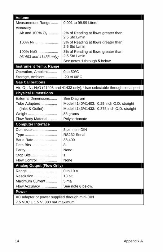
Volume
Measurement Range .......
Accuracy
Air and 100% O2 .........
100% N2 ......................
100% N2O ...................
(41403 and 41433 only)
0.001 to 99.99 Liters
2% of Reading at flows greater than 2.5 Std L/min
3% of Reading at flows greater than 2.5 Std L/min
3% of Reading at flows greater than 2.5 Std L/min
See notes 1 through 5 below.
Instrument Temp. Range
Operation, Ambient .........
Storage, Ambient ............
0 to 50°C
-20 to 60°C
Gas Calibrations
Air, O2, N2, N2O (41403 and 41433 only), User selectable through serial port
Physical Dimensions
External Dimensions .......
Tube Adapters ................
(Inlet & Outlet)
Weight ............................
Flow Body Material .........
See Diagram
Model 4140/41403: 0.25 inch O.D. straight
Model 4143/41433: 0.375 inch O.D. straight
86 grams
Polycarbonate
Computer Interface
Connector .......................
Type ...............................
Baud Rate ......................
Data Bits .........................
Parity ..............................
Stop Bits .........................
Flow Control ...................
8 pin mini-DIN
RS232 Serial
38,400
8
None
1
None
Analog Output (Flow Only)
Range .............................
Resolution ......................
Maximum Current ...........
Flow Accuracy ................
0 to 10 V
13 bit
5 ma
See note 6 below.
Power
AC adapter or power supplied through mini-DIN
7.5 VDC ± 1.5 V, 300 mA maximum
Specifications 15
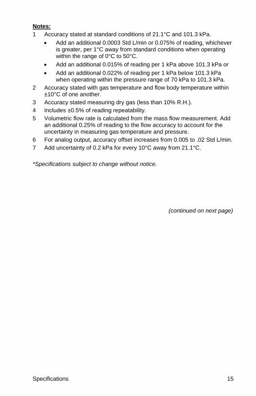
Notes:
1 Accuracy stated at standard conditions of 21.1°C and 101.3 kPa.
Add an additional 0.0003 Std L/min or 0.075% of reading, whichever is greater, per 1°C away from standard conditions when operating within the range of 0°C to 50°C.
Add an additional 0.015% of reading per 1 kPa above 101.3 kPa or
Add an additional 0.022% of reading per 1 kPa below 101.3 kPa when operating within the pressure range of 70 kPa to 101.3 kPa.
2 Accuracy stated with gas temperature and flow body temperature within ±10°C of one another.
3 Accuracy stated measuring dry gas (less than 10% R.H.).
4 Includes ±0.5% of reading repeatability.
5 Volumetric flow rate is calculated from the mass flow measurement. Add an additional 0.25% of reading to the flow accuracy to account for the uncertainty in measuring gas temperature and pressure.
6 For analog output, accuracy offset increases from 0.005 to .02 Std L/min.
7 Add uncertainty of 0.2 kPa for every 10°C away from 21.1°C.
*Specifications subject to change without notice.
(continued on next page)
16 Appendix A
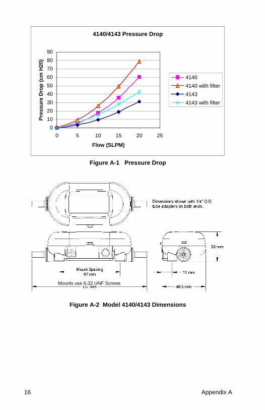
4140/4143 Pressure Drop
0
10
20
30
40
50
60
70
80
90
0 5 10 15 20 25
Flow (SLPM)
Pre
ssu
re D
rop
(cm
H20)
4140
4140 with filter
4143
4143 with filter
Figure A-1 Pressure Drop
Figure A-2 Model 4140/4143 Dimensions
Mounts use 6-32 UNF Screws
17
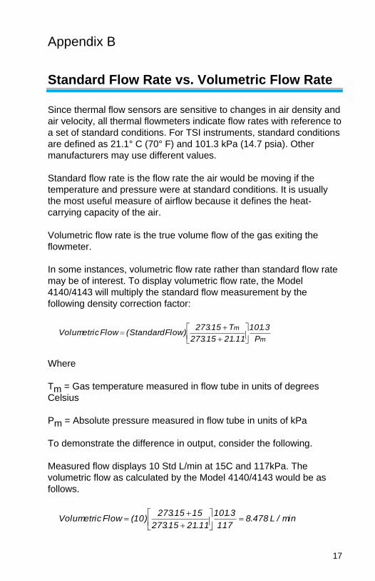
Appendix B
Standard Flow Rate vs. Volumetric Flow Rate
Since thermal flow sensors are sensitive to changes in air density and
air velocity, all thermal flowmeters indicate flow rates with reference to
a set of standard conditions. For TSI instruments, standard conditions
are defined as 21.1° C (70° F) and 101.3 kPa (14.7 psia). Other
manufacturers may use different values.
Standard flow rate is the flow rate the air would be moving if the
temperature and pressure were at standard conditions. It is usually
the most useful measure of airflow because it defines the heat-
carrying capacity of the air.
Volumetric flow rate is the true volume flow of the gas exiting the
flowmeter.
In some instances, volumetric flow rate rather than standard flow rate
may be of interest. To display volumetric flow rate, the Model
4140/4143 will multiply the standard flow measurement by the
following density correction factor:
m
m
P
3.101
11.2115.273
T15.273)FlowStandard(FlowVolumetric
Where
Tm = Gas temperature measured in flow tube in units of degrees
Celsius
Pm = Absolute pressure measured in flow tube in units of kPa
To demonstrate the difference in output, consider the following.
Measured flow displays 10 Std L/min at 15C and 117kPa. The
volumetric flow as calculated by the Model 4140/4143 would be as
follows.
min/L478.8117
3.101
11.2115.273
1515.273)10(FlowVolumetric

TSI Incorporated – Visit our website www.tsi.com for more information. USA Tel: +1 800 874 2811 UK Tel: +44 149 4 459200 France Tel: +33 1 41 19 21 99 Germany Tel: +49 241 523030
India Tel: +91 80 67877200 China Tel: +86 10 8219 7688 Singapore Tel: +65 6595 6388
P/N 1980383 Rev G Copyright © 2016 by TSI Incorporated Printed in U.S.A.
*1980383*