Embed Size (px)
Citation preview
The GENERAL RADIO
EXPERIMENTER VOL. IX. No. 8 JANUARY, 1935
ELECTRICAL COMMUNICATIONS TECl-I N IQUE ALLIED t=IELDS AND ITS APPLICATIONS IN
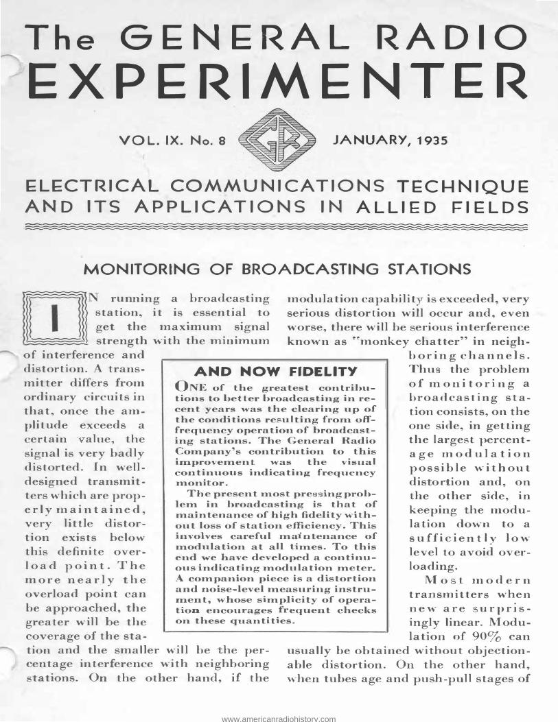
MONITORING OF BROADCASTING STATIONS
DJ running a broadcasting ' station., it is
. essentia
_I to
get the maximum signal strength with ·t e minimum
of interference and
modulation capabilit is exceeded, very serious distortion. will occur and, even worse, there will be serious interference known as ��monkey chatter" in neigh
distortion. A transmi-tter differs from ordinary circuits in that, once the amplitude exceeds a
ertain alue, the signal is very badly distorted. In welldesign.ed tran.sm·tters which are prope r ly ma i n t a i n e d , very little distortion exists belff\V this definite over-1 o a d p o i n t . Th e m o r e ne a r l y t h e overload point can be approached, the greater will be the coverage of the sta
AND NOW FIDELITY ONE of the greatest contributions to better broadcasting in recent years was the clearing up of the conditions re ul ting from offfrequency operation of broadcasting stations. The General Radio Company's contribution to this improvement was the visual continuous indicating frequency moni oI·.
The present :most pre ing problem in broadcasting is that of maintenance of high fidelity without loss of station efficiency. This involves careful ma "n.tenance of modulation at all times. To this end we have developed a continuous indicating modulation meterA companion piece is a distortion and :noise-level measuring instrument, whose simplicity of operatio encourages f equent checks on these quantities.
bo r i n g c h a n n els . Thu the problem of m o n i t o r i n g a b roa dcasting sta·tion consists, on the one side, in getting the larges · t percenta g e mo d ul a t i o n p o s s i ble wi thout dis or ion and, on the other side, in keeping the modulation down to a s uffi c i e n t ly low level to avoid over
loading. M o t 1no d e r n
transmitters when n e w a r e u r p r1s ingly linear. Modulation. of 90% can
tion and the smaller will be he percentage interference with neighboring
usually be obtained withou t obje tionable distortion. On the other hand, when tubes age and push-pull stages of tations. On. the other hand, if the
www.americanradiohistory.com

2 THE GENERAL RADIO EXPERIMENTER
amplification b come unbalanced, the tran mi tter is likely to become very badly non-linear.
t present, it is the practice w·th most stations to monitor the programs at the tudio, maintaining a certain input level to the line leading to the remote tra mitter, the level being determined by a power-level indi ator. Another power-le el indicator is used at the transmitter to make certain that the transmission line has not changed
ufficiently to make serious overloading po sibl . E� cept under abnormal conditions, no control is permitted at the transmitter itself. In the be t pre ent practice the input power level permi ible for a given type of program is d t rmined by te t on the transmitter whi h correlate percentage modulation and distortion with "nput level.
Thi whole system is very badly at faul t in everal small bu t important: detail . In the firs t p1ace the volume-level indicators are not at all instantaneous in their ac tion an the overmodula tion peak which are re ponsible for all of the trouble are seldom of sufficient durat·on o reg· ter on the monitoring meter . In addition to the fact that the me ter are not in tantaneou , it so happens that most of tho e at pre ent in u e are subject to resonance troubles
o that the fail to give a proper idea of the mean pow r in a yllable as well as not following peak . A pulse of given intensity may transien tly gi e an indication 3 or 4 decibels hig er than the true value. Such a condition an result in radi alJy wrong monitoring; a change of 3 de ibels in adju tment would re-
ult in halving efficiency. T e full significance of these meter faults has not been generally realized.
There is a further difficulty in that
at present the program. is monitored at the input to the transmitter ra ther than at the ou-tput. This means that changes in the gain of any of the audiofrequency amplifiers or in the modula -tor efficiency are not taken into account except by comparatively infrequent periodic checks. This practice has resulted from the lack of equipment designed for continuous monitoring.
Previous equipment was fairl sati -factory so far as it went but did not lend itself readily to rapid e perimental checks, and a a result it was paringly used by the operating taff , tests being made every week or so. For this reason it was necessary to provide too large a safety factor and to u e an unnecessarily low peak modulation to be sure of satisfactory transmi ion. Conversely, stations which have :not been allowing such afety factor ha e had unne e -
arily high di tor tion. With these condi tions in mind, the
General Radio Company has designed a group of instruments to reduce the monitoring of broadcasting station to a very imple procedure which can be carried on continuou ly and accurately.
The TYPE 731-A Modulation Monitor i designed so that it can be coupled directly to the radio-frequency output of the transmitter. An automatic bia -ing arrangement used in conjunction with a thyratron flashes a light whenever the modulation instantaneous} exceeds the value which is considered permi sible with the part·cular transmitter. In addition, meters are provided to indicate carrier hift and percentage modulation.. The per cent meter is direct reading on positive or negative peaks and is of the rapid movement type recen tly developed. While not instantaneous, it is free from resonance effect
www.americanradiohistory.com
'·
JANUARY, 1935-VOL. IX-No. 8 3
and follows a sign.al much more faithfully and rapidly than the previous instruments.
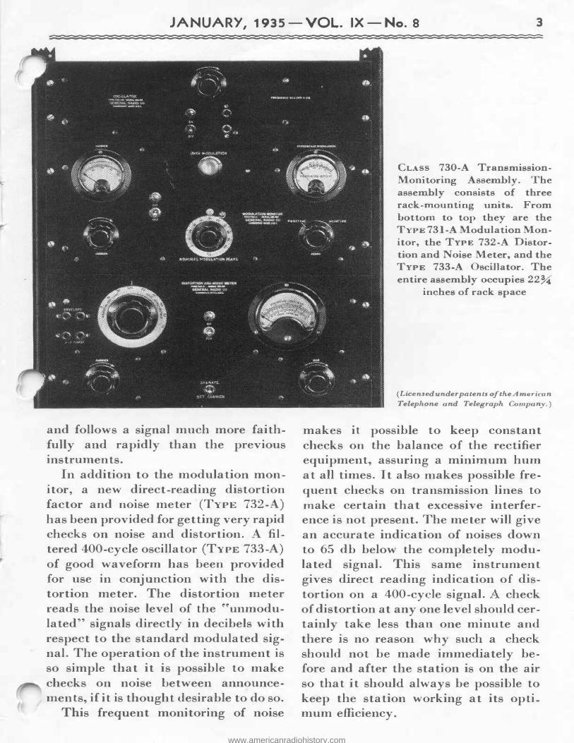
In addition to the modulation monitor, a new direct-reading distortion factor and noise meter (TYPE 732-A) has been provided for getting very rapid checks on noise and distortion. A :filtered 400-cycle oscillator (TYPE 733-A) of good waveform has been provided for use in con.junction. with the distortion. meter. The distortion. meter reads the noise level of the ''unmodulated" signals directly in decibels with respect to the standard modulated signal. The operation of the instrument is so simple that it is possible to make checks on noise between announcements, if it is thought desirable to do so.
This frequent monitoring of noise
CLASS 730-A TransmissionMonitoring Assembly. The assembly consists of three rack-mounting units. From bottom to top they are the TYPE 731-A Modulation Monitor, the TYPE 732-A Distortion and Noise Meter, and the TYPE 733-A Oscillator. The entire assembly occupies 22 %
inches of rack space
(Licensed under patents of the A me i-ican
Telephone and Telegraph Company.)
makes it possible to keep constant checks on the balance of the rectifier equipment, assuring a minimum hum at all times. It al o makes possible frequent checks on transmission. lines to make certain that excessive interference is not present. The meter will give an accurate indication of noises down to 65 db below the completely modulated signal. This same instrument gives direct reading indication of distortion on a 400-cycle signal. check of distortion at any one level should certainly take less than one minute and there is no reason why such a check should not be made immediately before and after the station is on the air so that it should always be possible to keep the station working at its optimum efficiency.
www.americanradiohistory.com
4 THE GENERAL RADIO EXPERIMENTER
A technical discu ion of all of the e in trument will be given in ne t month' issue of the PERIME TER. It is our belief that thi group of in.stru-
The CL 730- Transmi sion-Monitoring embly was designed by L. B. rguimbau. We er fortunate in ha ing the lo o-operatio of the engin ers of the Columbia Broad asting y t m in th development and testing of the apparatu .
E ery effort ha been made to design t e equipment o m t the a tual ondition of present installation and m thod of operation. The monitoring assem bly consists of three unit : odulation mete1· with o er-modulation. indicator (TYP 731- ) , di tortion. and noi e m ter (TYPE 732-A), 400- ycle oscilJator (TYPE 733-A). The equipment i capable f m asuring:
1. Per entage m d ulation on b th po itive and n gative peak .
2. Program monitoring with highspeed volume indica or meter.
3. Carrier hift upon the application of modulation.
. Carrier n.oi e and hum level.
S. Combined audi -fr quen har-monic di tortion of modulation envelope.
6. Modulation peak exceeding a predetermined, de ired degree of modulation (i . . ov r-m dulation indicator).
7. Combined audi -frequency harmonic distortion present in sp echinput amplifier and oth r station equipme t.
8. oi e and hum le el of audio amplifiers and other ta ti on equip-
men.ts will prove a very definite econ.om to broad a ting ta tions in enabling them to operate at the highe t po -
ihle level ons1 t nt with fidelity. -L. B. ARG IMBA
m nt, in luding wire Ii es to remote pickup points and to transmitter.
ith the addition of a variabl -frequen y audio o illator it i al o po -sible to measure:
9. Transmitter audio-frequen y response.
10. Audio amplifier and equipm nt frequency re pon
11. ire line frequen respon e.
o criti al adjustments or balances are required. The quantities measured are read directly from the instrument and no calculation are involved. In the cour e of operating tests the equipment has been u d to mea ure the chara teri tics of radio transmitters ranging from SO-watt portable remote pick p equipment to SO-kilowatt broadcast transmitters, as well a highfrequency transmitters operating at frequencies up to lS megacycle . Checks on. audio equipment have been mad on everything from portable field amplifier to program amplifiers and publi -address equipment.
It as been found po sible t make complete runs on a transmitter determining positi e and negative modulation peaks, per cent d i tortion, hum and noise level throughout the range of audio in.put of the tran mitter in le s
than ten minute . The entire monitoring assembly,
CL 730-A , i price.cl, at $462.00 (Code ord, E ILE). Pelivery will tart about February 28.
www.americanradiohistory.com
JANUARY, 1935-VOL. IX-No. 8 5
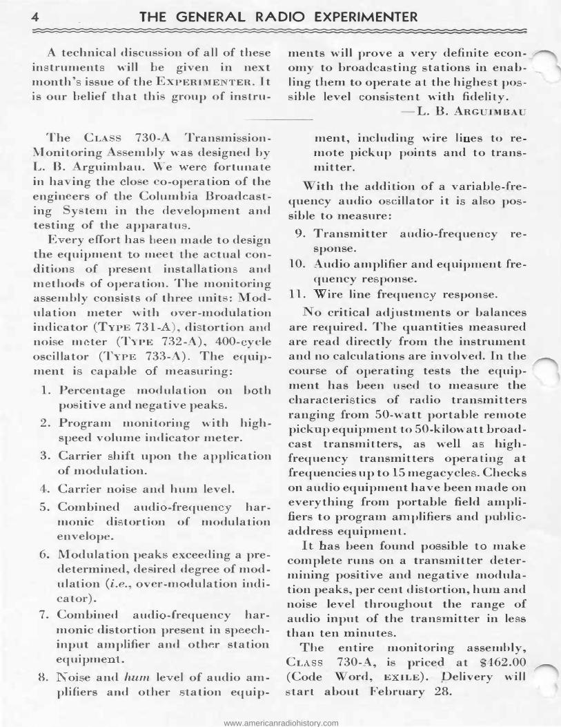
VARIAC APPLICATIONS IN PHOTOGRAPHY
PHOTOGRAPHY enthu ·a t have been finding a variety of applications for
the Variac auto-transformer d ribed in previous issues of the E ER ME TER.
This unit, which combines the ea e of control of a rheo tat with the high efficiency of a transformer, is being substituted for resistance controls in all of the photographic processe where control of light inten ity is required. Heretofore full advantage has not been taken of the possibilities of light control at the source of illumination a the equipment generally available has a number of limitations.
PHOTOFLOOD LAMPS Photofiood Lamps are being used by
thousands of photographers, professional and amateur. The life of the
o. l PhotofloodLamp is approximately two hours when operated on a 115-
volt circuit. During the major portion of its life, however, the lamps could be operated at reduced voltage, while arranging subjects, getting correct light angle , focusing, and all the other operations preliminary to actual e posure. The Variac makes it po ible to reduce
the voltage on the Photofl.ood Lamp to any desired value, and then to ��fl.ash" the lamp at norm.al voltage during ·the comparatively brief exposure period, thereby prolonging the life of the lamps greatly.
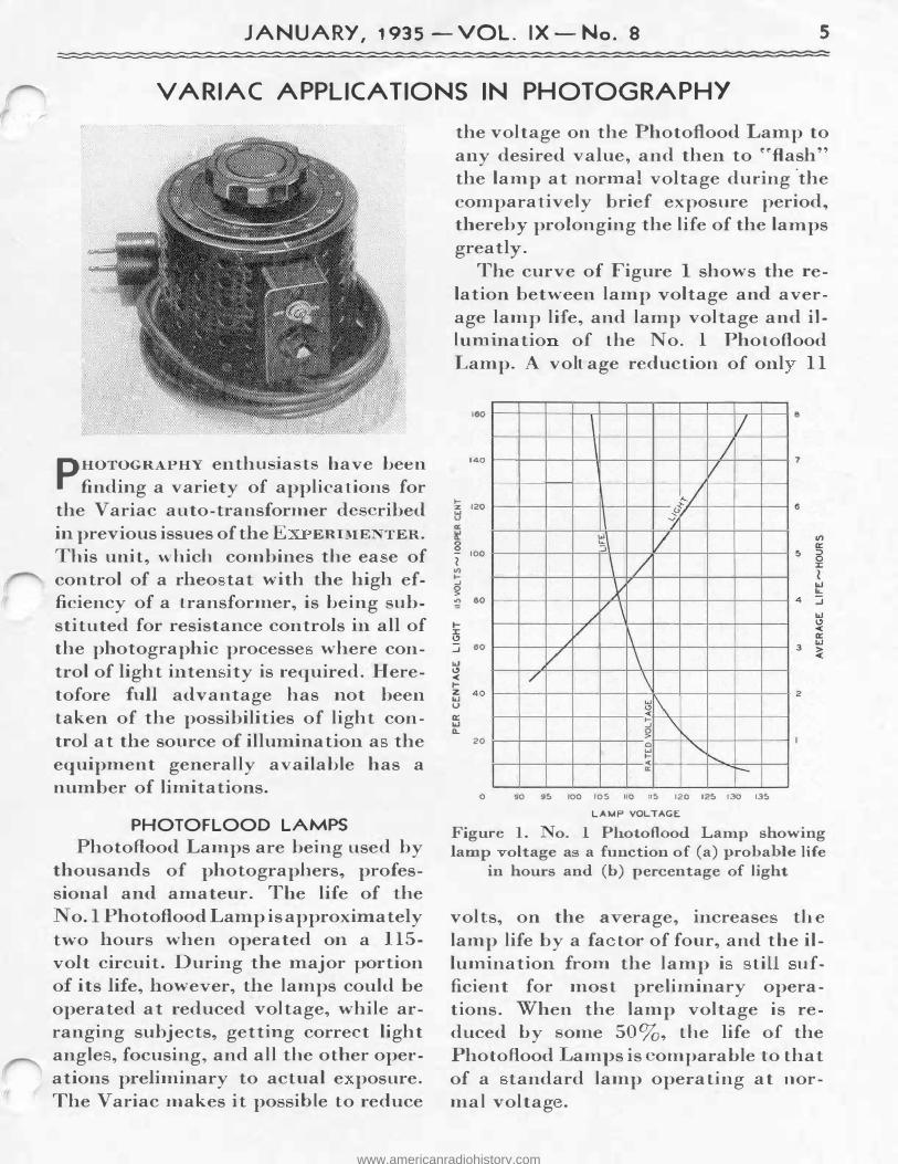
The curve of Figure 1 shows the relation between lamp voltage and average lamp life, and lamp voltage and illuminatio of the No. 1 Photoflood Lamp. A volt age reduction of onl 11
160 l I 8
140 / /
7
.... 120 z
w u a:
,_/ \
,"� /
It 8
100 I
II) .... _, g � 80
I-:r 0 ..J 60
w 0 < I-
�\ / \ / y
/ /\ // \
/ \ / \ z 40 w
u 0:: w a..
20
�� ....
'\!\.. _, 0 > 0 "" w .... ........_ < "' -
0 90 95 100 105 110 115 120 125 130 135
LAMP VOLTAGE
Figure 1. o. 1 Photoflood Lamp showing amp oltage a a function of (a) probable life
in hours and (b) percentage of light
volts, on the a er age, increase the lamp life by a fa tor of four, and the illumination from the lamp i ti ufficient for most preliminary operations. When the lamp voltage is reduced by ome 50%, the life of the Photoflood amps is �omparable to that of a tandard lamp operating at normal voltag .
www.americanradiohistory.com
6 THE GENERAL RADIO EXPERIMENTER
Some photographers are op rating Photoflood Lamps in groups of two, connecting them in series to secure half normal voltage during the preliminary adjustments, and in parallel for full illun1ination during the time of exposure. t half voltage the illumination is so low, comparati ely, that it is diffi ult to predict the re ult when the lamps are ope1·ated at normal voltage. The V ariac permit etti g the oltage on the lamp at any alue.
PROJECTION PRINTERS Photoflood Lamp are being used in
proje tion print r o that enlargements may be made on chloride or chloro-bromide contact paper. Some control of the brilliancy of the light is essential as the heat generated b the Photoflood Lamp is sufficient, in many cases, to cau e the negative to buckle before an exposure may be made. If used over prolonged periods at standard voltage, the Photoflood Lamp may damage the enlarging system, the reflector, or condensing lens, or the projection lens.
The V ariac allows continuous adjustment of the brilliance of the lamp, to reduce it during the time the negative is being adjusted and masked, the picture ''framed," and the paper adjusted. It also permits operating the Photoflood Lamps at reduced voltages when bromide papers are being enlarged upon.
In enlarging machines using standard electric lights, the several models of the V ariac giving output voltages higher than line voltage are very useful in that the standard lamp may be flashed at oltages higher than normal when printing on e tra dense negati es or making ery large enlargements. The Varia , when used with an
enlarger, also makes it pos ible to use a constant iris diaphragm setting, varying the degree of illumination to suit the density of the negative.
CONT ACT PRINTERS In printing machines, particular!
when used in commercial photo-finishing e tablishments, the use of a standard printing time on all negatives, varying the illumination from the lamp according to the negative den-
ity, is conducive to uniformity of results. Where it is desired to work to a standard illumination and control the printing by vary"ng the time of e -posure, the V ariac model affording ''above line" output oltages are used to compen ate for changes in line voltages unfortunately met with 1n many localities.
SAFEUGHTS A control of the illumination from "the
safelamp is an ex eedingly u eful adjunct to the develop"ng and printing room in that, when very sensitive emulsions or papers are being used, the safelam p may be operated at a voltage just great enough to allow the photographer to see his way around, yet it can be brought up to full brilliance momentarily to observe development progress. As the speed of emuls" ons varies, the amount of '�safe" illumination varies also and hence the usefulness of a varying light source.
STUDIO LIGHTING In the photographic studio, ama
teur, portrait, or commercial, the lighting problem involves, in general, the control of both the intensity and the direction of "the various light sources. Heretofore the intensity of illumination has been controlled by varying the distan e between the subj e t and the light sources. This method is not en-
www.americanradiohistory.com
JANUARY, 1935 -VOL. IX - No. 8 7
tirely satisfactory; any change in the position of the lamp stand , to vary the amount of light, also affects th angle between the light our e and the
ubject, requiring a readjustment of the light angle each time the tands are moved.
Many photographers work with wellde:fined and nown light angles, merely varying the degree of illumination of the general, flood, and pot lights to ecure the de ired tone values and mod -eling. The Variac control offer an extremely :flexible, simple, and economically operated method of controlling the illumination by varying the intensity of the ligh-t itself. When the V ariac is used in the studio, the lamp tands are placed to ecure the de ired light angles and all modeling i accompli bed electrically by adjusti g the V ariacs to change the intensity of each main light ource.
ADVANTAGES OF USING VARIAC CONTROL
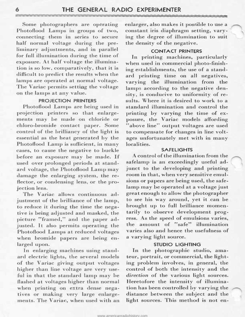
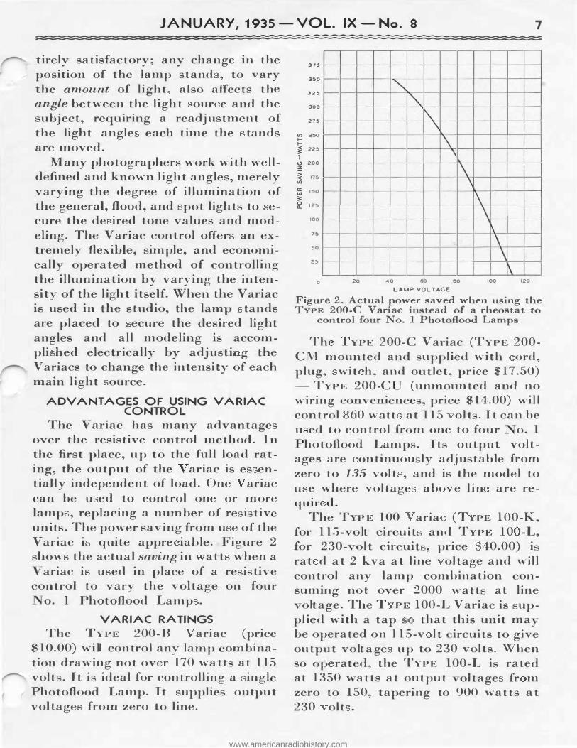
The Va ·iac has many advantages over the resistive control method. In the first place, up to the full load rating, the output of the ariac is es entially independent of load. One ariac can be u ed to control one or more lamp , replacing a number of re i tiv units. The power saving from u e of the Variac i quite appre iable. Figure 2
hows the actual saving in atts when a ariac is used in place of a re i tive
control to vary the voltage on four o. 1 Photo:flood Lamp .
VARIAC RATINGS The TYPE 200-B ariac (price
$10.00) will control any lamp ombination drawing not ov r 170 watt at 115 volt . It i ·deal for controlling a ingl Photofloo Lamp. t supplies output voltages from zero to line.
315
350
325
300
275
"' 2:>0 I-I-
� 225
l u 200 = > 175 < "' a: 150 w � 0 125 0..
100
75
50
25
0
-- -
--�
I-
20
""' "'
f'\. \ \
\ "
40 60 60
LAMP VOL TACE
\ \ \ \
\ \ \
\ 100 120
Figure 2. Actual power saved when using the TYPE 200-C Varia instead of a rheostat to
control four No. 1 Photoflood Lamps
Th YPE 200-C V adac (TYPE 200-
CM mounted and upplied with ord, plug, wit h, and o let, pri e $17.50)
-TYPE 200-C (unmounted and no wiring �onveni n e , price $14.00) will control 860 wa-tt at 115 olt . It can be u ed to control fr m one to four o. I
hoto:flood Lamp . t output voltages are ontinuou ly adjustable from zer to 135 volt , and is the model to use where voltage ab ve lin are requir d.
The T PE 100 ar·a (T PE 100-K ..
for 115- olt cir uit and TYPE 10 -L, for 230- olt cir uit , price 40.00) i rat d a t 2 kva at line oltage and will control any lamp combination onsuming not over 2000 watt at line
oltage. The T PE 100-L Varia is up-p1ied with a tap that this unit ma be operated on 115-v It ircuits to give output voltage up to 230 volts. When
o op rat d, the TYPE 100-L i rated at 1350 ' atts at output oltage fr m zero to 150, taper"ng to 900 watts at 230 olt .
www.americanradiohistory.com
8 THE GENERAL RADIO EXPERIMENTER
DIRECT-READING VARIABLE INDUCTORS
terminal posts on the upper right corner. The two oils may be pla ed either in rie or in parallel by mean of two link . The engraved pJat at the t p edge of the panel specifies the po iti n of the e links. The ale marked on the dial is for the eries onnection. of the
. coils, as in.di ated on the dial.
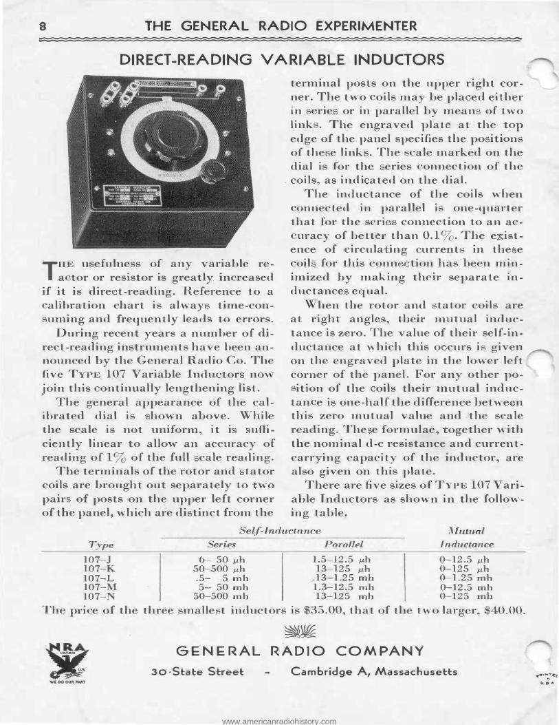
THE u efuln.ess of any variable rea tor or resistor is greatly in reased
if it is dire t-reading. Reference to a
The inductance of the coils when onnected in parallel is one-quarter
that for the seri connection to an acuracy of bett r than 0.1 . The e is-t
ence of circula ing urre t in the e oil for thi conn ti n has e n min
imized by making their separate inductance equal.
alibration chart is alway time-conmning and frequently leads to errors.
During recent years a number of direct-reading instruments have been announced by the General Radio Co. The five TYPE 107 Variable In.du tor no-\ join this n.tinually lengthening list.
The general appearance of the calibrated dial is hown above. While the scale is not uniform, it i u:fficiently linear to allow an accuracy of reading of 13 of the full cale reading.
The terminals of the rotor and tator coils are brought out separately to wo pair of posts on the upper left corner of the panel, which are distinct from the
hen the rotor and ta·tor coils are at righ·t angl s, their mutual inductance is zero. The value of their self-inductance at which this o curs i given on the engraved plate in the lower left corner of the panel. For any other po-
ition of the oils their mutual inductan e is one-half the difference betwe n thi zero mutual value and .the scale reading. The e formulae, ogether with the nominal d-c resistance and currentcarr ing capacity of the inductor, are also given on this plate.
There are five sizes of TYPE 107 Variable Inductors as shown in the following table.
Self-Inductance Mutual T pe eries Parallel Inductance
107-J 6-- 50 µh 1.5-12.5 µh 0-12.5 µh 107-K 50-500 .uh 13-125 µh 0-125 µh 107-L .5- 5 mh .13-1.25 mh 0-1.25 mh 107-M 5- 50 mh 1.3-12.5 mh 0-12.5 mh 107-N 50-500 :mh 13-125 mh 0-125 mh
Th pn e of the three smalle t inductors is $35.00, that of the two larg r, 40.00.
�� GENERAL RADIO COMPANY
30 ·State Street C.ambridge A, Massachusetts
www.americanradiohistory.com