Embed Size (px)
Citation preview
SFLC STANDARD SPECIFICATION 0850
2018 1 0850
GENERAL REQUIREMENTS FOR DRAWING PREPARATION
1. SCOPE
1.1 Intent. This specification establishes requirements for the uniform preparation of working and "as-
built" engineering drawings using various Coast Guard adopted industry specifications and standards.
The scope of “Drawing Preparation” may include either the revision of existing drawings to reflect
configuration changes or the development of new drawings to document new configuration information.
New drawing development includes both new drawings that didn't previously exist as well as new
drawings that are redrawn using the geometry from existing drawings.
1.2 Acronyms and term definitions. Below are definitions of various acronyms and terms that are used in
this standard or may be encountered in work item specifications.
CAD: Computer Aided Design.
CG-LIMS: Coast Guard Logistics Information Management System.
EC/TCTO: Engineering Change/Time Compliance Technical Order.
ESD-TIMB: Engineering Services Division, Technical Information Management Branch.
SFLC: Surface Forces Logistics Center.
SRD: Select Record Drawing.
STIP: Surface Technical Information Portal.
2. REFERENCES
COAST GUARD DRAWINGS
None
COAST GUARD PUBLICATIONS
Coast Guard Commandant Instruction (COMDTINST) M9000.6 (series), Naval Engineering
Manual, Chapter 085
Coast Guard Commandant Instruction (COMDTINST) M9085.1 (series), Naval Engineering
Computer Aided Design Standards
OTHER REFERENCES
None
NOTE
In the event of a conflict between the information or options presented in any
other drawing discipline specific reference typically used as an industry
standard or cited within Coast Guard Commandant Instruction
(COMDTINST) M9085.1(series), Naval Engineering Computer Aided Design
Standards, SFLC Standard Specification 0850 shall take precedence.
SFLC STANDARD SPECIFICATION 0850
2018 2 0850
3. REQUIREMENTS
3.1 Drawing Line Items. The Coast Guard will provide the Contractor with direction and scope within
the contractual documentation. Generally, tasks will fall into the following categories:
3.1.1 New drawings. All new drawing source files shall be prepared in a CAD format. New drawings will
be developed in accordance with SFLC Standard Specification 0850 and when necessary, utilize any of
the additional references cited above that apply to a particular drawing.
3.1.2 Drawings may be prepared in any CAD software, but the completed drawings must be submitted, in
single-file, multi-sheet format, and delivered in the AutoCAD “.dwg” file extension format, compatible
with AutoCAD version 2016 or earlier. Submittals shall include copies of all files used in the preparation
of the drawing sheets, including any product models. Drawings may be distilled from a 3D model into the
specified AutoCAD 2-Dimensional format if they meet these same provisions.
3.1.3 When in the design phase, all drawings shall begin with a revision designation of “1”. Subsequent
iterations or resubmissions shall have the revision designation incremented numerically. All numeric
revision write-up and triangles will remain until the drawing is completely approved by the CG. At that
time, the drawing shall have all revision indicators and entries in the revision block removed and the
revision designation shall become “-“ to indicate that this is the CG approved base line of the drawing.
Once under CG control, future revisions will be annotated with alpha characters.
3.1.4 Hand drawn sketches or red-lined reproductions provided as part of a Condition Found Report or a
Change Order Request are temporary drawings and are not considered a permanent part of the asset's
planset.
3.1.5 Revisions to existing drawings: Revisions may be completed on U.S. Coast Guard supplied master
AutoCAD files. In cases where legacy source drawings exist in non-CAD formats, revisions will be made
on the Mylar drawings, tracings, or sepias provided. With approval from TIMB, PDF renditions of a
document may be revised when an original source file is unavailable (See Section 3.31.1.4). All drawing
revisions shall be completed in accordance with this standard specification.
3.2 Drawing types. There are four CG drawing types: Hull, Mechanical & Electrical (HM&E);
Procurement, Contract Guidance, and Bills of Materials. When creating a new drawing for any drawing
type, a drawing number shall be requested in CG-LIMS STIP before work on the drawing begins.
3.2.1 Hull, Mechanical & Electrical (HM&E). These drawings are a permanent representation of an asset
that will be revised throughout the lifecycle of the asset.
3.2.1.1 Fleet Drawings are HM&E drawings that define a system or part that is used on more than one
Platform Class.
3.2.2 Procurement. These drawings are not part of any asset’s structure or systems. They are used to detail
items and parts that are used aboard the asset or throughout the CG such as; Flags, eating utensils, awards
folders, USCG medals, etc…
3.2.3 Contract guidance. These drawings are developed by or for the CG to provide general or detailed
direction to a shipbuilder or contractor. Contract Guidance drawings should also be used to detail removal
and installation of systems on an asset.
3.2.3.1 When a drawing package is required for equipment or system installation, removal, or for general
SFLC STANDARD SPECIFICATION 0850
2018 3 0850
contract guidance, the necessary data from each Ships Work Breakdown Structure (SWBS) group should
be packaged together to make an Installation/Removal/Guidance (IRG) drawing. The IRG shall be a
Contract Guidance drawing comprised of pertinent portions of existing baseline drawings, from any
SWBS group, required to detail the change. If the IRG drawing contains data from only one SWBS, that
SWBS can be used in the drawing number. If the IRG drawing contains data pulled from multiple SWBS,
the drawing number will have an 802 SWBS. The IRG drawing shall be utilized for the prototype
installation/removal of a system, and shall be redlined by the installation team with any deviations from
the original design.
3.2.3.2 Once the redlined IRG drawing receives approval from the project manager and the appropriate
product line, the data contained therein shall be used to revise existing baseline drawing(s) within the
appropriate SWBS group(s). New drawings shall be created when the data to be presented involves a new
system or equipment that cannot otherwise be integrated appropriately by revising an existing drawing.
The IRG drawing itself shall not be used to satisfy this requirement. The IRG shall be canceled once the
data has been disseminated into the appropriate baseline drawing(s) or made into new drawing(s) within
the HM&E document type. IRG drawings shall not be considered a final product detailing the change and
will not be entered into CG-LIMS-STIP as part of an Active plan set. Non-SRD drawings shall be
updated at the project manager’s or Product Line’s discretion. A Contract Guidance drawing number shall
be requested from SFLC-ESD-TIMB thru CG-LIMS STIP for all IRGs.
3.2.4 Bill of Material (BM). BMs are a legacy drawing that identified all parts associated with an asset for
all major systems. While BM’s are no longer developed for new CG acquisitions, they are still maintained
for legacy assets.
3.2.5 Other file types that can be considered a drawing. Excel, Word, and Access, can be accepted at the
CG’s discretion. Sheet 1-2 templates are located on the CG Portal Page. All non-CAD drawings shall
abide by the requirements set forth in this standard where applicable.
3.2.6 If another file type is to be accepted by the CG, it must at a minimum, have the following:
Signature block
Revision history block
Distribution statement
An assigned drawing number
Applicability block
3.3 Format. All new drawings and revisions to existing drawings shall be delivered to SFLC-ESD-TIMB
in AutoCAD™ 2016 compatible (.dwg) file format and in accordance with Naval Engineering Manual
M9000.6 (Series).
3.3.1 2D Drawings extracted from a 3D Product Model shall be fully compatible with AutoCAD™ (latest
USCG agreed to version) without the use of any add on or viewer programs. External References (X-
Refs), proxy graphics or non-editable block or graphics shall not be used.
3.3.2 Drawings prepared in data processing systems (text and graphics processing). If data processing
systems other than AutoCAD are used to prepare drawings, text and graphics must be imported and
embedded into the AutoCAD file and must follow standards in accordance with M9085.1. Text and
graphic files must be readable and allow for modification and editing within AutoCAD™ or the
Microsoft ™ Office Suite without the use of additional software.
3.3.3 Drawings may be prepared in discipline specific software or other applications that are in an
SFLC STANDARD SPECIFICATION 0850
2018 4 0850
AutoCAD™ 2016 compatible (.dwg) file format and shall be capable of being viewed, printed and
modified without the use of the original generating program or any Object Enabler plug-in.
3.3.4 All drawings developed by or specifically for the USCG shall utilize the USCG drawing border
templates. The USCG will provide these templates to any contractor doing work for the CG.
3.3.5 Sheet Subtitles and Layout/Sheet Tabs.
3.3.5.1 In each Title Block, Subtitles shall be used to identify all sheets. The Subtitle should generally
identify the data on that sheet. Subtitles are required for each sheet in the Index block.
3.3.5.2 Layout Tabs shall be named with the drawing sheet number only (e.g. 1, 2, 3, 3A, etc.) and shall
be sequential from left to right.
3.3.6 Paper space. The border templates containing the standard attributable blocks required by this
Manual shall be utilized and are created in paper space at 1:1 scale. The actual physical components
depicted shall be at full scale (1:1) in model space and scaled viewports utilized. Viewports shall be on
layer “0-Viewport.” Viewport scale shall coincide with the scale bar (Imperial or Metric scale) on the
sheet and be identified in the scale Callout.
3.3.6.1 For Metric drawings, border templates shall be scaled up by a factor of 25.4. Plot Scale shall be
set to “1:1” with 1 mm = 1 units for plotting the drawing to actual paper size.
3.3.6.2 Existing model space drawings undergoing revision need not be converted to paper space unless
specifically stated in the contract or statement of work.
3.3.7 Drawing layering convention. Layer naming systems shall be used and based on the specific usage
of the drawing information. Layer naming systems shall be used to distinguish system types, component
sizes and/or materials, manufacturing data, geometric location or orientation, type of drawing entity, or
other uses specific to the needs of the user. The following general guidance shall be applied to all
drawings:
3.3.7.1 No entities may be drawn on layer “0” (zero) except elements of blocks. Blocks with internal
layering may be inserted on layer “0” (zero).
3.3.7.2 At a minimum, layering systems shall provide at least one separate layer for each of the following
elements and contain at least one descriptive word such as provided in all CG border Templates:
Notes and other text not part of dimensions
Dimensions
Reference or construction lines that do not represent actual material or structure, such as
baselines, centerlines, lines of frames, perpendiculars, etc.
Systems, structure or components used as background, not ordered or modified by the
drawing.
Specialized information such as weight data.
Drawing features such as section or detail cut lines, break lines, and similar non-physical
entities.
3.3.7.3 Revision entities outside of the revision history block such as revision triangles, hashing and
revision clouds shall be on a separate layer for each revision. Note that this does not require that the
SFLC STANDARD SPECIFICATION 0850
2018 5 0850
drawing elements inserted at a revision be on a separate layer, (though this is not prohibited either).
3.3.7.4 Layer “No-Plot” and “0-Viewport” may be used for any information that should be visible on the
drawing but not be plotted. Layers used within a standard Coast Guard drawing template may be copied,
modified, renamed, or deleted as required.
3.3.8 Blocks and shapes. No blocks subject to copyright or other licensing restrictions may be used in any
drawing.
3.3.8.1 All block and shape files used, including those automatically produced by proprietary software,
shall be provided to the Coast Guard with no license restrictions controlling use, modification of, or
distribution of the drawings containing these blocks or shapes. Proprietary software, which does not
comply with this requirement, shall not be used for developing Coast Guard drawings.
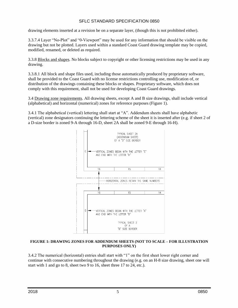
3.4 Drawing zone requirements. All drawing sheets, except A and B size drawings, shall include vertical
(alphabetical) and horizontal (numerical) zones for reference purposes (Figure 1).
3.4.1 The alphabetical (vertical) lettering shall start at “A”. Addendum sheets shall have alphabetic
(vertical) zone designators continuing the lettering scheme of the sheet it is inserted after (e.g. if sheet 2 of
a D-size border is zoned 9-A through 16-D, sheet 2A shall be zoned 9-E through 16-H).
FIGURE 1: DRAWING ZONES FOR ADDENDUM SHEETS (NOT TO SCALE – FOR ILLUSTRATION
PURPOSES ONLY)
3.4.2 The numerical (horizontal) entries shall start with “1” on the first sheet lower right corner and
continue with consecutive numbering throughout the drawing (e.g. on an H-8 size drawing, sheet one will
start with 1 and go to 8, sheet two 9 to 16, sheet three 17 to 24, etc.).
SFLC STANDARD SPECIFICATION 0850
2018 6 0850
3.5 External references. The current Coast Guard drawing management system does not allow for the
tracking and control of external reference files (XREFs). Therefore, all XREFs shall be bound or inserted
into the drawing file before delivery to SFLC-ESD-TIMB.
3.6 3D Models. All 3D Technical Data Packages (TDP) shall be developed in accordance with MIL-STD-
31000. The 3D Product Model shall be in an ISO 10303 STEP compliant format.
3.6.1 Tessellation lines may appear on drawings if desired. Hidden line removal, if required, shall be set.
Proper drawing plotting shall not require the user to set hide options prior to plotting.
3.6.2 Three dimensional models, (solids, wire frames, or surfaces) are acceptable.
3.6.3 Shading or rendering, while permitted shall not be required to view or plot a drawing, and drawings
shall be clear and understandable without the use of shading or rendering.
3.6.4 Dimensions. All dimensions shall be in paper space layout with a DIMASSOC value of 2. All
DIMSTYLES shall adhere to the following:
Dimensions shall be associative and shall not be exploded.
Dimension styles preloaded within the border template shall be used, and modified for scale
purposes only when necessary.
Dimension style STANDARD shall not be used. Fractional dimension shall be “Not
Stacked”.
Dimension appearance (1/8" closed arrows, 'CG_ROMANS' text style, 1/8" text height, 'Not
Stacked' fractions, etc.) shall remain consistent with all present and new dimstyles.
Fractional unit (CG-FRAC) dimstyles add an inch mark (") to the dimension as a suffix and
shall not be used for angular dimensions. These dimstyles are generally used for objects
measuring up to 72".
Architectural unit (CG-ARCH) dimstyles are generally used for objects measuring 6'-0" and
over.
Millimeter with inch unit (CG-MMIN) dimstyles are used when the border template
geometry and associated blocks have been scaled up by a factor of 25.4.
Paper space (PS) dimstyles automatically scale to the viewport when the variable
'DIMASSOC' is set to two (2).
Scale factor (SF) dimstyles are used in paper space but have a 'measurement scale factor'
(DIMLFAC) assigned. Note that these ‘SF’ styles must have the variable 'dimassoc' set to
one (1) to work properly. These dimstyles may be copied and renamed to accommodate
additional scales if the 'DIMLFAC' is changed to match the scale factor.
3.7 Text styles. Text height shall not be set any smaller than 0.1 inches, and shall be in accordance with
ANSI-Y14.2. Text not used for special purposes such as illustration of actual labels, shall be
"Romans.shx" font. Text width shall be .8 but may be set as required for the text style. All text shall be in
Paper space and on layer “Text” or “Dimensions” unless the text is embedded in the block geometry.
3.8 Line types. Only the line types supplied with AutoCAD™ 2016 shall be used.
SFLC STANDARD SPECIFICATION 0850
2018 7 0850
3.9 Color usage. All drawings created or revised in AutoCAD shall have the background set to Black. All
drawings shall be created using colors visible both in the electronic .dwg file as well as on plotted
drawings. The list of CG authorized colors for plotting are embedded in each CG Border template.
3.10 Line weights. Each USCG Drawing template has a predefined line weights set up. These line
weights should not be altered by a contractor without consent from the USCG.
3.11 Revision symbol block. An attributable block, triangle style revision symbol (Rev Triangle) shall be
used to identify changes made during a revision to a drawing. The Rev Triangle shall have the appropriate
Rev letter inside the triangle and the revision number in superscript at the top right outside the triangle
(see REVTRIBLK on any standard template). Other attributes embedded on the Rev Triangle block are
for amplifying information but are not required.
3.12 Computer Oriented Wiring Diagram (COED's). All COED's shall adhere to the following two part
formatting constraints:
3.12.1 Cover sheets. The cover sheet(s) shall consist of one, multi-sheet file on standard horizontal A
sized borders. At a minimum these sheets should include:
Sheet one shall have: Coast Guard Title, Drawing Number Block, USCG Approval Block,
Command or Contractor Block, Revision History Table, Applicability Table, Sheet Revision
Status Table, Special Notations Table and Reference Plans Table.
The COED DATABASE LINK section is reserved for SFLC, ESD, Technical Information
Management Branch use and should not moved or altered.
3.12.1.1 Sheet 2 is meant as a continuation of sheet one for information and or data that does not fit on in
the blocks on sheet 1. If needed, the Materials List Table should go on sheet 2.
3.12.2 Cable database. The Cable Database shall be in Access format, utilizing the standard Coast Guard
COED Template. The database report will consist of two or three separate reports generated from the
Access Database COED Template. These reports are located in the reports section of the database and are
as follows:
3.12.2.1 Cable Run Report (Mandatory). Contains origin and destination information for cables, also
includes length and cable type
3.12.2.2 Final Report (Mandatory). Contains origin and destination information for cables as well as
special instructions, point-to-point information for all conductors of the cables, connectors and revision
notation
3.12.2.3 Sleeving Report (Optional). Generates a report for the label designations for all individual
conductors
3.12.3 COED cover sheets and database templates can be found on the SFLC website.
3.13 Proofing and performing preliminary drawing check-off. The Contractor shall purge the drawings of
unused block definitions, layers, line types, etc. (except for special layers which may be required for
assignment drawings in supplemental CAD policies) to keep file size to a minimum.
Remove any extraneous data in Model Space and outside the drawing borders in Paper Space.
If the drawings were associated with a sheet set, the association to the sheet set must be
purged from each drawing prior to submission, to avoid the lost set association error. To
SFLC STANDARD SPECIFICATION 0850
2018 8 0850
remove the association, open the drawing in the absence of the sheet set file, and select
remove on the Lost Set Association dialog, and save.
Delete any unused layout tabs.
Delete any unattached XREF paths & bind any XREF.
ZOOM to EXTENTS and save drawing.
Save in format compatible with AutoCAD 2016 drawing format.
Delete any geometry present in Model Space that is not depicted in any Layout unless needed
for design development.
Drawing Signature Authority.
3.14 Authorized signature authorities. Newly created drawings and revisions to existing drawings require
the signature of a designated Coast Guard authority to become part of the official Coast Guard drawing
planset. Authorized signature authorities for new and revised drawings are listed below:
3.14.1 Major acquisitions:
Project Resident Office or Commandant (CG-9) Program Office
3.14.2 Non-Major acquisitions:
Commandant (CG-9) Program Office
Commandant (CG-7) Capability Office
Commandant (CG-45) Office of Naval Engineering
3.14.3 Hull, Mechanical and Electrical for sustainment of Surface Assets
SFLC-ESD-Naval Architecture & Marine Engineering Branch (NAME)
o Naval Architecture Section Chief
o Main Propulsion Machinery Section Chief
o Auxiliary Machinery Section Chief
o Electrical Systems Section Chief
SFLC-ESD-Technical Information Management Branch (TIMB)
o Branch Chief (Non-engineering changes)
USCG Yard Engineering
o Electrical/Electronic Section Chief
o Mechanical Section Chief
o Hull Section Chief
Product Lines
o Product Line Manager
o Product Line Engineer
Command, Control, Communications, Computers and IT drawings (C4IT)
o C4ITSC and Project Resident Office (PRO)
o Command Appointed Engineering Authority
3.14.4 For new drawings, signature approval in the Title Block on sheet one of a multi-sheet drawing
constitutes approval of all sheets of that drawing. Approval signatures are not required on subsequent
sheets of the same drawing.
SFLC STANDARD SPECIFICATION 0850
2018 9 0850
3.14.5 For drawing revisions, signature approval is only required in the Revision Block with the latest
revision write up. Both the draftsman completing the revision and the approval authority shall date, add
his/her first initial, full last name and organization of the approving official in the revision history block.
The approval signatures in the revision history block constitute approval of all portions of that revision.
3.14.6 For AutoCAD™ drawings, both new and revised, printed names (i.e. text) with the suffix
designator "/s/" shall represent drawing approval signatures.
3.15 Drawing numbers and title block numbering convention. All drawings relating to cutters, boats, and
installations thereon shall be assigned a Coast Guard drawing number issued by Surface Forces Logistics
Center, Engineering Services Division, Technical Information Management Branch (SFLC-ESD-TIMB)
in accordance with the Naval Engineering Manual, COMDTINST M9000.6 (series).
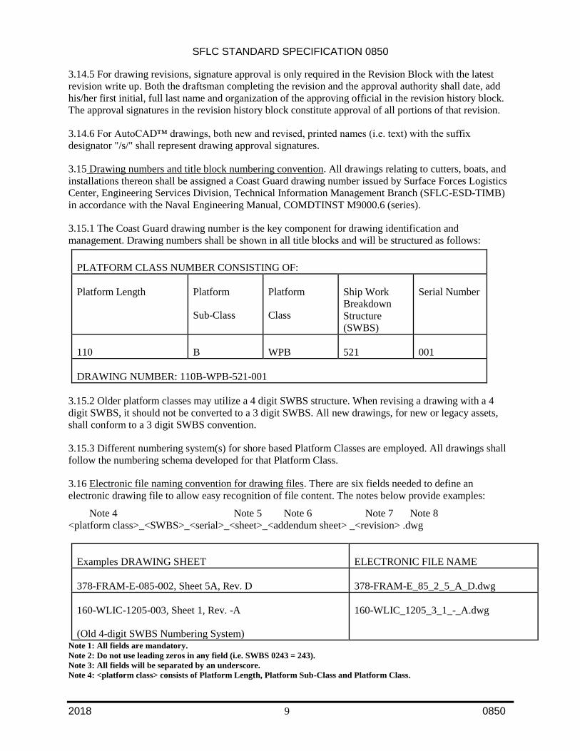
3.15.1 The Coast Guard drawing number is the key component for drawing identification and
management. Drawing numbers shall be shown in all title blocks and will be structured as follows:
PLATFORM CLASS NUMBER CONSISTING OF:
Platform Length Platform
Sub-Class
Platform
Class
Ship Work
Breakdown
Structure
(SWBS)
Serial Number
110 B WPB 521 001
DRAWING NUMBER: 110B-WPB-521-001
3.15.2 Older platform classes may utilize a 4 digit SWBS structure. When revising a drawing with a 4
digit SWBS, it should not be converted to a 3 digit SWBS. All new drawings, for new or legacy assets,
shall conform to a 3 digit SWBS convention.
3.15.3 Different numbering system(s) for shore based Platform Classes are employed. All drawings shall
follow the numbering schema developed for that Platform Class.
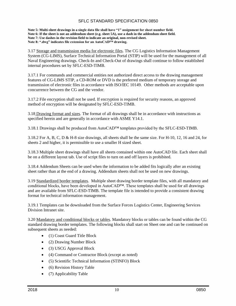
3.16 Electronic file naming convention for drawing files. There are six fields needed to define an
electronic drawing file to allow easy recognition of file content. The notes below provide examples:
Note 4 Note 5 Note 6 Note 7 Note 8
<platform class>_<SWBS>_<serial>_<sheet>_<addendum sheet> _<revision> .dwg
Examples DRAWING SHEET ELECTRONIC FILE NAME
378-FRAM-E-085-002, Sheet 5A, Rev. D 378-FRAM-E_85_2_5_A_D.dwg
160-WLIC-1205-003, Sheet 1, Rev. -A
(Old 4-digit SWBS Numbering System)
160-WLIC_1205_3_1_-_A.dwg
Note 1: All fields are mandatory.
Note 2: Do not use leading zeros in any field (i.e. SWBS 0243 = 243).
Note 3: All fields will be separated by an underscore.
Note 4: <platform class> consists of Platform Length, Platform Sub-Class and Platform Class.
SFLC STANDARD SPECIFICATION 0850
2018 10 0850
Note 5: Multi-sheet drawings in a single data file shall have “1” assignment for sheet number field.
Note 6: If the sheet is not an addendum sheet (e.g. sheet 5A), use a dash in the addendum sheet field.
Note 7: Use dashes in the revision field to indicate an original, non-revised sheet.
Note 8: “.dwg” indicates file extension for an AutoCAD™ drawing.
3.17 Storage and transmission media for electronic files. The CG Logistics Information Management
System (CG-LIMS), Surface Technical Information Portal (STIP) will be used for the management of all
Naval Engineering drawings. Check-In and Check-Out of drawings shall continue to follow established
internal procedures set by SFLC-ESD-TIMB.
3.17.1 For commands and commercial entities not authorized direct access to the drawing management
features of CG-LIMS STIP, a CD-ROM or DVD is the preferred medium of temporary storage and
transmission of electronic files in accordance with ISO/IEC 10149. Other methods are acceptable upon
concurrence between the CG and the vendor.
3.17.2 File encryption shall not be used. If encryption is required for security reasons, an approved
method of encryption will be designated by SFLC-ESD-TIMB.
3.18 Drawing format and sizes. The format of all drawings shall be in accordance with instructions as
specified herein and are generally in accordance with ASME Y14.1.
3.18.1 Drawings shall be produced from AutoCAD™ templates provided by the SFLC-ESD-TIMB.
3.18.2 For A, B, C, D & H-8 size drawings, all sheets shall be the same size. For H-10, 12, 16 and 24, for
sheets 2 and higher, it is permissible to use a smaller H sized sheet.
3.18.3 Multiple sheet drawings shall have all sheets contained within one AutoCAD file. Each sheet shall
be on a different layout tab. Use of script files to turn on and off layers is prohibited.
3.18.4 Addendum Sheets can be used when the information to be added fits logically after an existing
sheet rather than at the end of a drawing. Addendum sheets shall not be used on new drawings.
3.19 Standardized border templates. Multiple sheet drawing border template files, with all mandatory and
conditional blocks, have been developed in AutoCAD™. These templates shall be used for all drawings
and are available from SFLC-ESD-TIMB. The template file is intended to provide a consistent drawing
format for technical information management.
3.19.1 Templates can be downloaded from the Surface Forces Logistics Center, Engineering Services
Division Intranet site.
3.20 Mandatory and conditional blocks or tables. Mandatory blocks or tables can be found within the CG
standard drawing border templates. The following blocks shall start on Sheet one and can be continued on
subsequent sheets as needed:
(1) Coast Guard Title Block
(2) Drawing Number Block
(3) USCG Approval Block
(4) Command or Contractor Block (except as noted)
(5) Scientific Technical Information (STINFO) Block
(6) Revision History Table
(7) Applicability Table
SFLC STANDARD SPECIFICATION 0850
2018 11 0850
(8) Sheet Revision Status and Title Index Table
(9) Special Notations Table
(10) Weight Control Table (if applicable)
(11) Reference Plans Table
(12) General Notes Block
(13) Materials List Table (except A and B size drawings)
3.20.1 Scale Bar dynamic blocks are mandatory for each viewport with scalable geometry. Only one scale
is needed for a sheet containing multiple viewports of the same scale. The block is not required for
geometry drawn at a scale of 1:1.
3.20.2 All lists shall utilize AutoCAD Tables verses multiline text.
3.20.3 For new drawings, all tables may be continued onto sheet 2, then sheet 3 and so on as needed. For
revisions to existing drawings, the tables can be continued on an addendum sheet to the last sheet that has
the table on it.
3.20.4 Mandatory attributable blocks shall not be modified with the exception of Command or Contractor
Approval Signature Block (CCBLK).
3.20.5 For new drawings, the Materials List Table may be continued on sheet 2 as needed. For Revisions
to drawings, if additional space is needed for the Materials Table, it shall continue onto an addendum
sheet to the last sheet that had a Materials List Table on it. All material identified on the drawing shall be
listed in one Materials List table. Additional columns may be added to the Material List Table for
amplifying information as needed.
3.20.6 Materials list exception. Due to the rapid pace of cyber-IT component advances, and their virtual
obsolescence upon installation, all routers, servers, switches managed by the C4IT community will be
identified as such in a materials list, however these items will be treated as generic parts that do not
require supporting logistic details (i.e., Part Number, CAGE Code, Manufacturer ID, etc.) within the Parts
List block. These generic components, when replaced, will not trigger a revision of Selected Record
Drawings impacted.
3.21 Standard revision practices. The following standard drawing revision practices shall be observed.
These practices are generally in accordance with MIL-STD-31000 Technical Data Packages and ANSI-
Y14.100. Additional information may be found in those documents or commercially prepared
compilations of those documents for industry use. For specific questions and assistance, contact SFLC-
ESD-TIMB. All drawings must be checked out of CG-LIMS STIP before beginning the revision. When
requesting Hard Copy drawings, once the check-out process has been initiated in CG-LIMS STIP, Hard
Copy drawings can be acquired by contacting SFLC-ESD-TIMB.
3.21.1 Revision to Master Drawings only. All revisions must be completed on the master file, paper or
CAD files. All drawing master files are maintained in the SFLC-ESD-TIMB drawing repository. Master
Drawings in hardcopy format shall be stamped in red ink with the following note: THIS DRAWING IS
THE MASTER DRAWING ONLY IF THIS NOTE IS IN RED INK (not all master drawings in the
Coast Guard's files have been stamped yet). If this stamp is not in red ink, or if a stamp is present saying
"FILE COPY", or "SFLC COPY", do not revise without specific direction from SFLC. A DRAFT
revision to a drawing may be prepared on a reproducible copy (or on a print copy) only if that copy's title
block is hatch-marked out and a large-lettered flag stating: "UNOFFICIAL DRAWING: FOR DRAFT
REVISION PURPOSES ONLY" is prominently displayed immediately adjacent to the hatched-out title
SFLC STANDARD SPECIFICATION 0850
2018 12 0850
block.
3.21.2 Drawings should be revised when the extent of drawing changes are minor relative to the amount
of data that will be retained in the drawing.
3.21.3 Hard copy drawings. The old portions can be hashed out and new details should be created on
additional sheets in AutoCAD. Revisions to text can be erased or hashed out and new information can be
hand drawn on the hard copy or added to an additional AutoCAD sheet. If a sheet is deleted, the title
block of the deleted sheet shall be hashed out. A revision triangle block shall be placed next to the hashed
out title block indicating the revision that deleted that sheet. The words “THIS SHEET DELETED BY
REVISION xx” should also appear next to the title block utilizing the largest practical font size.
3.21.4 Bills of Material in Hard Copy format. When an item identified in a Bill of Material needs to be
revised, the item shall be lined out on the Hard Copy (except for the Item and Piece Number), and the
replacement item shall be added via an AutoCAD sheet. The Item Number will be the next sequential
number for the entire BoM, and the piece number shall be carried forward to the new item number. A
revision triangle shall be place next to the lined out item on the Hard Copy BoM and he revision write-up
shall detail the change to the new Item Number.
3.21.5 CAD files: Old geometry, details and text shall be hatched out or lined out and new data added on
existing sheets, or on additional CAD sheets. Exceptions: if a change can be fully defined in the revision
write-up, it is permissible to delete the geometry, details and text that are being revised.
3.21.6 Retaining Historical Data: Revisions should be detailed in the Revision block with as much
clarification as practical. Ideally, it should be possible to reconstruct the previous version of the drawing
simply by undoing the changes described in the revision column. Thus the revision column itself should
detail every change made, using wording that describes the change as accurately as possible, such as
"ADDED DETAIL 9-F", "DELETED REF 16", or "RV-7 SET PRESS WAS 60 PSI". Note in the last
case that it would be redundant to say "CHANGED RV-7 SET PRESS FROM 60 TO 75 PSI", because
the body of the drawing already shows the set pressure as 75 psi. It is not necessary to hatch out deleted
geometry and data. All historical versions of a drawing are maintained by SFLC-ESD-TIMB.
Additionally, all original drawings and prior revisions can be viewed and downloaded via CG-LIMS-
STIP to ascertain previous configurations.
3.22.4 If a revision needs to be made to an original hard-copy drawing and the revised data will be created
using AutoCAD, all sheets of that drawing shall be converted to AutoCAD for uniformity when possible.
3.21.7 Give Reason for Revision. Each revision write-up should begin with a brief description
documenting the reason for the revision, such as "TO SUIT ENGINEERING CHANGE (number):
REPLACE BEARING MATERIAL". The description should provide what project, EC, or documentation
that initiated the change. In the event multiple ECs are incorporated in the revision, the revision write up
must clearly delineate the changes corresponding to each EC. Additional cross-reference information
supporting the reason for revision (Contract, CLIN, Activity, Project #, Service Bulletin, etc), is
encouraged to also be entered in revision history.
3.22 Revision status. Sheet one of all drawings shall always contain the highest revision designator in the
Title block of the drawing, while each remaining sheet shall carry the revision designator associated with
the latest revision affecting that individual sheet. Sheet one shall have a Sheet Revision Status and Title
Index table, which shall indicate the revision designator of each sheet of the drawing.
3.22.1 Each time a drawing is revised a revision symbol is added to each sheet where changes are made.
SFLC STANDARD SPECIFICATION 0850
2018 13 0850
In cases where there are multiple revisions to a complex detail, it is permissible to add just one revision
triangle next to the “Call-out” of the detail.
3.22.2 The Revision History Table shall be updated accordingly. A revision triangle is not to be placed
next to the Revision History Table to indicate the change to the table, nor should this change be
documented in the revision write-up.
3.22.3 The revision designator for a drawing shall be identified by an upper case letter or letters (except in
Conceptual/Prototype drawings). Each new drawing created shall begin with the “tack” symbol (-) in the
Title block. The first revision shall then be identified by "A". Successive changes shall use the next
sequential letter, except that the letters "I", "O", "Q", "S", "X", and "Z" shall not be used. Upon
exhaustion of the alphabet, sequential revisions shall be "AA", "AB", etc., and then "BA", "BB", etc.
3.22.4 On legacy drawings where numbers have been used instead of letters for revision designators, the
use of numbers shall be continued in the spirit of an authorized deviation for current convention.
3.23 Revision history block. All revision notes shall be placed in a revision history block beginning on
sheet one and continued on a 2A addendum sheet as needed.
3.23.1 A triangular revision identifier shall be placed adjacent to all revised areas, except where the entire
sheet has been added by revision. Where multiple items are being revised under the same revision, each
item or group of items shall be identified with a superscript number outside the revision symbol that
relates to the revision notes in the Revision History Table. The CG approved Rev Triangle block
(REVTRIBLK) can be found on all CG border templates.
3.24 Revision Procedure for Special Situations.
3.24.1 Master Drawing Not Yet Available. This situation arises when master engineering drawings have
not yet been accepted from the shipbuilder, and changes need to be made to a system(s). In this instance, a
new engineering drawing shall be created for the purpose of documenting needed changes. The new
master engineering drawing will be retained by SFLC-ESD and will be available for documenting
changes until the complete master engineering drawings are received from the shipyard.
3.24.2 For drawings that will be based from the shipbuilder’s drawings, the drawing number and title of
the new master engineering drawing shall be the same as the shipbuilders drawing except for the series
number, and have the shipbuilders drawing number in parenthesis added to the end of the title. The serial
number shall be changed sufficiently to identify that it is a modification to an un-released OEM drawing
(typically beginning with series number 500).
3.24.3 For drawings created by entities other than the asset’s original builder, a new drawing number will
be established with the appropriate SWBS and the title shall be unique to the system being depicted. All
efforts should be made to ensure this title is not a duplicate of any of the shipbuilder’s original drawing
titles.
3.24.4 When the only copy of a drawing is in PDF format, every effort should be made to convert the
PDF to an AutoCAD file. With permission from TIMB, a PDF can be revised via raster or overlay of the
PDF into an AutoCAD file. The needed changes should be done via AutoCAD, and then Save to PDF.
The newly created PDF would then be the master file for that revision. A hard copy can be plotted from
the PDF if needed.
3.25 Superseding a drawing. Drawings should be superseded if extensive revisions are required or if the
SFLC STANDARD SPECIFICATION 0850
2018 14 0850
quality of the existing hard copy master engineering drawing is poor (e.g. torn, faded, smeared, etc.). If a
drawing is superseded, the following steps shall be followed:
3.25.1 Superseded Drawing.
The act of superseding a drawing constitutes a revision to that drawing. Thus the following
revisions should be made:
Hatch out the title block on all sheets, except for the revision letter.
As a result of the drawing being superseded, the revision letter shall be increased.
Add (in bold characters) immediately adjacent to the title block of sheet 1: "THIS
DRAWING HAS BEEN SUPERSEDED BY USCG DWG XXX."
The Revision History block should be annotated with a brief description as to why the
drawing was superseded. I.E “THIS DRAWING WAS SUPERSEDED DUE TO
EXTENSIVE CHANGES IN THE --- SYSTEM.”
3.25.2 Superseding Drawing.
The new superseding master engineering drawing shall be in AutoCAD and carry a new
USCG drawing number.
The new drawing shall be a "clean" drawing. All revision symbols, cross-outs, entries in the
Revision History block, etc…, from the superseded drawing shall not be reconstructed on the
superseding drawing.
The original issue of the superseding drawing shall be REV "-", and the revision column shall
be annotated as follows "THIS DRAWING WAS CREATED BECAUSE (brief
description)."
The superseding drawing will have new Design, Drawn, Checked and Approval signatures.
3.26 Canceling a drawing. If a drawing no longer contains useful or applicable information, the drawing
shall be canceled. If a drawing is cancelled, the following steps shall be followed:
Hatch out the title block on all sheets, except for the Revision letter.
As a result of the drawing being canceled, the revision letter shall be increased.
Add (in bold characters) immediately adjacent to the title block "THIS DRAWING HAS
BEEN CANCELED.”
The Revision History block should be annotated with a brief description as to why the
drawing was canceled. I.E. “THIS DRAWING WAS CANCELED IN ACCORDANCE
WITH ENGINEERING CHANGE # XXXX. (Brief explanation such as: THIS SYSTEM
HAS BEEN REMOVED WITH NO REPLACEMENT.)”
3.27 Revisions when Master Select Record Drawing (SRD) is unavailable. This situation arises for
example when Master SRD Drawings have not yet been received from the shipbuilder and changes need
to be made to certain systems, the following actions should be taken:
3.27.1 A single, new Master Drawing for each appropriate set of drawings shall be created, which may be
based from current, but un-editable vendor drawings, for the purpose of documenting needed changes.
This drawing will have a special branching drawing number, issued by TIMB, that identifies it as an
addendum to the original vendor’s master drawing. This new Master Drawing will be available for
depicting various needed changes until the complete Master Drawings are received from the shipyard. At
such time, the two drawings shall be incorporated back into one class SRD drawing.
SFLC STANDARD SPECIFICATION 0850
2018 15 0850
3.27.2 The title of this new Master Drawing shall be "CHANGES TO (Original Title)", and the following
note shall be displayed prominently on sheet one near the title block: "THIS DRAWING WAS
CREATED FOR THE PURPOSE OF DOCUMENTING CHANGES WHEN THE ORIGINAL
MASTER DRAWINGS WERE NOT AVAILABLE FOR REVISION."
3.27.3 It is mandatory that this new Master Drawing make reference (by drawing number in a List of
References on Sheet 1) to the (absent) system drawing. The List of References will be used as a "tickler"
to update the absent Master Drawings when received.
3.27.4 When the (previously-absent) Master SRD Drawing becomes available, it is mandatory to revise
the vendor’s master class drawing with the addendum drawing. The applicable Product Line will be
responsible to fund the maintenance/repair contractor to modify the SRD drawing if it becomes available
during the availability timeframe. However, once the maintenance/repair contract is complete, the PL will
be responsible to incorporate the changes, to contract work to outside vendors qualified to perform the
work, or to initiate and negotiate activities with SFLC-ESD-NAME to perform the required
engineering/CAD services.
3.28 Drawing views. All drawing views shall be identified with a “Callout”. The Callout is generally
placed below and in the middle of the view. The zone of the Callout shall have the horizontal numerical
zone followed by a “dash” and then the vertical alpha character. The views zone number and letter for the
title shall come from where the center of the Callout block is located in the body of the drawing (e.g.
“PLAN VIEW 5-A” has the callout block located in horizontal zone “5” and vertical zone “A”). This
pertains to all views, even if the view expands into multiple zones of the drawing sheet.
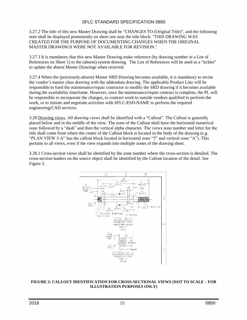
3.28.1 Cross-section views shall be identified by the zone number where the cross-section is detailed. The
cross-section leaders on the source object shall be identified by the Callout location of the detail. See
Figure 2.
FIGURE 2: CALLOUT IDENTIFICATION FOR CROSS-SECTIONAL VIEWS (NOT TO SCALE – FOR
ILLUSTRATION PURPOSES ONLY)
SFLC STANDARD SPECIFICATION 0850
2018 16 0850
3.29 Plotting instructions. Plotting shall be in accordance with USCG Color-Dependent Plot Style Table
as shown on all CG drawing templates.
3.29.1 Normal layer line width and visibility. All layers will normally be on. Layer “no-plot” shall have
plotting turned off. Drawings requiring other plotting instructions must have the special plotting
instructions prominently visible on layer “No Plot”.
3.29.2 Special plotting instructions. All special plotting preferences will be noted in the USCG Color-
Dependent Plot Style Table in the upper right-hand corner of the drawing template.
SFLC STANDARD SPECIFICATION 0850
2018 A1 0850
APPENDIX A INSTRUCTIONS FOR COMPLETING ATTRIBUTE BLOCKS
A1. SCOPE
A1.1 Intent. This appendix establishes requirements for the attribute blocks.
A2. REQUIREMENTS
A2.1 Coast Guard Title with USCG Approval Block.
1. LENGTH: Enter the length of the vessel or standard boat in feet and annotated with “FT”.
Example: “418 FT”. For Fleet drawings the length should be left blank.
2. CLASS: Enter the class designator of the vessel or standard boat such as “WMEC” or “BUSL”.
For Fleet drawings, use “FLEET”.
3. DRAWING TITLE LINE 1: Enter line one of the drawing title. This is a Text Field. Use
command DWGPROPS to enter TITLE1.” 4. DRAWING TITLE LINE 2: Enter line two of the drawing title.
5. SUBTITLE_LINE3 and 4: Sub-titles are mandatory and describe the data depicted on that sheet.
6. DRAWING NO: Enter the Coast Guard assigned drawing number.
7. REVISION: Enter the drawing revision character. Note that the first sheet of a drawing must
contain the highest revision character of the drawing.
8. DRAWING SCALE: Enter the drawing scale, AS NOTED or NONE.
9. SHEET NO: Enter the sheet number of the drawing if not already filled out by the use of the
dynamic block on each CG drawing template.
10. TOTAL NO. OF SHEETS: Enter the total number of sheets in the drawing set. If the drawing
includes addendum sheets (i.e. sheet 5A), include this in the total number of sheets (i.e. if a
drawing consists of sheets 1, 2, 2A & 3, the total number of sheets would be 4). NOTE: The total
number of sheets is only on the Title sheet of the drawing.
11. APPROVAL SIGNATURE: Enter the full first and last name of the signer. Enter “/s/” to indicate
electronic signature.
12. APPROVAL AUTHORITY: Enter the full first and last name of the USCG approving official.
13. APPROVAL DATE: Enter the date the drawing was approved by the Coast Guard.
A2.2 Supplemental Drawing Number Block.
1. DRAWING NO: Enter the Coast Guard assigned drawing number.
2. SHEET NO: Enter the sheet number of the drawing.
3. REVISION LETTER: Enter the sheet revision character. Note that the first sheet of a drawing
must always contain the highest revision character of the drawing.
A2.3 Coast Guard Title Block, Continuation Sheet
1. LENGTH: Enter the length of the vessel or standard boat in feet and annotated with “FT”.
Example: “418 FT”. For Fleet drawings the length should be left blank.
SFLC STANDARD SPECIFICATION 0850
2018 A2 0850
2. CLASS: Enter the class designator of the vessel or standard boat such as WMEC or BUSL.
3. TOP DRAWING TITLE: Enter line one of the drawing title.
4. CENTER DRAWING TITLE: Enter line two of the drawing title.
5. SUB-TITLE_LINE-3 and 4: If sub-titles are used, enter one or two lines of the drawing sub-title.
6. DRAWING NO: Enter the Coast Guard assigned drawing number.
7. REVISION: Enter the drawing revision character. Note that the first sheet of a drawing must
contain the highest revision character of the drawing.
8. DRAWING SCALE: Enter the drawing scale, AS NOTED or NONE.
9. SHEET NO: Enter the sheet number of the drawing.
A2.4 Command or Contractor Approval Signature Block.
1. CONTRACTOR/COMMAND NAME: Enter contractor or command name.
2. ADDRESS LINE-1: Enter line one of the contractor or command address.
3. ADDRESS LINE-2: Enter line two of the contractor or command address.
4. ADDRESS LINE-3: Enter line three of the contractor or command address.
5. ADDRESS LINE-4: Enter line four of the contractor or command address.
6. PHONE NO: Enter the contractor or command phone number. Include the area code in
parentheses.
7. CONTRACT/PO NO: Enter the contract, purchase, project, or job order number.
8. SIGNATURE: Enter the name of the preparer. Include “/s/” to indicate electronic signature.
9. DATE: Enter the design date.
10. SIGNATURE: Enter the name of the individual who checked the drawing. Include “/s/” to
indicate electronic signature.
11. DATE: Enter the date the drawing was checked.
12. SIGNATURE: Enter the name of the lead engineer with contractor or command approval
authority. Include “/s/” to indicate electronic signature.
13. DATE: Enter the date of approval.
A2.5 Revision Triangle Block
1. REVISION LETTER: Enter the appropriate revision character.
2. REVISION ITEM #: Enter the item number from the revision history block.
3. ZONE: Enter the zone designator the item is located in.
4. ITEM DESCRIPTION: Enter a brief description of the item.
5. DATE OF REVISION: Enter the date of the appropriate revision from the revision history block.
6. REVISED BY: Enter the initials of the person making the revision.
7. APPLICABILITY: Enter the hull number(s) of the platform revision application. Use “ALL” if
the revision applies to the entire platform class.