Embed Size (px)
Citation preview

1
SINTEF Building and Infrastructure 1
General Review on Geotechnical Aspeects
of Cavern Engineering
Presented by Professor/Chief scientist Eivind Grøv
NTNU/SINTEF
The importance of understanding and utilizing in-
situ rock stress
SINTEF Building and Infrastructure 2
Introduction
Annual tunnelling production in Norway since 1973, statistics
prepared by the Norwegain Tunnelling Society

2
SINTEF Building and Infrastructure 3
Introduction
The Scandinavian host rock:
igneous & metamorphic, poor to
extremely good rock.
Folding, faulting and high
tectonic stresses influence the
quality of the rock
Weakness zones can exhibit
great variation in quality:
extremely poor to good
The width of zones may be a few
centimeters to tens of meters
Hard rock not necessarily “good
rock”
Frequently changing rock mass
conditions to be negotiated
The same conditions can be
found a lot of places and is
certainly not limited to Norway or
Scandinavia
It is maybe more a matter of
philosophy and courage to utilize
the rock mass properties
SINTEF Building and Infrastructure 4
Large rock caverns: in Norway mainly used for:
Hydro electric power stations number of 200++
Oil and gas storage, appr. 50 caverns
Combined sports halls and civil defense facilities
Sewage treatment plants, potable water storage
Railway stations
Underground parking, ice cream storage, waste repository
By the Way: What is a large underground rock cavern?
No clear definition found, assume something larger than a normal road and railroad tunnel, eg. greater than 12m width
But TBM's today are up to 18m diameter! Caverns?
What about height? Height can be an unfavourable parameter too which may need to be considered
Introduction

3
SINTEF Building and Infrastructure 5
Development of large underground caverns
The hydropower development: started in the 1950’es in Norway
Lack of steel then the penstock was
deleted
Underground caverns became
compatible in price and the technology
level evolved
Unlined head race tunnels forced its
way into the design, with a maximum
water pressure to appr. 1100m
Cavern design: width 12 to 25m,
straigth walls, up to 35m height,
unlined, complicated geometry
SINTEF Building and Infrastructure 6
Development of large underground caverns Flexible design and
construction approach!
Layout is pre-designed on the baseline
geology knowledge
But subject to modifications based on
encountered conditions:
Rock type and mechanical properties
(mapping and testing)
Characteristics of discontinuities
(continuous mapping in tunnels)
In-situ rock stress (measured at
various locations during constr.)
Groundwater conditions (monitored
under ground)
4
SINTEF Building and Infrastructure 7
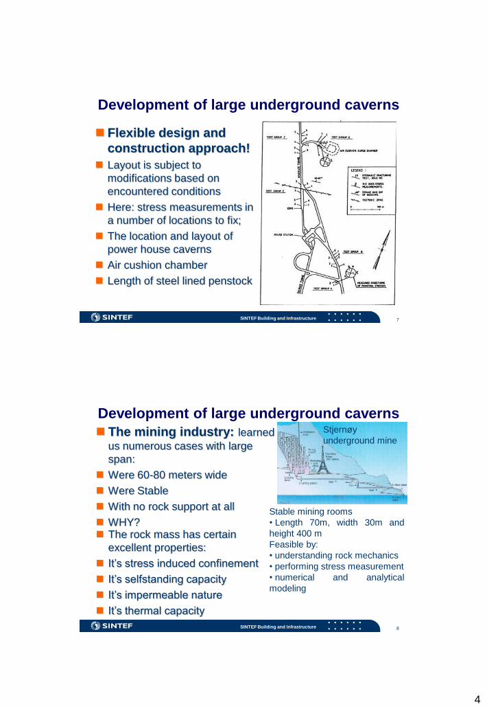
Development of large underground caverns
Flexible design and
construction approach!
Layout is subject to
modifications based on
encountered conditions
Here: stress measurements in
a number of locations to fix;
The location and layout of
power house caverns
Air cushion chamber
Length of steel lined penstock
SINTEF Building and Infrastructure 8
Development of large underground caverns
The mining industry: learned
us numerous cases with large
span:
Were 60-80 meters wide
Were Stable
With no rock support at all
WHY? The rock mass has certain
excellent properties:
It’s stress induced confinement
It’s selfstanding capacity
It’s impermeable nature
It’s thermal capacity
Stable mining rooms
• Length 70m, width 30m and
height 400 m
Feasible by:
• understanding rock mechanics
• performing stress measurement
• numerical and analytical
modeling
Stjernøy
underground mine

5
SINTEF Building and Infrastructure 9
Measuring in-situ stress
A diamond drill hole (76 mm outer diameter) is drilled to the desired
depth. Usually, this depth is 1,5 times the span of tunnel/ cavern.
The hole bottom is flattened with a special drill bit, and a concentric
hole with smaller diameter (36 mm o.d) is drilled approximately 30
cm further.
A measuring cell with strain gauges and data log unit is installed
with a special installing tool containing orienting device.
Compressed air is used to expand the cell in the hole, and the strain
gauges are fixed to the walls in the hole.
The cell is now ready to start measuring, and continously logging of
strain data is stored in the measuring cell. The installing tool is
removed and the cell is ready for overcoring.
The small hole is over cored by the larger diameter bit, thus stress
relieving the core. The corresponding strains are recorded by the
strain gauge rosettes. The core is recovered from the hole with a
special core catcher, and immediately after removal from for the
hole the recorded data is transferred to the computer. When the
elastic parameters are determined from biaxial- and laboratory test,
the stresses may be calculated.
SINTEF Building and Infrastructure 10
Arch effect in roof
Pillar capacity
Water curtain
pressure
Optimized geometry!
Area for 3D
Pilar stress
horizontallyPilar stress vertically
Measuring in-situ stress
In a virgin rock body

6
SINTEF Building and Infrastructure 11
Measuring in-situ stress
Increase the pressure at a speed of 0,1-0,5 MPa/sek
At critical pressure a crack is initiated and water flows into
the rock mass
Water supply is cut off
Re-pressurize
SINTEF Building and Infrastructure 12
Measuring in-situ stress
Measuring
hydraulic
fracturing and
jacking existing
cracks
Shut-in
pressure sets
equal to σ3

7
SINTEF Building and Infrastructure 13
Tunnel Engineering Handbook
By Bickel & Kuesel:
Knowledge of the in-situ
stresses is essential to the
sound, logical design of
rock reinforcement systems,
excavation procedures and
opening layouts, and to the
interpretation of expected
rock strength and
deformational properties.
How did this happen??
Lack of knowledge of the in-situ
stress?!
SINTEF Building and Infrastructure 14
Development of large underground caverns
Some guidelines on design: Geotechnical mapping focusing joints
and weak zones, geomechanical tests
In-situ stress measurements are required (often from surface/adjacent UG opening)
Work in the 3-D picture, pillars are subject to high stresses, corners & bends are released
Locate and align the cavern
Empirical and analytical design
Numerical modeling and analytical models to verify layout
Observation/monitoring in excavation

8
SINTEF Building and Infrastructure 15
A particular functional
requirement of certain
facilities!
To reduce the length of access
tunnels
Lead to:
Shallow locations, such as
Holmlia: width 25m, rock cover is
only 15m
Gjøvik: width 61m, rock cover
between 25 and 50m
Confinement, OR in-situ rock stress
How??
Knowledge of the in-situ
stress situation is crucial
SINTEF Building and Infrastructure 16
Construction of large underground caverns
Normally excavation is split into various sections:
Top heading
Benching
Each level must be mapped and sup--ported prior to going to lower level
Benching can be by vertical blast holes
Logistic is a challenge and do not believe that work is going on as smooth as on the figure
Knowing the stress conditions may allow a different sequence leaving a horisontal pilar to be done lastly
Observe the water
curtain holes above the
caverns, typical oil and
gas caverns to work in
saturated rock mass

9
SINTEF Building and Infrastructure
Construction of large underground caverns
Stability of caverns:
Visual inspections of exposed
rock, shotcrete and bolts
Measuring bolts
Extensometers (rod & tape),
convergence pins
The Gjøvik hall
was a complicated excavation
procedure with pilots and a
number of side stopping,
slashing, headings and
benches
SINTEF Building and Infrastructure 18
Construction of large underground caverns
”Unlined” Tunnelling!
Permanent rock support
consists of rock bolts and
shotcrete
Primary support is approved as
permanent on the condition that
it meets the material standard
Active design of support to fit
the encountered geological
conditions
Water control by groutingHydrocarbon storage at
Sture

10
SINTEF Building and Infrastructure 19
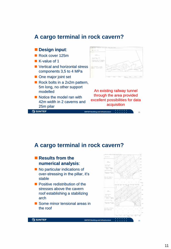
A cargo terminal in rock cavern?
A cargo terminal; is being planned in
Trondheim covering a huge surface area replacing the existing one.
Is there any other option?
We were looking at the possibility of locating the shunting area underground.
In large underground caverns! Of course.
SINTEF Building and Infrastructure 20
A cargo terminal in rock cavern?
Underground solutions:
One single cavern with a width of 42m
and length of 700m
Two parallel caverns, each 28m wide
and with a pillar of 25m width
EXIT
ENTRANCE
2 CAVERNS
SOLUTOION FOR
SHUNTING AREA
1 TUNNEL TRACK THROUGH THE SYSTEM 2500 M
11
SINTEF Building and Infrastructure 21
A cargo terminal in rock cavern?
Design input:
Rock cover 125m
K-value of 1
Vertical and horizontal stress
components 3,5 to 4 MPa
One major joint set
Rock bolts in a 2x2m pattern,
5m long, no other support
modelled
Notice the model ran with
42m width in 2 caverns and
25m pilar
An existing railway tunnel
through the area provided
excellent possibilities for data
acquisition
SINTEF Building and Infrastructure 22
A cargo terminal in rock cavern?
Results from the
numerical analysis:
No particular indications of
over-stressing in the pillar, it’s
stable
Positive redistribution of the
stresses above the cavern
roof establishing a stabilizing
arch
Some minor tensional areas in
the roof

12
SINTEF Building and Infrastructure 23
The worlds largest public rock cavernWhat made the Gjøvik hall
feasible?? Results from earlier projects
indicate presence of sufficient high horizontal stress
In situ stress measurements were done; σh=3-5MPa at a depth of 25-50m which is far more than the theoretical gravity approach (<1MPa)
Q-values of 30 (best=Good), 1 (lowest =Poor) and 12 (average=Good)
Numerical analysis indicated 5-10mm displacement
Rock support of the Gjøvik
hall constitutes: 6m fully
grouted 25mm grouted
rebar in 2,5x2,5m, every
fourth bolt is a 12m cable
bolt, and 100mm shotcrete
SINTEF Building and Infrastructure 24
The worlds largest public rock cavern A thorough monitoring
program was undertaken
Multipoint extensometers placed in
boreholes from surface (E) and
from holes drilled from cavern (S)
The maximum deflection was
measured to 7mm, stable trend 300
days after excavation
2D stress measurements were
done in the cavern roof
Compressive stress in the range of
2-5MPa (arch/confinement).
Measuring rock bolts showed minor
loading

13
SINTEF Building and Infrastructure 25
Some pros and cons of in-situ stressType of facility 1 3 K = hor/vert
Rock caverns Moderate to high level can
enable an optimised geometry,
too high may lead to stability
problems
Low level may produce a too
small arch building in the
roof/lack of confinement thus
instability.
K= 1-2 is OK.
K> 3 is not OK.
K< 0,5 is not OK.
Pressurised
tunnels/caverns
Minor influence, high level may
give stability problems.
Minor principal stress
component must be higher
than the water pressure (or
the pressure from any other
confined material) as an
ultimate requirement.
No particular
requirement.
Facilities with
particular
requirements to
tightness
Moderate to high level can
provide good confinement and
stability and improved
tightness.
Critical low level gives
poor safety against leakage.
Grout design press. < 3
Storage pressure < 3
No particular
requirement.
Transport-tunnels Moderate to high level is good
for the confinement and
stability. Too high stresses may
give stability-problems,
spalling.
No particular requirements,
but low stress might lead to
lack of confinement and
instability.
K appr. 1 is OK.
SINTEF Building and Infrastructure 26
Conclusions
Large underground caverns
have been used in Norway
for several purposes
Majority have typical
dimensions 15-25m width
Unlined caverns, supported
by rock bolts and sprayed
concrete
In-situ stresses are utilized
to obtain confinement
Field testing is needed
Underground, presence of
in-situ rock stresses would
normally be an asset