Embed Size (px)
Citation preview

PageContents 5Selector Guide 9Index of Types 17
General Technical Information 19
Data Sheets 41
Mounting Instructions 161Quality 167Environmental Protection, Climatic Conditions 173, 175
Taping and Packing 177Symbols and Terms 183Subject Index 185

Siemens Matsushita ComponentsCOMPONENTS
+S M
SCS – dependable, fast and competent
EMI suppression capacitors
Play it safe
Whether video recorder, television,refrigerator or toaster – our EMI sup-pression capacitors do a grand job inevery possible kind of entertainmentand consumer electronics appliance.They’ve also proven their worth inswitch-mode power supplies for PCs.No wonder, because the advantagesof film technology are there to beseen: low cost, no risk of failurethrough damp, and optimum self-
healing capability. The result – lessdestruction of equipment and ensuingfires. Plus the line is safeguardedagainst surges. In this way our ca-pacitors satisfy the user’s need forsafety, and the new EMC standardstoo of course.

PTC Thermistors

Creatingnewlinks
As of now you can tie upwith Passive Componentsand Electron Tubes Groupplus Siemens Matsushita Components on the Internet. On our home page under
http://www.siemens.de/pr/index.htm
you’ll find the latest short form cata-logs, data books, technical articlesand more subjects too. You can viewthe documents on-line, or downloadthem to your PC. The “Installation“menu item tells you how to do it.Thanks to the integrated search function, you only have to enter keyterms to go straight to the right document. And of course, you canget in touch with us direct by E mailat any time.
Wo
rld
Wide Web Ser
vic
e
SCS – dependable, fast and competent
SCS on the Internet

Contents
Contents
Selector guide 9
Index of types 17
General technical information 19
1 Definition 19
2 Structure and function 19
3 Manufacture 19
4 Characteristics 20
4.1 Unloaded PTC thermistors 204.1.1 Temperature dependence of resistance 204.1.2 Rated resistance RN 214.1.3 Minimum resistance Rmin 214.1.4 Reference resistance RRef at reference temperature TRef 214.1.5 Resistance RPTC at temperature TPTC 224.1.6 Temperature coefficient α 224.1.7 Nominal threshold temperature TNAT 224.2 Electrically loaded PTC thermistors 224.2.1 Surface temperature Tsurf 234.2.2 Current/voltage characteristic 234.2.3 Trip current IK 234.2.4 Rated current IN and switching current IS 244.2.5 Residual current Ir 244.3 Electrical maximum ratings Imax, ISmax 244.3.1 Maximum operating voltage Vmax, rated voltage VN,
maximum measuring voltage VMeas,max and breakdown voltage VD 244.3.2 Switching time tS 244.3.3 Insulation test voltage Vis 254.3.4 Pulse strength VP 254.4 Thermal characteristics 254.4.1 Thermal cooling time constant τc 254.4.2 Thermal threshold time ta 254.4.3 Response time tR 254.4.4 Settling time tE 26
5 Notes on operating mode 26
5.1 Voltage dependence of resistance 265.2 Frequency dependence of resistance 275.3 Influence of heat dissipation on PTC temperature 285.4 Influence of ambient temperature on the I/V characteristic 28
6 Application notes 29
6.1 PTC thermistors for overload protection 296.1.1 Operating states of a PTC thermistor for overload protection 306.1.2 Considerations on trip current 30
Siemens Matsushita Components 5

Contents
6.1.3 Switching time versus switching current 326.1.4 Selection criteria 336.1.5 Circuit configuration 346.2 PTC thermistors for time delay 356.3 PTC thermistors for motor starting 376.4 PTC thermistors for picture tube degaussing 376.5 PTC thermistors as level sensors 386.6 PTC thermistors for measurement and control, temperature sensors 396.7 PTC thermistors as heating elements 40
Data sheets 41
Overload protection 41
Disks 41Rods 76Telecom disks 78SMDs 80
Degaussing 88
Switching 91
Motor starting 100
Motor and machine protection 102
Level sensors 126
Measurement and control 132
Disks 132Probe assemblies 142SMDs 148
Heating elements and thermostats 150
Mounting instructions 161
1 Soldering 161
1.1 Leaded PTC thermistors 1611.2 Leadless PTC thermistors 1611.3 SMD PTC thermistors 1611.3.1 Wettability test 1611.3.2 Soldering heat resistance test 1621.3.3 Recommended soldering temperature profiles 1621.3.4 Notes 164
2 Conductive adhesion 164
3 Clamp contacting 164
6 Siemens Matsushita Components

Contents
4 Robustness of terminations 164
5 Sealing and potting 165
6 Cleaning 165
7 Storage 165
Quality 167
1 Manufacturing process and quality assurance 167
2 General 168
3 Sequence of quality assurance measures 168
3.1 Incoming inspection 1683.2 Process assurance 1683.3 Product assurance 1683.4 Final inspection 168
4 Delivery quality 168
5 Sampling inspection 169
6 Classification of defects 169
7 AQL values 169
8 Incoming inspection by the customer 170
9 Reliability 171
10 Identification and retraceability 171
11 Supplementary information 172
Environmental protection measures 173
Climatic conditions 175
1 Reliability data 175
2 Operating temperature range 175
Taping and packing 177
1 Taping of SMD thermistors 177
2 Taping of radial-lead PTC thermistors 179
3 Packing codes 181
Symbols and terms 183
Subject index 185
Siemens Matsushita Components 7

SCS – dependable, fast and competent
European technology center forceramic components
Siemens Matsushita ComponentsCOMPONENTS
+S M
There when youneed usThis is an organization that’s provenits worth. Because it stands formore customer proximity and thusbetter service. Here you get infor-mation straight from the source,implementation of the latest tech-nologies and products that matchthe market. Concentration of resources means that designengineers and production engineersare working side by side. And SCSwarehousing directly at the plantensures fastest possible delivery.

Selector G
uideSelector Guide
PTC thermistors for overload protection
Type VmaxV
INmA
ISmA
TRef°C
RNΩ
Page
B599*5(C 9*5)
20 150 …2900
300 …5700
160 0,2 …13 41
B599*5(C 9*5)
30 120 …2500
240 …5000
120 0,2 …13 44
B599*0(C 9*0)
54 55 …1150
120 …2370
160 0,9 …55 47
B599*0(C 9*0)
80 30 …530
60 …1100
80 0,9 …55 50
B599*0(C 9*0)
80 50 …1000
100 …2000
120 0,9 …55 53
B598*0(C 8*0)
160 35 …800
70 …1600
160 2,6 …150 56
B598*0(C 8*0)
265 15 …350
40 …710
80 2,6 …150 59
B598*1(C 8*1)
265 30 …730
65 …1450
135 2,6 …150 62
B598**(C 8**)
265 …550
12 …650
24 …1300
120 2,6 …1500 65
B597**(B 7**)
420 …1000
8 …123
17 …245
110 …120
25 …7500 71
Siemens Matsushita Components 9

Selector Guide
B5940*(B 40*)
500 …550
2,5 …4
6,5 …12
60 3500 …5500 76
Telecom PTC thermistors
B5902*(S 102*)
245 55 …200
110 …400
120 10 …70 78
B59707(A 1707)
80 45 90 120 12580
B59607(A 1607)
80 65 130 120 5580
B59*01(P 1*01)
30 90 …310
185 …640
85; 130 3,1 …13 82
B59*15(P 1*15)
80 40 …150
85 …310
80; 120 16 …55 85
PTC thermistors for overload protection
Type VmaxV
INmA
ISmA
TRef°C
RNΩ
Page
10 Siemens Matsushita Components
Selector Guide
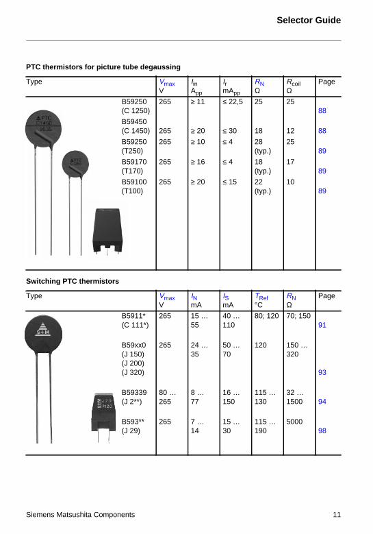
PTC thermistors for picture tube degaussing
Type VmaxV
IinApp
IrmApp
RNΩ
RcoilΩ
Page
B59250(C 1250)
265 ≥ 11 ≤ 22,5 25 2588
B59450(C 1450) 265 ≥ 20 ≤ 30 18 12 88
B59250(T250)
265 ≥ 10 ≤ 4 28(typ.)
2589
B59170(T170)
265 ≥ 16 ≤ 4 18(typ.)
1789
B59100(T100)
265 ≥ 20 ≤ 15 22(typ.)
1089
Switching PTC thermistors
Type VmaxV
INmA
ISmA
TRef°C
RNΩ
Page
B5911*(C 111*)
265 15 …55
40 …110
80; 120 70; 15091
B59xx0(J 150)(J 200)(J 320)
265 24 …35
50 …70
120 150 …320
93
B59339(J 2**)
80 …265
8 …77
16 …150
115 …130
32 …1500 94
B593**(J 29)
265 7 …14
15 …30
115 …190
500098
Siemens Matsushita Components 11

Selector Guide
PTC thermistors for motor starting
Type VmaxV
ImaxmA
TRef°C
RNΩ
Page
B5919*; B5921*(A 19*, A 21*,J 19*, J 21*)
175 …400
4 …8
120; 135 4,7 …33 100
PTC thermistors for motor and machine protection
Type VmaxV
TNAT°C
RNΩ
Page
B59100(M 1100)
25 60 … 190 ≤ 100102
B59135(M 135)
30 60 … 180 ≤ 250106
B59155(M 155)
30 60 … 180 ≤ 100110
B59300(M 1300)
25 60 … 190 ≤ 300114
B59335(M 335)
30 60 … 180 ≤ 750118
B59355(M 355)
30 60 … 180 ≤ 300122
12 Siemens Matsushita Components
Selector Guide
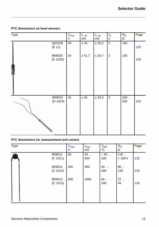
PTC thermistors as level sensors
Type VmaxV
Ir, oilmA
Ir, airmA
tSs
RNΩ
Page
Q63100(E 11)
24 ≥ 45 ≤ 35,5 2 140126
B59020(E 1020)
24 ≥ 41,7 ≤ 26,7 2 135128
24 ≥ 45 ≤ 33,5 2 100 …200 130
PTC thermistors for measurement and control
Type VmaxV
ImaxmA
TRef°C
RNΩ
Page
B59011(C 1011)
30 45 …430
– 30 …180
110 …> 100 k 132
B59012(C 1012)
265 300 40 …180
80 …130 134
B59013(C 1013)
265 1000 40 …180
27 …46 136
B59010(D 1010)
Siemens Matsushita Components 13

Selector Guide
PTC thermistors for measurement and control
Type VmaxV
TNAT°C
RNΩ
Page
B59008(C 8)
30 60 …180
≤ 250138
B59100(C 100)
30 60 …180
≤ 100140
Type VmaxV
ImaxmA
TRef°C
RNΩ
Page
B59401(D 401)
20 175 …270
40 …120
80 …130 142
14 Siemens Matsushita Components

Selector Guide
B59801(D 801)
30 60 …160
≤ 100144
B59901(D 901)
30 60 …140
≤ 100146
B59701(A 1701)
25 90 …130
≤ 1000148
PTC thermistors for measurement and control
Type VmaxV
TNAT°C
RNΩ
Page
Siemens Matsushita Components 15

Selector Guide
PTC thermistors as heating elements and thermostats
Type VNV
TRef°C
RNΩ
Page
B59060(A 60)
12 0 … 280 9 … ≥ 320150
B59053(A 53)
230 50 … 270 4200 … 6000152
B59066(A 66)
220 50 … 270 1200; 1700154
B59042(R 1042)
12 40 … 280 3,2 … 12,8156
B59102(R 102)
230 50 … 290 700 … 1300158
16 Siemens Matsushita Components

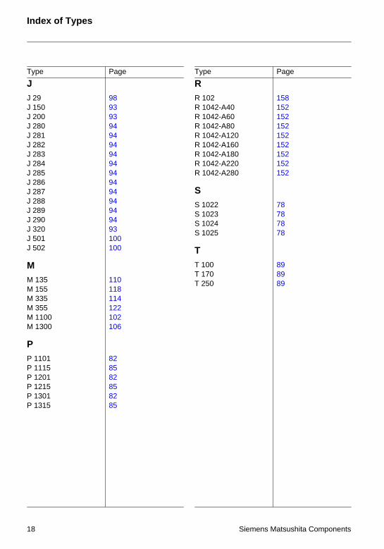
Type Page Type Page
Index of TypesIndex of T
ypes
AA 53 154A 60 150A 66 156A 192 100A 196 100A 501 100A 502 100A 1607 80A 1701 148A 1707 80
BB 404 76B 406 76B 750 71B 751 71B 752 71B 753 71B 754 71B 755 71B 758 71B 770 71B 771 71B 772 71B 773 71B 774 71
CC 8 138C 100 140C 810 56, 59, 66C 811 62C 830 56, 59, 66C 831 62C 840 56, 59, 66C 841 62C 850 56, 59, 66C 851 62C 860 56, 59, 66C 861 62C 870 56, 59, 66C 871 62C 872 66
C 873 66C 874 66C 875 66C 880 56, 59, 66C 881 62C 883 66C 884 66C 885 66C 886 66C 890 56, 59, 66C 891 62C 910 47, 50, 53C 915 41, 44C 930 47, 50, 53C 935 41, 44C 940 47, 50, 53C 945 41, 44C 950 47, 50, 53C 955 41, 44C 960 47, 50, 53C 965 41, 44C 970 47, 50, 53C 975 41, 44C 980 47, 50, 53C 985 41, 44C 990 47, 50, 53C 995 41, 44C 1011 132C 1012 134C 1013 136C 1118 91C 1119 91C 1250 88C 1450 88
DD 401 142D 801 144D 901 146D 1010 130
EE 11 126E 1020 128
Siemens Matsushita Components 17
Type Page Type Page
Index of Types
JJ 29 98J 150 93J 200 93J 280 94J 281 94J 282 94J 283 94J 284 94J 285 94J 286 94J 287 94J 288 94J 289 94J 290 94J 320 93J 501 100J 502 100
MM 135 110M 155 118M 335 114M 355 122M 1100 102M 1300 106
PP 1101 82P 1115 85P 1201 82P 1215 85P 1301 82P 1315 85
RR 102 158R 1042-A40 152R 1042-A60 152R 1042-A80 152R 1042-A120 152R 1042-A160 152R 1042-A180 152R 1042-A220 152R 1042-A280 152
SS 1022 78S 1023 78S 1024 78S 1025 78
TT 100 89T 170 89T 250 89
18 Siemens Matsushita Components

General T
echnical Information
General Technical Information
1 Definition
A PTC thermistor is a thermally sensitive semiconductor resistor. Its resistance value rises sharplywith increasing temperature after a defined temperature (reference temperature) has beenexceeded.
The very high positive temperature coefficient (PTC) has given the PTC thermistor its name.
Applicable standards are CECC 44000, EN 144 000, IEC 738-1 and DIN 44 080.
2 Structure and function
PTC thermistors are made of doped polycrystalline ceramic on the basis of barium titanate. Gener-ally, ceramic is known as a good insulating material with a high resistance. Semiconduction andthus a low resistance are achieved by doping the ceramic with materials of a higher valency thanthat of the crystal lattice. Part of the barium and titanate ions in the crystal lattice is replaced withions of higher valencies to obtain a specified number of free electrons which make the ceramic con-ductive.
The material structure is composed of many individual crystallites (figure 1) which are responsiblefor the PTC thermistor effect, i.e. the abrupt rise in resistance. At the edge of these monocrystallites,the socalled grain boundaries, potential barriers are formed. They prevent free electrons from dif-fusing into adjacent areas. Thus a high resistance results. However, this effect is neutralized at lowtemperatures. High dielectric constants and sudden polarization at the grain boundaries prevent theformation of potential barriers at low temperatures enabling a smooth flow of free electrons.
Above the Curie temperature dielectric constant and polarization decline so far that there is a stronggrowth of the potential barriers and hence of resistance. Beyond the range of the positivetemperature coefficient α the number of free charge carriers is increased by thermal activation. Theresistance then decreases and exhibits a negative temperature characteristic (NTC) typical of semi-conductors.
3 Manufacture
Mixtures of barium carbonate, titanium oxide and other materials whose composition produces thedesired electrical and thermal characteristics are ground, mixed and compressed into disks, wash-ers, rods, slabs or tubular shapes depending on the application.
Figure 1
Schematic representation of the polycrystallinestructure of a PTC thermistor.
The PTC resistance RPTC is composed of indi-vidual crystal and grain boundary resistances.The grain boundary resistance is strongly tem-perature-dependent.
RPTC = Rgrain + Rgrain boundaryRgrain boundary = f (T )
Siemens Matsushita Components 19

General Technical Information
These blank bodies are then sintered, preferably at temperatures below 1400 °C. Afterwards, theyare carefully contacted, provided with connection elements depending on the version and finallycoated or encased.
A flow chart in the quality section of this book (see page 167) shows the individual processing stepsin detail. The chart also illustrates the extensive quality assurance measures taken during manu-facture to guarantee the constantly high quality level of our thermistors.
4 Characteristics
A current flowing through a thermistor may cause sufficient heating to raise the thermistor’s tempera-ture above the ambient. As the effects of self-heating are not always negligible, a distinction has to bemade between the characteristics of an electrically loaded thermistor and those of an unloaded ther-mistor. The properties of an unloaded thermistor are also termed “zero-power characteristics”.
4.1 Unloaded PTC thermistors
4.1.1 Temperature dependence of resistance
The zero-power resistance value RT is the resistance value measured at a given temperature T withthe electrical load kept so small that there is no noticeable change in the resistance value if the loadis further reduced.
For test voltages, please refer to the individual types (mostly ≤ 1,5 V).
Figure 2 shows the typical dependence of the zero-power resistance on temperature. Because ofthe abrupt rise in resistance (the resistance value increases by several powers of ten), theresistance value is plotted on a logarithmic scale (ordinate) against a linear temperature scale(abscissa).
Figure 2
Typical resistance/temperature characteristicRPTC = f (TPTC)
RN Rated PTC resistance(resistance value at TN 25 °C)
Rmin Minimum resistance(resistance value at TRmin)
TRmin Temperature at Rmin(α becomes positive)
RRef Reference resistance(resistance value at TRef)
TRef Reference temperature(resistance rises sharply)
RPTC Resistance in the steep region
TPTC Temperature for which RPTCis guaranteed
∧
TPT0
316-
H
20 Siemens Matsushita Components

General Technical Information
The tolerances in figure 3 are provided for PTC thermistors which must have an exactly definedzero-power resistance curve.
4.1.2 Rated resistance RN
The rated resistance RN is the resistance value at temperature TN. PTC thermistors are classifiedaccording to this resistance value. The temperature TN is 25 °C, unless otherwise specified.
4.1.3 Minimum resistance Rmin
The beginning of the temperature range with a positive temperature coefficient is specified by thetemperature TRmin. The value of the PTC resistance at this temperature is designated as Rmin. Thisis the lowest zero-power resistance value which the PTC thermistor is able to assume. Rmin is oftengiven as a calculable magnitude without stating the corresponding temperature. The Rmin valuesspecified in this data book allow for the R tolerance range of the individual types and represent thelower limit.
4.1.4 Reference resistance RRef at reference temperature TRef
The start of the steep rise in resistance, marked by the reference temperature TRef, which corre-sponds approximately to the ferroelectric Curie point, is significant for the application. For the indi-vidual types of PTC thermistors it is defined as the temperature at which the zero-power resistanceis equal to the value RRef = 2 · Rmin.
Figure 3
Variation of PTC resistanceRPTC = f (TPTC) (tolerance diagram)
RN Rated resistanceResistance value atTN withspecified tolerance ± ∆RN
Rmin Minimum resistance valueat TRmin
RRef Resistance value at TRef
R (TRef – ∆TRef)Resistance value atTRef – ∆TRef
R (TRef + ∆TRef)Resistance value atTRef + ∆TRef
TRef ± ∆TRef Reference temperaturewith ± tolerances
RPTCmin Minimum resistance valueat TPTC
Siemens Matsushita Components 21
General Technical Information
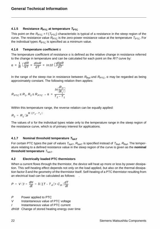
4.1.5 Resistance RPTC at temperature TPTC
This point on the RPTC = f (TPTC) characteristic is typical of a resistance in the steep region of thecurve. The resistance value RPTC is the zero-power resistance value at the temperature TPTC. Forthe individual types RPTC is specified as a minimum value.
4.1.6 Temperature coefficient αThe temperature coefficient of resistance α is defined as the relative change in resistance referredto the change in temperature and can be calculated for each point on the R/T curve by:
In the range of the steep rise in resistance between RRef und RPTC, α may be regarded as beingapproximately constant. The following relation then applies:
Within this temperature range, the reverse relation can be equally applied:
The values of α for the individual types relate only to the temperature range in the steep region ofthe resistance curve, which is of primary interest for applications.
4.1.7 Nominal threshold temperature TNAT
For certain PTC types the pair of values TNAT, RNAT is specified instead of TRef, RRef. The temper-ature relating to a defined resistance value in the steep region of the curve is given as the nominalthreshold temperature TNAT.
4.2 Electrically loaded PTC thermistors
When a current flows through the thermistor, the device will heat up more or less by power dissipa-tion. This self-heating effect depends not only on the load applied, but also on the thermal dissipa-tion factor δ and the geometry of the thermistor itself. Self-heating of a PTC thermistor resulting froman electrical load can be calculated as follows: .
P Power applied to PTCV Instantaneous value of PTC voltageI Instantaneous value of PTC currentdH/dt Change of stored heating energy over time
α1R----
dRdT--------⋅ dlnR
dT-------------- In10
dlgRdT
--------------⋅= = =
RPTC R1 R2 RPTC α→≤,≤ln
R2
R1-------
T 2 T 1–--------------------=
R2 R1 eα T 2 T 1–( )⋅
⋅=
P V I Hdtd
--------=⋅ δ T T A–( ) CthTdtd
-------⋅+⋅= =
22 Siemens Matsushita Components

General Technical Information
δ Dissipation factor of PTCT Instantaneous temperature of PTCTA Ambient temperatureCth Heat capacity of PTCdT/dt Change of temperature over time
4.2.1 Surface temperature Tsurf
Tsurf is the temperature reached on the thermistor’s surface when it has been operated at specifiedrated voltage and in a state of thermal equilibrium with the ambient for a prolonged period of time.The specifications in the data sheet section refer to an ambient temperature of 25 °C.
4.2.2 Current/voltage characteristic
The properties of electrically loaded PTC thermistors (in self-heated mode) are better described bythe I/V characteristic than by the R/T curve. It illustrates the relationship between voltage and cur-rent in a thermally steady state in still air at 25 °C, unless another temperature is specified.
4.2.3 Trip current IKThe trip current IK is the current flowing through the thermistor at an applied voltage VK. It is thecurrent at which the electrical power consumed is high enough to raise the temperature of the de-vice above the reference temperature TRef.
Figure 4
I/V characteristic of a PTC thermistor
IK Trip current at applied voltage VK(start of current limitation)
Ir Residual current at applied voltage Vmax(current is balanced)
Vmax Maximum operating voltage
VN Rated voltage (VN < Vmax)
VD Breakdown voltage (VD > Vmax)
Siemens Matsushita Components 23

General Technical Information
4.2.4 Rated current IN and switching current ISThe tolerance range of the trip current depends on the mechanical and electrical component toler-ances. Knowing the tolerance limits is decisive in selecting the most suitable PTC thermistor. Inpractical use it is important to know at which current the PTC thermistor is guaranteed not to tripand at which currents the thermistor will reliably go into high-resistance mode. For this reason wedo not specifiy the trip current in general, but its lower limit IN and its upper limit IS.
Rated current IN: At currents ≤ IN the PTC thermistor reliably remains in low-resistance mode.
Switching current IS: At currents ≥ IS the PTC thermistor reliably goes into high-resistance mode.
The currents specified in the data sheets refer to TA = 25 °C.
4.2.5 Residual current IrThe residual current Ir is the current developed at applied maximum operating voltage Vmax and atthermal equilibrium (steady-state operation).
4.3 Electrical maximum ratings Imax, ISmax
In electrically loaded PTC thermistors electrical power is converted into heat. The high loads gen-erated for a short period of time during the heating phase (the PTC thermistor is in low-resistancemode when the operating voltage is applied) are limited by the specification of maximum permissi-ble currents Imax, ISmax and voltages Vmax in the data sheet section.
The number of heating processes is also an important criterion. The permissible number of switch-ing cycles not affecting function or service life is given in the data sheets and applies to operationat specified maximum loads.
4.3.1 Maximum operating voltage Vmax, rated voltage VN,maximum measuring voltage VMeas,max and breakdown voltage VD
The maximum operating voltage Vmax is the highest voltage which may be continuously appliedto the thermistor at the ambient temperatures specified in the data sheets (still air, steady-state,high-resistance mode). For types without Vmax specification (e.g. heating elements) the permissiblemaximum voltage is VN + 15 %.
The rated voltage VN is the supply voltage lying below Vmax.
The maximum measuring voltage VMeas,max is the highest voltage that may be applied to the ther-mistor for measuring purposes.
The breakdown voltage VD is a measure for the thermistor’s maximum voltage handling capability.Beyond VD the PTC thermistor no longer exhibits its characteristic properties.
Switching current, operating current or minimum series resistances are specified to ensure that thePTC thermistor will not be overloaded.
4.3.2 Switching time tS
If Vmax and Imax are known, it is possible to describe the PTC thermistor’s switch-off behavior interms of switching time tS. This is the time it takes at applied voltage for the current passing throughthe PTC to be reduced to half of its initial value. The tS values apply to TA = 25 °C.
24 Siemens Matsushita Components

General Technical Information
4.3.3 Insulation test voltage Vis
The insulation test voltage Vis is applied between the body of the thermistor and its encapsulationfor a test period of 5 seconds.
4.3.4 Pulse strength VP
The pulse strength is specified on the basis of the standardized voltage pulses shown in figure 5.Voltage transients within the stated number of cycles and amplitude will not damage the compo-nent.
4.4 Thermal characteristics
4.4.1 Thermal cooling time constant τc
The thermal cooling time constant refers to the time necessary for an unloaded thermistor to varyits temperature by 63,2 % of the difference between its mean temperature and the ambient temper-ature.
Equation for temperature change: T(t2) = T(t1) ± 0,0632 (T(t1) – TA) with t2 – t1 = τth
4.4.2 Thermal threshold time ta
The thermal threshold time ta is the time an unloaded PTC thermistor needs to increase its temper-ature from starting temperature (25 °C) to reference temperature TRef or nominal threshold temper-ature TNAT (resistance 1330 Ω) by external heating.
4.4.3 Response time tR
The response time tR is the time a PTC thermistor requires to recognize the change of power dis-sipation resulting from a change of the surrounding medium at applied voltage. After this period oftime the residual currents assigned to the individual media become effective in the device.
Figure 5
Pulse definition as per IEC 60-2VDE 0433
Rise time: tr = 8 µs
Decay time to half value: td = 20 µs
Peak voltage value: refer toindividual type
Siemens Matsushita Components 25

General Technical Information
4.4.4 Settling time tE
The settling time tE refers to the time the PTC thermistor needs to reach operating condition afterthe operating voltage has been applied (only for level sensors).
5 Notes on operating mode
5.1 Voltage dependence of resistance
The R/T characteristic shows the relationship between resistance and temperature at zero power,i.e. when self-heating of the PTC thermistor is negligible.
The resistance of the PTC thermistor is composed of the grain resistance and the grain boundarytransition resistance. Particularly in the hot state, the strong potential barriers are determining re-sistance. Higher voltages applied to the PTC thermistor therefore drop primarily at the grain bound-aries with the result that the high field strengths dominating here produce a break-up of the potentialbarriers and thus a lower resistance. The stronger the potential barriers are, the greater is the influ-ence of this “varistor effect” on resistance. Below the reference temperature, where the junctionsare not so marked, most of the applied voltage is absorbed by the grain resistance. Thus the fieldstrength at the grain boundaries decreases and the varistor effect is quite weak.
Figure 6 shows the typical dependence of resistance on field strength. It can be seen that the dif-ference in resistance is largest between R(E1), R(E2) and R(E3) at temperature Tmax and thus inthe region of maximum resistance. (Note: RPTC is plotted on a logarithmic scale.)
Figure 6
Influence of field strength E on theR/T characteristic (varistor effect)αR1 > αR2 > αR3
26 Siemens Matsushita Components

General Technical Information
Due to this dependence on the positive temperature coefficient of the field strength, operation onhigh supply voltages is only possible with PTC thermistors that have been designed for this purposeby means of appropriate technological (grain size) and constructional (device thickness) measures.
The R/T curves in the data sheet section are zero-power characteristics.
5.2 Frequency dependence of resistance
Due to the structure of the PTC thermistor material the PTC thermistor on ac voltage is not a purelyohmic resistor. It also acts as a capacitive resistor because of the grain boundary junctions (seeequivalent circuit diagram, figure 7).
The impedance measured at ac voltage decreases with increasing frequency. The dependence ofthe PTC resistance on temperature at different frequencies is shown in figure 8. So the use of thePTC thermistor in the AF and RF ranges is not possible, meaning that applications are restricted todc and line frequency operation.
Figure 7
Equivalent circuit diagram of aPTC thermistor on ac voltage
Rgrain boundary
Cgrain boundary
Rgrain
Figure 8
Influence of frequency on theR/T characteristic
Siemens Matsushita Components 27

General Technical Information
5.3 Influence of heat dissipation on PTC temperature
Figure 9a shows the electrical power Pel converted in a PTC thermistor as a function of its temper-ature. At a given operating voltage an operating point is established in the PTC depending on theambient temperature and thermal conduction from the thermistor to the environment.
The PTC thermistor heats up to an operating temperature above the reference temperature, for ex-ample (operating point A1 in Figure 9a). If the ambient temperature rises or the heat transfer to theenvironment decreases, the heat generated in the PTC thermistor can no longer be dissipated sothat the PTC will increase its temperature. Its operating point moves down the curve, e.g. to A2,causing a considerable reduction in current.
This limiting effect is maintained as long as Tmax is not exceeded. An increase in temperature be-yond Tmax would lead to the destruction of the PTC thermistor at a given operating voltage.
5.4 Influence of ambient temperature on the I/V characteristic
Figure 9b shows two I/V characteristics of one and the same PTC thermistor for two different am-bient temperatures T1 and T2, with T1 < T2. At the higher temperature the PTC thermistor has ahigher resistance value although the conditions are otherwise the same. Therefore, it carries lesscurrent. The curve for T2 is thus below that for T1. The breakdown voltage, too, depends on theambient temperature. If the latter is higher, the PTC thermistor reaches the critical temperaturewhere breakdown occurs on lower power or operating voltage. VD2 is therefore lower than VD1.
Figure 9a
Electrical power Pel in a PTC thermistorversus PTC temperature
Figure 9b
Influence of the ambient temperature onthe I/V characteristic
28 Siemens Matsushita Components

General Technical Information
6 Application notes
As to their possibilities of application, PTC thermistors can be divided in the following manner:
a) by function
b) by application
6.1 PTC thermistors for overload protection
Ceramic PTC thermistors are used instead of conventional fuses to protect loads such as motors,transformers, etc. or electronic circuits (line card) against overload. They not only respond to inad-missibly high currents, but also if a preset temperature limit is exceeded. Thermistor fuses limit thepower dissipation of the overall circuit by increasing their resistance and thus reducing the currentto a harmless residual value. In contrast to conventional fuses, they do not have to be replaced afterelimination of the fault, but resume their protective function immediately after a short cooling-downtime.
As opposed to PTC thermistors made of plastic materials, ceramic PTCs always return to their initialresistance value, even after frequent heating/cooling cycles.
Power PTC thermistors Sensors
Fuse Short-circuit andoverload protection
Temperature Overtemperature protectionMeasurement and control
Switch Motor startDegaussingTime delay
Limit temperatureMotor protectionOvertemperature protection
Heater Small heatersThermostats
Level sensor Limit indicators
Directly heated PTC thermistor
Heat is generated in thePTC thermistor
Power PTC thermistors
Applications where the electrical resistanceis primarily determined by the current passing
through the thermistor.
Indirectly heated PTC thermistor
Heat is supplied from outside
Temperature sensors
Applications where the electrical resistanceis primarily determined by the temperature of the
medium surrounding the thermistor.
Siemens Matsushita Components 29

General Technical Information
6.1.1 Operating states of a PTC thermistor for overload protection
Figure 11 illustrates the two operating states of a PTC fuse. In rated operation of the load the PTCresistance remains low (operating point A1). Upon overloading or shorting the load, however, thepower consumption in the PTC thermistor increases so much that it heats up and reduces the cur-rent flow to the load to an admissible low level (operating point A2). Most of the voltage then liesacross the PTC thermistor. The remaining current is sufficient to keep the PTC in high-resistancemode ensuring protection until the cause of the overload has been eliminated.
6.1.2 Considerations on trip current
An essential parameter for the function and selection of a PTC thermistor fuse is the trip current.This is the current at which the applied electrical power heats up the PTC thermistor to such an
Figure 10
PTC thermistor fuse connectedin series with the load
Figure 11
Operating states of a PTC thermistorfor overload protection
a Rated operation
b Overload operation
30 Siemens Matsushita Components

General Technical Information
extent that the supply of current is limited and the protective function is triggered. The trip current ismainly a function of
– PTC dimensions,– PTC temperature,– PTC resistance,– heat dissipation.
To be able to heat a PTC thermistor above its reference temperature, a minimum power (trip power)is necessary for given dimensions. A certain trip current is then established at a specified PTC re-sistance. The user has to take into account the tolerance of the trip current: lower limit = rated cur-rent, upper limit = minimum switching current.
Very often high trip currents are required. Higher trip currents with unchanged resistance are ob-tained through larger thermistor dimensions (see figure 12) or by raising the reference temperature.Favorable conditions for high trip currents can be achieved by making the best possible use of thecooling effect of the environment. The manufacturer contributes to good heat dissipation by produc-ing the thermistors with large surfaces and making them as thin as possible. The user can enhancethe heat dissipation effect by further measures (e.g. cooling fins) so that protective ratings of morethan 200 W per component can be achieved.
Another mechanism for controlling the trip current is the PTC resistance itself. To keep the spreadof the trip current as small as possible, PTC thermistor fuses are only produced in narrow resistanceranges. In practice this leads to PTC types with tolerances of 25 % and tighter so that the protectivefunction is also possible in applications with only slight differences in current between rated opera-tion and overload.
Another quantity affecting the trip current is the ambient temperature at which the PTC thermistoris operated. Figure 13 illustrates this relationship. An increase in ambient temperature means that
Figure 12
Influence of the PTC volume V on thetrip current at given resistance RPTC
(Vel: applied voltage)
Siemens Matsushita Components 31

General Technical Information
the PTC thermistor reaches the temperature causing it to trip with much less power consumption.A cooler environment has the opposite effect, i.e. power consumption and trip current rise.
6.1.3 Switching time versus switching current
The dynamic heating behavior of the PTC thermistor is determined by the specific heat capacity ofthe titanate material, which is approx. 3 Ws/cm3. At short switching times – being less than 5 sec-onds with commonly used overcurrent protection devices – heat dissipation through the surface andlead wires is virtually negligible: almost the entire electrical dissipation is consumed to heat up theceramic material, to increase the temperature above the reference temperature and thus to producea stable operating point on the R/T characteristic. When dissipation increases with rising differencebetween device temperature and ambient, only a small amount of excess energy remains for heat-ing the component and the result are the switching time curves as a function of switching currentshown in figure 14.
S + M Components offers a wide selection of PTC thermistors for overload protection from smallvoltages of 20 V and rated currents of 2,9 A through line voltage to high voltages of 1000 V and8 mA rated current. Many years of volume production and positive experience gained with the long-term features of overload protection components in practice have verified the particularly highsafety and reliability of these ceramic PTC thermistors.
Figure 13
Standardized trip current IK versusambient temperature TA (measuredin still air)
Parameter: TRef 1 <TRef 2 < TRef 3.
32 Siemens Matsushita Components

General Technical Information
6.1.4 Selection criteria
In designing a circuit, the following considerations should be borne in mind when selecting a PTCthermistor.
Maximum voltage
During normal operation only a small part of the overall voltage is applied to an overload protectionPTC thermistor in series with a load. When it responds, i.e. when it goes high-resistance, it has tohandle virtually the entire supply voltage. For this reason the thermistor’s maximum operating volt-age Vmax should be chosen sufficiently high. Possible supply voltage fluctuations should also beallowed for.
Rated current and switching current
The next thing is to find a PTC thermistor with sufficiently high rated current (that current at whichthe thermistor will under no circumstances turn off) within the suitable voltage class. To ensure re-liable switch-off (= short switching times) the switching current should exceed twice the rated cur-rent. So you should consider whether the overall layout of the circuit can handle the increasedpower for the short time until the PTC thermistor reduces it. Here a worst-case estimate is neces-sary. Rated and switching currents depend on the ambient temperature. So, as the worst case forthe rated current the maximum permissible ambient temperature for the application should betaken, and for the switching current the lowest possible ambient temperature.
Figure 14
Switching times tS of some PTC thermistors(parameter: different geometries)versus switching current IS(measured at 25 °C in still air)
Siemens Matsushita Components 33

General Technical Information
Maximum permissible switching current at Vmax
When considering possible situations in which the PTC thermistor is to give protection, it is neces-sary to examine whether there will be conditions in which the maximum permissible switching cur-rent will be exceeded. This will generally be the case when it is possible for the load to be short-circuited. In the data sheets a maximum permissible switching current ISmax is stated for the maxi-mum operating voltage Vmax. Overloading the PTC thermistor by too high a switching current mustbe avoided. If there is indeed such a risk, e.g. through frequent shorting, it can be countered by con-necting a resistor in series with the PTC thermistor.
Selection of reference temperature
S + M Components offers PTC thermistors for overload protection with reference temperatures of80, 120, 135 und 160 °C. The rated current depends in turn on this reference temperature and thedisk diameter of the thermistor. In trying to find an attractively costed solution, one could decide ona component with high reference temperature and a small disk diameter. In this case it is necessaryto check whether the high surface temperature of the thermistor in the circuit could lead to undesiredside-effects. The circuit board material, the configuration of the surrounding components and thespacing from any enclosure as well as any sealing compounds must all receive due attention.
Environmental effects
If any washing solutions other than those suggested in this data book are used (e.g. isopropyl alco-hol), if there is any contact with chemicals or use of potting or sealing compounds, all due careshould be taken. The reduction of the titanate ceramic that can be caused by chemical effects onthe surface of the thermistor and the resulting formation of low-resistance conducting paths or thealtered thermal relations in the sealant can lead to local overheating of the PTC thermistor and thusto failures.
6.1.5 Circuit configuration
PTC thermistors can be used for versatile protection applications. The circuit diagram below(figure 15) shows the most simple circuit configuration for protecting a transformer. The type seriesC18*1 is particularly suitable for this purpose. For telephone line card protection we recommend thetypes S102*.
Figure 15
Most simple circuit forprotecting a transformer(primary side)
34 Siemens Matsushita Components

General Technical Information
PTC thermistors are also employed for input protection of measuring instrumentation up to 1000 V,for household applicances (in particular small equipment), for vehicle motor and air fan protectionand for cathode preheating in energy-saving lamps.
6.2 PTC thermistors for time delay
These PTC thermistors are used when a load in series with the thermistor has to be switched offafter a time delay and when switching occurs frequently. Examples of time delay applications arecontrol of the auxiliary starting phase in ac motors and relay delays.
Figures 16a/b show a typical configuration of a PTC thermistor in series with a load and the delayeddrop of the load current. The switching function of the PTC thermistor consists in limiting the currentflowing through the load at high operating voltages after the thermistor has heated up. Differencesin current of a factor of 1000 are the rule here. The switching time tS can be approximated asfollows:
TRef Reference temperature of PTC thermistorTA Ambient temperaturek Material-specific constantV PTC thermistor volumeP Switch-on power of PTC thermistor
This shows that the switching time can be influenced by the size of the PTC thermistor, its referencetemperature and the power supplied. Manufacturing techniques allow a variation of the switchingtime in a wide range. Switching times are lengthened by increasing the volume or the reference tem-perature; high power consumption by the PTC thermistor, on the other hand, results in short switch-ing times. The graph in figure 16c shows the switch-off behavior for different levels of current con-sumption.
t Sk V T Ref T A )–(⋅ ⋅
P-------------------------------------------------=
Siemens Matsushita Components 35

General Technical Information
Figure 16
Typical configuration of a PTC thermistor for time delay (a)Typical delay of the load current IV (b)Typical switch-off behavior of a PTC thermistor (c)
With the type series C1118/C1119 S + M Components offers a special thermistor version forenergy-saving lamps. Due to a soldering technique especially employed for this version, these ther-mistors are able to handle a very large number of switching cycles (> 10 000).
The encased J29 model is particularly suitable for use in switch-mode power supplies.
a
b c
36 Siemens Matsushita Components

General Technical Information
6.3 PTC thermistors for motor starting
A wide range of types including some encased models is available for motor start applications. Ourmotor start thermistors have been designed for a large number of switching cycles (> 100 000) athigh starting powers.
6.4 PTC thermistors for picture tube degaussing
PTC thermistors degauss the shadow mask of color picture tubes by reducing the alternating cur-rent flowing through the degaussing coil within a short period of time. A large difference betweeninrush current and residual current is crucial for good degaussing. S+M Components provides sin-gle and double PTCs for degaussing purposes. In a double PTC, a PTC connected to the powersupply supports heating of another PTC that is connected to the coil. As compared to a single PTC,this configuration permits the residual current to be further reduced.
Figure 17
Simple starter circuit for single-phase ac motors
The PTC thermistor is used for delayingthe switch-off of the starter auxiliary winding(after the motor has accelerated) to protect thewinding from damage
Figure 18
Degaussing with a single PTC
A PTC thermistor connected in series withthe coil degausses the shadow mask of apicture tube. The high inrush current is re-duced to a low residual value.
Coil PTC
Degaussingcoil
Siemens Matsushita Components 37

General Technical Information
6.5 PTC thermistors as level sensors
A thermistor heated with a low voltage of approx. 12 V responds to a change in external coolingconditions by changing its power consumption. At constant voltage the power consumption is hencea measure for the dissipation conditions. With increasing dissipation the thermistor cools down andthe PTC current rises due to the positive temperature coefficient. A marked increase in current oc-curs when a PTC thermistor heated in air is immersed into a liquid, where a larger amount of heatis dissipated than in air. This feature makes the PTC thermistor an ideal candidate for overflow con-trol in tanks for liquids. The S + M product line includes a number of types especially matched tothis kind of application (see page 126 ff).
Figure 19
Degaussing with two thermally coupledPTC thermistors
Degaussing with a double PTC permits afurther reduction of the residual current.This is achieved by additionally heating thecoil PTC by means of a second PTC.
Case
Coil PTC
Degaussingcoil
HeaterPTC
Figure 20
Circuit configuration for liquid level control
38 Siemens Matsushita Components

General Technical Information
Further applications are
Overflow protection for oil tanks (prescribed by the German Technical Inspectorate TÜV) Liquid level measurement Limit indication (e.g. indicator for too low a water level in the reservoir for the windshield wipers) Leakage sensing
6.6 PTC thermistors for measurement and control, temperature sensors
With PTC thermistors as temperature sensors only the steep region of the R/T characteristic isused. The resistance of the PTC is to be regarded as a function of the ambient temperature[RPTC = f (TA)].The precondition for this relationship between resistance and ambient temperature is that self-heat-ing and/or the varistor effect are excluded. This means that these PTC thermistors must be operat-ed in the lowest possible field strengths. To enable a fast response, thermistor sensors have espe-cially small dimensions. High control accuracy is achieved by using materials with an extra steepresistance/temperature characteristic.
Today it is possible to produce devices with temperature coefficients in an operating range of morethan 30 %/K!
PTC thermistors are widely employed as temperature sensors in electrical machines to monitorwinding temperature. A wide variety of sensors with trip temperatures between – 30 and +180 °C isavailable for different temperature ranges.
Figure 21
Current versus voltage in different media
δMedium > δAir
Medium
Air
Siemens Matsushita Components 39

General Technical Information
6.7 PTC thermistors as heating elements
The use of PTC thermistors is not confined to switching and current sensing applications, but theyare also ideal as heating elements because of their specific R/T characteristic. Due to the positivecurve of the temperature coefficient, it is possible to dispense with the additional control and over-temperature protection devices required for conventional heating systems.
In this application, the PTC thermistors are operated directly at the available voltage without aseries resistance, preferably in the low-resistance section of the R/T characteristic (see figure 2)since particularly high heating power is achieved in this section of the curve. In order to make useof this advantage, it is important to create conditions which will not cause the PTC thermistor to raiseits resistance. This is ensured with extremely thin PTC thermistors by increased heat transmissionfrom the surface. To this end, the PTC thermistor is placed between heat-emitting solid bodies soas to optimize heat flow from the thermistor to its environment to be heated. Here, symmetrical ther-mal decoupling is of great advantage.
Special care has to be taken when PTC thermistors are used in potted circuits. The high thermalresistance of potting materials can very much impair heat transmission so that the PTC thermistorscould heat up to a critical temperature level. The PTC thermistor as a heating element is describedin detail in the Siemens Components reprint “The PTC Thermistor as Heating Element”, orderingno. B4-B2491-X-X-7600.
In PTC thermistors operated at line voltage steep temperature gradients and sometimes high oper-ating temperatures are generated in the heating-up phase. In these cases soldering should beavoided since the solder joints may fatigue. The devices are offered by the manufacturer with met-allized surfaces for clamp contacting, which guarantees favorable thermal decoupling.
PTC thermistors for heating applications can be manufactured for a broad temperature span (up to340 °C) in a wide variety of dimensions, so that the suitable type for a particular application can beeasily found.
Application examples for heating thermistors:
Rib heaters: fan heaters up to 2 kW, hair-driers, tumble-driers Heating plates, mosquito repellent devices, egg-cookers, switchgear cabinet heating, scent
evaporators etc. Cartidge heaters for hair curlers, facial treatment devices, travel press irons, adhesive pistols,
baby food warmers Bimetal heaters for door latches of washing machines, overtemperature fuses Heating of liquids such as oil preheating in oil burners or for dilative elements Heating systems in automobiles: suction pipe preheating for injection motors, mirror heating,
washing nozzle heating, defrosters
40 Siemens Matsushita Components

Data S
heetsOverload ProtectionDisks
B599*5C 915 … C 995
20 V, 160 °C
Applications
Overcurrent and short-circuit protection
Features
Coated thermistor disk Manufacturer’s logo and type designation
stamped on in yellow Low resistance For rated currents of up to 2,9 A High thermal stability UL approval (E69802)
Options
Leadless disks and leaded disks withoutcoating available upon request
Thermistors with diameter b ≤ 11,0 mmare also available on tape
Max. operating voltage (TA = 60 °C) VmaxRated voltage VNSwitching cycles (typ.) NSwitching time tSReference temperature TRefResistance tolerance ∆RNOperating temperature range (V = 0) Top
(V = Vmax) Top
2012100≤ 10160± 25 %– 40/+ 1250/60
VV
s°C
°C°C
Type IN
mA
IS
mA
ISmax(V=Vmax)A
Ir(V=Vmax)mA
RN
Ω
Rmin
Ω
Ordering code
C 915 2900 5700 15,0 350 0,2 0,1 B59915-C160-A70
C 935 2100 4150 10,0 240 0,3 0,2 B59935-C160-A70
C 945 1500 3050 8,0 170 0,45 0,3 B59945-C160-A70
C 955 950 1900 5,5 120 0,8 0,5 B59955-C160-A70
C 965 700 1450 4,3 105 1,2 0,7 B59965-C160-A70
C 975 550 1100 3,0 85 1,8 1,1 B59975-C160-A70
C 985 300 600 1,0 65 4,6 2,7 B59985-C160-A70
C 995 150 300 0,7 40 13 7,8 B59995-C160-A70
Dimensions (mm)
Type bmax ∅d hmaxC 915 26,0 0,8 29,5C 935 22,0 0,6 25,5C 945 17,5 0,6 21,0C 955 13,5 0,6 17,0C 965 11,0 0,6 14,5C 975 9,0 0,6 12,5C 985 6,5 0,6 10,0C 995 4,0 0,5 7,5
Siemens Matsushita Components 41

B599*5C 915 … C 995
Characteristics (typical)
PTC resistance RPTC versusPTC temperature TPTC(measured at low signal voltage)
PTC current IPTC versus PTC voltage VPTC(measured at 25 °C in still air)
Switching time tS versus switching current IS(measured at 25 °C in still air)
Rated current IN versus ambient temperature TA(measured in still air)
42 Siemens Matsushita Components

B599*5C 915 … C 995
Characteristics (typical)
PTC resistance RPTC versusPTC temperature TPTC(measured at low signal voltage)
PTC current IPTC versus PTC voltage VPTC(measured at 25 °C in still air)
Switching time tS versus switching current IS(measured at 25 °C in still air)
Rated current IN versus ambient temperature TA(measured in still air)
Siemens Matsushita Components 43
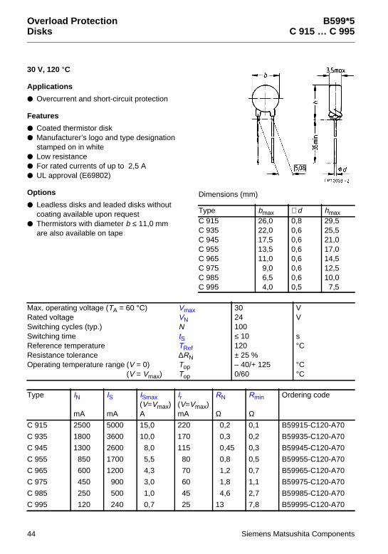
Overload ProtectionDisks
B599*5C 915 … C 995
30 V, 120 °C
Applications
Overcurrent and short-circuit protection
Features
Coated thermistor disk Manufacturer’s logo and type designation
stamped on in white Low resistance For rated currents of up to 2,5 A UL approval (E69802)
Options
Leadless disks and leaded disks withoutcoating available upon request
Thermistors with diameter b ≤ 11,0 mmare also available on tape
Max. operating voltage (TA = 60 °C) VmaxRated voltage VNSwitching cycles (typ.) NSwitching time tSReference temperature TRefResistance tolerance ∆RNOperating temperature range (V = 0) Top
(V = Vmax) Top
3024100≤ 10120± 25 %– 40/+ 1250/60
VV
s°C
°C°C
Type IN
mA
IS
mA
ISmax(V=Vmax)A
Ir(V=Vmax)mA
RN
Ω
Rmin
Ω
Ordering code
C 915 2500 5000 15,0 220 0,2 0,1 B59915-C120-A70
C 935 1800 3600 10,0 170 0,3 0,2 B59935-C120-A70
C 945 1300 2600 8,0 115 0,45 0,3 B59945-C120-A70
C 955 850 1700 5,5 80 0,8 0,5 B59955-C120-A70
C 965 600 1200 4,3 70 1,2 0,7 B59965-C120-A70
C 975 450 900 3,0 60 1,8 1,1 B59975-C120-A70
C 985 250 500 1,0 45 4,6 2,7 B59985-C120-A70
C 995 120 240 0,7 25 13 7,8 B59995-C120-A70
Dimensions (mm)
Type bmax ∅d hmaxC 915 26,0 0,8 29,5C 935 22,0 0,6 25,5C 945 17,5 0,6 21,0C 955 13,5 0,6 17,0C 965 11,0 0,6 14,5C 975 9,0 0,6 12,5C 985 6,5 0,6 10,0C 995 4,0 0,5 7,5
44 Siemens Matsushita Components

B599*5C 915 … C 995
Characteristics (typical)
PTC resistance RPTC versusPTC temperature TPTC(measured at low signal voltage)
PTC current IPTC versus PTC voltage VPTC(measured at 25 °C in still air)
Switching time tS versus switching current IS(measured at 25 °C in still air)
Rated current IN versus ambient temperature TA(measured in still air)
Siemens Matsushita Components 45

B599*5C 915 … C 995
Characteristics (typical)
PTC resistance RPTC versusPTC temperature TPTC(measured at low signal voltage)
PTC current IPTC versus PTC voltage VPTC(measured at 25 °C in still air)
Switching time tS versus switching current IS(measured at 25 °C in still air)
Rated current IN versus ambient temperature TA(measured in still air)
46 Siemens Matsushita Components

Overload ProtectionDisks
B599*0C 910 … C 990
54 V, 160 °C
Applications
Overcurrent and short-circuit protection
Features
Coated thermistor disk Manufacturer’s logo and type designation
stamped on in yellow UL approval (E69802)
Options
Leadless disks and leaded disks withoutcoating available upon request
Thermistors with diameter b ≤ 11,0 mmare also available on tape
Max. operating voltage (TA = 60 °C) VmaxRated voltage VNSwitching cycles (typ.) NSwitching time tSReference temperature TRefResistance tolerance ∆RNOperating temperature range (V = 0) Top
(V = Vmax) Top
5442100≤ 6160± 25 %– 40/+ 1250/60
VV
s°C
°C°C
Type IN
mA
IS
mA
ISmax(V=Vmax)A
Ir(V=Vmax)mA
RN
Ω
Rmin
Ω
Ordering code
C 910 1150 2370 15,0 110 0,9 0,6 B59910-C160-A70
C 930 770 1570 10,0 70 1,65 1,1 B59930-C160-A70
C 940 550 1140 8,0 50 2,3 1,5 B59940-C160-A70
C 950 360 730 5,5 35 3,7 2,4 B59950-C160-A70
C 960 280 560 4,3 30 5,6 3,7 B59960-C160-A70
C 970 170 355 3,0 25 9,4 6,2 B59970-C160-A70
C 980 95 200 1,0 20 25 16,5 B59980-C160-A70
C 990 55 120 0,7 15 55 36,3 B59990-C160-A70
Dimensions (mm)
Type bmax ∅d hmaxC 910 26,0 0,8 29,5C 930 22,0 0,6 25,5C 940 17,5 0,6 21,0C 950 13,5 0,6 17,0C 960 11,0 0,6 14,5C 970 9,0 0,6 12,5C 980 6,5 0,6 10,0C 990 4,0 0,5 7,5
Siemens Matsushita Components 47

B599*0C 910 … C 990
Characteristics (typical)
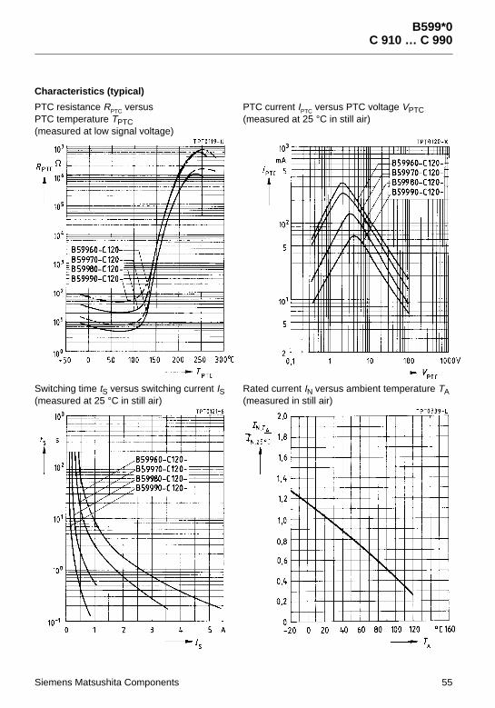
PTC resistance RPTC versusPTC temperature TPTC(measured at low signal voltage)
PTC current IPTC versus PTC voltage VPTC(measured at 25 °C in still air)
Switching time tS versus switching current IS(measured at 25 °C in still air)
Rated current IN versus ambient temperature TA(measured in still air)
48 Siemens Matsushita Components

B599*0C 910 … C 990
Characteristics (typical)
PTC resistance RPTC versusPTC temperature TPTC(measured at low signal voltage)
PTC current IPTC versus PTC voltage VPTC(measured at 25 °C in still air)
Switching time tS versus switching current IS(measured at 25 °C in still air)
Rated current IN versus ambient temperature TA(measured in still air)
Siemens Matsushita Components 49

Overload ProtectionDisks
B599*0C 910 … C 990
80 V, 80 °C
Applications
Overcurrent and short-circuit protection
Features
Coated thermistor disk Manufacturer’s logo and type designation
stamped on in black or red Short response times Reduced device temperature at Vmax
Options
Leadless disks and leaded disks withoutcoating available upon request
Thermistors with diameter b ≤ 11,0 mmare also available on tape
Max. operating voltage (TA = 60 °C) VmaxRated voltage VNSwitching cycles (typ.) NSwitching time tSReference temperature TRefResistance tolerance ∆RNOperating temperature range (V = 0) Top
(V = Vmax) Top
8063100≤ 280± 25 %– 40/+ 1250/60
VV
s°C
°C°C
Type IN
mA
IS
mA
ISmax(V=Vmax)A
Ir(V=Vmax)mA
RN
Ω
Rmin
Ω
Ordering code
C 910 530 1100 15,0 50 0,9 0,6 B59910-C80-A70
C 930 340 700 10,0 35 1,65 1,1 B59930-C80-A70
C 940 245 500 8,0 25 2,3 1,5 B59940-C80-A70
C 950 170 350 5,5 20 3,7 2,4 B59950-C80-A70
C 960 130 265 4,3 15 5,6 3,7 B59960-C80-A70
C 970 90 190 3,0 11 9,4 6,2 B59970-C80-A70
C 980 50 110 1,0 8 25 16,5 B59980-C80-A70
C 990 30 60 0,7 5 55 36,3 B59990-C80-A70
Dimensions (mm)
Type bmax ∅d hmaxC 910 26,0 0,8 29,5C 930 22,0 0,6 25,5C 940 17,5 0,6 21,0C 950 13,5 0,6 17,0C 960 11,0 0,6 14,5C 970 9,0 0,6 12,5C 980 6,5 0,6 10,0C 990 4,0 0,5 7,5
50 Siemens Matsushita Components

B599*0C 910 … C 990
Characteristics (typical)
PTC resistance RPTC versusPTC temperature TPTC(measured at low signal voltage)
PTC current IPTC versus PTC voltage VPTC(measured at 25 °C in still air)
Switching time tS versus switching current IS(measured at 25 °C in still air)
Rated current IN versus ambient temperature TA(measured in still air)
Siemens Matsushita Components 51

B599*0C 910 … C 990
Characteristics (typical)
PTC resistance RPTC versusPTC temperature TPTC(measured at low signal voltage)
PTC current IPTC versus PTC voltage VPTC(measured at 25 °C in still air)
Switching time tS versus switching current IS(measured at 25 °C in still air)
Rated current IN versus ambient temperature TA(measured in still air)
52 Siemens Matsushita Components

Overload ProtectionDisks
B599*0C 910 … C 990
80 V, 120 °C
Applications
Overcurrent and short-circuit protection
Features
Coated thermistor disk Manufacturer’s logo and type designation
stamped on in white UL approval (E69802)
Options
Leadless disks and leaded disks withoutcoating available upon request
Thermistors with diameter b ≤ 11,0 mmare also available on tape
Max. operating voltage (TA = 60 °C) VmaxRated voltage VNSwitching cycles (typ.) NSwitching time tSReference temperature TRefResistance tolerance ∆RNOperating temperature range (V = 0) Top
(V = Vmax) Top
8063100≤ 4120± 25 %– 40/+ 1250/60
VV
s°C
°C°C
Type IN
mA
IS
mA
ISmax(V=Vmax)A
Ir(V=Vmax)mA
RN
Ω
Rmin
Ω
Ordering code
C 910 1000 2000 15,0 65 0,9 0,6 B59910-C120-A70
C 930 700 1400 10,0 50 1,65 1,1 B59930-C120-A70
C 940 450 900 8,0 40 2,3 1,5 B59940-C120-A70
C 950 320 640 5,5 30 3,7 2,4 B59950-C120-A70
C 960 250 500 4,3 25 5,6 3,7 B59960-C120-A70
C 970 150 300 3,0 20 9,4 6,2 B59970-C120-A70
C 980 85 170 1,0 16 25 16,5 B59980-C120-A70
C 990 50 100 0,7 12 55 36,3 B59990-C120-A70
Dimensions (mm)
Type bmax ∅d hmaxC 910 26,0 0,8 29,5C 930 22,0 0,6 25,5C 940 17,5 0,6 21,0C 950 13,5 0,6 17,0C 960 11,0 0,6 14,5C 970 9,0 0,6 12,5C 980 6,5 0,6 10,0C 990 4,0 0,5 7,5
Siemens Matsushita Components 53

B599*0C 910 … C 990
Characteristics (typical)
PTC resistance RPTC versusPTC temperature TPTC(measured at low signal voltage)
PTC current IPTC versus PTC voltage VPTC(measured at 25 °C in still air)
Switching time tS versus switching current IS(measured at 25 °C in still air)
Rated current IN versus ambient temperature TA(measured in still air)
54 Siemens Matsushita Components
B599*0C 910 … C 990
Characteristics (typical)
PTC resistance RPTC versusPTC temperature TPTC(measured at low signal voltage)
PTC current IPTC versus PTC voltage VPTC(measured at 25 °C in still air)
Switching time tS versus switching current IS(measured at 25 °C in still air)
Rated current IN versus ambient temperature TA(measured in still air)
Siemens Matsushita Components 55

Overload ProtectionDisks
B598*0C 810 … C 890
160 V, 160 °C
Applications
Overcurrent and short-circuit protection
Features
Coated thermistor disk Manufacturer’s logo and type designation
stamped on in yellow UL approval (E69802)
Options
Leadless disks and leaded disks withoutcoating available upon request
Thermistors with diameter b ≤ 11,0 mmare also available on tape
Max. operating voltage (TA = 60 °C) VmaxRated voltage VNSwitching cycles (typ.) NSwitching time tSReference temperature TRefResistance tolerance ∆RNOperating temperature range (V = 0) Top
(V = Vmax) Top
160110100≤ 10160± 25 %– 25/+ 1250/60
VV
s°C
°C°C
Type IN
mA
IS
mA
ISmax(V=Vmax)A
Ir(V=Vmax)mA
RN
Ω
Rmin
Ω
Ordering code
C 810 800 1600 10,0 30 2,6 1,6 B59810-C160-A70
C 830 525 1050 7,0 24 3,7 2,2 B59830-C160-A70
C 840 400 800 4,1 18 6 3,6 B59840-C160-A70
C 850 250 500 2,2 16 10 6,0 B59850-C160-A70
C 860 180 360 1,5 13 15 7,8 B59860-C160-A70
C 870 125 250 1,0 11 25 13,1 B59870-C160-A70
C 880 70 140 0,4 8 70 36,7 B59880-C160-A70
C 890 35 70 0,2 6 150 78,7 B59890-C160-A70
Dimensions (mm)
Type bmax ∅d hmaxC 810 26,0 0,8 29,5C 830 22,0 0,6 25,5C 840 17,5 0,6 21,0C 850 13,5 0,6 17,0C 860 11,0 0,6 14,5C 870 9,0 0,6 12,5C 880 6,5 0,6 10,0C 890 4,0 0,5 7,5
56 Siemens Matsushita Components

B598*0C 810 … C 890
Characteristics (typical)
PTC resistance RPTC versusPTC temperature TPTC(measured at low signal voltage)
PTC current IPTC versus PTC voltage VPTC(measured at 25 °C in still air)
Switching time tS versus switching current IS(measured at 25 °C in still air)
Rated current IN versus ambient temperature TA(measured in still air)
Siemens Matsushita Components 57

B598*0C 810 … C 890
Characteristics (typical)
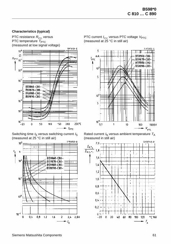
PTC resistance RPTC versusPTC temperature TPTC(measured at low signal voltage)
PTC current IPTC versus PTC voltage VPTC(measured at 25 °C in still air)
Switching time tS versus switching current IS(measured at 25 °C in still air)
Rated current IN versus ambient temperature TA(measured in still air)
58 Siemens Matsushita Components

Overload ProtectionDisks
B598*0C 810 … C 890
265 V, 80 °C
Applications
Overcurrent and short-circuit protection
Features
Coated thermistor disk Manufacturer’s logo and type designation
stamped on in black or red Short response times Reduced device temperature at Vmax
Options
Leadless disks and leaded disks withoutcoating available upon request
Thermistors with diameter b ≤ 11,0 mmare also available on tape
Max. operating voltage (TA = 60 °C) VmaxRated voltage VNSwitching cycles (typ.) NSwitching time tSReference temperature TRefResistance tolerance ∆RNOperating temperature range (V = 0) Top
(V = Vmax) Top
265220100≤ 680± 25 %– 25/+ 1250/60
VV
s°C
°C°C
Type IN
mA
IS
mA
ISmax(V=Vmax)A
Ir(V=Vmax)mA
RN
Ω
Rmin
Ω
Ordering code
C 810 350 710 10,0 20 2,6 1,6 B59810-C80-A70
C 830 250 510 7,0 15 3,7 2,2 B59830-C80-A70
C 840 170 350 4,1 10 6 3,6 B59840-C80-A70
C 850 110 230 2,2 8 10 6,0 B59850-C80-A70
C 860 90 180 1,5 6 15 7,8 B59860-C80-A70
C 870 60 130 1,0 5 25 13,1 B59870-C80-A70
C 880 30 70 0,4 4 70 36,7 B59880-C80-A70
C 890 15 40 0,2 3 150 78,7 B59890-C80-A70
Dimensions (mm)
Type bmax ∅d hmaxC 810 26,0 0,8 29,5C 830 22,0 0,6 25,5C 840 17,5 0,6 21,0C 850 13,5 0,6 17,0C 860 11,0 0,6 14,5C 870 9,0 0,6 12,5C 880 6,5 0,6 10,0C 890 4,0 0,5 7,5
Siemens Matsushita Components 59

B598*0C 810 … C 890
Characteristics (typical)
PTC resistance RPTC versusPTC temperature TPTC(measured at low signal voltage)
PTC current IPTC versus PTC voltage VPTC(measured at 25 °C in still air)
Switching time tS versus switching current IS(measured at 25 °C in still air)
Rated current IN versus ambient temperature TA(measured in still air)
60 Siemens Matsushita Components
B598*0C 810 … C 890
Characteristics (typical)
PTC resistance RPTC versusPTC temperature TPTC(measured at low signal voltage)
PTC current IPTC versus PTC voltage VPTC(measured at 25 °C in still air)
Switching time tS versus switching current IS(measured at 25 °C in still air)
Rated current IN versus ambient temperature TA(measured in still air)
Siemens Matsushita Components 61

Overload ProtectionDisks
B598*1C 811 … C 891
265 V, 135 °C
Applications
Overcurrent and short-circuit protection For enhanced rated current requirements
Features
Coated thermistor disk Surge-proof Manufacturer’s logo and type designation
stamped on in white
Options
Leadless disks and leaded disks withoutcoating available upon request
Thermistors with diameter b ≤ 11,0 mmare also available on tape
Max. operating voltage (TA = 60 °C) VmaxRated voltage VNSwitching cycles (typ.) NReference temperature TRefResistance tolerance ∆RNOperating temperature range (V = 0) Top
(V = Vmax) Top
265220100135± 25 %– 25/+ 1250/60
VV
°C
°C°C
Type IN
mA
IS
mA
ISmax(V=Vmax)A
tS
s
Ir(V=Vmax)mA
RN
Ω
Rmin
Ω
Ordering code
C 811 730 1450 10,0 <10 25 2,6 1,8 B59811-C135-A70
C 831 470 970 7,0 < 8 20 3,7 2,6 B59831-C135-A70
C 841 350 700 4,1 < 8 15 6 4,3 B59841-C135-A70
C 851 215 445 2,2 < 8 13 10 7,1 B59851-C135-A70
C 861 150 320 1,5 < 8 10 15 10,6 B59861-C135-A70
C 871 108 225 1,0 < 8 9 25 17,8 B59871-C135-A70
C 881 60 120 0,4 < 8 6 70 49,8 B59881-C135-A70
C 891 30 65 0,2 < 8 5 150 107 B59891-C135-A70
Dimensions (mm)
Type bmax ∅d hmaxC 811 26,0 0,8 29,5C 831 22,0 0,6 25,5C 841 17,5 0,6 21,0C 851 13,5 0,6 17,0C 861 11,0 0,6 14,5C 871 9,0 0,6 12,5C 881 6,5 0,6 10,0C 891 4,0 0,5 7,5
62 Siemens Matsushita Components

B598*1C 811 … C 891
Characteristics (typical)
PTC resistance RPTC versusPTC temperature TPTC(measured at low signal voltage)
PTC current IPTC versus PTC voltage VPTC(measured at 25 °C in still air)
Switching time tS versus switching current IS(measured at 25 °C in still air)
Rated current IN versus ambient temperature TA(measured in still air)
Siemens Matsushita Components 63

B598*1C 811 … C 891
Characteristics (typical)
PTC resistance RPTC versusPTC temperature TPTC(measured at low signal voltage)
PTC current IPTC versus PTC voltage VPTC(measured at 25 °C in still air)
Switching time tS versus switching current IS(measured at 25 °C in still air)
Rated current IN versus ambient temperature TA(measured in still air)
64 Siemens Matsushita Components

Overload ProtectionDisks
B598**C 810 … C 890
265 V to 550 V, 120 °C
Applications
Overcurrent and short-circuit protection
Features
Coated thermistor disk Manufacturer’s logo and type designation
stamped on in white UL approval (E69802) for all types
up to 265 V
Options
Leadless disks and leaded disks withoutcoating available upon request
Thermistors with diameter b ≤ 11,0 mmare also available on tape
VDE/ CECC approval for various265-V types upon request
Switching cycles (typ.) NSwitching time tSResistance tolerance ∆RNOperating temperature range (V = 0) Top
(V = Vmax) Top
100≤ 8± 25 %– 25/+ 1250/60
s
°C°C
Dimensions (mm)
Type bmax ∅d hmaxC 810 26,0 0,8 29,5C 830 22,0 0,6 25,5C 840 17,5 0,6 21,0C 850 13,5 0,6 17,0C 860 11,0 0,6 14,5C 870 9,0 0,6 12,5C 872 9,0 0,6 12,5C 873 9,0 0,6 12,5C 874 9,0 0,6 12,5C 875 9,0 0,6 12,5C 880 6,5 0,6 10,0C 883 6,5 0,6 10,0C 884 6,5 0,6 10,0C 885 6,5 0,6 10,0C 886 6,5 0,6 10,0C 890 4,0 0,5 7,5
Siemens Matsushita Components 65

B598**C 810 … C 890
Type IN
mA
IS
mA
ISmax(V=Vmax)A
Ir(V=Vmax)mA
RN
Ω
Rmin
Ω
Ordering code
Vmax = 265 V, VN = 220 V, TRef = 120 °CC 810 650 1300 10,0 25 2,6 1,6 B59810-C120-A70
C 830 460 920 7,0 20 3,7 2,4 B59830-C120-A70
C 840 330 660 4,1 15 6 3,8 B59840-C120-A70
C 850 200 400 2,2 13 10 6,4 B59850-C120-A70
C 860 140 280 1,5 10 15 9,0 B59860-C120-A70
C 870 100 200 1,0 9 25 15 B59870-C120-A70
C 872 80 160 1,0 9 35 21 B59872-C120-A70
C 873 70 140 1,0 9 45 27 B59873-C120-A70
C 874 60 125 1,0 9 55 31 B59874-C120-A70
C 875 55 110 1,0 9 65 36 B59875-C120-A70
C 880 55 110 0,4 6 70 39 B59880-C120-A70
C 883 35 70 0,4 5 120 67 B59883-C120-A70
C 890 30 60 0,2 5 150 84 B59890-C120-A70
Vmax = 420 V, VN = 380 V, TRef = 120 °CC 884 21 39 0,2 3 600 340 B59884-C120-A70
Vmax = 550 V, VN = 500 V, TRef = 110 °CC 885 15 30 0,1 3 1200 675 B59885-C120-A70
C 886 12 24 0,1 2 1500 840 B59886-C120-A70
66 Siemens Matsushita Components

B598**C 810 … C 890
Characteristics (typical)
PTC resistance RPTC versusPTC temperature TPTC(measured at low signal voltage)
PTC current IPTC versus PTC voltage VPTC(measured at 25 °C in still air)
Switching time tS versus switching current IS(measured at 25 °C in still air)
Rated current IN versus ambient temperature TA(measured in still air)
Siemens Matsushita Components 67

B598**C 810 … C 890
Characteristics (typical)
PTC resistance RPTC versusPTC temperature TPTC(measured at low signal voltage)
PTC current IPTC versus PTC voltage VPTC(measured at 25 °C in still air)
Switching time tS versus switching current IS(measured at 25 °C in still air)
Rated current IN versus ambient temperature TA(measured in still air)
68 Siemens Matsushita Components

B598**C 810 … C 890
Characteristics (typical)
PTC resistance RPTC versusPTC temperature TPTC(measured at low signal voltage)
PTC current IPTC versus PTC voltage VPTC(measured at 25 °C in still air)
Switching time tS versus switching current IS(measured at 25 °C in still air)
Rated current IN versus ambient temperature TA(measured in still air)
Siemens Matsushita Components 69

B598**C 810 … C 890
Characteristics (typical)
PTC resistance RPTC versusPTC temperature TPTC(measured at low signal voltage)
PTC current IPTC versus PTC voltage VPTC(measured at 25 °C in still air)
Switching time tS versus switching current IS(measured at 25 °C in still air)
Rated current IN versus ambient temperature TA(measured in still air)
70 Siemens Matsushita Components

Overload ProtectionDisks
B597**B 750 … B 774
420 V to 1000 V
Applications
Overcurrent and short-circuit protection
Features
Uncoated thermistor disk Marking stamped on in black UL appoval (E69802) for all types
up to 420 V (exception: B 758)
Switching cycles (typ.) NOperating temperature range (V = 0) Top
(V = Vmax) Top
100– 25/+ 1250/60
°C°C
Type IN
mA
IS
mA
ISmax(V=Vmax)A
tS
s
Ir(V=Vmax)mA
RN
Ω
Rmin
Ω
Ordering code
Vmax = 420 V, VN = 380 V, TRef = 120 °C, ∆RN = ± 25 %
B 750 123 245 2,0 < 6 4,0 25 13 B59750-B120-A70
B 751 87 173 2,0 < 4 3,5 50 26 B59751-B120-A70
B 752 69 137 2,0 < 4 3,5 80 42 B59752-B120-A70
B 770 64 127 1,4 < 4 3,5 70 45 B59770-B120-A70
B 753 56 112 2,0 < 3 3,0 120 63 B59753-B120-A70
B 754 50 100 2,0 < 3 3,0 150 68 B59754-B120-A70
B 771 49 97 1,4 < 3 2,5 120 76 B59771-B120-A70
B 772 43 86 1,4 < 3 2,5 150 96 B59772-B120-A70
Vmax = 550 V, VN = 500 V, TRef = 115 °C, ∆RN = ± 25 %
B 755 28 55 1,4 < 3 2,0 500 230 B59755-B115-A70
Vmax = 550 V, VN = 500 V, TRef = 120 °C, ∆RN = ± 25 %
B 773 24 48 1,0 < 3 2,0 500 320 B59773-B120-A70
Vmax = 550 V, VN = 500 V, TRef = 115 °C, ∆RN = ± 25 %
B 774 16 32 1,0 < 2 1,5 1100 700 B59774-B115-A70
Vmax = 1000 V, VN = 1000 V, TRef = 110 °C, ∆RN = ± 33 %
B 758 8 17 0,5 < 3 3,0 7500 3380 B59758-B110-A70
Dimensions (mm)
Type bmax hmax smaxB 75* 12,5 16,5 7,0B 77* 8,5 12,1 7,0
Siemens Matsushita Components 71

B597**B 750 … B 774
Characteristics (typical)
PTC resistance RPTC versusPTC temperature TPTC(measured at low signal voltage)
PTC current IPTC versus PTC voltage VPTC(measured at 25 °C in still air)
Switching time tS versus switching current IS(measured at 25 °C in still air)
Rated current IN versus ambient temperature TA(measured in still air)
72 Siemens Matsushita Components

B597**B 750 … B 774
Characteristics (typical)
PTC resistance RPTC versusPTC temperature TPTC(measured at low signal voltage)
PTC current IPTC versus PTC voltage VPTC(measured at 25 °C in still air)
Switching time tS versus switching current IS(measured at 25 °C in still air)
Rated current IN versus ambient temperature TA(measured in still air)
Siemens Matsushita Components 73

B597**B 750 … B 774
Characteristics (typical)
PTC resistance RPTC versusPTC temperature TPTC(measured at low signal voltage)
PTC current IPTC versus PTC voltage VPTC(measured at 25 °C in still air)
Switching time tS versus switching current IS(measured at 25 °C in still air)
Rated current IN versus ambient temperature TA(measured in still air)
74 Siemens Matsushita Components

B597**B 750 … B 774
Characteristics (typical)
PTC resistance RPTC versusPTC temperature TPTC(measured at low signal voltage)
PTC current IPTC versus PTC voltage VPTC(measured at 25 °C in still air)
Switching time tS versus switching current IS(measured at 25 °C in still air)
Rated current IN versus ambient temperature TA(measured in still air)
Siemens Matsushita Components 75

Overload ProtectionRods
B5940*B 404 … B 406
420 V to 550 V, 60 °C
Applications
Overcurrent and short-circuit protection For high operating voltages
Features
Leaded rod-type thermistor Low mounting height
Switching cycles (typ.) NSwitching time tSReference temperature TRefOperating temperature range (V = 0) Top
(V = Vmax) Top
100< 160– 25/+ 1250/40
s°C°C°C
Type IN
mA
IS
mA
ISmax(V=Vmax)A
Ir(V=Vmax)mA
RN
Ω
∆RN
%
Rmin
Ω
Ordering code
Vmax = 550 V, VN = 500 V
B 404 4 9 0,4 1,0 3500 ± 16 2880 B59404-B60-A40
Vmax = 500 V, VN = 500 V
B 406 2,5 6,5 0,3 1,0 5500 ± 28 3800 B59406-B60-A40
Dimensions (mm)
Type ImaxB 404, B 406 12,5 ± 1 17
76 Siemens Matsushita Components

B5940*B 404 … B 406
Characteristics (typical)
PTC resistance RPTC versusPTC temperature TPTC(measured at low signal voltage)
PTC current IPTC versus PTC voltage VPTC(measured at 25 °C in still air)
Switching time tS versus switching current IS(measured at 25 °C in still air)
Siemens Matsushita Components 77

Overload ProtectionTelecom Disks
B5902*S 102*
245 V, 120 °C
Applications
Overload protection in telecomequipment (switching systemsand subscriber sets)
Features
Uncoated thermistor disk Marked with manufacturer’s logo and
type designation Narrow tolerance on resistance Impulse-tested in accordance with
IEC 60-2, VDE 0433: 8/20 µs 600-V-tested upon request
Options
Alternative tolerances upon request Leadless and single-ended disks
upon request Also available on tape
Max. operating voltage (TA = 60 °C) VmaxRated voltage VNSwitching cycles (typ.) NSwitching time tSReference temperature TRefResistance tolerance ∆RNPulse strength VPOperating temperature range (V = 0) Top
(V = Vmax) Top
245220150≤ 8120± 15 %1000– 25/+ 1250/60
VV
s°C
V°C°C
Type IN
mA
IS
mA
ISmax(V=Vmax)A
Ir(V=Vmax)mA
RN
Ω
Rmin
Ω
Ordering code
S 1022 200 400 2,5 10 10 7,5 B59022-S1120-A70
S 1023 100 200 2,8 10 25 15 B59023-S1120-A70
S 1024 80 160 1,0 9 35 25 B59024-S1120-A70
S 1025 55 110 0,4 6 70 55 B59025-S1120-A70
Dimensions (mm)
Type bmax hmax sS 1022 10,2 14,1 4,0S 1023 8,2 12,1 4,0S 1024 8,2 12,1 4,0S 1025 6,6 10,5 4,0
78 Siemens Matsushita Components

B5902*S 102*
Characteristics (typical)
PTC resistance RPTC versusPTC temperature TPTC(measured at low signal voltage)
PTC current IPTC versus PTC voltage VPTC(measured at 25 °C in still air)
Switching time tS versus switching current IS(measured at 25 °C in still air)
Rated current IN versus ambient temperature TA(measured in still air)
Siemens Matsushita Components 79

Overload ProtectionSMDs
B59*07A 1*07
80 V, 120 °C
Applications
Overcurrent protection Time delay Current stabilization
Features
Thermistor chip with silver terminations Small size Short response times Suitable for reflow soldering,
also for conductive adhesion Suitable for automatic placement Available on tape
(standard delivery mode)
1) Measured peak-to-peak
Switching cycles (typ.) NReference temperature TRefPTC temperature (V = Vmax) TPTCResistance tolerance ∆RNOperating temperature range (V = 0) Top
(V = Vmax) Top
100120190± 25 %– 40/+ 1250/60
°C°C
°C°C
Type IN1)
mA
IS1)
mA
ISmax(V=Vmax)A
RN
Ω
Rmin
Ω
tS
s
Ordering code
Vmax = 80 V, VN = 63 V
A 1707 45 90 0,3 125 75 < 2,5 B59707-A1120-A62
Vmax = 30 V, VN = 24 V
A 1607 65 130 0,4 55 30 < 5,0 B59607-A1120-A62
Dimensions (mm)Tolerances (I, b, h) ± 0,2 mm
Type I b h SizeA 1607 3,2 2,5 1,7 1210A 1707 3,2 2,5 1,7 1210
Termination
80 Siemens Matsushita Components

B59*07A 1*07
Characteristics (typical)
PTC resistance RPTC versusPTC temperature TPTC(measured at low signal voltage)
Rated current IN versus ambient temperature TA(measured in still air)
Siemens Matsushita Components 81

Overload ProtectionSMDs
B59*01P 1*01
30 V
Applications
Overcurrent protection Short-circuit protection
Features
Molded epoxy encapsuation,tinned solder terminals
Suitable for wave and reflow soldering Suitable for automatic placement Available on tape
(standard delivery mode)
Max. operating voltage (TA = 60 °C) VmaxRated voltage VNSwitching cycles (typ.) NResistance tolerance ∆RNOperating temperature range (V = 0) Top
(V = Vmax) Top
3024100± 25 %– 40/+ 1250/60
VV
°C°C
Type IN
mA
IS
mA
ISmax(V=Vmax)A
Ir(V=Vmax)mA
RN
Ω
Rmin
Ω
tS(ISmax)s
Ordering code
Reference temperature TRef = 80 °CP 1101 90 185 0,7 25 13 7,80 ≤ 1,5 B59101-P1080-A62
P 1201 165 340 1,0 34 4,6 2,70 ≤ 6,0 B59201-P1080-A62
P 1301 205 420 1,6 38 3,1 1,85 ≤ 6,0 B59301-P1080-A62
Reference temperature TRef = 120 °CP 1101 170 355 0,7 35 13 7,80 ≤ 3,0 B59101-P1120-A62
P 1201 265 545 1,0 45 4,6 2,70 ≤ 12,0 B59201-P1120-A62
P 1301 310 640 1,6 53 3,1 1,85 ≤ 12,0 B59301-P1120-A62
Dimensions (mm)Tolerances ± 0,5 mm
Type h b I x SizeP 1101 3,2 6,3 8,0 1,7 3225P 1201 3,2 6,3 8,0 1,7 3225P 1301 3,2 8,0 10,0 2,3 4032
Termination
82 Siemens Matsushita Components

B59*01P 1*01
Characteristics (typical)
PTC resistance RPTC versusPTC temperature TPTC(measured at low signal voltage)
PTC current IPTC versus PTC voltage VPTC(measured at 25 °C in still air)
Switching time tS versus switching current IS(measured at 25 °C in still air)
Rated current IN versus ambient temperature TA(measured in still air)
Siemens Matsushita Components 83

B59*01P 1*01
Characteristics (typical)
PTC resistance RPTC versusPTC temperature TPTC(measured at low signal voltage)
PTC current IPTC versus PTC voltage VPTC(measured at 25 °C in still air)
Switching time tS versus switching current IS(measured at 25 °C in still air)
Rated current IN versus ambient temperature TA(measured in still air)
84 Siemens Matsushita Components

Overload ProtectionSMDs
B59*15P 1*15
80 V
Applications
Overcurrent protection Short-circuit protection
Features
Molded epoxy encapsuation,tinned solder terminals
Suitable for wave and reflow soldering Suitable for automatic placement Available on tape
(standard delivery mode)
Max. operating voltage (TA = 60 °C) VmaxRated voltage VNSwitching cycles (typ.) NResistance tolerance ∆RNOperating temperature range (V = 0) Top
(V = Vmax) Top
8063100± 25 %– 40/+ 1250/60
VV
°C°C
Type IN
mA
IS
mA
ISmax(V=Vmax)A
Ir(V=Vmax)mA
RN
Ω
Rmin
Ω
tS(ISmax)s
Ordering code
Reference temperature TRef = 80 °CP 1115 40 85 0,7 9,0 55 32,2 ≤ 0,5 B59115-P1080-A62
P 1215 65 135 1,0 11,5 25 15,0 ≤ 1,5 B59215-P1080-A62
P 1315 80 165 1,6 15,0 16 9,6 ≤ 1,5 B59315-P1080-A62
Reference temperature TRef = 120 °CP 1115 70 145 0,7 13,0 55 32,2 ≤ 1,0 B59115-P1120-A62
P 1215 100 210 1,0 14,0 25 15,0 ≤ 3,0 B59215-P1120-A62
P 1315 150 310 1,6 20,0 16 9,6 ≤ 3,0 B59315-P1120-A62
Dimensions (mm)Tolerances ± 0,5 mm
Type h b I x SizeP 1115 3,2 6,3 8,0 1,7 3225P 1215 3,2 6,3 8,0 1,7 3225P 1315 3,2 8,0 10,0 2,3 4032
Termination
Siemens Matsushita Components 85

B59*15P 1*15
Characteristics (typical)
PTC resistance RPTC versusPTC temperature TPTC(measured at low signal voltage)
PTC current IPTC versus PTC voltage VPTC(measured at 25 °C in still air)
Switching time tS versus switching current IS(measured at 25 °C in still air)
Rated current IN versus ambient temperature TA(measured in still air)
86 Siemens Matsushita Components

B59*15P 1*15
Characteristics (typical)
PTC resistance RPTC versusPTC temperature TPTC(measured at low signal voltage)
PTC current IPTC versus PTC voltage VPTC(measured at 25 °C in still air)
Switching time tS versus switching current IS(measured at 25 °C in still air)
Rated current IN versus ambient temperature TA(measured in still air)
Siemens Matsushita Components 87

Degaussing B59*50C 1*50
265 V
Applications
Degaussing of picture tubes
Features
Coated thermistor disk Marked with manufacturer’s logo and
type designation Low residual current Stable performance throughout a
large number of switching cycles
Options
Also available on tape
Max. operating voltage VmaxRated voltage VNOperating temperature range (V = 0) Top
(V = Vmax) Top
265230-25/+1250/60
VrmsVrms°C°C
Type Iin/coil (0 s)
App
Ir/coil (180 s)
mApp
RNΩ
RcoilΩ
Ordering code
Reference temperature TRef = 75 °CC 1250 ≥11
(265 Veff)≤ 22,5(200 Vrms)
25 25 B59250-C1080-B70
Reference temperature TRef = 80 °CC 1450 ≥ 20
(230 Veff)≤ 30(230 Vrms)
18 12 B59450-C1080-B70
Dimensions (mm)
Type bmax smax ∅d hmaxC 1250 13,5 5,0 0,6 17,0C 1450 15,0 5,0 0,6 19,0
88 Siemens Matsushita Components
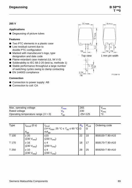
Degaussing B 59**0T **0
265 V
Applications
Degaussing of picture tubes
Features
Two PTC elements in a plastic case Low residual current due to
double PTC configuration Marked with manufacurer’s logo, type
designation and date code Flame-retardant case material (UL 94 V-0) Solderability to IEC 68-2-20 (test ta, methode 1) Stable performance throughout a large number
of switching cycles owing to clamp contacting EN 144003 compliance
Connection
Connection to power supply: AB Connection to coil: CA
Max. operating voltage VmaxRated voltage VNOperating temperature range (V = 0) Top
265230-25/+125
VrmsVrms°C
Type Iin/coil (0 s)
App
Ir/coil(V=Vmax, 25 °C ≤ Top ≤ 60 °C)mApp
RNΩ
RcoilΩ
Ordering code
T 100 ≥ 20(230 Vrms)
≤15(230 Vrms)
22 10 B59100-T 80-A10
T 170 ≥ 16(230 Vrms)
≤ 4(230 Vrms)
18 17 B59170-T 80-A10
T 250 ≥ 10(230 Vrms)
≤ 4(230 Vrms)
28 25 B59250-T 80-A10
Top view 1 mm pin width
Siemens Matsushita Components 89

B 59**0T **0
Characteristics
Typical curve of demagnetization current Iin/coilCoil resistance: 25 Ω (T 250), 17 Ω (T 170), 10 Ω (T 100)Ambient temperature 25°CT 100 T 170
T 250
Iin
Iin
Iin
90 Siemens Matsushita Components

Switching B5911*C 111*
265 V
Applications
Switching thermistor for lighting applications(e. g. in electronic ballasts for lamps etc.)
For frequent switching
Features
Coated thermistor disk,kinked leads
Marked with manufacturer’s logo andtype designation
Stable performance throughout10 000 switching cycles
Options
Also available on tape
Max. operating voltage (TA = 60 °C) VmaxRated voltage VNSwitching cycles (typ.) NResistance tolerance ∆RNOperating temperature range (V = 0) Top
(V = Vmax) Top
26522010000± 25 %– 25/+ 1250/60
VV
°C°C
Type IN
mA
IS
mA
ISmax(V=Vmax)mA
Ir(V=Vmax)mA
RN
Ω
Rmin
Ω
tS
s
Ordering code
Reference temperature TRef = 80 °CC 1118 30 70 400 4 70 39 ≤ 6,0 B59118-C1080-A70
C 1119 15 40 200 3 150 84 ≤ 6,0 B59119-C1080-A70
Reference temperature TRef = 120 °CC 1118 55 110 400 6 70 39 ≤ 8,0 B59118-C1120-A70
C 1119 30 60 200 5 150 84 ≤ 8,0 B59119-C1120-A70
Dimensions (mm)
Type bmax hmax ∅dC 1118 6,5 10,0 0,6C 1119 4,0 7,5 0,5
Siemens Matsushita Components 91
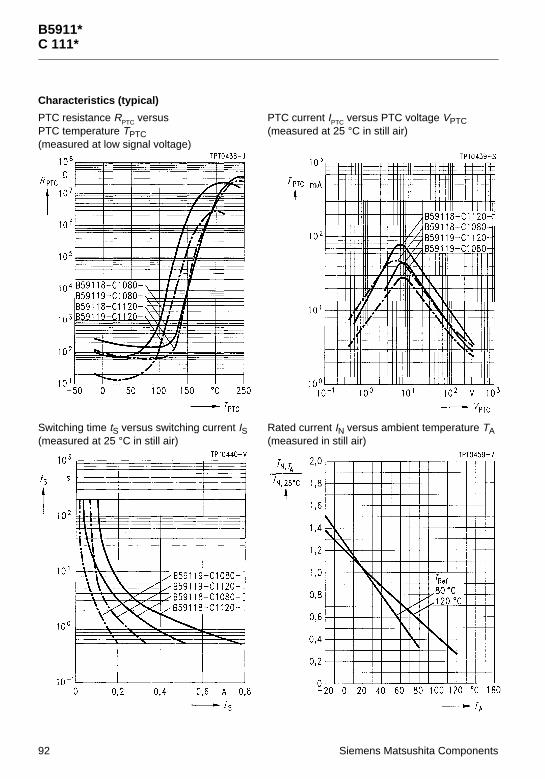
B5911*C 111*
Characteristics (typical)
PTC resistance RPTC versusPTC temperature TPTC(measured at low signal voltage)
PTC current IPTC versus PTC voltage VPTC(measured at 25 °C in still air)
Switching time tS versus switching current IS(measured at 25 °C in still air)
Rated current IN versus ambient temperature TA(measured in still air)
92 Siemens Matsushita Components

Switching B59**0J **0
265 V
Applications
Delayed switching of loads(e. g. in electronic ballasts for lamps)
For frequent switching
Features
Encased thermistor disk withclamp contacts
Flame-retardant plastic case Case material UL-listed Silver-plated solder pins Manufacturer’s logo and type designation
stamped on in white Stable performance throughout
100 000 switching cycles
Switching cycles (typ.) NSwitching time tSResistance tolerance ∆RNOperating temperature range (V = 0) Top
(V = Vmax) Top
100000≤ 5± 25 %– 25/+ 1250/60
s
°C°C
Type TRef
°C
IN
mA
IS
mA
ISmax(V=Vmax)A
Ir(V=Vmax)mA
RN
Ω
Rmin
Ω
Ordering code
Vmax = 265 V, VN = 220 V
J 150 120 35 70 0,45 4 150 84 B59150-J120-A20
J 200 120 30 60 0,42 4 200 110 B59200-J120-A20
J 320 120 24 50 0,33 4 320 200 B59320-J120-A20
Dimensions (mm)
Siemens Matsushita Components 93

Switching B59339J 280 … J 290
80 V to 265 V
Applications
Delayed switching of loads For frequent switching
Features
Encased thermistor disk withclamp contacts
Flame-retardant plastic case Case material UL-listed Silver-plated solder pins Manufacturer’s logo and type designation
stamped on in white Stable performance throughout
50 000 switching cycles
Switching cycles (typ.) NSwitching time tSResistance tolerance ∆RNOperating temperature range (V = 0) Top
(V = Vmax) Top
50000≤ 0,5± 25 %– 25/+ 1250/60
s
°C°C
Type TRef
°C
IN
mA
IS
mA
ISmax(V=Vmax)A
Ir(V=Vmax)mA
RN
Ω
Rmin
Ω
Ordering code
Vmax = 80 V, VN = 63 V
J 280 120 77 150 1,10 14 32 20 B59339-A1320-P20
J 281 120 60 120 0,90 10 50 31 B59339-A1500-P20
Vmax = 160 V, VN = 110 V
J 282 120 48 100 0,70 6,0 80 50 B59339-A1800-P20
J 283 120 39 80 0,58 5,0 120 75 B59339-A1121-P20
Vmax = 265 V, VN = 220 V
J 284 120 30 60 0,42 4,0 200 110 B59339-A1201-P20
J 285 120 24 50 0,33 4,0 320 200 B59339-A1321-P20
J 286 120 20 40 0,27 3,5 500 260 B59339-A1501-P20
J 287 120 15 30 0,22 3,0 800 480 B59339-A1801-P20
J 288 120 13 26 0,18 2,5 1200 630 B59339-A1122-P20
J 289 120 10 20 0,15 2,0 2000 900 B59339-A1202-P20
J 290 115 8 16 0,12 1,5 3200 1500 B59339-A1322-P20
Dimensions (mm)
94 Siemens Matsushita Components

B59339J 280 … J 290
Characteristics (typical)
PTC resistance RPTC versusPTC temperature TPTC(measured at low signal voltage)
PTC current IPTC versus PTC voltage VPTC(measured at 25 °C in still air)
Switching time tS versus switching current IS(measured at 25 °C in still air)
Siemens Matsushita Components 95

B59339J 280 … J 290
Characteristics (typical)
PTC resistance RPTC versusPTC temperature TPTC(measured at low signal voltage)
PTC current IPTC versus PTC voltage VPTC(measured at 25 °C in still air)
Switching time tS versus switching current IS(measured at 25 °C in still air)
96 Siemens Matsushita Components

B59339J 280 … J 290
Characteristics (typical)
PTC resistance RPTC versusPTC temperature TPTC(measured at low signal voltage)
PTC current IPTC versus PTC voltage VPTC(measured at 25 °C in still air)
Switching time tS versus switching current IS(measured at 25 °C in still air)
Siemens Matsushita Components 97

Switching B593**J 29
265 V
Applications
Starting resistance in switch-modepower supplies
Features
Encased thermistor disk withclamp contacts
Flame-retardant plastic case Case material UL-listed Silver-plated solder pins Manufacturer’s logo and type designation
stamped on in white Stable performance throughout
50 000 switching cycles
Max. operating voltage (TA = 60 °C) VmaxRated voltage VNSwitching cycles (typ.) NRated resistance RNResistance tolerance ∆RNOperating temperature range (V = 0) Top
(V = Vmax) Top
265220500005000± 25 %– 25/+ 1250/60
VV
Ω
°C°C
Type TRef
°C
IN
mA
IS
mA
ISmax(V=Vmax)A
tS
s
Ir(V=Vmax)mA
Rmin
Ω
Ordering code
J 29 115 7 15 0,1 ≤ 0,5 1,5 1500 B59339-A1502-P20
J 29 150 10 20 0,1 ≤ 1,0 1,8 2200 B59342-A1502-P20
J 29 190 14 30 0,1 ≤ 2,0 2,0 2200 B59346-A1502-P20
Dimensions (mm)
98 Siemens Matsushita Components

B593**J 29
Characteristics (typical)
PTC resistance RPTC versusPTC temperature TPTC(measured at low signal voltage)
PTC current IPTC versus PTC voltage VPTC(measured at 25 °C in still air)
Switching time tS versus switching current IS(measured at 25 °C in still air)
B593** B593**
B593**
Siemens Matsushita Components 99

Motor Starting B5919*, B5921*A 19*, A 21*, J 19*, J 21*
175 V to 400 V
Applications
Time delay Motor starting Time delay in turning off the auxiliary winding of single-phase ac motors
Features
Two versions available Version A:
Uncoated, metallized disk for clamp-contactingUL approval for all types with the exception of A 196
Version J:Thermistor disk encapsulated in heat-resistant, flame-retardant plastic casewith connections for compressor power supplies and tab connectors;other cases and other terminal options upon request
Switching cycles NOperating temperature range (V = 0) Top
(V = Vmax) Top
> 1000005/805/80
°C°C
Type Vmax
V
Imax
A
TRef
°C
VD
V
RN ± ∆R(VPTC ≤ 2,5 V)Ω
Ir
mA
A 192 325 8 120 > 650 25 + 20/– 20 % 12
A 196 350 8 120 > 700 15 +/– 30 % 12
A 501 355 6 135 700 33 ± 30 % 9
A 502 400 4 120 750 47 ± 20 % 9
J 501 355 6 135 700 33 ± 30 % 9
J 502 400 4 120 750 47 ± 20 % 9
100 Siemens Matsushita Components

B5919*, B5921*A 19*, A 21*, J 19*, J 21*
Type Tsurf
°C
tS
s
Ordering code
A 192 175 0,6 B59192-A120-A10
A 196 175 0,9 B59196-A120-A10
A 501 180 0,8 B59501-A135-A10
A 502 170 0,7 B59502-A120-A10
J 501 – 0,8 B59501-J135-A110
J 502 – 0,7 B59502-J120-A110
Termination
Version A Version J
Dimensions (mm)
Type b sA 192 20,5 + 0,5/– 1,0 2,5 ± 0,2A 196 20,5 + 0,5/– 1,0 3,2 ± 0,2A 501 19,5 2,5 ± 0,2A 502 19,5 2,5 ± 0,2
Siemens Matsushita Components 101

Motor and Machine Protection B59100M 1100
Applications
Thermal protection of winding in electric motors Limit temperature monitoring
Features
Thermistor pellet with insulating encapsulation Low-resistance type Silver-plated and Teflon(PTFE)-insulated AWG 26 litz wires Trip temperature coded in litz wire color Extremely fast response due to small dimensions Characteristics for nominal threshold temperatures of 90 bis 160 °C conform with DIN 44 081 Can be used in conjunction with Siemens tripping units
Max. operating voltage (TA = 0 … 40 °C) VmaxMax. measuring voltage (TA – 25 K … TNAT + 15 K) VMes,maxRated resistance (VPTC ≤ 2,5 V) RNInsulation test voltage VisResponse time taOperating temperature range(V = 0) Top
(V = Vmax) Top
307,5≤ 1002,5< 3– 25/+ 1800/40
VVΩkV acs°C°C
Type TNAT ± ∆T
°C
R (TNAT – ∆T)(VPTC ≤ 2,5 V)Ω
R (TNAT + ∆T)(VPTC ≤ 2,5 V)Ω
R (TNAT + 15 K)(VPTC ≤ 7,5 V)Ω
R (TNAT + 23 K)(VPTC ≤ 2,5 V)Ω
M 1100 60 ± 5 ≤ 570 ≥ 570 — ≥ 10 k
M 1100 70 ± 5 ≤ 570 ≥ 570 — ≥ 10 k
M 1100 80 ± 5 ≤ 570 ≥ 570 — —
M 1100 90 ± 5 ≤ 550 ≥ 1330 ≥ 4 k —
M 1100 100 ± 5 ≤ 550 ≥ 1330 ≥ 4 k —
M 1100 110 ± 5 ≤ 550 ≥ 1330 ≥ 4 k —
M 1100 120 ± 5 ≤ 550 ≥ 1330 ≥ 4 k —
M 1100 130 ± 5 ≤ 550 ≥ 1330 ≥ 4 k —
M 1100 140 ± 5 ≤ 550 ≥ 1330 ≥ 4 k —
M 1100 145 ± 5 ≤ 550 ≥ 1330 ≥ 4 k —
M 1100 150 ± 5 ≤ 550 ≥ 1330 ≥ 4 k —
M 1100 155 ± 5 ≤ 550 ≥ 1330 ≥ 4 k —
M 1100 160 ± 5 ≤ 550 ≥ 1330 ≥ 4 k —
M 1100 170 ± 7 ≤ 570 ≥ 570 — ≥ 10 k
M 1100 180 ± 7 ≤ 570 ≥ 570 — ≥ 10 k
M 1100 190 ± 7 ≤ 570 ≥ 570 — ≥ 10 k
102 Siemens Matsushita Components

B59100M 1100
Type Color codingof litz wires
Ordering code
M 1100 white/grey B59100-M1060-A70
M 1100 white/brown B59100-M1070-A70
M 1100 white/white B59100-M1080-A70
M 1100 green/green B59100-M1090-A70
M 1100 red/red B59100-M1100-A70
M 1100 brown/brown B59100-M1110-A70
M 1100 grey/grey B59100-M1120-A70
M 1100 blue/blue B59100-M1130-A70
M 1100 white/blue B59100-M1140-A70
M 1100 white/black B59100-M1145-A70
M 1100 black/black B59100-M1150-A70
M 1100 blue/black B59100-M1155-A70
M 1100 blue/red B59100-M1160-A70
M 1100 white/green B59100-M1170-A70
M 1100 white/red B59100-M1180-A70
M 1100 black/grey B59100-M1190-A70
Dimensions in mm
Siemens Matsushita Components 103

B59100M 1100
Characteristics (typical)
PTC resistance RPTC versus PTC temperature TPTC(measured at low signal voltage)
PTC resistance RPTC versus PTC temperature TPTC(measured at low signal voltage)
104 Siemens Matsushita Components

B59100M 1100
Characteristics (typical)
PTC resistance RPTC versus PTC temperature TPTC(measured at low signal voltage)
Siemens Matsushita Components 105

Motor and Machine Protection B59300M 1300
Applications
Thermal protection of winding in electric motors Limit temperature monitoring
Features
Thermistor pellets with insulating encapsulation in series connection (triple sensor) Low-resistance type Silver-plated and Teflon(PTFE)-insulated AWG 26 litz wires Trip temperature coded in litz wire color,
connecting wires all yellow Characteristics for nominal threshold temperatures of 90 bis 160 °C conform with DIN 44 082 Can be used in conjunction with Siemens tripping units
Max. operating voltage (TA = 0 … 40 °C) VmaxMax. measuring voltage (TA – 25 K … TNAT + 15 K) VMes,maxRated resistance (VPTC ≤ 2,5 V) RNInsulation test voltage VisResponse time taOperating temperature range(V = 0) Top
(V = Vmax) Top
307,5≤ 3002,5< 3– 25/+ 1800/40
VVΩkV acs°C°C
Type TNAT ± ∆T
°C
R (TNAT – ∆T)(VPTC ≤ 2,5 V)Ω
R (TNAT + ∆T)(VPTC ≤ 2,5 V)Ω
R (TNAT + 15 K)(VPTC ≤ 7,5 V)Ω
R (TNAT + 23 K)(VPTC ≤ 2,5 V)Ω
M 1300 60 ± 5 ≤ 1710 ≥ 1710 — ≥ 30 k
M 1300 70 ± 5 ≤ 1710 ≥ 1710 — ≥ 30 k
M 1300 80 ± 5 ≤ 1710 ≥ 1710 — ≥ 30 k
M 1300 90 ± 5 ≤ 1650 ≥ 3990 ≥ 12 k —
M 1300 100 ± 5 ≤ 1650 ≥ 3990 ≥ 12 k —
M 1300 110 ± 5 ≤ 1650 ≥ 3990 ≥ 12 k —
M 1300 120 ± 5 ≤ 1650 ≥ 3990 ≥ 12 k —
M 1300 130 ± 5 ≤ 1650 ≥ 3990 ≥ 12 k —
M 1300 140 ± 5 ≤ 1650 ≥ 3990 ≥ 12 k —
M 1300 145 ± 5 ≤ 1650 ≥ 3990 ≥ 12 k —
M 1300 150 ± 5 ≤ 1650 ≥ 3990 ≥ 12 k —
M 1300 155 ± 5 ≤ 1650 ≥ 3990 ≥ 12 k —
M 1300 160 ± 5 ≤ 1650 ≥ 3990 ≥ 12 k —
M 1300 170 ± 7 ≤ 1710 ≥ 1710 — ≥ 30 k
M 1300 180 ± 7 ≤ 1710 ≥ 1710 — ≥ 30 k
M 1300 190 ± 7 ≤ 1710 ≥ 1710 — ≥ 30 k
106 Siemens Matsushita Components

B59300M 1300
Type Color codingof litz wires
Ordering code
M 1300 white/grey B59300-M1060-A70
M 1300 white/brown B59300-M1070-A70
M 1300 white/white B59300-M1080-A70
M 1300 green/green B59300-M1090-A70
M 1300 red/red B59300-M1100-A70
M 1300 brown/brown B59300-M1110-A70
M 1300 grey/grey B59300-M1120-A70
M 1300 blue/blue B59300-M1130-A70
M 1300 white/blue B59300-M1140-A70
M 1300 white/black B59300-M1145-A70
M 1300 black/black B59300-M1150-A70
M 1300 blue/black B59300-M1155-A70
M 1300 blue/red B59300-M1160-A70
M 1300 white/green B59300-M1170-A70
M 1300 white/red B59300-M1180-A70
M 1300 black/grey B59300-M1190-A70
Dimensions in mm
Siemens Matsushita Components 107

B59300M 1300
Characteristics (typical)
PTC resistance RPTC versus PTC temperature TPTC(measured at low signal voltage)
PTC resistance RPTC versus PTC temperature TPTC(measured at low signal voltage)
108 Siemens Matsushita Components
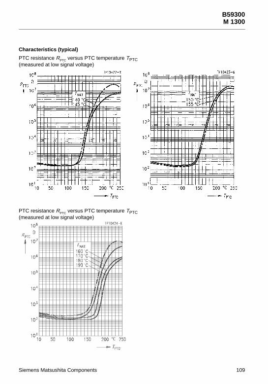
B59300M 1300
Characteristics (typical)
PTC resistance RPTC versus PTC temperature TPTC(measured at low signal voltage)
PTC resistance RPTC versus PTC temperature TPTC(measured at low signal voltage)
Siemens Matsushita Components 109

Motor and Machine Protection B59135M 135
Applications
Thermal protection of winding in electric motors Limit temperature monitoring
Features
Thermistor pellet with insulating encapsulation Silver-plated and Teflon(PTFE)-insulated AWG 26 litz wires Trip temperature coded in litz wire color Extremely fast response due to small dimensions Characteristics for nominal threshold temperatures of 90 bis 160 °C conform with DIN 44 081 Can be used in conjunction with Siemens tripping units
Max. operating voltage (TA = 0 … 40 °C) VmaxMax. measuring voltage (TA – 25 K … TNAT + 15 K) VMes,maxRated resistance (VPTC ≤ 2,5 V) RNInsulation test voltage VisResponse time taOperating temperature range(V = 0) Top
(V = Vmax) Top
307,5≤ 2502,5< 3– 25/+ 1800/40
VVΩkV acs°C°C
Type TNAT ± ∆T
°C
R (TNAT – ∆T)(VPTC ≤ 2,5 V)Ω
R (TNAT + ∆T)(VPTC ≤ 2,5 V)Ω
R (TNAT + 15 K)(VPTC ≤ 7,5 V)Ω
R (TNAT + 23 K)(VPTC ≤ 2,5 V)Ω
M 135 60 ± 5 ≤ 570 ≥ 570 — ≥ 4 k
M 135 70 ± 5 ≤ 570 ≥ 570 — ≥ 4 k
M 135 80 ± 5 ≤ 570 ≥ 570 — ≥ 4 k
M 135 90 ± 5 ≤ 550 ≥ 1330 ≥ 4 k —
M 135 100 ± 5 ≤ 550 ≥ 1330 ≥ 4 k —
M 135 110 ± 5 ≤ 550 ≥ 1330 ≥ 4 k —
M 135 120 ± 5 ≤ 550 ≥ 1330 ≥ 4 k —
M 135 130 ± 5 ≤ 550 ≥ 1330 ≥ 4 k —
M 135 140 ± 5 ≤ 550 ≥ 1330 ≥ 4 k —
M 135 145 ± 5 ≤ 550 ≥ 1330 ≥ 4 k —
M 135 150 ± 5 ≤ 550 ≥ 1330 ≥ 4 k —
M 135 155 ± 5 ≤ 550 ≥ 1330 ≥ 4 k —
M 135 160 ± 5 ≤ 550 ≥ 1330 ≥ 4 k —
M 135 170 ± 7 ≤ 570 ≥ 570 — ≥ 4 k
M 135 180 ± 7 ≤ 570 ≥ 570 — ≥ 4 k
110 Siemens Matsushita Components

B59135M 135
Type Color codingof litz wires
Ordering code
M 135 white/grey B59135-M60-A70
M 135 white/brown B59135-M70-A70
M 135 white/white B59135-M80-A70
M 135 green/green B59135-M90-A70
M 135 red/red B59135-M100-A70
M 135 brown/brown B59135-M110-A70
M 135 grey/grey B59135-M120-A70
M 135 blue/blue B59135-M130-A70
M 135 white/blue B59135-M140-A70
M 135 white/black B59135-M145-A70
M 135 black/black B59135-M150-A70
M 135 blue/black B59135-M155-A70
M 135 blue/red B59135-M160-A70
M 135 white/green B59135-M170-A70
M 135 white/red B59135-M180-A70
Dimensions in mm
Siemens Matsushita Components 111

B59135M 135
Characteristics (typical)
PTC resistance RPTC versus PTC temperature TPTC(measured at low signal voltage)
PTC resistance RPTC versus PTC temperature TPTC(measured at low signal voltage)
112 Siemens Matsushita Components

B59135M 135
Characteristics (typical)
PTC resistance RPTC versus PTC temperature TPTC(measured at low signal voltage)
PTC resistance RPTC versus PTC temperature TPTC(measured at low signal voltage)
Siemens Matsushita Components 113

Motor and Machine Protection B59335M 335
Applications
Thermal protection of winding in electric motors
Features
Thermistor pellets with insulating encapsulation in series connection (triple sensor) Low-resistance type Silver-plated and Teflon(PTFE)-insulated AWG 26 litz wires Trip temperature coded in litz wire color, connecting wires all yellow Extremely fast response due to small dimensions Characteristics for nominal threshold temperatures of 90 bis 160 °C conform with DIN 44 082 Can be used in conjunction with Siemens tripping units
Max. operating voltage (TA = 0 … 40 °C) VmaxMax. measuring voltage (TA – 25 K … TNAT + 15 K) VMes,maxRated resistance (VPTC ≤ 2,5 V) RNInsulation test voltage VisResponse time taOperating temperature range(V = 0) Top
(V = Vmax) Top
307,5≤ 7502,5< 3– 25/+ 1800/40
VVΩkV acs°C°C
Type TNAT ± ∆T
°C
R (TNAT – ∆T)(VPTC ≤ 2,5 V)Ω
R (TNAT + ∆T)(VPTC ≤ 2,5 V)Ω
R (TNAT + 15 K)(VPTC ≤ 7,5 V)Ω
R (TNAT + 23 K)(VPTC ≤ 2,5 V)Ω
M 335 60 ± 5 ≤ 1710 ≥ 1710 — ≥ 12 k
M 335 70 ± 5 ≤ 1710 ≥ 1710 — ≥ 12 k
M 335 80 ± 5 ≤ 1710 ≥ 1710 — ≥ 12 k
M 335 90 ± 5 ≤ 1650 ≥ 3990 ≥ 12 k —
M 335 100 ± 5 ≤ 1650 ≥ 3990 ≥ 12 k —
M 335 110 ± 5 ≤ 1650 ≥ 3990 ≥ 12 k —
M 335 120 ± 5 ≤ 1650 ≥ 3990 ≥ 12 k —
M 335 130 ± 5 ≤ 1650 ≥ 3990 ≥ 12 k —
M 335 140 ± 5 ≤ 1650 ≥ 3990 ≥ 12 k —
M 335 145 ± 5 ≤ 1650 ≥ 3990 ≥ 12 k —
M 335 150 ± 5 ≤ 1650 ≥ 3990 ≥ 12 k —
M 335 155 ± 5 ≤ 1650 ≥ 3990 ≥ 12 k —
M 335 160 ± 5 ≤ 1650 ≥ 3990 ≥ 12 k —
M 335 170 ± 7 ≤ 1710 ≥ 1710 — ≥ 12 k
M 335 180 ± 7 ≤ 1710 ≥ 1710 — ≥ 12 k
114 Siemens Matsushita Components

B59335M 335
Type Color codingof litz wires
Ordering code
M 335 white/grey B59335-M60-A70
M 335 white/brown B59335-M70-A70
M 335 white/white B59335-M80-A70
M 335 green/green B59335-M90-A70
M 335 red/red B59335-M100-A70
M 335 brown/brown B59335-M110-A70
M 335 grey/grey B59335-M120-A70
M 335 blue/blue B59335-M130-A70
M 335 white/blue B59335-M140-A70
M 335 white/black B59335-M145-A70
M 335 black/black B59335-M150-A70
M 335 blue/black B59335-M155-A70
M 335 blue/red B59335-M160-A70
M 335 white/green B59335-M170-A70
M 335 white/red B59335-M180-A70
Dimensions in mm
Siemens Matsushita Components 115

B59335M 335
Characteristics (typical)
PTC resistance RPTC versus PTC temperature TPTC(measured at low signal voltage)
PTC resistance RPTC versus PTC temperature TPTC(measured at low signal voltage)
116 Siemens Matsushita Components

B59335M 335
Characteristics (typical)
PTC resistance RPTC versus PTC temperature TPTC(measured at low signal voltage)
PTC resistance RPTC versus PTC temperature TPTC(measured at low signal voltage)
Siemens Matsushita Components 117

Motor and Machine Protection B59155M 155
Applications
Thermal protection of winding in electric motors
Features
Thermistor pellet with insulating encapsulation Silver-plated and Teflon(PTFE)-insulated AWG 26 litz wires Trip temperature coded in litz wire color Characteristics for nominal threshold temperatures of 90 bis 160 °C conform with DIN 44 081 Can be used in conjunction with Siemens tripping units
Max. operating voltage (TA = 0 … 40 °C) VmaxMax. measuring voltage (TA – 25 K … TNAT + 15 K) VMes,maxRated resistance (VPTC ≤ 2,5 V) RNInsulation test voltage VisResponse time taOperating temperature range(V = 0) Top
(V = Vmax) Top
307,5≤ 1002,5< 5– 25/+ 1800/40
VVΩkV acs°C°C
Type TNAT ± ∆T
°C
R (TNAT – ∆T)(VPTC ≤ 2,5 V)Ω
R (TNAT + ∆T)(VPTC ≤ 2,5 V)Ω
R (TNAT + 15 K)(VPTC ≤ 7,5 V)Ω
R (TNAT + 23 K)(VPTC ≤ 2,5 V)Ω
M 155 60 ± 5 ≤ 570 ≥ 570 — ≥ 10 k
M 155 70 ± 5 ≤ 570 ≥ 570 — ≥ 10 k
M 155 80 ± 5 ≤ 570 ≥ 570 — ≥ 10 k
M 155 90 ± 5 ≤ 550 ≥ 1330 ≥ 4 k —
M 155 100 ± 5 ≤ 550 ≥ 1330 ≥ 4 k —
M 155 110 ± 5 ≤ 550 ≥ 1330 ≥ 4 k —
M 155 120 ± 5 ≤ 550 ≥ 1330 ≥ 4 k —
M 155 130 ± 5 ≤ 550 ≥ 1330 ≥ 4 k —
M 155 140 ± 5 ≤ 550 ≥ 1330 ≥ 4 k —
M 155 145 ± 5 ≤ 550 ≥ 1330 ≥ 4 k —
M 155 150 ± 5 ≤ 550 ≥ 1330 ≥ 4 k —
M 155 155 ± 5 ≤ 550 ≥ 1330 ≥ 4 k —
M 155 160 ± 5 ≤ 550 ≥ 1330 ≥ 4 k —
M 155 170 ± 6 ≤ 550 ≥ 1330 ≥ 4 k —
M 155 180 ± 6 ≤ 550 ≥ 1330 ≥ 4 k —
118 Siemens Matsushita Components

B59155M 155
Type Color codingof litz wires
Ordering code
M 155 white/grey B59155-M60-A70
M 155 white/brown B59155-M70-A70
M 155 white/white B59155-M80-A70
M 155 green/green B59155-M90-A70
M 155 red/red B59155-M100-A70
M 155 brown/brown B59155-M110-A70
M 155 grey/grey B59155-M120-A70
M 155 blue/blue B59155-M130-A70
M 155 white/blue B59155-M140-A70
M 155 white/black B59155-M145-A70
M 155 black/black B59155-M150-A70
M 155 blue/black B59155-M155-A70
M 155 blue/red B59155-M160-A70
M 155 white/green B59155-M170-A70
M 155 white/red B59155-M180-A70
Dimensions in mm
Siemens Matsushita Components 119

B59155M 155
Characteristics (typical)
PTC resistance RPTC versus PTC temperature TPTC(measured at low signal voltage)
PTC resistance RPTC versus PTC temperature TPTC(measured at low signal voltage)
120 Siemens Matsushita Components

B59155M 155
Characteristics (typical)
PTC resistance RPTC versus PTC temperature TPTC(measured at low signal voltage)
Siemens Matsushita Components 121

Motor and Machine Protection B59355M 355
Applications
Thermal protection of winding in electric motors
Features
Thermistor pellets with insulating encapsulation in series connection (triple sensor) Silver-plated and Teflon(PTFE)-insulated AWG 26 litz wires Trip temperature coded in litz wire color,
connecting wires all in black Characteristics for nominal threshold temperatures of 90 bis 160 °C conform with DIN 44 082 Can be used in conjunction with Siemens tripping units 3UN6 to 3UN9
Max. operating voltage (TA = 0 … 40 °C) VmaxMax. measuring voltage (TA – 25 K … TNAT + 15 K) VMes,maxRated resistance (VPTC ≤ 2,5 V) RNInsulation test voltage VisResponse time taOperating temperature range(V = 0) Top
(V = Vmax) Top
307,5≤ 3002,5< 5– 25/+ 1800/40
VVΩkV acs°C°C
Type TNAT ± ∆T
°C
R (TNAT – ∆T)(VPTC ≤ 2,5 V)Ω
R (TNAT + ∆T)(VPTC ≤ 2,5 V)Ω
R (TNAT + 15 K)(VPTC ≤ 7,5 V)Ω
R (TNAT + 23 K)(VPTC ≤ 2,5 V)Ω
M 355 60 ± 5 ≤ 1710 ≥ 1710 — ≥ 30 k
M 355 70 ± 5 ≤ 1710 ≥ 1710 — ≥ 30 k
M 355 80 ± 5 ≤ 1710 ≥ 1710 — ≥ 30 k
M 355 90 ± 5 ≤ 1650 ≥ 3990 ≥ 12 k —
M 355 100 ± 5 ≤ 1650 ≥ 3990 ≥ 12 k —
M 355 110 ± 5 ≤ 1650 ≥ 3990 ≥ 12 k —
M 355 120 ± 5 ≤ 1650 ≥ 3990 ≥ 12 k —
M 355 130 ± 5 ≤ 1650 ≥ 3990 ≥ 12 k —
M 355 140 ± 5 ≤ 1650 ≥ 3990 ≥ 12 k —
M 355 145 ± 5 ≤ 1650 ≥ 3990 ≥ 12 k —
M 355 150 ± 5 ≤ 1650 ≥ 3990 ≥ 12 k —
M 355 155 ± 5 ≤ 1650 ≥ 3990 ≥ 12 k —
M 355 160 ± 5 ≤ 1650 ≥ 3990 ≥ 12 k —
M 355 170 ± 6 ≤ 1650 ≥ 3990 ≥ 12 k —
M 355 180 ± 6 ≤ 1650 ≥ 3990 ≥ 12 k —
122 Siemens Matsushita Components

B59355M 355
Type Color codingof litz wires
Ordering code
M 355 white/grey B59355-M60-A70
M 355 white/brown B59355-M70-A70
M 355 white/white B59355-M80-A70
M 355 green/green B59355-M90-A70
M 355 red/red B59355-M100-A70
M 355 brown/brown B59355-M110-A70
M 355 grey/grey B59355-M120-A70
M 355 blue/blue B59355-M130-A70
M 355 white/blue B59355-M140-A70
M 355 white/black B59355-M145-A70
M 355 black/black B59355-M150-A70
M 355 blue/black B59355-M155-A70
M 355 blue/red B59355-M160-A70
M 355 white/green B59355-M170-A70
M 355 white/red B59355-M180-A70
Dimensions in mm
Siemens Matsushita Components 123

B59355M 355
Characteristics (typical)
PTC resistance RPTC versus PTC temperature TPTC(measured at low signal voltage)
PTC resistance RPTC versus PTC temperature TPTC(measured at low signal voltage)
124 Siemens Matsushita Components

B59355M 355
Characteristics (typical)
PTC resistance RPTC versus PTC temperature TPTC(measured at low signal voltage)
PTC resistance RPTC versus PTC temperature TPTC(measured at low signal voltage)
Siemens Matsushita Components 125

Level Sensors Q63100-P430E 11
Applications
Liquid level detection, e. g. for overflowprotection in oil tanks
Features
Hermetically sealed glass case Marked with date of manufacture
Example: 11 B 3G = 19963 = March
Solderability complies with IEC 68-2-20 TÜV approval
Type Ordering code
E 11 Q63100-P430-E11
Max. operating voltage VmaxRated resistance RN ± ∆RPressure test pOperating temperature range (V = 0 V) Top
(V = 24 V) TopNumber of cycles (RV = 100 Ω) NResidual current in oil (V = 12 V, TA = 50 °C) Ir,oilResidual current in air (V = 14 V, TA = – 25 °C) Ir,airMinimum resistance (V = 24 V) RminSwitching time tSSettling time tESurface temperature (V = 24 V) Tsurf
24140 ± 604– 55/+ 100– 25/+ 50≥ 5000≥ 45≤ 33,570240< 200
VΩbar°C°C
mAmAΩss°C
Dimensions (mm)
126 Siemens Matsushita Components

Q63100-P430E 11
Test set-up
Limits of operating range
Unclipped leads, held at the endsby clamps
Sensor in vertical position Distance of clamping point to
body: min. 22 mm Pellet points downwards Settling time after application of
voltage: min. 40 s
Clamp
Contact springThermistor pellet
Clamp
Operating range in oil
Signal range
Operating range in air
Siemens Matsushita Components 127

Level Sensors B59020E 1020
Applications
Liquid level detection
Features
Hermetically sealed glass case Marked with type designation and
manufacturer’s logo Solderability complies with IEC 68-2-20 ESD packing
Type Ordering code
E 1020 B59020-E1160-A41
Max. operating voltage VmaxRated resistance RN ± ∆ROperating temperature range (V = 0 V) Top
(V = 24 V) TopNumber of cycles (RV = 110 Ω) NResidual current in oil (RV = 110 Ω, V = 18 V,
TA = 50 °C) Ir,oilResidual current in air (RV = 110 Ω, V = 18 V,
TA = – 25 °C) Ir,airMinimum resistance (V = 24 V) RminSwitching time tSSettling time tESurface temperature (V = 24 V) Tsurf
24135 ± 35– 55/+ 100– 25/+ 60≥ 5000
≥ 41,7
≤ 26,770240< 200
VΩ°C°C
mA
mAΩss°C
Dimensions (mm)
128 Siemens Matsushita Components

B59020E 1020
Test set-up
Unclipped leads, held at the endsby clamps
Sensor in vertical position Distance of clamping point to
body: min. 22 mm Pellet points downwards Settling time after application of
voltage: min. 40 s
Clamp
Contact springThermistor pellet
Clamp
Siemens Matsushita Components 129

Level Sensors B59010D 1010
Applications
Liquid level detection in tanks (oil, gas, etc.)and household appliances
Features
Hermetically sealed stainless steel case(withstands liquid pressure of up to 10 bar)
Solderability complies with IEC 68-2-20 Rust- and acid-resistant in accordance
with DIN 17440
Type Ordering code
D 1010 B59010-D1135-B40
Max. operating voltage VmaxRated resistance R25Pressure test pOperating temperature range (V = 0 V) Top
(V = 24 V) TopNumber of cycles (RV = 100 Ω, V = Vmax) NResidual current in oil (V = 12 V, TA = 50 °C) Ir,oilResidual current in air (V = 14 V, TA = – 25 °C) Ir,airMinimum resistance (V = 24 V) RminSwitching time tSSettling time tESurface temperature (V = 24 V) Tsurf
24100 – 20025– 55/+ 100– 25/+ 505000≥ 45≤ 33,570240< 200
VΩbar°C°C
mAmAΩss°C
Dimensions (mm)
130 Siemens Matsushita Components

B59010D 1010
Test set-up
Limits of operating range
Unclipped leads, held at the endsby clamps
Sensor in vertical position Distance of clamping point to
body: min. 15 mm Pellet points downwards Settling time after application of
voltage: min. 40 s
Clamp
Operating range in oil
Signal range
Operating range in air
Siemens Matsushita Components 131

Measurement and ControlDisks
B59011C 1011
30 V
Applications
General-purpose usage in temperaturemeasurement and control
Limit temperature monitoring
Features
Coated thermistor disk Tinned leads Marked with stamp
Options
Also available on tape
1) ∆RN = ± 25 % not valid for B59011-C1930-A70 and B59011-C1000-A70.
Max. operating voltage VmaxTolerance of rated resistance ∆RN
1)Response time taOperating temperature range (V = 0) Top
(V = Vmax) Top
30± 25 %< 5– 25/+ 1250/60
V
s°C°C
Type TRef ± ∆T
°C
RN
Ω
RRef
Ω
R (TRef – ∆T)
Ω
R (TRef + ∆T)
Ω
Rmin
ΩC 10111) – 30 ± 5 > 100 k 1400 ≤ 2100 ≥ 700 700
C 10111) 0 ± 5 > 5000 1200 ≤ 1800 ≥ 600 600
C 1011 40 ± 5 110 190 ≤ 250 ≥ 130 95
C 1011 60 ± 5 80 160 ≤ 210 ≥ 110 80
C 1011 80 ± 5 80 160 ≤ 210 ≥ 110 80
C 1011 120 ± 5 85 150 ≤ 200 ≥ 100 75
C 1011 160 ± 6 110 160 ≤ 210 ≥ 110 80
C 1011 180 ± 7 110 140 ≤ 190 ≥ 90 70
Dimensions (mm)
132 Siemens Matsushita Components

B59011C 1011
Characteristics (typical)
PTC resistance RPTC versus PTC temperature TPTC(measured at low signal voltage)
Type Imax
mA
TRmin
°C
TPTC
°C
R (TPTC)
Ω
Ordering code
C 1011 45 – 70 40 ≥ 200 k B59011-C1930-A70
C 1011 50 – 40 60 ≥ 200 k B59011-C1000-A70
C 1011 320 0 100 ≥ 50 k B59011-C1040-A70
C 1011 380 20 110 ≥ 50 k B59011-C1060-A70
C 1011 380 40 125 ≥ 50 k B59011-C1080-A70
C 1011 400 80 155 ≥ 50 k B59011-C1120-A70
C 1011 380 120 200 ≥ 10 k B59011-C1160-A70
C 1011 430 140 220 ≥ 5 k B59011-C1180-A70
Siemens Matsushita Components 133

Measurement and ControlDisks
B59012C 1012
265 V
Applications
General-purpose usage in temperaturemeasurement and control
Limit temperature monitoring
Features
Coated thermistor disk Tinned leads Marked with stamp Suitable for automatic insertion
Options
Also available on tape
Max. operating voltage VmaxTolerance of rated resistance ∆RNResponse time taOperating temperature range (V = 0) Top
(V = Vmax) Top
265± 25 %< 10– 25/+ 1250/60
V
s°C°C
Type TRef ± ∆T
°C
RN
Ω
RRef
Ω
R (TRef – ∆T)
Ω
R (TRef + ∆T)
Ω
Rmin
ΩC 1012 40 ± 5 130 220 ≤ 290 ≥ 150 110
C 1012 60 ± 5 80 160 ≤ 210 ≥ 110 80
C 1012 80 ± 5 80 160 ≤ 210 ≥ 110 80
C 1012 120 ± 5 96 170 ≤ 220 ≥ 120 85
C 1012 160 ± 6 110 160 ≤ 210 ≥ 110 80
C 1012 180 ± 7 130 160 ≤ 210 ≥ 110 80
Dimensions (mm)
134 Siemens Matsushita Components

B59012C 1012
Characteristics (typical)
PTC resistance RPTC versus PTC temperature TPTC(measured at low signal voltage)
Type Imax
A
TRmin
°C
TPTC
°C
R (TPTC)
Ω
Ordering code
C 1012 0,3 0 115 ≥ 10 k B59012-C1040-A70
C 1012 0,3 20 120 ≥ 10 k B59012-C1060-A70
C 1012 0,3 40 135 ≥ 10 k B59012-C1080-A70
C 1012 0,3 80 175 ≥ 10 k B59012-C1120-A70
C 1012 0,3 120 200 ≥ 10 k B59012-C1160-A70
C 1012 0,3 140 220 ≥ 10 k B59012-C1180-A70
Siemens Matsushita Components 135
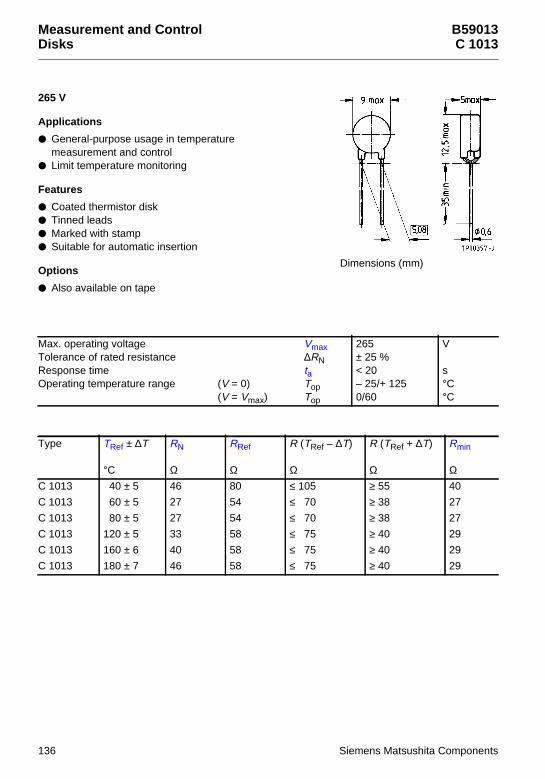
Measurement and ControlDisks
B59013C 1013
265 V
Applications
General-purpose usage in temperaturemeasurement and control
Limit temperature monitoring
Features
Coated thermistor disk Tinned leads Marked with stamp Suitable for automatic insertion
Options
Also available on tape
Max. operating voltage VmaxTolerance of rated resistance ∆RNResponse time taOperating temperature range (V = 0) Top
(V = Vmax) Top
265± 25 %< 20– 25/+ 1250/60
V
s°C°C
Type TRef ± ∆T
°C
RN
Ω
RRef
Ω
R (TRef – ∆T)
Ω
R (TRef + ∆T)
Ω
Rmin
ΩC 1013 40 ± 5 46 80 ≤ 105 ≥ 55 40
C 1013 60 ± 5 27 54 ≤ 70 ≥ 38 27
C 1013 80 ± 5 27 54 ≤ 70 ≥ 38 27
C 1013 120 ± 5 33 58 ≤ 75 ≥ 40 29
C 1013 160 ± 6 40 58 ≤ 75 ≥ 40 29
C 1013 180 ± 7 46 58 ≤ 75 ≥ 40 29
Dimensions (mm)
136 Siemens Matsushita Components

B59013C 1013
Characteristics (typical)
PTC resistance RPTC versus PTC temperature TPTC(measured at low signal voltage)
Type Imax
A
TRmin
°C
TPTC
°C
R (TPTC)
Ω
Ordering code
C 1013 1 0 115 ≥ 4 k B59013-C1040-A70
C 1013 1 20 120 ≥ 4 k B59013-C1060-A70
C 1013 1 40 135 ≥ 4 k B59013-C1080-A70
C 1013 1 80 175 ≥ 4 k B59013-C1120-A70
C 1013 1 120 200 ≥ 4 k B59013-C1160-A70
C 1013 1 140 220 ≥ 4 k B59013-C1180-A70
Siemens Matsushita Components 137

Measurement and ControlDisks
B59008C 8
30 V
Applications
Sensor for small measuring points Limit temperature monitoring
Features
Coated thermistor disk Tinned leads Marked with coded nominal
threshold temperature Characteristics for nominal threshold temperatures
of 90 to 160 °C conform with DIN 44 081 Extremely fast response due to small dimensions
1) VPTC ≤ 2,5 V2) VPTC ≤ 7,5 V
Max. operating voltage (TA = 0 … 40 °C) VmaxMax. measuring voltage (TA – 25 K … TNAT + 15 K) VMeas,maxRated resistance (VPTC ≤ 2,5 V) RNResponse time taOperating temperature range(V = 0) Top
(V = Vmax) Top
307,5≤ 250< 3– 25/+ 1250/40
VVΩs°C°C
Type/Stampcode
TNAT ± ∆T
°C
R1)(TNAT – ∆T)Ω
R1)(TNAT + ∆T)Ω
R 2)(TNAT + 15 K)Ω
R1)(TNAT + 23 K)Ω
Ordering code
C 8 f 60 ± 5 ≤ 570 ≥ 570 — ≥ 4 k B59008-C60-A40
C 8 g 70 ± 5 ≤ 570 ≥ 570 — ≥ 4 k B59008-C70-A40
C 8 h 80 ± 5 ≤ 570 ≥ 570 — ≥ 4 k B59008-C80-A40
C 8 i 90 ± 5 ≤ 550 ≥ 1330 ≥ 4 k — B59008-C90-A40
C 8 j 100 ± 5 ≤ 550 ≥ 1330 ≥ 4 k — B59008-C100-A40
C 8 k 110 ± 5 ≤ 550 ≥ 1330 ≥ 4 k — B59008-C110-A40
C 8 l 120 ± 5 ≤ 550 ≥ 1330 ≥ 4 k — B59008-C120-A40
C 8 m 130 ± 5 ≤ 550 ≥ 1330 ≥ 4 k — B59008-C130-A40
C 8 n 140 ± 5 ≤ 550 ≥ 1330 ≥ 4 k — B59008-C140-A40
C 8 o 145 ± 5 ≤ 550 ≥ 1330 ≥ 4 k — B59008-C145-A40
C 8 p 150 ± 5 ≤ 550 ≥ 1330 ≥ 4 k — B59008-C150-A40
C 8 r 155 ± 5 ≤ 550 ≥ 1330 ≥ 4 k — B59008-C155-A40
C 8 s 160 ± 5 ≤ 550 ≥ 1330 ≥ 4 k — B59008-C160-A40
C 8 t 170 ± 7 ≤ 570 ≥ 570 — ≥ 4 k B59008-C170-A40
C 8 u 180 ± 7 ≤ 570 ≥ 570 — ≥ 4 k B59008-C180-A40
Dimensions (mm)
138 Siemens Matsushita Components

B59008C 8
Characteristics (typical)
PTC resistance RPTC versus PTC temperature TPTC(measured at low signal voltage)
PTC resistance RPTC versus PTC temperature TPTC(measured at low signal voltage)
Siemens Matsushita Components 139

Measurement and ControlDisks
B59100C 100
30 V
Applications
Sensor for small measuring points Limit temperature monitoring
Features
Coated thermistor disk Tinned leads Manufacturer’s logo and type designation
stamped on in white Characteristics for nominal threshold temperatures
of 90 to 160 °C conform with DIN 44 081 Also available on tape
1) VPTC ≤ 2,5 V2) VPTC ≤ 7,5 V
Max. operating voltage (TA = 0 … 40 °C) VmaxMax. measuring voltage (TA – 25 K … TNAT + 15 K) VMeas,maxRated resistance (VPTC ≤ 2,5 V) RNResponse time taOperating temperature range(V = 0) Top
(V = Vmax) Top
307,5≤ 100< 5– 25/+ 1250/40
VVΩs°C°C
Type TNAT ± ∆T
°C
R1)(TNAT – ∆T)Ω
R1)(TNAT + ∆T)Ω
R 2)(TNAT + 15 K)Ω
R1)(TNAT + 23 K)Ω
Ordering code
C 100 60 ± 5 ≤ 570 ≥ 570 — ≥ 10 k B59100-C60-A70
C 100 70 ± 5 ≤ 570 ≥ 570 — ≥ 10 k B59100-C70-A70
C 100 80 ± 5 ≤ 570 ≥ 570 — ≥ 10 k B59100-C80-A70
C 100 90 ± 5 ≤ 550 ≥ 1330 ≥ 4 k — B59100-C90-A70
C 100 100 ± 5 ≤ 550 ≥ 1330 ≥ 4 k — B59100-C100-A70
C 100 110 ± 5 ≤ 550 ≥ 1330 ≥ 4 k — B59100-C110-A70
C 100 120 ± 5 ≤ 550 ≥ 1330 ≥ 4 k — B59100-C120-A70
C 100 130 ± 5 ≤ 550 ≥ 1330 ≥ 4 k — B59100-C130-A70
C 100 140 ± 5 ≤ 550 ≥ 1330 ≥ 4 k — B59100-C140-A70
C 100 145 ± 5 ≤ 550 ≥ 1330 ≥ 4 k — B59100-C145-A70
C 100 150 ± 5 ≤ 550 ≥ 1330 ≥ 4 k — B59100-C150-A70
C 100 155 ± 5 ≤ 550 ≥ 1330 ≥ 4 k — B59100-C155-A70
C 100 160 ± 5 ≤ 550 ≥ 1330 ≥ 4 k — B59100-C160-A70
C 100 170 ± 6 ≤ 550 ≥ 1330 ≥ 4 k — B59100-C170-A70
C 100 180 ± 6 ≤ 550 ≥ 1330 ≥ 4 k — B59100-C180-A70
Dimensions (mm)
140 Siemens Matsushita Components
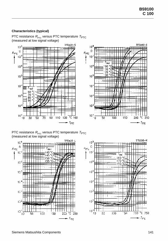
B59100C 100
Characteristics (typical)
PTC resistance RPTC versus PTC temperature TPTC(measured at low signal voltage)
PTC resistance RPTC versus PTC temperature TPTC(measured at low signal voltage)
Siemens Matsushita Components 141

Measurement and ControlProbe Assemblies
B59401D 401
20 V
Applications
Limit temperature sensor in screw-type case
Features
Insulated screw-type metal case,thread M4
Tinned leads Color-coded sealing with black dot Case permits good thermal coupling
Max. operating voltage VmaxTolerance of rated resistance ∆RNInsulation test voltage VisResponse time taOperating temperature range(V = 0) Top
(V = Vmax) Top
20+ 50/– 25 %3< 50– 25/+ 1250/60
V
kV acs°C°C
Type TRef ± ∆T
°C
RN
Ω
RRef
Ω
R (TRef – ∆T)
Ω
R (TRef + ∆T)
Ω
Rmin
ΩD 401 40 ± 5 130 230 ≤ 350 ≥ 170 115
D 401 60 ± 5 80 160 ≤ 240 ≥ 120 80
D 401 80 ± 5 80 152 ≤ 230 ≥ 110 76
D 401 90 ± 5 80 152 ≤ 230 ≥ 110 76
D 401 120 ± 5 80 148 ≤ 225 ≥ 105 74
Dimensions (mm)
142 Siemens Matsushita Components

B59401D 401
Characteristics (typical)
PTC resistance RPTC versus PTC temperature TPTC(measured at low signal voltage)
Type Imax
mA
TRmin
°C
TPTC
°C
R (TPTC)
Ω
Colorof sealing
Ordering code
D 401 175 – 10 95 ≥ 100 k blue B59401-D40-A40
D 401 270 20 110 ≥ 100 k violet B59401-D60-A40
D 401 270 40 125 ≥ 100 k orange B59401-D80-A40
D 401 270 50 130 ≥ 100 k clear B59401-D90-A40
D 401 270 80 155 ≥ 100 k green B59401-D120-A40
Siemens Matsushita Components 143

Measurement and ControlProbe Assemblies
B59801D 801
30 V
Applications
Limit temperature sensor
Features
Insulated screw-type metal case Thread M3 Tinned leads Marked with nominal threshold temperature
and type designation Characteristics for nominal threshold temperatures
of 90 to 160 °C conform with DIN 44 081 Fast response due to small dimensions
1) VPTC ≤ 2,5 V2) VPTC ≤ 7,5 V
Max. operating voltage (TA = 0 … 40 °C) VmaxMax. measuring voltage (TA – 25 K … TNAT + 15 K) VMeas,maxRated resistance (VPTC ≤ 2,5 V) RNInsulation test voltage VisResponse time (TNAT – 20 K … TNAT + 15 K)taOperating temperature range(V = 0) Top
(V = Vmax) Top
307,5≤ 1001,5< 20– 25/+ 1250/40
VVΩkV acs°C°C
Type TNAT ± ∆T
°C
R1)(TNAT – ∆T)Ω
R1)(TNAT + ∆T)Ω
R2)(TNAT + 15 K)Ω
R1)(TNAT + 23 K)Ω
Ordering code
D 801 60 ± 5 ≤ 570 ≥ 570 — ≥ 10 k B59801-D60-A70
D 801 70 ± 5 ≤ 570 ≥ 570 — ≥ 10 k B59801-D70-A70
D 801 80 ± 5 ≤ 570 ≥ 570 — ≥ 10 k B59801-D80-A70
D 801 90 ± 5 ≤ 550 ≥ 1330 ≥ 4 k — B59801-D90-A70
D 801 100 ± 5 ≤ 550 ≥ 1330 ≥ 4 k — B59801-D100-A70
D 801 110 ± 5 ≤ 550 ≥ 1330 ≥ 4 k — B59801-D110-A70
D 801 120 ± 5 ≤ 550 ≥ 1330 ≥ 4 k — B59801-D120-A70
D 801 130 ± 5 ≤ 550 ≥ 1330 ≥ 4 k — B59801-D130-A70
D 801 140 ± 5 ≤ 550 ≥ 1330 ≥ 4 k — B59801-D140-A70
D 801 145 ± 5 ≤ 550 ≥ 1330 ≥ 4 k — B59801-D145-A70
D 801 150 ± 5 ≤ 550 ≥ 1330 ≥ 4 k — B59801-D150-A70
D 801 155 ± 5 ≤ 550 ≥ 1330 ≥ 4 k — B59801-D155-A70
D 801 160 ± 5 ≤ 550 ≥ 1330 ≥ 4 k — B59801-D160-A70
Dimensions (mm)
144 Siemens Matsushita Components

B59801D 801
Characteristics (typical)
PTC resistance RPTC versus PTC temperature TPTC(measured at low signal voltage)
PTC resistance RPTC versus PTC temperature TPTC(measured at low signal voltage)
Siemens Matsushita Components 145

Measurement and ControlProbe Assemblies
B59901D 901
30 V
Applications
Limit temperature sensor
Features
Sensor with epoxy resin coating Tinned leads Metal tag for easy mounting Characteristics for nominal threshold temperatures
of 90 to 160 °C conform with DIN 44 081 Metal tag permits good thermal coupling and
thus short response times
1) VPTC ≤ 2,5 V2) VPTC ≤ 7,5 V
Max. operating voltage (TA = 0 … 40 °C) VmaxMax. measuring voltage (TA – 25 K … TNAT + 15 K) VMeas,maxRated resistance (VPTC ≤ 2,5 V) RNResponse time taOperating temperature range(V = 0) Top
(V = Vmax) Top
307,5≤ 100< 20– 25/+ 1250/40
VVΩs°C°C
Type/Stampcode
TNAT± ∆T
°C
R1)(TNAT – ∆T)
Ω
R1)(TNAT + ∆T)
Ω
R 2)(TNAT + 15 K)
Ω
R1)(TNAT + 23 K)
Ω
Ordering code
D 901 331 60 ± 5 ≤ 570 ≥ 570 — ≥ 10 k B59901-D60-A40
D 901 341 70 ± 5 ≤ 570 ≥ 570 — ≥ 10 k B59901-D70-A40
D 901 351 80 ± 5 ≤ 570 ≥ 570 — ≥ 10 k B59901-D80-A40
D 901 361 90 ± 5 ≤ 550 ≥ 1330 ≥ 4 k — B59901-D90-A40
D 901 371 100 ± 5 ≤ 550 ≥ 1330 ≥ 4 k — B59901-D100-A40
D 901 381 110 ± 5 ≤ 550 ≥ 1330 ≥ 4 k — B59901-D110-A40
D 901 391 120 ± 5 ≤ 550 ≥ 1330 ≥ 4 k — B59901-D120-A40
D 901 401 130 ± 5 ≤ 550 ≥ 1330 ≥ 4 k — B59901-D130-A40
D 901 411 140 ± 5 ≤ 550 ≥ 1330 ≥ 4 k — B59901-D140-A40
Dimensions (mm)
146 Siemens Matsushita Components

B59901D 901
Characteristics (typical)
PTC resistance RPTC versus PTC temperature TPTC(measured at low signal voltage)
PTC resistance RPTC versus PTC temperature TPTC(measured at low signal voltage)
Siemens Matsushita Components 147

Measurement and ControlSMDs
B59701A 1701
25 V
Applications
Limit temperature sensor
Features
Thermistor chip with silver terminations Very small size Fast and reliable response Suitable for reflow soldering,
also for conductive adhesion Suitable for automatic placement Available on 8-mm blister tape
(standard delivery mode)
1) VPTC ≤ 2,5 V2) VPTC ≤ 7,5 V
Max. operating voltage (TA = 0 … 40 °C) VmaxMax. measuring voltage (TA – 25 K … TNAT + 15 K) VMeas,maxRated resistance (VPTC ≤ 2,5 V) RNOperating temperature range(V = 0) Top
(V = Vmax) Top
257,5≤ 1– 25/+ 1250/40
VVkΩ°C°C
Type TNAT ± ∆T
°C
R1)(TNAT – ∆T)kΩ
R1)(TNAT + ∆T)kΩ
R 2)(TNAT + 15 K)kΩ
Ordering code
A 1701 90 ± 5 ≤ 5,5 ≥ 13,3 ≥ 40 B59701-A1090-A62
A 1701 100 ± 5 ≤ 5,5 ≥ 13,3 ≥ 40 B59701-A1100-A62
A 1701 110 ± 5 ≤ 5,5 ≥ 13,3 ≥ 40 B59701-A1110-A62
A 1701 120 ± 5 ≤ 5,5 ≥ 13,3 ≥ 40 B59701-A1120-A62
A 1701 130 ± 5 ≤ 5,5 ≥ 13,3 ≥ 40 B59701-A1130-A62
Dimensions (mm)
Termination
148 Siemens Matsushita Components

B59701A 1701
Characteristics (typical)
PTC resistance RPTC versus PTC temperature TPTC(measured at low signal voltage)
Siemens Matsushita Components 149
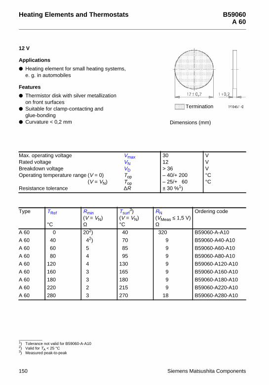
Heating Elements and Thermostats B59060A 60
12 V
Applications
Heating element for small heating systems,e. g. in automobiles
Features
Thermistor disk with silver metallizationon front surfaces
Suitable for clamp-contacting andglue-bonding
Curvature < 0,2 mm
1) Tolerance not valid for B59060-A-A102) Valid for TA < 25 °C3) Measured peak-to-peak
Max. operating voltage VmaxRated voltage VNBreakdown voltage VDOperating temperature range (V = 0) Top
(V = VN) TopResistance tolerance ∆R
3012> 36– 40/+ 200– 25/+ 60± 30 %1)
VVV°C°C
Type TRef
°C
Rmin(V = VN)Ω
Tsurf3)
(V = VN)°C
RN(VMeas ≤ 1,5 V)Ω
Ordering code
A 60 0 202) 40 320 B59060-A-A10
A 60 40 42) 70 9 B59060-A40-A10
A 60 60 5 85 9 B59060-A60-A10
A 60 80 4 95 9 B59060-A80-A10
A 60 120 4 130 9 B59060-A120-A10
A 60 160 3 165 9 B59060-A160-A10
A 60 180 3 180 9 B59060-A180-A10
A 60 220 2 215 9 B59060-A220-A10
A 60 280 3 270 18 B59060-A280-A10
Dimensions (mm)
Termination
150 Siemens Matsushita Components

B59060A 60
Characteristics (typical)
PTC resistance RPTC versus PTC temperature TPTC(measured at low signal voltage)
Siemens Matsushita Components 151

Heating Elements and Thermostats B59042R 1042
12 V
Applications
General-purpose heating element,e. g. for automotive applications
Features
Thermistor plate with aluminum metallization No migration effects For clamp-contacting Max. curvature 0,05 mm
Options
Other dimensions available upon request
1) Valid for TA < 25 °C2) Measured peak-to-peak
Max. operating voltage VmaxRated voltage VNBreakdown voltage VDOperating temperature range (V = 0) Top
(V = VN) TopResistance tolerance ∆R
2012> 40– 40/+ 200– 25/+ 60± 50 %
VVV°C°C
Type TRef
°C
Rmin(V = VN)Ω
Tsurf2)
(V = VN)°C
RN(VMeas ≤ 1,5 V)Ω
Ordering code
R 1042-A40 40 1,001) 75 3,2 B59042-R1040-A10
R 1042-A60 60 1,25 90 3,2 B59042-R1060-A10
R 1042-A80 80 1,00 105 3,2 B59042-R1080-A10
R 1042-A120 120 1,00 145 3,2 B59042-R1120-A10
R 1042-A160 160 0,75 180 3,2 B59042-R1160-A10
R 1042-A180 180 0,75 200 3,2 B59042-R1180-A10
R 1042-A220 220 1,00 230 6,4 B59042-R1220-A10
R 1042-A280 280 1,00 280 12,8 B59042-R1280-A10
Dimensions (mm)
37,2 max
6,4
max
Termination
152 Siemens Matsushita Components

B59042R 1042
Characteristics (typical)
PTC resistance RPTC versus PTC temperature TPTC(measured at low signal voltage)
Siemens Matsushita Components 153

Heating Elements and Thermostats B59053A 53
230 V
Applications
Self-regulating heating element
Features
Thermistor disk with silver metallizationon front surfaces
High electric strength Suitable for clamp-contacting and
glue-bonding Curvature < 0,2 mm
1) Valid for TA < 25 °C2) Measured peak-to-peak
Max. operating voltage VmaxRated voltage VNBreakdown voltage (TA = 25 °C) VDOperating temperature range (V = 0) Top
(V = VN) TopResistance tolerance ∆R
265230500– 40/+ 2000/60± 35 %
VVV°C°C
Type TRef
°C
Rmin(V = VN)Ω
Tsurf2)
(V = VN)°C
RN(VMeas ≤ 1,5 V)Ω
Ordering code
A 53 50 17501) 90 4200 B59053-A50-A10
A 53 70 1400 105 4200 B59053-A70-A10
A 53 90 1200 125 4200 B59053-A90-A10
A 53 110 960 135 4200 B59053-A110-A10
A 53 130 840 155 4200 B59053-A130-A10
A 53 150 700 170 4200 B59053-A150-A10
A 53 180 530 200 4200 B59053-A180-A10
A 53 220 640 235 6000 B59053-A220-A10
A 53 270 530 275 6000 B59053-A270-A10
Dimensions (mm)
Termination
154 Siemens Matsushita Components

B59053A 53
Characteristics (typical)
PTC resistance RPTC versus PTC temperature TPTC(measured at low signal voltage)
Siemens Matsushita Components 155

Heating Elements and Thermostats B59066A 66
230 V
Applications
Self-regulating heating element
Features
Thermistor disk with aluminum metallizationon front surfaces
No migration effects Suitable for clamp-contacting Curvature < 0,2 mm
1) Valid for TA < 25 °C2) Measured peak-to-peak
Max. operating voltage VmaxRated voltage VNOperating temperature range (V = 0) Top
(V = VN) TopResistance tolerance ∆R
265230– 40/+ 2000/60± 35 %
VV°C°C
Type VD
V
TRef
°C
Rmin(V = VN)Ω
Tsurf2)
(V = VN)°C
RN(VMeas ≤ 1,5 V)Ω
Ordering code
A 66 400 50 5001) 100 1200 B59066-A50-A10
A 66 400 70 400 105 1200 B59066-A70-A10
A 66 400 90 345 125 1200 B59066-A90-A10
A 66 400 110 275 140 1200 B59066-A110-A10
A 66 400 130 240 160 1200 B59066-A130-A10
A 66 400 150 200 175 1200 B59066-A150-A10
A 66 400 180 150 200 1200 B59066-A180-A10
A 66 400 220 180 235 1700 B59066-A220-A10
A 66 340 270 150 280 1700 B59066-A270-A10
Dimensions (mm)
Termination
156 Siemens Matsushita Components

B59066A 66
Characteristics (typical)
PTC resistance RPTC versus PTC temperature TPTC(measured at low signal voltage)
Siemens Matsushita Components 157

Heating Elements and Thermostats B59102R 102
230 V
Applications
Self-regulating heating element
Features
Thermistor disk with aluminum metallizationon front surfaces
No migration effects Suitable for clamp-contacting Curvature < 0,05 mm
Options
Other dimensions available upon request
1) Valid for TA < 25 °C2) Measured peak-to-peak
Max. operating voltage VmaxRated voltage VNOperating temperature range (V = 0) Top
(V = VN) TopResistance tolerance ∆R
265230– 40/+ 2000/60± 50 %
VV°C°C
Type VD
V
TRef
°C
Rmin(V = VN)Ω
Tsurf2)
(V = VN)°C
RN(VMeas ≤ 1,5 V)Ω
Ordering code
R 102 400 50 2251) 105 700 B59102-R50-A10
R 102 400 70 180 110 700 B59102-R70-A10
R 102 400 90 155 130 700 B59102-R90-A10
R 102 400 110 125 145 700 B59102-R110-A10
R 102 400 130 105 160 700 B59102-R130-A10
R 102 400 150 90 180 700 B59102-R150-A10
R 102 400 180 66 210 700 B59102-R180-A10
R 102 400 220 80 240 1000 B59102-R220-A10
R 102 400 240 75 255 1000 B59102-R240-A10
R 102 340 270 85 275 1300 B59102-R270-A10
R 102 320 290 78 295 1300 B59102-R290-A10
Dimensions (mm)
37,2 max
6,4
max
Termination
158 Siemens Matsushita Components

B59102R 102
Characteristics (typical)
PTC resistance RPTC versus PTC temperature TPTC(measured at low signal voltage)
PTC resistance RPTC versus PTC temperature TPTC(measured at low signal voltage)
Siemens Matsushita Components 159

Ferrite inductors from SCS stock
Transformationat its best
Not just one-off solutions but com-plete ones designed precisely to arequirements profile are more indemand than ever. So we are offe-ring surface-mount transformers forpower and broadband applicationsstraight from SCS stock:
þ E 6,3 with small dimensions, low leakage inductance and high electric strength
þ ER 11 flat and with low leakage inductance
þ RM 4 LP for high DC biasingþ S interface transformer RM 5
for precise pulse trans-mission in ISDN terminals
þ U interface transformer RM 6
for ISDN applicationsþ Planar inductor RM 7 with high
power density and extremely flat for DC/DC applications
SCS – dependable, fast and competent
Siemens Matsushita ComponentsCOMPONENTS
+S M
SBS-Layout Induktivitäten 01.09.1996 17:59 Uhr Seite 2

Mounting Instructions
Mounting Instructions
1 Soldering
1.1 Leaded PTC thermistors
Leaded PTC thermistors comply with the solderability requirements specified by CECC.
When soldering, care must be taken that the thermistors are not damaged by excessive heat. Thefollowing maximum temperatures, maximum time spans and minimum distances have to beobserved:
Dip soldering Iron solderingBath temperature max. 260 ˚C max. 360 ˚CSoldering time max. 4 s max. 2 sDistance from thermistor min. 6 mm min. 6 mm
Under more severe soldering conditions the resistance may change.
1.2 Leadless PTC thermistors
In case of PTC thermistors without leads, soldering is restricted to devices which are provided witha solderable metallization. The temperature shock caused by the application of hot solder may pro-duce fine cracks in the ceramic, resulting in changes in resistance.
To prevent leaching of the metallization, solder with silver additives or with a low tin content shouldbe used. In addition, soldering methods should be employed which permit short soldering times.
1.3 SMD PTC thermistors
The notes on soldering leadless thermistors also apply to the SMD versions (see IEC 68-2-58).
1.3.1 Wettability test in accordance with IEC 68-2-20
Preconditioning: Immersion into flux F-SW 32.Evaluation criterion: Wetting of soldering areas ≥ 95 %.
Termination Solder Bath temperature (°C) Dwell time (s)
PTC CrNiAg SnPb or SnPbAg60/40 62/36/2
215 ± 3 4
Siemens Matsushita Components 161

Mounting Instructions
1.3.2 Soldering heat resistance test in accordance with IEC 68-2-20
Preconditioning: Immersion into flux F-SW 32.Evaluation criterion: Leaching of side edges ≤ 1/3.
Note:
PTC thermistors in sizes 3225 and 4032 do not have metallized pads, but metal-strip terminations.
1.3.3 Recommended soldering temperature profiles
Vapor phase soldering
Temperature/time diagram for vapor phase soldering, in-line system with preheating. The temper-atures stated refer to the component terminals.
Termination Solder Bath temperature (°C) Dwell time (s)
PTC CrNiAg SnPb or SnPbAg60/40 62/36/2
260 ± 5 10
162 Siemens Matsushita Components

Mounting Instructions
Wave soldering
Temperature on the component terminals during dual wave soldering
Infrared soldering
Temperature on the component terminals during infrared soldering
Siemens Matsushita Components 163

Mounting Instructions
1.3.4 Notes:
– When soldering large components (≥ size1210) care must be taken that the temperature jumpbetween preheating and soldering wave will not exceed 100 K.
– Iron soldering should be avoided, hot air methods are recommended for repair purposes.
2 Conductive adhesion
An alternative to soldering is the gluing of thermistors with conductive adhesives. The benfit of thismethod is that it involves no thermal stress. The adhesives used must be chemically inert.
3 Clamp contacting
Pressure contacting by means of clamps is particularly suitable for applications involving frequentswitching and high turn-on powers. PTC thermistors for heating and motor starting have metallizedsurfaces for clamp contacting.
4 Robustness of terminations
The leads meet the requirements of IEC 68-2-21. They may not be bent closer than 4 mm from thesolder joint on the thermistor body or from the point at which they leave the feed-throughs. Duringbending, any mechanical stress at the outlet of the leads must be removed. The bending radiusshould be at least 0,75 mm.
Tensile strength: Test Ua1:Leads ∅ ≤ 0,5 mm = 5 N
∅ > 0,5 mm = 10 N
Bending strength: Test Ub:Two 90˚-bends in opposite directions at a weight of 0,25 kg.
Torsional strength: Test Uc: severity 2The lead is bent by 90˚ at a distance of 6 to 6,5 mm from the thermistor body.The bending radius of the leads should be approx. 0,75 mm. Two torsions of180˚ each (severity 2).
When subjecting leads to mechanical stress, the following should be observed:
Tensile stress on leads
During mounting and operation tensile forces on the leads are to be avoided.
Bending of leads
Bending of the leads directly on the thermistor body is not permissible.
A lead may be bent at a minimum distance of twice the wire’s diameter + 2 mm from the solder jointon the thermistor body. During bending the wire must be mechanically relieved at its outlet. Thebending radius should be at least 0,75 mm.
Twisting of leads
The twisting (torsion) by 180˚ of a lead bent by 90˚ is permissible at 6 mm from the bottom of thethermistor body.
164 Siemens Matsushita Components

Mounting Instructions
5 Sealing and potting
When thermistors are sealed or potted, there must be no mechanical stress through differing ther-mal expansion in the curing process and during later operation. In the curing process the upper cat-egory temperature of the thermistor must not be exceeded. It is also necessary to ensure that thepotting compound is chemically neutral.
Sealing and potting compounds may reduce the titanate ceramic of PTC thermistors and lead to theformation of low-ohmic conduction bridges. In conjunction with a change in dissipation conditionsdue to the potting compound, local overheating may finally damage the thermistor.
6 Cleaning
If cleaning is necessary, mild cleaning agents such as freon, trichloroethane and perchloroethyleneare recommended. Ultrasonic cleaning methods are permissible.
7 Storage
In order to maintain their solderability, thermistors must be stored in a non-corrosive atmosphere.Humidity, temperature and container materials are critical factors.
If possible, the components should be left in the original packing. Touching the metallization of un-soldered thermistors may change their soldering properties.
Siemens Matsushita Components 165

SCS – dependable, fast and competent
Siemens filters from stock
Siemens Matsushita ComponentsCOMPONENTS
+S M
Ready, steady, go
SCS has 100,000 SIFI filters in stock,ready to go as soon as your orderarrives. We offer a big selectionthrough all the many variants, ie
building-block system, differentattenuation characteristics and packages, various kinds of leads andcurrent ratings from 1 through 20 A.

Quality
Quality
1 Manufacturing process and quality assurance
Quality gate
Incoming goods Inspection of raw materials and parts
Milling Specific surface, grain size
Weighing
Quality gate
Quality gate
Quality gate
Pre-sintering Powder release (vis., mech., el. inspection)
Granulation Humidity, grain size distribution
Pressing Weight, dimensions
Sintering Sinter release (vis., mech., el. inspection)
Metallization Resistance, layer thickness
Grouping by resistance Resistance, B value
Soldering Visual inspection, pull-off strength
Coating, assembly, finish Visual inspection, dimensions
Final measurement Resistance
Conformance test Sampling inspection (mech., el. parameters)
Packing Identity
Warehouse
Tes
ting
and
final
insp
ectio
nP
repr
oduc
tion
Ass
embl
y
Dispatch
Manufacturing process Quality assurance
Siemens Matsushita Components 167

Quality
2 General
S + M has set up extensive quality assurance systems in order to meet the stringent technical de-mands of an open world market. These systems follow the CECC ISO-9000 to ISO-9004 standards.Our QA system received the ISO 9001 certificate in September 1991.
3 Sequence of quality assurance measures
The quality department tested and released the PTC thermistors described in this data book on thebasis of the following criteria: compliance with type specifications, process capability of productionequipment as well as accuracy of measuring and test methods and equipment.
To ensure a constantly high quality level, the following tests are carried out:
3.1 Incoming inspection
The parts and materials required for production are checked for dimensional accuracy and materialproperties in a prescribed sequence.
3.2 Process assurance
To achieve the objective of eliminating defects as efficiently as possible and at their very source,quite different measures are taken. Modern quality tools such as FMEA (Failure Mode and EffectAnalysis) are used already during the starting phase: A risk-priority figure is assigned to potentialdefects according to their significance as well as to the probability of occurrence and detection. Incase of high risk-priority figures, remedial measures are taken from the beginning. During produc-tion all essentail processes are subject to statistical process control (SPC).
3.3 Product assurance
Each manufacturing stage is followed by a socalled “quality control gate”, i.e. the product is onlyreleased for the next stage after passing a corresponding test. The test results are constantly mon-itored and evaluated and are then used to assess the quality of the manufacturing process itself(refer to 3.2).
3.4 Final inspection
During final inspection, specification-based parameters are checked in conformance tests.
4 Delivery quality
The term delivery quality designates the conformance with agreed data at the time of delivery.
168 Siemens Matsushita Components

Quality
5 Sampling inspection
The customer may carry out incoming inspections which are subject to standardized sampling in-spection plans specifying the acceptance or rejection of a delivery lot in conjunction with agreedAQL values (AQL = acceptable quality level).
The scope and the maximum permissible number of defects of a sampling inspection are specifiedin IEC 410 (identical with MIL-STD 105 D and DIN ISO 2859 -1), single sampling plan for normalinspection, inspection level II. The sampling instructions of this standard are such that a deliveredlot will be accepted with a high degree of probability (greater than 90 %), if the percentage of defec-tives does not exceed the specified AQL level.
Generally, the average defect percentage of our deliveries lies clearly below the AQL value. This isensured by appropriate quality assurance measures in the manufacturing plants and substantiatedby the final inspections.
6 Classification of defects
A component is considered defective if it does not comply with the specifications stated in the datasheets or in an agreed delivery specification. Defects which generally exclude the functional use ofthe component (inoperatives) are classified separately from less significant defects.
Inoperatives of thermistors are:
– Short circuit or open circuit– Component, case, terminals or encapsulation broken– Incorrect marking– Mixing of different types
Other defects are:
– Electrical defects (maximum ratings are exceeded)– Mechanical defects, e. g. incorrect dimensions, damaged housings, illegible marking, twisted
leads
7 AQL values
The following AQL values apply to the quoted defects
– for inoperatives (electrical and mechanical) 0,065– for the total number of electrical defectives 0,250– for the total number of mechanical defectives 0,250
The values for the total number of defectives include related inoperatives.
Siemens Matsushita Components 169

Quality
8 Incoming inspection by the customer
The quality of our products is ensured by the QA measures assigned to the individual productionstages as shown on page 167. Thus the customer can do away with cost-intensive incoming in-spections. If a customer wishes nevertheless to carry out an incoming inspection, we recommendthat the inspection plan shown below is used. The inspection methods employed must in this casebe agreed upon between customer and supplier. In many cases a stricter inspection method isagreed upon to the effect that the sample size corresponds to the plan, the required inspection,however, demands “zero defects”, i. e. a lot will only be accepted if the samples are free from de-fects. Regardless of that, all sample tests carried out at S+M are subject to these stricter test con-ditions (zero defects).
The following information is required for the assessment of possible claims: test circuit, sample size,number of defectives found, sample defectives and packing slip, delivery note number, lot numberand/or label.
Sampling plan for normal inspection – inspection level II
in accordance with DIN 40 080 (contents correspond to MIL Std 105 LD and IEC 410)
Columns 2 to 5: Left figure = sample sizeRight figure = permissible defects
Additional condition:
As an acceptance number of 0 and a rejection number of 1 provides only limited information on theactual AQL, the next higher sample size should be taken.
Stichprobeninspection
planN = Lot size
AQL0,065
AQL0,100
AQL0,250
AQL0,400
2 … 50 N N N N or 32-0
51 … 90 N N 50-0 32-0
91 … 150 N N or 125-0 50-0 32-0
151 … 280 N or 200-0 125-0 50-0 32-0
281 … 500 200-0 125-0 50-0 32-0
501 … 1 200 200-0 125-0 50-0 125-1
1 201 … 3 200 200-0 125-0 200-1 125-1
3 201 … 10 000 200-0 125-0 200-1 200-2
10 001 … 35 000 200-0 500-1 315-2 315-3
35 001 … 150 000 800-1 500-1 500-3 500-5
150 001 … 500 000 800-1 800-2 800-5 800-7
> 500 000 1250-2 1250-3 1250-7 1250-10
170 Siemens Matsushita Components

Quality
9 Reliability
We conduct a large variety of endurance trials and environmental tests to assure the reliability ofPTC thermistors. These tests derive from the extremes of expected application conditions, with ex-tra tightening of the conditions so that significant results can be obtained within a reasonableamount of time.
The reliability testing programs of S + M are based on the test plans of relevant CECC standardsfor assessing the quality of electronic components. Environmental tests are conducted according toIEC 68-2 (Electrical Engineering, Basic Environmental Testing Procedures).
S + M performs reliability tests both in qualifying new component families as well as for periodicrequalification. Reliability figures for various component series can be found in the data sheets.
10 Identification and retraceability
On the packaging of all shipped thermistors you will find a bar code label stating type, part number,quantity, date of manufacture and lot number. These details are necessary for speedy and informa-tive handling of returns.
This systematic and unmistakable form of identification means that each component can be tracedto a certain production lot. This in turn permits retracing back through the entire fabrication processas far as raw materials purchasing.
Example:
Lot numberType
Partnumber
Quantity
Date ofmanufacture:YYCWDYY … YearCW … Calendar weekD … Day
e. g. 1 Monday
TAL0052-K
Siemens Matsushita Components 171

Quality
11 Supplementary information
The issuing of quality data – which always relate to a large number of components – is no assuranceof characteristics in a legal sense. But an agreement on such data does not exclude the customer’sright to claim replacement of individual defective PTC thermistors within the terms of delivery. Wecannot assume any further liability, especially for the consequences of component failure.
You should also remember that figures for failure rate refer to an average fabrication situation andare therefore to be understood as mean values (statistical expectations) for a large number of de-livery lots of homogeneous PTC thermistors. They are based on application experience as well ason data derived from preceding inspection under normal or – for the purpose of acceleration – tight-ened conditions.
172 Siemens Matsushita Components

Siemens Matsushita Components 173
Siemens Matsushita Components GmbH & Co. KG (S + M Components for short) is responsible forprotection of the environment in the development, fabrication and use of its products for the intend-ed purpose. S + M Components is very thorough in fulfilling the resulting obligations. Over andabove the legal prescriptions, our guiding principle here is the corporation’s responsibility towardsman and environment.
Responsibility for safety in working with materials that have a potential environmental impact is inthe hands of the various managers. This involves, in the first place, instructing and informing thestaff concerned. A specially trained environmental protection supervisor watches over adherenceto regulations, reports on the introduction of processes within an environmental context and on de-cisions relating to investment (e.g. he checks that all environmentally associated requirements likefilters and sumps have been considered). But advising and informing staff take on the highest pri-ority; this is the only way to ensure that all protective measures are known and observed.
All chemicals employed in development and fabrication are examined for environmental compati-bility or harmful effects before their use on the basis of DIN safety specifications. Alternatives aredevised if risks emerge. The result of this procedure is that today all CFCs as well as all highly toxicmaterials have been eliminated entirely from the fabrication process.
Dust and vapor generated during fabrication are filtered away for disposal. The emission figures ofthe filters are constantly examined; considerable efforts are undertaken to ensure that these figuresare well below the legally prescribed limits. The same applies to the water used in a plant. This be-ing cleansed in a special waste-water treatment process. Water consumption has been reducedsubstantially in recent years through the use of cooling water circuits and water recycling.
Waste produced in the fabrication of components is sorted and collected on the spot and recycledby state-of-the-art methods.
The packaging material used for our components can be fully recycled.
All thermistors can be disposed of on a dump for industrial waste that is similar to household refusewithout any special precautions.
Of course, we are still by no means satisfied with what we have already achieved, and more stepsare due to follow in the interest of further reducing and ultimately eliminating entirely all environmen-tal impact created in the development and fabrication of our components.
Environm
ental Protection M
easuresEnvironmental Protection Measures

SCS – dependable, fast and competent
Ceramic chip capacitors from stock
Siemens Matsushita ComponentsCOMPONENTS
+S M
Small in size, big in performance
Our selection of capacitors rangesfrom standard sizes down to a mini-ature highlight in 0402 style. Mea-suring only 1 x 0.5 x 0.5 mm, it’s anideal solution for applications wherespace is tight, like in handies andcardiac pacemakers. At the sametime all our chips can boast excellentsoldering characteristics, with specialterminal variants for conductive ad-hesion. And we also thought aboutthe right packing for automatic place-ment. You get all sizes down to 1206in bulk case for example, plus voltageratings from 16 to 500 V. By the way,our leaded models have CECCapproval of course, in fact theywere certified more than tenyears ago.
More in the new short form catalog!

Siemens Matsushita Components 175
1 Reliability data
For most measuring PTCs reliability data are given in the data sheets. These data provide informa-tion on the deviation of rated resistance under high thermal, electrical or mechanical stress.
2 Operating temperature range
The permissible operating temperature ranges are specified in the data sheets. Here, a differenceis made between the permissible temperature ranges for loaded and for unloaded PTC thermistors.
For unloaded PTC thermistors the operating temperatures indicated are identical with the surfacetemperature of the device. The operating temperature ranges for V = 0 correspond to the lower cat-egory temperature LCT and the upper category temperature UCT as per CECC 44 000. Under loadthe power dissipation of a PTC thermistor depends on the heat removal conditions. To prevent elec-trical overload the temperature has to be kept within the specified range.
Clim
atic Conditions
Climatic Conditions

SCS – dependable, fast and competent
A whole lot of ring core chokes
Siemens Matsushita ComponentsCOMPONENTS
+S M
Chokes to your choice
You urgently need particular ringcore chokes? That’s no problem, wehave 200,000 pieces in stock anddeliver reliably through SCS. Ourautomated production guarantees
the best of reliability too. It turns outchokes in different versions: flat andupright, with current rated from 0.4to 16 A. UL and VDE approved, andcomplying with the latest EMC stan-dards of course.

Taping and P
ackingTaping and Packing
Many of the components presented in this data book are suitable for processing on automaticinsertion or placement machines. These thermistors can be supplied on tape for easy handling byautomatic systems. The individual modes of taping and packing will be described in the following.
1 Taping of SMD thermistors (in accordance with IEC 286-3)
1) ≤ 0,2 mm over 10 sprocket holes2) Tolerance ± 0,1
Dimension(mm)
Size(8-mm tape)
Size(16-mm tape)
Tolerance
0805 1210 3225 4032
A0 × B0 The rated dimensions of the component compartment have been derived from therelevant component specification and are chosen such that the components cannot
change their orientation within the tape.K0
T2
D0D1
1,501,00
1,50 1,50
+ 0,10 / – 0min.
P0P2P1
4,002,004,00
4,00 2,0012,00
± 0,101)± 0,05± 0,10
W 8,00 16,00 ± 0,30
E 1,75 1,75 ± 0,10
F 3,50 7,502) ± 0,05
G 0,75 0,75 min.
Direction of unreeling
Section A-A
Siemens Matsushita Components 177
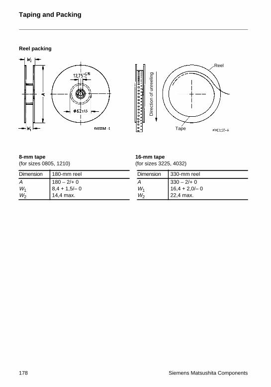
Taping and Packing
Reel packing
8-mm tape 16-mm tape(for sizes 0805, 1210) (for sizes 3225, 4032)
Dimension 180-mm reel Dimension 330-mm reel
AW1W2
180 – 2/+ 08,4 + 1,5/– 014,4 max.
AW1W2
330 – 2/+ 016,4 + 2,0/– 022,4 max.
Dire
ctio
n of
unr
eelin
g
Tape
Reel
178 Siemens Matsushita Components

Taping and Packing
2 Taping of radial-lead PTC thermistors
Dimensions and tolerances (taping in accordance with IEC 286-2)
*) Depends on s
Dimension(mm)
Lead spacing Tolerance ofLS 2,54/5,08
Remarks2,54 mm 5,08 mm
b 11,0 11,5 max.
s 5,0 6,0 max.
d 0,5/0,6 0,5/0,6 ± 0,05
P0 12,7 12,7 ± 0,2 ± 1 mm / 20 sprocket holes
P1 5,08 3,81 ± 0,7
F 2,54 5,08 + 0,6/– 0,1
∆h 0 0 ± 2,0 measured at top of component body
∆p 0 0 ± 1,3
W 18,0 18,0 ± 0,5
W0 5,5 5,5 min. peel-off force ≥ 5 N
W1 9,0 9,0 ± 0,5
W2 2,0 2,0 max.
H 18,0 18,0 + 2,0/– 0
H0 16,0 16,0 ± 0,5
H1 32,2 32,2 max.
D0 4,0 4,0 ± 0,2
t 0,9 0,9 max. without wires
L 11,0 11,0 max.
L1 4,0 4,0 max.
Section A-BDirection of unreeling
Siemens Matsushita Components 179

Taping and Packing
Modes of packing
AMMO packing
Reel packing
Number of pieces: 1000 … 2000
Number of pieces: 1000 … 2000
180 Siemens Matsushita Components

Taping and Packing
Cassette packing
3 Packing codes
The last two digits of the complete ordering code state the packing mode:
40 Bulk50 Radial leads, kinked Tape Cassette packing51 Radial leads, kinked Tape Reel packing52 Radial leads, straight Tape Cassette packing53 Radial leads, straight Tape Reel packing54 Radial leads, kinked Tape AMMO packing55 Radial leads, straight Tape AMMO packing62 SMDs Tape Reel packing70 Radial leads Bulk Cardboard strips
Example: B57164-K102-M UntapedB57164-K102-M52 Taped
Number of pieces: 1000 … 2000
Siemens Matsushita Components 181

SCS – dependable, fast and competent
Disk varistors from stock
Siemens Matsushita ComponentsCOMPONENTS
+S M
In our selection of disk varistorsthere’s something for everything.We offer you application supportand deliver models rated from 11 to 460 V straight from SCSstock. Our product certification likeUL and CECC makes sure your product conforms with CE. All disk varistors are manufactured in Europe, just like our block, strapand SMD varistors.
The choiceis yours

Sym
bols and Term
sSymbols and Terms
A Area
Cth Heat capacity
I Current
Iin/coil Inrush current through degaussing coil
IN Rated current
IK Trip current
Ir Residual currrent
Irms Root-mean-square value of current
IS Switching current
N Number (integer)
P Power
P25 Maximum power at 25 ˚C
Pel Electrical power
PV Dissipation power
Rmin Minimum resistance
RN Rated resistance
∆RN Resistance tolerance
RP Parallel resistance
RPTC PTC resistance
RRef Reference resistance
RS Series resistance
RT Resistance at temperature T (e.g. R25 = resistance at 25 ˚C)
RV Load resistance
T Temperature
t Time
TA Ambient temperature
ta Thermal threshold time
tE Settling time (for level sensors)
TN Rated temperature
TNAT Nominal threshold temperature
Top Operating temperature
TPTC PTC temperature
tR Response time
TRef Reference temperature
TRmin Temperature at minimum resistance
tS Switching time
Tsurf Surface temperature
V or Vel Voltage (with subscript only for distinction from volume)
V Volume
Siemens Matsushita Components 183

Symbols and Terms
Vrms Root-mean-square value of voltage
VD Breakdown voltage
Vis Insulation test voltage
Vmax Maximum operating voltage
VMeas Measuring voltage
VMeas,max Maximum measuring voltage
VN Rated voltage
Vop Operating voltage
VPTC Voltage drop across a PTC thermistor
Vp Pulse strength
α Temperature coefficient
∆ Tolerance, change
δ th Dissipation factor
τa Thermal time constant
τc Thermal cooling time constant
λ Failure rate
Abbreviations / Notes
Surface-mount devices
* To be replaced by a number in ordering codes, type designations etc.
+ To be replaced by a letter
All dimensions are given in mm.
The commas used in numerical values denote decimal points.
184 Siemens Matsushita Components

Subject IndexS
ubject Index
A
ambient temperature 28
B
breakdown voltage VD 24
C
ceramic material 19clamp contacting 40, 164cleaning 165conductive adhesion 164current/voltage characteristic 23
D
decay time 25defects 169degaussing 37directly heated 29
E
energy-saving lamps 35, 36
F
frequency dependence 27fuses 29
G
grain boundaries 19
H
heat dissipation 28heating elements 40
I
impedance 27indirectly heated 29insulation test voltage Vis 25
L
leakage sensing 39level sensors 38limit indication 39
Mmaximum measuring voltage VMeas,max 24maximum operating voltage Vmax 24media 39minimum resistance Rmin 21motor starting 37
Nnominal threshold temperature TNAT 22
Ooperating point 28operating states 30overflow control 38overload protection 29
Ppeak voltage 25potting 165PTC thermistor 19PTC thermistor effect 19PTC volume 31pulse strength VP 25
Qquality assurance 167
Rrated current IN 24rated resistance RN 21rated voltage VN 24reference resistance RRef 21reference temperature TRef 21residual current Ir 24resistance RPTC 22response time tR 25rise time 25robustness of terminations 164
Ssealing 165self-heating 20, 22settling time tE 26soldering 161
Siemens Matsushita Components 185

Subject Index
storage 165surface temperature Tsurf 23switching current IS 24switching time tS 24, 32
Ttelephone line card protection 34temperature coefficient α 22temperature dependence 20temperature sensors 39temperature TPTC 22thermal cooling time constant τc 25thermal threshold time ta 25time delay 35transformer protection 34trip current IK 23, 30trip temperature 39
Vvaristor effect 26voltage dependence 26
Zzero-power characteristics 20zero-power resistance RT 20
186 Siemens Matsushita Components


![14 Dimension Sheets: Upright Gear Units Mounting Position … · Catalog – X.. Series Helical and Bevel-Helical Gear Units 357 14 X.F.. helical gear units [mm] Dimension Sheets:](https://img.pdfslide.net/doc/110x75/5b918f7f09d3f26a278bf43b/14-dimension-sheets-upright-gear-units-mounting-position-catalog-x-series.jpg)