Embed Size (px)
Citation preview

Islamic Republic of Iran
Vice Presidency for Strategic Planning and Supervision
General Technical Specification and Execution Procedures for Transmission
and Subtransmission Networks Control and Automation Systems of
High Voltage Substations
NO: 503- 1
Energy Ministry - Tavanir Co.Power Industry Technical Criteria Project www.tavanir.ir
Office of Deputy for Strategic Supervision Bureau of Technical Execution Systemhttp://tec.mporg.ir


DESCRIPTION
ITEM PAGE Chapter 1- Technical Specification for Conventional Control, Measurement Equipment & Systems 1-1- General requirements ....................................................................................................................3
1-2- Control System .............................................................................................................................3
1-3- Measuring Equipments .................................................................................................................4
1-3-1 General ........................................................................................................................................ 4
1-3-2- Measuring and Indicating Instruments....................................................................................... 4
1-3-2-1- Line Feeder ......................................................................................................................... 5
1-3-2-2- Busbar ................................................................................................................................. 6
1-3-2-3- Power Transformer.............................................................................................................. 6
1-3-2-4- Reactor (if available)........................................................................................................... 7
1-3-2-5- Synchronizing Brackets ...................................................................................................... 7
1-3-3- Power Meters ............................................................................................................................. 8
1-3-3-1- General specifications of measuring center......................................................................... 8
1-3-3-2- Measuring system characteristics........................................................................................ 9
1-4- Annunciator .................................................................................................................................10
1-5- Event Recorder ............................................................................................................................10
1-6- Fault Recorder..............................................................................................................................10
1-7- Fault Locator................................................................................................................................12
1-8- Auto reclosing..............................................................................................................................13
1-8-1- 400 and, 230 kV substations line auto reclosing....................................................................... 13
1-8-2- 132 kVand 63 kV substations line auto reclosing..................................................................... 14
1-9- Synchronizing Equipment............................................................................................................14
1-10- Supervisory Control and Data Acquisition Equipment..............................................................15
1-11- Panels .........................................................................................................................................15
1-11-1- General.................................................................................................................................... 15
1-11-1-1- Relay Protection Panels.................................................................................................... 17
1-11-1-2- Metering Panel ................................................................................................................ 17
1-11-1-3- Fault locator and fault recorder Panel .............................................................................. 17
1-11-1-4- Interface Cubicle .............................................................................................................. 17
1-11-1-5- Control Panels .................................................................................................................. 18
1-11-1-6- Marshalling Cubicles ....................................................................................................... 18
1-11-1-7- Panel Construction and Layout Philosophy .................................................................... 18
1-11-1-8- Panel, wiring and cabling requirements ........................................................................... 19
1-11-2- Control and selector switches ................................................................................................. 20

1-11-3- Push buttons............................................................................................................................ 20
1-11-4- Indicating lamps...................................................................................................................... 20
1-11-5- Position indicators................................................................................................................... 21
1-11-6- Space heaters........................................................................................................................... 21
1-11-7- Interior lighting and socket ..................................................................................................... 21
1-11-8- Colours of Indicator lights and push buttons .......................................................................... 21
1-11-9- Contacts in relays and current switches .................................................................................. 21
1-12- General requirements in electronic equipments.........................................................................22
1-12-1- Racks, apparatus, frames, panels ............................................................................................ 22
1-12-2- Plugs, jacks, switches.............................................................................................................. 22
1-12-3- Conductors, printed circuits .................................................................................................... 22
1-12-4- Components ............................................................................................................................ 22
1-13- Spare parts and tools ..................................................................................................................23
1-14 – Tests .........................................................................................................................................23
1-14-1- Routine tests............................................................................................................................ 23
1-14-2- Type tests ................................................................................................................................ 23
1-15- Drawings & documents .............................................................................................................24
1-15-1- Documents to be given By Tenderer....................................................................................... 24
1-15-2- Documents to be given by Contractor I Supplier.................................................................... 24
Chapter 2- Technical Specification for Distributed Control Systems (DCS)
2-1- General requirements ...................................................................................................................37
2-2- System architecture......................................................................................................................38
2-2-1- Station level controller.............................................................................................................. 38
2-2-2- Bay Control Units ..................................................................................................................... 40
2-2-3- Redundant station level controllers........................................................................................... 41
2-3- Mechanical considerations...........................................................................................................41
2-4- Inspection and tests ......................................................................................................................42
2-4-1- Type tests .................................................................................................................................. 42
2-4-2- Routine tests.............................................................................................................................. 42
2-4-3- Functional and performance tests ............................................................................................. 42
2-4-4- Factory Acceptance Tests (FAT) .............................................................................................. 43
2-4-5- Site tests .............................................................................................................................43
2-5- Training........................................................................................................................................44
2-6- Online Diagnosis and maintenance..............................................................................................44
2-7- Documentation.............................................................................................................................45
2-8- Functional allocating....................................................................................................................45
2-9- Optical fiber .................................................................................................................................47

Technical Specification for Conventional Control, Measurement Equipment & Systems
1
Technical Specification for Conventional
Control, Measurement Equipment & Systems

Technical Specification for Control and Automation Systems of High Voltage Substations
2
Technical Specification for Conventional Control, Measurement Equipment & Systems
3
1-1- General requirements
This specification covers the requirement for design, manufacturing, factory testing, marking and packing of conventional and control equipment and systems. Protection and control equipment shall function satisfactorily and fulfill the requirements of specification and regulations for the conditions as regards to specified climatic factors (e.g. temperature, humidity. air pressure and pollution), mechanical forces & biological activities etc. Protection and control equipment and systems shall be designed, manufactured and tested according to the requirements of the latest edition of the following standards and other equivalent publications: IEC 60050 (301): IEC Vocabulary - General terms on measurements in electricity. IEC 60050 (302): IEC vocabulary - Electrical measuring instruments. IEC 60050 (303): IEC vocabulary - Electronic measuring instruments. IEC 60050 (441): IEC vocabulary - Switchgear, controlgear and fuses. IEC 60051 : Direct acting indicating and analogue electrical measuring instruments and their
accessories. IEC 60255 : Electrical relays. IEC 60258 : Direct acting recording electrical measuring instruments and their accessories. IEC 60337 : Control switches (low voltage switching devices for control and auxiliary circuits,
including contactor relays). IEC 60341 : Push button switches. IEC 60473 : Dimensions for panel mounted indicating and recording electrical measuring
instruments. IEC 60617-7 : Graphical symbols for diagrams - switchgear, controlgear and protective devices. IEC 60617-8 : Graphical symbols for diagrams - Measuring instruments, lamps and signaling devices. IEC 60839 : Alarm systems. All amendments, supplements and reference publications of the above mentioned standards shall also be applied. Control equipment comprises equipment for indication, registration, signaling, protective functions and apparatuses for manual and automatic control and regulation. Rating and characteristics of conventional and control equipment and systems are specified in Schedule (I).
1-2- Control System
The function of a control system is to collect all the information for the operations personnel to supervise the operating conditions of the substation and whenever necessary to initiate changes to operating conditions.

Technical Specification for Control and Automation Systems of High Voltage Substations
4
Data collection and control commands shall be divided in the following items: - Event recording - Fault recording - Fault locating - Monitoring of measured values - Automatic reclosing - Automatic switching to isolate faults - Switching of standby circuits - Switching for system re-arrangement - Syncnronlzing - Sequence switching for maintenance purposes. Each circuit breaker and isolator shall be provided with indication in control room and in local switchyard marshalling boxes. The control room indication can be through respective discrepancy switches. But switchyard marshalling box indication shall be by semaphores. Isolator intermediate position (i-e. not fully open/close) shall be indicated in control panels. Depending upon type of C.B. mechanism various indicating conditions of C.B shall be indicated /annunciated in control room. A mimic diagram is generally required in order to show the actual operating position at the substation, and the indicating instruments should be mounted in the control panel. The mimic shall be designed as a mosaic panel.
1-3- Measuring Equipments
1-3-1 General
The function of the measuring equipment is to indicate and record (wherever required) the electrical quantities of current, voltage, frequency, active and reactive power, active and reactive energy. All measurements in control room and remote measurements shall include with transducer. The total measurement error in a measuring chain shall not exceed 3% of the entire measuring range. This includes errors from measured value transducers, transmitters, measuring instrument and data processing equipment. Normally the errors from the measured value transducer and transmitter together shall not exceed ±1%.
1-3-2- Measuring and Indicating Instruments
Operational supervision shall take place by means of indicating instrument. These instruments shall normally be located on the control panels related to each object, the ammeters, voltmeters, megawatt meters and megavar meters shall be located in the control panel. The recording voltmeters and recording frequency meter shall be mounted in busbar control panels.

Technical Specification for Conventional Control, Measurement Equipment & Systems
5
Watt-hour meter and varhour meters shall be 3 phase two element type suitable for the measurement of balanced and unbalance loads in three phase, three wire circuits. They shall be suitable for flush mounting on vertical panels with only flanges projecting outside with back connected terminals. Meters shall have reverse running stop, and direct reading gear wheel type indicator. They shall read kWH, kVARH or MWH, MVARH as the case may be without the use of multiplying factors. The number of digits provided shall be adequate to cover at least 1000 hours of operation at rated conditions. The current coils of the meters shall have a continuous over load capacity of 200%. Also current coils shall withstand 10-times the rated current without loss of accuracy. The meters shall have retransmitting contacts, the impulse rate of which shall be suitable for remote indication or summating system. The summators shall be used at transforming stations and shall be used for both active and reactive energy summations separately. Adequate number of channels shall be provided after due considerations of future extension bays. Each object in the substation shall be provided with indicating, recording, integrating, and metering devices as listed below or else modified by the Engineer in which case the modification of the Engineer shall have priority.
1-3-2-1- Line Feeder
For 63 and 132 kV substations: - Three ammeters - One voltmeter with phase- phase and phase- earth selector switch. - One doublewide type wattmeter and varmeter - One doublewide type watthour meter and varhour meter For 230 and 400 kV substations: - Three ammeters - One voltmeter with phase-phase and phase-earth selector switch. - One double side type wattmeter - One double side type varmeter - One watthour meter for flow out from bus - One watthour meter for flow into bus - One varhour meter for flow out from bus - One varhour meter for flow into bus - One voltmeter for T-off connection voltage measurement in 1.5 CB arrangements.

Technical Specification for Control and Automation Systems of High Voltage Substations
6
1-3-2-2- Busbar
Indicating and recording meters for 63 and 132 kV busbar shall be only one voltmeter. Indicating and recording meters shall be provided on each 400, 230 kV busbar as follows: - One single phase recording frequency meters with 45 to 55 HZ range to be installed on each busbar or
bus section of highest voltage of the substation. - One single phase recording voltmeter should be installed on each busbar or bus section of each voltage
in the substation. - One single phase indicating voltmeter on each busbar or bus section.
1-3-2-3- Power Transformer
• 400 kV, 230 kV substations: Following metering equipment shall be provided on each side of the transformer: a) H.V. side - Three ammeters b) M.V. side (if power is not to be sold on this side) - One ammeter with selector switch - One voltmeter with selector switch for ph-ph and ph-N. - One wattmeter 2 element unbalances type. - One varmeter 2 element unbalances type. c) M.V. side (if power is to be sold on this side) - Three ammeters with max demand indicator (hand reset type) - One voltmeter with selector switch. - One wattmeter, 2 element unbalance type. - One varmeter, 2 element unbalance type. - One set of tariff metering per transformer, the set shall consist of following:
* One watthnur meter, 2 element unbalance power. * One varhour meter, 2 element unbalance power.
- One set of tariff metering for substation. The set shall consist of following. The number of channels shall be suitable for all transformers including future ones.
* One watthour totaliser for export.

Technical Specification for Conventional Control, Measurement Equipment & Systems
7
* One varhour totaliser for export. * One clock tariff switch.
d) L.V. side - One voltmeter with selector switch. • 132 kV, 63 kV substations: Following metering equipment shall be provided on each side of the transformer: a) L.V. side: - Three ammeters - One power factor meter - One tap position indicator - One wattmeter with converter - One varmeter with converter - One watthour meter - One varhour meter b) H.V. side: - Three ammeters
1-3-2-4- Reactor (if available)
- Three ammeters or one ammeter with selector switch. - One single side deflection varmeter. - One voltmeter with selector switch. 1-3-2-5- Capacitor bank (if available) - Three double- side Ammeter - One varmeter
1-3-2-6- Synchronizing Brackets
Swinging brackets containing synchronizing indicating instrument shall be provided for each voltage system for checking before closing the related circuit breaker. These brackets shall be mounted on side/center of the control panels, with swinging facility to enable reading from any circuit breaker control panel in the substation. Each bracket shall consist of following: - One rotary synchronouscope. - One twin pointer voltmeter. - One twin read frequency meter.

Technical Specification for Control and Automation Systems of High Voltage Substations
8
- Two synchronizing lamps - All auxiliary and voltage transformers and other devices.
1-3-3- Power Meters
1-3-3-1- General specifications of measuring center
The measuring device shall be a digital 3 phase measuring center with 2 wattmeters. This device shall capable to meter the energy in both directions and 4 phasor quadrant. The specifications and capabilities of measuring center shall be as following:
- 3 phase, 2 wattmeter measuring center with capability of energy metering in two direction and four phasor quadrant.
- 1A current input, 0.001A minimum sensing current with 2 times of nominal current overload for long times and 25 times of nominal current withstand for 4 seconds and 1 second withstand for 50 times of nominal current overload.
- 5A current input, 0.005A minimum sensing current with 2 times of nominal current overload for long times and 25 times withstand for 2 seconds and 50 times withstand for 1 second.
- Input voltage range between 100-110V, thermal capacity up to 1.5 times of nominal voltage for long times and up to 2 times of nominal voltage for 10 seconds - capability of CT, PT factors configuration - voltage, current, power factor measurement for all phases, also one phase and 3 phase
measurement of W,Var,VA,Wh,Varh,VAh - true rms value measurement - 0.2 percent resolution of voltage, current, W,Wh metering - 1 percent resolution of reactive energy metering - Power factor metering with 0.5% resolution and frequency with 0.1% resolution. - Capability of time and date setting and synchronization via GPS - Memorized for saving the measuring data according to user requirement - Supply voltage range between 85- 230 VAC or 40-160 VDC - Backup battery with 10 years life time in normal operation and 1 year without supply - Temperature range between -25 to 65 °C - Maximum humidity 95% for 30 unsuccessive day of one year - Communication interface to information network, hardware and software facilities for data
transmission - Capability of setting, test, reading of data by software locally

Technical Specification for Conventional Control, Measurement Equipment & Systems
9
- Capability of setting, test, reading of measured data by software form remote control center - Compatibility of test results with guarantee table and standard - Capability of test and normal mode operation recognition
1-3-3-2- Measuring system characteristics
• Record of events parameters and alarms - Recording capability of energy in the form of numerical and trends - Recording capability of required parameters for 4 month with 5 min. period and change the
time period setting and parameter setting facility - Capability of remaining the data and settings in the case of power failure - Recording of active and reactive energy in 1 hour period for 4 month - Min. max. values recording with time tagging - Transient recording in each phase with time tagging - Logging of latest configuration time or latest data reading time - All settings and configuration shall be saved in device memory
• Measuring and recording of power quality parameters: - Voltage and current harmonics measurement up to 22th harmonic - Voltage and current THD value measurement - Recording of harmonic distortion with time tagging and duration
• Communication specifications of measuring center: - Time synchronization with GPS system via standard port - Equipped with RS232, RS485 ports - Inferred port - Compatible with MODBUS, RTU, DNP3, TCP protocols - Optical port for data reading and communication with computer or other terminals to configure
parameters of system • Inputs, outputs of measuring center:
- 4 configurable digital input - 4 configurable digital output - configurable pulse input - configurable pulse output

Technical Specification for Control and Automation Systems of High Voltage Substations
10
- configurable analogue output
1-4- Annunciator
The annunciator shall be mounted on related feeder control panel and consists of fault indication and audible alarm systems. When a fault has occurred, the audible alarm shall be initiated at the same time as the fault indication. The indication of fault and alarm shall be capable of starting regardless of any earlier fault indications at other points and regardless of whether these have been acknowledged. Sequence of operation of the annunciator shall be as follows:
Annunciator condition
Fault contact Audible alarm
Visual indication
Normal Abnormal
Sound cancel Acknowledge
Reset Lamp test
Open Close
Close or Open Close or Open
Open Open
Off On Off Off Off Off
Off Flashing Flashing
Steady on Off
Steady on
The annunciators shall be suitable for operation with normally open fault contacts which close on a fault. Annunciators shall be suitable for accepting fleeting faults of duration not less than 5 milli seconds. The Contractor in agreement with engineer, shall prepare list of points to be annunciated in each substation.
1-5- Event Recorder
The event recorder is a supervisory system which quickly submits relevant information concerning the condition of the plant in chronological order. With good resolution and accurate time marking, the events which are recorded on the signal sequence recorder shall be used for analysis. The event recorder shall be equipped with a buffer memory for storing timed signal changes. Date and time of occurrence shall be recorded in the event recorder with seconds. The substation event recorder shall be furnished with specified DC voltage. The contractor in agreement with Engineer shall prepare the list of point to be recorded in each substation.
1-6- Fault Recorder
The fault recorder equipment shall provide permanent records for subsequent analysis of the system voltage and current waveforms and the time sequence of operation of the various protective equipment of the protected object. The presentation shall take place in the form of a recorded output of all relevant signals, together with the time of occurrence. Fault recorder shall be provided with electrical timing system from the instant it is started and record shall commence from about 0.5 seconds before fault detection and continue about 5 seconds regardless of the duration of the short circuit of starring contacts. Built in memory shall be provided such that all the signals/events which occurred 0.5 seconds before the fault detection shall be recorded without loss of signal information.

Technical Specification for Conventional Control, Measurement Equipment & Systems
11
Recorder shall have self checking feature and shall be unaffected by harmonics and switching transients and also shall have zoom feature for a closer look. The fault recorder shall have enough AC channels which record continuously variable parameters and also enough digit channels. The fault recorder shall be provided with time and data marker. The number of the instrument, date, hour, minute, anti seconds at whom the recording begins shall be shown on the chart. Operation of the fault recorder shall not be affected by interference from other circuits. Suitable alarm shall be provided to signal "approaching end of the paper". To make the fault recorder fully operational with the feeder CWs. CTs, protection equipments and substation supply voltage, all necessary equipments and accessories shall be supplied. Following quantities shall generally be recorded in the substations: A- Analogue channels (AC quantities):
- Line feeder: Three phase voltages and currents, neutral current - Power transformer: Neutral voltage and current of HV side - Reactors: Neutral voltage and current
B- Event markings (DC quantities) - Trip initiation from various SUB-I and SUB-II or main and backup protective relays of every
respective equipment (individual relay contacts) separately. - Individual lock out relay/tripping relay operation for every separately. - Distance relay starting elements for lines separately. - Carrier sends and receives signals for lines separately. - Reclosing commands for lines. - C.B. Trip - C.B. Fail
C- Analogue channels (DC quantities) - Circuit breaker tripping coil 1 trip current of circuit breaker (each pole). - Circuit breaker tripping coil 2 trip current of circuit breaker (each pole). - Circuit breaker closing coil current of circuit breaker.
The fault recorder shall be started by impulse from all of protective relay contacts and from fault detector relay contacts and also shall be started by detecting voltage and current level. The fault recorder shall be powered from a station battery common to all other protective equipment. If required, for correct time marking, signal generator should be supplied by contractor.

Technical Specification for Control and Automation Systems of High Voltage Substations
12
1-7- Fault Locator
The fault locator shall determine the location of the fault with the highest possible accuracy even under conditions of successful auto reclose. A fault locator shall measure and store the necessary values, before the associated circuit breaker opens. But on the other hand must wait a start signal given by the trip command of the protective relays. The fault locator shall be designed to perform satisfactorily at site network conditions rather than laboratory conditions i.e. harmonic free values, stable transient free conditions, defined over current and voltage drops etc. The fault locator shall be suitable for any distance relay. The fault locator equipment shall be provided with various features to prevent its maloperation and reading errors. Followings are a few/most important errors to be considered: - Errors due to the inductive coupling from parallel lines. - Errors due to high fault resistance, high earth resistance. - Errors due to series capacitances. - Errors due to compensating reactors - Errors due to transient performance of CT and CVT, harmonics and DC component at current and
voltage. - Double end fed earth faults when there is phase angle difference between both end currents. The fault distance shall on a indicated in digital form either in percent or in km and shall be presented by two digits on display. Binary coded digital remote transmission shall be employed. The equipment shall incorporate a memory, so that reading will be available for a reasonable period of time after the occurrence of the fault. The reading shall be possible of at least two measured values in rapid succession (e.g in the event of unsuccessful reclosing) and the accuracy of the fault locator shall be within the limits of 3% of line length although the remanence flux present in the CT core could be most unfavorable during successive auto reclosers.

Technical Specification for Conventional Control, Measurement Equipment & Systems
13
The start of fault locator shall take place when line protections (distance and earth fault) operates for a fault and trips the CB. The microprocessor based calculations shall take place on the measuring values prior to and during the fault. These data shall be stored in a memory in the fault locator and calculation shall be made after tripping of breaker. The relay shall be complete with test switches, power supply unit, setting unit, output unit, mounting and connections and all other accessories for correct and complete operation. The calculation method shall not be influenced by: - Fault current infeed from line remote end. - Line loading prior to fault. - Magnitude of fault resistance.
1-8- Auto reclosing
1-8-1- 400 and, 230 kV substations line auto reclosing
The high speed transmission line protections. e.g. distance, shall be initiating the auto reclosing. Also the auto reclosing shall be blocked under permanent fault conditions, stub protections, limiting conditions of the circuit breakers, carrier system not available or testing, reverse side HV equipment faults, breaker failure tripping, pole discordance tripping, shunt reactor protective relays and any other devices which are necessary to block the auto reclosing. The A.R. scheme shall provide a hand reset lock out for permanent line faults and it shall not be possible to reclose the CBs once it is decided that the fault is not of transient nature. For lines which are connected in 1.5 CB arrangement, the auto reclosing schemes shall be as per type LT or LL. Type LT is primarily for 1.5 CB bay having one line and one transformer shall be reclosed for line feeder faults and be blocked for the transformer faults. Type LL is for 1.5 CB bay having two lines in each bay in which middle CB shall be required to auto reclose for both line faults. The scheme shall provide following manual modes of selection for sequence of operation:
- Non auto three phase trip and lockout for any fault - Single phase trip and reclose for single phase initial fault. Three phase trip and lockout for any fault
in reclaim time and for two or three phase initial fault - Three phase trip and reclose for any initial fault. Three phase trip and lock out for any fault in reclaim
time - Single phase trip and reclose for single phase initial fault. Three phase trip and recluse for two or
three phase initial fault. Three phase trip and lockout for any fault in reclaim time - Single phase trip and reclose for single phase initial fault. Three phase trip and reclose for two or
three phase initial fault or any fault in reclaim time. Three phase trip and lockout for any fault in reclaim time following three phase auto recluse
The circuit breaker close pulse from the auto recloser shall be provided for definite time say of order of 200 msec.
Technical Specification for Control and Automation Systems of High Voltage Substations
14
Special features shall be provided to ensure that only one close pulse shall be given at the end of each dead time. Adequate number and type of contacts etc. shall be provided in all types of auto recloser schemes to block required directional earth fault relays from maloperation during the dead time of single phase auto recloser. Proper coordination with respective earth fault relays shall be done in this regard by the contractor. The scheme monitors shall be provided to lockout the scheme if it has not completed its cycle by the end of preset time (e.g. due to necessary line/bus voltage conditions not being present to permit reclosing). The scheme monitor timer shall have long range to accumulate maximum dead time plus maximum reclaim time setting.
1-8-2- 132 kVand 63 kV substations line auto reclosing
The A.R. scheme shall provide a hand reset lock out for permanent line faults. The circuit breaker close pulse from the auto recloser shall be provided for definite time say of order of 200 msec. special features shall be provided to ensure that only one close pulse shall be given at the end of each dead time. Adequate number and type of contacts shall be provided in all types of auto recloser schemes to block required relays from mal-operation. The scheme monitors shall be provided to lockout the scheme if it has not completed its cycle by the end of preset time. The scheme monitor timer shall have long range to accumulate maximum dead time plus maximum reclaim time setting.
1-9- Synchronizing Equipment
The synchronizing equipment shall be used for local and remote closure of the circuit breaker. The following circuit connections are required: - Voltage selection for choosing the transmission line, transformer, reactor and busbar voltage. - Calling circuits for the ordered synchronizing function from the control panel, remote control and
automatic equipment. - Indicating circuit. - Breaker closing circuit. - Connection of automatic equipment for synchronizing. Switching - in units shall be used for connecting the voltages to be synchronized to the synchronizing unit. The individual switching - in units shall be connected so that only one circuit breaker at a time can be synchronized (only one synchronizing unit is provided for the whole of the substation). All breaker closures from the control panel, remote control equipment, automatic control panel, remote control equipment and automatic reclosing of transmission lines shall take place automatically via the synchronizing equipment.
Technical Specification for Conventional Control, Measurement Equipment & Systems
15
For all measured voltages, isolated transformer shall be included in the synchronizing equipment. Provision shall be made for manual switching of the synchronizing voltages to the equipment consisting of a double voltmeter, synchroscope and double frequency meter, placed on the control panel when the synchronizing equipment is inoperative due to an internal fault or adverse operating conditions. Selectors and terminals shall be provided for testing. The selector shall also serve as an isolating switch. The measured voltages shall be connected across follower relays controlled from the auxiliary contacts of the breakers and isolators. The follower relays shall be supervised, and synchronizing equipment blocked in cases of discrepancy. The synchronizing guard relay scheme which allows that the C.B. can be closed only when first Synchronizing check relay is closed, shall be provided. The guard relay shall allow to close the C.B. only when check synchronizing relay closes first, gives an indication and closing impulse in given late, thereby providing firm guarantee that both machine and man give closing impulse and not man or machine alone. In order to permit the C.B. to be closed on live-line, dead-bus and dead-line, live-bus conditions without directional preference, the voltage check relays shall be provided for all C.B. closing schemes.
1-10- Supervisory Control and Data Acquisition Equipment
Supervision and control of the power network is to be effected from National Electric Power Dispatch System (NEPDS) and Supervisory Control and Date Acquisition (SCADA) equipment. All necessary connections, controls and indications, auxiliary relays etc. shall be provided according to TAVANIR standard for substations interface with dispatching systems.
1-11- Panels
1-11-1- General
All panels for relays, energy meters, fault and event recorders, fault locators and interface cubicle shall be constructed with back door and front glass. All panels, boards and boxes shall be completely metal enclosed and shall be dust, moisture and vermin proof. Panels shall be free standing, floor mounting type and shall comprise frames enclosed completely with rolled sheet steel with thickness not less than 2 mm. The doors can readily be opened and closed and the wiring will be allocated sufficient space to be clearly and neatly arranged. Adequate cooling in the cubicles shall primarily be arranged by natural circulation. It is essential that the design of the panels/equipment with natural cooling takes into account the fire risk which can exist. Flame retardant materials shall be used, and particular attention shall be paid to the layout and segregation of the equipment. Also packing density of equipment shall deliberately be reduced to ensure that the temperature rise is acceptable and hence reduced fire hazard.

Technical Specification for Control and Automation Systems of High Voltage Substations
16
All doors and removable covers shall be gasketed all around with neoprene gaskets. Ventilating louvers, if provided, shall have screens and tilters. The screen shall be of fine wire mesh of brass. Galvanized steel wire meshes are not acceptable. All equipment on front of panel shall be mounted flush or semiflush. In case of semiflush mounting, only flange or bezel shall be visible from the front. For all relative protection panels, external door with viewing glasses, in addition to equipment frame shall be provided. The number of items of equipment grouped in every cubicle shall be such that the various units readily be replaced and have adequate cooling. Terminal and wiring markings shall be clearly visible. All panels shall be fitted with earthing terminals of connection by copper conductor with a cross-sectional area at leas 50 sq.mm to earthing system of the substation. The panels shall be equipped with suitable devices for connecting the cable shields. The devices shall be arranged so that the connection to the cable shield will be as short as possible. In addition, the panels door shall be connected to main body by means of braided copper conductors. The panels shall be equipped with intense lightning with switches and with wall sockets. The supply shall be run to terminals to allow for connection to the lighting network of the station. All sheet steel work shall be painted in accordance with relevant standards, approved by engineer. The colors as per RAL standard shall be as follows: Control panels : RAL 7035 Relay panels : RAL 7035 Interface panels : RAL 7035 Junction cubicles and Boxes : RAL 7038 Fire fighting panel : RAL 3020 The colours for the various voltages in the mimic diagram shall be as follows:
System Voltage Mimic colour 400 kV Brown 230 kV Red 132 kV Green 63 kV Blue
Conductors shall have the necessary area and construction with regard to load and mechanical strength. The panel wiring to be carried out with 1000/600V grade, single core with flame, vermin & rodent proof PVC insulation. Conductors in control panel shall consist of extra multistrand single copper conductors terminated with terminal lugs. The conductor panels and protection panels, for CT & CVT circuit shall be extra multistrand single copper, conductor with following min cross - sectional areas: -For busbar protection - 4mm2,CU -For all other protection - 2.5mm2,CU - For control commands -2.5mm2,CU
Technical Specification for Conventional Control, Measurement Equipment & Systems
17
-For metering/recording - 2.5mm2,CU -For SCADA circuits- 2.5mm2,CU -For all CVT Circuits - 4mm2,CU -For CT circuits - 4 mm2,CU
1-11-1-1- Relay Protection Panels
A relay protection panel shall generally be arranged for object only. However, object protection which is more modest in extent may employ a common cubicle for several objects. When a common cubicle is utilized for several objects, the objects should be clearly separated.
1-11-1-2- Metering Panel
This panel shall be consisted of energy meters. Generally, one panel shall be provided for two Feeders. The following meters shall be considered fix each feeder: - One MWH meter for input power. - One MVARH meter for input power - One MWH meter for output power - One MVARH meter for output power For the selection of energy meters and metering panels, the power market instruction shall be considered.
1-11-1-3- Fault locator and fault recorder Panel
This panel shall be consisted for FL and FR equipments. The FL and FR equipments of all feeders may be installed on common panel. If the panel does not have sufficient space for installing the equipments, all fault recorders can be installed in one panel, and fault locators shall be installed in line protection panels.
1-11-1-4- Interface Cubicle
The interface cubicle represents a link between the control and protection equipment in the control building and the SCADA. In the interface cubicles isolation shall be provided between circuits. Interface cubicles, as required, accommodate equipment such as: control relay, indicating relays, the necessary follower relays, blocking relays, and measured value transducers. The panels shall he installed in control room and in the nearest position to SCADA room.
1-11-1-5- Control Panels
The mimic diagram shall provide a simple and clear representation of the plant, showing the interconnections between the objects. Also, the LVAC and LVDC system shall be shown as a part of mimic diagram. The mimic diagram shall agree with the operating and station diagrams and shall also agree as close as possible with the layout of substation. The mimic diagram shall be shown as an interconnected diagram. The control panel shall be designed as a mosaic panel.

Technical Specification for Control and Automation Systems of High Voltage Substations
18
1-11-1-6- Marshalling Cubicles
Outdoor marshalling cubicles should contain terminal blocks, the necessary connecting devices. Internal connections, nameplates instruction plates, auxiliary relays, switches and various items of equipment which is necessary of its respective systems.
1-11-1-7- Panel Construction and Layout Philosophy
Following basic requirements that exist for construction and layout of all panels, and particularly protection and control panels in the substation, shall be provided and engineer's approval shall be obtained against each clause. - Protection against the environment both climatic and electrical - Facilities to simplify maintenance and repairs - Flexibility to allow future extensions and modifications - Reliability in service - Minimum space requirements - Ease of installation on site From panel layout and segregation point of view, the contractor shall design the scheme with essentially required criteria: - It must be possible to take out of service and work safely on the equipment for an individual primary
circuit without the risk of interfering with operation of other primary circuit. - Provision shall be made for easy installation of equipment. - It must be possible to disconnect the auxiliary supplies to the equipment associated with each individual
primary circuit independently. - Clear segregation of terminal wiring for each primary circuit shall be provided to avoid errors. - An outage of any part of the system must be acceptable for the time required to repair or replace that
part and restore it to service. - Fault to any one equipment must not affect the continuous operation of other primary circuit. This
requirement is also applicable to each protective system where duplicate (SUB-I and SUB-II or main and backup) protection systems are provided for one circuit.
Consequently, the grouping shall be done on a primary circuit basic for the equipment necessary to maintain each circuit in operation. The equipment concerned are: - Local control of switchgear associated with individual primary circuits. - Circuit protections where duplicate protection is installed, it shall be necessary to provide segregation
between each system. This will also apply to the wiring for CTs, PTs, trip coils, DC distribution, etc. - Auto reclosing and synchronizing check. - Fault locators - Fault recorders - Remote control - Circuit backup protections.

Technical Specification for Conventional Control, Measurement Equipment & Systems
19
- Circuit breaker fail protection. - Interlocking, auxiliary schemes command, metering, signaling, annunciations and supervision etc. - Individual automatic controls (e-g. reactor and capacitor controls). Various other systems and components shall usually be grouped together on substation basis according to function. Engineer's approval in such cases is required.
1-11-1-8- Panel, wiring and cabling requirements
All cubicles shall contain mounting devices for equipment, wirings, cables, and etc. All external wires shall be connected to terminal block and shall be capable of being isolated individually. Only one wire shall be connected to any terminal. Terminal blocks, wires and cables shall be numbered in such a manner that testing and fault tracing will be facilitated. Clamps shall be provided for connecting cables. Engraved core identification plastic ferrules, marked to correspond with panel wiring diagram shall be fitted at both ends of each wire. Ferrules shall fit tightly on the wire and shall nor tall off when the wire is disconnected from terminal block. The wire numbers shown on the wiring diagram shall he in accordance with relevant standards. All wires directly connected to trip circuit of breaker of device shall be distinguished by the addition of a red coloured unlettered ferrule. The panel wring shall be done with multi-colour wires as follows: DC control circuits general : Grey Trip circuits : Red AC circuits : Black along with red, yellow, blue and black ferrules CT and VT circuits : Red, yellow, blue and black (N) Earthing : Green-yellow All other connections : Grey
All necessary cable terminating accessories such as cable glands, gland plates having suitable holes for specific cables, packing glands, clamps, and etc. for cable shall be provided. Terminal blocks for CT and VT secondary leads shall be provided with special test links. CT secondary leads shall be provided with short circuiting and earthing facilities by the use of CT short circuiting switch. 415/240 V circuit terminals shall be segregated from other terminals and fitted with non-inflammable transparent plastic covers to prevent contact with any live parts and to be separated from DC circuits. At least 10% spare terminals shall be provided on each panel and these spare terminals shall be uniformly distributed on all terminal blocks.

Technical Specification for Control and Automation Systems of High Voltage Substations
20
1-11-2- Control and selector switches
Control and selector switches shall be rotary type with enclose contacts and provided with escutcheon plates clearly marked to show operating position and suitable for semiflush mounting with only the switch front plate and operating handle projected out. Circuit breaker and isolator control switches shall be three positions, spring return to normal type and shall have external red and green indicating amps for indicating "close" and "open" positions. Alternatively, "discrepancy type" control switches with built- in-pilot lamps may be provided. The lamp shall glow steady when the control switch position and breaker position correspond and shall flash when there is disagreement between the two positions. Also it shall be required to press the switch before turning to close or trip command positions. Contacts of the switches shall be spring assisted and contact faces shall be with rivets of pure silver. Springs shall not be used as current carrying parts.
1-11-3- Push buttons
Push buttons shall be of momentary contact type. All push buttons shall have 2 NO and 2 NC contacts. The contacts shall be able to make and carry 5 A at 250 V DC and 6 A at 415 V AC and shall be capable of breaking 1 A inductive load at 250 V DC. Illuminated type push buttons shall generally not be used.
1-11-4- Indicating lamps
Indicating lamps shall be provided with series connected resistors of adequate thermal capacity. Lamps shall have translucent covers to diffuse lights and coloured red, green, orange, clear white and blue as specified below: Red : Energized or situation which requires immediate action. Green : Unexercised or indication of safe situation. Orange : Caution on abnormal condition. White : Any specific meaning not covered in Red, Green and Orange. Blue : Any meaning, may be used whenever doubt exists. Bulbs and lenses shall he interchangeable and easily replaceable from the front of the panel.
1-11-5- Position indicators
Position indicators of "Semaphore" type shall be provided where specified in scheduled as part of the mimic busbars on panels for indicating the position of circuit breakers, isolators, etc. The indicator shall be suitable for semi-flush mounting with only the front disc protecting out and with terminal connections from the rear when the supply to the indicator fails, the pointer shall take up an intermediate position to indicate the supply failure.

Technical Specification for Conventional Control, Measurement Equipment & Systems
21
Semaphore indicators for isolator position indication, shall be so mounted in the mimic that isolator closed position shall complete the continuity of the mimic. The mimic indication of all LVAC and LVDC circuits shall be provided on control panel.
1-11-6- Space heaters
Strip type space heaters of adequate capacity shall be provided inside each panel and boards to prevent moisture condensation on the wiring and panel mounted equipment when the panel is not in operation. Space heaters shall be rated for 230 V, single phase, 50 HZ, AC supply. Heaters shall be provided with rotary type ON-OFF isolating switches and suitable protection.
1-11-7- Interior lighting and socket
Each panel shall be provided with a suitable lighting fixture rated for 230 V, single phase, 50 HZ, AC supply for the interior illumination of the panels. The fitting shall be complete with protection unit and the switching of the fitting shall be controlled by the respective panel door switch. Each panel shall he provided with a 230 V, single phase, 50 HZ, 5 Amps. 3 pin industrial socket with switch. The socket with switch shall be mounted inside the panels at a convenient location for connection of hand lamps. Each panel shall equipped with a telephone socket that installed in suitable location.
1-11-8- Colours of Indicator lights and push buttons
In general, the colour of indicator lights (transmitted light), flashing light, and push-buttons shall be as per IEC 60073. The colour of an indication light or a push-button shall be chosen with regard to the information to be given by the light to the operator. The indicating light (transmitted light) shall be diffused light type. The steady light shall normally be used for indication where as flashing light shall be used in areas which either require further distinction or information or additional emphasis. Flashing light shall be used for following function: - To attract further attention. - To request immediate attention. - To indicate discrepancy between command state and actual state of related equipment.
1-11-9- Contacts in relays and current switches
Contacts shall have sufficient contact rating with regard to the circuit they serve in, calculated for the life time of the plant or guaranteed number of operations by the contractor whichever is most stringent. Contacts in operating switches, limit switches, auxiliary relays, auxiliary contacts on item of equipment etc both for DC and AC, directly included in the operation, indication and tripping circuits of the installation, shall have a making, conducting and breaking capacity of at least 0.4A at 110 VDC and L/R=40ms, calculated for the life time of the installation or guaranteed number of operations by the contractor whichever is more stringent.

Technical Specification for Control and Automation Systems of High Voltage Substations
22
1-12- General requirements in electronic equipments
1-12-1- Racks, apparatus, frames, panels
Racks, apparatus, frames and panels shall be constructed in accordance with IEC standards. Equipment shall be modulized in easily replaceable units of the plug-in type. If current circuits pass through such plug devices, they shall be short circuited when the apparatus is withdrawn.
1-12-2- Plugs, jacks, switches
Plugs, jacks, switches and other contact function shall be mechanically stable and have sufficient contact pressure, all contact parts including screws shall be manufactured and surface-processed in such a way that they are suited to the currents and voltages which they are to be exposed to, and withstand the necessary disassembly for normal apparatus maintenance, and that harmful corrosion occurs. Plugs and jacks shall be non-reversible. Locking devices shall be provided to hinder contacts from separation unintentionally.
1-12-3- Conductors, printed circuits
Conductors shall have such an area, no. of strands, insulation and flexibility that maintenance and repairs or apparatuses can be performed without damaging the conductors and that voltage drop and conductors heating are not abnormally high. Each conductor shall have minimum 3 strands. Solid conductors are not acceptable. Printed-circuit cards shall be in accordance with IEC 60249 and 60326. The nominal thickness of the laminate shall be 1.6mm and the minimum thickness of the copper foil 0.035mm. The laminate shall be of uninflammable material.
1-12-4- Components
Components shall be standard design available from several manufacturers. They shall be clearly labeled, according to their relevant location in the equipment. In diagrams and in other lists, they shall be easily identifiable by means of their normal trade designations. Components shall not be loaded with more that 80% of their ratings. Replacement shall be possible without damaging or moving other components.
1-13- Spare parts and tools
The Manufacturer's recommended spare parts for 5 years trouble free operation and any special tools deemed necessary for erection, operation and repair shall be provided.
Technical Specification for Conventional Control, Measurement Equipment & Systems
23
1-14 - Tests
All relay protection shall be capable of being tested individually (even during normal operation) with adequate safety of the test personnel and without the risk of spurious tripping. The purpose of the tests and inspection is to provide confirmation that the equipment has been designed, manufactured and assembled in accordance with the standards technical specification and that the equipment operates in the intended manner. Electrical tests and inspection shall be carried out at the manufacturer works prior to delivery of the equipment. Tests shall be carried out in accordance with IEC Standard or other valid standards where IEC is not applicable. Equipment shall be subjected to manufacturing routine tests and inspection. A few or every type of equipment shall normally be subjected to type testing. Type tests shall be carried out according to the relevant IEC. If type tests (verified by certificate) are already carried out, new tests are not generally necessary. The tests shall be carried out under operational conditions of the site. Panels and its equipment and secondary wiring shall be subjected to routine tests.
1-14-1- Routine tests
- Visual inspection - Check of the accuracy and measurement range. - Mechanical operation test. - Verification of degree of protection. - High voltage test (2000 volts for 1 minute) - Electrical controls, interlocks, sequential and functional operation tests. - Verification of wiring as per approved schematic drawing.
1-14-2- Type tests
Type rests shall be carried out in the manufacturer's works on each type of control system. During the tests, auxiliary equipment shall be erected and connected so as to reproduce service conditions as closely as possible.
1-15- Drawings & documents
1-15-1- Documents to be given By Tenderer
- Filled schedules (II). - Catalogue and technical pamphlets.

Technical Specification for Control and Automation Systems of High Voltage Substations
24
- Outline drawing. - Summary of type test reports. - Detailed summary of exceptions to tender specifications - Reference list. - List of spare parts.
1-15-2- Documents to be Given by Contractor I Supplier
The electrical and mechanical design, fabrication, factory testing, working and packing, transportation, erection, site test, operation and maintenance drawings, documents and manuals shall be submitted not limited to the following: - Calculation sheets to establish adequacy of equipment in any respect. - Technical literature and brochures for panels, devices, apparatus, and etc . - Functional block diagrams for control, metering and protection systems. - Functional block diagrams for each equipment. - CVT and CT specifications and requirements. - Internal elementary and function block diagrams of protective equipments. - Wiring & cabling diagrams and tables. - Test reports and certification of compliance. - Warehousing, operating and maintenance instruction manuals. - Site tests instruction manuals. - List of components. - Routine test certificates. - Type test documents. - Drawings list. - Packing, transportation, operation, installation and storage instruction manuals.

Technical Specification for Conventional Control, Measurement Equipment & Systems
25
SCHEDULE (I) RATING AND CHARACTERISTICS OF CONVENTIONAL CONTROL, MEASUREMENT AND
RECORDING EQUIPRENT& SYSTEMS ITEM DESCRIPTION TECHNICAL PARTICULARS
1 Particulars of system 1-1 Nominal system voltage kV 63/132/230/400 1-2 Highest system voltage kV 72.5/145/245/420 1-3 Number of phases 3 1-4 Nominal system frequency HZ 50 1-5 System neutral earthing effectively earthed/ non effectively 1-6 Max. duration of short time current 1-3 1-7 Applicable standard IEC 1-8 Rated current in secondary circuit A 1-5 1-9 Rated voltage in secondary circuit (PH-PH) V 100-110
1-10 Rated auxiliary DC voltage V * 1-11 Permissible variation of DC voltage and class -20 to +10% 1-12 Fault level kA *
2 Service condition 2-1 Altitude above sea level m 1000/1500/2000/2500 2-2 Ground seismic acceleration m/s2 0.2g/0.25g/0.3g/0.35g 3 Single and three phase auto- reclosing equipment:
3-1 Speed/type of the auto-reclosing scheme: 3-1-1 High speed Yes/No Yes 3-1-2 Slow speed Yes/No No 3-1-3 Slow and high speed Yes/No Yes 3-2 Number of atuo-reclosing shots (one or two) two 3-3 Manual close inhibit time 3 to 5 sec. 3-4 Whether hand reset lockout feature on permanent trip
required? Yes/No Yes 3-5 C.B. closing pulse time sec 0.2 to 0.3 sec 3-6 Single- phase trip pulse time sec 0 to 0.4 sec 3-7 Three-phase trip pulse time sec 0 to 0.4 sec 3-8 Whether heavy duty contacts with magnetic blow out
required for closing C.B? Yes/No Yes 3-9 Operation indicator Yes/No Yes
3-10 Operation counter Yes/No Yes

Technical Specification for Control and Automation Systems of High Voltage Substations
26
SCHEDULE (I) RATING AND CHARACTERISTICS OF CONVENTIONAL CONTROL, MEASUREMENT AND
RECORDING EQUIPRENT& SYSTEMS ITEM DESCRIPTION TECHNICAL PARTICULARS 3-11 Whether features for annunciation of C.B maintenance
after preset number of A/R scheme operation is required? Yes/No Yes
3-12 Method of reclosing: 3-12-1 Single phase (SPAR) Yes/No * 3-12-2 Three phase (TPAR) Yes/No * 3-12-3 Single or three phase (SPAR or TPAR) Yes/No * 3-12-4 Single and three phase (SPAR and TPAR) Yes/No * 3-13 Whether provision is provided for blocking and
Switching- in the A/R equipment from:
3-13-1 Control relay panel Yes/No Yes 3-13-2 Remote control Yes/No Yes 3-14 Whether equipment to individually monitor following
features is required for each C.B? 3-14-1 Synchronising check Yes/No Yes 3-14-2 Live line/dead bus Yes/No Yes 3-14-3 Live bus/dead line Yes/No Yes 3-15 Fault locator:
3-15-1 Current transformer ratio * 3-15-2 Voltage transformer ratio * 3-15-3 Phase selection feature Yes/No Yes 3-15-4 Measuring time msec 30 3-15-5 Calculating time sec 60 3-15-6 Distance setting range 0-999.9 ohm/ph 3-15-7 Operating range:
3-15-7-1 Current: 0.1-20 times of In 3-15-7-2 Voltage 0.01-1.5 times of Un 3-15-8 Consistency in measurement +30% of setting
4 Control, relay and other associated indoor/outdoor panels
4-1 Type of sheet steel 4-2 Thickness of sheet steel:
4-2-1 Front mm 2 4-2-2 Rear mm 2 4-2-3 Sides mm 2

Technical Specification for Conventional Control, Measurement Equipment & Systems
27
SCHEDULE (I) RATING AND CHARACTERISTICS OF CONVENTIONAL CONTROL, MEASUREMENT AND
RECORDING EQUIPRENT& SYSTEMS ITEM DESCRIPTION TECHNICAL PARTICULARS
4-3 Type of panels required: 4-3-1 Control panels Yes/No Yes 4-3-2 Relay panels Yes/No Yes 4-3-3 Energy meter panels Yes/No Yes 4-3-4 Fault recorder/ locator panels Yes/No Yes 4-3-5 Event recorder panels Yes/No Yes 4-3-6 Interface panels for and scada Yes/No Yes 4-3-7 Outdoor marshalling boxes Yes/No Yes
5 Measurement equipment 5-1 Accuracy class index
5-1-1 Active and reactive power % ±0.5 5-1-2 Voltage % ±0.2 5-1-3 Current % ±0.2 5-1-4 Frequency % ±0.2 5-2 Nominal input voltage V 230 VAC 5-3 Self supply Yes/No Yes (optional) 5-4 Nominal frequency Hz 50 5-5 Nominal input current A 1 or 5 5-6 Auxiliary power supply 230 VAC/110VDC 5-7 Protection degree (IP) Front: IP54 rear: IP20 6 Indication equipment
6-1 Annunciator: 6-1-1 Whether urgent and non-urgent alarm discrimination
required:
6-1-1-1 Audible alarm Yes/No Yes 6-1-1-2 Visible alarm Yes/No Yes

Technical Specification for Control and Automation Systems of High Voltage Substations
28
SCHEDULE (I) RATING AND CHARACTERISTICS OF CONVENTIONAL CONTROL, MEASUREMENT AND
RECORDING EQUIPRENT& SYSTEMS ITEM DESCRIPTION TECHNICAL PARTICULARS 6-1-2 Type of audible alarm for:
6-1-2-1 Urgent alarm hooter 6-1-2-2 Non urgent alarm bell 6-1-3 Number of lamps in each annunciator window 2 6-1-4 Type of reset (manual/self) manual 6-2 Event recorder:
6-2-1 Number of channels * 6-2-2 Individual recording channels for each event input is
required? Yes/No Yes 6-2-3 Method of recording for indication:
6-2-3-1 Function In the form of line 6-2-3-2 Time In the form of location
6-3 Fault recorder: 6-3-1 Total number of recording channels :
6-3-1-1 Total number of analog channels * 6-3-1-2 Total number of contact channels * 6-3-2 Number of analog channels per feeder * 6-3-3 Number of contact channels per feeder * 6-3-4 Totals number of channels used per feeder * 6-3-5 Number of current recorder channels per feeder phase
current
* 6-3-6 Number of voltage recorder channels per feeder phase
voltage
* 6-3-7 Duration of timing for which the recorder shall be reading
after the appearance of fault sec 5 6-3-8 Duration of timing for which the recorder shall be reading
before the appearance of fault sec 0.5 6-3-9 Date, time (hour, minute & second) marker required? Yes/No Yes
6-3-10 End of paper alarm contact required? Yes/No Yes 6-3-11 Recorder" In operation" indication required? Yes/No Yes
* The parameters value is defined by designer.

Technical Specification for Conventional Control, Measurement Equipment & Systems
29
SCHEDULE (II) GUARANTEED THCHNICAL INFORMATION OF CONVENTIONAL CONTROL, MEASUREMENT & RECORDING
EQUIPMENT & SYSTEMS (TO BE SUPPLEID WITH TENDER)
ITEM DESCRIPTION TECHNICAL PARTICULARS 1 General
1-1 Manufacturer's name and country 1-2 Manufacturer's type & designation 1-3 Rated frequency HZ 1-4 Rated current in secondary circuit A 1-5 Rated voltage in secondary circuit V 1-6 Permitted Max. ambient temperature °C 1-7 Permitted Min. ambient temperature °C 1-8 Permitted Max. average humidity % 1-9 Rated auxiliary DC voltage V
1-10 Permissible variation of DC voltage and class 2 Single & three phase auto –reclosing equipment
2-1 Power consumption in the DC circuit W 2-2 Category of auto - reclose scheme 2-3 Speed type of the autoreclosing scheme:
2-3-1 High speed Yes/No 2-3-2 Slow speed Yes/No 2-3-3 High and slow Yes/No 2-4 Method of reclosing:
2-4-1 Single phase (SPAR) Yes/No 2-4-2 Three phase (TPAR) Yes/No 2-4-3 Single or three phase (SPAR or TPAR) Yes/No 2-4-4 Single & three phase (SPAR and TPAR) Yes/No 2-5 Number of auto - reclosing shots (1 or 2) 2-6 Manual close inhibit time sec 2-7 Whether complete AR scheme logic is as per the
requirements of the specification (if no, state deviations)? Yes/No 2-8 Various starting and blocking features as per
specification provided (if no, state detailed reasons)? Yes/No 2-9 Whether provision is provided for blocking and initiation
the AR equipment from:

Technical Specification for Control and Automation Systems of High Voltage Substations
30
SCHEDULE (II) GUARANTEED THCHNICAL INFORMATION OF CONVENTIONAL CONTROL, MEASUREMENT
& RECORDING EQUIPMENT & SYSTEMS (TO BE SUPPLEID WITH TENDER)
ITEM DESCRIPTION TECHNICAL PARTICULARS 2-9-1 Control / relay panel Yes/No 2-9-2 Remote control Yes/No 2-10 Whether hand reset lockout feature on permanent
trip provided? Yes/No 2-11 Range of dead time adjustments
2-11-1 SPAR sec 2-11-2 TPAR sec 2-11-3 SPAR or TPAR sec 2-11-4 SPAR and TPAR sec 2-12 Range of reclaim time adjustment sec 2-13 Range of A/R scheme lockout timer sec 2-14 Auto recluse cycling time for:
2-14-1 SPAR sec 2-14-2 TPAR sec 2-15 CB closing pulse time sec 2-16 Single phase trip pulse time sec 2-17 Three phase trip pulse time sec 2-18 Whether equipment to individually monitor
following features provided for each CB:
2-18-1 Synchronizing check Yes/No 2-18-2 Live line /dead bus Yes/No 2-18-3 Live bus/dead line Yes/No 2-19 Whether heavy duty contacts with magnetic
blow out provided for closing CB? Yes/No 2-20 Hand reset operation indicator with inscription
provided? Yes/No 2-21 Operation counter provided? Yes/No 2-22 Whether features for annunciation of "CB
maintenance" after preset number of A/R scheme operation provided? Yes/No
2-23 Type of mounting 3 Control, relay and other associated /
indoor/outdoor panels
3-1 Type of steel sheet 3-2 Thickness of sheet steel:
3-2-1 Front mm 3-2-2 Rear mm 3-2-3 Sides mm
Technical Specification for Conventional Control, Measurement Equipment & Systems
31
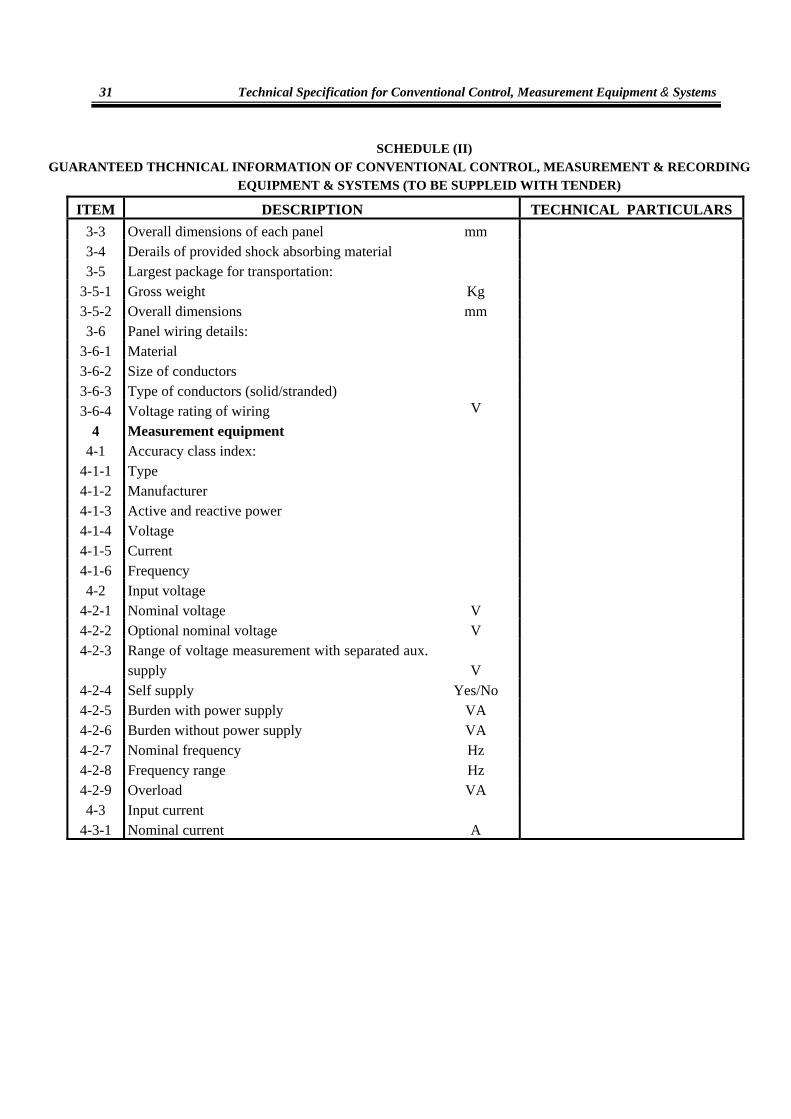
SCHEDULE (II) GUARANTEED THCHNICAL INFORMATION OF CONVENTIONAL CONTROL, MEASUREMENT & RECORDING
EQUIPMENT & SYSTEMS (TO BE SUPPLEID WITH TENDER)
ITEM DESCRIPTION TECHNICAL PARTICULARS 3-3 Overall dimensions of each panel mm 3-4 Derails of provided shock absorbing material 3-5 Largest package for transportation:
3-5-1 Gross weight Kg 3-5-2 Overall dimensions mm 3-6 Panel wiring details:
3-6-1 Material 3-6-2 Size of conductors 3-6-3 Type of conductors (solid/stranded) 3-6-4 Voltage rating of wiring V
4 Measurement equipment 4-1 Accuracy class index:
4-1-1 Type 4-1-2 Manufacturer 4-1-3 Active and reactive power 4-1-4 Voltage 4-1-5 Current 4-1-6 Frequency 4-2 Input voltage
4-2-1 Nominal voltage V 4-2-2 Optional nominal voltage V 4-2-3 Range of voltage measurement with separated aux.
supply V 4-2-4 Self supply Yes/No 4-2-5 Burden with power supply VA 4-2-6 Burden without power supply VA 4-2-7 Nominal frequency Hz 4-2-8 Frequency range Hz 4-2-9 Overload VA 4-3 Input current
4-3-1 Nominal current A

Technical Specification for Control and Automation Systems of High Voltage Substations
32
SCHEDULE (II) GUARANTEED THCHNICAL INFORMATION OF CONVENTIONAL CONTROL, MEASUREMENT & RECORDING
EQUIPMENT & SYSTEMS (TO BE SUPPLEID WITH TENDER)
ITEM DESCRIPTION TECHNICAL PARTICULARS 4-3-2 Burden VA 4-3-3 Overload VA 4-4 Auxiliary power supply:
4-4-1 Aux. voltage V 4-4-2 Optional Aux. voltage V 4-4-3 Power supply voltage range V 4-4-4 Burden VA 4-4-5 Overload VA 4-5 Display
4-5-1 LCD Yes/No 4-5-2 Number of digits 4-6 Relay outputs
4-6-1 Contact capacity W 4-6-2 Maximum switching capacity W 4-6-3 Maximum number of pulses 4-6-4 Pulse duration ms 4-7 Design
4-7-1 Protection class 4-7-2 Weight kg 4-8 Environmental conditions:
4-8-1 Temperature °C 4-8-2 Range of operation °C 4-8-3 Humidity %
5 Indication equipment 5-1 Annunciator :
5-1-1 Dimensions of each window 5-1-2 Lamps:

Technical Specification for Conventional Control, Measurement Equipment & Systems
33
SCHEDULE (II) GUARANTEED THCHNICAL INFORMATION OF CONVENTIONAL CONTROL, MEASUREMENT & RECORDING
EQUIPMENT & SYSTEMS (TO BE SUPPLEID WITH TENDER)
ITEM DESCRIPTION TECHNICAL PARTICULARS5-1-2-1 Voltage V 5-1-2-2 power W 5-1-3 Minimum duration of impulse for initiating contact 5-1-4 Type of reset 5-1-5 Urgent and non urgent alarm Yes/No 5-1-6 Different colour of visible alarm Yes/No 5-2 Event recorder:
5-2-1 Number of contact channels 5-2-2 Individual record channel for each event input is provided? Yes/No 5-2-3 Whether chronology in event printer provided? Yes/no 5-2-4 Duration of chronology msec 5-2-5 Whether digital display provided? Yes/No 5-2-6 Operation characteristics details:
5-2-6-1 Acquisition: Input Event resolution time msec Sequential memory (printing)
5-2-6-2 Signal processing: Digital processing time msec Urgency of level for:
• Non-urgent alarms • Signal data • Optional data • Signaling state printing at the end of event provided? Yes/No 5-2-6-3 Possibility for manual recording of: All inputs All inputs which are at 0 status All inputs which are at 1 status Every selected input

Technical Specification for Control and Automation Systems of High Voltage Substations
34
SCHEDULE (II) GUARANTEED THCHNICAL INFORMATION OF CONVENTIONAL CONTROL, MEASUREMENT & RECORDING
EQUIPMENT & SYSTEMS (TO BE SUPPLEID WITH TENDER)
ITEM DESCRIPTION TECHNICAL PARTICULARS 5-2-6-4 Genera1 power supply:
Rated voltage and tolerance V Consumption VA Supervision for failure
5-2-6-5 Details of dating features: Date /time information
Accuracy Synchronizable
5-2-7 Self testing periodically triggered? Yes/No 5-2-8 Operator testing feature provided? Yes/No 5-2-9 Mounting details 5-3 Fault recoder:
5-3-1 Number of oscillographic traces 5-3-2 Number of time marker traces 5-3-3 Speed of paper cm/sec 5-3-4 Maximum deflection of oscillographic traces cm 5-3-5 Time interval recorded before starting of the recorder sec 5-3-6 Time interval recorded after starting the recoder sec 5-3-7 VA consumption per oscillographic voltage trace
element VA
5-3-8 Rated value of the current channel A 5-3-9 Rated value of the voltage channel V
5-3-10 Max. inputs with specified accuracy: 5-3-10-1 Current A 5-3-10-2 Voltage V 5-3-11 Permissible over voltage:
5-3-11-1 Continuously V 5-3-11-2 During 1 second V 5-3-12 Permissible over current:
5-3-12-1 Continuously A 5-3-12-2 During 1 second A 5-3-13 Power supply :
5-3-13-1 Rated voltage and tolerance V 5-3-13-2 Consumption VA 5-3-13-3 Supervision for failure Yes/No 5-3-14 Mounting position 5-3-15 Recorder in operation indication provided? Yes/No 5-3-16 Self testing Yes/No 5-3-17 Capacity of buffer memory display Yes/No

Technical Specification for Conventional Control, Measurement Equipment & Systems
35
Technical Specification for Distributed Control Systems (DCS)

Technical Specification for Control and Automation Systems of High Voltage Substations
36
Technical Specification for Distributed Control Systems (DCS)
37
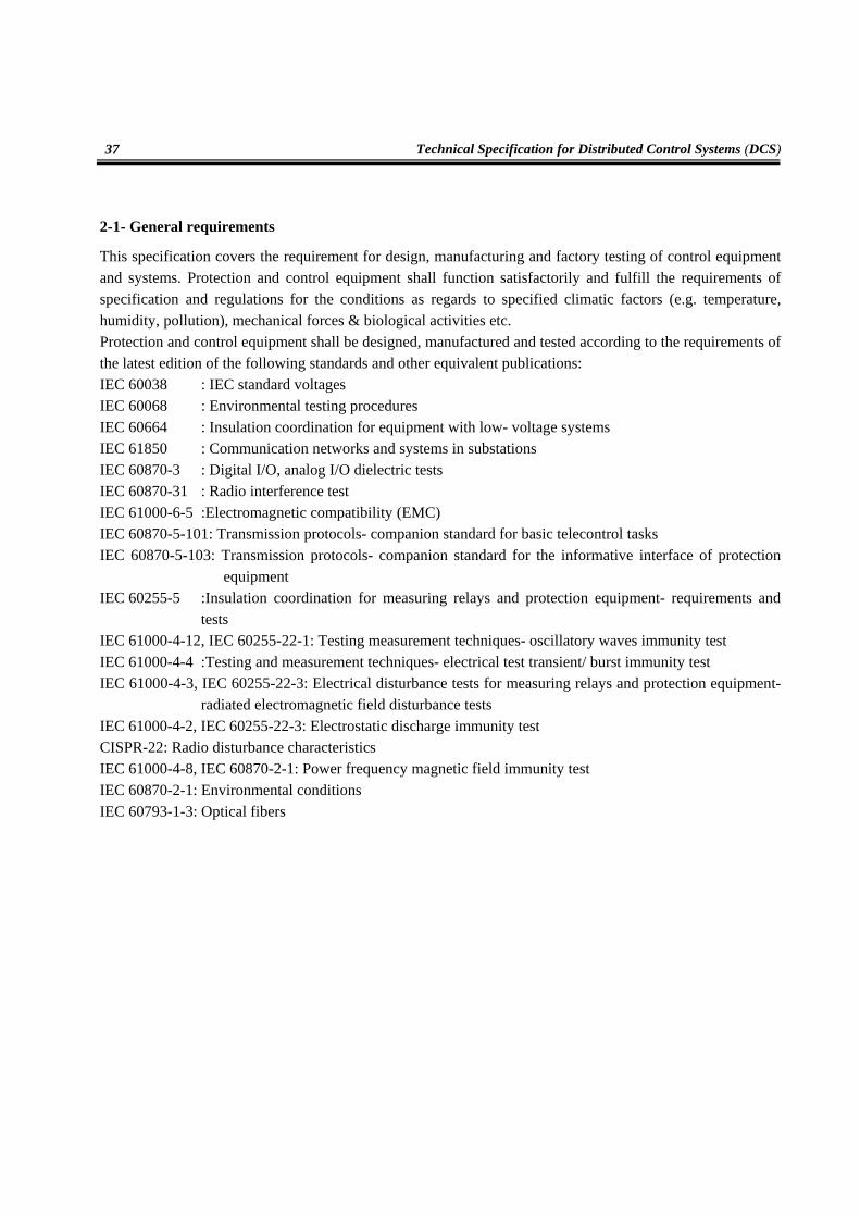
2-1- General requirements
This specification covers the requirement for design, manufacturing and factory testing of control equipment and systems. Protection and control equipment shall function satisfactorily and fulfill the requirements of specification and regulations for the conditions as regards to specified climatic factors (e.g. temperature, humidity, pollution), mechanical forces & biological activities etc. Protection and control equipment shall be designed, manufactured and tested according to the requirements of the latest edition of the following standards and other equivalent publications: IEC 60038 : IEC standard voltages IEC 60068 : Environmental testing procedures IEC 60664 : Insulation coordination for equipment with low- voltage systems IEC 61850 : Communication networks and systems in substations IEC 60870-3 : Digital I/O, analog I/O dielectric tests IEC 60870-31 : Radio interference test IEC 61000-6-5 :Electromagnetic compatibility (EMC) IEC 60870-5-101: Transmission protocols- companion standard for basic telecontrol tasks IEC 60870-5-103: Transmission protocols- companion standard for the informative interface of protection
equipment IEC 60255-5 :Insulation coordination for measuring relays and protection equipment- requirements and
tests IEC 61000-4-12, IEC 60255-22-1: Testing measurement techniques- oscillatory waves immunity test IEC 61000-4-4 :Testing and measurement techniques- electrical test transient/ burst immunity test IEC 61000-4-3, IEC 60255-22-3: Electrical disturbance tests for measuring relays and protection equipment-
radiated electromagnetic field disturbance tests IEC 61000-4-2, IEC 60255-22-3: Electrostatic discharge immunity test CISPR-22: Radio disturbance characteristics IEC 61000-4-8, IEC 60870-2-1: Power frequency magnetic field immunity test IEC 60870-2-1: Environmental conditions IEC 60793-1-3: Optical fibers

Technical Specification for Control and Automation Systems of High Voltage Substations
38
2-2- System architecture
The control system shall perform it's functions without human interposing and automatically. In addition control equipments shall perform their functions with proper accuracy and speed, high reliability security and availability so the accuracy, rate, reliability shall be considered in hardware and software design. The control system shall be flexible for extension of substation. Control system shall be exploited and tested for a specific time period. The design of the system must be such that personnel without any computing background shall be able to operate the system with ease and, incorporated with user- friendly features, without causing undue operational delays. The operator shall have the option to request for help messages to assist him in executing the various functions, should he so desire. The messages issued to the operator to inform him of action to take and explanations of errors in the system shall be precise comprehensible. Coded messages are not acceptable. The system shall provide minimum three levels of passwords to prevent from unauthorized operation of the system. Additionally there shall be one system password providing also the engineering and database editing facilities.
2-2-1- Station level controller
The station level controller shall be responsible for data reprocessing and transfer to one or several control centers, neighboring substations and related maintenance centers. It is installed in the control room of the substation and thus forms, in combination with the human machine interface, the station control level. In addition to these tasks it provides communication to protection relays and it carries out all overlapped automatic feeder functions and interlocks. The station level controller shall be capable to handle multiple serial lines with different protocols and individual database for communication to various control centers, satellite RTUs and intelligent electronic devices. It shall be supplied with compatible communication protocol and interfacing equipment to enable remote communication with SCADA systems at different control centers. The station level controller shall provide data filtering and preprocessing facilities to select, group and modify data for each individual control and maintenance center using standard engineering tools. Different communication protocols at different ports of the station level controller shall be possible at the same time. The station level controller shall be mounted in a panel within the substation control room area specified for control panels. The communication medium to all bay control units and, if applicable, numerical protection relays shall be fiber optical cables via the station bus. Communication to local peripherals may be copper conductor. Provision of communication interfaces shall be made for the future system expansion.

Technical Specification for Distributed Control Systems (DCS)
39
The communication interfaces to multiple higher- level control centers shall be provided. Interfaces and software functions shall enable external systems and control facilities from other manufacturers to communicate with the system. The data transmission protocols and all other functions for communication with external computers and telecommunication system shall be capable of being loaded into the station level controller. The station level controller shall meet the following requirements:
• Programmable logical control (PLC) facilities according to IEC 61131-3 and IEC 61850-6 in order to support the following functions:
- Station wide interlocking - Centralized command sequence control and co-ordination - Station wide automatic procedures such as busbar transfer, automatic transformer switch over
and inter bay logics • Autonomous functionality of each board and module i.e. in case the main CPU board fails the
individual boards shall operate autonomously. • Self- supervision and self- diagnostics. • The station level controller shall ensure remote control, monitoring and supervision of the entire
substation from different control and maintenance centers. • Interface via conventional I/O boards:
- Conventional control panel attached in the control room (if required) - Pulse contact inputs for energy metering - Digital and analogue inputs for station battery alarm, fire alarm, etc.
• Interface via the station LAN with independent and individual database for each connection. - Station human machine interface (HMI) - Local or remote engineering tool - Up to 10 remote control or maintenance centers - External clock source from GPS clock receiver (via NTP) - Bay control units - IEDs such as protection relays directly connected to the station LAN
• Interface via serial communication lines: - Protection relays provided with serial interfaces according to IEC 60870-4-103 (part 1 and 2) - Neighboring substations via protocol IEC 60870-4-101
All hardware cards for station level controller shall comply with the following tests in the final installed state: Isolation: IEC 60255-5 HF disturbance test: IEC 61000-4-12 IEC 60255-22-1

Technical Specification for Control and Automation Systems of High Voltage Substations
40
Transient disturbances: IEC 61000-4-4 Electromagnetic fields: IEC 61000-4-3 IEC 60255-22-3 Static discharge (ESD test): IEC 61000-4-2 IEC 60255-22-3, class 3 Spark disturbance: CISRP 22 Magnetic fields (50 Hz): IEC 61000-4-8 IEC 60870-2-1, class 4 Climatic environmental condition: IEC 60870-2-2:96, class B2
2-2-2- Bay Control Units
The bay control unit shall be an intelligent microprocessor based device capable of both data acquisition and local processing. At bay level, each bay shall have a single dedicated bay control unit just for substation control functions separated from any protection relay functions. The bay control units shall be equipped with a full graphic LCD- display for the display of single- line diagrams, equipment status (open/ close), measurement values and alarms. In the case of communication failure to the station level controller, the bay control units shall operate as independent units and acquire, process and store data in the local buffer and perform local functions without interruption. When the fault is cleared, the bay controller shall transmit all the data that has not yet being transmitted to the station controller. In the event of power supply failure, the bay controller shall retain all parameter settings and functions by mean of non- volatile memory without the use of backup battery. The process I/O facilities contained within the control system shall include analogue inputs, digital inputs, pulse accumulator inputs and command outputs as necessary. All input and output signals from the terminal shall be electrically isolated from the rest of the electronic equipment, by means of optocouplers at the input. LED shall indicate the state of binary I/Os of the bay control unit on the respective I/O board front panel. The system shall be designed such that failure in a part or parts of the system will not affect the operation of the rest of the system. Data integrity must be maintained at all times and there shall be no possibility of loss of data. Hardware faults developing in one part of the system shall be localized and not be allowed to spread or cause other parts to be affected. Events, alarms and commands shall be time- tagged on the I/O board with a resolution of 1ms. The time- tagged events shall be available at the HMI and at the remote control centers for logging and archiving. The following functions shall be incorporated in the Bay Control Units;
• Data acquisition

Technical Specification for Distributed Control Systems (DCS)
41
• Monitoring and control of HV apparatus such as isolators, earthing switches and circuit breaker • Synchrocheck of circuit breakers • Bay interlocking and station wide interlocking form its own data as well as data from other bays via
station bus • Automatic/manual on-load tap changer control for voltage regulation for power transformers • Automatic/manual parallel operation of on-load tap changer control for power transformers • Auxiliary control of power transformers cooling system • Bay level sequential control functions, voltage selection, etc. • Self- supervision and self- diagnostics • Interface to the station level controller and the station HMI • Supervision of unbalanced load such as 3-phase currents and voltages plausibility check • Supervision of analogue input such as three phase voltages • Event time tagging of 1 ms resolution • Measurement and calculation of bay process variables such as 3- phase currents, 3-phase voltages,
active and reactive power, frequency, phase angle and energy counting • Under frequency or voltage load shedding and restoration • Condition based maintenance of the substation • Interface to protection relays
All hardware cards for the bay control units shall comply with the tests mentioned for state controller.
2-2-3- Redundant station level controllers
The station level controller shall be redundant. Identical application programs shall be running in the redundant station level controllers. Data in monitoring direction (data from the BCU, protection relays,…) shall be always sent to both station level controllers. Data in control direction (commands, setpoints) shall be routed only via the active station level controller. A switchover from passive to active station control device shall be performed without interruption. Immediately after the switch over from passive to active it shall be guaranteed that a general interrogation (GA) is performed, which automatically shall update the system with the current state of data. The switch over after error recognition shall be up to 1s. 2-3- Mechanical considerations Control outdoor equipments shall protect with suitable guards according to standards ANSI/NEMA ICS6. Control indoor equipments shall protect with guards according to standard ANSIC83.9.

Technical Specification for Control and Automation Systems of High Voltage Substations
42
2-4- Inspection and tests
The tests are intended to demonstrate that the individual hardware units and items of software are operational and comply with their individual specification, that they are compatible under these conditions and that when assembled into a complete system, they will operate together with the associated operational and test programs over an extended period with an acceptably low outage time in the environmental condition specified. The equipment offered shall be subjected to the following tests:
• Type tests: These are intended to be fully comprehensive tests for proving that the design of the equipment complies with this specification.
• Routine tests: These are tests normally applied to equipment during manufacturing. • Functional and performance tests: These are tests conducted to ensure that the equipment meets all
the functional requirements of the specification under the most adverse operational conditions that can be encountered at the sites.
2-4-1- Type tests
Hardware The type test certificates of all cards of the substation automation system shall be submitted as proof that the cards have being type-tested. It is mandatory for the bidder to submit all the relevant type test reports. The control system shall certified by a reputable office. Software Individual program tests will normally only be carried out by the contractor. Such cases shall be determined by mutual agreement between the client and the contractor. The correct performance of the system with various relays shall approved by a reputable office.
2-4-2- Routine tests
The routine tests shall include, but shall not be limited to the following: • Wiring: All apparatus on each panel, cubicle or rack shall be tested to a voltage equal to the test
voltage specified for the apparatus connected to it. • Instruments: Instruments shall be tested in accordance with its relevant specification. • Isolation equipment: Isolation equipment shall be tested at their specified withstand voltage,
between the line terminals and the apparatus terminals and between the line terminals and the framework and covers.
2-4-3- Functional and performance tests The tests are intended to check the following:
• Visual test: A visual inspection of the complete system shall be carried out to ensure conformity with the specification with regard to quality and workmanship.
• That the units operate correctly when connected as a system in its operational configuration in accordance with the specification.

Technical Specification for Distributed Control Systems (DCS)
43
• For comparability of the parts under the environmental conditions and power supply variations. • That all displays and logs present the correct information. • The software and hardware errors and design weaknesses are brought to light and corrected before
the system leaves the works. • That the fault rate of both the hardware and software is acceptably low during the extended period of
operation (i.e. soak test) and that the availability of the complete system is high.
2-4-4- Factory Acceptance Tests (FAT)
The contractor shall provide documented evidence that the system meets the specification before the client deems that the system is ready for the FAT. The complete system shall be made available and connected together for the tests. Testing of the system in parts will not be allowed. For the purpose of evaluating the system performance, the scenario under steady state and high activity conditions will be simulated using hardware and software tools to be provided by the contractor. The formal FAT will be witnessed and conducted in some parts by client's personnel and shall include, but not necessarily be limited to the following:
• All system components including local control panels shall be exercised in all operational modes • All functional interfaces shall be verified • All human- machine interface functions shall be demonstrated • All input/ output points shall be individually verified for correctness • All software functions shall be demonstrated to be operational • All alarm and error detection functions shall be checked • All diagnostic routines shall be checked • All software maintenance procedures shall be checked • Test of the systems ability to handle improper operation • One relay from each type of protective relays shall be tested in accordance with control system and
it's performance Major items of equipment shall not be shipped until the FAT of the whole system has been satisfactorily concluded and approved for shipment by the client. 2-4-5- Site tests The contractor shall be responsible for the submission of all plant for site tests and inspection as required by the client. During the course of erection, the client shall have full access for inspection of the progress of work and for checking workmanship and accuracy as may be required. On completion of the work prior to commissioning, all equipment shall be tested to the satisfaction of the client to demonstrate that it is entirely suitable for commercial operation. Qualified technical representatives of the contractor shall carry out commissioning tests in the presence, of the client. The tests shall be exhaustive and shall demonstrate that the overall performance of the contract works satisfies every requirement specified.

Technical Specification for Control and Automation Systems of High Voltage Substations
44
2-5- Training
It is the intention of the client to undertake the maintenance of the whole installation after the warranty period. As such, the contractor shall instruct the client's personnel, both at place of manufacturer's works and at site, in the operation and maintenance (including trouble- shooting and repair) of all equipment supplied under this contract. The contractor shall satisfy himself and the client that the client's employees are fully capable of operating and maintaining the system before the contractor's personnel leave the site. Tenderers are required to submit the following recommendations:
• Full details of training facilities as well the type of courses available. • Details and duration of the formal hardware and software training program and courses. • Proposed location for the formal hardware and software training courses and training.
The formal training courses for hardware and software shall be scheduled to be conducted consecutively, so that each trainee can attend both the hardware and the software courses. The maintenance procedures taught shall be fully documented in the maintenance manuals of the individual equipment and of the appropriate system. The cost of all materials (including documents) shall be included in the contract price. The contractor shall provide the trainees with all the course material text, at the latest one month before they are due to start their training. The contractor shall train the client's engineers in the maintenance of all items of hardware (including peripherals, controllers, communication, integrated RTU, etc.). The formal training shall include classroom sessions covering the theory and design of the system, execution of diagnostic programs, hands-on exercise on fault tracing and routine maintenance, and the use of any special tools or test equipment for the system. The contractor shall also undertake to train the client's engineers on all aspects of software maintenance including but not necessarily be limited to, the following:
• The operating system • All application software packages • Program modification and integration • Database files structure and expansion of files • Database data specification and modification process • VDU display specification and modifications • Integration of additional peripherals
The contractor shall also carry on reconfiguration courses at suitable time and with schedule approved by client.
2-6- Online Diagnosis and maintenance
The substation control system shall allow that all other components remain in operation and are not affected when changing, replacing and updating of one component and these changes shall only concern the respective component. Changing of peripheral elements (I/O boards) shall be possible via "hot plug and play" – i.e. without restart of the respective component. If the firmware of a processing board (CPU) shall be reloaded, the system shall support online (during operation of the unit) loading and this is followed by a reset of the board only.
Technical Specification for Distributed Control Systems (DCS)
45
The time of non availability of the component shall be limited to 3 minutes, while the remaining system shall be in operation during this time. Diagnosis shall be possible during the normal operation and without reducing the performance of the system. If parameters need to be changed for any purposes, a reset of the respective component- not a reset of the whole system- is allowed. During the reset, the component is not available, but the rest of the automation system shall remain in full operation.
2-7- Documentation
All the documentation shall be written in English language in a clear and accurate manner, as a minimum, the set of documentation to be supplied with the system shall comprise the following: • Hardware maintained manual for each item of equipment, this shall include:
- Overall block and interconnecting diagrams - Detail circuit diagram for each unit, sub-unit, and plug- in board integrated circuit used in the system. - Service diagram for maintenance purposes. - Logic diagrams - Equipment information drawings. - Cubicle wiring diagram - Theory of operation of the system - Detail description of the function of each unit and sub-unit, its mode operation and the relationship
between the units and sub-units. - Maintenance instructions. - Hardware trouble shooting guide - Detailed description of hardware diagnostic program
• Operation manual for each item of equipment • Software maintenance manual for all the programs and data • Software maintenance guides for all the software • Operator's manual for control and HMI functions • Maintenance record of the system supplied.
2-8- Functional allocating
Indications, measurement and control functions shall assigned to different control level as below (table 1 to 4)

Technical Specification for Control and Automation Systems of High Voltage Substations
46
Table 1: Assigning of indication functions
Assigning of function Bay level control Station level control
Function Bay Control Unit
Local Control
Remote Control Archiving Control
Function
Remove of invalid info * Remove of transient info *
Management of intermediate info * Provide of detail info * *
CB status * Audible alarms * *
Remove of dependent info * * Database management * * * *
Process supervision * * * *
Table 2: Assigning of measurement functions to different control level
Assigning of function Bay level control Station level control
Function Bay Control Unit
Local Control
Remote Control Archiving Control
Function Active, reactive power calculation *
Limit value monitoring * * Unbalancy monitoring from limits * * Accumulation of measured values * * * Determination of min/max value *
Value replacement * * * *

Technical Specification for Distributed Control Systems (DCS)
47
Table 3: Assigning of control functions to different control levels
Assigning of function Bay level control Station level control
Function Bay Control Unit
Local Control
Remote Control Archiving Control
Function Unit control *
Transformer tap changer * Command delay monitoring *
Switching sequences * * Automatic acknowledgement *
Synchrocheck * Bay interlocking *
Station interlocking * * Immunity test *
Capacitor bank control *
Table 4: Assigning of system functions
Assigning of function Bay level control Station level control
Function Bay Control Unit
Local Control
Remote Control Archiving Control
Function Time synchronization * * * * System configuration * * * System information *
Self supervision * * * * * Integration of measured value *
Archiving * * Listing of data *
Database management * Fault recording *
2-9- Optical fiber
In substation automation systems, the communication media shall be optical fiber. The core and cover of fiber shall be glass type. The cover shall be a material with good tenacity, for more protection of fiber the buffer shall be used as a layer on cover. The color of buffer may vary but this color shall be compatible with IEC standard (IEC 60304). Optical fibers shall be tested before delivery. This test issued according to IEC 60793-1-3 standard. The fiber shall be endurable up to 0.5 percent of length increase. The bandwidth and wavelength requirements shall be considered when the optical fibers is used for communication.

Technical Specification for Control and Automation Systems of High Voltage Substations
48
The reflex of optical fibers shall be considered according to rotation limits in all routes and cable ducts so the routes and ducts of fibers shall be separate form other cable types and installed above the other routes. The spare parts and adequate spare length of fiber shall be considered for installation and splicing (such as cassette, flexible fiber …)

Technical Specification for Distributed Control Systems (DCS)
49
SCHEDULE (I) RATING AND CHARACTERISTICS OF DISTRIBUTED CONTROL SYSTEM
ITEM DESCRIPTION TECHNICAL PARTICULARS 1 System functional requirements
1-1 Capability of levels of system access protection Yes/No Yes 1-2 Multiple passwords available within each level of
system access Yes/No Yes 1-3 Single line display Yes/No Yes 1-4 Event processing facility Yes/No Yes 1-5 Alarm processing facility Yes/No Yes 1-6 Analogue measurement handling (e.g. "change of
state or other methods" Yes/No Yes 1-7 Scheduled logging facility Yes/No Yes 1-8 Page logging facility to hard copy colour printer Yes/No Yes 1-9 Sequence display Yes/No Yes
1-10 Plant database schedule Yes/No Yes 1-11 Operator manual entry facility Yes/No Yes 1-12 Equipment status display Yes/No Yes 1-13 Fault incident record facility Yes/No Yes 1-14 Tap position by binary or digital input Both is possible 1-15 Provision of simple method of database and
display updating, also system manager tasks. Details of proposals included? Yes/No Yes
1-16 Tagging facility Yes/No Yes 1-17 Interlocking /redundancy feature Yes/No Optional 1-18 Synschro-check Yes/No Yes 1-19 Automatic and manual tap changer control Yes/No Yes
2 Hardware and software 2-1 Computer equipping for ultimate system Yes/No Yes 2-2 Editing tools for sequential/logic functions Yes/No Yes 2-3 Analogue accuracy form bay unit to display <0.5% 2-4 Automatic/manual diagnostics provided for all
SCS & SMS equipment Yes/No Yes 2-5 Automatic system restart following power
interruption Yes/No Yes 2-6 Fault/event recorder files auto upload to SCMS Yes/No Yes 2-7 Redundant station computer configuration Yes/No Optional

Technical Specification for Control and Automation Systems of High Voltage Substations
50
SCHEDULE (I) RATING AND CHARACTERISTICS OF DISTRIBUTED CONTROL SYSTEM
ITEM DESCRIPTION TECHNICAL PARTICULARS 3 Station computer
3-1 Type industrial 3-2 Architecture * 3-3 Hard disc storage * 4 Peripheral server
4-1 Type Acc .to topology 4-2 AC voltage working range volts Acc .to topology 4-3 Service conditions Acc .to topology 4-4 Power consumption Acc .to topology 4-5 Number of LAN connections 2 4-6 Number of peripheral ports Acc .to requirement 4-7 Protocols supported TCP/IP 5 Operator workstation
5-1 Type Industrial 5-2 Architecture Acc .to requirement 5-3 Operating system software * 5-4 Method of processor expansion * 5-5 Supplied size main memory * 5-6 Hard disc storage * 5-7 Clock *
5-7-1 Drift per day (when not synchronized master clock) 3 sec/day 5-7-2 Method of synchronization with master clock by servers 5-8 Processing system intercommunications interface LAN
5-8-1 Number supported * 5-8-2 Speed * 5-9 VDU *
5-9-1 Number to be supplied at a workstation * 5-9-2 Complacence with recognized EMC and safety standards Yes

Technical Specification for Distributed Control Systems (DCS)
51
SCHEDULE (I) RATING AND CHARACTERISTICS OF DISTRIBUTED CONTROL SYSTEM
ITEM DESCRIPTION TECHNICAL PARTICULARS 6 Laptop workstation and SCS & SMS dial in fault
analysis facility
6-1 Service conditions * 6-2 Method of processor expansion * 6-3 Amount of main memory * 6-4 Size of hard disc * 6-5 Processor speed * 6-6 Operating system software * 6-7 SCS & SMS application software * 6-8 Relay and fault recorder analysis software * 6-9 Details of SCS gateway * 7 Event printer Yes/No Yes 8 Hard copy colour laser printer * 9 Master clock
9-1 type * 9-2 Drift per day * 9-3 Local alarms and contacts for alarms to SCS & SMS. Yes/No Yes 10 Furniture
10-1 Workstation desk Yes/No * 11 Workstation LAN
11-1 Type LAN 11-2 Coaxial/ optical fiber cable * 11-3 Operating speed HZ * 11-4 Protocols TCP/IP 11-5 Network management software * 11-6 Dual redundant configuration Optional 12 Real time LAN
12-1 Type Ethernet

Technical Specification for Control and Automation Systems of High Voltage Substations
52
SCHEDULE (I) RATING AND CHARACTERISTICS OF DISTRIBUTED CONTROL SYSTEM
ITEM DESCRIPTION TECHNICAL PARTICULARS 12-2 Coaxial optical fiber cable Fiber optic 12-3 Operating speed HZ * 12-4 Dual redundant configuration Yes/No optional 13 Communications
13-1 Protocol between station commuter and BCU/BCPU * 13-1-1 Info. transfer efficiency (data bits/total bits) No loss of data 13-1-2 Security of control messages Yes/No Yes 13-1-3 Interface Fiber optic 13-1-4 Transmission rate * 13-2 Type and No. of communication cables to
BCU/BCPU
* 13-3 Type & No. of communication cables to protection
relay and disturbance recorder
* 13-4 Laptop workstation and SCS & SMS fault analysis * 13-5 Communications with adjacent SCS & SMS system *
13-5-1 protocol * 13-5-2 Transmission rate *
14 BCU 14-1 DC voltage working range volts * 14-2 service conditions * 14-3 Architecture * 14-4 System bus interface/speed * 14-5 Provision of two redundant interfaces to LAN Yes/No Optional 14-6 Logic functions & sequences Yes/No Yes 14-7 Clock Yes/No Yes 14-8 Digital inputs
14-8-1 Number of inputs per module * 14-8-2 Digital/software filtering to suppress plant contact
bounce Yes/ No Yes 14-8-3 Time tagging resolution * 14-9 Digital outputs
14-9-1 Number of inputs per module * 14-9-2 Select/check back/ execute facility Yes/No Yes

Technical Specification for Distributed Control Systems (DCS)
53
SCHEDULE (I) RATING AND CHARACTERISTICS OF DISTRIBUTED CONTROL SYSTEM
ITEM DESCRIPTION TECHNICAL PARTICULARS 15 System software
15-1 Make and version of operating system(s) * 15-2 Details of programming language(s) * 15-3 Release versions of software Latest version 16 Performance/availability
16-1 Compliance with performance requirements (start and restart) Yes/No Yes
16-2 Time for redundant station computer to assume online duties
*
16-3 Time for full updating of information * 16-4 Inclusion of availability calculations * 17 Inverter
17-1 Type online 17-2 Input dc voltage and range volts * 17-3 Output Ac voltage range. volts * 17-4 Output rating watts * 18 Static switch
18-1 Type Static 18-2 Input dc voltage and range volts * 18-3 Input frequency range Hz * 18-4 Services conditions (temperature and RH) * 18-5 Rating Amps * 19 Power supply housing
19-1 Forced cooling/alarming Yes/No Yes 20 BCR
20-1 Dimension * 20-2 Number of BCRS Acc. to requirement 21 Fiber optics
21-1 Type * 21-2 Class *
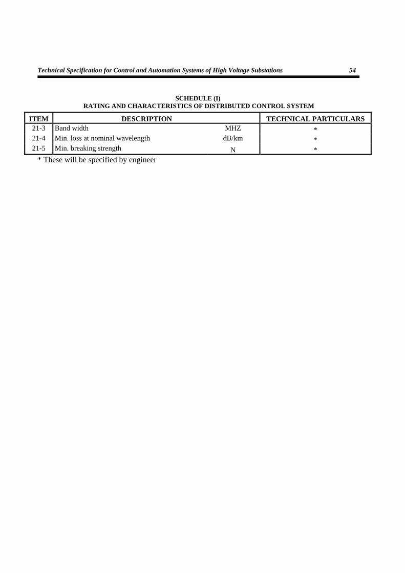
Technical Specification for Control and Automation Systems of High Voltage Substations
54
SCHEDULE (I) RATING AND CHARACTERISTICS OF DISTRIBUTED CONTROL SYSTEM
ITEM DESCRIPTION TECHNICAL PARTICULARS 21-3 Band width MHZ * 21-4 Min. loss at nominal wavelength dB/km * 21-5 Min. breaking strength N *
* These will be specified by engineer

Technical Specification for Distributed Control Systems (DCS)
55
SCHEDULE (II) GUARANTEED THCHNICAL INFORMATION OF DISTRIBUTED CONTROL SYSTEMS
(TO BE SUPPLIED WITH TENDER)
ITEM DESCRIPTION TECHNICAL PARTICULARS 1 System functional requirements
1-1 No. of levels of system access protection 1-2 Multiple passwords available within each level of system
access? Yes/No 1-3 System functioning does not require multiple alarm
acknowledgement of manual entries? Yes/No 1-4 Substation by single line displays with paging? Yes/No 1-5 Multiple windows with size selectable? Yes/No 1-6 Event processing facility? Yes/No 1-7 Alarm processing facility? Yes/No 1-8 Separate loud ringing audible alarm? Yes/No 1-9 Analogue measurement handling? Yes/No 1-10 MWH & MVARH data from plant or calculated 1-11 Individual and sequence control facilities? Yes/No 1-12 Scheduled logging facility? Yes/No 1-13 Method of storage of historical data 1-14 Plant database schedule? Yes/No 1-15 Operator manual entry facility? Yes/No 1-16 SCMS equipment status display? Yes/No 1-17 Fault incident record facility? Yes/No 1-18 Tap position by binary or digital input? Yes/No 1-19 Provision of simple method of database and display
updating also system manager tasks. Details of proposals included? Yes/No
1-20 Tagging facility? Yes/No 1-21 Interlocking/ redundancy feature? Yes/No 1-22 Synchro- check? Yes/No 1-23 Automatic and manual tap change control? Yes/No
2 SCMS hardware and software 2-1 Computer equipping for ultimate system Yes/No 2-2 Integrated SCS & SMS database/more than one database

Technical Specification for Control and Automation Systems of High Voltage Substations
56
SCHEDULE (II) GUARANTEED THCHNICAL INFORMATION OF DISTRIBUTED CONTROL SYSTEMS
(TO BE SUPPLIED WITH TENDER)
ITEM DESCRIPTION TECHNICAL PARTICULARS 2-3 Compatibility of database tools with tools at SCADA
control center? Yes/No 2-4 Editing tools for sequential/ logic functions? Yes/No 2-5 Analogue accuracy from bay unit to display 2-6 Automatic /manual diagnostics provided for all SCS
& SMS equipment? Yes/No 2-7 Automatic system restart following power interruption Yes/No 2-8 Stall alarm facility? Yes/No 2-9 Fault/event recorder files auto upload to SCMS? Yes/No
2-10 Redundant station computer configuration Yes/No 3 Station computer
3-1 Manufacturer/ model 3-2 Type 3-3 AC voltage working range volts 3-4 Service conditions 3-5 Power consumption watts 3-6 Architecture 3-7 Individual processors for each function 3-8 Operating system software 3-9 Method of processor expansion
3-10 Main (semiconductor) memory 3-10-1 Type 3-10-2 Supplied size 3-10-3 Maximum size 3-11 Hard disc storage
3-11-1 Type 3-11-2 Supplied size 3-11-3 Maximum size 3-12 Clock
3-12-1 Type 3-12-2 Drift per day (when not synchronized to master clock) 3-12-3 Method of synchronization with master clock 3-12-4 Battery backup

Technical Specification for Distributed Control Systems (DCS)
57
SCHEDULE (II) GUARANTEED THCHNICAL INFORMATION OF DISTRIBUTED CONTROL SYSTEMS
(TO BE SUPPLIED WITH TENDER)
ITEM DESCRIPTION TECHNICAL PARTICULARS 3-13 Details of mass storage devices and data archiving
devices 4 Peripheral server
4-1 Manufacturer /model 4-2 Type 4-3 AC voltage working range volts 4-4 Service conditions 4-5 Power consumption watts 4-6 Number of LAN connections 4-7 Number of peripheral ports 4-8 Number of communications speeds 4-9 Protocols supported 5 Operator workstation
5-1 Manufacturer/ model 5-2 Type 5-3 AC voltage working range volts 5-4 Service conditions 5-5 Power consumption watts 5-6 Architecture 5-7 Operating system software 5-8 Method of processor expansion 5-9 Main (semiconductor) memory
5-9-1 Type 5-9-2 Supplied size 5-9-3 Maximum size 5-9-4 Battery back up system 5-10 Hard disc storage 5-11 Clock
5-11-1 Type 5-11-2 Drift per day (when not synchronized with master clock) 5-11-3 Method of synchronization with master clock)
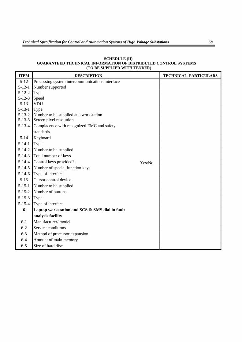
Technical Specification for Control and Automation Systems of High Voltage Substations
58
SCHEDULE (II) GUARANTEED THCHNICAL INFORMATION OF DISTRIBUTED CONTROL SYSTEMS
(TO BE SUPPLIED WITH TENDER)
ITEM DESCRIPTION TECHNICAL PARTICULARS 5-12 Processing system intercommunications interface
5-12-1 Number supported 5-12-2 Type 5-12-3 Speed 5-13 VDU
5-13-1 Type 5-13-2 Number to be supplied at a workstation 5-13-3 Screen pixel resolution 5-13-4 Complacence with recognized EMC and safety
standards 5-14 Keyboard
5-14-1 Type 5-14-2 Number to be supplied 5-14-3 Total number of keys 5-14-4 Control keys provided? Yes/No 5-14-5 Number of special function keys 5-14-6 Type of interface 5-15 Cursor control device
5-15-1 Number to be supplied 5-15-2 Number of buttons 5-15-3 Type 5-15-4 Type of interface
6 Laptop workstation and SCS & SMS dial in fault analysis facility
6-1 Manufacturer/ model 6-2 Service conditions 6-3 Method of processor expansion 6-4 Amount of main memory 6-5 Size of hard disc

Technical Specification for Distributed Control Systems (DCS)
59
SCHEDULE (II) GUARANTEED THCHNICAL INFORMATION OF DISTRIBUTED CONTROL SYSTEMS
(TO BE SUPPLIED WITH TENDER)
ITEM DESCRIPTION TECHNICAL PARTICULARS 6-6 Processor speed 6-7 Operating system software 6-8 SCS & SMS application software 6-9 Relay and fault recorder analysis software
6-10 Mains power supply unit 6-11 Battery back up period 6-12 Modem/speed/ connecting lead 6-13 Details of SCS& SMS gateway 6-14 Details of manufacturers dial in SCS & SMS fault
analysis facilities 7 Event printer
7-1 Manufacturer/ model 7-2 Type 7-3 AC voltage working range volts 7-4 Power consumption watts 7-5 Service conditions 7-6 Print speed ppm 7-7 No. of print pins/ jets or resolution 7-8 Paper feed proposed/ width 7-9 Number of colours
7-10 Type of interface 7-11 Acoustic noise at one meter dB 7-12 Alarm local and remote 7-13 Configuration/dual network connection
8 Hard copy colour laser printer 8-1 Manufacturer/ model 8-2 Type 8-3 AC voltage working range volts 8-4 Power consumption watts 8-5 Service condition 8-6 Print speed for colour graphics printing ppm

Technical Specification for Control and Automation Systems of High Voltage Substations
60
SCHEDULE (II) GUARANTEED THCHNICAL INFORMATION OF DISTRIBUTED CONTROL SYSTEMS
(TO BE SUPPLIED WITH TENDER)
ITEM DESCRIPTION TECHNICAL PARTICULARS8-7 Resolution 8-8 Type of interface 8-9 Acoustic noise at one meter dB
8-10 Alarms local and remote 8-11 Configuration/dual network connection
9 Master clock 9-1 Manufacturer/ model 9-2 Type 93 AC/DC voltage working range volts 9-4 Power consumption watts 9-5 Service condition 9-6 Battery standby capacity Ah 9-7 Type, speed and no. of output interfaces 9-8 Time and data facility 9-9 Local display
9-9-1 Day: Mon: Yr 9-9-2 HH: MM: SS 9-10 Drift per day (when not synchronized to radio
signal) 9-11 Receiver for up from NAVSTAR satellites 9-12 Other alarms 9-13 Local alarms and contacts for alarms to SCS &
SMS Yes/No 10 Furniture
10-1 Workstation desk 10-1-1 Material of desk 10-1-2 Support for VDUs 10-1-3 Size 10-1-4 Height 10-2 Workstation chair

Technical Specification for Distributed Control Systems (DCS)
61
SCHEDULE (II) GUARANTEED THCHNICAL INFORMATION OF DISTRIBUTED CONTROL SYSTEMS
(TO BE SUPPLIED WITH TENDER)
ITEM DESCRIPTION TECHNICAL PARTICULARS11 Workstation LAN
11-1 Manufacturer/model 11-2 Type 11-3 Coaxial/optical fiber cable 11-4 Operating speed HZ 11-5 Protocols/compliance with OSI 7498 11-6 Media connection 11-7 Network management software 11-8 Software packages 11-9 Dual redundant configuration? Yes/No 12 Real time LAN
12-1 Manufacturer/model 12-2 Type 12-3 Coaxial/optical fiber cable 12-4 Operating speed HZ 12-5 Protocols/ compliance with OSI 7498 12-6 Network functionality 12-7 Network management 12-8 Software packages 12-9 Dual redundant configuration? Yes/No
12-10 Deterministic operational behavior Yes/No 13 Communications
13-1 Protocol between station computer and BCU/BCPU 13-1-1 Manufacturer/model 13-1-2 Compliant with IEC 61850 Yes/No 13-1-3 Info. Transfer efficiency (data bits/ total bits) 13-1-4 Security of control messages Yes/No 13-1-5 Interface 13-1-6 Transmission rate 13-2 Type and no. of communication cables to BCU/BCPU 13-3 Type & no. of communication cables to protection
relay and disturbance recorder

Technical Specification for Control and Automation Systems of High Voltage Substations
62
SCHEDULE (II) GUARANTEED THCHNICAL IN FORMATION OF DISTRIBUTED CONTROL SYSTEMS
(TO BE SUPPLIED WITH TENDER)
ITEM DESCRIPTION TECHNICAL PARTICULARS13-4 LDC modem:
13-4-1 Manufacturer and model 13-4-2 Type 13-4-3 DC voltage working range volts 13-4-4 Service condition 13-4-5 Signaling method 13-4-6 Transmission output 13-5 Laptop workstation and SCS & SMS fault analysis:
13-5-1 Modem manufacturer and model 13-5-2 Type 13-5-3 Dc voltage working rang volts 13-5-4 Service conditions 13-5-5 Signaling method 13-5-6 Transmission rate and frequency Hz/Mbps 13-5-7 Range of transmitter output 13-5-8 Range of receiver input 13-6 Communications with adjacent SCS & SMS system:
13-6-1 Details of gateway 13-6-2 Provision of optical fiber link 13-6-3 protocol 13-6-4 Transmission rate
14 BCU 14-1 Manufacturer/model 14-2 Type 14-3 DC voltage working range volts 14-4 Service condition 14-5 Power consumption watts 14-6 Architecture 14-7 Memory type 14-8 Memory maximum

Technical Specification for Distributed Control Systems (DCS)
63
SCHEDULE (II) GUARANTEED THCHNICAL INFORMATION OF DISTRIBUTED CONTROL SYSTEMS
(TO BE SUPPLIED WITH TENDER)
ITEM DESCRIPTION TECHNICAL PARTICULARS14-9 System bus interface/speed 14-10 Provision of two redundant interfaces to LAN 14-11 Method of loading /extending database 14-12 Logic functions & sequences Yes/No 14-13 Clock:
14-13-1 Type 14-13-2 Drift per day (when not synchronized to master
clock) 14-13-3 Method of synchronization to master clock 14-13-4 Maximum no. inputs per card 14-13-5 ADC resolution /accuracy 14-13-6 Current input values supported 14-13-7 Scan cycle per ADC 14-13-8 Input isolation (common/series mode) 14-13-9 Series and common mode noise rejection Yes/No
14-13-10 Analogue limit monitoring facility at BCU Yes/No 14-13-11 No. of limits per analogue
14-14 Digital inputs: 14-14-1 Number of inputs per module 14-14-2 Digital/ software filtering to suppress plant contact
bounce Yes/No 14-14-3 Time tagging resolution 14-14-4 Isolation withstand 14-15 Pulse counter signal inputs:
14-15-1 Digital/ software filtering to suppress plant bounce Yes/No 14-15-2 Time tagging resolution 14-15-3 Isolation withstand 14-16 Digital outputs:
14-16-1 Number of inputs per module 14-16-2 Select/check back /execute facility Yes/No 14-16-3 Output rating

Technical Specification for Control and Automation Systems of High Voltage Substations
64
SCHEDULE (II) GUARANTEED THCHNICAL INFORMATION OF DISTRIBUTED CONTROL SYSTEMS
(TO BE SUPPLIED WITH TENDER)
ITEM DESCRIPTION TECHNICAL PARTICULARS14-16-4 Range of output pulse
15 System software 15-1 Make and version of operating system(s) 15-2 Details of programming language (s) 15-3 Release versions of software 16 Performance/availability
16-1 Compliance with performance requirements (start and restart) Yes/No
16-2 Time for redundant station computer to assume online duties
16-3 Time for full updating of information 16-4 Confirmation the redundant station computer
database is in step with the online computer 17 Inverter
17-1 Manufacturer/ model 17-2 Type 17-3 Input dc voltage and range volts 17-4 Service conditions (temperature and RH) 17-5 Output ac voltage range volts 17-6 Output ac voltage and static regulation 17-7 Output frequency regulation (unsynchronized) 17-8 Output ac voltage harmonic distortion 17-9 Output rating watts
17-10 Output current overload Amps 17-11 Output frequency tracking range 17-12 Thermal trip Amps 17-13 Output load power factor 17-14 Efficiency at 25,50 and 100% output
18 Static switch 18-1 Manufacturer/ model 18-2 Type 18-3 Input dc voltage and range volts

Technical Specification for Distributed Control Systems (DCS)
65
SCHEDULE (II) GUARANTEED THCHNICAL INFORMATION OF DISTRIBUTED CONTROL SYSTEMS
(TO BE SUPPLIED WITH TENDER)
ITEM DESCRIPTION TECHNICAL PARTICULARS18-4 Input frequency range Hz 18-5 Service conditions 18-6 Rating Amps 19 Mains bypass (transformer)
19-1 Manufacturer/model 19-2 Type 19-3 Input dc voltage and range. volts 19-4 Input frequency range Hz 19-5 Output voltage regulation 19-6 Service conditions 19-7 Rating Amps 19-8 Output current overload Amps 19-9 Thermal trip Amps 20 Power supply housing
20-1 No. of cubicles 20-2 Forced cooling/ alarming Yes/No 20-3 Noise limits at one meter 20-4 Efficiency & power factor at 25%, 50% and 100% outputs 50-5 Radio frequency interference (production) 21 BCR
21-1 Type/ construction 21-2 Dimension 21-3 No. of BCR's 21-4 Cooling/alarming 21-5 Steel sheet thickness 22 Fiber optics
22-1 Type 22-2 Class

Technical Specification for Control and Automation Systems of High Voltage Substations
66
SCHEDULE (II) GUARANTEED THCHNICAL INFORMATION OF DISTRIBUTED CONTROL SYSTEMS
(TO BE SUPPLIED WITH TENDER)
ITEM DESCRIPTION TECHNICAL PARTICULARS22-3 No. of optical fibers 22-4 Nominal wavelength nm 22-5 Bandwidth MHZ 22-6 Min. loss at nominal wavelength dB/km 22-7 Min. breaking strength N 22-8 Weight kg/km 22-9 Type of fiber
22-10 Manufacturer /country 22-11 Year of production