Embed Size (px)
Citation preview

General Terms and Conditions
Page 1
MINIMUM ORDER CHARGE PER ITEM $200.00
PRICESAll prices are subject to change without notice and orders will be billed at prices in effect at the time of shipment.
TRANSPORTATION TERMSF.O.B. shipping point - Collect. (If premium transportation is requested, the purchaser must bear the burden of expense).
TAXESCMC® prices do not include any taxes, import, or export duties, tariffs, or customs charges. CMC® reserves the right to add to the sales price any applicable sales tax, tariff, duties or customs charges imposed by law on the sale of our products.
PAYMENT TERMSNet 30 days. No cash discounts.
CLAIMS AND ERRORSClaims for shortages, erroneous charges, or price corrections must be presented within 30 days of date of invoice or they will not be allowed. Carriers are responsible for goods lost or damaged in transit.
CANCELLATIONSOrders placed cannot be cancelled or deliveries extended, without the written consent of CMC®, and upon terms, which will indemnify CMC® against all losses. On orders for special items, CMC® reserves the right to invoice cancellation charges for material used and work performed.
RETURNED GOODSAll CMC® connectors are subject to rigid inspection before shipment. Imperfect material, which might occasionally occur in a product run, will be replaced. However, before authorization for return is given, samples of the material must be submitted to CMC for evaluation. Written authorization must be received from CMC® before any material can be returned.
PRODUCT RESPONSIBILITYAs it is impossible to detect all imperfections and control field applications, CMC® guarantees to replace only such goods as proven to be defective. Under no circumstances will CMC® be responsible for any damages beyond the price of the goods. CMC® shall not be liable for losses arising from strikes, fires, floods, riots, acts of God, government action, or procurement.
GOVERNING LAWThis contract shall be governed by and construed in accordance with the laws of the State of Ohio.CMC® products are manufactured under the best quality control standards utilized by our industry.Generally, products are subjected to tests recognized by the National Electrical ManufacturersAssociation (NEMA), American National Standards Institute (ANSI), Underwriters Laboratories (U/L), Canadian Standards Association (CSA), and/or other governing bodies as applicable under the specific circumstances.
Page 2
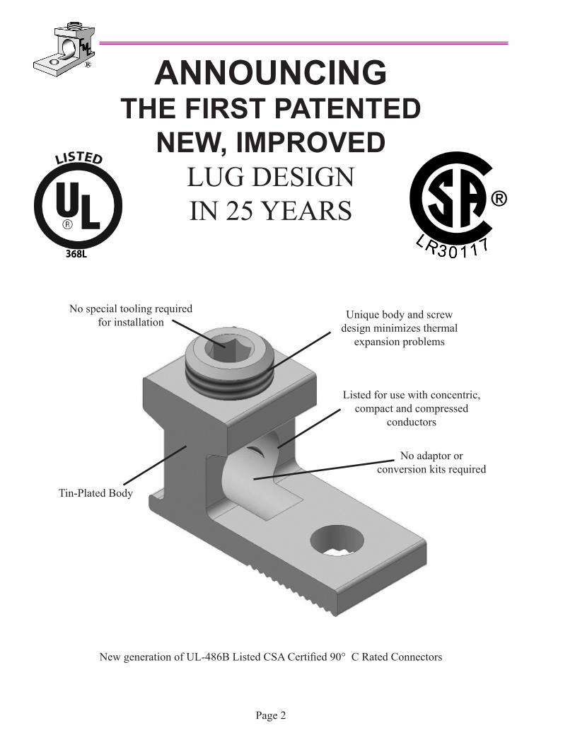
ANNOUNCING THE FIRST PATENTED
NEW, IMPROVEDLUG DESIGN IN 25 YEARS
New generation of UL-486B Listed CSA Certified 90° C Rated Connectors
Unique body and screw design minimizes thermal
expansion problems
Listed for use with concentric, compact and compressed
conductors
Tin-Plated Body
No special tooling required for installation
No adaptor or conversion kits required
Aluminum Dual Rated Mechanical ConnectorsA new generation in mechanical connector performance.
Cool running over 500 heat cycles. Versatile, simple to use and low cost.
IntroductionCMC® introduces PosiGrip® aluminum dual-rated mechanical connectors. The PosiGrip line is designed to meet the rigorous requirements of 486B and CSA 1165A specifications covering connectors for use with aluminum and copper conductors. The PosiGrip line is fully listed by Underwriters Laboratories, Inc. and Canadian Standards Association. In addition, these connectors are EU RoHS compliant.
Low Resistance DesignLow initial contact resistance is the key to long life for any electrical connection and is the major element in meeting the demanding performance requirements of UL 486B. Connector Manufacturing Company’s engineers have incorporated special new design concepts into the PosiGrip line. Uniquely designed I-Beam bodies and conductor hole configuration along with specially designed and treated screws; minimize high resistance connector failures due to thermal expansion, creep, and insufficient clamping force. The superior gripping action of the I-Bean design allows the set screw to separate conductor strands and break down inner stand oxidation even on compressed and compact aluminum conductors. Therefore, superior performance and long connector life are assured regardless of the type of conductor being used.
VersatilityEach PosiGrip connector will accommodate a wide range of aluminum or copper conductor sizes of concentric, compressed or compact configurations. Only eleven connector sizes cover the range from #14 thru 1000 kcmil. In addition, they are UL listed and CSA certified for use with conductors having thermal insulation ratings of 90 degrees C or less. This means greater flexibility in the type of conductor being used, less inventory to carry ad fewer call backs because the installer doesn’t have the right part. Easy to install; all you need is a screwdriver or an allen wrench.
Quality AssuranceTo identify UL 486B connectors, UL requires such connectors to be marked CU9AL when listed for use with 90 degrees C rated conductors. To be sure that the connector you buy meets all UL requirements, CMC® inspects each lit of PosiGrip connectors for integrity of physical dimensions, aluminum properties, set screw and conductor hole alignment, plating, along with screw and body thread class. Only connector lots meeting industry accepted quality levels are approved for shipment.
PosiGrip Lug Features
1. The unique ridges formed on the bottom of the contact surface are designed to provide positive contact points for an electrically secure joint of the lowest resistance for current flow. Just as a tri- pod provides tilt free contact on a smooth surface, this connector is designed to cause specific contact points where current can flow without “hot spots” created when two flat surfaces are joined together.
2. The screws used to clamp the conductor are designed to extend beyond the barrel sides of the connector to allow a better, more secure compression of the conductor. This design spreads conductor strands to help dis sipate heat. In addition, this causes the maximum conductor to spread slightly more than the wire way opening which when installed improves its pull out safety features and capabilities.
3. The design of the wire way opening allows the conductor to enter the lug at the lowest point possible near the tang of the lug to provide optimum transfer of current creating a straight line flow through the connec tor for the least possible path of electrical resistance. A positive wire stop is provided with a step in the connec tor tang.
PosiGrip
Page 3
CMC® is proud to supply the industry with a line of electrical connectors fabricated from the very best aluminum alloy, 6061-T6. This choice was predicated upon many design factors to achieve the best balance between strength and conductivity. Both factors are of extreme importance in connector design calculations. The aluminum extrusions have almost a two-to-one advantage in yield strength to that of a sand cast alloy 356 or die cast alloy AXS679, permitting an extra margin of safety while the conductivity is a most favorable 43% IACS.
The set and socket screw mechanical connectors are designed ti utilize the advantages of the 6061-T6 alloy temper for high yield strength while providing a connector of low stress. Screw pressure is designed to break through aluminum conductor oxide by cold flow process that insures a ;low resistance connection. Sufficient pressure is maintained on the conductor to prevent the reforming of the aluminum oxide. The pressure, combined with the high conductivity factor, will result in a connector operating temperature below that of the conductor.
We therefore, offer these advantages in connector design:
1. Compact design2. High strength aluminum3. Relative light weight construction4. Economy5. Tested products in accordance with the Underwriters Laboratories and the Canadian Standards Association requirements for listing.
These factors together with our dedication for the highest quality standards available and an unsurpassed service level, provide our customers with maximum reliability.
Page 4
CMC® Aluminum Connectors
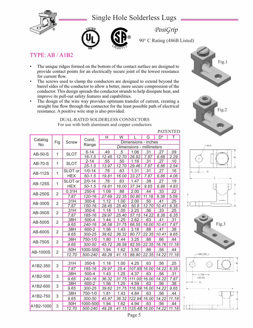
TYPE: AB / A1B2 • The unique ridges formed on the bottom of the contact surface are designed to
provide contact points for an electrically secure joint of the lowest resistance for current flow.
• The screws used to clamp the conductors are designed to extend beyond the barrel sides of the conductor to allow a better, more secure compression of the conductor. This design spreads the conductor strands to help dissipate heat, and improve its pull-out safety features and capabilities.
• The design of the wire way provides optimum transfer of current, creating a straight line flow through the connector for the least possible path of electrical resistance. A positive wire stop is also provided.
PATENTED
Single Hole Solderless LugsPosiGrip
90° C Rating (486B Listed)
Catalog No Fig Screw Cond.
Range
H W L G D* TDimensions - inches
Dimensions - millimeters
AB-50-S 1 SLOT 6-14 .49 .5 1.06 .31 .27 .0916-1.5 12.45 12.70 26.92 7.87 6.68 2.29
AB-70-S 1 SLOT 2-14 .55 .50 1.16 .31 .27 .1025-1.5 13.97 12.70 29.46 7.87 6.86 2.54
AB-112S 1 SLOT or HEX
1/0-14 .78 .63 1.31 .31 .27 .1650-1.5 19.81 16.00 33.27 7.87 6.86 4.06
AB-125S 1 SLOT or HEX
2/0-14 .78 .63 1.47 .38 .27 .1950-1.5 19.81 16.00 37.34 9.65 6.86 4.83
AB-250S 2 0.31H 250-6 1.09 .88 2.00 .44 .33 .227.87 120-16 27.69 22.35 50.80 11.18 8.38 5.59
AB-300S 2 .31H 300-6 1.12 1.00 2.00 .50 .41 .257.87 150-16 28.45 25.40 50.8 12.70 10.41 6.35
AB-350S 2 .31H 350-6 1.18 1.00 2.25 .56 .33 .257.87 185-16 29.97 25.40 57.15 14.22 8.38 6.35
AB-500S 2 .38H 500-4 1.44 1.25 2.62 .63 .41 .319.65 240-16 36.58 31.75 66.55 16.00 10.41 7.87
AB-600S 2 .38H 600-2 1.56 1.43 3.18 .88 .41 .389.65 300-25 39.62 36.32 80.77 22.35 10.41 9.65
AB-750S 2 .38H 750-1/0 1.80 1.44 3.25 .88 .66 .449.65 300-50 45.72 36.58 82.55 22.35 16.76 11.18
AB-1000S 2 .50H 1000-500 1.94 1.62 3.50 .88 .56 .4412.70 500-240 49.28 41.15 88.90 22.35 14.22 11.18
A1B2-350 3 .31H 350-6 1.18 1.00 4.25 .63 .56 .257.87 185-16 29.97 25.4 107.95 16.00 14.22 6.35
A1B2-500 3 .38H 500-4 1.43 1.25 4.37 .63 .56 .319.65 240-16 36.32 31.75 111.00 16.00 14.22 7.87
A1B2-600 3 .38H 600-2 1.56 1.25 4.59 .63 .56 .389.65 300-25 39.62 31.75 116.59 16.00 14.22 9.65
A1B2-750 3 .38H 750-1/0 1.81 1.43 4.84 .63 .56 .449.65 300-50 45.97 36.32 122.94 16.00 14.22 11.18
A1B2-1000 3 .50H 1000-500 1.94 1.62 4.94 .63 .56 .4412.70 500-240 49.28 41.15 125.48 16.00 14.22 11.18
Page 5
Fig.1
Fig.2
Fig.3
DUAL-RATED SOLDERLESS CONNECTORSFor use with both aluminum and copper conductors
Ø D
G
L
H
ØD (2PL.)
W
1.750(44.45)
G
L
HT
W
Catalog No Fig
ScrewTypemm
Cond. Range AWGmm²
H W L G D* T
Dimensions - inches
Dimensions - millimeters
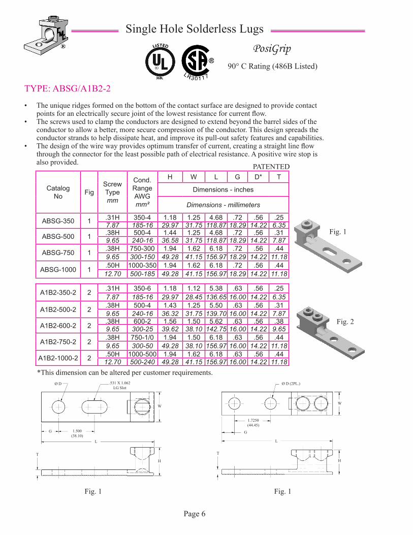
ABSG-350 1 .31H 350-4 1.18 1.25 4.68 .72 .56 .257.87 185-16 29.97 31.75 118.87 18.29 14.22 6.35
ABSG-500 1 .38H 500-4 1.44 1.25 4.68 .72 .56 .319.65 240-16 36.58 31.75 118.87 18.29 14.22 7.87
ABSG-750 1 .38H 750-300 1.94 1.62 6.18 .72 .56 .449.65 300-150 49.28 41.15 156.97 18.29 14.22 11.18
ABSG-1000 1 .50H 1000-350 1.94 1.62 6.18 .72 .56 .4412.70 500-185 49.28 41.15 156.97 18.29 14.22 11.18
A1B2-350-2 2 .31H 350-6 1.18 1.12 5.38 .63 .56 .257.87 185-16 29.97 28.45 136.65 16.00 14.22 6.35
A1B2-500-2 2 .38H 500-4 1.43 1.25 5.50 .63 .56 .319.65 240-16 36.32 31.75 139.70 16.00 14.22 7.87
A1B2-600-2 2 .38H 600-2 1.56 1.50 5.62 .63 .56 .389.65 300-25 39.62 38.10 142.75 16.00 14.22 9.65
A1B2-750-2 2 .38H 750-1/0 1.94 1.50 6.18 .63 .56 .449.65 300-50 49.28 38.10 156.97 16.00 14.22 11.18
A1B2-1000-2 2 .50H 1000-500 1.94 1.62 6.18 .63 .56 .4412.70 500-240 49.28 41.15 156.97 16.00 14.22 11.18
Page 6
Single Hole Solderless Lugs
TYPE: ABSG/A1B2-2
• The unique ridges formed on the bottom of the contact surface are designed to provide contact points for an electrically secure joint of the lowest resistance for current flow.
• The screws used to clamp the conductors are designed to extend beyond the barrel sides of the conductor to allow a better, more secure compression of the conductor. This design spreads the conductor strands to help dissipate heat, and improve its pull-out safety features and capabilities.
• The design of the wire way provides optimum transfer of current, creating a straight line flow through the connector for the least possible path of electrical resistance. A positive wire stop is also provided.
PosiGrip90° C Rating (486B Listed)
*This dimension can be altered per customer requirements.
Fig. 1
Fig. 2
Fig. 1 Fig. 1
PATENTED
Ø D .531 X 1.062LG Slot
W
G 1.500(38.10)
L
TH
T
L
G
1.7250(44.45)
H
W
Ø D (2PL.)
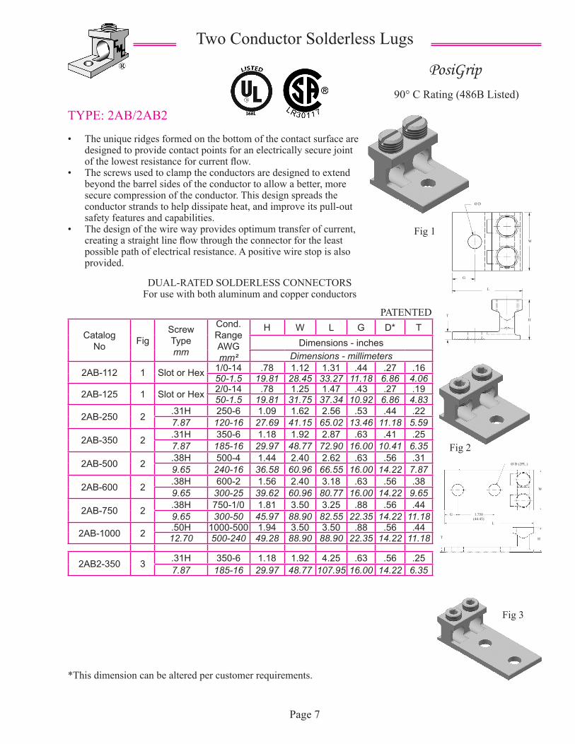
TYPE: 2AB/2AB2
• The unique ridges formed on the bottom of the contact surface are designed to provide contact points for an electrically secure joint of the lowest resistance for current flow.
• The screws used to clamp the conductors are designed to extend beyond the barrel sides of the conductor to allow a better, more secure compression of the conductor. This design spreads the conductor strands to help dissipate heat, and improve its pull-out safety features and capabilities.
• The design of the wire way provides optimum transfer of current, creating a straight line flow through the connector for the least possible path of electrical resistance. A positive wire stop is also provided.
PosiGrip90° C Rating (486B Listed)
Two Conductor Solderless Lugs
*This dimension can be altered per customer requirements.
DUAL-RATED SOLDERLESS CONNECTORSFor use with both aluminum and copper conductors
Page 7
Catalog No Fig
ScrewTypemm
Cond. Range AWGmm²
H W L G D* TDimensions - inches
Dimensions - millimeters
2AB-112 1 Slot or Hex 1/0-14 .78 1.12 1.31 .44 .27 .1650-1.5 19.81 28.45 33.27 11.18 6.86 4.06
2AB-125 1 Slot or Hex 2/0-14 .78 1.25 1.47 .43 .27 .1950-1.5 19.81 31.75 37.34 10.92 6.86 4.83
2AB-250 2 .31H 250-6 1.09 1.62 2.56 .53 .44 .227.87 120-16 27.69 41.15 65.02 13.46 11.18 5.59
2AB-350 2 .31H 350-6 1.18 1.92 2.87 .63 .41 .257.87 185-16 29.97 48.77 72.90 16.00 10.41 6.35
2AB-500 2 .38H 500-4 1.44 2.40 2.62 .63 .56 .319.65 240-16 36.58 60.96 66.55 16.00 14.22 7.87
2AB-600 2 .38H 600-2 1.56 2.40 3.18 .63 .56 .389.65 300-25 39.62 60.96 80.77 16.00 14.22 9.65
2AB-750 2 .38H 750-1/0 1.81 3.50 3.25 .88 .56 .449.65 300-50 45.97 88.90 82.55 22.35 14.22 11.18
2AB-1000 2 .50H 1000-500 1.94 3.50 3.50 .88 .56 .4412.70 500-240 49.28 88.90 88.90 22.35 14.22 11.18
2AB2-350 3 .31H 350-6 1.18 1.92 4.25 .63 .56 .257.87 185-16 29.97 48.77 107.95 16.00 14.22 6.35
PATENTED
Fig 1
Fig 2
Fig 3
Ø D
W
G
L
HT
Ø D (2PL.)
W
G 1.750(44.45)
L
HT
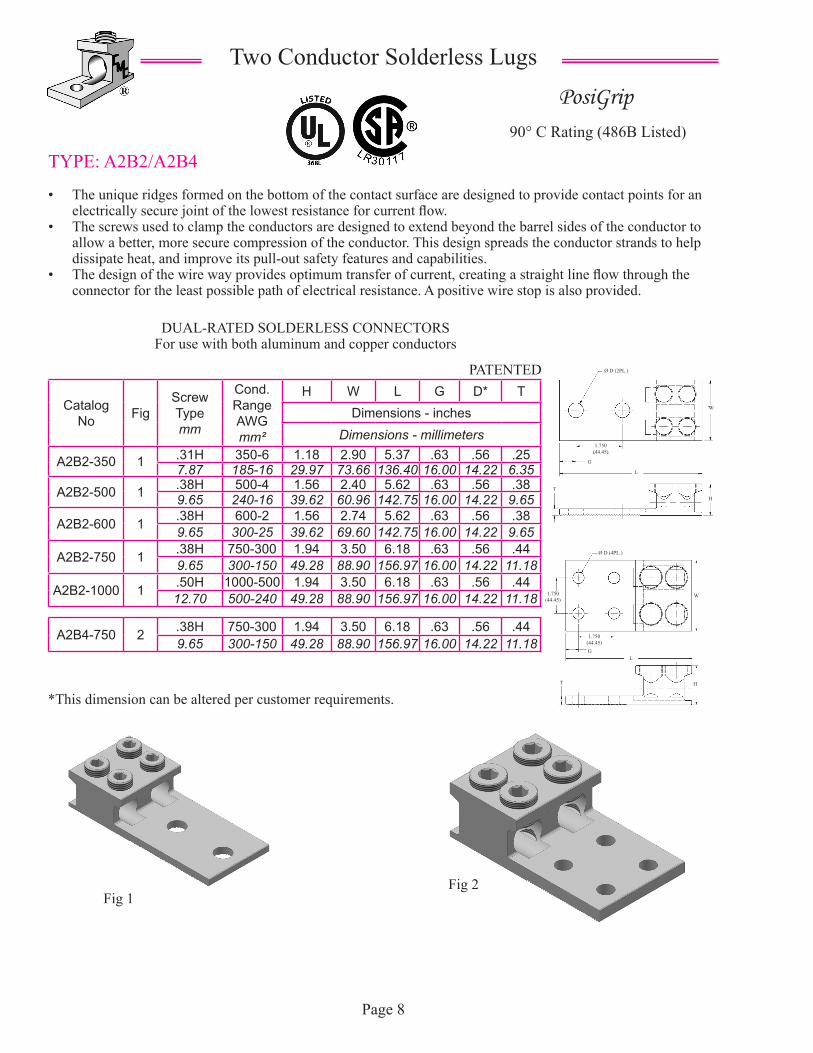
TYPE: A2B2/A2B4
• The unique ridges formed on the bottom of the contact surface are designed to provide contact points for an electrically secure joint of the lowest resistance for current flow.
• The screws used to clamp the conductors are designed to extend beyond the barrel sides of the conductor to allow a better, more secure compression of the conductor. This design spreads the conductor strands to help dissipate heat, and improve its pull-out safety features and capabilities.
• The design of the wire way provides optimum transfer of current, creating a straight line flow through the connector for the least possible path of electrical resistance. A positive wire stop is also provided.
PosiGrip90° C Rating (486B Listed)
Two Conductor Solderless Lugs
*This dimension can be altered per customer requirements.
DUAL-RATED SOLDERLESS CONNECTORSFor use with both aluminum and copper conductors
Page 8
Catalog No Fig
ScrewTypemm
Cond. Range AWGmm²
H W L G D* TDimensions - inches
Dimensions - millimeters
A2B2-350 1 .31H 350-6 1.18 2.90 5.37 .63 .56 .257.87 185-16 29.97 73.66 136.40 16.00 14.22 6.35
A2B2-500 1 .38H 500-4 1.56 2.40 5.62 .63 .56 .389.65 240-16 39.62 60.96 142.75 16.00 14.22 9.65
A2B2-600 1 .38H 600-2 1.56 2.74 5.62 .63 .56 .389.65 300-25 39.62 69.60 142.75 16.00 14.22 9.65
A2B2-750 1 .38H 750-300 1.94 3.50 6.18 .63 .56 .449.65 300-150 49.28 88.90 156.97 16.00 14.22 11.18
A2B2-1000 1 .50H 1000-500 1.94 3.50 6.18 .63 .56 .4412.70 500-240 49.28 88.90 156.97 16.00 14.22 11.18
A2B4-750 2 .38H 750-300 1.94 3.50 6.18 .63 .56 .449.65 300-150 49.28 88.90 156.97 16.00 14.22 11.18
PATENTED
Fig 1Fig 2
Ø D (2PL.)
1.750(44.45)
W
L
G
H
T
Ø D (4PL.)
W1.750(44.45)
1.750(44.45)G
L
HT
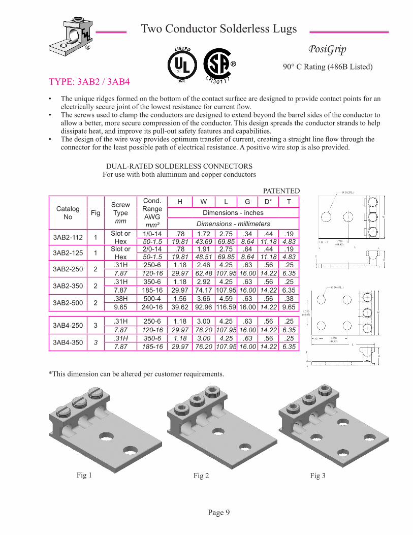
TYPE: 3AB2 / 3AB4
• The unique ridges formed on the bottom of the contact surface are designed to provide contact points for an electrically secure joint of the lowest resistance for current flow.
• The screws used to clamp the conductors are designed to extend beyond the barrel sides of the conductor to allow a better, more secure compression of the conductor. This design spreads the conductor strands to help dissipate heat, and improve its pull-out safety features and capabilities.
• The design of the wire way provides optimum transfer of current, creating a straight line flow through the connector for the least possible path of electrical resistance. A positive wire stop is also provided.
PosiGrip90° C Rating (486B Listed)
Two Conductor Solderless Lugs
*This dimension can be altered per customer requirements.
DUAL-RATED SOLDERLESS CONNECTORSFor use with both aluminum and copper conductors
Page 9
PATENTED
Fig 1 Fig 2 Fig 3
Catalog No Fig
ScrewTypemm
Cond. Range AWGmm²
H W L G D* TDimensions - inches
Dimensions - millimeters
3AB2-112 1 Slot or Hex
1/0-14 .78 1.72 2.75 .34 .44 .1950-1.5 19.81 43.69 69.85 8.64 11.18 4.83
3AB2-125 1 Slot or Hex
2/0-14 .78 1.91 2.75 .64 .44 .1950-1.5 19.81 48.51 69.85 8.64 11.18 4.83
3AB2-250 2 .31H 250-6 1.18 2.46 4.25 .63 .56 .257.87 120-16 29.97 62.48 107.95 16.00 14.22 6.35
3AB2-350 2 .31H 350-6 1.18 2.92 4.25 .63 .56 .257.87 185-16 29.97 74.17 107.95 16.00 14.22 6.35
3AB2-500 2 .38H 500-4 1.56 3.66 4.59 .63 .56 .389.65 240-16 39.62 92.96 116.59 16.00 14.22 9.65
3AB4-250 3 .31H 250-6 1.18 3.00 4.25 .63 .56 .257.87 120-16 29.97 76.20 107.95 16.00 14.22 6.35
3AB4-350 3 .31H 350-6 1.18 3.00 4.25 .63 .56 .257.87 185-16 29.97 76.20 107.95 16.00 14.22 6.35
1.750(44.45)
L
G
HT
Ø D (2PL.)
W
1.750(44.45)
1.750(44.45)
G
W
H
L
T
Ø D (4PL.)

TYPE: A3B2 / A3B4
• The unique ridges formed on the bottom of the contact surface are designed to provide contact points for an electrically secure joint of the lowest resistance for current flow.
• The screws used to clamp the conductors are designed to extend beyond the barrel sides of the conductor to allow a better, more secure compression of the conductor. This design spreads the conductor strands to help dissipate heat, and improve its pull-out safety features and capabilities.
• The design of the wire way provides optimum transfer of current, creating a straight line flow through the connector for the least possible path of electrical resistance. A positive wire stop is also provided.
PosiGrip90° C Rating (486B Listed)
Three Conductor Solderless Lugs
*This dimension can be altered per customer requirements.
DUAL-RATED SOLDERLESS CONNECTORSFor use with both aluminum and copper conductors
Page 10
PATENTED
Fig 1 Fig 2
Catalog No Fig
ScrewTypemm
Cond. Range AWGmm²
H W L G D* TDimensions - inches
Dimensions - millimeters
A3B2-600 1 .38H 600-2 1.56 4.18 5.62 .63 .56 .389.65 300-25 39.62 106.17 142.75 16.00 14.22 9.65
A3B2-750 1 .38H 750-300 1.94 4.86 6.18 .63 .56 .449.65 300-150 49.28 123.44 156.97 16.00 14.22 11.18
A3B2-1000 1 .50H 1000-500 1.94 4.86 6.18 .63 .56 .4412.70 500-240 49.28 123.44 156.97 16.00 14.22 11.18
A3B4-600 2 .38H 600-2 1.56 4.18 5.62 .63 .56 .389.65 300-25 39.62 106.17 142.75 16.00 14.22 9.65
A3B4-750 2 .38H 750-300 1.94 4.86 6.18 .63 .56 .449.65 300-150 49.28 123.44 156.97 16.00 14.22 11.18
1.750(44.45)
L
G
W
Ø D (4PL.)
T
1.750(44.45)
G
H
L
T
Ø D (2PL.)
H
W1.750(44.45)
Page 11
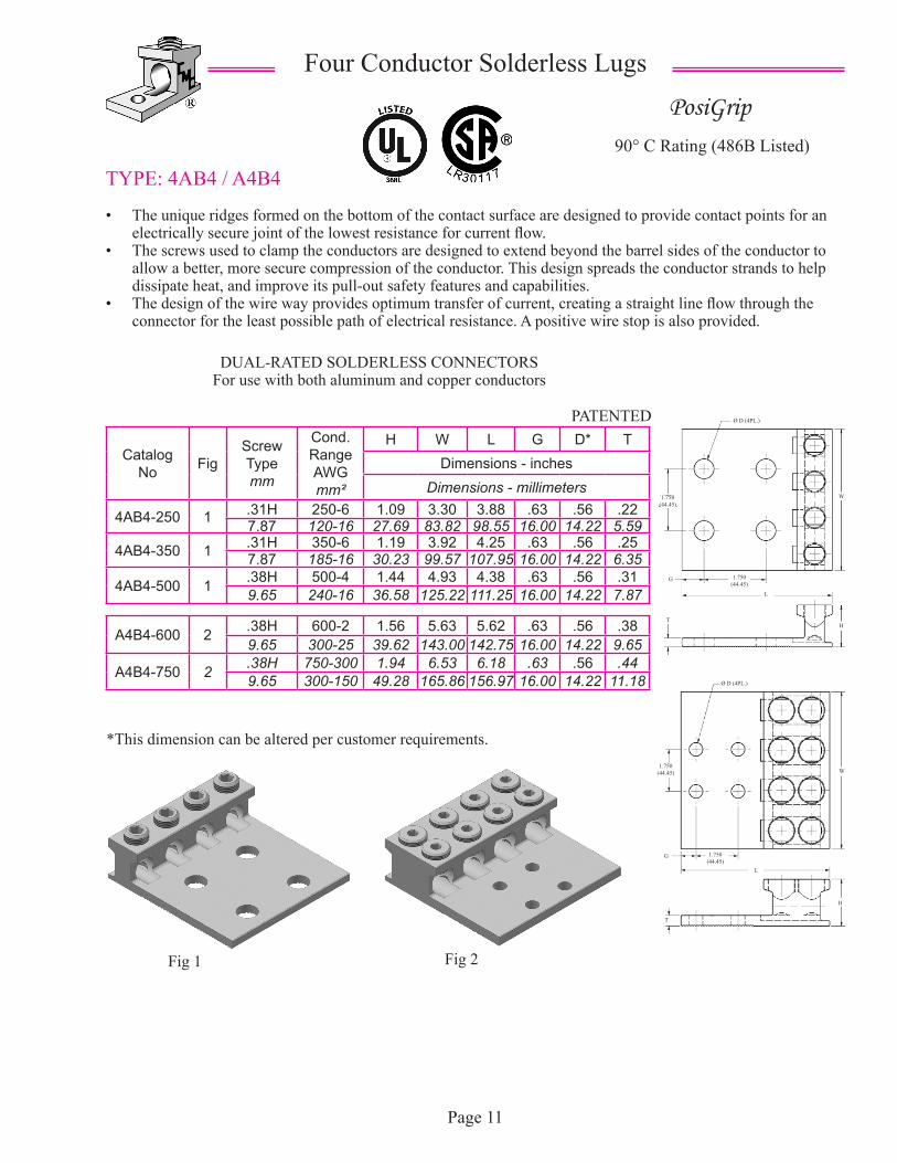
TYPE: 4AB4 / A4B4
• The unique ridges formed on the bottom of the contact surface are designed to provide contact points for an electrically secure joint of the lowest resistance for current flow.
• The screws used to clamp the conductors are designed to extend beyond the barrel sides of the conductor to allow a better, more secure compression of the conductor. This design spreads the conductor strands to help dissipate heat, and improve its pull-out safety features and capabilities.
• The design of the wire way provides optimum transfer of current, creating a straight line flow through the connector for the least possible path of electrical resistance. A positive wire stop is also provided.
PosiGrip90° C Rating (486B Listed)
Four Conductor Solderless Lugs
*This dimension can be altered per customer requirements.
DUAL-RATED SOLDERLESS CONNECTORSFor use with both aluminum and copper conductors
PATENTED
Fig 1 Fig 2
Catalog No Fig
ScrewTypemm
Cond. Range AWGmm²
H W L G D* TDimensions - inches
Dimensions - millimeters
4AB4-250 1 .31H 250-6 1.09 3.30 3.88 .63 .56 .227.87 120-16 27.69 83.82 98.55 16.00 14.22 5.59
4AB4-350 1 .31H 350-6 1.19 3.92 4.25 .63 .56 .257.87 185-16 30.23 99.57 107.95 16.00 14.22 6.35
4AB4-500 1 .38H 500-4 1.44 4.93 4.38 .63 .56 .319.65 240-16 36.58 125.22 111.25 16.00 14.22 7.87
A4B4-600 2 .38H 600-2 1.56 5.63 5.62 .63 .56 .389.65 300-25 39.62 143.00 142.75 16.00 14.22 9.65
A4B4-750 2 .38H 750-300 1.94 6.53 6.18 .63 .56 .449.65 300-150 49.28 165.86 156.97 16.00 14.22 11.18
1.750(44.45)
L
G
W
Ø D (4PL.)
T
1.750(44.45)
G
H
L
TH
W
1.750(44.45)
Ø D (4PL.)
1.750(44.45)
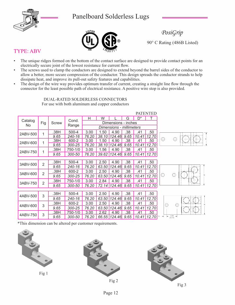
TYPE: ABV
• The unique ridges formed on the bottom of the contact surface are designed to provide contact points for an electrically secure joint of the lowest resistance for current flow.
• The screws used to clamp the conductors are designed to extend beyond the barrel sides of the conductor to allow a better, more secure compression of the conductor. This design spreads the conductor strands to help dissipate heat, and improve its pull-out safety features and capabilities.
• The design of the wire way provides optimum transfer of current, creating a straight line flow through the connector for the least possible path of electrical resistance. A positive wire stop is also provided.
PosiGrip90° C Rating (486B Listed)
Panelboard Solderless Lugs
*This dimension can be altered per customer requirements.
DUAL-RATED SOLDERLESS CONNECTORSFor use with both aluminum and copper conductors
PATENTED
Fig 1
Fig 2
Catalog No Fig Screw Cond.
Range
H W L G D* TDimensions - inches
Dimensions - millimeters
2ABV-500 1 .38H 500-4 3.00 1.50 4.90 .38 .41 .509.65 240-16 76.20 38.10 124.46 9.65 10.41 12.70
2ABV-600 1 .38H 600-2 3.00 1.50 4.90 .38 .41 .509.65 300-25 76.20 38.10 124.46 9.65 10.41 12.70
2ABV-750 1 .38H 750-1/0 3.00 1.56 4.90 .38 .41 .509.65 300-50 76.20 39.62 124.46 9.65 10.41 12.70
3ABV-500 2 .38H 500-4 3.00 2.50 4.90 .38 .41 .509.65 240-16 76.20 63.50 124.46 9.65 10.41 12.70
3ABV-600 2 .38H 600-2 3.00 2.50 4.90 .38 .41 .509.65 300-25 76.20 63.50 124.46 9.65 10.41 12.70
3ABV-750 2 .38H 750-1/0 3.00 2.84 4.90 .38 .41 .509.65 300-50 76.20 72.14 124.46 9.65 10.41 12.70
4ABV-500 3 .38H 500-4 3.00 2.50 4.90 .38 .41 .509.65 240-16 76.20 63.50 124.46 9.65 10.41 12.70
4ABV-600 3 .38H 600-2 3.00 2.50 4.90 .38 .41 .509.65 300-25 76.20 63.50 124.46 9.65 10.41 12.70
4ABV-750 3 .38H 750-1/0 3.00 2.62 4.90 .38 .41 .509.65 300-50 76.20 66.55 124.46 9.65 10.41 12.70
Fig 3
Page 12
W
1.250(31.75)
G
W
W
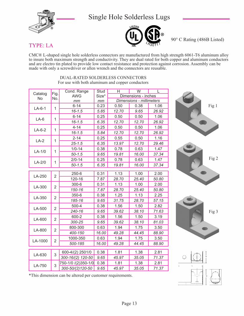
TYPE: LA
CMC® L-shaped single hole solderless connectors are manufactured from high strength 6061-T6 aluminum alloy to insure both maximum strength and conductivity. They are dual rated for both copper and aluminum conductors and are electro tin plated to provide low contact resistance and protection against corrosion. Assembly can be made with only a screwdriver or allen wrench and the connectors are reusable.
90° C Rating (486B Listed)
Single Hole Solderless Lugs
DUAL-RATED SOLDERLESS CONNECTORSFor use with both aluminum and copper conductors
Fig 1
Catalog No
Fig.No.
Cond. RangeAWGmm
Stud Size*mm
H W LDimensions - inches
Dimensions - millimeters
LA-6-1 16-14 0.23 0.50 0.38 1.06
16-1.5 5.85 12.70 9.65 26.92
LA-6 16-14 0.25 0.50 0.50 1.06
16-1.5 6.35 12.70 12.70 26.92
LA-6-2 14-14 0.25 0.50 0.50 1.06
16-1.5 5.84 12.70 12.70 26.92
LA-2 12-14 0.25 0.55 0.50 1.16
25-1.5 6.35 13.97 12.70 29.46
LA-1/0 11/0-14 0.38 0.78 0.63 1.4750-1.5 9.65 19.81 16.00 37.34
LA-2/0 12/0-14 0.25 0.78 0.63 1.4750-1.5 6.35 19.81 16.00 37.34
LA-250 2250-6 0.31 1.13 1.00 2.00
120-16 7.87 28.70 25.40 50.80
LA-300 2300-6 0.31 1.13 1.00 2.00
150-16 7.87 28.70 25.40 50.80
LA-350 2350-6 0.38 1.25 1.13 2.25
185-16 9.65 31.75 28.70 57.15
LA-500 2500-4 0.38 1.56 1.50 2.82
240-16 9.65 39.62 38.10 71.63
LA-600 2600-2 0.38 1.56 1.50 3.19
300-25 9.65 39.62 38.10 81.03
LA-800 2800-300 0.63 1.94 1.75 3.50400-150 16.00 49.28 44.45 88.90
LA-1000 21000-350 0.63 1.94 1.75 3.50500-185 16.00 49.28 44.45 88.90
LA-630 3600-4/(2) 2501/0 0.38 1.81 1.38 2.81
300-16/(2) 120-50 9.65 45.97 35.05 71.37
LA-750 3750-1/0 /(2)350-1/0 0.38 1.81 1.38 2.81300-50/(2)120-50 9.65 45.97 35.05 71.37
Page 13
Fig 2
Fig 3
*This dimension can be altered per customer requirements.
L
H
W
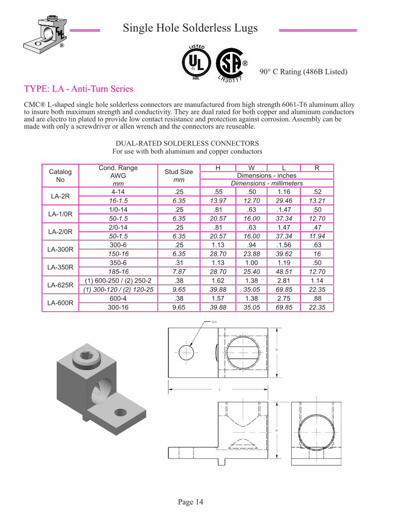
TYPE: LA - Anti-Turn Series
CMC® L-shaped single hole solderless connectors are manufactured from high strength 6061-T6 aluminum alloy to insure both maximum strength and conductivity. They are dual rated for both copper and aluminum conductors and are electro tin plated to provide low contact resistance and protection against corrosion. Assembly can be made with only a screwdriver or allen wrench and the connectors are reuseable.
90° C Rating (486B Listed)
Single Hole Solderless Lugs
DUAL-RATED SOLDERLESS CONNECTORSFor use with both aluminum and copper conductors
Catalog No
Cond. RangeAWGmm
Stud Sizemm
H W L RDimensions - inches
Dimensions - millimeters
LA-2R4-14 .25 .55 .50 1.16 .52
16-1.5 6.35 13.97 12.70 29.46 13.21
LA-1/0R1/0-14 .25 .81 .63 .1.47 .5050-1.5 6.35 20.57 16.00 37.34 12.70
LA-2/0R 2/0-14 .25 .81 .63 1.47 .4750-1.5 6.35 20.57 16.00 37.34 11.94
LA-300R300-6 .25 1.13 .94 .1.56 .63
150-16 6.35 28.70 23.88 39.62 16
LA-350R350-6 .31 1.13 1.00 1.19 .50
185-16 7.87 28.70 25.40 48.51 12.70
LA-625R(1) 600-250 / (2) 250-2 .38 1.62 1.38 2.81 1.14
(1) 300-120 / (2) 120-25 9.65 39.88 35.05 69.85 22.35
LA-600R600-4 .38 1.57 1.38 2.75 .88
300-16 9.65 39.88 35.05 69.85 22.35
Page 14
Ø D
W
L
H
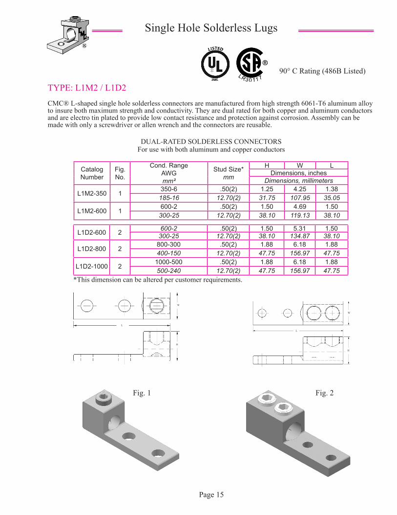
TYPE: L1M2 / L1D2
CMC® L-shaped single hole solderless connectors are manufactured from high strength 6061-T6 aluminum alloy to insure both maximum strength and conductivity. They are dual rated for both copper and aluminum conductors and are electro tin plated to provide low contact resistance and protection against corrosion. Assembly can be made with only a screwdriver or allen wrench and the connectors are reusable.
90° C Rating (486B Listed)
Single Hole Solderless Lugs
DUAL-RATED SOLDERLESS CONNECTORSFor use with both aluminum and copper conductors
Catalog Number
Fig. No.
Cond. RangeAWGmm²
Stud Size*mm
H W LDimensions, inches
Dimensions, millimeters
L1M2-350 1350-6 .50(2) 1.25 4.25 1.38
185-16 12.70(2) 31.75 107.95 35.05
L1M2-600 1600-2 .50(2) 1.50 4.69 1.50
300-25 12.70(2) 38.10 119.13 38.10
Page 15
L1D2-600 2 600-2 .50(2) 1.50 5.31 1.50300-25 12.70(2) 38.10 134.87 38.10
L1D2-800 2800-300 .50(2) 1.88 6.18 1.88400-150 12.70(2) 47.75 156.97 47.75
L1D2-1000 21000-500 .50(2) 1.88 6.18 1.88500-240 12.70(2) 47.75 156.97 47.75
*This dimension can be altered per customer requirements.
Fig. 1 Fig. 2
H
W
L
H
W
L
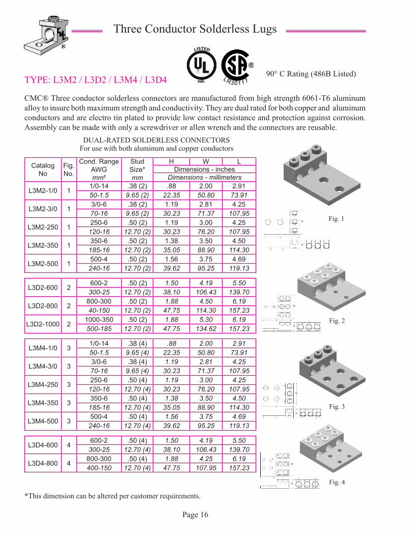
TYPE: L3M2 / L3D2 / L3M4 / L3D4
CMC® Three conductor solderless connectors are manufactured from high strength 6061-T6 aluminum alloy to insure both maximum strength and conductivity. They are dual rated for both copper and aluminum conductors and are electro tin plated to provide low contact resistance and protection against corrosion. Assembly can be made with only a screwdriver or allen wrench and the connectors are reusable.
90° C Rating (486B Listed)
Three Conductor Solderless Lugs
DUAL-RATED SOLDERLESS CONNECTORSFor use with both aluminum and copper conductors
Page 16
*This dimension can be altered per customer requirements.
Catalog No
Fig. No.
Cond. RangeAWGmm²
Stud Size*mm
H W LDimensions - inches
Dimensions - millimeters
L3M2-1/0 11/0-14 .38 (2) .88 2.00 2.9150-1.5 9.65 (2) 22.35 50.80 73.91
L3M2-3/0 13/0-6 .38 (2) 1.19 2.81 4.2570-16 9.65 (2) 30.23 71.37 107.95
L3M2-250 1250-6 .50 (2) 1.19 3.00 4.25
120-16 12.70 (2) 30.23 76.20 107.95
L3M2-350 1350-6 .50 (2) 1.38 3.50 4.50
185-16 12.70 (2) 35.05 88.90 114.30
L3M2-500 1500-4 .50 (2) 1.56 3.75 4.69
240-16 12.70 (2) 39.62 95.25 119.13
L3D2-600 2600-2 .50 (2) 1.50 4.19 5.50
300-25 12.70 (2) 38.10 106.43 139.70
L3D2-800 2800-300 .50 (2) 1.88 4.50 6.1940-150 12.70 (2) 47.75 114.30 157.23
L3D2-1000 21000-350 .50 (2) 1.88 5.30 6.19500-185 12.70 (2) 47.75 134.62 157.23
L3M4-1/0 31/0-14 .38 (4) .88 2.00 2.9150-1.5 9.65 (4) 22.35 50.80 73.91
L3M4-3/0 33/0-6 .38 (4) 1.19 2.81 4.2570-16 9.65 (4) 30.23 71.37 107.95
L3M4-250 3250-6 .50 (4) 1.19 3.00 4.25
120-16 12.70 (4) 30.23 76.20 107.95
L3M4-350 3350-6 .50 (4) 1.38 3.50 4.50
185-16 12.70 (4) 35.05 88.90 114.30
L3M4-500 3500-4 .50 (4) 1.56 3.75 4.69
240-16 12.70 (4) 39.62 95.25 119.13
L3D4-600 4600-2 .50 (4) 1.50 4.19 5.50
300-25 12.70 (4) 38.10 106.43 139.70
L3D4-800 4800-300 .50 (4) 1.88 4.25 6.19400-150 12.70 (4) 47.75 107.95 157.23
Fig. 2
Fig. 3
Fig. 4
Fig. 1
L
W
H
H
W
L
H
W
L
H
W
L
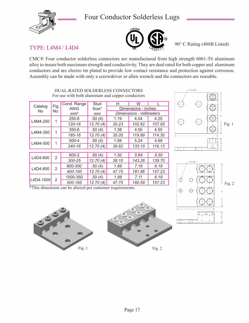
TYPE: L4M4 / L4D4
CMC® Four conductor solderless connectors are manufactured from high strength 6061-T6 aluminum alloy to insure both maximum strength and conductivity. They are dual rated for both copper and aluminum conductors and are electro tin plated to provide low contact resistance and protection against corrosion. Assembly can be made with only a screwdriver or allen wrench and the connectors are reusable.
90° C Rating (486B Listed)
Four Conductor Solderless Lugs
DUAL-RATED SOLDERLESS CONNECTORSFor use with both aluminum and copper conductors
Page 17
*This dimension can be altered per customer requirements.
Catalog No
Fig. No.
Cond. RangeAWGmm²
Stud Size*mm
H W LDimensions - inches
Dimensions - millimeters
L4M4-250 1250-6 .50 (4) 1.19 4.04 4.25
120-16 12.70 (4) 30.23 102.62 107.95
L4M4-350 1350-6 .50 (4) 1.38 4.50 4.50
185-16 12.70 (4) 35.05 119.89 114.30
L4M4-500 1500-4 .50 (4) 1.56 5.24 4.69
240-16 12.70 (4) 39.62 133.10 119.13
L4D4-600 2600-2 .50 (4) 1.50 5.64 5.50
300-25 12.70 (4) 38.10 143.26 139.70
L4D4-800 2800-300 .50 (4) 1.88 7.16 6.19400-150 12.70 (4) 47.75 181.86 157.23
L4D4-1000 21000-350 .50 (4) 1.88 7.11 6.19500-185 12.70 (4) 47.75 180.59 157.23
Fig. 1 Fig. 2
Fig. 1
Fig. 2
Ø D (4PL.)
W
L
H
W
Ø D (4PL.)
H
L
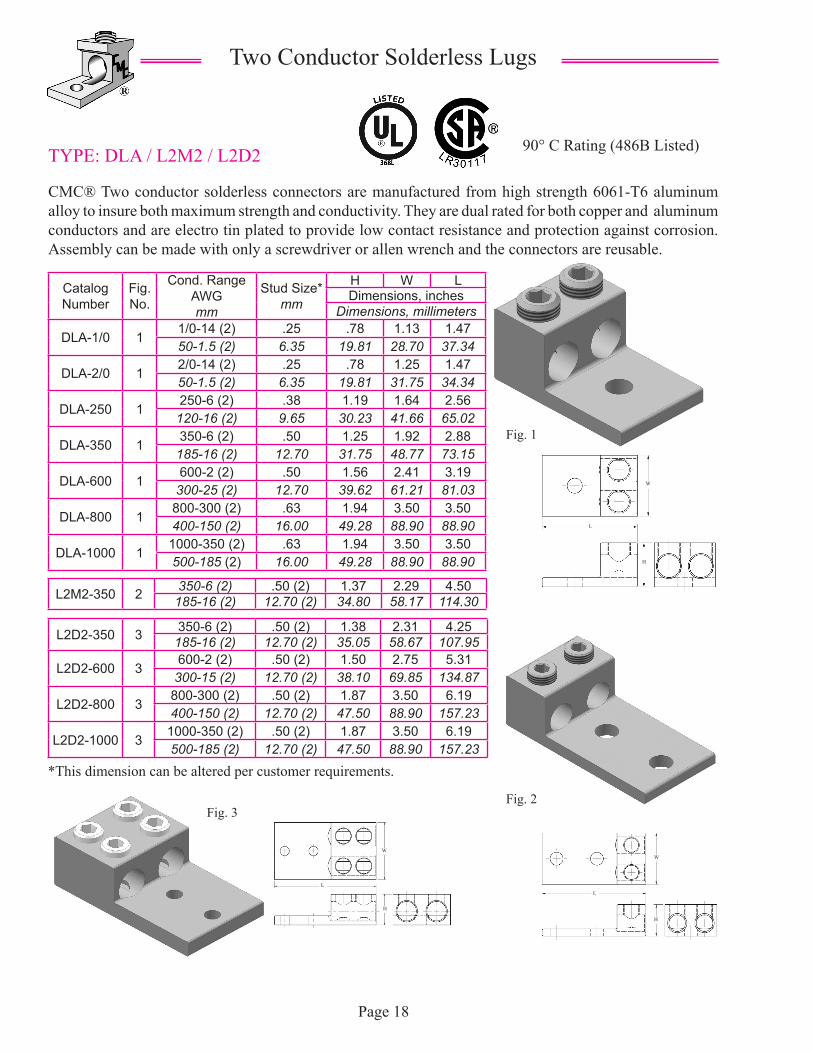
TYPE: DLA / L2M2 / L2D2
CMC® Two conductor solderless connectors are manufactured from high strength 6061-T6 aluminum alloy to insure both maximum strength and conductivity. They are dual rated for both copper and aluminum conductors and are electro tin plated to provide low contact resistance and protection against corrosion. Assembly can be made with only a screwdriver or allen wrench and the connectors are reusable.
90° C Rating (486B Listed)
Two Conductor Solderless Lugs
Catalog Number
Fig. No.
Cond. RangeAWGmm
Stud Size*mm
H W LDimensions, inches
Dimensions, millimeters
DLA-1/0 11/0-14 (2) .25 .78 1.13 1.4750-1.5 (2) 6.35 19.81 28.70 37.34
DLA-2/0 12/0-14 (2) .25 .78 1.25 1.4750-1.5 (2) 6.35 19.81 31.75 34.34
DLA-250 1250-6 (2) .38 1.19 1.64 2.56
120-16 (2) 9.65 30.23 41.66 65.02
DLA-350 1350-6 (2) .50 1.25 1.92 2.88
185-16 (2) 12.70 31.75 48.77 73.15
DLA-600 1600-2 (2) .50 1.56 2.41 3.19
300-25 (2) 12.70 39.62 61.21 81.03
DLA-800 1800-300 (2) .63 1.94 3.50 3.50400-150 (2) 16.00 49.28 88.90 88.90
DLA-1000 11000-350 (2) .63 1.94 3.50 3.50500-185 (2) 16.00 49.28 88.90 88.90
Page 18
L2M2-350 2 350-6 (2) .50 (2) 1.37 2.29 4.50185-16 (2) 12.70 (2) 34.80 58.17 114.30
L2D2-350 3 350-6 (2) .50 (2) 1.38 2.31 4.25185-16 (2) 12.70 (2) 35.05 58.67 107.95
L2D2-600 3600-2 (2) .50 (2) 1.50 2.75 5.31
300-15 (2) 12.70 (2) 38.10 69.85 134.87
L2D2-800 3800-300 (2) .50 (2) 1.87 3.50 6.19400-150 (2) 12.70 (2) 47.50 88.90 157.23
L2D2-1000 31000-350 (2) .50 (2) 1.87 3.50 6.19500-185 (2) 12.70 (2) 47.50 88.90 157.23
Fig. 1
Fig. 2Fig. 3
*This dimension can be altered per customer requirements.
H
W
L
W
H
LL
W
H
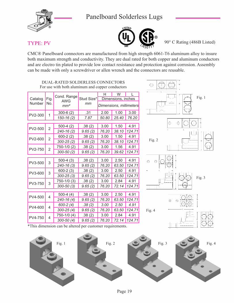
TYPE: PV
CMC® Panelboard connectors are manufactured from high strength 6061-T6 aluminum alloy to insure both maximum strength and conductivity. They are dual rated for both copper and aluminum conductors and are electro tin plated to provide low contact resistance and protection against corrosion. Assembly can be made with only a screwdriver or allen wrench and the connectors are reusable.
90° C Rating (486B Listed)
Panelboard Solderless Lugs
Catalog Number
Fig. No.
Cond. RangeAWGmm²
Stud Size*mm
H W LDimensions, inches
Dimensions, millimeters
PV2-300 1300-6 (2) .31 2.00 1.00 3.00
150-16 (2) 7.87 50.80 25.40 76.20
PV2-500 2500-4 (2) .38 (2) 3.00 1.50 4.91
240-16 (2) 9.65 (2) 76.20 38.10 124.71
PV2-600 2600-2 (2) .38 (2) 3.00 1.50 4.91
300-25 (2) 9.65 (2) 76.20 38.10 124.71
PV2-750 2750-1/0 (2) .38 (2) 3.00 1.56 4.91300-50 (2) 9.65 (2) 76.20 39.62 124.71
PV3-500 3500-4 (3) .38 (2) 3.00 2.50 4.91
240-16 (3) 9.65 (2) 76.20 63.50 124.71
PV3-600 3600-2 (3) .38 (2) 3.00 2.50 4.91
300-25 (3) 9.65 (2) 76.20 63.50 124.71
PV3-750 3750-1/0 (3) .38 (2) 3.00 2.84 4.91300-50 (3) 9.65 (2) 76.20 72.14 124.71
PV4-500 4500-4 (4) .38 (2) 3.00 2.50 4.91
240-16 (4) 9.65 (2) 76.20 63.50 124.71
PV4-600 4600-2 (4) .38 (2) 3.00 2.50 4.91
300-25 (4) 9.65 (2) 76.20 63.50 124.71
PV4-750 4750-1/0 (4) .38 (2) 3.00 2.84 4.91300-50 (4) 9.65 (2) 76.20 72.14 124.71
Page 19
Fig. 1
Fig. 2
Fig. 3
DUAL-RATED SOLDERLESS CONNECTORSFor use with both aluminum and copper conductors
Fig. 4
Fig. 1 Fig. 2 Fig. 3 Fig. 4
*This dimension can be altered per customer requirements.
H
H
L
W
L
W
W
H
L
H
L
W

TYPE: SG
CMC® Switchgear connectors are manufactured from high strength 6061-T6 aluminum alloy to insure both maximum strength and conductivity. They are dual rated for both copper and aluminum conductors and are electro tin plated to provide low contact resistance and protection against corrosion. Designed with slotted mounting holes on 350MCM and above for varied mounting arrangements.
90° C Rating (486B Listed)
Switchgear Connectors andGrounding Connectors
Catalog Number
Fig. No.
Cond. RangeAWGmm²
Stud Size*mm
H W LDimensions, inches
Dimensions, millimeters
SG-250 1250-3/0 .38 (2) 1.18 1.00 3.00120-70 9.65 (2) 29.97 25.40 76.20
SG-350 1350-1/0 .50 (2) 1.56 1.25 4.69185-50 12.70 (2) 39.62 31.75 119.13
SG-500 1500-2 .50 (2) 1.56 1.25 4.69
240-25 12.70 (2) 39.62 31.75 119.13
SG-800 1800-350 .50 (2) 1.88 1.62 6.19400-185 12.70 (2) 47.75 41.15 157.23
SG-1000 11000-350 .50 (2) 1.88 1.62 6.19500-185 12.70 (2) 47.75 41.15 157.23
Page 20
DUAL-RATED SOLDERLESS CONNECTORSFor use with both aluminum and copper conductors
*This dimension can be altered per customer requirements.
TYPE: LI Lay-In Connector
CMC® LI-S ground connectors are manufactured from high strength 6061-T6 aluminum alloy to insure both maximum strength and conductivity. They are dual rated for both copper and aluminum conductors and are electro tin plated to provide low contact resistance and protection against corrosion. They are designed for use on conduit grounding bushings. The open-faced design allows the installer to quickly ay-in the grounding conductor as a jumper to multiple conduits with no break in the ground conductor.
90° C Rating (486B Listed)
DUAL-RATED SOLDERLESS CONNECTORSFor use with both aluminum and copper conductors
Catalog Number
Fig. No.
Cond. RangeAWGmm²
Stud Size*mm
H W LDimensions, inches
Dimensions, millimeters
LI-50S 14-14 .22 .78 .38 1.07
16-1.5 5.59 19.81 9.65 27.18
LI-112S 11/0-14 .27 1.17 .60 1.5050-1.5 6.86 29.72 15.24 38.10
LI-200S 23/0-6 .33 1.56 .80 2.0070-16 8.38 39.62 20.32 50.80
LI-252S 2250-6 .33 1.79 .80 2.20
120-16 8.38 45.47 20.32 55.88*This dimension can be altered per customer requirements.
Fig. 1
Fig. 1 Fig. 2
H
W
L
H
L
W
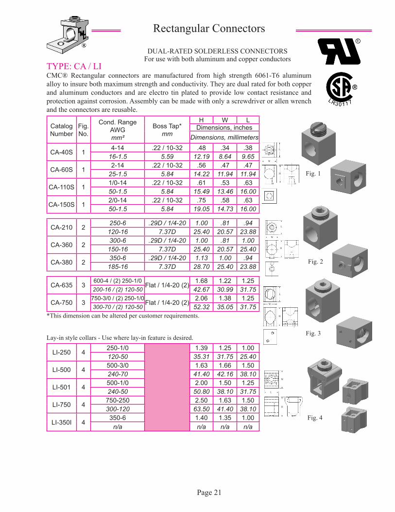
TYPE: CA / LICMC® Rectangular connectors are manufactured from high strength 6061-T6 aluminum alloy to insure both maximum strength and conductivity. They are dual rated for both copper and aluminum conductors and are electro tin plated to provide low contact resistance and protection against corrosion. Assembly can be made with only a screwdriver or allen wrench and the connectors are reusable.
Rectangular Connectors
Catalog Number
Fig. No.
Cond. RangeAWGmm²
Boss Tap*mm
H W LDimensions, inches
Dimensions, millimeters
CA-40S 14-14 .22 / 10-32 .48 .34 .38
16-1.5 5.59 12.19 8.64 9.65
CA-60S 12-14 .22 / 10-32 .56 .47 .47
25-1.5 5.84 14.22 11.94 11.94
CA-110S 11/0-14 .22 / 10-32 .61 .53 .6350-1.5 5.84 15.49 13.46 16.00
CA-150S 12/0-14 .22 / 10-32 .75 .58 .6350-1.5 5.84 19.05 14.73 16.00
CA-210 2250-6 .29D / 1/4-20 1.00 .81 .94
120-16 7.37D 25.40 20.57 23.88
CA-360 2300-6 .29D / 1/4-20 1.00 .81 1.00
150-16 7.37D 25.40 20.57 25.40
CA-380 2350-6 .29D / 1/4-20 1.13 1.00 .94
185-16 7.37D 28.70 25.40 23.88
CA-635 3600-4 / (2) 250-1/0
Flat / 1/4-20 (2)1.68 1.22 1.25
200-16 / (2) 120-50 42.67 30.99 31.75
CA-750 3750-3/0 / (2) 250-1/0
Flat / 1/4-20 (2)2.06 1.38 1.25
300-70 / (2) 120-50 52.32 35.05 31.75
LI-250 4250-1/0 1.39 1.25 1.00120-50 35.31 31.75 25.40
LI-500 4500-3/0 1.63 1.66 1.50240-70 41.40 42.16 38.10
LI-501 4500-1/0 2.00 1.50 1.25240-50 50.80 38.10 31.75
LI-750 4750-250 2.50 1.63 1.50300-120 63.50 41.40 38.10
LI-350I 4350-6 1.40 1.35 1.00
n/a n/a n/a n/a
Page 21
Fig. 1
Fig. 2
DUAL-RATED SOLDERLESS CONNECTORSFor use with both aluminum and copper conductors
Fig. 3
Fig. 4
*This dimension can be altered per customer requirements.
Lay-in style collars - Use where lay-in feature is desired.
H
L
W
H
W
L
H
W
L
H
W
L
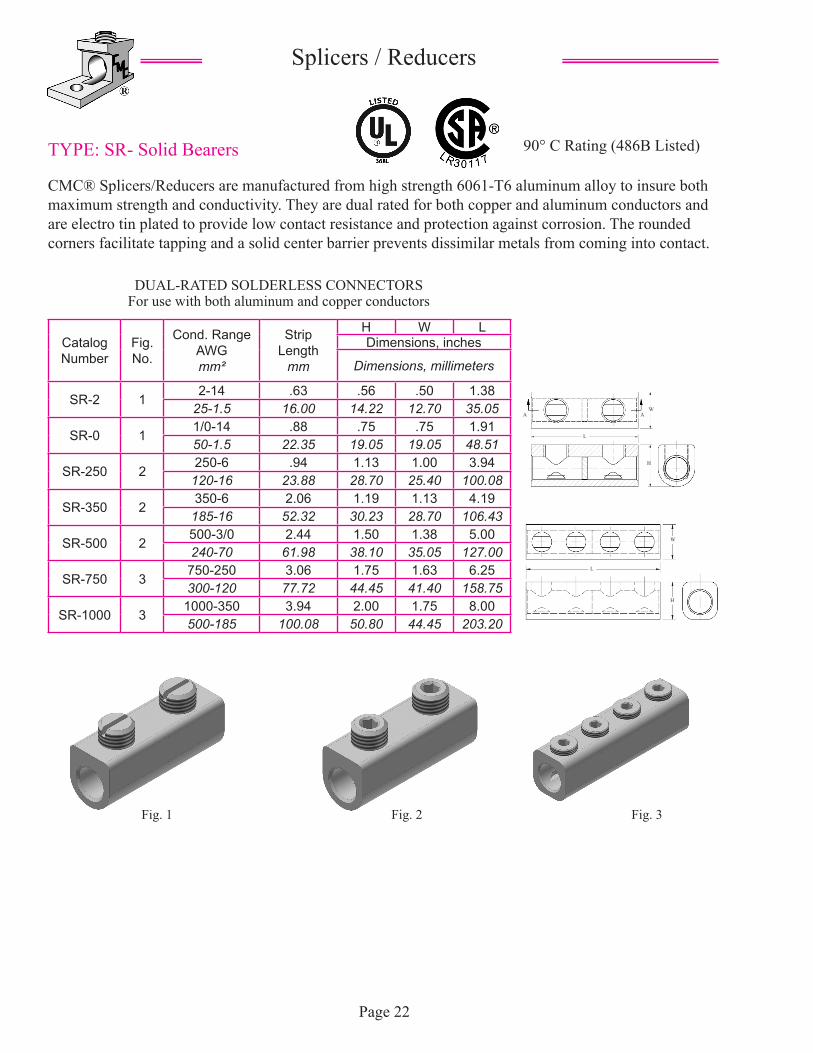
TYPE: SR- Solid Bearers
CMC® Splicers/Reducers are manufactured from high strength 6061-T6 aluminum alloy to insure both maximum strength and conductivity. They are dual rated for both copper and aluminum conductors and are electro tin plated to provide low contact resistance and protection against corrosion. The rounded corners facilitate tapping and a solid center barrier prevents dissimilar metals from coming into contact.
90° C Rating (486B Listed)
Splicers / Reducers
Catalog Number
Fig. No.
Cond. RangeAWGmm²
Strip Length
mm
H W LDimensions, inches
Dimensions, millimeters
SR-2 12-14 .63 .56 .50 1.38
25-1.5 16.00 14.22 12.70 35.05
SR-0 11/0-14 .88 .75 .75 1.9150-1.5 22.35 19.05 19.05 48.51
SR-250 2250-6 .94 1.13 1.00 3.94
120-16 23.88 28.70 25.40 100.08
SR-350 2350-6 2.06 1.19 1.13 4.19
185-16 52.32 30.23 28.70 106.43
SR-500 2500-3/0 2.44 1.50 1.38 5.00240-70 61.98 38.10 35.05 127.00
SR-750 3750-250 3.06 1.75 1.63 6.25300-120 77.72 44.45 41.40 158.75
SR-1000 31000-350 3.94 2.00 1.75 8.00500-185 100.08 50.80 44.45 203.20
Page 22
Fig. 1 Fig. 3
DUAL-RATED SOLDERLESS CONNECTORSFor use with both aluminum and copper conductors
Fig. 2
H
H
L
L
W
W
A A
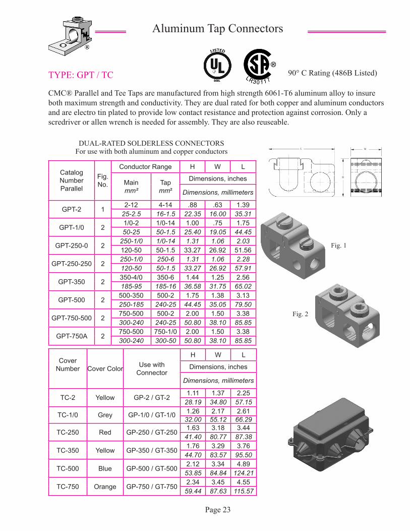
TYPE: GPT / TC
CMC® Parallel and Tee Taps are manufactured from high strength 6061-T6 aluminum alloy to insure both maximum strength and conductivity. They are dual rated for both copper and aluminum conductors and are electro tin plated to provide low contact resistance and protection against corrosion. Only a scredriver or allen wrench is needed for assembly. They are also reuseable.
90° C Rating (486B Listed)
Aluminum Tap Connectors
Catalog NumberParallel
Fig. No.
Conductor Range H W L
Mainmm²
Tapmm²
Dimensions, inches
Dimensions, millimeters
GPT-2 12-12 4-14 .88 .63 1.39
25-2.5 16-1.5 22.35 16.00 35.31
GPT-1/0 21/0-2 1/0-14 1.00 .75 1.7550-25 50-1.5 25.40 19.05 44.45
GPT-250-0 2250-1/0 1/0-14 1.31 1.06 2.03120-50 50-1.5 33.27 26.92 51.56
GPT-250-250 2250-1/0 250-6 1.31 1.06 2.28120-50 50-1.5 33.27 26.92 57.91
GPT-350 2350-4/0 350-6 1.44 1.25 2.56185-95 185-16 36.58 31.75 65.02
GPT-500 2500-350 500-2 1.75 1.38 3.13250-185 240-25 44.45 35.05 79.50
GPT-750-500 2750-500 500-2 2.00 1.50 3.38300-240 240-25 50.80 38.10 85.85
GPT-750A 2750-500 750-1/0 2.00 1.50 3.38300-240 300-50 50.80 38.10 85.85
Page 23
Fig. 1
DUAL-RATED SOLDERLESS CONNECTORSFor use with both aluminum and copper conductors
Fig. 2
Cover Number Cover Color Use with
Connector
H W L
Dimensions, inches
Dimensions, millimeters
TC-2 Yellow GP-2 / GT-21.11 1.37 2.25
28.19 34.80 57.15
TC-1/0 Grey GP-1/0 / GT-1/0 1.26 2.17 2.6132.00 55.12 66.29
TC-250 Red GP-250 / GT-2501.63 3.18 3.44
41.40 80.77 87.38
TC-350 Yellow GP-350 / GT-3501.76 3.29 3.76
44.70 83.57 95.50
TC-500 Blue GP-500 / GT-5002.12 3.34 4.89
53.85 84.84 124.21
TC-750 Orange GP-750 / GT-7502.34 3.45 4.55
59.44 87.63 115.57
WL
H
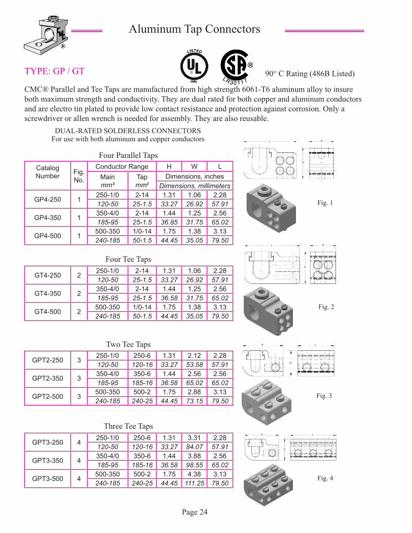
TYPE: GP / GT
CMC® Parallel and Tee Taps are manufactured from high strength 6061-T6 aluminum alloy to insure both maximum strength and conductivity. They are dual rated for both copper and aluminum conductors and are electro tin plated to provide low contact resistance and protection against corrosion. Only a screwdriver or allen wrench is needed for assembly. They are also reusable.
90° C Rating (486B Listed)
Aluminum Tap Connectors
Catalog Number Fig.
No.
Conductor Range H W LMainmm²
Tapmm²
Dimensions, inchesDimensions, millimeters
GP4-250 1250-1/0 2-14 1.31 1.06 2.28120-50 25-1.5 33.27 26.92 57.91
GP4-350 1350-4/0 2-14 1.44 1.25 2.56185-95 25-1.5 36.85 31.75 65.02
GP4-500 1500-350 1/0-14 1.75 1.38 3.13240-185 50-1.5 44.45 35.05 79.50
Page 24
Fig. 1
DUAL-RATED SOLDERLESS CONNECTORSFor use with both aluminum and copper conductors
GT4-250 2250-1/0 2-14 1.31 1.06 2.28120-50 25-1.5 33.27 26.92 57.91
GT4-350 2350-4/0 2-14 1.44 1.25 2.56185-95 25-1.5 36.58 31.75 65.02
GT4-500 2500-350 1/0-14 1.75 1.38 3.13240-185 50-1.5 44.45 35.05 79.50
GPT2-250 3250-1/0 250-6 1.31 2.12 2.28120-50 120-16 33.27 53.58 57.91
GPT2-350 3350-4/0 350-6 1.44 2.56 2.56185-95 185-16 36.58 65.02 65.02
GPT2-500 3500-350 500-2 1.75 2.88 3.13240-185 240-25 44.45 73.15 79.50
GPT3-250 4250-1/0 250-6 1.31 3.31 2.28120-50 120-16 33.27 84.07 57.91
GPT3-350 4350-4/0 350-6 1.44 3.88 2.56185-95 185-16 36.58 98.55 65.02
GPT3-500 4500-350 500-2 1.75 4.38 3.13240-185 240-25 44.45 111.25 79.50
Fig. 2
Fig. 3
Fig. 4
Four Parallel Taps
Four Tee Taps
Two Tee Taps
Three Tee Taps
WL
H
L W
H
W L
H
LW
H
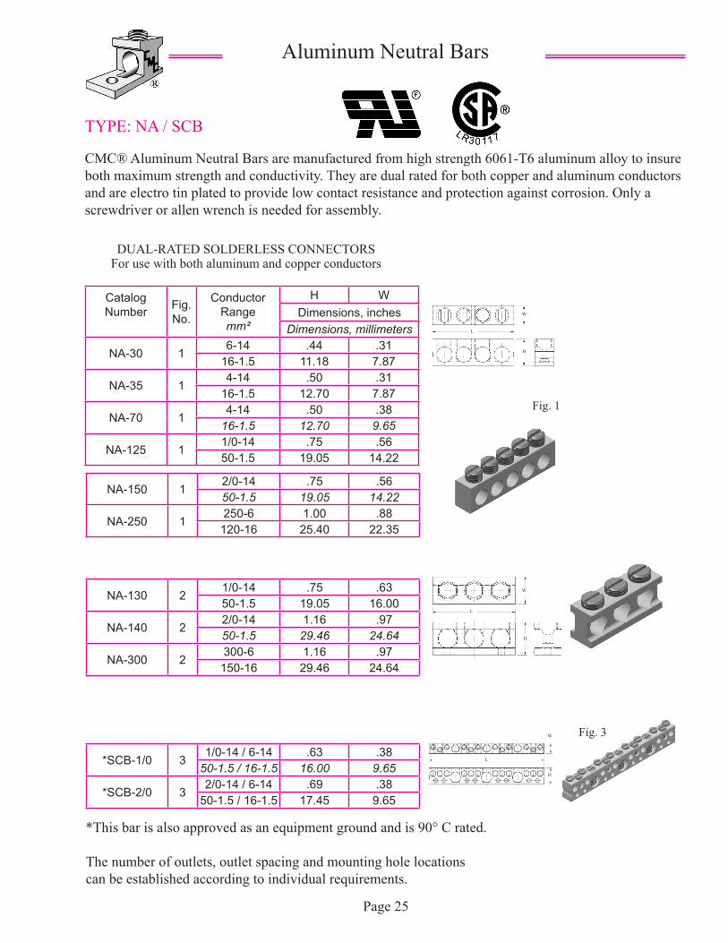
TYPE: NA / SCB
CMC® Aluminum Neutral Bars are manufactured from high strength 6061-T6 aluminum alloy to insure both maximum strength and conductivity. They are dual rated for both copper and aluminum conductors and are electro tin plated to provide low contact resistance and protection against corrosion. Only a screwdriver or allen wrench is needed for assembly.
Aluminum Neutral Bars
Catalog Number Fig.
No.
Conductor Rangemm²
H WDimensions, inches
Dimensions, millimeters
NA-30 16-14 .44 .31
16-1.5 11.18 7.87
NA-35 14-14 .50 .31
16-1.5 12.70 7.87
NA-70 14-14 .50 .38
16-1.5 12.70 9.65
NA-125 11/0-14 .75 .5650-1.5 19.05 14.22
Page 25
Fig. 1
DUAL-RATED SOLDERLESS CONNECTORSFor use with both aluminum and copper conductors
Fig. 2
NA-150 12/0-14 .75 .5650-1.5 19.05 14.22
NA-250 1250-6 1.00 .88
120-16 25.40 22.35
NA-130 21/0-14 .75 .6350-1.5 19.05 16.00
NA-140 22/0-14 1.16 .9750-1.5 29.46 24.64
NA-300 2300-6 1.16 .97
150-16 29.46 24.64
*SCB-1/0 31/0-14 / 6-14 .63 .38
50-1.5 / 16-1.5 16.00 9.65
*SCB-2/0 32/0-14 / 6-14 .69 .38
50-1.5 / 16-1.5 17.45 9.65
*This bar is also approved as an equipment ground and is 90° C rated.
The number of outlets, outlet spacing and mounting hole locations can be established according to individual requirements.
Fig. 3
W
L
H
W
L
H
W
L
H
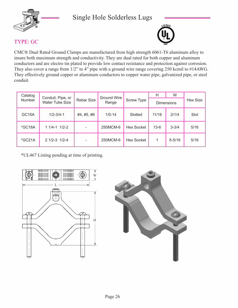
TYPE: GC
CMC® Dual Rated Ground Clamps are manufactured from high strength 6061-T6 aluminum alloy to insure both maximum strength and conductivity. They are dual rated for both copper and aluminum conductors and are electro tin plated to provide low contact resistance and protection against corrosion. They also cover a range from 1/2” to 4” pipe with a ground wire range covering 250 kcmil to #14AWG. They effectively ground copper or aluminum conductors to copper water pipe, galvanized pipe, or steel conduit.
Single Hole Solderless Lugs
Catalog Number Conduit, Pipe, or
Water Tube Size Rebar Size Ground Wire Range Screw Type
H WHex Size
Dimensions
GC15A 1/2-3/4-1 #4, #5, #6 1/0-14 Slotted 11/16 2/1/4 Slot
*GC18A 1 1/4-1 1/2-2 - 250MCM-6 Hex Socket 13-6 3-3/4 5/16
*GC21A 2 1/2-3 1/2-4 - 250MCM-6 Hex Socket 1 6-5/16 5/16
Page 26
*UL467 Listing pending at time of printing.
W
L
H
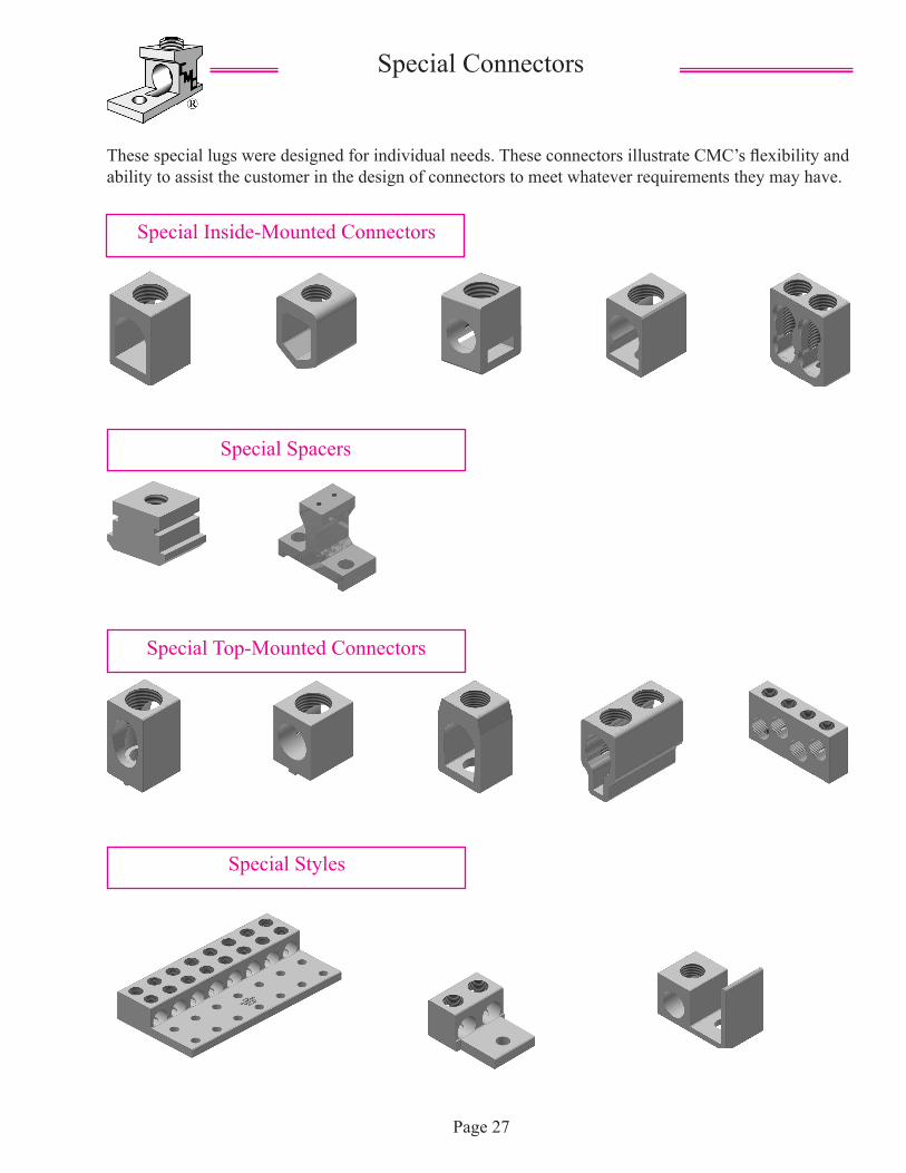
These special lugs were designed for individual needs. These connectors illustrate CMC’s flexibility and ability to assist the customer in the design of connectors to meet whatever requirements they may have.
Special Connectors
Page 27
Special Inside-Mounted Connectors
Special Spacers
Special Top-Mounted Connectors
Special Styles
Connector Manufacturing Company® fabricates the best in electrolytic copper electrical connectors. Copper connectors are formed from 100% pure electrolytic copper to eliminate the effects upon conductivity when alloys are utilized to reduce costs.
CMC® copper connectors are either extruded from pure electrolytic copper or formed from copper tubing carefully shaped to size. They may also be produced from copper strip which is used to form the tang or bus connection. These light weight connectors will perform better than many of the heavier, more bulky cast copper alloyed products on the market. This saves the customer the cost of metal, freight and space, while gaining top conductivity.
We therefore, offer these advantages in connector design:
Compact Design.High Strength - low heat rise copper.Relatively light weight construction.Economy and efficiency.Tested products in accordance with Underwriters Laboratories and the Canadian Standards Association requirements for listing.
These features together with our dedication for the highest quality standards available and an unsurpassed service level, provide our customers with maximum reliability.
CMC® Copper Connectors
Page 28
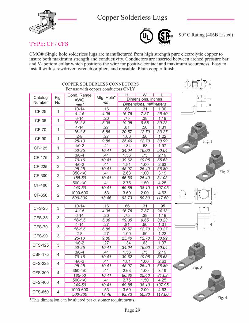
TYPE: CF / CFS
CMC® Single hole solderless lugs are manufactured from high strength pure electrolytic copper to insure both maximum strength and conductivity. Conductors are inserted between arched pressure bar and V- bottom collar which positions the wire for positive contact and maximum secureness. Easy to install with screwdriver, wrench or pliers and reusable. Plain copper finish.
90° C Rating (486B Listed)
Copper Solderless Lugs
Catalog Number
Fig. No.
Cond. RangeAWGmm²
Mtg. Hole*mm
H W LDimensions, inches
Dimensions, millimeters
CF-25 1 10-14 .16 .66 .31 1.004-1.5 4.06 16.76 7.87 25.40
CF-35 1 6-14 .20 .75 .38 1.1916-1.5 5.08 19.05 9.65 30.23
CF-70 1 4-14 .27 .81 .50 1.3116-1.5 6.86 20.57 12.70 33.27
CF-90 1 2-8 .27 1.00 .50 1.2225-10 9.86 25.40 12.70 30.99
CF-125 1 1/0-2 .41 1.34 .63 1.9750-25 10.41 34.04 16.00 50.04
CF-175 2 3/0-4 .41 1.56 .75 2.1970-16 10.41 39.62 19.05 55.63
CF-225 2 4/0-2 .41 1.81 1.00 2.6395-25 10.41 45.97 25.40 66.80
CF-300 2 350-1/0 .41 2.63 1.00 3.19185-50 10.41 66.80 25.40 81.03
CF-400 2 500-1/0 .41 2.75 1.50 4.25240-50 10.41 69.85 38.10 107.95
CF-650 2 1000-600 .53 3.69 2.00 4.63500-300 13.46 93.73 50.80 117.60
Page 29
CFS-25 3 10-14 .16 .66 .31 .954-1.5 4.06 16.76 7.87 24.13
CFS-35 3 6-14 .20 .75 .38 1.1916-1.5 5.08 19.05 9.65 30.23
CFS-70 3 4-14 .27 .81 .50 1.3116-1.5 6.86 20.57 12.70 33.27
CFS-90 3 2-8 .27 1.00 .50 1.2225-10 9.86 25.40 12.70 30.99
CFS-125 3 1/0-2 .27 1.34 .63 1.9750-25 10.41 34.04 16.00 50.04
CSF-175 4 3/0-4 .41 1.56 .75 2.1970-16 10.41 39.62 19.05 55.63
CFS-225 4 4/0-2 .41 1.81 1.00 2.6395-25 10.41 45.97 25.40 66.80
CFS-300 4 350-1/0 .41 2.63 1.00 3.19185-50 10.41 66.80 25.40 81.03
CFS-400 4 500-1/0 .41 2.75 1.50 4.25240-50 10.41 69.85 38.10 107.95
CFS-650 4 1000-600 .53 3.69 2.00 4.63500-300 13.46 93.73 50.80 117.60
Fig. 1
Fig. 2
Fig. 3
COPPER SOLDERLESS CONNECTORSFor use with copper conductors ONLY
Fig. 4*This dimension can be altered per customer requirements.
W
L
H
W
L
H
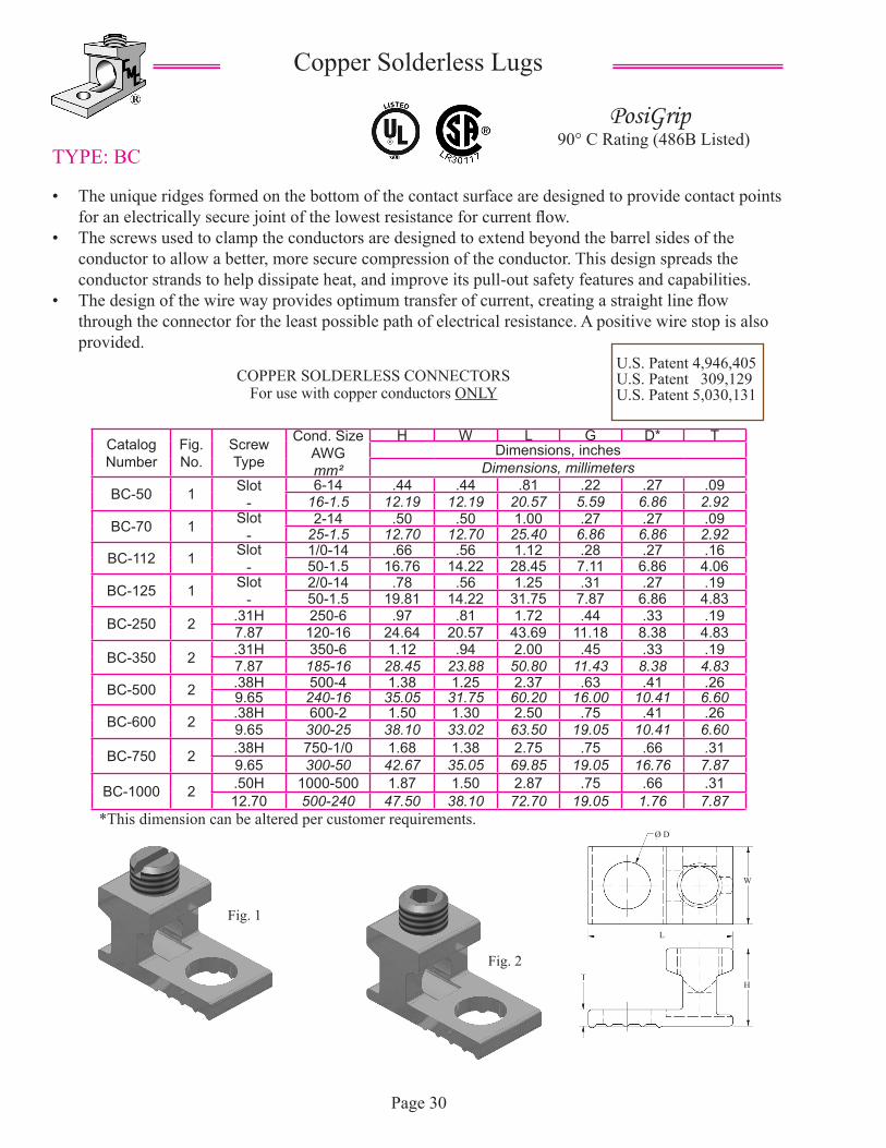
TYPE: BC
• The unique ridges formed on the bottom of the contact surface are designed to provide contact points for an electrically secure joint of the lowest resistance for current flow.
• The screws used to clamp the conductors are designed to extend beyond the barrel sides of the conductor to allow a better, more secure compression of the conductor. This design spreads the conductor strands to help dissipate heat, and improve its pull-out safety features and capabilities.
• The design of the wire way provides optimum transfer of current, creating a straight line flow through the connector for the least possible path of electrical resistance. A positive wire stop is also provided.
Copper Solderless Lugs
Catalog Number
Fig. No.
Screw Type
Cond. SizeAWGmm²
H W L G D* TDimensions, inches
Dimensions, millimeters
BC-50 1 Slot-
6-14 .44 .44 .81 .22 .27 .0916-1.5 12.19 12.19 20.57 5.59 6.86 2.92
BC-70 1 Slot-
2-14 .50 .50 1.00 .27 .27 .0925-1.5 12.70 12.70 25.40 6.86 6.86 2.92
BC-112 1 Slot-
1/0-14 .66 .56 1.12 .28 .27 .1650-1.5 16.76 14.22 28.45 7.11 6.86 4.06
BC-125 1 Slot-
2/0-14 .78 .56 1.25 .31 .27 .1950-1.5 19.81 14.22 31.75 7.87 6.86 4.83
BC-250 2 .31H 250-6 .97 .81 1.72 .44 .33 .197.87 120-16 24.64 20.57 43.69 11.18 8.38 4.83
BC-350 2 .31H 350-6 1.12 .94 2.00 .45 .33 .197.87 185-16 28.45 23.88 50.80 11.43 8.38 4.83
BC-500 2 .38H 500-4 1.38 1.25 2.37 .63 .41 .269.65 240-16 35.05 31.75 60.20 16.00 10.41 6.60
BC-600 2 .38H 600-2 1.50 1.30 2.50 .75 .41 .269.65 300-25 38.10 33.02 63.50 19.05 10.41 6.60
BC-750 2 .38H 750-1/0 1.68 1.38 2.75 .75 .66 .319.65 300-50 42.67 35.05 69.85 19.05 16.76 7.87
BC-1000 2 .50H 1000-500 1.87 1.50 2.87 .75 .66 .3112.70 500-240 47.50 38.10 72.70 19.05 1.76 7.87
Page 30
U.S. Patent 4,946,405U.S. Patent 309,129U.S. Patent 5,030,131
90° C Rating (486B Listed)PosiGrip
*This dimension can be altered per customer requirements.
Fig. 1
Fig. 2
COPPER SOLDERLESS CONNECTORSFor use with copper conductors ONLY
W
L
H
Ø D
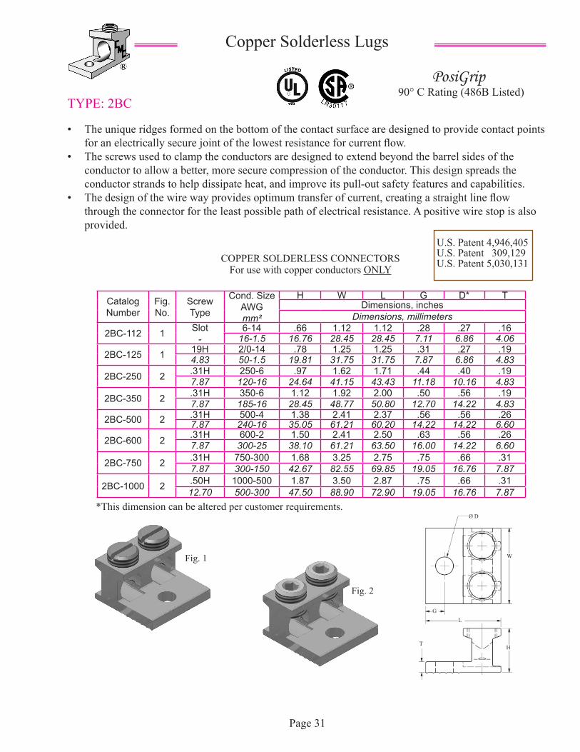
TYPE: 2BC
• The unique ridges formed on the bottom of the contact surface are designed to provide contact points for an electrically secure joint of the lowest resistance for current flow.
• The screws used to clamp the conductors are designed to extend beyond the barrel sides of the conductor to allow a better, more secure compression of the conductor. This design spreads the conductor strands to help dissipate heat, and improve its pull-out safety features and capabilities.
• The design of the wire way provides optimum transfer of current, creating a straight line flow through the connector for the least possible path of electrical resistance. A positive wire stop is also provided.
Copper Solderless Lugs
Catalog Number
Fig. No.
Screw Type
Cond. SizeAWGmm²
H W L G D* TDimensions, inches
Dimensions, millimeters
2BC-112 1 Slot-
6-14 .66 1.12 1.12 .28 .27 .1616-1.5 16.76 28.45 28.45 7.11 6.86 4.06
2BC-125 1 19H 2/0-14 .78 1.25 1.25 .31 .27 .194.83 50-1.5 19.81 31.75 31.75 7.87 6.86 4.83
2BC-250 2 .31H 250-6 .97 1.62 1.71 .44 .40 .197.87 120-16 24.64 41.15 43.43 11.18 10.16 4.83
2BC-350 2 .31H 350-6 1.12 1.92 2.00 .50 .56 .197.87 185-16 28.45 48.77 50.80 12.70 14.22 4.83
2BC-500 2 .31H 500-4 1.38 2.41 2.37 .56 .56 .267.87 240-16 35.05 61.21 60.20 14.22 14.22 6.60
2BC-600 2 .31H 600-2 1.50 2.41 2.50 .63 .56 .267.87 300-25 38.10 61.21 63.50 16.00 14.22 6.60
2BC-750 2 .31H 750-300 1.68 3.25 2.75 .75 .66 .317.87 300-150 42.67 82.55 69.85 19.05 16.76 7.87
2BC-1000 2 .50H 1000-500 1.87 3.50 2.87 .75 .66 .3112.70 500-300 47.50 88.90 72.90 19.05 16.76 7.87
Page 31
U.S. Patent 4,946,405U.S. Patent 309,129U.S. Patent 5,030,131
90° C Rating (486B Listed)PosiGrip
*This dimension can be altered per customer requirements.
Fig. 1
Fig. 2
COPPER SOLDERLESS CONNECTORSFor use with copper conductors ONLY
W
H
L
T
G
Ø D
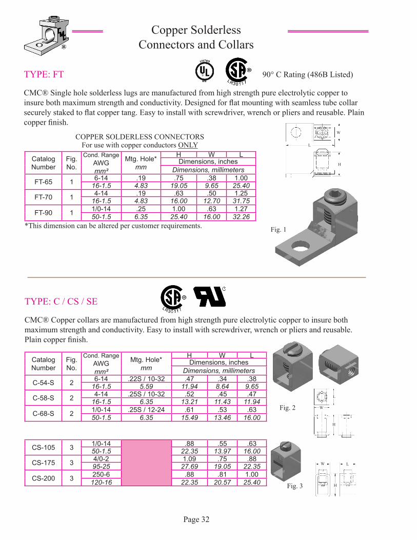
TYPE: FT
CMC® Single hole solderless lugs are manufactured from high strength pure electrolytic copper to insure both maximum strength and conductivity. Designed for flat mounting with seamless tube collar securely staked to flat copper tang. Easy to install with screwdriver, wrench or pliers and reusable. Plain copper finish.
Copper Solderless Connectors and Collars
Catalog Number
Fig. No.
Cond. RangeAWGmm²
Mtg. Hole*mm
H W LDimensions, inches
Dimensions, millimeters
FT-65 1 6-14 .19 .75 .38 1.0016-1.5 4.83 19.05 9.65 25.40
FT-70 1 4-14 .19 .63 .50 1.2516-1.5 4.83 16.00 12.70 31.75
FT-90 1 1/0-14 .25 1.00 .63 1.2750-1.5 6.35 25.40 16.00 32.26
Page 32
COPPER SOLDERLESS CONNECTORSFor use with copper conductors ONLY
90° C Rating (486B Listed)
*This dimension can be altered per customer requirements. Fig. 1
Fig. 2
TYPE: C / CS / SE
CMC® Copper collars are manufactured from high strength pure electrolytic copper to insure both maximum strength and conductivity. Easy to install with screwdriver, wrench or pliers and reusable. Plain copper finish.
Catalog Number
Fig. No.
Cond. RangeAWGmm²
Mtg. Hole*mm
H W LDimensions, inches
Dimensions, millimeters
C-54-S 2 6-14 .22S / 10-32 .47 .34 .3816-1.5 5.59 11.94 8.64 9.65
C-58-S 2 4-14 .25S / 10-32 .52 .45 .4716-1.5 6.35 13.21 11.43 11.94
C-68-S 2 1/0-14 .25S / 12-24 .61 .53 .6350-1.5 6.35 15.49 13.46 16.00
CS-105 3 1/0-14 .88 .55 .6350-1.5 22.35 13.97 16.00
CS-175 3 4/0-2 1.09 .75 .8895-25 27.69 19.05 22.35
CS-200 3 250-6 .88 .81 1.00120-16 22.35 20.57 25.40 Fig. 3
W
L
H
W
W
H
H
L
L
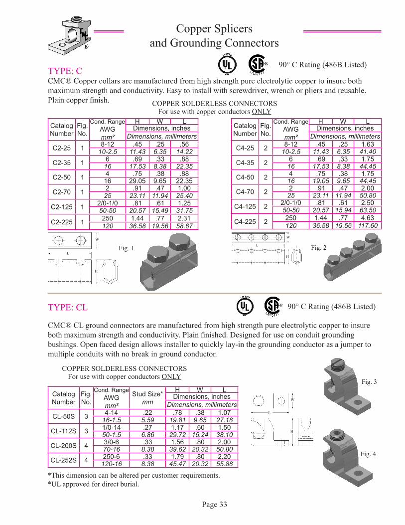
TYPE: CCMC® Copper collars are manufactured from high strength pure electrolytic copper to insure both maximum strength and conductivity. Easy to install with screwdriver, wrench or pliers and reusable. Plain copper finish.
Copper Splicers and Grounding Connectors
Catalog Number
Fig. No.
Cond. RangeAWGmm²
H W LDimensions, inches
Dimensions, millimeters
C2-25 1 8-12 .45 .25 .5610-2.5 11.43 6.35 14.22
C2-35 1 6 .69 .33 .8816 17.53 8.38 22.35
C2-50 1 4 .75 .38 .8816 29.05 9.65 22.35
C2-70 1 2 .91 .47 1.0025 23.11 11.94 25.40
C2-125 1 2/0-1/0 .81 .61 1.2550-50 20.57 15.49 31.75
C2-225 1 250 1.44 .77 2.31120 36.58 19.56 58.67
Page 33
COPPER SOLDERLESS CONNECTORSFor use with copper conductors ONLY
90° C Rating (486B Listed)
Catalog Number
Fig. No.
Cond. RangeAWGmm²
H W LDimensions, inches
Dimensions, millimeters
C4-25 2 8-12 .45 .25 1.6310-2.5 11.43 6.35 41.40
C4-35 2 6 .69 .33 1.7516 17.53 8.38 44.45
C4-50 2 4 .75 .38 1.7516 19.05 9.65 44.45
C4-70 2 2 .91 .47 2.0025 23.11 11.94 50.80
C4-125 2 2/0-1/0 .81 .61 2.5050-50 20.57 15.94 63.50
C4-225 2 250 1.44 .77 4.63120 36.58 19.56 117.60
Fig. 1 Fig. 2
90° C Rating (486B Listed)TYPE: CL
CMC® CL ground connectors are manufactured from high strength pure electrolytic copper to insure both maximum strength and conductivity. Plain finished. Designed for use on conduit grounding bushings. Open faced design allows installer to quickly lay-in the grounding conductor as a jumper to multiple conduits with no break in ground conductor.
COPPER SOLDERLESS CONNECTORSFor use with copper conductors ONLY
*This dimension can be altered per customer requirements.*UL approved for direct burial.
Catalog Number
Fig. No.
Cond. RangeAWGmm²
Stud Size*mm
H W LDimensions, inches
Dimensions, millimeters
CL-50S 3 4-14 .22 .78 .38 1.0716-1.5 5.59 19.81 9.65 27.18
CL-112S 3 1/0-14 .27 1.17 .60 1.5050-1.5 6.86 29.72 15.24 38.10
CL-200S 4 3/0-6 .33 1.56 .80 2.0070-16 8.38 39.62 20.32 50.80
CL-252S 4 250-6 .33 1.79 .80 2.20120-16 8.38 45.47 20.32 55.88
Fig. 4
Fig. 3
W
H
L
W
H
LW
H
L
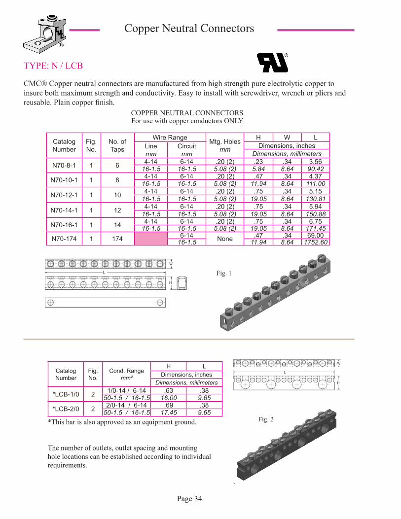
TYPE: N / LCB
CMC® Copper neutral connectors are manufactured from high strength pure electrolytic copper to insure both maximum strength and conductivity. Easy to install with screwdriver, wrench or pliers and reusable. Plain copper finish.
Copper Neutral Connectors
Catalog Number
Fig. No.
No. of Taps
Wire Range Mtg. Holes mm
H W LLinemm
Circuitmm
Dimensions, inchesDimensions, millimeters
N70-8-1 1 6 4-14 6-14 .20 (2) .23 .34 3.5616-1.5 16-1.5 5.08 (2) 5.84 8.64 90.42
N70-10-1 1 8 4-14 6-14 .20 (2) .47 .34 4.3716-1.5 16-1.5 5.08 (2) 11.94 8.64 111.00
N70-12-1 1 10 4-14 6-14 .20 (2) .75 .34 5.1516-1.5 16-1.5 5.08 (2) 19.05 8.64 130.81
N70-14-1 1 12 4-14 6-14 .20 (2) .75 .34 5.9416-1.5 16-1.5 5.08 (2) 19.05 8.64 150.88
N70-16-1 1 14 4-14 6-14 .20 (2) .75 .34 6.7516-1.5 16-1.5 5.08 (2) 19.05 8.64 171.45
N70-174 1 174 6-14 None .47 .34 69.0016-1.5 11.94 8.64 1752.60
Page 34
*This bar is also approved as an equipment ground.
The number of outlets, outlet spacing and mounting hole locations can be established according to individual requirements.
COPPER NEUTRAL CONNECTORSFor use with copper conductors ONLY
Fig. 1
Catalog Number
Fig. No.
Cond. Rangemm²
H LDimensions, inches
Dimensions, millimeters
*LCB-1/0 2 1/0-14 / 6-14 .63 .3850-1.5 / 16-1.5 16.00 9.65
*LCB-2/0 2 2/0-14 / 6-14 .69 .3850-1.5 / 16-1.5 17.45 9.65
Fig. 2
W
H
L
W
H
L
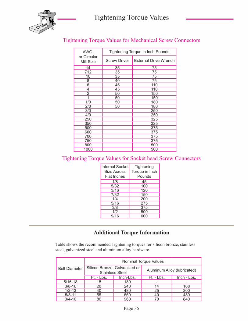
Tightening Torque Values for Mechanical Screw Connectors
Tightening Torque Values
AWG. or Circular Mill Size
Tightening Torque in Inch Pounds
Screw Driver External Drive Wrench
14 35 75712 35 7510 35 758 40 756 45 1104 45 1102 50 1501 50 150
1/0 50 1802/0 50 1803/0 2504/0 250250 325350 325500 375600 375700 375750 375800 500
1000 500
Page 35
Table shows the recommended Tightening torques for silicon bronze, stainless steel, galvanized steel and aluminum alloy hardware.
Internal Socket Size Across Flat Inches
Tightening Torque in Inch
Pounds1/8 45
5/32 1003/16 1207/32 1501/4 200
5/16 2753/8 3751/2 500
9/16 600
Tightening Torque Values for Socket head Screw Connectors
Additional Torque Information
Bolt Diameter
Nominal Torque ValuesSilicon Bronze, Galvanized or
Stainless Steel Aluminum Alloy (lubricated)
Ft. - Lbs. Inch-Lbs. Ft. - Lbs. Inch - Lbs.5/16-18 15 180 - -3/8-16 20 240 14 1681/2-13 40 480 25 3005/8-11 55 660 40 4803/4-10 80 960 70 840
Additional Torque Information
Page 36
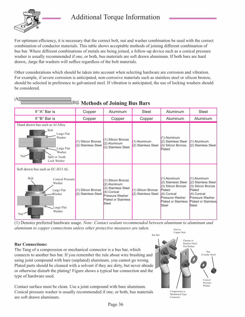
For optimum efficiency, it is necessary that the correct bolt, nut and washer combination be used with the correct combination of conductor materials. This table shows acceptable methods of joining different combination of bus bar. Where different combinations of metals are being joined, a follow-up device such as a conical pressure washer is usually recommended if one, or both, bus materials are soft drawn aluminum. If both bars are hard drawn, ;large flat washers will suffice regardless of the bolt materials.
Other considerations which should be taken into account when selecting hardware are corrosion and vibration. For example, if severe corrosion is anticipated, non-corrosive materials such as stainless steel or silicon bronze, should be selected in preference to galvanized steel. If vibration is anticipated, the use of locking washers should be considered.
Methods of Joining Bus Bars
Bar Connections:The Tang of a compression or mechanical connector is a bus bar, which connects to another bus bar. If you remember the rule about wire brushing and using joint compound with bare (unplated) aluminum, you cannot go wrong. Plated parts should be cleaned with a solvent if they are dirty, but never abrade or otherwise disturb the plating! Figure shows a typical bar connection and the type of hardware used.
Contact surface must be clean. Use a joint compound with bare aluminum. Conical pressure washer is usually recommended if one, or both, bus materials are soft drawn aluminum.
(1) Denotes preferred hardware usage. Note: Contact sealant recommended between aluminum to aluminum and aluminum to copper connections unless other protective measures are taken.
If “A” Bar is Copper Aluminum Steel Aluminum Steel
If “B” Bar is Copper Copper Copper Aluminum Aluminum
(1) Silicon Bronze(2) Stainless Steel
(1) Silicon Bronze(2) Aluminum(3) Stainless Steel
(1) Aluminum(2) Stainless Steel
(1) Aluminum(2) Stainless Steel(3) Silicon Bronze, Plated
(1) Aluminum(2) Stainless Steel
(1) Silicon Bronze(2) Stainless Steel
(1) Silicon Bronze(2) Aluminum(3) Stainless Steel(4) Conical Pressure Washer Plated or Stainless Steel
(1) Silicon Bronze(2) Stainless Steel
(1) Aluminum(2) Stainless Steel(3) Silicon Bronze Plated(4) Conical Pressure Washer Plated or Stainless Steel
(1) Aluminum(2) Stainless Steel(3) Silicon Bronze Plated(4) Conical Pressure Washer Plated or Stainless Steel
Hand drawn bus such as Al AlloyBolt
Large Flat Washer
Large Flat Washer
Split or Tooth Lock Washer
Nut
Large Flat Washer
Large Flat Washer
Conical Pressure Washer
Bolt
Nut
Soft drawn bus such as EC-H13 AL
AB
Bus Bar
Steel or Copper Stud
Nut (Usually Steel)
Conical Pressure Washer
Chrome or Stainless Steel Flat Washer
Compression or Mechanical Type Connector
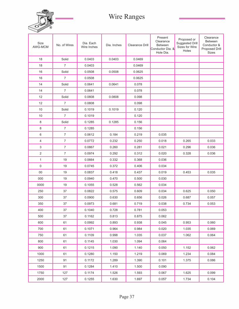
Wire Ranges
Size AWG-MCM No. of Wires Dia. Each
Wire Inches Dia. Inches Clearance Drill
Present Clearance Between
Conductor Dia. & Hole Dia.
Proposed or Suggested Drill Sizes for Wire
Holes
Clearance Between
Conductor & Proposed Drill
Sizes
18 Solid 0.0403 0.0403 0.0469
18 7 0.0403 0.0469
16 Solid 0.0508 0.0508 0.0625
16 7 0.0508 0.0625
14 Solid 0.0641 0.0641 0.078
14 7 0.0641 0.078
12 Solid 0.0808 0.0808 0.098
12 7 0.0808 0.098
10 Solid 0.1019 0.1019 0.120
10 7 0.1019 0.120
8 Solid 0.1285 0.1285 0.156
8 7 0.1285 0.156
6 7 0.0612 0.184 0.219 0.035
4 7 0.0772 0.232 0.250 0.018 0.265 0.033
3 7 0.0867 0.260 0.281 0.021 0.296 0.036
2 7 0.0974 0.292 0.312 0.020 0.328 0.036
1 19 0.0664 0.332 0.368 0.036
0 19 0.0745 0.372 0.406 0.034
00 19 0.0837 0.418 0.437 0.019 0.453 0.035
000 19 0.0940 0.470 0.500 0.030
0000 19 0.1055 0.528 0.562 0.034
250 37 0.0822 0.575 0.609 0.034 0.625 0.050
300 37 0.0900 0.630 0.656 0.026 0.687 0.057
350 37 0.0973 0.681 0.719 0.038 0.734 0.053
400 37 0.1040 0.728 0.781 0.053
500 37 0.1162 0.813 0.875 0.062
600 61 0.0992 0.893 0.938 0.045 0.953 0.060
700 61 0.1071 0.964 0.984 0.020 1.035 0.069
750 61 0.1109 0.998 1.035 0.037 1.062 0.064
800 61 0.1145 1.030 1.094 0.064
900 61 0.1215 1.090 1.140 0.050 1.152 0.062
1000 61 0.1280 1.150 1.219 0.069 1.234 0.084
1250 91 0.1172 1.289 1.390 0.101 1.375 0.086
1500 91 0.1284 1.410 1.500 0.090
1750 127 0.1174 1.526 1.593 0.067 1.625 0.099
2000 127 0.1255 1.630 1.697 0.057 1.734 0.104
Page 37
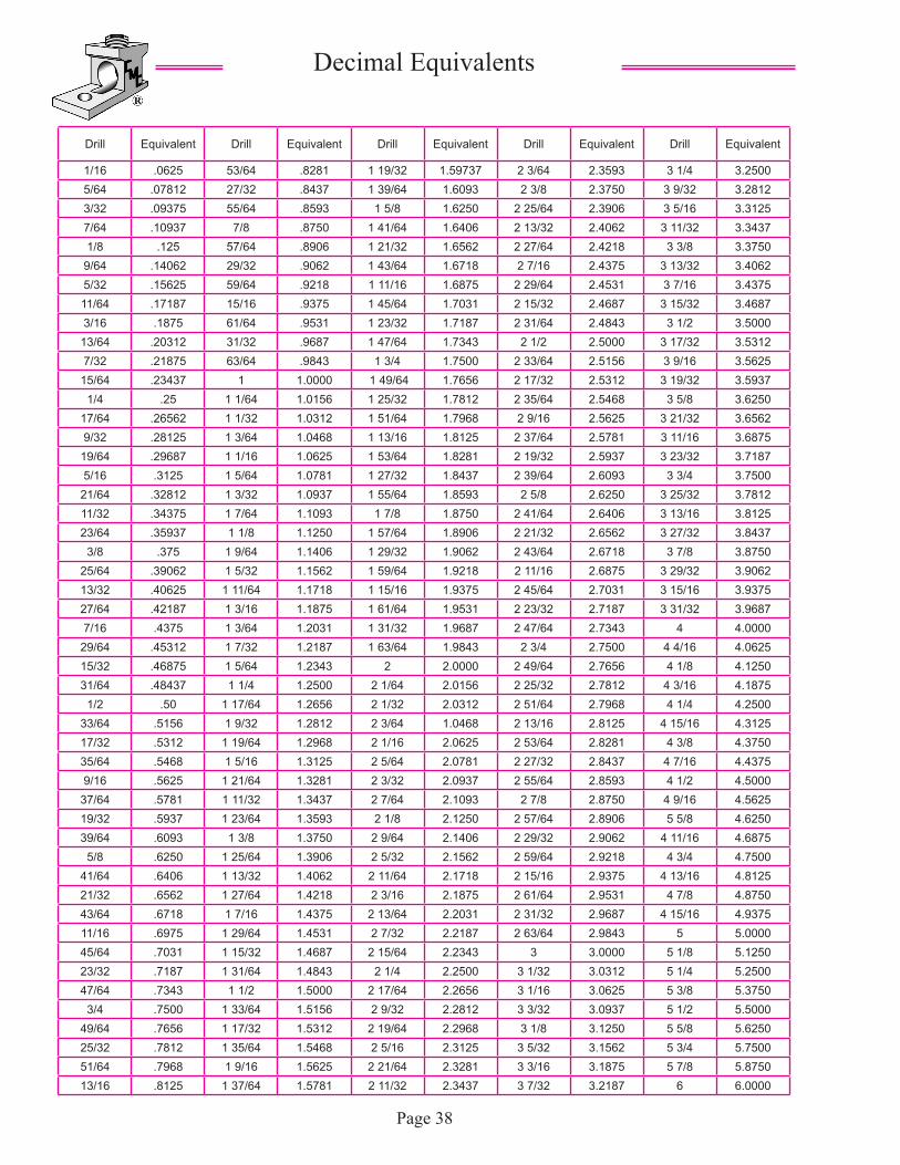
Decimal Equivalents
Drill Equivalent Drill Equivalent Drill Equivalent Drill Equivalent Drill Equivalent
1/16 .0625 53/64 .8281 1 19/32 1.59737 2 3/64 2.3593 3 1/4 3.25005/64 .07812 27/32 .8437 1 39/64 1.6093 2 3/8 2.3750 3 9/32 3.28123/32 .09375 55/64 .8593 1 5/8 1.6250 2 25/64 2.3906 3 5/16 3.31257/64 .10937 7/8 .8750 1 41/64 1.6406 2 13/32 2.4062 3 11/32 3.34371/8 .125 57/64 .8906 1 21/32 1.6562 2 27/64 2.4218 3 3/8 3.3750
9/64 .14062 29/32 .9062 1 43/64 1.6718 2 7/16 2.4375 3 13/32 3.40625/32 .15625 59/64 .9218 1 11/16 1.6875 2 29/64 2.4531 3 7/16 3.437511/64 .17187 15/16 .9375 1 45/64 1.7031 2 15/32 2.4687 3 15/32 3.46873/16 .1875 61/64 .9531 1 23/32 1.7187 2 31/64 2.4843 3 1/2 3.5000
13/64 .20312 31/32 .9687 1 47/64 1.7343 2 1/2 2.5000 3 17/32 3.53127/32 .21875 63/64 .9843 1 3/4 1.7500 2 33/64 2.5156 3 9/16 3.5625
15/64 .23437 1 1.0000 1 49/64 1.7656 2 17/32 2.5312 3 19/32 3.59371/4 .25 1 1/64 1.0156 1 25/32 1.7812 2 35/64 2.5468 3 5/8 3.6250
17/64 .26562 1 1/32 1.0312 1 51/64 1.7968 2 9/16 2.5625 3 21/32 3.65629/32 .28125 1 3/64 1.0468 1 13/16 1.8125 2 37/64 2.5781 3 11/16 3.6875
19/64 .29687 1 1/16 1.0625 1 53/64 1.8281 2 19/32 2.5937 3 23/32 3.71875/16 .3125 1 5/64 1.0781 1 27/32 1.8437 2 39/64 2.6093 3 3/4 3.7500
21/64 .32812 1 3/32 1.0937 1 55/64 1.8593 2 5/8 2.6250 3 25/32 3.781211/32 .34375 1 7/64 1.1093 1 7/8 1.8750 2 41/64 2.6406 3 13/16 3.812523/64 .35937 1 1/8 1.1250 1 57/64 1.8906 2 21/32 2.6562 3 27/32 3.8437
3/8 .375 1 9/64 1.1406 1 29/32 1.9062 2 43/64 2.6718 3 7/8 3.875025/64 .39062 1 5/32 1.1562 1 59/64 1.9218 2 11/16 2.6875 3 29/32 3.906213/32 .40625 1 11/64 1.1718 1 15/16 1.9375 2 45/64 2.7031 3 15/16 3.937527/64 .42187 1 3/16 1.1875 1 61/64 1.9531 2 23/32 2.7187 3 31/32 3.96877/16 .4375 1 3/64 1.2031 1 31/32 1.9687 2 47/64 2.7343 4 4.0000
29/64 .45312 1 7/32 1.2187 1 63/64 1.9843 2 3/4 2.7500 4 4/16 4.062515/32 .46875 1 5/64 1.2343 2 2.0000 2 49/64 2.7656 4 1/8 4.125031/64 .48437 1 1/4 1.2500 2 1/64 2.0156 2 25/32 2.7812 4 3/16 4.1875
1/2 .50 1 17/64 1.2656 2 1/32 2.0312 2 51/64 2.7968 4 1/4 4.250033/64 .5156 1 9/32 1.2812 2 3/64 1.0468 2 13/16 2.8125 4 15/16 4.312517/32 .5312 1 19/64 1.2968 2 1/16 2.0625 2 53/64 2.8281 4 3/8 4.375035/64 .5468 1 5/16 1.3125 2 5/64 2.0781 2 27/32 2.8437 4 7/16 4.43759/16 .5625 1 21/64 1.3281 2 3/32 2.0937 2 55/64 2.8593 4 1/2 4.5000
37/64 .5781 1 11/32 1.3437 2 7/64 2.1093 2 7/8 2.8750 4 9/16 4.562519/32 .5937 1 23/64 1.3593 2 1/8 2.1250 2 57/64 2.8906 5 5/8 4.625039/64 .6093 1 3/8 1.3750 2 9/64 2.1406 2 29/32 2.9062 4 11/16 4.6875
5/8 .6250 1 25/64 1.3906 2 5/32 2.1562 2 59/64 2.9218 4 3/4 4.750041/64 .6406 1 13/32 1.4062 2 11/64 2.1718 2 15/16 2.9375 4 13/16 4.812521/32 .6562 1 27/64 1.4218 2 3/16 2.1875 2 61/64 2.9531 4 7/8 4.875043/64 .6718 1 7/16 1.4375 2 13/64 2.2031 2 31/32 2.9687 4 15/16 4.937511/16 .6975 1 29/64 1.4531 2 7/32 2.2187 2 63/64 2.9843 5 5.000045/64 .7031 1 15/32 1.4687 2 15/64 2.2343 3 3.0000 5 1/8 5.125023/32 .7187 1 31/64 1.4843 2 1/4 2.2500 3 1/32 3.0312 5 1/4 5.250047/64 .7343 1 1/2 1.5000 2 17/64 2.2656 3 1/16 3.0625 5 3/8 5.3750
3/4 .7500 1 33/64 1.5156 2 9/32 2.2812 3 3/32 3.0937 5 1/2 5.500049/64 .7656 1 17/32 1.5312 2 19/64 2.2968 3 1/8 3.1250 5 5/8 5.625025/32 .7812 1 35/64 1.5468 2 5/16 2.3125 3 5/32 3.1562 5 3/4 5.750051/64 .7968 1 9/16 1.5625 2 21/64 2.3281 3 3/16 3.1875 5 7/8 5.875013/16 .8125 1 37/64 1.5781 2 11/32 2.3437 3 7/32 3.2187 6 6.0000
Page 38