Embed Size (px)
Citation preview
Generalized-Mapping IPC for L4
Andreas Weigand
Technischen Universität DresdenDepartment of Computer Science
Operating Systems Group
April 2004

2
Contents
1 Introduction 91.1 Organization of this Document. . . . . . . . . . . . . . . . . . . . . . . . . . . . . . . . 91.2 Acknowledgements. . . . . . . . . . . . . . . . . . . . . . . . . . . . . . . . . . . . . . 9
2 Background and Related Work 112.1 Microkernels . . . . . . . . . . . . . . . . . . . . . . . . . . . . . . . . . . . . . . . . .112.2 Access Control . . . . . . . . . . . . . . . . . . . . . . . . . . . . . . . . . . . . . . . .12
2.2.1 Access Matrix . . . . . . . . . . . . . . . . . . . . . . . . . . . . . . . . . . . . 122.2.2 Access Control Lists. . . . . . . . . . . . . . . . . . . . . . . . . . . . . . . . . 122.2.3 Capabilities. . . . . . . . . . . . . . . . . . . . . . . . . . . . . . . . . . . . . . 13
2.3 The L4 Memory Model. . . . . . . . . . . . . . . . . . . . . . . . . . . . . . . . . . . . 142.3.1 Recursive Virtual Address Space Construction. . . . . . . . . . . . . . . . . . . 152.3.2 Mapping Database. . . . . . . . . . . . . . . . . . . . . . . . . . . . . . . . . . 162.3.3 Page Fault Handling. . . . . . . . . . . . . . . . . . . . . . . . . . . . . . . . . 17
3 Design 193.1 Requirements. . . . . . . . . . . . . . . . . . . . . . . . . . . . . . . . . . . . . . . . .203.2 Generalized Mappings for IPC Management. . . . . . . . . . . . . . . . . . . . . . . . . 20
3.2.1 Distribution of Send Capabilities. . . . . . . . . . . . . . . . . . . . . . . . . . . 213.2.2 Preventing the Unwanted Distribution of Rights. . . . . . . . . . . . . . . . . . . 223.2.3 Capability Fault Handling. . . . . . . . . . . . . . . . . . . . . . . . . . . . . . 243.2.4 Local Id’s on the Sender Side. . . . . . . . . . . . . . . . . . . . . . . . . . . . 253.2.5 Local Id’s on the Receiver Side. . . . . . . . . . . . . . . . . . . . . . . . . . . 253.2.6 Receiver Selection. . . . . . . . . . . . . . . . . . . . . . . . . . . . . . . . . . 273.2.7 Starting a System. . . . . . . . . . . . . . . . . . . . . . . . . . . . . . . . . . . 28
3.3 Scenarios . . . . . . . . . . . . . . . . . . . . . . . . . . . . . . . . . . . . . . . . . . .293.3.1 A Message Interceptor. . . . . . . . . . . . . . . . . . . . . . . . . . . . . . . . 293.3.2 Global Id’s . . . . . . . . . . . . . . . . . . . . . . . . . . . . . . . . . . . . . . 31
3.4 The Prototype. . . . . . . . . . . . . . . . . . . . . . . . . . . . . . . . . . . . . . . . .333.4.1 General Architecture. . . . . . . . . . . . . . . . . . . . . . . . . . . . . . . . . 33
4 Implementation 354.1 Library Architecture . . . . . . . . . . . . . . . . . . . . . . . . . . . . . . . . . . . . . 354.2 IPC Implementation in Detail. . . . . . . . . . . . . . . . . . . . . . . . . . . . . . . . . 36
4.2.1 Receiver Preparation. . . . . . . . . . . . . . . . . . . . . . . . . . . . . . . . . 364.2.2 Send Operation in Detail. . . . . . . . . . . . . . . . . . . . . . . . . . . . . . . 374.2.3 Implementing an Atomic Call. . . . . . . . . . . . . . . . . . . . . . . . . . . . 384.2.4 Implementing Timeouts for IPC. . . . . . . . . . . . . . . . . . . . . . . . . . . 394.2.5 Capability Mapping and Unmapping. . . . . . . . . . . . . . . . . . . . . . . . . 404.2.6 Capability Fault Handling. . . . . . . . . . . . . . . . . . . . . . . . . . . . . . 40
4.3 Matching Requirements. . . . . . . . . . . . . . . . . . . . . . . . . . . . . . . . . . . . 414.4 Receiver Selection Algorithms. . . . . . . . . . . . . . . . . . . . . . . . . . . . . . . . 41
3
4 CONTENTS
4.4.1 Linear List Search. . . . . . . . . . . . . . . . . . . . . . . . . . . . . . . . . . 414.4.2 Binary Trees and Tries. . . . . . . . . . . . . . . . . . . . . . . . . . . . . . . . 424.4.3 Page Table like Structures. . . . . . . . . . . . . . . . . . . . . . . . . . . . . . 444.4.4 Hashing. . . . . . . . . . . . . . . . . . . . . . . . . . . . . . . . . . . . . . . .46
5 Evaluation 495.1 Performance on the Sender Side. . . . . . . . . . . . . . . . . . . . . . . . . . . . . . . 505.2 Performance on the Receiver Side. . . . . . . . . . . . . . . . . . . . . . . . . . . . . . 51
6 Conclusion 536.1 Future Work. . . . . . . . . . . . . . . . . . . . . . . . . . . . . . . . . . . . . . . . . .54
A Appendix 55A.1 Glossary. . . . . . . . . . . . . . . . . . . . . . . . . . . . . . . . . . . . . . . . . . . .55A.2 Acronyms . . . . . . . . . . . . . . . . . . . . . . . . . . . . . . . . . . . . . . . . . . .56
List of Figures
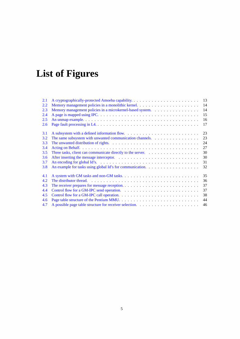
2.1 A cryptographically-protected Amoeba capability.. . . . . . . . . . . . . . . . . . . . . . 132.2 Memory management policies in a monolithic kernel.. . . . . . . . . . . . . . . . . . . . 142.3 Memory management policies in a microkernel-based system.. . . . . . . . . . . . . . . 142.4 A page is mapped using IPC.. . . . . . . . . . . . . . . . . . . . . . . . . . . . . . . . . 152.5 An unmap example.. . . . . . . . . . . . . . . . . . . . . . . . . . . . . . . . . . . . . . 162.6 Page fault processing in L4.. . . . . . . . . . . . . . . . . . . . . . . . . . . . . . . . . . 17
3.1 A subsystem with a defined information flow.. . . . . . . . . . . . . . . . . . . . . . . . 233.2 The same subsystem with unwanted communication channels.. . . . . . . . . . . . . . . 233.3 The unwanted distribution of rights.. . . . . . . . . . . . . . . . . . . . . . . . . . . . . 243.4 Acting on Behalf.. . . . . . . . . . . . . . . . . . . . . . . . . . . . . . . . . . . . . . .273.5 Three tasks, client can communicate directly to the server.. . . . . . . . . . . . . . . . . 303.6 After inserting the message interceptor.. . . . . . . . . . . . . . . . . . . . . . . . . . . 303.7 An encoding for global Id’s. . . . . . . . . . . . . . . . . . . . . . . . . . . . . . . . . . 313.8 An example for tasks using global Id’s for communication.. . . . . . . . . . . . . . . . . 32
4.1 A system with GM tasks and non-GM tasks.. . . . . . . . . . . . . . . . . . . . . . . . . 354.2 The distributor thread.. . . . . . . . . . . . . . . . . . . . . . . . . . . . . . . . . . . . 364.3 The receiver prepares for message reception.. . . . . . . . . . . . . . . . . . . . . . . . . 374.4 Control flow for a GM-IPC send operation.. . . . . . . . . . . . . . . . . . . . . . . . . 374.5 Control flow for a GM-IPC call operation.. . . . . . . . . . . . . . . . . . . . . . . . . . 384.6 Page table structure of the Pentium MMU.. . . . . . . . . . . . . . . . . . . . . . . . . . 444.7 A possible page table structure for receiver selection.. . . . . . . . . . . . . . . . . . . . 46
5

6 LIST OF FIGURES
List of Tables
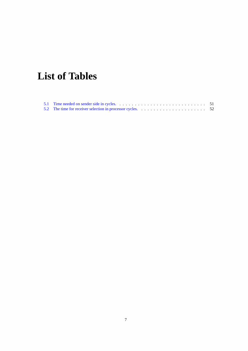
5.1 Time needed on sender side in cycles.. . . . . . . . . . . . . . . . . . . . . . . . . . . . 515.2 The time for receiver selection in processor cycles.. . . . . . . . . . . . . . . . . . . . . 52
7

8 LIST OF TABLES
Chapter 1
Introduction
For years operating systems were built using a monolithic kernel containing all needed functionality inone large piece of software. In contrast, the microkernel development, started in the 1980s, focuses onminimizing the kernel to a minimal set of abstractions and implement all remaining operating-system func-tionality as servers at user level. Ideally, a microkernel provides only address spaces (protection domains),threads (the active entities inside an address space), and communication between threads (inter-processcommunication, IPC).
Servers and applications implemented on top of the microkernel execute in their own address space.Communication between servers and applications uses the kernel-provided IPC mechanism. Therefore theperformance and functionality of the IPC mechanism is important for microkernel-based systems.
System-wide security policies require the control of communication relationships. Certain constraintson the flow of information are imposed and need to be enforced. This means that both the direct communi-cation of task and their access rights to objects need to be controlled. The absence of the latter would allowfor indirect communication via a shared resource. To achieve the aforementioned objectives a semanticallywell defined, general and efficient control mechanism is needed. In this thesis I refined and implementedsuch a mechanism.
Generalized Mappings is devised upon the ideas of the L4 memory management scheme. Resourcesare referred to by local names only and access rights can be transferred. The coverage of new notionsas send rights required the extension of the existing name space. Originally only virtual addresses wereused as name space. The existence of objects beyond page frames required an additional naming scheme.Capabilities as opaque handles to objects of various classes fulfill this role. The manipulating operations(map, grant, unmap) can be applied the same way as for memory objects.
This thesis refined an initially vague model and evaluated its appropriateness on a prototypical imple-mentation. The results confirmed its feasibility.
1.1 Organization of this Document
This thesis is organized as follows. In the next chapter I describe the background of this thesis. I introducemicrokernels, access-control mechanisms and the L4 memory model. In Chapter3, I present the designof the Generalized-Mapping IPC mechanism. First, I describe the requirements for the IPC mechanism,then the mechanism itself. Chapter4 explains the prototypical implementation. Furthermore, I discussalgorithms for receiver selection. I evaluate the performance of the new IPC mechanism in Chapter5.Finally, I conclude this thesis in Chapter6 and give an outlook on future work.
1.2 Acknowledgements
This thesis would have been impossible without the support of many people. I am deeply indebted to all ofthem. First of all I would like to thank Prof. Hermann Härtig. He was the driving force behind the ideas
9

10 CHAPTER 1. INTRODUCTION
of Generalized Mappings. My special thanks go to my supervisors Christian Helmuth and Marcus Völpfor their guidance and the support they gave me during the work on this thesis. I had numerous interestingdiscussions with them. Finally thank Michael Peter, Udo Steinberg and Marcus Völp for proofreading thisthesis. Their valuable comments and feedback helped me to improve this document.
Chapter 2
Background and Related Work
2.1 Microkernels
In operating systems, the termkerneldenotes the fundamental part used by all other software. The kernel isspecial from other software, as it runs in a special CPU mode: the kernel mode. Thus it can use all processorfeatures such as programming the memory management unit or switching tasks. Software running in usermode cannot perform such security-critical operations.
Many operating systems, such as Linux [22] or Windows [31], are based on a monolithic kernel. Such akernel contains all operating-system services, including file systems, device drivers, network stacks, mem-ory management, scheduling and others, packed together into a single kernel. Thereby all these services runin kernel mode. One malfunctioning or hostile component can corrupt and even crash the whole system.
In contrast, the key idea of microkernels is to provide only a minimal set of abstractions in the kerneland implement all additional functionality as servers at user level. Ideally, the microkernel implementsonly address spaces, inter-process communication (IPC) and basic scheduling [20]. All remaining op-erating system components and services, even device drivers, are user-level programs. Because each ofthese components executes in its own address space, they are protected from each other. This design al-lows for more robust operating systems because a malfunctioning service does not hamper the remainingcomponents. Furthermore, this design approach helps to reduce the trusted computing base (TCB) to thehardware, the microkernel and basic services, such as a basic memory manager, a screen driver, a keyboarddriver, and perhaps a disk driver and a file system.
The first generation of microkernels and its flagship Mach [1], however, suffered from flexibility andperformance problems. Mach was a refactored Unix kernel and it was not really small (more than 140system calls, more than 300 KB code). It provided a rich featured IPC mechanism with authorization,message buffering and a complex message format. Mach also invented the innovative concept of externalpagers that allows to implement memory management strategies outside the kernel. However, due to theenormous size and the sophisticated IPC mechanism, the Mach microkernel had poor performance.
The designers of the second generation of microkernels learned from the errors of the first generationand designed their kernel for achieving performance. Liedtke constructed his L4 microkernel from scratchwith the goalsIPC performance is the Master[15] and minimality [19]. This design methodology leads tosmall-sized kernels with high performance.
The L4 Microkernel
The original L4 microkernel interface [18] was designed for the x86 architecture and written completely inassembly language [17]. L4 provides only three abstractions: address spaces (protection domains), threads(the executing entities in an address space) and synchronous inter-process communication (IPC) betweenthreads. Furthermore, the kernel provides a scheduler with multiple fixed-priority levels, whereby threadswith the same priority are scheduled in a round-robin fashion.
All software developed during this thesis runs on top of the Fiasco microkernel, an implementation ofthe L4 interface developed by Michael Hohmuth at TU-Dresden [7, 4]. Fiasco is fully binary compatible to
11
12 CHAPTER 2. BACKGROUND AND RELATED WORK
the original L4 kernel. Furthermore, Fiasco provides a powerful in-kernel debugger and a port to the linuxsystem-call interface [5]. Therefore, Fiasco is an excellent basis for software development for L4.
2.2 Access Control
Access Control is a key mechanism for constructing trusted secure operating systems. The access-controlmechanism enforces the defined access-control policy of a system. The access-control policy defines andrestricts the ability of asubjectto invoke certain operations on anobject.
Objects are the resources of the system. These objects can be physical resources, such as memory,CPUs, devices and other hardware, or logical resources, such as processes, communication channels, filesor system calls. Certain operations can be invoked on objects depending on the object type. For example,files can be read and written to, but system calls can only be executed. Therefore, objects need to beprotected [13] from unauthorized or invalid accesses.
Subjects are the active entities that access objects. In computer systems, subjects are usually processesacting on behalf of a user. Subjects can have access rights on objects to access and use these objects.However, subjects can also be potentially untrusted, for example user-supplied or downloaded programcode.
So a way is needed to prohibit subjects from accessing objects that they are not authorized to access.The provided mechanism must also allow for restricting the allowed operations a subject can use on anobject. For example, a taskT may be authorized to read a fileF , but not to write to that file. The access-control mechanism must ensure that the desired access-control policy cannot be bypassed. A subject’saccess to an object must not succeed if that access violates the policy.
The relationship between subjects and objects regarding the object access can be represented with thetriple (subject, object, rights). Such a triple specifies the subject’s rights on an object. These triples aredefined by the system’s access-control policy and are used by the access- control mechanism to enforce thepolicy.
2.2.1 Access Matrix
A possible way to store the access triples is the access matrix. The access-matrix rows consist of thesubjects; the columns are the objects. An entry inside the matrix controls the access rights from a subjectto an object. Whenever a subject tries to access an object, the access control mechanism checks the matrixentry whether the requested operation is allowed or not.
The main problem with the access matrix is its enormous size: The matrix needs one entry per (subject,object) pair. Also the matrix is usually sparsely populated (most subjects need and have only access to somefew objects). So storing the entire, mostly empty, matrix would waste memory and disk space. Therefore,the idea is to store only the relevant parts of the matrix. Two methods are common: Storing the nonemptyelements by column or storing them by row. The first method is called anaccess control list. The secondmethod is called acapability.
2.2.2 Access Control Lists
An access control list (ACL) consists of all nonempty elements from a matrix column. Every ACL entryis a tuple (subject, rights). The ACL is stored together with the object it belongs to and specifies whichsubject can access that object in which way.
When a subject tries to invoke an operation on an object, the object’s ACL is traversed to check whetherthe subject may invoke the requested operation or not. If more than one entry matches the subject, the firstentry found is used. Therefore the access control list must be kept sorted by some metric. A commonmetric, used in the Unix file system, is to store entries regarding individual users at the beginning, followedby entries regarding groups of users (sometimes called roles). Default entries are stored at the end. Withthis metric a particular user can have less rights than a group it is in.
Since ACLs are stored together with the object, it is easy to figure out which subject can invoke whichoperations on that object. Only the ACL has to be analyzed for that. The revocation of rights is also
2.2. ACCESS CONTROL 13
Server RightsObject f(Object,Rights,Check)
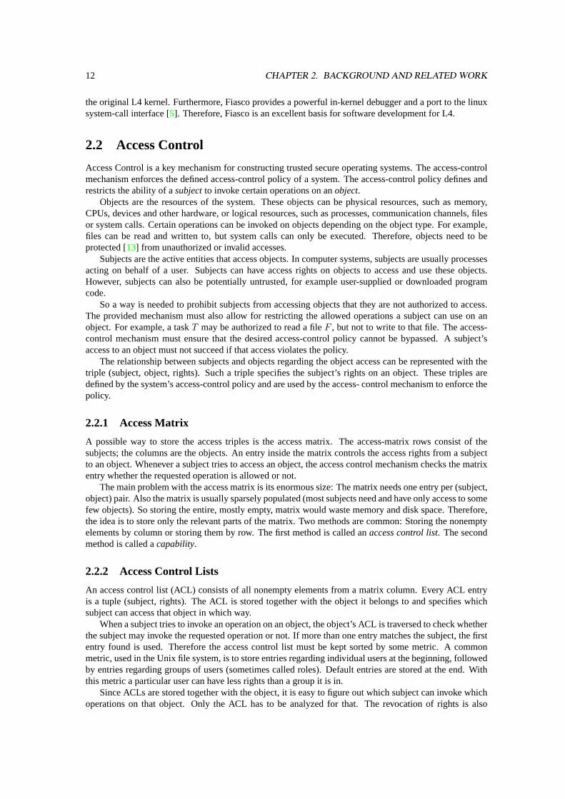
Figure 2.1: A cryptographically-protected Amoeba capability.
uncomplicated: Now unwanted operations are removed from every subject’s ACL entry. To revoke theaccess of a subject completely, the ACL entry is removed. However, care has to be taken when a subjectcan act also with a role account (e. g., a Unix group). Then the subject’s entry must not be removed. Insteadit must allow for no operation (remember also the metric described afore).
A problem with ACLs is their limited ability for access delegation. For each subject wanting access(temporarily) a new entry has to be added. After accessing the entry has to be removed again.
Access control lists are commonly used in file systems, such as the Unix file system, or the Win-dows 2000 file system.
2.2.3 Capabilities
When storing the rows from access matrix we talk aboutcapability listsconsisting ofcapabilities. Acapability is a tuple (object, right) assigned to a subject.
The capability grants its owner certain access rights on an object. Thereby the object used is encodedin the capability; the subject specifies only the capability to use and the operation. To check whether therequested operation is allowed or not only the capability is inspected. No list traversing as with ACLs isneeded.
Because capabilities are given to subjects, which are potentially malicious, they must be protected fromtampering. Three different methods are known: First, capabilities can be protected by hardware. The Cam-bridge CAP Computer [24] uses different segment types for data segments and capability segments. Thesegments can be accessed only with instructions belonging to the segment type. Arithmetical and logicalinstructions can be used only on data segments. Capability related instructions work only on capabilitysegments.
Second, capabilities can be protected by the operating system. Here only the operating system itselfcan access the capabilities directly, user applications only receive a handle, a local name, for the capability.A common example are file descriptors in Unix: The process uses a handle (the file descriptor) to invokeoperations (read, write, seek) on a file. In Hydra [32] and in EROS [25] capabilities are protected by theoperating-system kernel.
The third way is to store capabilities in user space but protect them from tampering using cryptography.This approach is used in distributed systems such as Amoeba [29]. An Amoeba capability [28], shown inFigure2.1, encodes the server the capability belongs to, an object there and the access rights to that object.The last field is the result of a cryptographically strong one-way hash function wherebyCheckis a secretonly known to the server. When the capability owner wants to access the object, it sends the request andthe capability to the server. The server recalculates the hash using the object and rights fields from thetransmitted capability and its internally stored check. Object access is only granted when the recalculatedhash value matches the hash value from the capability. Not matching hashes indicate an altered or even aself-created capability. In this case the access is denied and the request is discarded.
Using capabilities allow for an elegant way of access delegation: One subjectS can give a capability itowns to another subjectR. TherebyS can restrictR’s access rights to the object the capability referencesto a subset of its own access rights. AfterwardsR can also access the object using its capability copy.
However, because capabilities are given to a subject and that subject can give copies to other subjects,the revocation of granted access rights (capabilities) is difficult. It is hard to find all outstanding copies,especially in distributed systems as Amoeba. One approach is to have an indirection object: Rather thanpointing to the object itself, all capabilities point to the indirection object. Capability revocation is done bydestroying the indirection object. This object becomes invalid, and thus all capabilities regarding to it too.EROS provides this method; the indirection objects are calledwrappersthere.
14 CHAPTER 2. BACKGROUND AND RELATED WORK
Hardware, MMU
Policy 1 Policy 2
Monolithic Kernel
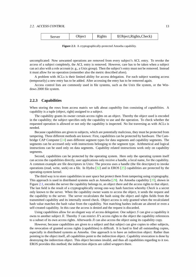
Figure 2.2: Memory management policies in a monolithic kernel.
Hardware, MMU
Policy 2Policy 1
Microkernel
X
X
Figure 2.3: Memory management policies in a microkernel-based system.
Another way for revocation is possible in the Amoeba scheme: A server can change the check fieldit stores with the object. Immediately, all existing capabilities encoded with the old check value becomeinvalid. However, neither of these mechanisms allow to revoke capabilities selectively from one subjectbut not from another.
2.3 The L4 Memory Model
In this section I will introduce the L4 memory model, the ideas behind it and the provided mechanisms.The separation of address spaces to protect tasks from each other is important in operating systems as it
is necessary for fault isolation and data protection. The basic mechanisms for address-space separation areprovided by the hardware’s memory management unit (MMU). Since programming the MMU is criticalfor system security, it can only be done in kernel mode but not in user mode. Therefore the kernel has toprogram the MMU and the structures used by the MMU.
In monolithic kernels the kernel does the entire memory and address space management. The kernel ispart of the TCB, and because the kernel must be trusted anyway, this implementation is safe from a securityperspective. The kernel also defines the policy used for memory management. However, kernel-definedpolicies are rather static, the applications can at most select from the provided strategies. Implementingadditional application-specific management policies requires a kernel change to insert a new policy into thekernel. Another problem with this approach is the lack of isolation between the different provided policies:One malfunctioning policy module can harm the other modules and their client applications. This problemis illustrated with dashed lines in Figure2.2.
The microkernel approach addresses these problems. Here only the fundamental management, theprogramming of the hardware, is done by the kernel. The kernel exports an interface for modifying thememory management structures to user level. The management policy is implemented purely at user levelusing this kernel-provided interface. So any required memory management strategy can be implemented
2.3. THE L4 MEMORY MODEL 15
map IPC
Receiver
receive(’map’, virtual address in R)
Sendersend(’map’, virtual address in S, max access)
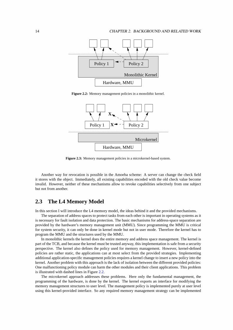
Figure 2.4: A page is mapped using IPC.
at user level. New policy implementations do not require a kernel change. Because of the address-spaceseparation, a faulty memory-management policy provider can only harm its clients but not other policyproviders and their clients, see Figure2.3.
With this approach it is even possible to stack multiple policy providers: For example, a base memoryprovider hands out pages using a cache-coloring scheme. The next-level provider then does demand pagingfor its clients. In the L4 microkernel the scheme of recursive address-space construction is used for stackedmemory managers.
2.3.1 Recursive Virtual Address Space Construction
The L4 kernel provides mechanisms for the recursive construction of address spaces outside the kernel[17]. These mechanisms allow a thread from one address space to give access to its pages to another threadin another address space.
The kernel enforces the security restrictions on this operation: Only pages the sender has access to canbe given to the receiver. This restriction prevents from gaining access to arbitrary memory pages. It isachieved by using virtual page numbers for the operation. The other important restriction is that the sourcethread can grant at most the rights it has itself on a page to the receiver. So privilege elevation, for exampleupgrading a page from read-only to read-write, is prevented. However, downgrading the access rights,for example from read-write to read-only, is an allowed operation. Hence, the L4 model for constructingaddress spaces is safe because the kernel enforces the aforementioned restrictions during page transfer andbecause only the kernel programs the MMU hardware.
The recursive address space construction starts from an initial address space calledσ0. The kernelcreates this address space with an idempotent mapping from virtual to physical pages during system start.It owns all memory except the parts the kernel uses itself. All other address spaces are created empty.
To recursively construct address spaces the kernel provides the three operationsmap, grantandunmap.
Map and Grant
A thread from an address space canmapany of its pages to another address space if the recipient agrees.The mapped pages are inserted into the recipients address space. Afterwards the mapped pages are acces-sible in both the mapper’s address space and the recipient’s address space.
A thread from an address space can alsogrant any of its pages to another address space if the recipientagrees. The granted pages are inserted into the recipients address space. However, in contrast to map, thegranted pages are removed from the granter’s address space.
Both operations, map and grant, require an agreement between the source thread and the recipientthread. Therefore these operations are implemented using IPC: The sender specifies the map or grantoption inside the message and provided the virtual address of the page to send and the receiver’s maximumaccess rights to that page. Remember, the kernel maps or grants at most the actual rights from the sender.The receiver waits for a map message and specifies the virtual address a received page is mapped or grantedto in its address space. This map IPC is illustrated in Figure2.4.
With the map and the grant operation, L4 has an elegant way to delegate access rights to memory pagesfrom one address space to another.
16 CHAPTER 2. BACKGROUND AND RELATED WORK
A
BC
D
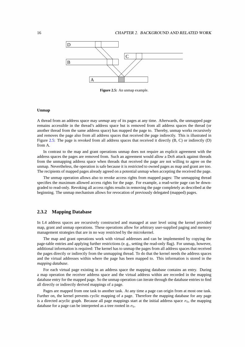
Figure 2.5: An unmap example.
Unmap
A thread from an address space mayunmapany of its pages at any time. Afterwards, the unmapped pageremains accessible in the thread’s address space but is removed from all address spaces the thread (oranother thread from the same address space) has mapped the page to. Thereby, unmap works recursivelyand removes the page also from all address spaces that received the page indirectly. This is illustrated inFigure2.5: The page is revoked from all address spaces that received it directly (B, C) or indirectly (D)from A.
In contrast to the map and grant operations unmap does not require an explicit agreement with theaddress spaces the pages are removed from. Such an agreement would allow a DoS attack against threadsfrom the unmapping address space when threads that received the page are not willing to agree on theunmap. Nevertheless, the operation is safe because it is restricted to owned pages as map and grant are too.The recipients of mapped pages already agreed on a potential unmap when accepting the received the page.
The unmap operation allows also to revoke access rights from mapped pages: The unmapping threadspecifies the maximum allowed access rights for the page. For example, a read-write page can be down-graded to read-only. Revoking all access rights results in removing the page completely as described at thebeginning. The unmap mechanism allows for revocation of previously delegated (mapped) pages.
2.3.2 Mapping Database
In L4 address spaces are recursively constructed and managed at user level using the kernel providedmap, grant and unmap operations. These operations allow for arbitrary user-supplied paging and memorymanagement strategies that are in no way restricted by the microkernel.
The map and grant operations work with virtual addresses and can be implemented by copying thepage-table entries and applying further restrictions (e. g., setting the read-only flag). For unmap, however,additional information is required: The kernel has to unmap the pages from all address spaces that receivedthe pages directly or indirectly from the unmapping thread. To do that the kernel needs the address spacesand the virtual addresses within where the page has been mapped to. This information is stored in themapping database.
For each virtual page existing in an address space the mapping database contains an entry. Duringa map operation the receiver address space and the virtual address within are recorded in the mappingdatabase entry for the mapped page. So the unmap operation can iterate through the database entries to findall directly or indirectly derived mappings of a page.
Pages are mapped from one task to another task. At any time a page can origin from at most one task.Further on, the kernel prevents cyclic mapping of a page. Therefore the mapping database for any pageis a directed acyclic graph. Because all page mappings start at the initial address spaceσ0, the mappingdatabase for a page can be interpreted as a tree rooted inσ0.
2.3. THE L4 MEMORY MODEL 17
Microkernel
Application Pager
resume IPCpage fault
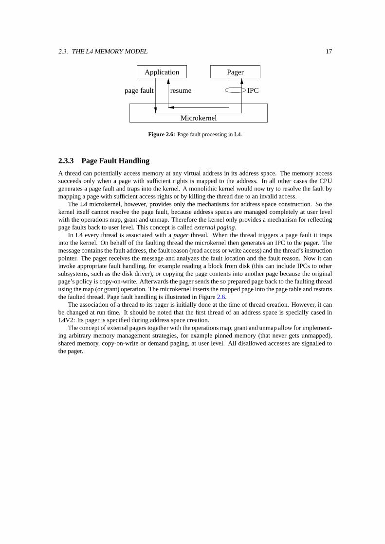
Figure 2.6: Page fault processing in L4.
2.3.3 Page Fault Handling
A thread can potentially access memory at any virtual address in its address space. The memory accesssucceeds only when a page with sufficient rights is mapped to the address. In all other cases the CPUgenerates a page fault and traps into the kernel. A monolithic kernel would now try to resolve the fault bymapping a page with sufficient access rights or by killing the thread due to an invalid access.
The L4 microkernel, however, provides only the mechanisms for address space construction. So thekernel itself cannot resolve the page fault, because address spaces are managed completely at user levelwith the operations map, grant and unmap. Therefore the kernel only provides a mechanism for reflectingpage faults back to user level. This concept is calledexternal paging.
In L4 every thread is associated with apager thread. When the thread triggers a page fault it trapsinto the kernel. On behalf of the faulting thread the microkernel then generates an IPC to the pager. Themessage contains the fault address, the fault reason (read access or write access) and the thread’s instructionpointer. The pager receives the message and analyzes the fault location and the fault reason. Now it caninvoke appropriate fault handling, for example reading a block from disk (this can include IPCs to othersubsystems, such as the disk driver), or copying the page contents into another page because the originalpage’s policy is copy-on-write. Afterwards the pager sends the so prepared page back to the faulting threadusing the map (or grant) operation. The microkernel inserts the mapped page into the page table and restartsthe faulted thread. Page fault handling is illustrated in Figure2.6.
The association of a thread to its pager is initially done at the time of thread creation. However, it canbe changed at run time. It should be noted that the first thread of an address space is specially cased inL4V2: Its pager is specified during address space creation.
The concept of external pagers together with the operations map, grant and unmap allow for implement-ing arbitrary memory management strategies, for example pinned memory (that never gets unmapped),shared memory, copy-on-write or demand paging, at user level. All disallowed accesses are signalled tothe pager.

18 CHAPTER 2. BACKGROUND AND RELATED WORK
Chapter 3
Design
Generalized Mapping, in short GM, is a new idea of the TU-Dresden’s Operating Systems Group for a next-generation L4 microkernel. The main idea behind GM is to generalize the well-understood L4 mechanismsfor memory management, the mapping and unmapping of pages, in order to use these mechanisms for allother kernel-provided resources as well. The resources provided by such an L4 kernel are memory pages,threads, tasks and communication channels.
As in current L4 kernels, a task is a protection domain. Thus a task can own resources of all the abovetypes. Threads as the active entities can invoke operations on the task’s different resources. A task has atask-local name space for each type of resource the L4 kernel provides. This allows a task to access theactual resource using local names without the need of a globally unique name1. However, when globalnames are needed, they can be implemented at user level. The local name space allows a task to managenames for resources with an arbitrary policy at user level. Furthermore, task-local names are also a steptoward resource virtualization: A locally named resource can be backed by any physical resource of thattype like it is already done with memory pages in current L4 versions.
A local name for a resource can be seen as a capability: When a task has a local name to a particularresource it can access or invoke operations on that resource. Without a name no operations can be invoked.So a local name, or a capability, allows certain operations on a resource. There are existing two types ofoperations: operations that can be used with all types of resources, and resource-specific operations.
The operations specific to a certain resource type can be invoked only on resources of that type. Theseoperations are usually bound to the resource type’s name space implicitly. So it is impossible to invokethese operations with the wrong type of resource. For example the read-memory operation always uses thevirtual address space (the name space for memory) and therefore cannot be invoked on threads from thethread name space.
General operations can be used with all types of resources. However, when such an operation is in-voked, it keeps track of the resource’s name space. Thus name spaces cannot be merged using a generaloperation. Examples for operations valid on all resource types are map and unmap.
In a system with Generalized Mappings resources are transfered from one task to another using the mapoperation. This is basically a generalization of the mapping mechanism used for memory pages With thismechanism a task can grant access rights to any of its resources to another task. During the map operationthe allowed access rights can be diminished. So the receiver of a mapping may have less rights than thesender. Widening the access rights with the map operation is not possible, because the kernel maps at mostthe sender’s actual rights, even if it specifies more.
This thesis focuses on the IPC mechanism used in a Generalized Mappings kernel. So the followingsections will discuss IPC and the IPC control mechanisms in detail.
1However, global names are needed for very special purposes e. g. physical addresses for DMA memory. So mechanisms haveto be provided to translate local names to global names when needed. As current experience with memory shows, this can be doneoutside the kernel.
19
20 CHAPTER 3. DESIGN
3.1 Requirements
In this section I will define the requirements the IPC mechanism of a kernel with Generalized Mappingsshould fulfill.
Trent Jaeger et al. [10] define the following six requirements for the system’s trusted computing base(TCB). Since the IPC mechanism is part of the TCB, it has to fulfill these requirements.
• Communication: The system must be able to restrict the ability of a process to send an IPC toanother process.
• Authentication: The system must identify the source of an IPC.
• Authorization : The system must be able to determine whether a particular operation on a particularobject should be permitted.
• Delegation: The system must be able to control the delegation of permissions from one process toanother.
• Revocation: The system must be able to revoke the ability of a process to communicate with anotherprocess or perform an operation on another process’s objects.
• Denial: The system must be able to prevent denial-of-service attacks on processes.
• Mechanism: The system must be able to implement arbitrary access control mechanisms (e. g.,optimized for the policy that they enforce) of its own choosing.
In addition to these six the following requirements came up in discussions before and during my work.
• Local names: All resources must be addressed using local instead of globally unique names. Thisallows changing of the actually used resource without changing its name. Wherever global namesare needed, they should be created at user level.
• Transparent thread structure: The client should not need to have a priori knowledge about thethread structure of a server task. This allows the server to hide its internal structure or even changeit transparently. With the new IPC mechanism one should be able to implement a wide variety ofserver structures — for example thread pools, dedicated threads per client, a server side distributionto worker threads, or single threaded servers — without having to add extra mechanisms for just thatpurpose such as auto propagation [21].
• Isolation: The provided mechanisms should allow to isolate subsystems from each other. Thus,communication restrictions must enforce that a task from one isolated subsystem is unable to com-municate with tasks from other subsystems.
• Synchronous IPC: The IPC between communication partners should be synchronous to avoid com-plex buffering of messages inside the kernel. When asynchronous communication is needed, itshould be implemented at user level.
3.2 Generalized Mappings for IPC Management
In microkernel-based systems the kernel provides the basic mechanisms for communication. Because italso provides the communication mechanism (IPC), the kernel must allow for restricting communicationbetween tasks to enforce the desired security policy. The policy itself is not defined by the kernel, it iscontrolled by user-level policy servers but enforced by the kernel. Whenever the policy changes, the policyservers must be able to update the restrictions and thus permit new communication channels or revokeexisting ones.
To achieve communication control, and thus communication restrictions, I introduce a new mechanismto the L4 microkernel: The right to send a message from one task to another task. This right is represented

3.2. GENERALIZED MAPPINGS FOR IPC MANAGEMENT 21
by a new kernel object called aTask-Send Capability, in short send capability. Possession of such acapability authorizes its owner to send messages using this capability. The send capability refers to theactual message receiver. Therfore these send capabilities establish a one-way communication channel2.When the receiver wants to reply, it also needs a send capability: a send capability referring back to thesender.
In this thesis the notation→ B is used for a send capability. With the denoted send capability messagescan be sent to taskB. To name the owner of a send capability the notationA → B is used: TaskA holds asend capability to taskB.
In order to enforce security restrictions regarding the communication between tasks, the capability mustbe protected from modification by its owner. Otherwise a task could arbitrarily forge capabilities and thussend messages it is not allowed to send according to the system’s security policy. The send capabilitiesused for GM IPC are kernel-provided objects. Therefore they are protected by the kernel. The owning taskonly gets a handle — the local name — to the send capability, the actual content is opaque to the user.This opaqueness allows for changing the capability transparently to the user because the user-visible nameremains the same.
Send capabilities solve the authorization requirement: Only tasks possessing a send capability→ B toa taskB can send massages to taskB. They are authorized to do so by a user-level policy server. Taskswithout a send capability to taskB cannot send messages toB.
Send capabilities can protect against some types of denial-of-service attacks. An attacking task withouta send capability to a target task cannot send any messages to the latter and thus it cannot carry out DoSattacks. Tasks with sufficient send capabilities can still send useless “junk” messages preventing the targetfrom doing useful work. This is not a problem, because after detection, the attacked task could ask thepolicy server to revoke the misused capability using the mechanisms described in the next sections.
Further on, send capabilities also solve the isolation requirement: Tasks inside an isolated subsystemreceive only send capabilities to other tasks inside this subsystem. So these tasks cannot send messages toother tasks outside this subsystem. Similarly, no send capabilities to tasks from the subsystem are given totasks outside the subsystem. Now only tasks inside the subsystem can send messages to other tasks withinthis subsystem. It is completely isolated from other communication.
3.2.1 Distribution of Send Capabilities
In the previous section I introduced the task-send capabilities. Now I describe the mechanisms used topropagate capabilities from one task to another. Afterwards I describe, how the well-known L4 mechanismscan be used to revoke the propagated capabilities.
A task in a system with Generalized Mappings holds some send capabilities. Each of these capabilitiespermits communication with another task. Over these established communication channels normal datamessages can be sent, but also messages containing resources such as memory pages or capabilities. So atask can send its send capabilities to another task. Afterwards, both tasks own the same capability and cansend messages using this capability. In the following this capability transfer will be calledforwardingof acapability. Of course, a task can only forward capabilities itself owns. There is no way for the creation ofnew capabilities using the forward operation.
A completely new mechanism just for capability transfers is not necessary, it would even violate theminimalistic approach of L4. The L4 IPC system-call already provides a transfer operation for resources:the map operation. So far this operation is solely used for the mapping of virtual memory pages from onetask to another. I use this operation also to transport capabilities from a sender task to a receiver task.Hence, the mapping of capabilities applies the same mechanisms as the well-known and well-understoodmapping of pages from the task’s virtual address space.
A slight extension of the L4 kernel has to be done to support a new type of flexpage, thecapabilityflexpage. Such a capability flexpage consists of a base capability Id and the size of the flexpage, just likefor normal memory flexpages. During the map operation all capabilities inside the given flexpage from thesender are inserted into the receiver’s capability structures.
2IPC error codes can be used to leak information back from the receiver to the sender. To enforce strict one-way communicationchannels, a reference monitor has to be inserted into the channel (see Section3.3.1).
22 CHAPTER 3. DESIGN
Most of the classic capability-based systems do not keep track of the forwarded capabilities. Hence,these systems cannot easily revoke a capability, because they do not know which tasks have a copy of thedesired capability (see also Section2.2.3). Some systems, EROS [25] for example, provide an indirectionlevel for the actual capability and can invalidate it there. EROS and Mach [1] provide capabilities with anuse-at-most-once semantic, e. g. the EROSreturn capability. All copies of such a return capability becomeinvalid when one of the copies is used. In Amoeba [29] capabilities are protected cryptographically (seeSection2.2.3) using a secret. Changing the secret invalidates all outstanding capabilities. Neither of thesemechanisms is able to revoke a capability selectively from a subset of tasks.
The send capabilities used for GM IPC should avoid these problems. Again, a possible solution isalready used in the L4 kernel for memory mappings. During mapping of memory pages the kernel keepstrack which page from the source address space is mapped to which location in the destination addressspace. This information is kept in the mapping database. For each physical frame the mapping databaserecords the map operations of a task and the virtual address in the destination space.
A similar database can be used to keep track of capability mappings. For each capability this databasecontains a tree3 where the capability mappings are recorded. So the kernel can keep track of all mappingoperations. Thus the kernel knows for every capability the tasks this capability is accessible from and alsothe location there. (Note: How a system is initialized and started is described in detail in Section3.2.7.The total number of initial capabilities existing in a system is also describe there).
The mapping database stores the information how the task-send capabilities are distributed amongtasks. This information can then be used to selectively revoke the capabilities a task directly or indirectlyforwarded to other tasks. For memory L4 provides the unmap system call implementing this operation.The unmap operation traverses the mapping database for the requested frame starting from the currenttask. Then the page is removed from the address space of all tasks it was mapped to from the currenttask. Furthermore, unmap works recursively through all address spaces the original receiver has mappedthe page to. This continues until the complete subtree of the mapping database is traversed and the pagesare unmapped from all tasks inside that subtree.
With the mapping database for capabilities and the aforementioned capability flexpages the unmapoperation can be extended to revoke forwarded capabilities. Hence, we also have an effective way for theselective revocation of send capabilities.
The unmap operation is safe, because a task can only unmap capabilities it owns. Furthermore, thereceiver of a capability mapping implicitly agrees to a possible unmap when it accepts the mapping. forthis reason no further authorization or agreement is necessary for the unmap call.
With the introduced mechanisms and operations the rights-delegation and rights-revocation require-ments can be solved. The map operation during IPC is used to delegate the rights from one task to another.The unmap operation together with the mapping database is used for the revocation of previously grantedcommunication rights.
3.2.2 Preventing the Unwanted Distribution of Rights
As described in the previous section, task-send capabilities are distributed between tasks by mapping themfrom one task to another. Up to now, there are no restrictions whether a task can forward its send capabilities(or other resources such as memory pages) or not. However, when the mapping operation is allowed withoutany restrictions, a new problem arises: The unwanted distribution of rights.
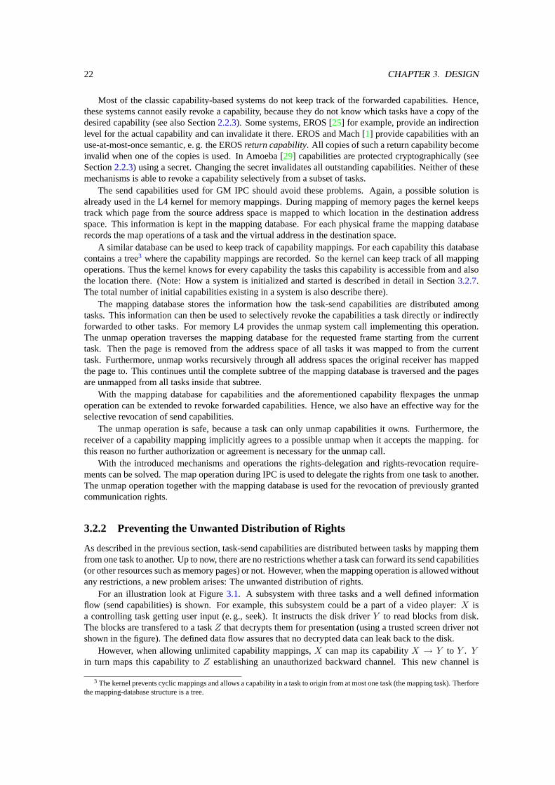
For an illustration look at Figure3.1. A subsystem with three tasks and a well defined informationflow (send capabilities) is shown. For example, this subsystem could be a part of a video player:X isa controlling task getting user input (e. g., seek). It instructs the disk driverY to read blocks from disk.The blocks are transfered to a taskZ that decrypts them for presentation (using a trusted screen driver notshown in the figure). The defined data flow assures that no decrypted data can leak back to the disk.
However, when allowing unlimited capability mappings,X can map its capabilityX → Y to Y . Yin turn maps this capability toZ establishing an unauthorized backward channel. This new channel is
3 The kernel prevents cyclic mappings and allows a capability in a task to origin from at most one task (the mapping task). Therforethe mapping-database structure is a tree.
3.2. GENERALIZED MAPPINGS FOR IPC MANAGEMENT 23
X Y Z
Figure 3.1: A subsystem with a defined information flow.
X Y Z
Figure 3.2: The same subsystem with unwanted communication channels.
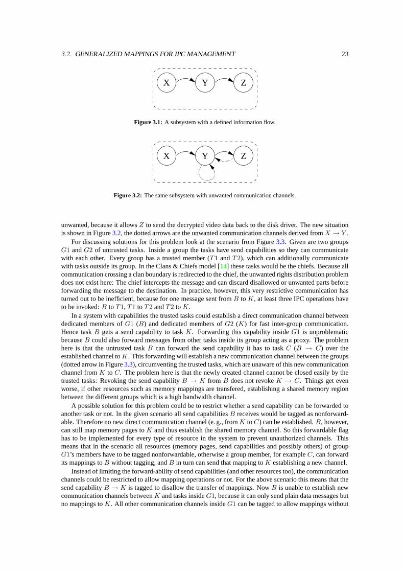
unwanted, because it allowsZ to send the decrypted video data back to the disk driver. The new situationis shown in Figure3.2, the dotted arrows are the unwanted communication channels derived fromX → Y .
For discussing solutions for this problem look at the scenario from Figure3.3. Given are two groupsG1 andG2 of untrusted tasks. Inside a group the tasks have send capabilities so they can communicatewith each other. Every group has a trusted member (T1 andT2), which can additionally communicatewith tasks outside its group. In the Clans & Chiefs model [14] these tasks would be the chiefs. Because allcommunication crossing a clan boundary is redirected to the chief, the unwanted rights distribution problemdoes not exist here: The chief intercepts the message and can discard disallowed or unwanted parts beforeforwarding the message to the destination. In practice, however, this very restrictive communication hasturned out to be inefficient, because for one message sent fromB to K, at least three IPC operations haveto be invoked:B to T1, T1 to T2 andT2 to K.
In a system with capabilities the trusted tasks could establish a direct communication channel betweendedicated members ofG1 (B) and dedicated members ofG2 (K) for fast inter-group communication.Hence taskB gets a send capability to taskK. Forwarding this capability insideG1 is unproblematicbecauseB could also forward messages from other tasks inside its group acting as a proxy. The problemhere is that the untrusted taskB can forward the send capability it has to taskC (B → C) over theestablished channel toK. This forwarding will establish a new communication channel between the groups(dotted arrow in Figure3.3), circumventing the trusted tasks, which are unaware of this new communicationchannel fromK to C. The problem here is that the newly created channel cannot be closed easily by thetrusted tasks: Revoking the send capabilityB → K from B does not revokeK → C. Things get evenworse, if other resources such as memory mappings are transfered, establishing a shared memory regionbetween the different groups which is a high bandwidth channel.
A possible solution for this problem could be to restrict whether a send capability can be forwarded toanother task or not. In the given scenario all send capabilitiesB receives would be tagged as nonforward-able. Therefore no new direct communication channel (e. g., fromK to C) can be established.B, however,can still map memory pages toK and thus establish the shared memory channel. So this forwardable flaghas to be implemented for every type of resource in the system to prevent unauthorized channels. Thismeans that in the scenario all resources (memory pages, send capabilities and possibly others) of groupG1’s members have to be tagged nonforwardable, otherwise a group member, for exampleC, can forwardits mappings toB without tagging, andB in turn can send that mapping toK establishing a new channel.
Instead of limiting the forward-ability of send capabilities (and other resources too), the communicationchannels could be restricted to allow mapping operations or not. For the above scenario this means that thesend capabilityB → K is tagged to disallow the transfer of mappings. NowB is unable to establish newcommunication channels betweenK and tasks insideG1, because it can only send plain data messages butno mappings toK. All other communication channels insideG1 can be tagged to allow mappings without
24 CHAPTER 3. DESIGN
Group G1 Group G2
KA
T1T2
C
B
J
Figure 3.3: The unwanted distribution of rights.
implications on security because communication from and to the outside is restricted (B → K) or filteredby T1.
The tagging of communication channels introduces no new mechanism, but is a permission on thecommunication channel.
3.2.3 Capability Fault Handling
Possession of send capability authorizes communication to a particular task. The destination task is de-termined and the capability is validated during the invocation of the IPC operation. Without a propercapability the task cannot send the message. So a task may try to invoke an IPC operation using an invalidsend capability (e. g., a capability it does not own). The invocation of IPC is forbidden with this capabilityand a fault occurs. This fault that has to be handled by the GM-IPC mechanism.
There are four different causes of faults during the validity check of the used capability. First, the givenlocal name of the capability can be out of the range supported by a particular GM implementation. Second,the capability may be invalid because it is not mapped. Third, the capability may be used for an operationit is not intended for. Fourth, the capability me be lacking a required permission. The third case cannothappen with the send capabilities from this thesis because the task-send capabilities can only be used forIPC. We handle the fourth case by silently discarding mapping requests if the transfer of mappings is notallowed with the used capability.
For the first type of failure, the capability is out of supported range, the IPC operation should abort andreturn the error codeinvalid destination. Application programmers must pay attention to this condition andhandle it accordingly.
Failures of the second class occur, when a task tries to use a send capability, which is not mapped tothat task. This can happen either by using an arbitrary capability the task never possessed, or by using acapability that already got unmapped. From the kernels point of view both possibilities are the result ofinvoking IPC with an invalid capability. This resulting fault is called asend-capability fault.
In classic L4 only memory access faults, the page faults, can occur. The kernel translates the pagefault into an IPC and sends it to the faulting thread’s pager. A similar mechanism can be used for handlingcapability faults.
For handling capability faults, every thread in a GM system has a capability pager. On a capabilityfault the kernel generates capability-fault IPC and send it to the capability pager. Like a page-fault IPC,the capability-fault IPC consists of the faulting capability name and the instruction pointer where the faultoccurred. The capability pager inspects the message and extracts the faulting capability name. Then thepager resolves the fault by mapping an appropriate capability to the faulting task. Afterwards the faultingoperation is restarted,

3.2. GENERALIZED MAPPINGS FOR IPC MANAGEMENT 25
This type of error handling is transparent to the faulting thread, such as page faults are today. It is usefulto fulfill parts of the transparency requirement: A pager can revoke capabilities from its clients at any time.During the next IPC operation a fault is generated, and the pager can send another capability back to theclient. Without further interaction, the client now sends to another task as before the replacement. Thismechanism can be used when server tasks need to be restarted, when splitting a large server into smallerones, or when joining several server tasks into one task. Moreover, in Section3.3.1I show in detail, how acommunication interceptor (e. g., a debugger) can be inserted into an existing communication channel.
However, with the described revoke and fault-in mechanism one might not be able to build systems witharbitrary capability distribution between tasks. For example, a system is built, where a client sends a replycapability together with its request to a server. Before the server replies, the client revokes that capability.In the scheme above, there is no chance for the server to detect that the capability is lacking, hence theserver faults. To eliminate this fault, the server must detect the missing capability. The only reliable checkfor the validity of the capability can be done during the IPC operation. But instead of generating a faultIPC and restart the faulting IPC afterwards, the IPC operation returns an error code. This error code can beused by the server to do the appropriate error handling.
For the discussed reasons, a system implementing the Generalized Mappings IPC mechanism shouldprovide both types of error handling, transparent fault IPC with restart and IPC abort with error code.
3.2.4 Local Id’s on the Sender Side
In the preceding sections I introduced the task-send capabilities and their handling in general. In this sectionand in the following sections I describe how these send capabilities are actually used for the communicationbetween threads.
To use the send capabilities a sender thread needs to name the capability it wants to use for sending themessage. Since a task, and thus the threads within, can own many different send capabilities, the sendingthread must be able to distinguish between the different send capabilities using different names. Hence,every task requires a name space for naming the send capabilities: thesend-capability name space. Likethe name space for memory, the virtual address space, the send-capability space is local per task. Thisenables a task to manage the capability name space on its own, applying any policy for the send-capabilitynaming it wants.
The send-capability space is indexed by natural numbers. Every number represents a slot for one sendcapability. A slot is either empty, no capability is mapped there, or it contains a valid send capability. Inthe following the termcapability Id is used for the slot number. For a sender, the capability Id representsa send capability, and thus a communication channel. Since every task has its own send-capability namespace, the capability Id’s are also local per task. Different tasks can have different send capabilities at thesame capability Id. The capability Id can be interpreted (and of course used) also as the senders local nameof the intended receiver of messages sent using this capability Id.
The send-capability map and unmap operations described in Section3.2.1work within the capabilityspace. Both operations use capability flexpages consisting of a base capability Id, and the size of theflexpage. As the base address in memory flexpages the base capability Id is aligned according to theflexpage size.
The send-capability name space also solves some of the defined requirements. It allows a task to usearbitrary local names for their communication partners. Further, together with map and unmap operationthe send-capability space provides the transparency of the actual message receiver: The sender’s pagercan revoke a send capability at any time. Later, when resolving the according capability fault, the pagercan forward another send capability to the sender. The sender does not notice this change of the receiver,because the sender’s local name remains the same. Refer to Section3.3.1for an example.
3.2.5 Local Id’s on the Receiver Side
Task-send capabilities authorize the communication from a sender to a receiver as described. Consequently,when a task receives a message, it knows that the sender was allowed by an authority to send the message.The problem now is, how the receiver can identify the source of the received message. Or, in other words,how it can figure out, which of all possible senders actually sent the message.
26 CHAPTER 3. DESIGN
This sender identification provided to the receiver must be unforgeable by the sender, otherwise amalicious sender can spoof it and send messages pretending to be another task. That’s why the reliabilityof the identification must be enforced. In Generalized Mappings the kernel is a trusted entity, therefore thekernel provides the mechanisms for enforcing an unforgeable identification.
A naive approach would be the transmission of the sender’s thread Id like in current L4. This solvesthe identification problem and can also be useful for accounting purposes. But it violates the transparencyrequirement and the idea of Generalized Mappings, where global Id’s should be omitted if they are notneeded for very special purposes (e. g., DMA memory). Therefore another mechanism is needed for senderidentification.
The solution I propose for GM IPC is that every message gets an unforgeable identifier stored inside thecapability used to send the message. Since the capabilities are kernel-protected objects, the sender cannotforge this identifier. This identifier is called theprincipal Id, in shortPID. I do no call it sender Id becausethis would imply a particular use. The PID can be used for other purposes as described below.
For the kernel the PID is an opaque bit string of lengthn . The bits do not have a special meaning forthe kernel. On IPC these bits are inserted into the message by overwriting the firstn bits of the message.So the first part from a received message,n bits, is enforced through the kernel and unforgeable by thesender.
The receiver can interpret the PID in any manner. For example, a receiver uses the PID only foridentifying the sender, thus the PID is a sender Id. When replying to the sender, the receiver maps thereceived PID to one of its send capabilities. More complex receivers can use the PID as object identifiers(file descriptors for example) the message content has to be applied to. Since the PID is unforgeable, thereceiver can trust the object Id without further checks. Another possibility is the encoding of the functionId the receiver calls with the message. For more scenarios and examples refer to Section3.3.
The PID solves the authentication requirement, because it is unforgeable inserted into every message.It also gives the receiver a local name space for its requesters. The remaining questions now are, how theprincipal Id’s are managed, who manages them, and how they are placed into the send capabilities.
PID Management
The principal Id comes from the send capability. So the actually used PID has to be inserted into thecapability. Send capabilities are forwarded from one task to another using the map operation. Duringthis map operation the forwarding task specifies the PID and its length. These values are inserted into theforwarded capability.
But this PID insertion mechanism must prevent a task from forwarding send capabilities with an ar-bitrary PID. Otherwise a malicious task can insert any PID when forwarding a send capability, and thusrendering the PID useless for any kind of identification. Therefore only new bits can be appended to thePID. The already existing PID bits from the original send capability are inserted into the newly speci-fied PID. The new PID length is the maximum of the PID length of the existing capability and the newlyspecified length during capability forwarding.
So the pagers in a pager hierarchy can build a hierarchic PID space by specifying some more bits of thePID when forwarding a send capability to the next pager.
Acting on Behalf
In classic L4 with Clans & Chiefs the Chief of a Clan can send messages to tasks outside that Clan pre-tending to be sent by any task inside this Clan. This is necessary, as every message a task inside the Clansends to the outside is redirected to the Chief. When the Chief then forwards the message to the intendeddestination, it acts on behalf of the original sender.
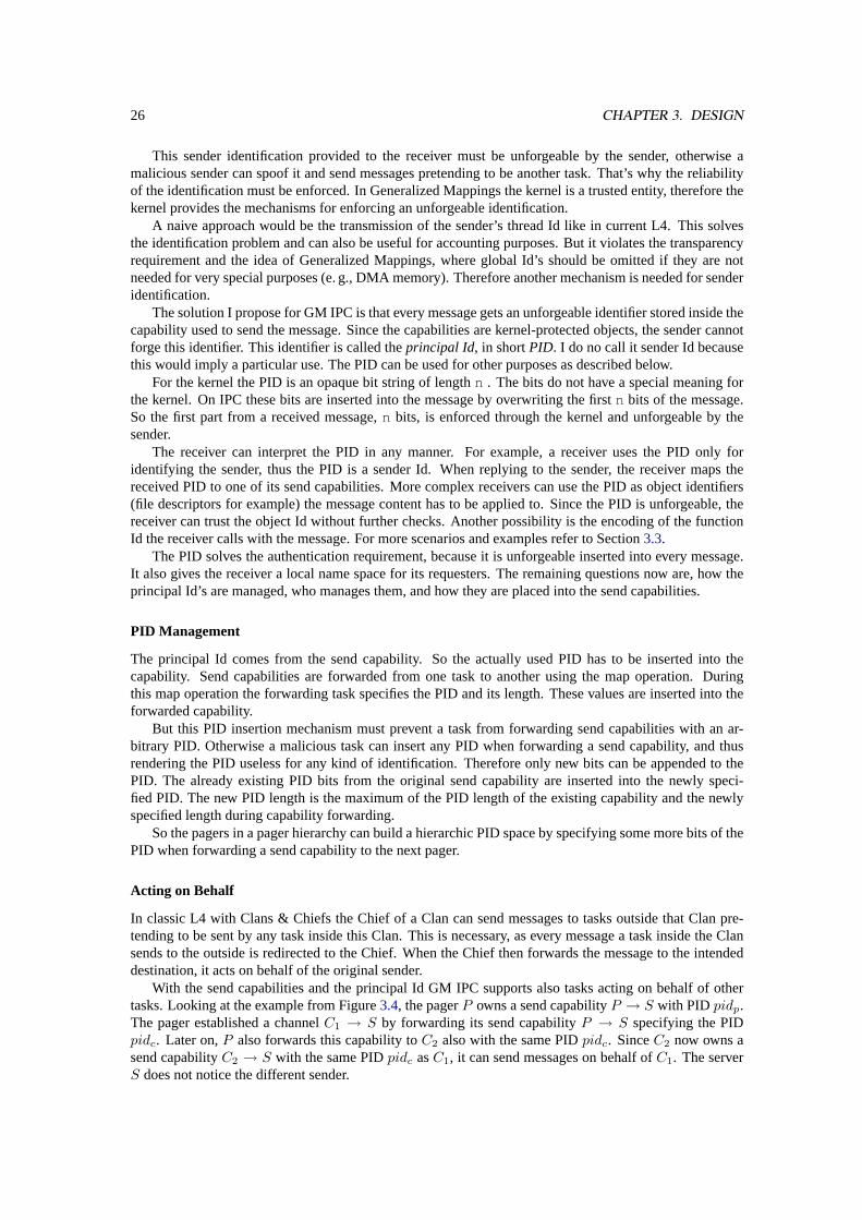
With the send capabilities and the principal Id GM IPC supports also tasks acting on behalf of othertasks. Looking at the example from Figure3.4, the pagerP owns a send capabilityP → S with PID pidp.The pager established a channelC1 → S by forwarding its send capabilityP → S specifying the PIDpidc. Later on,P also forwards this capability toC2 also with the same PIDpidc. SinceC2 now owns asend capabilityC2 → S with the same PIDpidc asC1, it can send messages on behalf ofC1. The serverS does not notice the different sender.
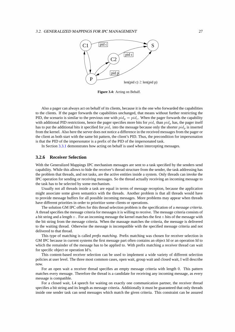
3.2. GENERALIZED MAPPINGS FOR IPC MANAGEMENT 27
P
C1
C2
S
>_len(pid c) len(pid p)
pid c
pid c
pid p
Figure 3.4: Acting on Behalf.
Also a pager can always act on behalf of its clients, because it is the one who forwarded the capabilitiesto the clients. If the pager forwards the capabilities unchanged, that means without further restricting thePID, the scenario is similar to the previous one withpidp = pidc. When the pager forwards the capabilitywith additional PID restrictions, hence the pager specifies more bits forpidc thanpidp has, the pager itselfhas to put the additional bits it specified forpidc into the message because only the shorterpidp is insertedfrom the kernel. Also here the server does not notice a difference in the received messages from the pager orthe client as both start with the same bit pattern, the client’s PID. Thus, the precondition for impersonationis that the PID of the impersonator is a prefix of the PID of the impersonated task.
In Section3.3.1demonstrates how acting on behalf is used when intercepting messages.
3.2.6 Receiver Selection
With the Generalized Mappings IPC mechanism messages are sent to a task specified by the senders sendcapability. While this allows to hide the receiver’s thread structure from the sender, the task addressing hasthe problem that threads, and not tasks, are the active entities inside a system. Only threads can invoke theIPC operation for sending or receiving messages. So the thread actually receiving an incoming message tothe task has to be selected by some mechanism.
Usually not all threads inside a task are equal in terms of message reception, because the applicationmight associate some given semantics with the threads. Another problem is that all threads would haveto provide message buffers for all possible incoming messages. More problems may appear when threadshave different priorities in order to prioritize some clients or operations.
The solution GM IPC offers for this thread selection problem is the specification of amessage criteria.A thread specifies the message criteria for messages it is willing to receive. The message criteria consists ofa bit string and a lengthn . For an incoming message the kernel matches the firstn bits of the message withthe bit string from the message criteria. When the massage matches the criteria, the message is deliveredto the waiting thread. Otherwise the message is incompatible with the specified message criteria and notdelivered to that thread.
This type of matching is calledprefix matching. Prefix matching was chosen for receiver selection inGM IPC because in current systems the first message part often contains an object Id or an operation Id towhich the remainder of the message has to be applied to. With prefix matching a receiver thread can waitfor specific object or operation Id’s.
This content-based receiver selection can be used to implement a wide variety of different selectionpolicies at user level. The three most common cases, open wait, group wait and closed wait, I will describenow.
For an open wait a receiver thread specifies an empty message criteria with length 0. This patternmatches every message. Therefore the thread is a candidate for receiving any incoming message, as everymessage is compatible.
For a closed wait, L4 speech for waiting on exactly one communication partner, the receiver threadspecifies a bit string and its length as message criteria. Additionally it must be guaranteed that only threadsinside one sender task can send messages which match the given criteria. This constraint can be assured

28 CHAPTER 3. DESIGN
with a proper PID distribution: The first part of the message is used for prefix matching with the messagecriteria. On sender side, the first message part is also the part that is replaced with the principal Id fromthe capability. So the PID is one part of the message which matched with the message criteria. When thereceiver can trust the sender’s pager, i. e. the pager does not map the send capability with the same PID toother tasks, a closed wait for one sender can be assured.
The third common case is called group wait. Here the receiver thread also specifies a bit string andlength as message criteria. Although, in contrast to closed wait, the specified criteria has a shorter length,and thus suits to several incoming messages. Again, with proper PID distribution group wait can be used towait for messages coming from a group of other tasks, but not from tasks outside that task group. Anotherexample are threads of receiver tasks, which use the first message part as an object Id. Group wait canbe used for waiting on messages regarding to any object out of group of objects. For an example refer toSection3.3.2.
Together with the described hierarchical PID distribution, the content-based receiver selection providesprotection from some types of denial-of-service attacks. All messages of an attacking sender containing itsPID. Thus, this sender can carry out a DoS attack only against receiver threads waiting for messages withthe senders PID or a shorter subset thereof. Of course, as today too, open-waiting threads are also affectedby a DoS attack. All other threads are not affected by the attacking sender.
Considerations for Multiple Receiver Threads
As described, threads waiting with a specific message criteria. The kernel chooses the actual receiverby comparing the first bits of the incoming message with the message criteria of each receiving thread.For multi-threaded receivers it is possible that the criteria of more than one thread matches the incomingmessage. This happens either when several threads are waiting with the same message criteria or when onewaiting thread specifies a prefix of another thread’s criteria.
In both cases the kernel has to choose one out of all possible receivers. In the first case, several threadswith the same message criteria, all possible threads are equal from the kernel’s point of view. Choosing thelast running thread for receiving the message is a good idea here, because the working set of this threadmay still reside in the cache. Thus this choice can outperform the selection of another thread.
For the second case, choosing the first fitting thread, or even a random one, is also not a good idea,because with such a strategy there is absolutely no control to which thread the message is actually delivered.A more deterministic way is that the thread with the most specific message criteria gets the message. Theidea thereby is that this thread might have more a priori knowledge about the message than the otherthreads. Thus it can benefit from the kernels choice. Another point is that threads with a shorter messagecriteria accept a wider range of messages. Choosing a thread with a longer message criteria does not blockthe reception of other messages out of this range. The more specific receiver cannot receive these messagesdue to its longer message criteria.
This afore described selection mechanism can be used to implement thread pools. Many threads arewaiting with the very same criteria. An incoming message with this content is delivered to one waitingthread out of the pool using LIFO selection. No further special mechanism, such as auto propagation [30],is needed for just that purpose. Answering back to the sender is not an issue, because the needed sendcapability is owned by the task. Each thread can use it for replying.
Another example are worker threads. Here, only one thread receives messages from task-externalsources. Then it analyzes the message content and forwards the message to another local thread that doesthe actual work. This allows a task to implement arbitrary message distribution at user level based on thecontent. For the same reason as above, replying to the original sender is also not a problem here.
3.2.7 Starting a System
I explained the motivation and usage of the send capabilities. Now I discuss, how a system based onGeneralized-Mappings IPC starts up. Afterwards I show the effects on task creation and start.
When a system starts, the hardware is checked and initialized to a known state. Afterward the bootloader loads the kernel and possibly a couple of initial tasks into memory. Then the kernel is started,initializes itself, and takes over the control of the system. A classic L4 kernel then creates a root address
3.3. SCENARIOS 29
space calledσ0 that represents the physical memory. This address space has an idempotent mapping ofvirtual addresses to physical addresses. All other address spaces are created empty. Further on the kernelcreates two tasks: Sigma0 and the root task. Sigma0 has the address spaceσ0, therefore it is the root forrecursive address space construction. The root task starts up the rest of the system by loading and startingthe needed tasks.
This strategy can be extended for a system with Generalized Mapping IPC. The kernel has to create aninitial send-capability name spacecap0 with an idempotent mapping of send-capability Id’s to tasks. Theidempotent mapping allows for easy conversion between task Id’s and the corresponding send-capabilityId’s. No additional mechanism is needed for it. For every possible task in a system there exists exactlyone send capability incap0. All send capabilities incap0 have an empty, zero-length PID. Therefore atask havingcap0 as its send capability space can send any message to any task, because nothing inside themessage is overwritten. So this task can also impersonate all other tasks.
The question now is, which task gets the initial spacecap0. Basically there are two possibilities. First,to create an additional taskCapability0 that hascap0 as its send-capability space. Second,cap0 goes toSigma0.
In the first case, the additional task Capability0 owns all send capabilities to all tasks, hence it is theroot for capability distribution, while Sigma0 owns all the memory pages. However, this variant has achicken-egg problem: The virtual address space of Capability0 is empty, therefore a page fault is raisedimmediately after the start. Unfortunately, Sigma0 cannot send the required memory pages, because itssend-capability space is empty. A solution for preventing such a deadlock during startup is that the kernelinstantiates some initial capability and memory mappings between Sigma0 and Capability0. However,when more types of resource mappings, such as task mappings or thread mappings, come into play in thefuture, these problems get even worse.
These problems do not exist for the second variant. Here both name spaces,σ0 andcap0, are owned bySigma0. So Sigma0 is the root for both recursive address space construction and recursive send-capabilityspace construction. By the latter, Sigma0 can also partition the PID space each next-level pager manages.
The second variant is the more elegant way, because it does not add additional complexity to the kernel.Everything regarding a policy can be done at user level. Sigma0 can provide and enforce the systems basicsecurity policy by partitioning the PID space.
Creating a new Task
During system start, but also afterwards, new tasks are started. Initially, the virtual address space andalso the send-capability space of a newly created task are empty. The empty send-capability space isproblematic, because the task does not have a send capability to its pager. Therefore the task, more preciselythe kernel on behalf, cannot send fault messages to the pager. So fault handling would be impossible.
In classic L4 this problem is solved by specifying the initial pager on the task-creation system call. Sothe newly created task can (and of course will, because it does not have any code pages mapped yet) raisepage faults that are handled by the pager.
A similar strategy can be used for creating tasks in a system with the Generalized-Mappings IPC mech-anism. Here the send capability to the pager has to be specified for the task-creation system call. Thecreating task specifies one of its send capabilities, which then is mapped to the newly created task and usedthere for sending fault messages. So the new task can raise faults, and these faults are resolved by the pager.
3.3 Scenarios
3.3.1 A Message Interceptor
In this section I demonstrate how the mechanisms of Generalized Mappings can be used for the insertionof an intercepting task into an existing communication cannel. Afterwards all messages sent through thischannel can be inspected by the newly inserted task. Thereby, the interceptor insertion can be transparent
30 CHAPTER 3. DESIGN
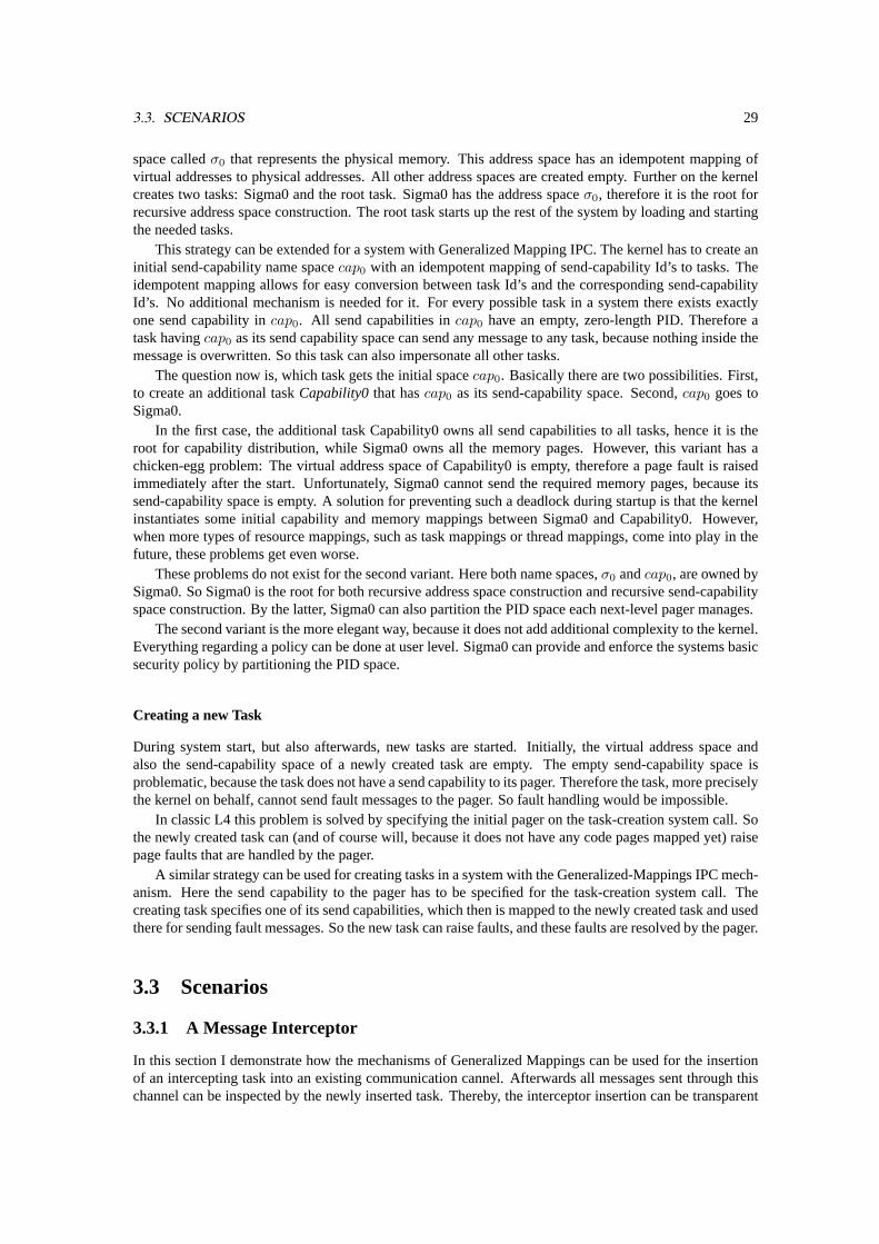
C S
P
Figure 3.5: Three tasks, client can communicate directly to the server.
C S
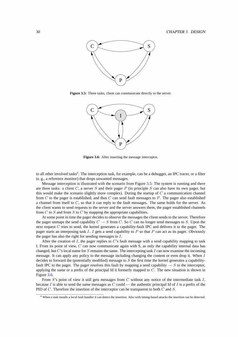
P
I
Figure 3.6: After inserting the message interceptor.
to all other involved tasks4. The interception task, for example, can be a debugger, an IPC tracer, or a filter(e. g., a reference monitor) that drops unwanted messages.
Message interception is illustrated with the scenario from Figure3.5: The system is running and thereare three tasks: a clientC, a serverS and their pagerP (in principleS can also have its own pager, butthis would make the scenario slightly more complex). During the startup ofC a communication channelfrom C to the pager is established, and thusC can send fault messages toP . The pager also establisheda channel from itself toC, so that it can reply to the fault messages. The same holds for the server. Asthe client wants to send requests to the server and the server answers them, the pager established channelsfrom C to S and fromS to C by mapping the appropriate capabilities.
At some point in time the pager decides to observe the messages the client sends to the server. Thereforethe pager unmaps the send capabilityC → S from C. SoC can no longer send messages toS. Upon thenext requestC tries to send, the kernel generates a capability-fault IPC and delivers it to the pager. Thepager starts an interposing taskI. I gets a send capability toP so thatP can act as its pager. Obviouslythe pager has also the right for sending messages toI.
After the creation ofI, the pager replies toC ’s fault message with a send capability mapping to taskI. From its point of view,C can now communicate again with S, as only the capability internal data haschanged, butC ’s local name forS remains the same. The intercepting taskI can now examine the incomingmessage. It can apply any policy to the message including changing the content or even drop it. WhenIdecides to forward the (potentially modified) message toS the first time the kernel generates a capability-fault IPC to the pager. The pager resolves this fault by mapping a send capability→ S to the interceptor,applying the same or a prefix of the principal Id it formerly mapped toC. The new situation is shown inFigure3.6.
From S’s point of view it still gets messages fromC without any notice of the intermediate taskI,becauseI is able to send the same messages asC could — the authentic principal Id ofI is a prefix of thePID of C. Therefore the insertion of the interceptor can be transparent to bothC andS.
4 When a task installs a local fault handler it can detect the insertion. Also with timing-based attacks the insertion can be detected.
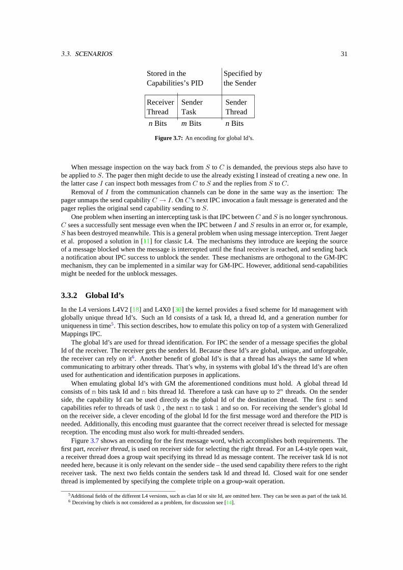
3.3. SCENARIOS 31
n Bits m Bits n Bits
ReceiverThread
SenderThread
SenderTask
Capabilities’s PIDStored in the Specified by
the Sender
Figure 3.7: An encoding for global Id’s.
When message inspection on the way back fromS to C is demanded, the previous steps also have tobe applied toS. The pager then might decide to use the already existing I instead of creating a new one. Inthe latter caseI can inspect both messages fromC to S and the replies fromS to C.
Removal ofI from the communication channels can be done in the same way as the insertion: Thepager unmaps the send capabilityC → I. OnC ’s next IPC invocation a fault message is generated and thepager replies the original send capability sending toS.
One problem when inserting an intercepting task is that IPC betweenC andS is no longer synchronous.C sees a successfully sent message even when the IPC betweenI andS results in an error or, for example,S has been destroyed meanwhile. This is a general problem when using message interception. Trent Jaegeret al. proposed a solution in [11] for classic L4. The mechanisms they introduce are keeping the sourceof a message blocked when the message is intercepted until the final receiver is reached, and sending backa notification about IPC success to unblock the sender. These mechanisms are orthogonal to the GM-IPCmechanism, they can be implemented in a similar way for GM-IPC. However, additional send-capabilitiesmight be needed for the unblock messages.
3.3.2 Global Id’s
In the L4 versions L4V2 [18] and L4X0 [30] the kernel provides a fixed scheme for Id management withglobally unique thread Id’s. Such an Id consists of a task Id, a thread Id, and a generation number foruniqueness in time5. This section describes, how to emulate this policy on top of a system with GeneralizedMappings IPC.
The global Id’s are used for thread identification. For IPC the sender of a message specifies the globalId of the receiver. The receiver gets the senders Id. Because these Id’s are global, unique, and unforgeable,the receiver can rely on it6. Another benefit of global Id’s is that a thread has always the same Id whencommunicating to arbitrary other threads. That’s why, in systems with global Id’s the thread Id’s are oftenused for authentication and identification purposes in applications.
When emulating global Id’s with GM the aforementioned conditions must hold. A global thread Idconsists ofmbits task Id andn bits thread Id. Therefore a task can have up to2n threads. On the senderside, the capability Id can be used directly as the global Id of the destination thread. The firstn sendcapabilities refer to threads of task0 , the nextn to task1 and so on. For receiving the sender’s global Idon the receiver side, a clever encoding of the global Id for the first message word and therefore the PID isneeded. Additionally, this encoding must guarantee that the correct receiver thread is selected for messagereception. The encoding must also work for multi-threaded senders.
Figure3.7shows an encoding for the first message word, which accomplishes both requirements. Thefirst part,receiver thread, is used on receiver side for selecting the right thread. For an L4-style open wait,a receiver thread does a group wait specifying its thread Id as message content. The receiver task Id is notneeded here, because it is only relevant on the sender side – the used send capability there refers to the rightreceiver task. The next two fields contain the senders task Id and thread Id. Closed wait for one senderthread is implemented by specifying the complete triple on a group-wait operation.
5Additional fields of the different L4 versions, such as clan Id or site Id, are omitted here. They can be seen as part of the task Id.6 Deceiving by chiefs is not considered as a problem, for discussion see [14].
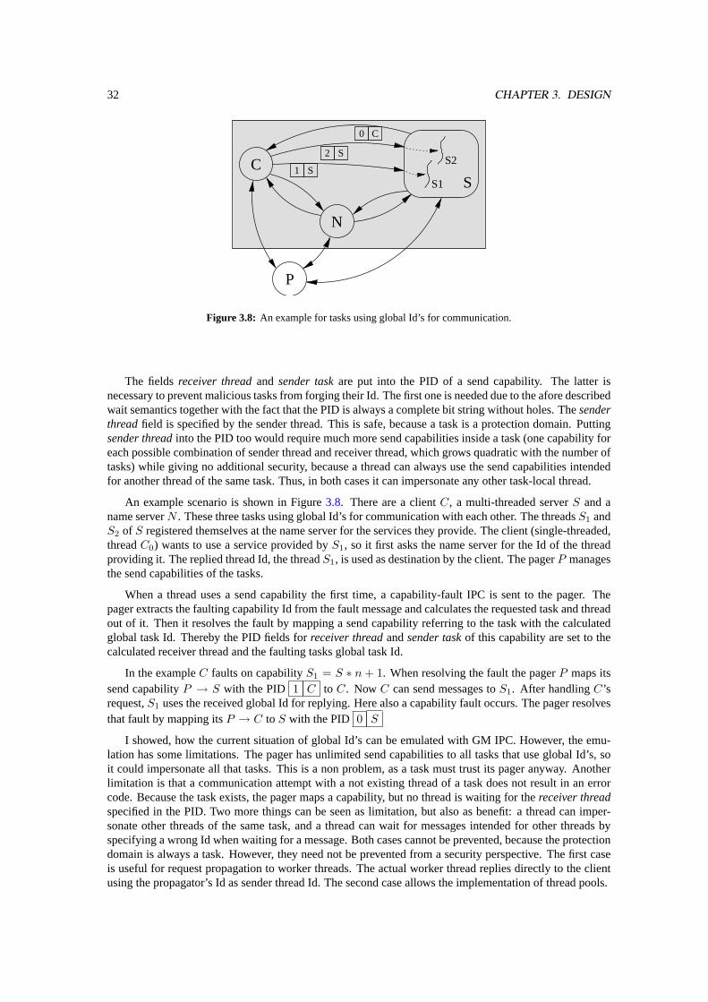
32 CHAPTER 3. DESIGN
C
P
N
S
0 C
2 S
S1S2
S1
Figure 3.8: An example for tasks using global Id’s for communication.
The fieldsreceiver threadand sender taskare put into the PID of a send capability. The latter isnecessary to prevent malicious tasks from forging their Id. The first one is needed due to the afore describedwait semantics together with the fact that the PID is always a complete bit string without holes. Thesenderthreadfield is specified by the sender thread. This is safe, because a task is a protection domain. Puttingsender threadinto the PID too would require much more send capabilities inside a task (one capability foreach possible combination of sender thread and receiver thread, which grows quadratic with the number oftasks) while giving no additional security, because a thread can always use the send capabilities intendedfor another thread of the same task. Thus, in both cases it can impersonate any other task-local thread.
An example scenario is shown in Figure3.8. There are a clientC, a multi-threaded serverS and aname serverN . These three tasks using global Id’s for communication with each other. The threadsS1 andS2 of S registered themselves at the name server for the services they provide. The client (single-threaded,threadC0) wants to use a service provided byS1, so it first asks the name server for the Id of the threadproviding it. The replied thread Id, the threadS1, is used as destination by the client. The pagerP managesthe send capabilities of the tasks.
When a thread uses a send capability the first time, a capability-fault IPC is sent to the pager. Thepager extracts the faulting capability Id from the fault message and calculates the requested task and threadout of it. Then it resolves the fault by mapping a send capability referring to the task with the calculatedglobal task Id. Thereby the PID fields forreceiver threadandsender taskof this capability are set to thecalculated receiver thread and the faulting tasks global task Id.
In the exampleC faults on capabilityS1 = S ∗ n + 1. When resolving the fault the pagerP maps itssend capabilityP → S with the PID 1 C to C. Now C can send messages toS1. After handlingC ’srequest,S1 uses the received global Id for replying. Here also a capability fault occurs. The pager resolvesthat fault by mapping itsP → C to S with the PID 0 S
I showed, how the current situation of global Id’s can be emulated with GM IPC. However, the emu-lation has some limitations. The pager has unlimited send capabilities to all tasks that use global Id’s, soit could impersonate all that tasks. This is a non problem, as a task must trust its pager anyway. Anotherlimitation is that a communication attempt with a not existing thread of a task does not result in an errorcode. Because the task exists, the pager maps a capability, but no thread is waiting for thereceiver threadspecified in the PID. Two more things can be seen as limitation, but also as benefit: a thread can imper-sonate other threads of the same task, and a thread can wait for messages intended for other threads byspecifying a wrong Id when waiting for a message. Both cases cannot be prevented, because the protectiondomain is always a task. However, they need not be prevented from a security perspective. The first caseis useful for request propagation to worker threads. The actual worker thread replies directly to the clientusing the propagator’s Id as sender thread Id. The second case allows the implementation of thread pools.
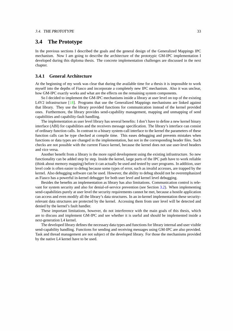
3.4. THE PROTOTYPE 33
3.4 The Prototype
In the previous sections I described the goals and the general design of the Generalized Mappings IPCmechanism. Now I am going to describe the architecture of the prototypic GM-IPC implementation Ideveloped during this diploma thesis. The concrete implementation challenges are discussed in the nextchapter.
3.4.1 General Architecture
At the beginning of my work was clear that during the available time for a thesis it is impossible to workmyself into the depths of Fiasco and incorporate a completely new IPC mechanism. Also it was unclear,how GM-IPC exactly works and what are the effects on the remaining system components.
So I decided to implement the GM-IPC mechanisms inside a library at user level on top of the existingL4V2 infrastructure [18]. Programs that use the Generalized Mappings mechanisms are linked againstthat library. They use the library provided functions for communication instead of the kernel providedones. Furthermore, the library provides send-capability management, mapping and unmapping of sendcapabilities and capability-fault handling.
The implementation as user level library has several benefits: I don’t have to define a new kernel binaryinterface (ABI) for capabilities and the receivers message specification. The library’s interface can consistof ordinary function calls. In contrast to a binary system-call interface to the kernel the parameters of thesefunction calls can be type checked at compile time. This eases debugging and prevents mistakes whenfunctions or data types are changed in the implementation, but not in the corresponding header files. Suchchecks are not possible with the current Fiasco kernel, because the kernel does not use user-level headersand vice versa.
Another benefit from a library is the more rapid development using the existing infrastructure. So newfunctionality can be added step by step. Inside the kernel, large parts of the IPC path have to work reliable(think about memory mapping) before it can actually be used and tested by user programs. In addition, userlevel code is often easier to debug because some types of error, such as invalid accesses, are trapped by thekernel. Also debugging software can be used. However, the ability to debug should not be overemphasizedas Fiasco has a powerful in-kernel debugger for both user level and kernel level debugging.
Besides the benefits an implementation as library has also limitations. Communication control is rele-vant for system security and also for denial-of-service prevention (see Section3.2). When implementingsend-capabilities purely at user level the security requirements cannot be met, because a hostile applicationcan access and even modify all the library’s data structures. In an in-kernel implementation these security-relevant data structures are protected by the kernel. Accessing them from user level will be detected anddenied by the kernel’s fault handler.
These important limitations, however, do not interference with the main goals of this thesis, whichare to discuss and implement GM-IPC and see whether it is useful and should be implemented inside anext-generation L4 kernel.
The developed library defines the necessary data types and functions for library internal and user visiblesend-capability handling. Functions for sending and receiving messages using GM-IPC are also provided.Task and thread management are not subject of the developed library. For those the mechanisms providedby the native L4 kernel have to be used.

34 CHAPTER 3. DESIGN
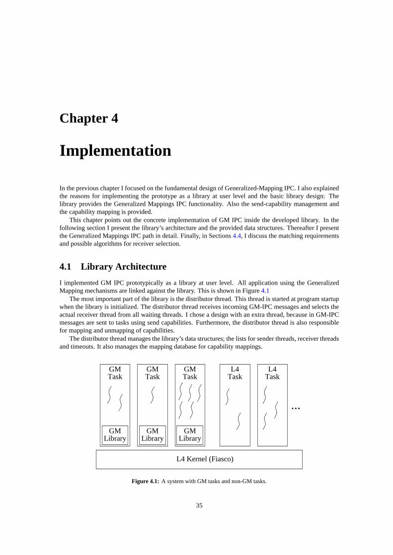
Chapter 4
Implementation
In the previous chapter I focused on the fundamental design of Generalized-Mapping IPC. I also explainedthe reasons for implementing the prototype as a library at user level and the basic library design: Thelibrary provides the Generalized Mappings IPC functionality. Also the send-capability management andthe capability mapping is provided.
This chapter points out the concrete implementation of GM IPC inside the developed library. In thefollowing section I present the library’s architecture and the provided data structures. Thereafter I presentthe Generalized Mappings IPC path in detail. Finally, in Sections4.4, I discuss the matching requirementsand possible algorithms for receiver selection.
4.1 Library Architecture
I implemented GM IPC prototypically as a library at user level. All application using the GeneralizedMapping mechanisms are linked against the library. This is shown in Figure4.1
The most important part of the library is the distributor thread. This thread is started at program startupwhen the library is initialized. The distributor thread receives incoming GM-IPC messages and selects theactual receiver thread from all waiting threads. I chose a design with an extra thread, because in GM-IPCmessages are sent to tasks using send capabilities. Furthermore, the distributor thread is also responsiblefor mapping and unmapping of capabilities.
The distributor thread manages the library’s data structures; the lists for sender threads, receiver threadsand timeouts. It also manages the mapping database for capability mappings.
GMLibrary
GMTask
GMLibrary
GMTask
GMLibrary
GMTask Task
L4TaskL4
L4 Kernel (Fiasco)
...
Figure 4.1: A system with GM tasks and non-GM tasks.
35
36 CHAPTER 4. IMPLEMENTATION
DistributorThread
Sender List
Timeout List
Receiver List
Unmap Request
Map Request
IPC Reqest
Mapping DatabaseSend Capabilities,
Figure 4.2: The distributor thread.
The distributor thread, the requests to it and the important data structures are shown in Figure4.2.
4.2 IPC Implementation in Detail
The main objective for this thesis was the development and test of the Generalized Mappings IPC mecha-nism. As the library works on top of an L4V2 kernel, I decided to extend the existing data format and thefunction syntax of V2-IPC slightly for using send capabilities and the new receiver-selection mechanism.
The new GM-IPC send function takes a capability Id instead of the receiver’s thread Id. All otherparameters, the IPC descriptor, the two “register” words and the timeout are the same as in the current sendoperation for L4V2. So these parameters can be given directly to the underlying L4V2 IPC system call.The capability Id is not the only new field: An additional first message word, to which the PID is applied,is needed. The PID cannot be applied to the first “register” word, because this word is interpreted duringmemory map operations by the underlying L4 kernel. Therefore the message should not be changed by mylibrary.
The GM-IPC receive function takes a structure for the message criteria. The additional first word fromthe send operation is matched to the message criteria. When the word matches it is delivered back to thereceiver in the message criteria structure. All other parameters for the receive operation, except the nowsuperfluous sender thread Id, are the same as in L4V2.
From the users point of view the only changes are the name of the IPC functions and the first parameter,which is no longer a thread Id. All other fields and also the message format remains the same. This alsoholds for a combined send-and-receive operation.
My library capsulates the GM IPC path. When the send operation is invoked, the used capability testedfor validity. In case the capability is invalid (i. e., not mapped) fault handling is done. Otherwise thecapability’s PID is applied to the first word. The so modified first word is used for selecting the actualreceiver thread by matching the word with the message criteria. When a matching receiver thread is found,the user supplied message, potentially including memory mappings and strings, is transfered from thesender thread to the receiver thread using an L4V2 IPC.
4.2.1 Receiver Preparation
Before explaining how a message is sent from one thread to another using the Generalized-MappingsIPC mechanism, I will show you how a receiver thread prepares itself for message reception. Figure4.3illustrates the receiver preparation.
At first the receiver thread prepares the message buffer wherein the message should be received. Fora short IPC the “buffer” consists of the two direct words. Then the thread chooses the message criteriaof messages it wants to receive by specifying the bit values and the number of significant bits. Now thelibrary’s GM-IPC receive function is invoked (1).
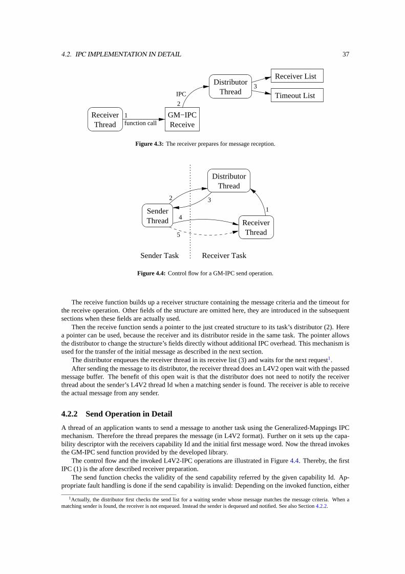
4.2. IPC IMPLEMENTATION IN DETAIL 37
Receiver List
Timeout List
DistributorThread
GM−IPCReceiveThread
Receiver
3
2
function call1
IPC
Figure 4.3: The receiver prepares for message reception.
SenderThread
DistributorThread
ThreadReceiver
1
2 3
4
5
Receiver TaskSender Task
Figure 4.4: Control flow for a GM-IPC send operation.
The receive function builds up a receiver structure containing the message criteria and the timeout forthe receive operation. Other fields of the structure are omitted here, they are introduced in the subsequentsections when these fields are actually used.
Then the receive function sends a pointer to the just created structure to its task’s distributor (2). Herea pointer can be used, because the receiver and its distributor reside in the same task. The pointer allowsthe distributor to change the structure’s fields directly without additional IPC overhead. This mechanism isused for the transfer of the initial message as described in the next section.
The distributor enqueues the receiver thread in its receive list (3) and waits for the next request1.After sending the message to its distributor, the receiver thread does an L4V2 open wait with the passed
message buffer. The benefit of this open wait is that the distributor does not need to notify the receiverthread about the sender’s L4V2 thread Id when a matching sender is found. The receiver is able to receivethe actual message from any sender.
4.2.2 Send Operation in Detail
A thread of an application wants to send a message to another task using the Generalized-Mappings IPCmechanism. Therefore the thread prepares the message (in L4V2 format). Further on it sets up the capa-bility descriptor with the receivers capability Id and the initial first message word. Now the thread invokesthe GM-IPC send function provided by the developed library.
The control flow and the invoked L4V2-IPC operations are illustrated in Figure4.4. Thereby, the firstIPC (1) is the afore described receiver preparation.
The send function checks the validity of the send capability referred by the given capability Id. Ap-propriate fault handling is done if the send capability is invalid: Depending on the invoked function, either
1Actually, the distributor first checks the send list for a waiting sender whose message matches the message criteria. When amatching sender is found, the receiver is not enqueued. Instead the sender is dequeued and notified. See also Section4.2.2.
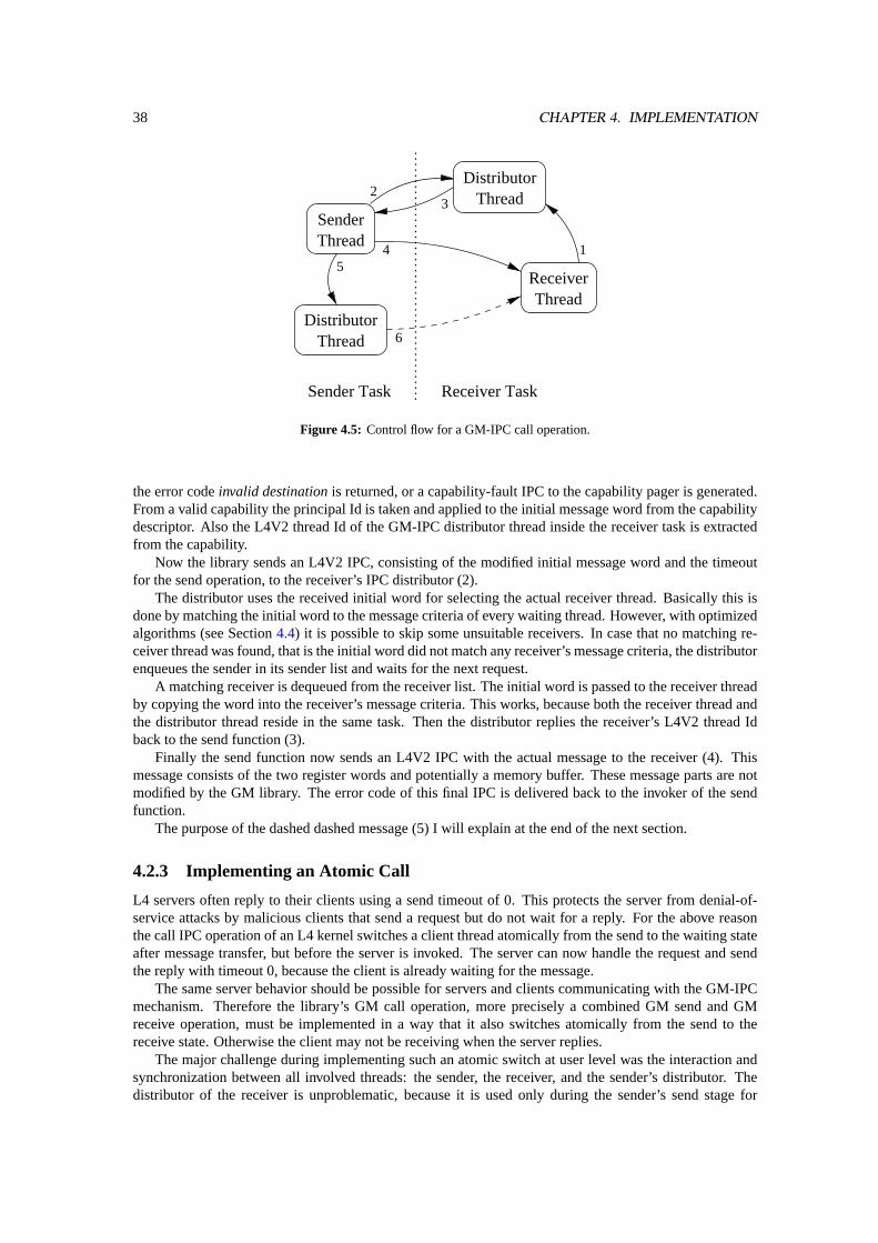
38 CHAPTER 4. IMPLEMENTATION
DistributorThread
ThreadReceiver
SenderThread
DistributorThread
15
23
4
6
Sender Task Receiver Task
Figure 4.5: Control flow for a GM-IPC call operation.
the error codeinvalid destinationis returned, or a capability-fault IPC to the capability pager is generated.From a valid capability the principal Id is taken and applied to the initial message word from the capabilitydescriptor. Also the L4V2 thread Id of the GM-IPC distributor thread inside the receiver task is extractedfrom the capability.
Now the library sends an L4V2 IPC, consisting of the modified initial message word and the timeoutfor the send operation, to the receiver’s IPC distributor (2).
The distributor uses the received initial word for selecting the actual receiver thread. Basically this isdone by matching the initial word to the message criteria of every waiting thread. However, with optimizedalgorithms (see Section4.4) it is possible to skip some unsuitable receivers. In case that no matching re-ceiver thread was found, that is the initial word did not match any receiver’s message criteria, the distributorenqueues the sender in its sender list and waits for the next request.
A matching receiver is dequeued from the receiver list. The initial word is passed to the receiver threadby copying the word into the receiver’s message criteria. This works, because both the receiver thread andthe distributor thread reside in the same task. Then the distributor replies the receiver’s L4V2 thread Idback to the send function (3).
Finally the send function now sends an L4V2 IPC with the actual message to the receiver (4). Thismessage consists of the two register words and potentially a memory buffer. These message parts are notmodified by the GM library. The error code of this final IPC is delivered back to the invoker of the sendfunction.
The purpose of the dashed dashed message (5) I will explain at the end of the next section.
4.2.3 Implementing an Atomic Call
L4 servers often reply to their clients using a send timeout of 0. This protects the server from denial-of-service attacks by malicious clients that send a request but do not wait for a reply. For the above reasonthe call IPC operation of an L4 kernel switches a client thread atomically from the send to the waiting stateafter message transfer, but before the server is invoked. The server can now handle the request and sendthe reply with timeout 0, because the client is already waiting for the message.
The same server behavior should be possible for servers and clients communicating with the GM-IPCmechanism. Therefore the library’s GM call operation, more precisely a combined GM send and GMreceive operation, must be implemented in a way that it also switches atomically from the send to thereceive state. Otherwise the client may not be receiving when the server replies.
The major challenge during implementing such an atomic switch at user level was the interaction andsynchronization between all involved threads: the sender, the receiver, and the sender’s distributor. Thedistributor of the receiver is unproblematic, because it is used only during the sender’s send stage for
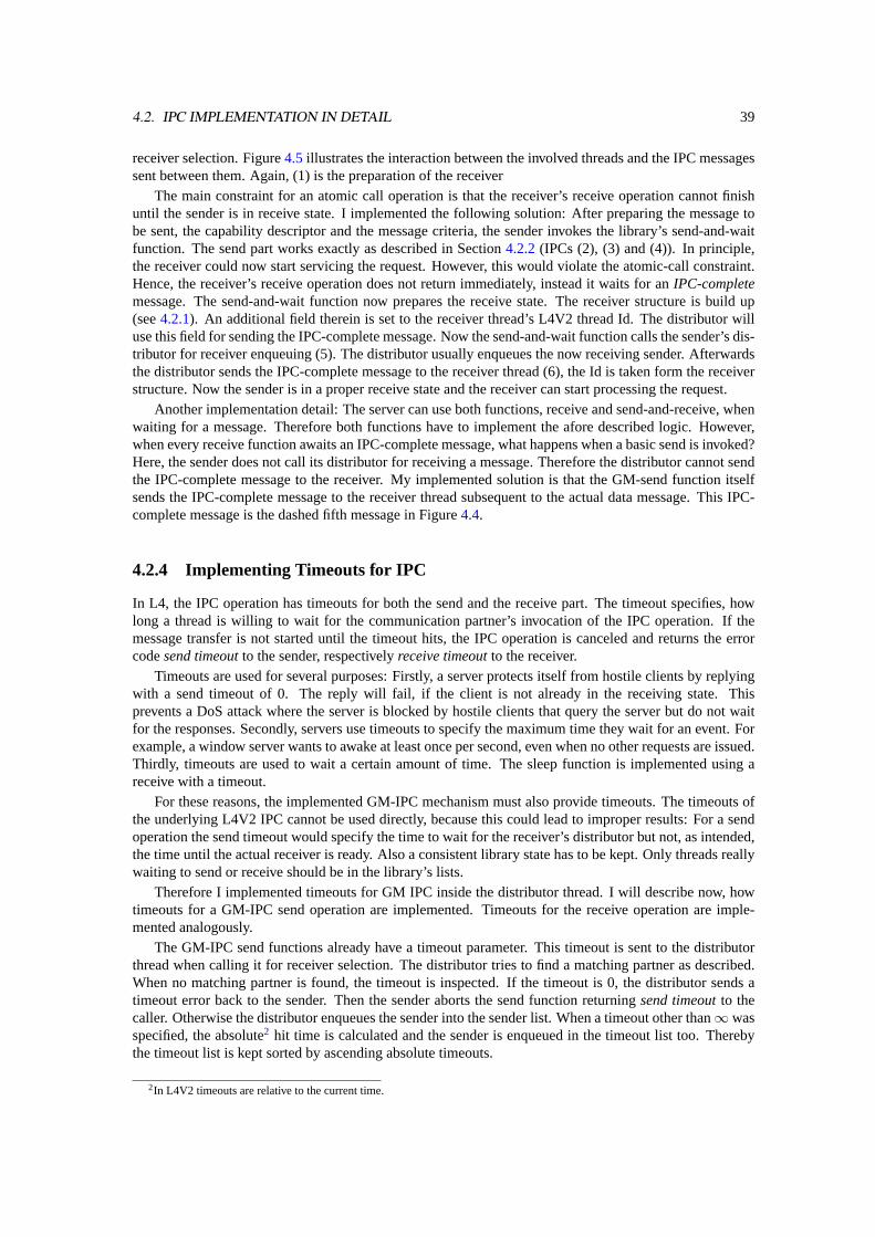
4.2. IPC IMPLEMENTATION IN DETAIL 39
receiver selection. Figure4.5illustrates the interaction between the involved threads and the IPC messagessent between them. Again, (1) is the preparation of the receiver
The main constraint for an atomic call operation is that the receiver’s receive operation cannot finishuntil the sender is in receive state. I implemented the following solution: After preparing the message tobe sent, the capability descriptor and the message criteria, the sender invokes the library’s send-and-waitfunction. The send part works exactly as described in Section4.2.2(IPCs (2), (3) and (4)). In principle,the receiver could now start servicing the request. However, this would violate the atomic-call constraint.Hence, the receiver’s receive operation does not return immediately, instead it waits for anIPC-completemessage. The send-and-wait function now prepares the receive state. The receiver structure is build up(see4.2.1). An additional field therein is set to the receiver thread’s L4V2 thread Id. The distributor willuse this field for sending the IPC-complete message. Now the send-and-wait function calls the sender’s dis-tributor for receiver enqueuing (5). The distributor usually enqueues the now receiving sender. Afterwardsthe distributor sends the IPC-complete message to the receiver thread (6), the Id is taken form the receiverstructure. Now the sender is in a proper receive state and the receiver can start processing the request.
Another implementation detail: The server can use both functions, receive and send-and-receive, whenwaiting for a message. Therefore both functions have to implement the afore described logic. However,when every receive function awaits an IPC-complete message, what happens when a basic send is invoked?Here, the sender does not call its distributor for receiving a message. Therefore the distributor cannot sendthe IPC-complete message to the receiver. My implemented solution is that the GM-send function itselfsends the IPC-complete message to the receiver thread subsequent to the actual data message. This IPC-complete message is the dashed fifth message in Figure4.4.
4.2.4 Implementing Timeouts for IPC
In L4, the IPC operation has timeouts for both the send and the receive part. The timeout specifies, howlong a thread is willing to wait for the communication partner’s invocation of the IPC operation. If themessage transfer is not started until the timeout hits, the IPC operation is canceled and returns the errorcodesend timeoutto the sender, respectivelyreceive timeoutto the receiver.
Timeouts are used for several purposes: Firstly, a server protects itself from hostile clients by replyingwith a send timeout of 0. The reply will fail, if the client is not already in the receiving state. Thisprevents a DoS attack where the server is blocked by hostile clients that query the server but do not waitfor the responses. Secondly, servers use timeouts to specify the maximum time they wait for an event. Forexample, a window server wants to awake at least once per second, even when no other requests are issued.Thirdly, timeouts are used to wait a certain amount of time. The sleep function is implemented using areceive with a timeout.
For these reasons, the implemented GM-IPC mechanism must also provide timeouts. The timeouts ofthe underlying L4V2 IPC cannot be used directly, because this could lead to improper results: For a sendoperation the send timeout would specify the time to wait for the receiver’s distributor but not, as intended,the time until the actual receiver is ready. Also a consistent library state has to be kept. Only threads reallywaiting to send or receive should be in the library’s lists.
Therefore I implemented timeouts for GM IPC inside the distributor thread. I will describe now, howtimeouts for a GM-IPC send operation are implemented. Timeouts for the receive operation are imple-mented analogously.
The GM-IPC send functions already have a timeout parameter. This timeout is sent to the distributorthread when calling it for receiver selection. The distributor tries to find a matching partner as described.When no matching partner is found, the timeout is inspected. If the timeout is 0, the distributor sends atimeout error back to the sender. Then the sender aborts the send function returningsend timeoutto thecaller. Otherwise the distributor enqueues the sender into the sender list. When a timeout other than∞ wasspecified, the absolute2 hit time is calculated and the sender is enqueued in the timeout list too. Therebythe timeout list is kept sorted by ascending absolute timeouts.
2In L4V2 timeouts are relative to the current time.
40 CHAPTER 4. IMPLEMENTATION
The distributor implements timeouts by waiting for new requests with a receive timeout of 10 ms.There is nothing special with 10 ms, it is just a tradeoff between accuracy and additional load due totimeout handling. However the used Fiasco kernel seems to handle timeouts also every 10 ms.
When the distributor receives a message, or when its receive timeout hits, the first timeout is checked.If it is less than the current time, timeout handling is done. Thereby the timed out thread is dequeued fromthe timeout list and from the sender list, respectively the receiver list. Then a timeout error is sent back tothis thread. These steps are repeated until the first timeout is later than the current time or, of course, thetimeout list is empty. After timeout handling the distributor processes the received request, if there wasone.
4.2.5 Capability Mapping and Unmapping
The mapping of capabilities during GM IPC is done purely inside the library. In analogy to memorymappings the sender specifies a capability flexpage it wishes to send inside its message. The receiverspecifies a receive window where it is willing to receive capabilities. After the receiver selection thecapabilities from the sender’s flexpage mapped to the receiver according to the rules from [2] if the flexpageand the receive window are of different size. Afterwards the L4V2 message transfer is started as describedin Section4.2.2. During this message transfer the sender’s capability-flexpage descriptor is transfered asraw data by the underlying L4V2 kernel. The receiver can use the received capability-flexpage descriptorto determine which capabilities have been mapped into its capability space.
Unmapping of send capabilities, thus the revocation of communication channels, is a key functionalityof Generalized Mappings. In today’s L4, unmap is a system call. Since the library capsulates the handlingand mapping of send capabilities, it has to provide also an appropriate unmap functionality for these capa-bilities. Like the GM-IPC functions, the library-provided unmap takes the same parameters as the standardunmap: the flexpage to unmap and an unmap mask. When the flexpage is a send-capability flexpage, thelibrary handles the unmap internally, i. e. traversing the mapping database of each capability within theflexpage and unmap the capability from all tasks it was mapped to. As expected, unmapping of send capa-bilities works transitively as well. Other flexpage types, ordinary memory or IO flexpages, are forwardedto the L4 kernel’s unmap system call. However, thecomplete spaceis special cased by the library’s unmap:It first unmaps all send capabilities. Then the kernel’s unmap is invoked, which unmaps all memory pages.
4.2.6 Capability Fault Handling
Another important functionality the library provides is the handling of capability faults. Capability faultsoccur when a capability Id referring to an invalid capability is used for an IPC operation. The two types3
of fault handling are to send a capability-fault IPC to the pager or to abort the faulting IPC. For the lattercase the library provides an extra send function which returns an error code. The standard send functiondoes the first type of error handling.
To handle capability faults a task needs a capability pager. Because of the different handling of memoryfaults — they are detected by the L4 kernel and handled using L4V2 IPC — and send-capability faults,which are detected by the library and handled using GM IPC, the L4V2 pager of the faulting thread cannotbe used as capability pager. Thus an extra pager for handling send-capability faults is needed. In theprototype the capability pager is per task. I decided so after analyzing the usage of the per thread memorypager. The memory pager was only changed when a region manager is used. The region manager thenforwards the page fault to the appropriate pager. However, the same for capabilities can be achieved bysupplying a wrapper around the error returning GM-IPC send functions.
The program can set the send-capability pager using a library provided function which takes a capa-bility Id and the initial first message word as parameters. The mechanisms described in Section3.2.7are not feasible, because the prototype does only IPC management. For task and thread management thefunctionality of the underlying L4 kernel is used.
So when the GM send operation detects an invalid capability, it generates a capability fault messageand sends that message to the task’s capability pager. After the pager replied an appropriate capability
3For discussion refer to Section4.2.6.
4.3. MATCHING REQUIREMENTS 41
mapping, the failed send operation is restarted. If the pager capability is invalid as well, the faulting threadis shut down.
4.3 Matching Requirements
In Generalized Mappings IPC the receiver thread of a message sent to a task is selected based on themessage content. A thread waiting for a message specifies a pattern, the message criteria, on its waitoperation. An incoming message must match the specified criteria to be delivered to that thread. Refer toSection3.2.6for a detailed discussion.
The basic algorithm to find receiver thread for an incoming message is to compare the message withthe message criteria from all waiting threads. When the comparison succeeds for a thread that thread is avalid candidate for message reception. Since the message criteria is a variable-length bit string, which iscompared with the beginning of the message and the comparison ignores the tailing message bits, this typeof comparison is called aprefix match.
The main challenge during receiver selection is to find the thread with the best matching messagecriteria from all valid candidates. That is to find the thread which specified the longest matching messagecriteria. So algorithms used in GM receiver selection must be able to search the longest matching messagecriteria (the longest matching prefix) for an incoming message.
A common example for longest prefix matching is the routing decision for packets in IP networks:For an incoming packet a router selects the next router, thus the outgoing interface, based on the packet’sdestination. From its routing table the router searches the entry with the longest matching prefix to thedesired destination.
In contrast to prefix matching, many search algorithms performexact matching. Here two keys arecompared and the comparison only succeeds when both keys are equal and of the same length. For exampleconsider the password for a computer login: To gain access, the typed password must be exactly the same— char-by-char — as the stored password. When you type more or less characters, the login will be denied.
The problem with exact matching for GM receiver selection is that in many cases the specified messagecriteria will shorter than the incoming message. So exact matching will not find a valid receiver candidate.Cutting the message to the criteria length can prevent the failed comparison. However, cutting once to afixed length does not solve the original problem because threads inside a task can specify different criterialengths.
4.4 Receiver Selection Algorithms
This section describes possible algorithms for receiver selection. The benefits and the problems when usingthe algorithms for prefix matching are discussed. Concrete numbers for the implemented algorithms arepresented in Chapter5.
For search time complexity the following notation is used:n is the number of waiting threads.w is themaximum length of the message criteria the threads specified for their wait operation.
4.4.1 Linear List Search
The first implemented algorithm for receiver selection is a linear search through all waiting threads. Ichose the linear search, because I did not expect any implementation difficulties and I wanted to run mytest applications. So I got a working GM IPC path without sophisticated receiver selection.
Linear search works directly on the distributor’s client-thread descriptors of my library. The descriptorsof all waiting threads are chained into a linear list. On an incoming message the whole list is traversed tofind a suitable receiver. The receiver thread with the longest matching prefix is chosen as the messagerecipient and dequeued from the list. When multiple receivers specified the same prefix and length (e. g.,they implement a thread pool) the first one found is used.
42 CHAPTER 4. IMPLEMENTATION
In principle, linear search can be used with any other matching algorithm, because the matching algo-rithm is applied to the message specification of every receiving thread. However, in this thesis only prefixmatching is used.
The time needed for finding the actual receiver thread for an incoming message depends on the numberof waiting threads. So the time consumed for receiver selection isO(n). Inserting a new receiver threadinto the list is done inO(1), because new receivers are always enqueued at the beginning of the list. Theenqueuing does not have an influence on the search operation, because all receiver-thread descriptors aresearched through thereby.
4.4.2 Binary Trees and Tries
Binary Tree
A binary tree is a data structure that can be used for storing data keys and finding them later. The treeconsists of nodes, each node stores a data key and two pointers to the left and the right subtree. A searchfor a key starts at the root node of the tree. The search key is compared with the node’s data key. Whenthe keys are equal, the search was successful. Otherwise, depending on whether the search key is greateror less than the node key, the search continues on the right or on the left subtree. Searching the binary treeterminates either on a successful comparison — the key was found — or when branching to a non-existingsubtree. In the latter case the searched key was not found in the tree.
The shape of a binary tree depends on the insertion order of the keys. Therefore binary trees can becomeunbalanced. In the worst case the tree degenerates to a linear list. This is especially a problem, because theworst case can occur frequently in practice, for example when the keys are inserted in sorted order.
The search complexity of a perfect binary isO(log n). However, unbalanced trees need more time tosearch a key, up to the worst case ofO(n).
Another problem of a binary tree is that both the insert and the search operation use an exact matchbetween the search (or insert) key and the node key. In contrast, the receiver selection for GM IPC has tofind the thread with the longest matching message criteria. Padding a short message criteria with zero bits(or any other known bit combination) does not work, because the respective bits of the incoming messageare not known a priory. The padding bits likely have a wrong value, so the expanded criteria will not matchthe incoming message.
Binary Trie
Both problems, the unpredictable shape and the applicability of prefix matching, can be addressed witha binary trie. Let me first describe the basic concept of a binary trie4. Thereafter I will discuss prefixmatching and further optimizations.
Like the binary tree a binary trie consists of nodes with a data key and two subtree pointers. Thebranching decision, however, is not determined by comparing the keys themselves. Instead the individualbits of the search key are used. A search starts with the search key’s most significant bit at the root node.The left branch is taken on a0 bit, the right branch on a1 bit. Trie traversal continues with the next bit.The basic search scheme is considered successful, when the bits of the search key run out and the data keyof the reached node is valid. Otherwise the searched key was not found in the trie.
The basic search scheme does exact matching, as a binary tree too. Fortunately, the trie can be adaptedfor prefix matching: When the finally reached node from the basic search scheme does not contain a validdata key, the search backtracks, potentially up to the trie root. Only when no valid node is found on thewalked path, the search terminates unsuccessful. Otherwise the backtracking ensures that the data key withthe longest matching prefix is found. A more efficient implementation omits backtracking by rememberingthe last visited valid node during tree traversal. The remembered node can be returned directly when thefinally reached node has no valid data key.
The shape of a binary trie depends on the inserted keys but not on their insertion order, because for thebranching decision the individual key bits are used and not complete key value. So the search time for akey in a binary trie does not depend on the number of keys nor their insertion order. Only the key length
4The termtrie is derived from retrieval [6].
4.4. RECEIVER SELECTION ALGORITHMS 43
is important: The search complexity of a binary trie isO(w). This also holds for searching the longestmatching prefix.
Path Compression
Unlike binary trees, binary tries do not become unbalanced. However, the tries are often still too deep: Thedepth of a leaf node is equal to the length of its key in bits.
Long chains of nodes with only one child node occur frequently in tries. Such a chain without branchesindicates that all keys following the chain have an identical prefix. The idea of path compression is toconvert these chains into a single node. Thereby the skipped branches, thus the skipped key bits fromthe original chain, are recorded in that node. The resulting path compressed trie is less deep than thecorresponding binary trie except in the rare occurring worst case.
Path compressed tries are also calledprefix tries. An example for a path compressed trie is the PATRI-CIA trie [23] used in text searching algorithms and the 4.3BSD routing table [26].
With prefix free keys a PATRICIA trie withn stored keys hasn leaf nodes with the keys, called externalnodes, andn − 1 internal nodes. Each internal node has exactly two child nodes. The average depth of aPATRICIA trie with m nodes islog m, while the average depth of the binary trie is the average key length.
When the keys are not prefix free, the external nodes are not necessarily leaf nodes. They can alsooccur within the trie. In contrast to internal nodes, external nodes within the trie can have only one childnode. The number of internal nodes in such a trie is at mostn− 1. The average trie depth remainslog m.
The rarely occurring worst case for a path compressed trie is when the keys have increasing length andshorter keys are prefixes of longer keys. Then the resulting trie is a sorted linear list.
Implementation
In my library I did not implement pure binary tries for matching the incoming message with the receiver’smessage criteria because of the expected chains without branches. Nodes in such chains require additionalstorage. They also increase the search time for a receiver because of the needed bit tests per node and alsodue to the increased cache working set: The more nodes have to be tested the more cache is needed andtherefore more application cache lines are destroyed.
A prefix trie does not suffer on these two problems, therefore I implemented it. I did not use differentnode layouts for internal and external trie nodes, because the given message criteria of one thread can bea prefix on another thread’s message criteria. Then an external node exists inside the trie and not only atthe leafs. Another reason is that I do not have to test for different node types during trie traversal whensearching or inserting a key. Also, on insertion of a new waiting thread whose specified message criteria isthe same as the key of the reached internal node, there is no need to convert the internal node to an externalnode.
Thus, a trie node consists at least of two pointers to the left and to right subtrie, a pointer to a thread listwith all threads waiting for the reached prefix and the bit number to test for the next branching decision.The problems that arise now are how to represent the skipped bits and how to test them. One solution wouldbe to store the skipped bits inside the trie node as a variable-length bit string and compare them before eachbranch. However, variable-length bit strings are often inconvenient to handle. Trie implementations used invirtual memory management for translating virtual addresses into physical addresses delay the comparisonof the skipped bits until a leaf node is reached [27]. The entire key is stored in the leaf node or in a tableoutside the trie, for example in a frame table. After reaching a leaf node the entire key is compared withthe stored key at once. When the keys are not equal, some of the skipped bits were different and no validaddress translation exists.
Unfortunately, the described algorithm cannot be used for GM, because of its assumption: The algo-rithm assumes a prefix free trie which is true for memory. This assumption does not hold for the messagecriteria of waiting threads in GM IPC, where one thread can specify a longer criteria starting with exactlythe same bits that are another thread’s shorter criteria. In such a case for an incoming message the bestmatching criteria has to be found for IPC handshake and message delivery.
In my prototype a message criteria has at most 32 bits. So I decided to include two additional fieldsinto my trie nodes: the entire node key and a mask for the valid key bits. The mask is precomputed from
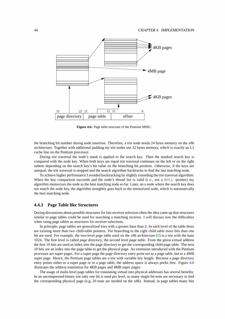
44 CHAPTER 4. IMPLEMENTATION
page directory page table offset
4KB pages
4MB page
4KB pages
21 1131 01222
Figure 4.6: Page table structure of the Pentium MMU.
the branching bit number during node insertion. Therefore, a trie node needs 24 bytes memory on the x86architecture. Together with additional padding my trie nodes use 32 bytes memory, which is exactly an L1cache line on the Pentium processor.
During trie traversal the node’s mask is applied to the search key. Then the masked search key iscompared with the node key. When both keys are equal trie traversal continues on the left or on the rightsubtrie depending on the search key’s bit value on the branching bit position. Otherwise, if the keys areunequal, the trie traversal is stopped and the search algorithm backtracks to find the last matching node.
To achieve higher performance I avoided backtracking by slightly extending the trie traversal algorithm:When the key comparison succeeds and the node’s thread list is valid (i. e., not aNULL -pointer) myalgorithm memorizes the node as the best matching node so far. Later, on a node where the search key doesnot match the node key, the algorithm straightly goes back to the memorized node, which is automaticallythe best matching node.
4.4.3 Page Table like Structures
During discussions about possible structures for fast receiver selection often the idea came up that structuressimilar to page tables could be used for searching a matching receiver. I will discuss now the difficultieswhen using page tables as structures for receiver selections.
In principle, page tables are generalized tries with a greater base than 2: In each level of the table thereare existing more than two child-table pointers. For branching to the right child table more bits than onebit are used. For example, the two-level page table used on the x86 architecture [8] is a trie with the base1024. The first level is calledpage directory, the second levelpage table. From the given virtual addressthe first 10 bits are used as index into the page directory to get the corresponding child page table. The next10 bits are an index into the page table to get the physical page. An extension introduced with the Pentiumprocessor are super pages. For a super page the page directory entry point not to a page table, but to a 4MBsuper page. Hence, the Pentium page tables are a trie with variable key length. Because a page directoryentry points either to a super page or to a page table, the address space is always prefix free. Figure4.6illustrates the address translation for 4KB pages and 4MB super pages.
The usage of multi-level page tables for translating virtual into physical addresses has several benefits:In an uncompressed binary trie only one bit is used per level, so many single bit tests are necessary to findthe corresponding physical page (e.g, 20 tests are needed on the x86). Instead, in page tables many bits

4.4. RECEIVER SELECTION ALGORITHMS 45
are used to find the next table level (10 bits on x86). So the number of memory accesses and the actualtranslation time is reduced.
Like a trie, multilevel page tables allow holes in an address space: When no pages are allocated insidea large region (on x86 a 4MB region aligned to 4MB) no page table is needed for that region, the entireregion is marked invalid in the page directory. This mechanism helps to save memory for page tablesby allocation only the actually needed page tables. So smaller tables offer the opportunity of saving tablememory because they can support smaller holes. However, smaller tables per level means more table levels,increasing the translation time. Therefore the table size is a tradeoff between the memory consumption forthe page table and the translation time.
For larger address spaces, e. g. the virtual address space on 64-bit architectures, more page-table levelsor larger tables per level are needed. Assuming a page size of 4K, a table entry needs 8 Byte (52 bits pageaddress and 12 bits for permission, attributes, etc.), so a 4K frame holds 512 Entries. A multi-level pagetable will have 6 levels for address translation. Such a deep table is inefficient for most tasks, because onlysmall portions of the address space are actually used. So tables on intermediate levels often contain onlyone valid entry.
Guarded Page Tables(GPT) [16] skip these intermediate levels by using a guard representing theskipped address bits. Effectively, skipping bits during translation is applying path compression to thepage table. Hence, GPTs are generalized PATRICIA tries with a radix greater than 2. Like in tries, pathcompression helps to save memory and translation time. Another benefit from GPTs is the support of dif-ferent page sizes withsize = 2n. Thereby, like hierachical page tables, guarded page tables support prefixfree keys. Furthermore, with GPTs the size of a page table in a table level can vary depending on the pagedistribution in the corresponding memory region. Larger tables are used for densely populated regions,smaller ones for sparsely populated ones. In both cases the skipped bits help to reduce the table depth.
L4 implementations for the MIPS [3] and the Alpha processor use GPTs for address translation.
Page Tables or GPT for Receiver Selection?
Page tables and guarded page tables used for address translation are designed for prefix free search keys.Prefix free means that inside a memory region covered by a super page (e. g., a 4MB region aligned to 4MBon x86) no translation for a 4K page can exist. This property is enforced by hardware (x86) or by software(L4 on MIPS [3, 27]). Both implementations use a single bit test to distinguish whether the translationreached a valid super page or a next level page table.
However, the message criteria used for selecting a receiver thread in the GM-IPC mechanism has notthe property of prefix free keys. Rather, the longest key from all keys matching the incoming message issearched. So a table entry can contain both a valid key with a link to a waiting thread and a link to a nextlevel table for possible longer keys. Hence, unmodified standard page tables cannot be used because theyonly support one link type per entry at a time. Another problem I described already with tries is also presenton page-table like structures: Since the key space is not prefix free, the search algorithm has to backtrackwhen no matching key is found on deeper table levels. To save search time backtracking can be optimizedas in my implemented trie (Section4.4.2).
The main problem I see when using page table like structures for receiver selection is the arbitrarylength of the message criteria, especially in combination with the prefix keys. With standard page tables itis difficult to support arbitrary key length because a fixed number of bits is used as an index into the table.However, a waiting thread of a GM task can specify a fewer number of bits as its message criteria. Theobvious solution of using less index bits, therefore using smaller tables, leads to a binary trie.
One solution to support any possible length is a table layout as shown in Figure4.7. Here a table levelconsists of several tables: The first table provides the linkage to the next table level. The firstk bits fromthe key are used as index into this table (in the examplek is 4). For each possible lengthl smaller thanka table for threads specifyingl significant bits as message criteria exists. In the example there are tablesfor threads with three, two, and one significant bits containing eight, four, and two entries. You shouldnote the difference between entries of different tables marked with the same number: The first entry of the3-bit table means000 , i. e. three zero bits, while the first entry of the one-bit table stands for0 , one zerobit. The final one-entry “table” is a bit special, it is used for threads waiting for all messages regarding thereached table. For the top-level table this field is used for threads invoking an open wait. In deeper levels
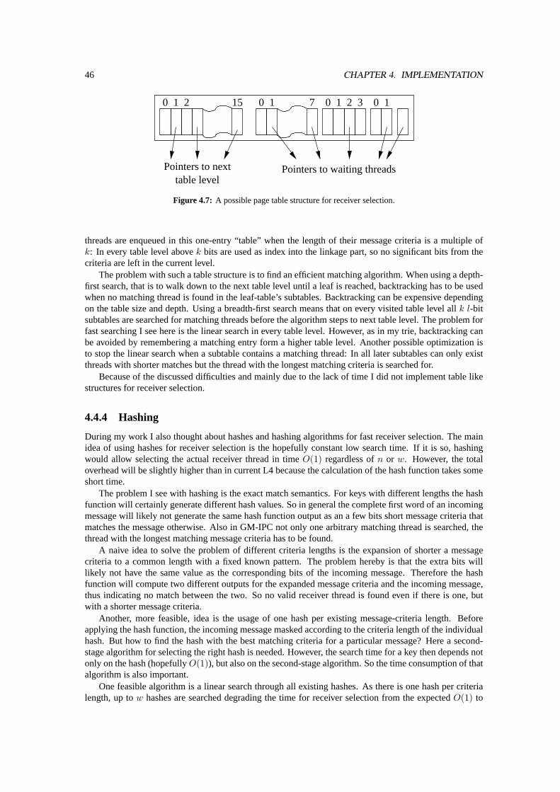
46 CHAPTER 4. IMPLEMENTATION
0 1
Pointers to waiting threads
0 1 7 0 1 32
Pointers to nexttable level
0 1 152
Figure 4.7: A possible page table structure for receiver selection.
threads are enqueued in this one-entry “table” when the length of their message criteria is a multiple ofk: In every table level abovek bits are used as index into the linkage part, so no significant bits from thecriteria are left in the current level.
The problem with such a table structure is to find an efficient matching algorithm. When using a depth-first search, that is to walk down to the next table level until a leaf is reached, backtracking has to be usedwhen no matching thread is found in the leaf-table’s subtables. Backtracking can be expensive dependingon the table size and depth. Using a breadth-first search means that on every visited table level allk l-bitsubtables are searched for matching threads before the algorithm steps to next table level. The problem forfast searching I see here is the linear search in every table level. However, as in my trie, backtracking canbe avoided by remembering a matching entry form a higher table level. Another possible optimization isto stop the linear search when a subtable contains a matching thread: In all later subtables can only existthreads with shorter matches but the thread with the longest matching criteria is searched for.
Because of the discussed difficulties and mainly due to the lack of time I did not implement table likestructures for receiver selection.
4.4.4 Hashing
During my work I also thought about hashes and hashing algorithms for fast receiver selection. The mainidea of using hashes for receiver selection is the hopefully constant low search time. If it is so, hashingwould allow selecting the actual receiver thread in timeO(1) regardless ofn or w. However, the totaloverhead will be slightly higher than in current L4 because the calculation of the hash function takes someshort time.
The problem I see with hashing is the exact match semantics. For keys with different lengths the hashfunction will certainly generate different hash values. So in general the complete first word of an incomingmessage will likely not generate the same hash function output as an a few bits short message criteria thatmatches the message otherwise. Also in GM-IPC not only one arbitrary matching thread is searched, thethread with the longest matching message criteria has to be found.
A naive idea to solve the problem of different criteria lengths is the expansion of shorter a messagecriteria to a common length with a fixed known pattern. The problem hereby is that the extra bits willlikely not have the same value as the corresponding bits of the incoming message. Therefore the hashfunction will compute two different outputs for the expanded message criteria and the incoming message,thus indicating no match between the two. So no valid receiver thread is found even if there is one, butwith a shorter message criteria.
Another, more feasible, idea is the usage of one hash per existing message-criteria length. Beforeapplying the hash function, the incoming message masked according to the criteria length of the individualhash. But how to find the hash with the best matching criteria for a particular message? Here a second-stage algorithm for selecting the right hash is needed. However, the search time for a key then depends notonly on the hash (hopefullyO(1)), but also on the second-stage algorithm. So the time consumption of thatalgorithm is also important.
One feasible algorithm is a linear search through all existing hashes. As there is one hash per criterialength, up tow hashes are searched degrading the time for receiver selection from the expectedO(1) to

4.4. RECEIVER SELECTION ALGORITHMS 47
O(w). When searching the hashes in ascending criteria length order, always all hashes must be searchedthrough because the last hash with the most specific message criteria might contain a matching receiverthread. Like in my trie, a hash containing a match is remembered until a hash with a longer criteria hasa matching thread inside. So it is guaranteed that the thread with the longest matching message criteria isselected for message reception.
In contrast, searching the hashes in descending length order can stop on the first hash containing amatch. All unsearched hashes can contain only less specific matches with a shorter message criteria. Sodescending search is faster than ascending search except when only the shortest length hash contains amatch or no match is found at all.
So in the worst case, searching through all hashes, hashing is slower than a trie (alsoO(w)) because thehash calculation is more complex than the trie’s bit test for branching. For the average case an estimationis more difficult. Hashes may be faster, depending on the actual implementation, when only few differentcriteria lengths each with a lot of threads with different criteria exist. Then a trie will have many branchestoward the leafs consuming many bit tests while only a few hash calculations are necessary. Descendingsearch will also be faster than a trie when the wide majority of incoming messages is for waiting threadsthat specify a long message criteria. Here the first searched hash will contain a valid receiver thread — nofurther hashes are searched.
However, for the described difficulties with hashes, the unclear search time, and due to the limited timefor this thesis I did not implement hashes for receiver selection.

48 CHAPTER 4. IMPLEMENTATION
Chapter 5
Evaluation
In this chapter the implemented Generalized Mappings IPC mechanism will be evaluated quantitatively.However, detailed end-to-end IPC benchmarks, for instance using the standard ping-pong benchmark, arerather useless because the prototype implementation is a user-land wrapper library: The library layer intro-duces additional latency in terms of the total consumed time and also in terms of cache usage. ThereforeI created a set of microbenchmarks to measure the important parts from the GM-IPC path. With the mi-crobenchmarks I can avoid the library’s additional IPC overhead.
Evaluation Environment
All microbenchmarks were done on an Intel Pentium processor (P54C, CPUID 5:2:B) with 133 Mhz onan Intel i430 FX chipset based mainboard (Asus P54TP4). The processor has an 8 KB 2-way associativedata cache with a cache-line size of 32 bytes. The data TLB has 64 entries for 4 KB pages and is 4-wayassociative. These TLBs are flushed on an address space switch. Further on, the board is equipped with64 MB RAM and 256 KB unified 2nd level cache. The network card, an Intel Ethernet Pro 100, is onlyused for booting the machine.
The microbenchmarks ran on the Fiasco microkernel extended by a system call for flushing the cachesfrom user level. Besides the benchmarks the standard components from the L4Env [12], the name server,the log server and the dataspace manager, were running. All used software was compiled with gcc 2.95.4.
All times presented in the next sections are in processor cycles. They where measured using the proces-sor’s internal timestamp counter, which is read using therdtsc instruction [9] — excluding the overheadof that instruction.
Experiments
I created two microbenchmarks that cover the two fundamental parts of the Generalized-Mapping IPC path:the capability usage for allowing and authenticating IPC, and the receiver selection for finding the actualreceiver thread. The first part, the capability access, I account to the sender side. The second part, receiverselection, clearly depends on the concrete receiver thread structure, so it is accounted to the receiver side.Both parts together build the IPC handshake.
The first microbenchmark measured the additional costs when using a capability for authorizing anIPC. As my library is a prototypic design the capability access and check is written in C and not highlyoptimized. Therefore a measurement of that path would result in a relatively high numbers indicating slowcapability checking and thus much overhead. So I decided to implement an optimized path for benchmark-ing the capability testing overhead in assembly language like it will be used in an in-kernel implementation.The measurements of that path and a discussion follows in Section5.1.
With the second microbenchmark the performance of the implemented algorithms for receiver selectionis quantified. Here I created a multi-threaded server task and a single-threaded client. The server threadsare waiting for messages. Thereby each server thread uses a unique message criteria. The different thread’smessage criteria have a length of 24 bits and are distributed uniformly among that 24-bit address space.
49
50 CHAPTER 5. EVALUATION
The client is in a loop. Within each iteration it calls a randomly chosen server thread. Inside my libraryI instrumented the receiver selection to measure the time it takes until the receiver thread is definitely found.The consumed time is averaged over 10000 client calls. For the implemented receiver selection algorithmsthe numbers are presented in Section5.2followed by a discussion.
5.1 Performance on the Sender Side
When a task sends an IPC message a kernel with the new Generalized-Mappings IPC mechanism has toexecute the following steps:
1. calculate the kernel representation from the sender specified send capability to access the actualcapability
2. check the validity of the send capability
3. apply the principal Id from the capability to the message
4. figure out the destination task to start the receiver selection in that task.
The send capabilities are stored in a large array indexed by the capability Id. A naive implementation woulduse0...CAP_MAX as capability Id. To access the actual capability, the capability Id is multiplied withthe kernel’s capability size and the base of the array is added. However, multiply operations are quite slowcompared to other arithmetic operations on most processors. Also a bounds check withCAP_MAXhas tobe done to avoid using arbitrary memory regions as send capabilities.
Liedtke showed in [15] that a large array in the virtual address space is feasible for fast addressing ofthread control blocks in L4 when using a clever encoding scheme for thread Id’s. The same mechanismcan be used for addressing the send capabilities: To calculate the address of the capability’s kernel repre-sentation the user supplied capability Id is masked and the base offset of the send-capability array is added.Consequently only two basic arithmetic operations are necessary: anand for the mask application and anadd with the base offset. Both the mask and the base offset are constant.
The next step, the capability validity check, consists of two operations, one test operation and a condi-tional branch. The test operation checks the valid field of the capability structure. When the test fails, thebranch is taken and capability error handling takes place. In the common case, the capability is valid, thebranch is not taken. Since modern microprocessors assume conditional forward branches as not taken andfetch the instructions immediately following the branch into the pipeline, the common case is not sloweddown significantly.
In the third step the principal Id is applied to the message. Thereby bits used by the PID are maskedout from the message. Then the PID is added to the message. Both fields, the mask and the PID come fromthe internal capability representation. The mask is calculated during the map operation and stored in thecapability for performance reasons during capability usage. So PID application are also two operations.
Now let me consider two cases: The fast case occurs when all accessed data resides in the cache andthe TLB contains a valid address translation for the used send capability. In the slower second case thecaches and the TLBs are empty.
In the optimal fast case all described operations can be executed at maximum speed. Since a validaddress translation exists in the TLB an all data (the whole capability structure) resides in the cache noadditional cycles besides the normal instruction execution are needed. In the microbenchmark I measured6 cycles for the optimum case.
In the slower case the first two operations, the calculation of the actual capability structure, runs at thesame speed as the fast case because no memory is referenced. However, for the validity check the capability,and thus the memory, has to be accessed. No valid address translation for the capability structure can befound in the TLB so the hardware1 starts to walk through the page table to find a valid translation forupdating the TLB. As the memory address used by the capability cannot be found in the cache, additionalcycles are needed to access the real memory. My send capabilities are using 32 bytes memory, which is
1The x86 architecture has a built-in hardware page table walker.
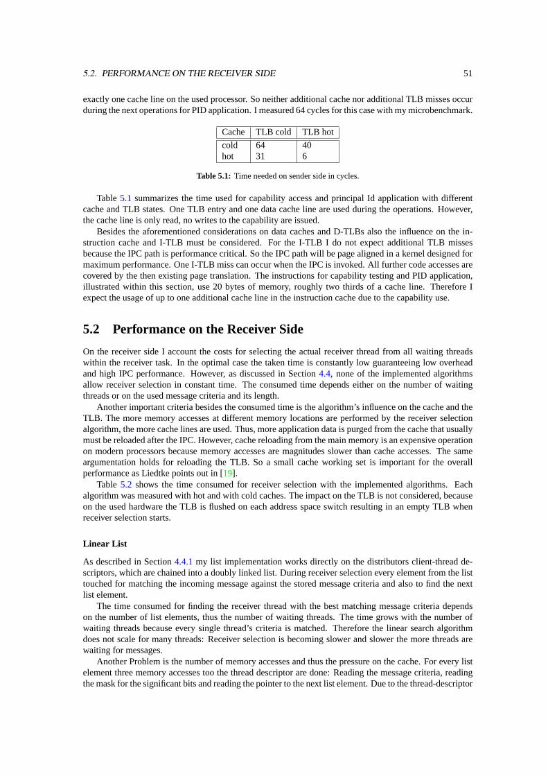
5.2. PERFORMANCE ON THE RECEIVER SIDE 51
exactly one cache line on the used processor. So neither additional cache nor additional TLB misses occurduring the next operations for PID application. I measured 64 cycles for this case with my microbenchmark.
Cache TLB cold TLB hot
cold 64 40hot 31 6
Table 5.1: Time needed on sender side in cycles.
Table5.1 summarizes the time used for capability access and principal Id application with differentcache and TLB states. One TLB entry and one data cache line are used during the operations. However,the cache line is only read, no writes to the capability are issued.
Besides the aforementioned considerations on data caches and D-TLBs also the influence on the in-struction cache and I-TLB must be considered. For the I-TLB I do not expect additional TLB missesbecause the IPC path is performance critical. So the IPC path will be page aligned in a kernel designed formaximum performance. One I-TLB miss can occur when the IPC is invoked. All further code accesses arecovered by the then existing page translation. The instructions for capability testing and PID application,illustrated within this section, use 20 bytes of memory, roughly two thirds of a cache line. Therefore Iexpect the usage of up to one additional cache line in the instruction cache due to the capability use.
5.2 Performance on the Receiver Side
On the receiver side I account the costs for selecting the actual receiver thread from all waiting threadswithin the receiver task. In the optimal case the taken time is constantly low guaranteeing low overheadand high IPC performance. However, as discussed in Section4.4, none of the implemented algorithmsallow receiver selection in constant time. The consumed time depends either on the number of waitingthreads or on the used message criteria and its length.
Another important criteria besides the consumed time is the algorithm’s influence on the cache and theTLB. The more memory accesses at different memory locations are performed by the receiver selectionalgorithm, the more cache lines are used. Thus, more application data is purged from the cache that usuallymust be reloaded after the IPC. However, cache reloading from the main memory is an expensive operationon modern processors because memory accesses are magnitudes slower than cache accesses. The sameargumentation holds for reloading the TLB. So a small cache working set is important for the overallperformance as Liedtke points out in [19].
Table 5.2 shows the time consumed for receiver selection with the implemented algorithms. Eachalgorithm was measured with hot and with cold caches. The impact on the TLB is not considered, becauseon the used hardware the TLB is flushed on each address space switch resulting in an empty TLB whenreceiver selection starts.
Linear List
As described in Section4.4.1my list implementation works directly on the distributors client-thread de-scriptors, which are chained into a doubly linked list. During receiver selection every element from the listtouched for matching the incoming message against the stored message criteria and also to find the nextlist element.
The time consumed for finding the receiver thread with the best matching message criteria dependson the number of list elements, thus the number of waiting threads. The time grows with the number ofwaiting threads because every single thread’s criteria is matched. Therefore the linear search algorithmdoes not scale for many threads: Receiver selection is becoming slower and slower the more threads arewaiting for messages.
Another Problem is the number of memory accesses and thus the pressure on the cache. For every listelement three memory accesses too the thread descriptor are done: Reading the message criteria, readingthe mask for the significant bits and reading the pointer to the next list element. Due to the thread-descriptor
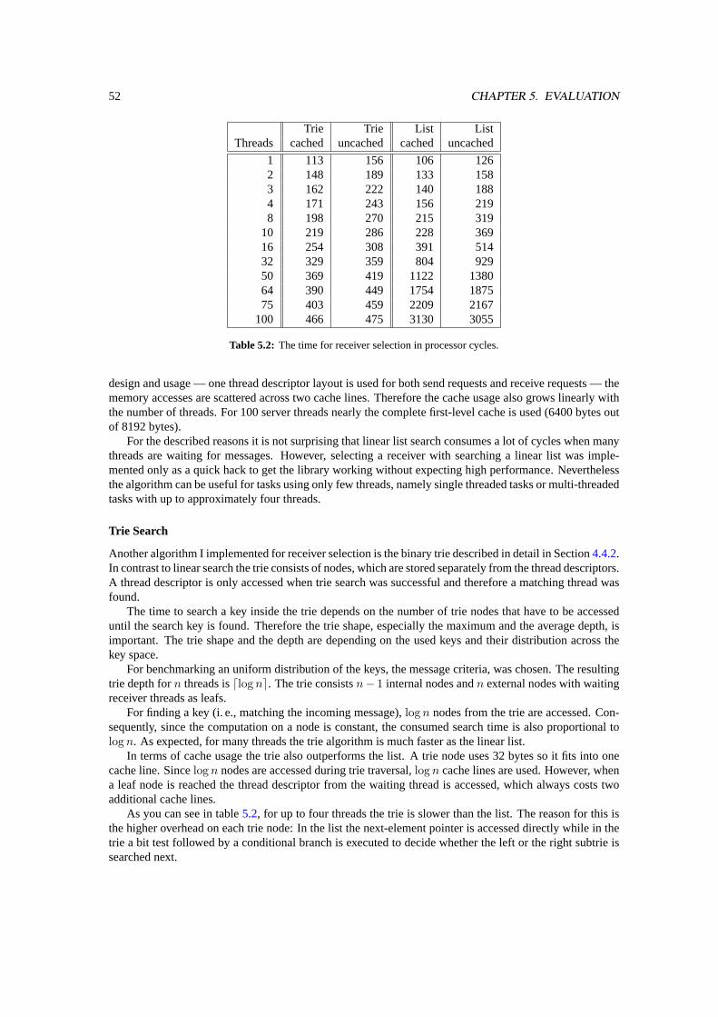
52 CHAPTER 5. EVALUATION
Trie Trie List ListThreads cached uncached cached uncached
1 113 156 106 1262 148 189 133 1583 162 222 140 1884 171 243 156 2198 198 270 215 319
10 219 286 228 36916 254 308 391 51432 329 359 804 92950 369 419 1122 138064 390 449 1754 187575 403 459 2209 2167
100 466 475 3130 3055
Table 5.2: The time for receiver selection in processor cycles.
design and usage — one thread descriptor layout is used for both send requests and receive requests — thememory accesses are scattered across two cache lines. Therefore the cache usage also grows linearly withthe number of threads. For 100 server threads nearly the complete first-level cache is used (6400 bytes outof 8192 bytes).
For the described reasons it is not surprising that linear list search consumes a lot of cycles when manythreads are waiting for messages. However, selecting a receiver with searching a linear list was imple-mented only as a quick hack to get the library working without expecting high performance. Neverthelessthe algorithm can be useful for tasks using only few threads, namely single threaded tasks or multi-threadedtasks with up to approximately four threads.
Trie Search
Another algorithm I implemented for receiver selection is the binary trie described in detail in Section4.4.2.In contrast to linear search the trie consists of nodes, which are stored separately from the thread descriptors.A thread descriptor is only accessed when trie search was successful and therefore a matching thread wasfound.
The time to search a key inside the trie depends on the number of trie nodes that have to be accesseduntil the search key is found. Therefore the trie shape, especially the maximum and the average depth, isimportant. The trie shape and the depth are depending on the used keys and their distribution across thekey space.
For benchmarking an uniform distribution of the keys, the message criteria, was chosen. The resultingtrie depth forn threads isdlog ne. The trie consistsn− 1 internal nodes andn external nodes with waitingreceiver threads as leafs.
For finding a key (i. e., matching the incoming message),log n nodes from the trie are accessed. Con-sequently, since the computation on a node is constant, the consumed search time is also proportional tolog n. As expected, for many threads the trie algorithm is much faster as the linear list.
In terms of cache usage the trie also outperforms the list. A trie node uses 32 bytes so it fits into onecache line. Sincelog n nodes are accessed during trie traversal,log n cache lines are used. However, whena leaf node is reached the thread descriptor from the waiting thread is accessed, which always costs twoadditional cache lines.
As you can see in table5.2, for up to four threads the trie is slower than the list. The reason for this isthe higher overhead on each trie node: In the list the next-element pointer is accessed directly while in thetrie a bit test followed by a conditional branch is executed to decide whether the left or the right subtrie issearched next.
Chapter 6
Conclusion
In this thesis I developed a capability-based communication control and corresponding IPC mechanism forthe L4 microkernel. The requirements for the IPC mechanism are presented in Section3.1. A prototypicalimplementation proved the feasibility both from a performance and functional point of view.
The Generalized-Mappings communication mechanism uses explicit communication channels betweentasks. These channels are authorized with task-send capabilities introduced in Section3.2. Possession ofsuch a capability allows its owner to send messages to the task the capability refers to. A task withoutsend capabilities to a particular task cannot send messages to that task. Therefore, send capabilities are aneffective way to restrict the ability of a task to communicate to other tasks.
In Section5.1 I showed that the overhead introduced into the time-critical IPC path causes by theadditional indirection when using capabilities is fairly low. In the optimal case this indirection and theneeded calculation costs only 6 additional cycles. In comparison with the total IPC costs of 215 cyclesthese additionally incurred costs are negligible. This case, however, assumes that all needed data resides inthe cache and a valid address translation exist in the TLB. In the worst case one additional cache miss andone additional TLB miss occur in the IPC path when accessing the capability, for discussion see Section5.1.
I also discussed how I extended the mechanisms L4 provides for memory management at user level, themapping and unmapping of pages, to apply them to send capabilities. Thereby the map operation allowsfor the delegation of rights: A task can map its send capabilities to another task. Afterwards both tasks cansend messages to the receiver task specified in the capability. In contrast to other capability based systems,such as Amoeba or EROS, our approach provides an effective way for selective revocation of capabilities:the unmap operation. Unmap enables a task to revoke capabilities it previously mapped to other tasks.Afterwards these tasks cannot use the unmapped capability for sending messages anymore.
The developed IPC mechanism provides local names for both senders and receivers. Using local namesenable several advantages over globally unique names: They allow late binding from names to actualcommunication partners. The name of the communication partner remains the same when the partner isexchanged, for example when a server task is restarted due to an update.
The flexibility of this new communication mechanism I showed in Section3.3. First, I showed how anintercepting task, for example a debugger or a filter, is inserted into an existing communication channel.Thereby the insertion of the interceptor can be transparent to the involved tasks. Second, I emulated thecurrent L4 approach with globally unique thread Id’s on top of local names and capability authenticatedcommunication to show backwards compatibility.
With Generalized Mappings IPC the receiver thread of a incoming message is chosen by the kernelbased on the message content. On a receive operation, a thread specifies a pattern, the message criteria,an incoming message must match to be delivered to that thread. The kernel matches the message to thespecified message criteria and delivers the message to the waiting thread if the criteria matches the message.This mechanism, however, slows down the IPC performance because in the timeframe of this thesis nomatching algorithm could be found that has a constant low selection time regardless of the number ofreceiver threads. The consumed time of all algorithms discussed in Section4.4 depends either on theconcrete number of threads in the receiver task, or on the length of the message criteria. It remains an
53
54 CHAPTER 6. CONCLUSION
open question, whether there exist matching algorithms for selecting the receiver thread in constant time,or whether another mechanism for receiver selection has to be found.
6.1 Future Work
In-Kernel Implementation
The Generalized Mappings IPC mechanism should be implemented inside a L4 kernel in future. An in-kernel implementation does not suffer from the additional library overhead. Also security requirementsregarding the communication restrictions can be met in an in-kernel implementation.

Appendix A
Appendix
A.1 Glossary
Task Is a collection of resources. Often a task is used for accounting purposes. A task is also a protectiondomain.
Thread An activity inside a task, an abstraction of a CPU. A thread can use the resources its task owns.
Memory The virtual address space of a task.
IPC Communication between threads.
MessageA message is sent from one thread to another with the IPC Operation. A message contains adirect part, indirect strings (optional) and flexmappings (optional). The direct part and the strings aresimply copied from the sender to the receiver. Flexmappings are inserted into the appropriate tables(e. g., memory mappings into the page tables, send capabilities into the send-capability table).
Task-Send Capability The right to send a message to a task. Send capabilities are objects provided andprotected by the kernel. User applications use them for invoking IPC and can map them to othertasks. The send capability refers to the task actually receiving message. The receiver cannot bealtered by the task possessing the capability. However, more bits can be appended to the kernelprotected PID of the capability during the map operation.
Open Wait A thread waits for any incoming message.
Group Wait In contrast to open wait, a thread waits for a given message criteria. Incoming messages tothe task that match the given criteria are delivered to this thread.
Closed Wait As in group wait, a thread specifies a message criteria the incoming message must match.However, in contrast to group wait, the specified message criteria can only be sent by one sendertask1.
Principal Id The kernel authenticated part of a message. The PID is stored inside the kernel as part of atask-send capability. It is not accessible by the capability-possessing task.
Message Criteria The receiver specifies a message criteria for messages it is willing to receive. An in-coming message that matches the criteria is delivered to the waiting receiver.
Flexmapping A generalized flexpage. Resources (e. g., memory pages, or task-send capabilities) are dis-tributed between tasks with messages containing one or more flexmappings.
Resource Fault a generalized page fault. The kernel sets up a fault IPC to the pager on behalf of thefaulting thread.
1provided that the senders pager does not try to impersonate
55
56 APPENDIX A. APPENDIX
Pager A resource-fault message is sent to the pager of the faulting thread. The pager resolves the fault andmaps the requested resource.
→ B A send capability that can be used to send messages to taskB.
A → B TaskA owns a send capability to taskB.
A.2 Acronyms
ABI application binary interface
ACL access control list
API application programmers interface
D-TLB translation look-aside buffer for data accesses
DoS denial of service
GM generalized mappings
GM IPC generalized mappings IPC
I-TLB translation look-aside buffer for instruction fetches
IPC inter process communication
PID principal Id
TCB trusted computing base
TLB translation lookaside buffer
VM virtual memory
Bibliography
[1] M. J. Accetta, R. V Baron, W. Bolosky, D. B. Golub, R. F. Rashid, A. Tevanian, and M. W. Young.Mach: A new kernel foundation for unix development. InUSENIX Summer Conference, pages 93–113, Atlanta, GA, June 1986.
[2] A. Au and G. Heiser. L4 user manual. UNSW-CSE-TR 9801, University of New South Wales, Schoolof Computer Science, Sydney, Australia, March 1999.
[3] K. Elphinstone. Virtual memory in a 64-bit micro-kernel, 1999.
[4] The Fiasco microkernel. URL:http://os.inf.tu-dresden.de/fiasco/ .
[5] Fiasco-UX, the Fiasco User-Mode Port. URL:http://os.inf.tu-dresden.de/fiasco/ux/ .
[6] Edward Fredkin. Trie memory.Communications of the ACM, 3(9):490–499, 1960.
[7] Michael Hohmuth. The Fiasco kernel: System architecture. Technical Report TUD-FI02-06-Juli-2002, TU Dresden, 2002.
[8] Intel Corp. Pentium Processor User’s Manual, Volume 3: Architecture and Programming Manual,1993.
[9] Intel Corp. Intel Architecture Software Developer’s Manual, Volume 2: Instruction Set Reference,1999.
[10] Trent Jaeger, Kevin Elphinstone, Jochen Liedtke, Vsevolod Panteleenko, and Yoonho Park. Flexibleaccess control using IPC redirection. In7th Workshop on Hot Topics in Operating Systems (HotOS),Rio Rico, Arizona, March 1999.
[11] Trent Jaeger, Jonathon E. Tidswell, Alain Gefflaut, Yoonho Park, Kevin J. Elphinstone, and JochenLiedtke. Synchronous IPC over transparent monitors. InProceedings of the 9th workshop on ACMSIGOPS European workshop, pages 189–194, Kolding, Denmark, 2000. ACM.
[12] L4 Environment Concept Paper. Available from URL:http://os.inf.tu-dresden.de/l4env/doc/l4env-concept/l4env.ps , June 2003.
[13] Butler W. Lampson. Protection. InProceedings of the 5th Princeton Conference on Information Sci-ences and Systems, pages 437–443, Princeton, March 1971. Reprinted inOperating Systems Review,8(1):18–24, January 1974.
[14] J. Liedtke. Clans & chiefs. In12. GI/ITG-Fachtagung Architektur von Rechensystemen, pages 294–305, Kiel, March 1992. Springer.
[15] J. Liedtke. Improving IPC by kernel design. InProceedings of the 14th ACM Symposium on OperatingSystem Principles (SOSP), pages 175–188, Asheville, NC, December 1993.
[16] J. Liedtke. Page table structures for fine-grain virtual memory.IEEE Technical Committee on Com-puter Architecture Newsletter, pages xx–xx, xx 1994. also published as Arbeitspapier der GMD No.872, German National Research Center for Computer Science (GMD), Sankt Augustin, 1993.
57
58 BIBLIOGRAPHY
[17] J. Liedtke. Onµ-kernel construction. InProceedings of the 15th ACM Symposium on OperatingSystem Principles (SOSP), pages 237–250, Copper Mountain Resort, CO, December 1995.
[18] J. Liedtke. L4 reference manual (486, Pentium, PPro). Arbeitspapiere der GMD No. 1021, GMD— German National Research Center for Information Technology, Sankt Augustin, September 1996.Also Research Report RC 20549, IBM T. J. Watson Research Center, Yorktown Heights, NY, Septem-ber 1996.
[19] J. Liedtke.µ-kernels must and can be small. In5th International Workshop on Object Orientation inOperating Systems (IWOOOS), pages 152–155, Seattle, WA, October 1996.
[20] J. Liedtke. Toward realµ-kernels.Communications of the ACM, 39(9):70–77, September 1996.
[21] Jochen Liedtke. L4 version X in a nutshell. Unpublished manuscript, August 1999.
[22] Linux website. URL:http://www.linux.org .
[23] Donald R. Morrison. PATRICIA—practical algorithm to retrieve information coded in alphanumeric.Journal of the ACM, 15(4):514–534, 1968.
[24] R. M. Needham and R. D.H. Walker. The cambridge CAP computer and its protection system. InProceedings of the 6th ACM symposium on Operating systems principles (SOSP), pages 1–10. ACMPress, 1977.
[25] J. S. Shapiro.EROS: A Capability System. PhD thesis, University of Pennsylvania, April 1999.
[26] Keith Sklower. A tree-based packet routing table for berkeley UNIX. InUSENIX Winter Conference,pages 93–104, Dallas, TX, January 1991.
[27] Cristan Szmajda. A new virtual memory implementation for L4/MIPS.
[28] A. S. Tanenbaum, S. J. Mullender, and R. van Renesse. Using sparse capabilities in a distributedoperating system. In6th International Conference on Distributed Computing Systems, pages 558–563, Cambridge, MA, May 1986.
[29] Andrew S. Tanenbaum, Robbert van Renesse, Hans van Staveren, Gregory J. Sharp, and Sape J.Mullender. Experiences with the amoeba distributed operating system.Communications of the ACM,33(12):46–63, 1990.
[30] Version X.0 specification of the L4 API. URL:http://www.l4ka.org/documentation/files/l4-86-x0.pdf .
[31] Microsoft windows website. URL:http://www.microsoft.com/windows .
[32] W. Wulf, E. Cohen, W. Corwin, A. Jones, R. Levin, C. Pierson, and F. Pollack. Hydra: The kernel ofa multiprocessing operating system.Communications of the ACM, 17(6):337–345, July 1974.