Embed Size (px)
Citation preview
Available online at www.sciencedirect.com
ScienceDirect Procedia Engineering 00 (2014) 000–000
www.elsevier.com/locate/procedia
1877-7058 © 2014 The Authors. Published by Elsevier Ltd. Peer-review under responsibility of organizing committee of the 23rd International Meshing Roundtable (IMR23).
23rd International Meshing Roundtable (IMR23)
Generating Unstructured Nuclear Reactor Core Meshes in Parallel
Rajeev Jain*a, Timothy J. Tautgesb aArgonne National Laboratory, Chicago, IL, 60516, U.S.A.
bCD-Adapco, Austin, TX, 78747, U.S.A
Abstract
Recent advances in supercomputers and parallel solver techniques have enabled users to run large simulations problems using millions of processors. Techniques for multi-physics nuclear reactor core simulations are under active development in several countries. Most of these techniques require large unstructured meshes that can be hard to generate in a standalone desktop computers, due to high memory requirements, limited processing power and other complexities. We have previously reported on a hierarchical lattice-based approach for generating reactor core meshes. Here, we describe efforts to exploit coarse-grained parallelism during reactor assembly and reactor core mesh generation processes. We highlight several reactor core examples including VHTR (Very High Temperature Reactor), a Full Core model for model of Korean MONJU reactor, a ¼ Pressurized Water Reactor core, the fast reactor Experimental Breeder Reactor-II core with XX09 assembly and an Advanced Breeder Test Reactor core. The times required to generate large mesh models, along with speedups obtained from running these problems in parallel, are reported. A graphical user interface to the tools described here has also been developed. © 2014 The Authors. Published by Elsevier Ltd. Peer-review under responsibility of organizing committee of the 23rd International Meshing Roundtable (IMR23)
Keywords: nuclear reactor core mesh, parallel mesh generation, meshkit, rgg, assygen, coregen
1. Introduction
Mesh generation is a challenging field of science that has made rapid advancement over the years. New discretization techniques, improvements in computer hardware and robust solver methods have aided to the research in this field. Fully detailed multi-physics reactor core analysis can be performed on hundreds of thousands of CPU cores, and such simulations require large meshes that are often hard or impossible to generate on a standalone desktop computer.
Nuclear reactor core consists of uranium fuel rods, instrumentation rods, control rods, ducts, coolant, grid spacers, load pads, restraint ring systems and other supporting structure. Although these core models are quasi-2.5-dimensional, modeling of inter-assembly gaps forming the whole core model from the component assemblies can

2 Rajeev Jain/ Procedia Engineering 00 (2014) 000–000
get very cumbersome and difficult to manage using scripts or traditional meshing packages. It can take a few days to create a fully detailed reactor core model with a few million of elements. Moreover, constructing these models on typical desktop computers can require large runtimes, and for large models may not succeed at all due to memory constraints. Analysts require a parallel modeling tool that can generate large core models in a few hours and also simplify the overall process of generation of reactor core models.
This paper is an extension to our previous paper [1] that describes a lattice-based approach to simplify and automate the creation of reactor assembly and core meshes. The primary contribution of this paper is parallel version of assembly and core generation process and also a GUI for our tools. During the creation of models for various large multi-physics simulations, we show that our approach significantly reduces the time taken to create core models and in several cases demonstrates superlinear speedups. The remainder of this paper is organized as follows: Section 2 gives the background, which includes MeshKit and Reactor Geometry (and mesh) Generator (RGG) tools AssyGen and CoreGen [1] developed in our previous paper. Section 3 gives the parallel algorithm. Section 4 highlights the open source RGG Nuclear application developed by Kitware Inc. Section 5 describes example core models created using these tools, along with performance data. Section 6 gives discussions and future work. Section 7 is conclusions.
2. Background
This section summarizes three major components that are essential to the algorithms presented in section 3 of this paper. Two major tools AssyGen and CoreGen are a part of MeshKit mesh generation library. Subsections below briefly describe MeshKit, AssyGen and CoreGen.
2.1. MeshKit
MeshKit is an open-source mesh generation library under development at Argonne National Laboratory, providing efficient algorithms for mesh copy/move/merge, extrude, and other algorithms [2]. It is implemented in C++, and provides a traditional C++-based API for interactions with other codes. A Python interface is also provided, for interactive access to the library. MeshKit relies on geometry and mesh libraries developed as part of the Interoperable Tools for Advanced Petascale Simulations (ITAPS) project. The Common Geometry Module (CGM) [3] provides functions for constructing, modifying, and querying geometric models in solid model-based and other formats. While CGM can evaluate geometry from several underlying geometry engines, this work relies mostly on ACIS [4], with an Open.Cascade-based [5] version also supported. Finite-element mesh and mesh-related data are stored in the Mesh-Oriented datABase (MOAB) [6]. MOAB provides query, construction, and modification of finite-element meshes, plus polygons and polyhedra. Various options are available for writing and visualizing the final meshes produced by meshing algorithms. MOAB uses an HDF5 based file format, which can be visualized using a ParaView plugin that is implemented by the MOAB library. The VisIt visualization tool can also be configured and built with MOAB to provide a similar import capability.
MeshKit’s design philosophy is two-fold: it provides a collection of meshing algorithms for use in real meshing problems, along with other tools commonly needed to support mesh generation (coordination of BREP-based meshing process, mesh smoothing, etc.); and it serves as a platform in which to perform mesh generation algorithm research. MeshKit also supports the connection of external meshing algorithms to the rest of the library, enabling the use of proprietary or experimental algorithms. MeshKit uses a graph-based process for specifying the overall meshing approach, with graph nodes representing meshing and other operations, and graph edges as dependencies between those operations. Provision is made for operations to construct other operation nodes automatically, for the purpose of meeting input constraints by specific algorithms; in this way, users need only focus on the graph nodes for which specific input is needed. Executing the meshing process consists of traversing the graph twice; the “setup” phase starts at the leaf node and proceeds in reverse up the graph, with graph nodes create any upstream nodes on which they depend then the “execute” phase traverses from the root and proceeds in the forward direction, executing nodes in graph-topological traversal order.
The graph based approach supports the traditional BREP-driven meshing process which usually proceeds by meshing BREP entities in increasing topological dimension, starting with vertices, then edges, and so on. However,

Rajeev Jain/ Procedia Engineering 00 (2014) 000–000 3
a graph-based process also enables meshing tasks not possible using a strict BREP-based approach. First, not every meshing process needs or has a geometric model representing the entire domain to be meshed. The best example of this is the Reactor Geometry (&mesh) Generator (RGG) tool, where individual assembly types have geometric models but are then copy/moved into a lattice of assembly models forming a reactor core (Section 2.2 and 2.3 describes the AssyGen and CoreGen tools in RGG respectively). Second, a meshing procedure may not involve only a once-through meshing of each BREP entity; again, RGG is a good example of this, where the first part of the process involves meshing BREP models, but the last step involves copy/moving mesh subsets into a larger core lattice (See Figure 2). Finally, the procedure-driven approach to meshing represented by most CAD-based meshing tools fails to capture the parallelism and dependency structure that can be found in most meshing problems (including BREP-based ones); representing and exploiting this richer structure provides more flexibility while still being applicable to BREP-based problems.
2.2. AssyGen
AssyGen is the first step of the three-step core mesh creation process implemented in RGG. AssyGen reads an input file describing a reactor assembly lattice and generates an ACIS or OCC –based geometry file, along with a template script for generating a mesh for the assembly using the CUBIT meshing toolkit [9]. The second step is meshing, where the user may choose to perform meshing using the CUBIT mesh script generated by AssyGen or using meshing algorithms in MeshKit. For the ‘core mesh’ shown in Fig. 2, AssyGen was run twice to create ‘Assembly Mesh1’ and ‘Assembly Mesh 2’. There are several features supported by AssyGen, such as axial numbering material and boundary conditions, sectioning, rotation, information about location of pins etc. These have been described in our previous paper [1].
2.3. CoreGen
The CoreGen tool reads an input file describing the reactor core arrangement and generates the reactor core mesh or geometry from its component assemblies. CoreGen uses CopyMesh, ExtrudeMesh, CopyGeom and MergeMesh algorithms in MeshKit. Fig. 2 shows the two assembly meshes and an interstice mesh file that form a 19-assembly reactor core. A makefile is generated by CoreGen to automate this process. Details about overall core meshing parameter specification, boundary creation, creation of a 2D-core followed by extrusion, extrude/expand/copy sets for meta data propagation to the final model are detailed in our previous paper on RGG [1]. The parallel CoreGen algorithm described in Fig. 3 is based on the core shown in Fig. 2.
Fig 2. 19 assembly core model formed using 3 mesh files and an input file describing the arrangement.

4 Rajeev Jain/ Procedia Engineering 00 (2014) 000–000
3. Parallelism Approach
Parallelizing this process not only allows faster turnaround times for large reactor core simulations, but also improves the workflow eliminating user error that sometimes occurs due to long generation times. Section 3.1 talks about parallel AssyGen and meshing algorithms, while Section 3.2 details parallel CoreGen and its component algorithms.
3.1. Parallel AssyGen and Meshing Generation
This section describes two steps of the RGG process, first, geometry creation using AssyGen and then meshing of the assembly created by AssyGen. There can be several thousands of different geometric regions in a single reactor assembly if you consider the materials and axially varying properties of the assembly. There is scope for parallelization of AssyGen: wherein each processor creates a region based on the location of the pin it obtains from the master processor. The problem with this possible approach is that the subtraction of regions from the outermost duct is a serial process. Due to unavailability of parallel subtraction of geometry from components, this feature hasn’t been developed.
A parallel meshing algorithm that partitions geometry created by AssyGen and meshes these chunks in different processors to finally create the assembly mesh is under development in MeshKit.
Once all the assembly and core input files are created, the CoreGen program is invoked to generate a makefile (see Fig. 2) that automates the whole process from geometry creation using AssyGen input files to the final core mesh file creation. This makefile can be invoked in parallel using the “-j” option of the “make” command to run geometry creation and mesh generation of individual assemblies in different CPU cores. Thus, while the creation of individual assembly geometry and meshing individual assemblies is not parallel, the generation of all assemblies needed for a given core is parallelized, using the basic parallel execution facilities of standard make process. Since complicated reactor cores often use more then ten different assembly types there is substantial speedup in this part of the RGG process.
3.2. Parallel CoreGen
Hundreds of assembly meshes along with interstices meshes such as grid-spacers, restraint rings etc. form a complete reactor core mesh. These models can be very large and can run up to several billion of mesh elements. Generation of such models in serial is a very time consuming process. The parallel CoreGen algorithm can be listed in seven steps:
1. On each processor: read CoreGen input file, parse, and determine assembly copies assigned to this processor
based on a round-robin distribution. 2. Locally read assembly meshes for assemblies determined in step 1. 3. Perform assembly copy/move operations assigned to this processor. 4. Perform local merge of on-processor mesh. 5. Perform parallel merge of mesh between processors. 6. Parallel expand/extrude/copy set (Metadata) handling. 7. Save output mesh.
Details of steps 1, 5, 6 and 7, mentioned above are given in Section 3.2.1, 3.2.2, 3.2.3 and 3.2.4 respectively. A
graphical depiction of the 4-processor parallel CoreGen process is shown in Fig. 3. Each processor loads one assembly mesh file (See left of Fig. 3, marked ‘A’). Copy/Move task distribution can be computed independently in all processors, since it is deterministic. After each processor finishes the copy/move task for its assigned assembly instances, merging of nodes, handling of mesh metadata and saving happens in parallel, the final mesh model on the right is the whole core mesh created after running CoreGen.

Rajeev Jain/ Procedia Engineering 00 (2014) 000–000 5
Fig. 3. (a) Simple example demonstrating CoreGen input and output files. (b) (A) Copy/move task distribution among processors for the same problem in Fig. 1(A) and (B) final core-mesh with numbered assemblies are shown.
3.2.1 Copy/Move Task Distribution
During each parallel CoreGen run, master processor analyzes the workload and distributes the work to individual processors. After, loading CoreGen input file on all processors, during the task distribution phase three different cases (A, B and C) may occur as noted below. Consider nA is the total number of different assembly mesh files, np is the number of processors and nT is the total number of assemblies in the reactor core.
A. np < nA B. nA < np < nT C. np > nT
In case A, each processor loads one or more assembly mesh files and solely performs the copy/move operation
associated with that assembly for the entire core. For case B, some mesh files are loaded in multiple processors, this mesh file selection is based on the frequency or the number of occurrence of that mesh file in the core. The assembly type that appears the most number of times in the core is assigned to multiple processors in a round robin fashion. Other schemes based on the size of the mesh file and recursive frequency calculation are under development. For case C, there are more processors than available work units, so only, nT processors can take part in this parallel algorithm.
The copy/move task distribution of meshes among processors can be based on a round robin scheme or it can be based on a recursive analysis of load after each mesh file is loaded. The latter scheme leads to better load balancing of meshes faster overall completion time.
3.2.2 Parallel Merge Mesh
Executing RGG in serial requires the entire model to be represented on a single processor, which limits the overall size of the assembled mesh to what can be held in memory on a given machine. The merge mesh algorithm is based on matching mesh vertices based on geometric proximity. This algorithm is created by slightly modifying the vertex-matching algorithm described in a previous paper [7]. First, instead of merging based on global Id and partitioning the global id space over processors, the geometric bounding box of all vertices is partitioned over
6 Rajeev Jain/ Procedia Engineering 00 (2014) 000–000
processors, with each processor responsible for a distinct geometric region (plus a small epsilon layer whose thickness is twice the distance tolerance of the merge). The spatial extent covered by each processor can be computed deterministically based on the global bounding box, the number of processors, and the merge tolerance. Each processor retrieves vertices on the skin of the local mesh, and performs a local merge on those vertices. Next, for the remaining skin vertices, each processor assembles a tuple list [7] which holds the (x, y, z) position of the vertex, and the destination processor is assigned according to the processor(s) responsible for that position in space. Note also that in contrast to the serial merge, merging a vertex with another on another processor does not result in one of those vertices being deleted; rather, the parallel sharing information inherent in MOAB’s parallel mesh representation is modified to indicate that they are the same logical vertex. The actual merging is done as part of the parallel write process described in Section 3.2.4.
3.2.3 Parallel Metadata Handling
In a MOAB representation of mesh, entity sets (arbitrary groupings of entities and other sets) are used to represent material and boundary condition groupings, with tags used to indicate the purpose of a given set (e.g. MATERIAL_SET, NEUMANN_SET) and tag values identifying distinct sets of that type. Each processor makes a copy of the sets that will receive new entities on a given processor resulting from the copy/move operations preformed there. In the problem specification, sets are marked as being of three distinct types for the purposes of RGG: • EXPAND: New entities copied from an original entity will be added directly to any expand sets containing the
original entity • COPY: Any copy set containing the original entities will itself be copied, and will receive the copies of entities
according to original entity membership in the original copy set(s). • EXTRUDE: In cases where MeshKit is being used for the 2D to 3D extrusion, extrude sets containing entities of
dimension d will be given the (d+1)-dimensional entities resulting from the extrusion of the original extrude set entities.
Expand sets are used to represent material in the core mesh. Copy sets can be used to group entities making up assembly instances, i.e. to distinguish the n copies of a given assembly type in the core. Expand sets are used for modelling Neumann boundary conditions in extruded or swept models.
3.2.4 Parallel Save Mesh
The parallel save option in MOAB writes a single file containing the entire mesh, with single copies of entities and entity sets that were formerly spread or shared between multiple processors. Parallel save algorithm can be broken down in four steps: 1. Compute global mesh properties (number of entities/sets of each type, global numbering of file entities etc.). 2. Write header information (root processor only). 3. Write vertex coordinates, element connectivity for owned entities (concurrent). 4. Write vertex/element tags for owned entities (concurrent). 5. Write set membership (serial).
HDF5-based files resulting from this write process can be re-partitioned using a MOAB-based partitioning tool and used as input to simulations able to read MOAB files.

Rajeev Jain/ Procedia Engineering 00 (2014) 000–000 7
4. RGG Nuclear GUI Application
Kitware Inc. has developed a GUI for creating and visualizing new and existing AssyGen and CoreGen input files. This tool is freely available and can be downloaded from Kitware website [8]. Users can create a full core geometry or mesh models from scratch using this GUI. RGG examples available with MeshKit library can also be visualized and run to create core meshes using this application. Fig. 4 shows an example of this tool displaying the 19 assemblies from the model in Fig. 3.
Fig. 4. RGG Nuclear application launched on Mac OSX shown loading simple hex-flat-core example from RGG test directory in MeshKit.
5. Results
5.1. Very High Temperature Reactor (VHTR)
The 1/6th VHTR core model shown in Fig. 5 consists of 19.6M hexahedral elements and 20.5M mesh vertices. The size of this mesh file on disk is 2.2GB.
Fig. 5. One-sixth of a VHTR core model generated by using CoreGen (left); a closeup of assembly mesh in this model (right).

8 Rajeev Jain/ Procedia Engineering 00 (2014) 000–000
It took 10.5 minutes for AssyGen to generate the geometry, journal files and CUBIT to mesh individual assemblies. Serial CoreGen took 48 minutes to generate the core model. When using 56 processors for running CoreGen this model can be generated in less than 3 mins (2.1 mins for make with 12 processors, there are 12 assemblies that form this 58 assembly model) from scratch. It must be noted the AssyGen+CUBIT are run on 1, 4, 8 and 12 processors using –j option of makefile, the maximum number of processors is limited to 12 for this step.
Table 1 lists the AssyGen+CUBIT, copy/move, merge, parallel save, total time and the maximum memory used for various steps of the CoreGen stage, when using different number of processors. Fig. 7 shows procs vs total time graphs, where super linear speedups are observed in almost all cases, this is due to the job fitting in available memory. Mesh joining is observed to actually slow down going from one to four processors; this is probably due to the communication overhead required in the parallel algorithm. However, at larger numbers of processors, the joining time is reduced far below the serial time. As expected, the total time, time taken to save and maximum memory used by a processor decreases as the number of processors increases.
Table 1. CPU time in mins and maximum memory in GB used for 1/6th VHTR core
#Procs AssyGen+CUBIT Copy/Move Merge Save Total Memory 1 10.5 17.6 10.4 0.7 48.2 4.9 4 3.4 11.0 11.7 0.01 26.2 2.6 8 2.8 11.1 5.6 0.01 19.5 2.5
16 2.1 0.4 4.7 0.01 7.3 1.7 32 2.1 0.03 0.56 0.01 2.7 0.48 56 2.1 0.0005 0.31 0.005 2.43 0.33
Fig. 6. Time vs number of processors plot for 1/6th VHTR reactor core.
5.2. Full Core MONJU Reactor
Fig. 8 and 9 show a full core MONJU reactor which is made up of 8 different assembly types and consisting of 715 assemblies in total. AssyGen and meshing takes 5.5 minutes (serial process) to mesh the 8 different assemblies. CoreGen on 712 processors takes only 90 seconds. The total wall clock time required to generate this 101M hexahedral element model from scratch is 7 mins. The maximum memory used by a processor is only 512MB. This model cannot be run in serial, due to the problem not fitting in memory. The size of the mesh file on disk is 14GB.
-‐10 0
10 20 30 40 50 60
0 10 20 30 40 50 60
Tota
l Tim
e (m
ins)
#proc
Rajeev Jain/ Procedia Engineering 00 (2014) 000–000 9
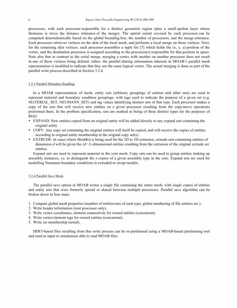
Fig. 7. Full core MONU reactor; closeup area in red rectangular region is highlighted from left to right.
Using round robin scheme to establish the copy/move work for this reactor causes the load on some processors to be larger than the available memory, we use the recursive load balanced scheme, wherein after every assembly load the loads on each processor is analyzed and then the decision on the next assembly load is made. Table 2 lists the AssyGen+CUBIT, copy/move, merge, parallel save, total time and the maximum memory used for various steps of the CoreGen stage, when using different number of processors. Fig. 8 shows procs vs total time graphs, a considerable savings in total time required to assemble the model for 512 and 712 processors. Merge time jumps up at 256 processors causing the total time to increase even more than the 16-processor run. This increase in merge and save mesh time is due to highly fragmented mesh space between processors and each processor has two or three assemblies to be copy/moved at different locations. Finding the skin and geometric proximity using bounding box approach for merging vertices (See section 3.2.2) is found to take a lot more time due to large number of inter-processors communications. At higher processor counts (512 and 712), the number of copy/move tasks per processor is one or two causing considerably less communication between processors. The overall maximum memory required by a processor decreases as the number of processors increase.
Table 2. CPU time in mins and maximum memory in 10^5KB used for MONJU core
#Procs AssyGen+CUBIT Copy/Move Merge Save Total Memory 16 5.5 163 3.8 42 207.64 42 64 5.5 61 9.01 10.4 76.7 10.4
256 5.5 291 24 24.4 321.5 3.23 512 5.5 0.49 3.85 2.33 9.99 2.33 712 5.5 0.18 2.3 1.96 7.89 1.96
Fig. 8. Time vs number of processors plot for MONJU reactor core.

10 Rajeev Jain/ Procedia Engineering 00 (2014) 000–000
5.3. 1/4th PWR
Fig. 9. shows the benchmark problem: “MOX Fuel Loaded Small PWR Core”, a detailed description can be found on the website of Nuclear Reactor Analysis and Particle Transport Lab [10]. Individual assembly geometries are created using the AssyGen tool and then the CoreGen tool is used to copy/move the assemblies and form the core geometry. In Fig. 9. A, B and C are closeup areas highlighted in red on the core model. The model consists of approximately 11k volumes, 5.2M hexes and 5.9M vertices. On a Linux desktop, the assembly geometry creation takes 8 mins and CoreGen takes 12 mins of wall clock time and uses 0.9GB of RAM. It must be noted that the maximum number of processor that can be used by CoreGen for this problem is 25, which is the total number of assemblies in this core model. Using 25 processors CoreGen takes 45 seconds and 210MB maximum memory to create the mesh, majority of the time is used in merging the nodes of between the assemblies. Using serial version of CoreGen , it takes 1.9 mins and 1.7GB of RAM. Copy/move takes 42 seconds and serial merge takes 50 seconds.
Fig. 9. 1/4th PWR benchmark geometry with closeup views A, B and C showing details of the model.
5.4. XX09 Assembly and Homegenized EBRII Core With XX09 Assembly
The instrumented XX09 assembly was used in shutdown heat removal tests (SHRTs) that demonstrated passive safety features of the EBR-II Experimental Breeder Reactor [11]. A homogenized EBRII core mesh with detailed XX09 assembly is shown in Fig. 10. The sectioned view of the core in Fig. 10 highlights the start, end of fuel rods and the conical/cylindrical coolant flow regions in XX09 assembly. This core model is formed of 217 assemblies: 216 homogenized assemblies and one XX09 assembly. The model comprises 375k hex8 elements for the neutronics mesh, 440k hex8 elements for the structural mechanics mesh, and 440k hex27 elements for the thermohydraulics mesh. The geometry for XX09 and other homogenized assemblies are generated by using AssyGen; then meshing is performed by using CUBIT; and CoreGen creates the resulting EBRII core mesh. For the six assemblies that surround the XX09 assembly, meshing is performed using AssyGen by specifying the same interval on the edge shared with the XX09 assembly (see Fig. 10 marked “Outlet”). A coarse-edge interval is assigned on all other edges. On 128 processors CoreGen takes 45 seconds to create this core model from component assemblies, the maximum memory used by a processor is only 300MB. Serially, it takes 16.8 mins and 520MB memory. In serial version, 16 mins out of the total 16.8 mins are taken by mesh merge operation.

Rajeev Jain/ Procedia Engineering 00 (2014) 000–000 11
Fig. 10. Homogenized EBRII core with XX09 assembly. Inlet, outlet, isometric, and sectioned views are zoomed in to show the fuel and other instrumentation pins in the model.
5.5. ABTR Fuel Assembly and ABTR Full Core Model With Restraint Rings and Load Pads
Fig. 11. ABTR core configuration with lines of constant logical I, J assembly regions.
The geometry-only CoreGen feature was utilized to create the outer covering with restraint rings. All the assembly geometries created by AssyGen are first copy/moved to create a geometric core model, another separate circular pin (ring) with the same axial divisions as all the other assemblies is created by using AssyGen. This pin is

12 Rajeev Jain/ Procedia Engineering 00 (2014) 000–000
subtracted from the geometric core model to create the outer core model and obtain the outer covering geometry. Meshing, material, boundary specification, and clearance gap between TLP (Top Load Pad) and ACLP (Above Core Load Pad) are modeled after this step. The clearance gap between TLP/ACLP restraint ring and load pad is modeled by shrinking the inner surfaces by clearance gap dimensions. Once the outer covering mesh is generated it is used as an interstices mesh in the CoreGen process.
CoreGen is run to create the final homogenized core model from assembly meshes and this outer covering mesh. The final mesh shown in Fig. 11 consists of 800k hex elements. The structural mechanics and thermohydraulics mesh consists of 1500 material blocks, whereas the neutronics mesh consists of 7200 material blocks. The neutronics mesh requires more material blocks along the height of the fuel pins. It takes for CoreGen 5 seconds to assemble the core using 128 processors. The maximum memory used by a processor is 110MB. Serially run time for CoreGen is 45 seconds with 280MB of memory used.
6. Discussions and Future Work
Parallel RGG tools enable creation of large and complicated reactor models. The models shown in this paper have been used in coupled multi-physics simulations. The size of the problem for multi-physics simulations has been intentionally kept coarser to understand and gain confidence in the overall simulation process. RGG is capable of creating meshes larger that the one’s shown in this paper here, however it would need geometry partitioning-based meshing algorithms to mesh the assemblies in parallel.
EBRII and ABTR core models are small and many details such as fuel and instrumentation pins are ignored to test out the physics coupling in parallel. We plan to create fully detailed models and coupling results for these models.
Work is in progress for a better load-balancing scheme, wherein meshes with larger element count are given priority during distribution of meshes among processors for load and copy/move tasks.
7. Conclusion
A very powerful and robust parallel algorithm for assembling reactor core models from its component assemblies has been developed. This approach leads to huge saving in overall time and memory requirement for such mesh generation applications.
Acknowledgements
We thank the SIGMA group at Argonne, who maintain the libraries required by this tool. This work was supported in part by the U.S. Department of Energy Office of Nuclear Energy Nuclear Energy Advanced Modeling and Simulation (NEAMS) Program; by the U.S. Department of Energy Scientific Computing Research, Office of Science; and by the U.S. Department of Energy’s Scientific Discovery through Advanced Computing program, under Contract DE-AC02-06CH11357.
References
[1] Tautges, T. J., and Jain, Rajeev. (2012). Creating geometry and mesh models for nuclear reactor core geometries using a lattice hierarchy-based approach. Engineering with Computers, 28(4), 319-329.
[2] MeshKit: http://www.mcs.anl.gov/~fathom/meshkit-docs/html/index.html [3] Tautges, T. J (2005) CGM: a geometry interface for mesh generation, analysis and other applications. Eng Comput 17:486–490. [4] Spatial website (2010) http://www.spatial.com/ [5] Open CASCADE technology website (2000–2010) http://www.opencascade.org. [6] Tautges, T. J, Meyers, R, Merkley, K, Stimpson, C, Ernst, C (2004). MOAB: A mesh-oriented database, SAND2004-1592. Sandia National
Laboratories, Albuquerque. [7] Tautges, T. J., Kraftcheck, J. A., Bertram, N., Sachdeva, V., & Magerlein, J. (2012, May). Mesh interface resolution and ghost exchange in a
parallel mesh representation. In Parallel and Distributed Processing Symposium Workshops & PhD Forum (IPDPSW), 2012 IEEE 26th International (pp. 1670-1679). IEEE.

Rajeev Jain/ Procedia Engineering 00 (2014) 000–000 13
[8] CMBNuclear download page: http://cmb.kitware.com/CMB/resources/software.html [9] Sjaardema, G.D, Tautges, T. J, Wilson, T. J, Owen, S. J, Blacker, T. D, Bohnhoff, W. J, Edwards, T. L, Hipp, J. R, Lober, R. R, and Mitchell,
S.A (1994). CUBIT mesh generation environment, users manual, vol 1. Sandia National Laboratories, Albuquerque. Detomi, D. (2002). A procedure for tetrahedral boundary layer mesh generation. Engineering with Computers, 18(1), 66-79.
[10] 1/4th PWR Benchmark Problem (2012), http://nurapt.kaist.ac.kr/benchmark/ [11] EBR-II, http://en.wikipedia.org/wiki/Experimental_Breeder_Reactor_II


![Procedia Computer Science 00 (2010) 000 000 - …...A Novel algorithm for image encryption by integrated pixel scrambling plus diffusion [IISPD] utilizing duo chaos mapping applicability](https://img.pdfslide.net/doc/110x75/5f87e4c8561695237f03c5b6/procedia-computer-science-00-2010-000-000-a-novel-algorithm-for-image-encryption.jpg)