Embed Size (px)
Citation preview

1
Generation 5Samsung Heat Pump Installation Manual

2
Heat Pump
Please register your product online at www.jouleuk.co.uk
Homeowner
Address
Contact TelContact Email
Product Product Installed (Check)
Serial Number
Installation Date
Cylinder Located in Cylinder badge
Solar Thermal Taken From Solar Controller
Solar PV One Ser. No. from String / Micro Inverter
Air Source Heat Pump
Located on External Heat Pump Badge
Integrated Heat Pump and Cylinder
Located on Cylinder Badge
Underfloor Heating Project Ref. on Supplied Schematic
Direct Gas Fire Cylinder
Located on Cylinder Badge
Installer
Address
Contact Tel.Contact Email
Joule Advance Installer
I accept the terms and conditions avilable to view on jouleuk’s website
Warranty Card

3
Table Of Contents

4
Heat Pump
COMMISSIONING
From as little as £480/€578 Inc VAT
ANNUAL SERVICING
From as little as £360/€434 Inc VAT per year
All Samsung Air Source Heat Pumps supplied by Joule must be serviced annually to val-idate the product warranty under the terms of the EUW agreement. Items that must be inspected annually to validate the warranty include, • Check outdoor fan motor and lubricate if needed• Check electrical wiring, contacts and terminals; repair as required• Check all safety components• Check compressor operation• Check indoor thermostat operation• Check defrost and heating modes (winter only)• Check for excessive noise and vibration• Check refrigerant charge• Inspect air filters• Check all safety and pressure switches• Check motor and heaters/voltage/amperes
You must ensure that if you do not choose a Joule service package then the service must be carried out annually by a suitable qualified engineer to validate the terms of the Joule EUW agreement.
Commissioning & Service

5
HEAT PUMP MAINTENANCE PACKAGE
Joule’s heat pump maintenance package entitles you to an annual maintenance visit, during which our engineer will ensure that your Samsung heat pump supplied by Joule is operating within the optimum conditions to maximise energy efficiency. Any potential issue can be dealt with by a Joule engineer. You will also be entitled to a discount on the cost of spare parts and labour.
MAINTENANCE PACKAGE RESPONSE TIMES
Joule will schedule the planned annual maintenance visit with you, usually during the off peak (Summer, Autumn) season. In the unlikely event of a fault, we will endeavour to respond as quickly as possible
HOW MUCH DOES THE HEAT PUMP MAINTENANCE PACKAGE COST?
The maintenance package costs £360/€434 inc VAT per year and is payable in ad-vance before we visit your premises. If any parts or remedial actions are required, we will provide an additional quotation for this work.
All service offers are subject to payment in advance by cleared cheque or by debit/credit card. The comprehensive service is available on a monthly direct debit plan. All service prices are inclusive of VAT
Maintenance Package

6
Heat Pump Joule 3 Year Warranty
This warranty applies only to Samsung Air Source Heat Pumps sold by a Joule Group Company and installed in Ireland or the United Kingdom. The product must be in-stalled in accordance with manufacturer’s instructions. The product must be main-tained annually by an F-GAS certified engineer and all aspects of service log to be completed annually.
1. CONTENTS OF THE WARRANTY
For a period of 3 years from commissioning or 42 months from the date of delivery to the premises of the installation or whichever is the shorter (“Warranty Period”), the homeowner (“End-User”) of the above Samsung Air Source Heat Pumps shall receive Joule’s End User Warranty (“EUW”) on the Product, subject to the two conditions (i. and ii.) set below. During the Warranty Period, Joule will repair or replace the parts and/or components of the product at Joule’s discretion so that it can ensure its con-formi-ty with Product manufacturer’s specifications. Under this EUW the replacement parts/components of the product and the labour costs thereof will be borne by Joule; pro-vided, however, that this free cost arrangement under the EUW is applied to the item(s) only falling within the scope of the Product, and does not include, for example, any pipework, connections or any other ancillary equipment connected to the Prod-uct. Joule reserves the right to inspect the Product, at the premises, before any war-ranty work is carried out. In addition, Joule will also take ownership of any replaced parts/components and/or Product, under this EUW.
i. Commissioning and activation of the product has to be installed and commissioned as per manufacturer’s instruction. It also it must be maintained annually main- tained by certified F-GAS engineer. Gas appliances must be installed and commis- sioned by a GASAFE registered engineer in UK & NI and Registered Gas Installer for Re-public of Ireland installations. After system installation the warranty registration card must be returned to Joule by email: [email protected]
ii. The Product must be maintained in accordance with the Product manufacturers’ instructions as described in the relevant manuals. In this regard, the maintenance of the Products must be carried out by a qualified/trained maintenance company and Joule reserves the right to request proof of adequate maintenance record prior to providing for any warranty work.
2. EUW ACTIVIATION
This EUW must be activated and is subject to the timely (within 30 days of com-mis-sioning) registration of the Product with Joule. Registration can be made by return-ing the completed Warranty Registration Card to [email protected]

7
3. HOW TO CLAIM UNDER THIS EUW?
The installer/maintenance company should always be the End-User’s first point of contact in the event of a breakdown or other malfunction of the Product. Only if/when confirmed that there is a fault with the Product (and not with system design or instal-la-tion), then contact should be made with Joule. It is the End-User’s responsibility to provide Joule’s representative easy and free access to the Product for warranty work to be carried out.
4. FALSE CLAIMS
Joule reserves the right to charge the End-User for any reasonable costs incurred in in-vestigating a claim where no fault has been found with the Product in the light of Prod-uct manufacturer’s specifications.
5. LIABILITY DISCLAIMER
Joule shall not be liable for any special, indirect, consequential or economic loss, how-soever arising from any defects affecting the Product or from any delay in repair-ing or replacing the Product; Joule will NOT be liable in any event in providing this EUW, for (including, but not exclusively) any fault or costs of repair resulting from:
A. Incorrect selection of the equipment, including defective design and/or application. B. Incorrect installation, inappropriate or unperformed commissioning,.C. Inappropriate maintenance or neglect, accidental and/or deliberate damage, misuse, normal wear and tear and any unauthorised alteration or repair.D. Faults or costs resulting from external sources anomalies such as lack of (or excessive) power supply, insufficient water, water/air contamination, scale forma- tion and any other elements outside Joule’s reasonable control or responsibility. E. The repair or replacement of any relevant Product consumables and the costs of any ordinary Product maintenance, and costs and/or faults resulting from any other use but the domestic purpose the Products are intended for.
6. LIMITATION OF THE WARRANTY
Under no circumstances shall any replacement parts provided and/or any warran-ty work performed lead to an extension of the Warranty Period. This EUW may be trans-ferred to a new End-User, within the remaining Warranty Period of the EUW pro-vided the Product is not removed from the original installation address. This EUW is intend-ed to assist the non-commercial and personal user of the Products for proper use in accordance with Product manufacturer’s specification, and does not affect the End-User’s statutory rights. Joule reserve the right to update this warranty (and its terms and conditions), from time to time, without notice.

8
Heat Pump • Store the manual in a safe place in order to be able to use it as reference after installation. For maximum safety installers should always carefully read the following warnings.
• Store the provided manual in a safe location with the end user after installation, and remember to hand it over to the new end user if the Heat Pump & Cylinder unit is sold or transferred.
• The Air to Water Heat Pump is compliant with the requirements of the Low Voltage Directive (2006/95/ EC), the EMC Directive (2004/108/EC) and the pressure equip-ment directive (97/23/EC).
• The manufacturers shall not be responsible for damage originating from unau thorised changes or the improper connection of electric and hydraulic lines.
• Do not use units if you see some damages on the units and recognise something untoward such as loud noise, smell or burning.
• In order to prevent electric shocks, fires or injuries, always stop the unit, disable the protection switch and contact Joule’s technical support if the unit produces smoke, if the power cable is hot or damaged, or if the unit is very noisy.
• Always remember to inspect the unit, electric connections, refrigerant tubes and protections regularly. These operations shall be performed by qualified personnel only.
• The unit contains moving parts and electrical parts which should always be kept out of the reach of children.
• Do not attempt to repair, move, alter or reinstall the unit by unauthorised personnel. These operations may cause product damage, electric shock and fires.
• Do not place containers with liquids or other objects on the unit.
• All the materials used for the manufacture and packaging of the air to water heat pump are recyclable. The packaging material and exhaust batteries of the remote controller (optional) must be disposed of in accordance with local regulations.
Pre-Installation Notes

9
• The Air to Water Heat Pump containing a refrigerant must be disposed in an authorised centre or returned to retailer as special wastes.
• Wear protective gloves to unpack, move, install, and service the unit to avoid your hands being injured by the edge of the parts. Do not touch the internal parts (water pipes, refrigerant pipes, heat exchangers, etc) while running the units. If you need to adjust and touch the units, allow sufficient time for the unit to cool and be sure to wear protective gloves.
• In case of refrigerant leakage, try to avoid contact with the refrigerant because this could result in severe wounds.
• When you install the Air-to-Water Heat Pump in a small room, you must install adequate ventilation. In the event of a refrigerant leakage, ventilation will prevent the possibility of suffocation.

10
Heat Pump
PRIMARY PIPEWORK FROM OUTDOOR UNIT TO INDOOR CYLINDER
• 5W – 28mm copper• 9kW – 28mm copper• 12kW – 28mm copper• 16kW – 32mm copper• Outdoor pipework should be fully insulated and protected from water and moisture.• If outdoor pipework is required use Joule outdoor low energy loss pipework (supplied by the meter)
ELECTICAL SUPPLY AND CABLE REQUIREMENTS
• Shielded 0.75mm 2 core cable from outdoor unit to cylinder / wiring centre location. • Shielded 0.75mm 2 core cable from wiring centre to samsung controller. • Power supply to outdoor unit to be terminated with IP67 isolator located next to the unit.• Power supply to indoor unit (MIM board) to be terminated switch fused isolator.
Outdoor unit Cable Size Breaker SizeHHSM-G500005-1 4.0 mm 16 AmpHHSM-G500009-1 4.0 mm 20 AmpHHSM-G500012-1 6.0 mm 25 AmpHHSM-G500016-1 6.0mm 32 Amp
• Power supply to the MIM units must connect to the RCD fitted inside of the MIM unit.
Control Kit Cable Size Breaker SizeMIM E03BN (5kW) 4.0 mm 20 AmpMIM E03AN 4.0 mm 20 Amp
Cable Size Number of Cores Location0.75 mm 2 Core Screened From indoor unit to outdoor unit.
F1 & F2 Comms.0.75 mm 2 Core + Earth From Zone 1 stat or Underfloor heating con-
trol centre to Indoor unit.0.75 mm 2 Core + Earth From Zone 2 stat or Underfloor heating con-
trol centre to indoor unit.0.75 mm 2 Core Screened From MIM unit to remote controller.
First Fix Notes

11
• When installing the outdoor unit take great care to install as per the detailed notes for installation locations. The Air‐to‐Water Heat Pump must have minimum clear-ance of 300mm at the rear of the unit and 1500mm at the front of the unit.
The Air-to-Water Heat Pump must not be installed in a location without these clearanc-es available.
• Condensation will form on the Air-to-Water Heat Pump. Ensure adequate provisions are put in place to prevent water forming on the ground beneath the Air-to-Water Heat Pump, resulting in a potential Health and Safety hazard.
• The Air-to-Water Heat Pump must be installed vertically and should not be tilted at an angle.
• A 5m head circulation pump must be installed on the flow pipework and a second 5m head circulation pump must be installed on the return pipework back to the Air‐to‐Water Heat Pump to ensure that minimum flow rates will be achieved (as per installation schematics). Installing a single circulation pump will not guarantee the correct flow rate. Unless using a Smart plumb cylinder or Low loss header/ Buffer vessel.
• Site visits to solve a flow rate issue due to the installation of a single pump on the pipework are not covered under EUW and as such will incur a callout charge.
• Underfloor heating pipe centres to be equal to or less than 150mm.
• Standard radiators to be a minimum twice and up to 4 times the standard radiator size.
• No mixing sets to be used on the underfloor heating manifolds.
• All manifolds must have an individual pump to help circulate and maintain flow rate.
• All radiator zones must have individual pump to help circulate and maintain flow rate.
• All zones to be controlled using 2 port valves (22mm on heating zones and 28mm on hot water zone)
• 3 port valves are not to be used.

12
Heat Pump
• Mechanical by-pass valve to be installed after pump on flow but before any zone valves.
• All underfloor heating circuits to be controlled from the run signal from the third party underfloor wiring centre.
• All radiator zones to be controlled from 3rd party time clock and stat.
• Hot water cylinder is controlled by the Samsung service controller.
• End user interacts with 3rd party controls only. It is the installers responsibility to ensure that attached designs are followed to achieve this or if a uniquely designed system is being installed the designer must allow for the 3rd party controls facility.
• Underfloor heating circuits are controlled by room stats.
• Use of time clocks to turn off underfloor heating circuits is not recommended.
• Room stats in underfloor heating circuits should not be turned off but set back to a lower temperature using appropriate heating setback control for periods of unoccupied use.
• The flow switch must be installed in horizontal pipework. Allow a minimum of 150 mm horizontal pipework on each side of the flow switch.
• Air is the most prevalent cause of restricted flow in the system. Make sure that all pipework can easily be purged of air and that all air is removed from the system prior to starting the unit. Site visits to solve a flow rate issue due to the presence of air are not covered under EUW and as such will incur a callout charge.

13
WHEN INSTALLING 1 OUTDOOR UNIT
When the air outlet is opposite the wall.
When the air outlet is to-wards the wall.
When 3 sides of the outdoor unit are blocked by the wall.
The upper part of the outdoor unit and the air
outlet is towards the wall.
The upper part of the outdoor unit and the air
outlet is opposite the walll.
When front and rear side of the outdoor unit is towards
the wall.
300m
m o
r m
ore
1500
mm
or m
ore
300mm or more
600mm or more
300m
m o
r m
ore
600mm or more
1500
mm
or m
ore
300mm or more
600m
m o
r m
ore
1500mm or more
300m
m o
r m
ore
Locating The Outdoor Unit

14
Heat Pump
The units must be installed according to distances declared, in order to permit accessibility from each side, either to
guarantee correct operation of maintenance or repairing products.
The unit’s parts must be reachable and ovable completely under safety condition.
When the air outlet is toward the wall.
When 3 sides of the outdoor unit are blocked by the wall.
When front and rear side of the outdoor unit is towards the wall.
1500
mm
or m
ore
300m
m o
r m
ore
300mm or more
600mm or more
600mm or more
600mm or more
300m
m o
r m
ore
600m
m o
r m
ore
600mm or more
600mm or more
WHEN INSTALLING MORE THAN 1 OUTDOOR UNIT
When front and rear side of the outdoor unit is towards the wall.
The upper part of the outdoor unit and the air outlet is opposite the wall.
1500mm or more
600mm or more
3000mm or more
3000mm or more
300mm or more
300mm or more
300mm or more
300m
m o
r mor
e30
0mm
or m
ore
The units must be installed according to distances declared, in order to permit accessibility from each side, either to
guarantee correct operation of maintenance or repairing products.
The unit’s parts must be reachable and removable completely under safety condition.
15
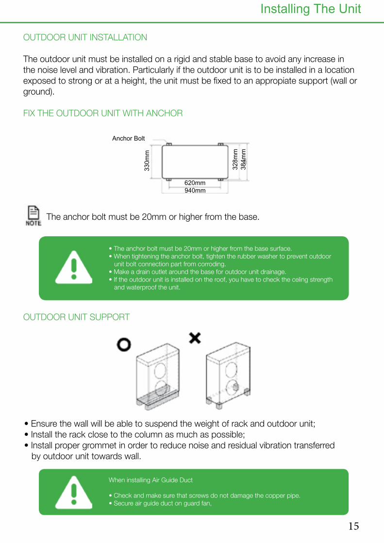
OUTDOOR UNIT INSTALLATION
The outdoor unit must be installed on a rigid and stable base to avoid any increase in the noise level and vibration. Particularly if the outdoor unit is to be installed in a location exposed to strong or at a height, the unit must be fixed to an appropiate support (wall or ground).
FIX THE OUTDOOR UNIT WITH ANCHOR
The anchor bolt must be 20mm or higher from the base.
• Ensure the wall will be able to suspend the weight of rack and outdoor unit;• Install the rack close to the column as much as possible;• Install proper grommet in order to reduce noise and residual vibration transferred by outdoor unit towards wall.
620mm 940mm
330m
m
328m
m
384m
m
Anchor Bolt
OUTDOOR UNIT SUPPORT
Installing The Unit
• The anchor bolt must be 20mm or higher from the base surface. • When tightening the anchor bolt, tighten the rubber washer to prevent outdoor unit bolt connection part from corroding.• Make a drain outlet around the base for outdoor unit drainage. • If the outdoor unit is installed on the roof, you have to check the celing strength and waterproof the unit.
When installing Air Guide Duct
• Check and make sure that screws do not damage the copper pipe.• Secure air guide duct on guard fan,
16
Heat Pump
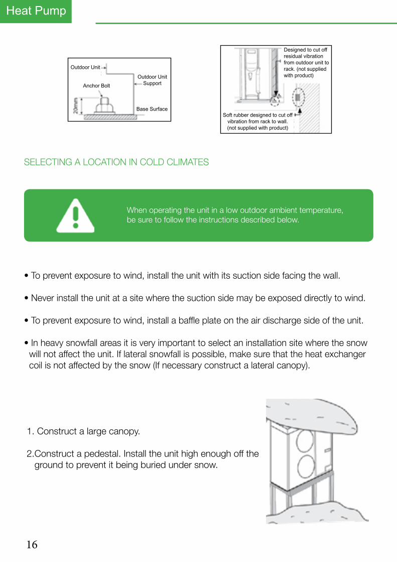
• To prevent exposure to wind, install the unit with its suction side facing the wall.
• Never install the unit at a site where the suction side may be exposed directly to wind.
• To prevent exposure to wind, install a baffle plate on the air discharge side of the unit.
• In heavy snowfall areas it is very important to select an installation site where the snow will not affect the unit. If lateral snowfall is possible, make sure that the heat exchanger coil is not affected by the snow (If necessary construct a lateral canopy).
1. Construct a large canopy.
2.Construct a pedestal. Install the unit high enough off the ground to prevent it being buried under snow.
Outdoor Unit
Anchor BoltOutdoor Unit
Support
Base Surface
Designed to cut offresidual vibrationfrom outdoor unit torack. (not suppliedwith product)
Soft rubber designed to cut offvibration from rack to wall.(not supplied with product)
SELECTING A LOCATION IN COLD CLIMATES
When operating the unit in a low outdoor ambient temperature, be sure to follow the instructions described below.

17
When the Air to Water Heat Pump is running in heating mode, ice can begin accumulate on the surface of the condenser.
To prevent ice from growing, the Heat Pump will go into defrost mode to melt the ice.
The water formed from the melted ice will fall to the base of the heat pump where it can es-cape to ground through the drain holes in the base. This will require a drain pit or soak hole beneath the Heat Pump to prevent water or ice from forming on the ground around the Heat Pump which may be a safety hazard.
If installing the Heat Pump on a wall, the supplied drain plug and drain hose can be fitted to pipe the water away to drain.
In case there is not enough space for drainage out of the unit, additional drain works are required.Follow the description as below
• Make space more than 100mm between the bottom of the outdoor unit and the ground for installation of the drain plug.•Insert the drain plug into the hole on the bottom of the outdoor unit.
• Connect the drain hose to the drain plug.
• Make sure dusts or small branches should not go into the drain hose.
• Considering the direction of strong wind, the out-door unit shall be installed. Strong wind can make the unit turned over so need to set side of the unit face the direction
of wind, not front.
• If drain work is not enough, it can lead to system performance degration
and system damages.
Strong Wind Strong Wind
Blown Wind
18
Heat Pump
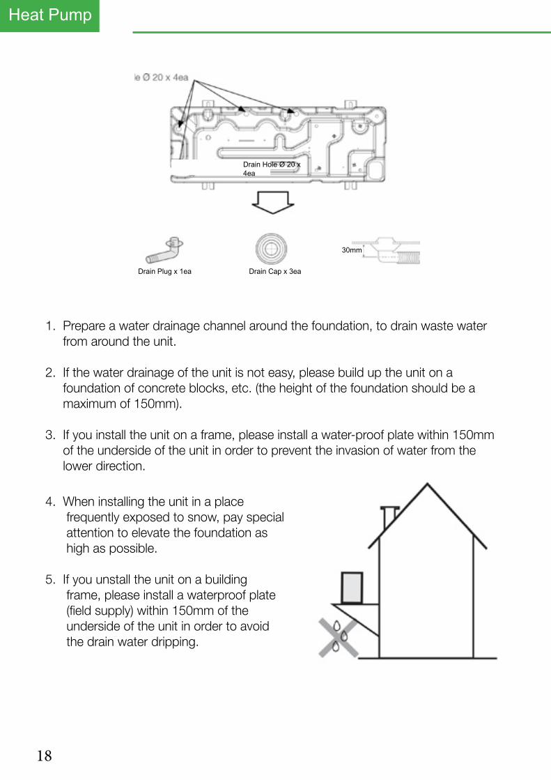
1. Prepare a water drainage channel around the foundation, to drain waste water from around the unit.
2. If the water drainage of the unit is not easy, please build up the unit on a foundation of concrete blocks, etc. (the height of the foundation should be a maximum of 150mm).
3. If you install the unit on a frame, please install a water-proof plate within 150mm of the underside of the unit in order to prevent the invasion of water from the lower direction.
4. When installing the unit in a place frequently exposed to snow, pay special attention to elevate the foundation as high as possible.
5. If you unstall the unit on a building frame, please install a waterproof plate (field supply) within 150mm of the underside of the unit in order to avoid the drain water dripping.
Drain Plug x 1ea Drain Cap x 3ea
30mm
Drain Hole Ø 20 x 4ea

19

20
Heat Pump
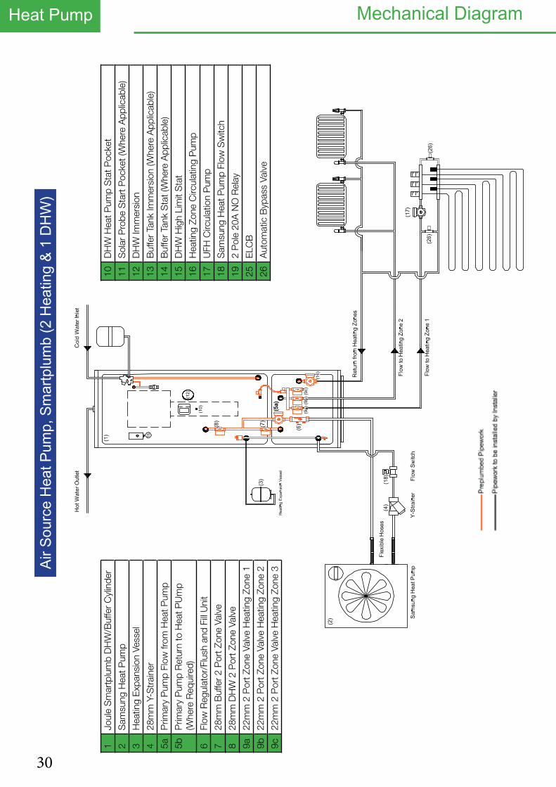
1Jo
ule
Sm
artp
lum
b D
HW
/Buf
fer
Cyl
inde
r
2S
amsu
ng H
eat P
ump
3H
eatin
g E
xpan
sion
Ves
sel
428
mm
Y-S
trai
ner
5aP
rimar
y P
ump
Flow
from
Hea
t Pum
p
5bP
rimar
y P
ump
Ret
urn
to H
eat P
Um
p (W
here
Req
uire
d)
6Fl
ow R
egul
ator
/Flu
sh a
nd F
ill U
nit
728
mm
Buf
fer
2 P
ort Z
one
Valv
e
828
mm
DH
W 2
Por
t Zon
e Va
lve
9a22
mm
2 P
ort Z
one
Valv
e H
eatin
g Zo
ne 1
9b22
mm
2 P
ort Z
one
Valv
e H
eatin
g Zo
ne 2
9c22
mm
2 P
ort Z
one
Valv
e H
eatin
g Zo
ne 3
10D
HW
Hea
t Pum
p S
tat P
ocke
t
11S
olar
Pro
be S
tart
Poc
ket (
Whe
re A
pplic
able
)
12D
HW
Imm
ersi
on
13B
uffe
r Ta
nk Im
mer
sion
(Whe
re A
pplic
able
)
14B
uffe
r Ta
nk S
tat (
Whe
re A
pplic
able
)
15D
HW
Hig
h Li
mit
Sta
t
16H
eatin
g Zo
ne C
ircul
atin
g P
ump
17U
FH C
ircul
atio
n P
ump
18S
amsu
ng H
eat P
ump
Flow
Sw
itch
192
Pol
e 20
A N
O R
elay
25E
LCB
26A
utom
atic
Byp
ass
Valv
e
Air S
ourc
e He
at P
ump,
Sm
artp
lum
b (1
Hea
ting
& 1
DHW
)LE
GE
ND
Mechanical Diagram

21
Electrical Diagram

22
Heat Pump Initial Start Up
Please refer to controller symbols and button functions on pages 60 & 61 for further guidance on the heat pump controls.
1. Ensure that both the outdoor and indoor units are correctly wired and plumbed prior to turning on.
2. Flush the system at 110% of system flow rate in both directions using suitable chemical.
3. Once the system has been power flushed you must now fill the system with Glycol.
4. The Glycol should be pre mixed before putting it into the system and a solar filling station is ideal for filling the system, use the connections on the fill/flush and flow meter to add the glycol.
5. Do not put Neat Glycol into the system, failure to do this may cause the glycol to block the heat exchanger or block the pipes within the heat emitter circuit.
6. Run the solar filling station for at least an hour to purge all the air from the system.
7. Turn on power to the indoor unit first. Then turn on power to the outdoor unit second.
8. The outdoor unit will start flashing numbers 00, 01,02, etc. It will then flash a message like 00 00, dE, F0 etc
9. Once 00 disappears and the controller is just showing the time the system is then ready for testing.
CHANGING THE BACK LIGHT SETTING
1. To change the back light setting from 5 seconds to 30 seconds push the user set button once.
2. The controller will show 1, use the up arrow to change this to 4.
3. Push the right arrow twice and then change the 5 to 30 using the up arrow.
4. Push the set button once.
5. Push Esc to return to the normal screen.

23
Push the Power on Button to start the pumps. With the pumps running check your flow rate on the flow meter, this should be reading above 16 LPM and the flow rate is measured from the bottom of the float.
Push the Mode button to bring on the immersion heater if using the system with a Cylinder, the Tap Symbol should appear this indicates that the heater is on.
Push the Outing button to force open the DHW valve, The cylinder Symbol should then appear to indicate that the DHW valve is open.
Now turn on the Room thermostats, 7E57 should now change to either Heat 1 or Heat 2 depending on what heating zone has been turned on. This indicates that the heat pump has received its run signal from the room stats.
Use the Timer button to view the temperature of the various sensors fitted to the heat pump.
To come out of the test mode push and hold the ESC button until the 7E57 clears from the display.
To electrically test the system you will need to put the unit into test mode.
To access the test mode push both the left and right hand keys together for 6 second. The controller will shoe 7E57 (Test) or Heat, The individual electrical components can now be tested.
Self Test Mode

24
Heat Pump
After carrying out the test function check the flow temperature of the system to ensure that the flow temperature is above 10°C. If the flow temperature is below 10°C then the outdoor unit will not start.
Press the timer button to see the flow temp. This needs to be above 10°C before the compressor will start.
Put the system back into test mode by pushing and holding the left and right hand keys together for 6 seconds until either 7EST or Heat is shown on the controller.
1. If the system temperature is below 10°C turn on the immersion heater whilst the unit is on test mode by pushing the Mode button and the immserion should appear on the controller.
2. Turn on the pumps by pushing the power button and the pump symbol should appearon the controller.
3. Force the hot water valve open by pushing the Outing button and the hot water symbol should appear . Leave the system to run like this until the flow tempera- ture reaches 15°C.
4. Now Re-Check the Flow Meter to ensure that the flow rate is over 16 L/min. If the flow rate is lower than 17L/min the unit will display a flow rate error “E911”.
5. Once the flow temperature has reached 15°C, take the machine out of test by holding the ESC key.
Cold Start

25
Field Setting ParametersField Setting Parameters
FIELD SETTING PARAMETERS FOR SMART PLUMBED CYLINDER UNITS - 2 ZONE
Note: If you set a field setting and go back to check it, it will not have changed. The field setting does not get written to th PCB unless you push SET after changing it.
Field Setting
Set to Description
20-11 -2 Low ambient temp setting for optimisation
20-12 +15 High ambient temp setting for optimisation
20-21 40°C or 45/50°C Maximum flow temperature for heating circuit 1 at set value of 2011.(This setting depends on what type of heat emitter circuit is being used, 40°C for under-floor at 150mm spacing and 45°C to 50°C for raditators dependent on over size factor.)
20-22 35°C or 40/45°C Minimum flow temperature for heating circuit 1 at set value of 2012.(This setting depends on what type of heat emitter circuit is being used, 35°C for under-floor at 150mm spacing and 40°C to 45°C for raditators dependent on over size factor.)
20-91 1 This tells the system to use the run signal from Zone 1
30-11 1 Tells the unit it has a cylinder connected.
30-25 200L cyl. = 50 mins.300L cyl. = 90 mins
Maximum cylinder heating time from heat pump before turning back to heating zonesM
30-32 200L cyl. = 50 mins.300L cyl. = 90 mins
Maximum cylinder heating time from heat pump before turning on immersion to support it.
30-42 T (Tuesday) Legionella function activates on this day.
30-43 3am Legionella function activates on this hour.
30-44 60°C Legionella function raises water temp to this.
30-51 - Enables the timer for DHW Boost mode.
30-52 60 Should automatically be set to 60 minutes, this is the max time in boost mode before the unit reverts back to normal operation.
Once the parameters have been set, push the Escape key once and the controller should revert back to just showing the time.
1. To access the field settings push and hold the down arrow and the set key together until the display shows “10”.2. Push the up arrow once to change 10 to 20.3. Push the right arrow once so the screen shows 2011.4. Push the right arrow again and the value for 2011 is shown, use the up and down arrows to change this value to the desired one.5. Once the value is changed you must push the SET key otherwise the change is not saved. Push the set key to save and a swirling line will appear, this indicated that the unit is saving the change.6. Push the left arrow so that 2011 flashes, then push the up arrow to change to 2012, repeat the above process for each parameter that needs to be adjusted.7. To move up a level in the menu system (Change from 20 codses to 30 codes) push the left arrow until the screen goes back to the inital setting i.e 20. Use the up arrow to change to 30, then push the right arrow to enter the menu (3011)8. Once you have completed adjusting the parameters, push the ESC key to return to the normal controller screen.
ACCESSING AND ADJUSTING THE FIELD SETTINGS

26
Heat Pump
1. To set the time push the USER set button once and 1 should appear on the controller.
2. Push the up arrow to change the 1 to a 2.
3. Push the right button twice and 21 should appear alonge with the year, use the up arrow to change the year and then push the SET key and 22 should appear.
4. Push the right button and the month should flash, use the up botton to change.
5. Push the right button and the day should flash, use the up button to change.
6. Push the Set button and 22 should flash, push the up button to change to 23.
7. Push the right arrow and the day and current time are shown, adjust the day with the up button.
8. Push the right button and AM or PM will flash, use the up button to change to AM or PM, if you have both AM and PM flashing this will change the clock to 24 hours.
9. Push right button and the hour will flash, use the up button to change the hour.
10. Push the right button and the minutes will flash, use the up button to change the minutes. Now push the set Key.
11. Push the escape button to return to the normal screen.
Setting The Clock

27
Before starting the heat pump make sure that all packaging is removed from the outdoor unit, and that the system is free of any air.
To start the heat pump follow the description below.
1. Push the On/Off button on the top left hand side of the controller, ‘AU’ should now appear on the controller, this means that the system is in Automatic mode.
2. Press the DHW power button. The DHW symbol will appear in the top right hand corner of the display.
3. Use the Mode button with the DHW section of the controller to change the Hot Water to two dots.
4. Push the oval set button and use the + / - buttons to adjust the set point for the Hot water, we recommend that this is set to 48°C.
5. The pump symbol should appear on the screen this indicates that the circulation pump is running.
6. After two minutes the cylinder symbol should appear , this shows that the heat pump is ready for hot water preparation.
7. Within 3 minutes this symbol should appear . This indicates that the outdoor unit is now running.
8. The heat pump will prioritise Hot water, so allow the cylinder to reach temperature before testing the heating circuit.
9. Turn up the room thermostats, once the cylinder is at tempetature the heat pump should automatically change over onto space heating.
10. When the heat pump is in space heating mode the only symbols to be displayed will be to show that the circulation pump is running and to show that the heat pump is running.
11. Check the flow temperatures by pushing the view button.
12. The system is now set and running.
Starting The Heat Pump
28
Heat Pump Setting The DHW Daily Timer
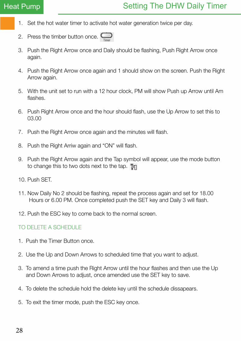
1. Set the hot water timer to activate hot water generation twice per day.
2. Press the timber button once.
3. Push the Right Arrow once and Daily should be flashing, Push Right Arrow once again.
4. Push the Right Arrow once again and 1 should show on the screen. Push the Right Arrow again.
5. With the unit set to run with a 12 hour clock, PM will show Push up Arrow until Am flashes.
6. Push Right Arrow once and the hour should flash, use the Up Arrow to set this to 03.00
7. Push the Right Arrow once again and the minutes will flash.
8. Push the Right Arriw again and “ON” will flash.
9. Push the Right Arrow again and the Tap symbol will appear, use the mode button to change this to two dots next to the tap.
10. Push SET.
11. Now Daily No 2 should be flashing, repeat the process again and set for 18.00 Hours or 6.00 PM. Once completed push the SET key and Daily 3 will flash.
12. Push the ESC key to come back to the normal screen.
TO DELETE A SCHEDULE
1. Push the Timer Button once.
2. Use the Up and Down Arrows to scheduled time that you want to adjust.
3. To amend a time push the Right Arrow until the hour flashes and then use the Up and Down Arrows to adjust, once amended use the SET key to save.
4. To delete the schedule hold the delete key until the schedule dissapears.
5. To exit the timer mode, push the ESC key once.
29
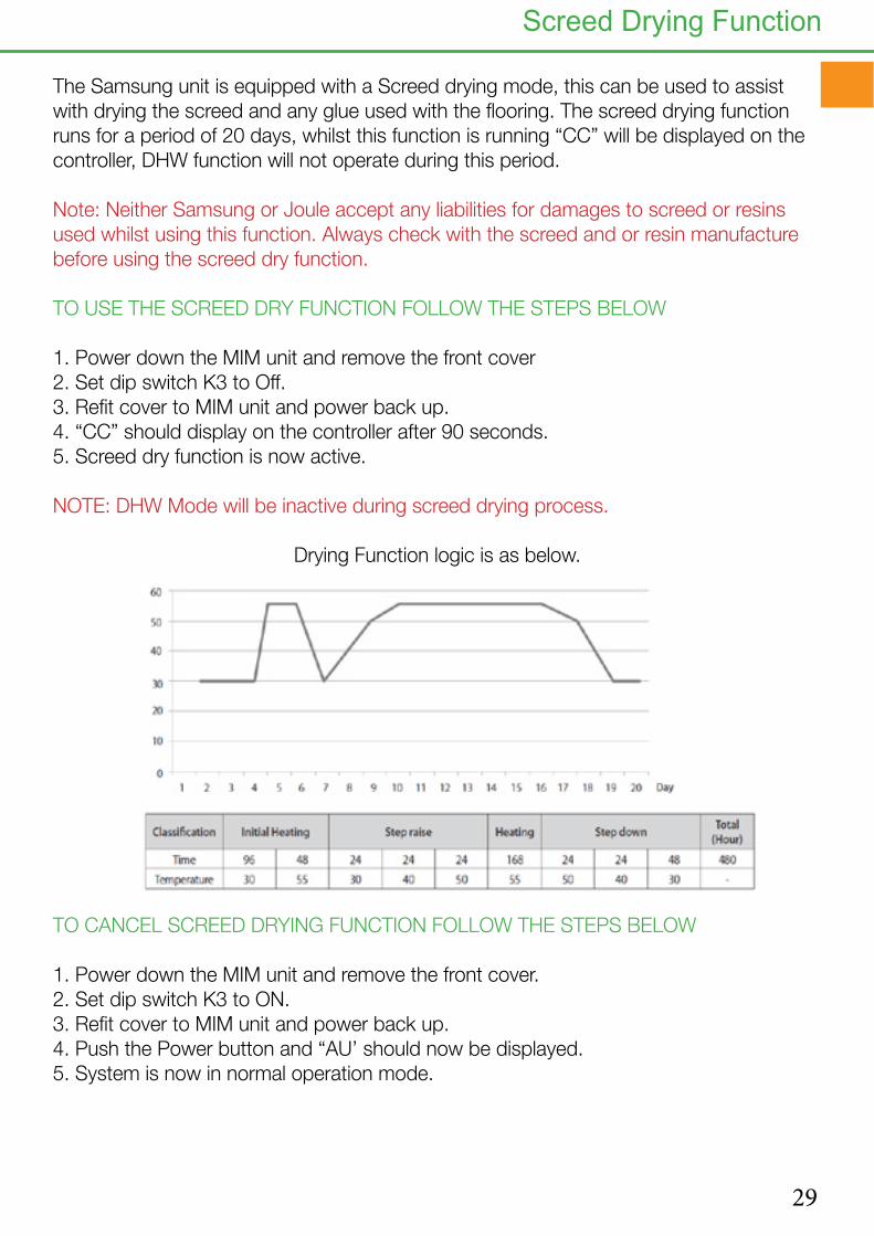
The Samsung unit is equipped with a Screed drying mode, this can be used to assist with drying the screed and any glue used with the flooring. The screed drying function runs for a period of 20 days, whilst this function is running “CC” will be displayed on the controller, DHW function will not operate during this period.
Note: Neither Samsung or Joule accept any liabilities for damages to screed or resins used whilst using this function. Always check with the screed and or resin manufacture before using the screed dry function.
TO USE THE SCREED DRY FUNCTION FOLLOW THE STEPS BELOW
1. Power down the MIM unit and remove the front cover2. Set dip switch K3 to Off.3. Refit cover to MIM unit and power back up.4. “CC” should display on the controller after 90 seconds.5. Screed dry function is now active.
NOTE: DHW Mode will be inactive during screed drying process.
Drying Function logic is as below.
TO CANCEL SCREED DRYING FUNCTION FOLLOW THE STEPS BELOW
1. Power down the MIM unit and remove the front cover.2. Set dip switch K3 to ON.3. Refit cover to MIM unit and power back up.4. Push the Power button and “AU’ should now be displayed.5. System is now in normal operation mode.
Screed Drying Function
30
Heat Pump Mechanical DiagramAi
r Sou
rce
Heat
Pum
p, S
mar
tplu
mb
(2 H
eatin
g &
1 DH
W)
1Jo
ule
Sm
artp
lum
b D
HW
/Buf
fer
Cyl
inde
r
2S
amsu
ng H
eat P
ump
3H
eatin
g E
xpan
sion
Ves
sel
428
mm
Y-S
trai
ner
5aP
rimar
y P
ump
Flow
from
Hea
t Pum
p
5bP
rimar
y P
ump
Ret
urn
to H
eat P
Um
p (W
here
Req
uire
d)
6Fl
ow R
egul
ator
/Flu
sh a
nd F
ill U
nit
728
mm
Buf
fer
2 P
ort Z
one
Valv
e
828
mm
DH
W 2
Por
t Zon
e Va
lve
9a22
mm
2 P
ort Z
one
Valv
e H
eatin
g Zo
ne 1
9b22
mm
2 P
ort Z
one
Valv
e H
eatin
g Zo
ne 2
9c22
mm
2 P
ort Z
one
Valv
e H
eatin
g Zo
ne 3
10D
HW
Hea
t Pum
p S
tat P
ocke
t
11S
olar
Pro
be S
tart
Poc
ket (
Whe
re A
pplic
able
)
12D
HW
Imm
ersi
on
13B
uffe
r Ta
nk Im
mer
sion
(Whe
re A
pplic
able
)
14B
uffe
r Ta
nk S
tat (
Whe
re A
pplic
able
)
15D
HW
Hig
h Li
mit
Sta
t
16H
eatin
g Zo
ne C
ircul
atin
g P
ump
17U
FH C
ircul
atio
n P
ump
18S
amsu
ng H
eat P
ump
Flow
Sw
itch
192
Pol
e 20
A N
O R
elay
25E
LCB
26A
utom
atic
Byp
ass
Valv
e

31
Electrical Diagram

32
Heat Pump Initial Start Up
Please refer to controller symbols and button functions on pages 60 & 61 for further guidance on the heat pump controls.
1. Ensure that both the outdoor and indoor units are correctly wired and plumbed prior to turning on.
2. Flush the system at 110% of system flow rate in both directions using suitable chemical.
3. Once the system has been power flushed you must now fill the system with Glycol.
4. The Glycol should be pre mixed before putting it into the system and a solar filling station is ideal for filling the system, use the connections on the fill/flush and flow meter to add the glycol.
5. Do not put Neat Glycol into the system, failure to do this may cause the glycol to block the heat exchanger or block the pipes within the heat emitter circuit.
6. Run the solar filling station for at least an hour to purge all the air from the system.
7. Turn on power to the indoor unit first. Then turn on power to the outdoor unit second.
8. The outdoor unit will start flashing numbers 00, 01,02, etc. It will then flash a message like 00 00, dE, F0 etc
9. Once 00 disappears and the controller is just showing the time the system is then ready for testing.
CHANGING THE BACK LIGHT SETTING
1. To change the back light setting from 5 seconds to 30 seconds push the user set button once.
2. The controller will show 1, use the up arrow to change this to 4.
3. Push the right arrow twice and then change the 5 to 30 using the up arrow.
4. Push the set button once.
5. Push Esc to return to the normal screen.

33
Push the Power on Button to start the pumps. With the pumps running check your flow rate on the flow meter, this should be reading above 16 LPM and the flow rate is measured from the bottom of the float.
Push the Mode button to bring on the immersion heater if using the system with a Cylinder, the Tap Symbol should appear this indicates that the heater is on.
Push the Outing button to force open the DHW valve, The cylinder Symbol should then appear to indicate that the DHW valve is open.
Now turn on the Room thermostats, 7E57 should now change to either Heat 1 or Heat 2 depending on what heating zone has been turned on. This indicates that the heat pump has received its run signal from the room stats.
Use the Timer button to view the temperature of the various sensors fitted to the heat pump.
To come out of the test mode push and hold the ESC button until the 7E57 clears from the display.
To electrically test the system you will need to put the unit into test mode.
To access the test mode push both the left and right hand keys together for 6 second. The controller will shoe 7E57 (Test) or Heat, The individual electrical components can now be tested.
Self Test Mode

34
Heat Pump
After carrying out the test function check the flow temperature of the system to ensure that the flow temperature is above 10°C. If the flow temperature is below 10°C then the outdoor unit will not start.
Press the timer button to see the flow temp. This needs to be above 10°C before the compressor will start.
Put the system back into test mode by pushing and holding the left and right hand keys together for 6 seconds until either 7EST or Heat is shown on the controller.
1. If the system temperature is below 10°C turn on the immersion heater whilst the unit is on test mode by pushing the Mode button and the immserion should appear on the controller.
2. Turn on the pumps by pushing the power button and the pump symbol should appearon the controller.
3. Force the hot water valve open by pushing the Outing button and the hot water symbol should appear . Leave the system to run like this until the flow tempera- ture reaches 15°C.
4. Now Re-Check the Flow Meter to ensure that the flow rate is over 16 L/min. If the flow rate is lower than 17L/min the unit will display a flow rate error “E911”.
5. Once the flow temperature has reached 15°C, take the machine out of test by holding the ESC key.
Cold Start

35
Field Setting ParametersField Setting Parameters
FIELD SETTING PARAMETERS FOR SMART PLUMBED CYLINDER UNITS - 3 ZONE
Note: If you set a field setting and go back to check it, it will not have changed. The field setting does not get written to th PCB unless you push SET after changing it.
Field Setting
Set to Description
20-11 -2 Low ambient temp setting for optimisation
20-12 +15 High ambient temp setting for optimisation
20-21 40°C or 45/50°C Maximum flow temperature for heating circuit 1 at set value of 2011.(This setting depends on what type of heat emitter circuit is being used, 40°C for under-floor at 150mm spacing and 45°C to 50°C for raditators dependent on over size factor.)
20-22 35°C or 40/45°C Minimum flow temperature for heating circuit 1 at set value of 2012.(This setting depends on what type of heat emitter circuit is being used, 35°C for under-floor at 150mm spacing and 40°C to 45°C for raditators dependent on over size factor.)
20-91 1 This tells the system to use the run signal from Zone 1
30-11 1 Tells the unit it has a cylinder connected.
30-25 200L cyl. = 50 mins.300L cyl. = 90 mins
Maximum cylinder heating time from heat pump before turning back to heating zonesM
30-32 200L cyl. = 50 mins.300L cyl. = 90 mins
Maximum cylinder heating time from heat pump before turning on immersion to support it.
30-42 T (Tuesday) Legionella function activates on this day.
30-43 3am Legionella function activates on this hour.
30-44 60°C Legionella function raises water temp to this.
30-51 - Enables the timer for DHW Boost mode.
30-52 60 Should automatically be set to 60 minutes, this is the max time in boost mode before the unit reverts back to normal operation.
Once the parameters have been set, push the Escape key once and the controller should revert back to just showing the time.
1. To access the field settings push and hold the down arrow and the set key together until the display shows “10”.2. Push the up arrow once to change 10 to 20.3. Push the right arrow once so the screen shows 2011.4. Push the right arrow again and the value for 2011 is shown, use the up and down arrows to change this value to the desired one.5. Once the value is changed you must push the SET key otherwise the change is not saved. Push the set key to save and a swirling line will appear, this indicated that the unit is saving the change.6. Push the left arrow so that 2011 flashes, then push the up arrow to change to 2012, repeat the above process for each parameter that needs to be adjusted.7. To move up a level in the menu system (Change from 20 codses to 30 codes) push the left arrow until the screen goes back to the inital setting i.e 20. Use the up arrow to change to 30, then push the right arrow to enter the menu (3011)8. Once you have completed adjusting the parameters, push the ESC key to return to the normal controller screen.
ACCESSING AND ADJUSTING THE FIELD SETTINGS

36
Heat Pump
1. To set the time push the USER set button once and 1 should appear on the controller.
2. Push the up arrow to change the 1 to a 2.
3. Push the right button twice and 21 should appear alonge with the year, use the up arrow to change the year and then push the SET key and 22 should appear.
4. Push the right button and the month should flash, use the up botton to change.
5. Push the right button and the day should flash, use the up button to change.
6. Push the Set button and 22 should flash, push the up button to change to 23.
7. Push the right arrow and the day and current time are shown, adjust the day with the up button.
8. Push the right button and AM or PM will flash, use the up button to change to AM or PM, if you have both AM and PM flashing this will change the clock to 24 hours.
9. Push right button and the hour will flash, use the up button to change the hour.
10. Push the right button and the minutes will flash, use the up button to change the minutes. Now push the set Key.
11. Push the escape button to return to the normal screen.
Setting The Clock

37
Before starting the heat pump make sure that all packaging is removed from the outdoor unit, and that the system is free of any air.
To start the heat pump follow the description below.
1. Push the On/Off button on the top left hand side of the controller, ‘AU’ should now appear on the controller, this means that the system is in Automatic mode.
2. Press the DHW power button. The DHW symbol will appear in the top right hand corner of the display.
3. Use the Mode button with the DHW section of the controller to change the Hot Water to two dots.
4. Push the oval set button and use the + / - buttons to adjust the set point for the Hot water, we recommend that this is set to 48°C.
5. The pump symbol should appear on the screen this indicates that the circulation pump is running.
6. After two minutes the cylinder symbol should appear , this shows that the heat pump is ready for hot water preparation.
7. Within 3 minutes this symbol should appear . This indicates that the outdoor unit is now running.
8. The heat pump will prioritise Hot water, so allow the cylinder to reach temperature before testing the heating circuit.
9. Turn up the room thermostats, once the cylinder is at tempetature the heat pump should automatically change over onto space heating.
10. When the heat pump is in space heating mode the only symbols to be displayed will be to show that the circulation pump is running and to show that the heat pump is running.
11. Check the flow temperatures by pushing the view button.
12. The system is now set and running.
Starting The Heat Pump

38
Heat Pump Setting The DHW Daily Timer
1. Set the hot water timer to activate hot water generation twice per day.
2. Press the timber button once.
3. Push the Right Arrow once and Daily should be flashing, Push Right Arrow once again.
4. Push the Right Arrow once again and 1 should show on the screen. Push the Right Arrow again.
5. With the unit set to run with a 12 hour clock, PM will show Push up Arrow until Am flashes.
6. Push Right Arrow once and the hour should flash, use the Up Arrow to set this to 03.00
7. Push the Right Arrow once again and the minutes will flash.
8. Push the Right Arriw again and “ON” will flash.
9. Push the Right Arrow again and the Tap symbol will appear, use the mode button to change this to two dots next to the tap.
10. Push SET.
11. Now Daily No 2 should be flashing, repeat the process again and set for 18.00 Hours or 6.00 PM. Once completed push the SET key and Daily 3 will flash.
12. Push the ESC key to come back to the normal screen.
TO DELETE A SCHEDULE
1. Push the Timer Button once.
2. Use the Up and Down Arrows to scheduled time that you want to adjust.
3. To amend a time push the Right Arrow until the hour flashes and then use the Up and Down Arrows to adjust, once amended use the SET key to save.
4. To delete the schedule hold the delete key until the schedule dissapears.
5. To exit the timer mode, push the ESC key once.

39
The Samsung unit is equipped with a Screed drying mode, this can be used to assist with drying the screed and any glue used with the flooring. The screed drying function runs for a period of 20 days, whilst this function is running “CC” will be displayed on the controller, DHW function will not operate during this period.
Note: Neither Samsung or Joule accept any liabilities for damages to screed or resins used whilst using this function. Always check with the screed and or resin manufacture before using the screed dry function.
TO USE THE SCREED DRY FUNCTION FOLLOW THE STEPS BELOW
1. Power down the MIM unit and remove the front cover2. Set dip switch K3 to Off.3. Refit cover to MIM unit and power back up.4. “CC” should display on the controller after 90 seconds.5. Screed dry function is now active.
NOTE: DHW Mode will be inactive during screed drying process.
Drying Function logic is as below.
TO CANCEL SCREED DRYING FUNCTION FOLLOW THE STEPS BELOW
1. Power down the MIM unit and remove the front cover.2. Set dip switch K3 to ON.3. Refit cover to MIM unit and power back up.4. Push the Power button and “AU’ should now be displayed.5. System is now in normal operation mode.
Screed Drying Function

40
Heat Pump Mechanical Diagram
1Jo
ule
Sm
artp
lum
b D
HW
/Buf
fer
Cyl
inde
r
2S
amsu
ng H
eat P
ump
3H
eatin
g E
xpan
sion
Ves
sel
428
mm
Y-S
trai
ner
5aP
rimar
y P
ump
Flow
from
Hea
t Pum
p
5bP
rimar
y P
ump
Ret
urn
to H
eat P
Um
p (W
here
R
equi
red)
6Fl
ow R
egul
ator
/Flu
sh a
nd F
ill U
nit
728
mm
Buf
fer
2 P
ort Z
one
Valv
e
828
mm
DH
W 2
Por
t Zon
e Va
lve
9a22
mm
2 P
ort Z
one
Valv
e H
eatin
g Zo
ne 1
9b22
mm
2 P
ort Z
one
Valv
e H
eatin
g Zo
ne 2
9c22
mm
2 P
ort Z
one
Valv
e H
eatin
g Zo
ne 3
10D
HW
Hea
t Pum
p S
tat P
ocke
t
11S
olar
Pro
be S
tart
Poc
ket (
Whe
re A
pplic
able
)
12D
HW
Imm
ersi
on
13B
uffe
r Ta
nk Im
mer
sion
(Whe
re A
pplic
able
)
14B
uffe
r Ta
nk S
tat (
Whe
re A
pplic
able
)
15D
HW
Hig
h Li
mit
Sta
t
16H
eatin
g Zo
ne C
ircul
atin
g P
ump
17U
FH C
ircul
atio
n P
ump
18S
amsu
ng H
eat P
ump
Flow
Sw
itch
192
Pol
e 20
A N
O R
elay
25E
LCB
LEG
EN
DAi
r Sou
rce
Heat
Pum
p, H
igh
Gai
n In
dire
ct (1
Hea
ting
& 1
DHW
)

41
Electrical Diagram

42
Heat Pump Initial Start Up
Please refer to controller symbols and button functions on pages 60 & 61 for further guidance on the heat pump controls.
1. Ensure that both the outdoor and indoor units are correctly wired and plumbed prior to turning on.
2. Flush the system at 110% of system flow rate in both directions using suitable chemical.
3. Once the system has been power flushed you must now fill the system with Glycol.
4. The Glycol should be pre mixed before putting it into the system and a solar filling station is ideal for filling the system, use the connections on the fill/flush and flow meter to add the glycol.
5. Do not put Neat Glycol into the system, failure to do this may cause the glycol to block the heat exchanger or block the pipes within the heat emitter circuit.
6. Run the solar filling station for at least an hour to purge all the air from the system.
7. Turn on power to the indoor unit first. Then turn on power to the outdoor unit second.
8. The outdoor unit will start flashing numbers 00, 01,02, etc. It will then flash a message like 00 00, dE, F0 etc
9. Once 00 disappears and the controller is just showing the time the system is then ready for testing.
CHANGING THE BACK LIGHT SETTING
1. To change the back light setting from 5 seconds to 30 seconds push the user set button once.
2. The controller will show 1, use the up arrow to change this to 4.
3. Push the right arrow twice and then change the 5 to 30 using the up arrow.
4. Push the set button once.
5. Push Esc to return to the normal screen.

43
Push the Power on Button to start the pumps. With the pumps running check your flow rate on the flow meter, this should be reading above 16 LPM and the flow rate is measured from the bottom of the float.
Push the Mode button to bring on the immersion heater if using the system with a Cylinder, the Tap Symbol should appear this indicates that the heater is on.
Push the Outing button to force open the DHW valve, The cylinder Symbol should then appear to indicate that the DHW valve is open.
Now turn on the Room thermostats, 7E57 should now change to either Heat 1 or Heat 2 depending on what heating zone has been turned on. This indicates that the heat pump has received its run signal from the room stats.
Use the Timer button to view the temperature of the various sensors fitted to the heat pump.
To come out of the test mode push and hold the ESC button until the 7E57 clears from the display.
To electrically test the system you will need to put the unit into test mode.
To access the test mode push both the left and right hand keys together for 6 second. The controller will shoe 7E57 (Test) or Heat, The individual electrical components can now be tested.
Self Test Mode

44
Heat Pump
After carrying out the test function check the flow temperature of the system to ensure that the flow temperature is above 10°C. If the flow temperature is below 10°C then the outdoor unit will not start.
Press the timer button to see the flow temp. This needs to be above 10°C before the compressor will start.
Put the system back into test mode by pushing and holding the left and right hand keys together for 6 seconds until either 7EST or Heat is shown on the controller.
1. If the system temperature is below 10°C turn on the immersion heater whilst the unit is on test mode by pushing the Mode button and the immserion should appear on the controller.
2. Turn on the pumps by pushing the power button and the pump symbol should appearon the controller.
3. Force the hot water valve open by pushing the Outing button and the hot water symbol should appear . Leave the system to run like this until the flow tempera- ture reaches 15°C.
4. Now Re-Check the Flow Meter to ensure that the flow rate is over 16 L/min. If the flow rate is lower than 17L/min the unit will display a flow rate error “E911”.
5. Once the flow temperature has reached 15°C, take the machine out of test by holding the ESC key.
Cold Start

45
Field Setting ParametersField Setting Parameters
FIELD SETTING PARAMETERS FOR PRE PLUMBED CYLINDER UNITS - 2 ZONE
Note: If you set a field setting and go back to check it, it will not have changed. The field setting does not get written to th PCB unless you push SET after changing it.
Field Setting
Set to Description
20-11 -2 Low ambient temp setting for optimisation
20-12 +15 High ambient temp setting for optimisation
20-21 40°C or 45/50°C Maximum flow temperature for heating circuit 1 at set value of 2011.(This setting depends on what type of heat emitter circuit is being used, 40°C for under-floor at 150mm spacing and 45°C to 50°C for raditators dependent on over size factor.)
20-22 35°C or 40/45°C Minimum flow temperature for heating circuit 1 at set value of 2012.(This setting depends on what type of heat emitter circuit is being used, 35°C for under-floor at 150mm spacing and 40°C to 45°C for raditators dependent on over size factor.)
20-91 1 This tells the system to use the run signal from Zone 1
30-11 1 Tells the unit it has a cylinder connected.
30-25 200L cyl. = 50 mins.300L cyl. = 90 mins
Maximum cylinder heating time from heat pump before turning back to heating zonesM
30-32 200L cyl. = 50 mins.300L cyl. = 90 mins
Maximum cylinder heating time from heat pump before turning on immersion to support it.
30-42 T (Tuesday) Legionella function activates on this day.
30-43 3am Legionella function activates on this hour.
30-44 60°C Legionella function raises water temp to this.
30-51 - Enables the timer for DHW Boost mode.
30-52 60 Should automatically be set to 60 minutes, this is the max time in boost mode before the unit reverts back to normal operation.
Once the parameters have been set, push the Escape key once and the controller should revert back to just showing the time.
1. To access the field settings push and hold the down arrow and the set key together until the display shows “10”.2. Push the up arrow once to change 10 to 20.3. Push the right arrow once so the screen shows 2011.4. Push the right arrow again and the value for 2011 is shown, use the up and down arrows to change this value to the desired one.5. Once the value is changed you must push the SET key otherwise the change is not saved. Push the set key to save and a swirling line will appear, this indicated that the unit is saving the change.6. Push the left arrow so that 2011 flashes, then push the up arrow to change to 2012, repeat the above process for each parameter that needs to be adjusted.7. To move up a level in the menu system (Change from 20 codses to 30 codes) push the left arrow until the screen goes back to the inital setting i.e 20. Use the up arrow to change to 30, then push the right arrow to enter the menu (3011)8. Once you have completed adjusting the parameters, push the ESC key to return to the normal controller screen.
ACCESSING AND ADJUSTING THE FIELD SETTINGS
46
Heat Pump
1. To set the time push the USER set button once and 1 should appear on the controller.
2. Push the up arrow to change the 1 to a 2.
3. Push the right button twice and 21 should appear alonge with the year, use the up arrow to change the year and then push the SET key and 22 should appear.
4. Push the right button and the month should flash, use the up botton to change.
5. Push the right button and the day should flash, use the up button to change.
6. Push the Set button and 22 should flash, push the up button to change to 23.
7. Push the right arrow and the day and current time are shown, adjust the day with the up button.
8. Push the right button and AM or PM will flash, use the up button to change to AM or PM, if you have both AM and PM flashing this will change the clock to 24 hours.
9. Push right button and the hour will flash, use the up button to change the hour.
10. Push the right button and the minutes will flash, use the up button to change the minutes. Now push the set Key.
11. Push the escape button to return to the normal screen.
Setting The Clock

47
Before starting the heat pump make sure that all packaging is removed from the outdoor unit, and that the system is free of any air.
To start the heat pump follow the description below.
1. Push the On/Off button on the top left hand side of the controller, ‘AU’ should now appear on the controller, this means that the system is in Automatic mode.
2. Press the DHW power button. The DHW symbol will appear in the top right hand corner of the display.
3. Use the Mode button with the DHW section of the controller to change the Hot Water to two dots.
4. Push the oval set button and use the + / - buttons to adjust the set point for the Hot water, we recommend that this is set to 48°C.
5. The pump symbol should appear on the screen this indicates that the circulation pump is running.
6. After two minutes the cylinder symbol should appear , this shows that the heat pump is ready for hot water preparation.
7. Within 3 minutes this symbol should appear . This indicates that the outdoor unit is now running.
8. The heat pump will prioritise Hot water, so allow the cylinder to reach temperature before testing the heating circuit.
9. Turn up the room thermostats, once the cylinder is at tempetature the heat pump should automatically change over onto space heating.
10. When the heat pump is in space heating mode the only symbols to be displayed will be to show that the circulation pump is running and to show that the heat pump is running.
11. Check the flow temperatures by pushing the view button.
12. The system is now set and running.
Starting The Heat Pump

48
Heat Pump Setting The DHW Daily Timer
1. Set the hot water timer to activate hot water generation twice per day.
2. Press the timber button once.
3. Push the Right Arrow once and Daily should be flashing, Push Right Arrow once again.
4. Push the Right Arrow once again and 1 should show on the screen. Push the Right Arrow again.
5. With the unit set to run with a 12 hour clock, PM will show Push up Arrow until Am flashes.
6. Push Right Arrow once and the hour should flash, use the Up Arrow to set this to 03.00
7. Push the Right Arrow once again and the minutes will flash.
8. Push the Right Arriw again and “ON” will flash.
9. Push the Right Arrow again and the Tap symbol will appear, use the mode button to change this to two dots next to the tap.
10. Push SET.
11. Now Daily No 2 should be flashing, repeat the process again and set for 18.00 Hours or 6.00 PM. Once completed push the SET key and Daily 3 will flash.
12. Push the ESC key to come back to the normal screen.
TO DELETE A SCHEDULE
1. Push the Timer Button once.
2. Use the Up and Down Arrows to scheduled time that you want to adjust.
3. To amend a time push the Right Arrow until the hour flashes and then use the Up and Down Arrows to adjust, once amended use the SET key to save.
4. To delete the schedule hold the delete key until the schedule dissapears.
5. To exit the timer mode, push the ESC key once.
49
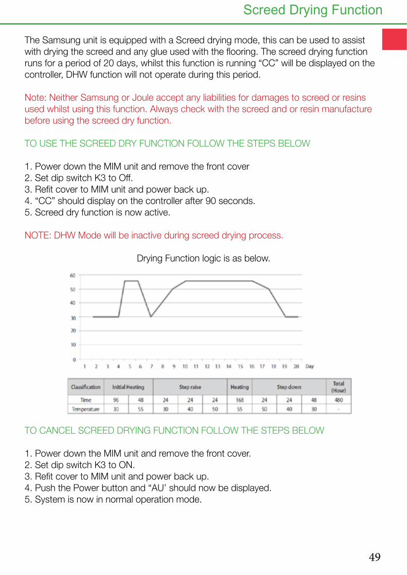
The Samsung unit is equipped with a Screed drying mode, this can be used to assist with drying the screed and any glue used with the flooring. The screed drying function runs for a period of 20 days, whilst this function is running “CC” will be displayed on the controller, DHW function will not operate during this period.
Note: Neither Samsung or Joule accept any liabilities for damages to screed or resins used whilst using this function. Always check with the screed and or resin manufacture before using the screed dry function.
TO USE THE SCREED DRY FUNCTION FOLLOW THE STEPS BELOW
1. Power down the MIM unit and remove the front cover2. Set dip switch K3 to Off.3. Refit cover to MIM unit and power back up.4. “CC” should display on the controller after 90 seconds.5. Screed dry function is now active.
NOTE: DHW Mode will be inactive during screed drying process.
Drying Function logic is as below.
TO CANCEL SCREED DRYING FUNCTION FOLLOW THE STEPS BELOW
1. Power down the MIM unit and remove the front cover.2. Set dip switch K3 to ON.3. Refit cover to MIM unit and power back up.4. Push the Power button and “AU’ should now be displayed.5. System is now in normal operation mode.
Screed Drying Function

50
Heat Pump Mechanical Diagram
1Jo
ule
Sm
artp
lum
b D
HW
/Buf
fer
Cyl
inde
r
2S
amsu
ng H
eat P
ump
3H
eatin
g E
xpan
sion
Ves
sel
428
mm
Y-S
trai
ner
5aP
rimar
y P
ump
Flow
from
Hea
t Pum
p
5bP
rimar
y P
ump
Ret
urn
to H
eat P
Um
p (W
here
R
equi
red)
6Fl
ow R
egul
ator
/Flu
sh a
nd F
ill U
nit
728
mm
Buf
fer
2 P
ort Z
one
Valv
e
828
mm
DH
W 2
Por
t Zon
e Va
lve
9a22
mm
2 P
ort Z
one
Valv
e H
eatin
g Zo
ne 1
9b22
mm
2 P
ort Z
one
Valv
e H
eatin
g Zo
ne 2
9c22
mm
2 P
ort Z
one
Valv
e H
eatin
g Zo
ne 3
10D
HW
Hea
t Pum
p S
tat P
ocke
t
11S
olar
Pro
be S
tart
Poc
ket (
Whe
re A
pplic
able
)
12D
HW
Imm
ersi
on
13B
uffe
r Ta
nk Im
mer
sion
(Whe
re A
pplic
able
)
14B
uffe
r Ta
nk S
tat (
Whe
re A
pplic
able
)
15D
HW
Hig
h Li
mit
Sta
t
16H
eatin
g Zo
ne C
ircul
atin
g P
ump
17U
FH C
ircul
atio
n P
ump
18S
amsu
ng H
eat P
ump
Flow
Sw
itch
192
Pol
e 20
A N
O R
elay
25E
LCB
Air S
ourc
e He
at P
ump,
Hig
h G
ain
Indi
rect
(2 H
eatin
g &
1 DH
W)
LEG
EN
D

51
Electrical Diagram

52
Heat Pump Initial Start Up
Please refer to controller symbols and button functions on pages 60 & 61 for further guidance on the heat pump controls.
1. Ensure that both the outdoor and indoor units are correctly wired and plumbed prior to turning on.
2. Flush the system at 110% of system flow rate in both directions using suitable chemical.
3. Once the system has been power flushed you must now fill the system with Glycol.
4. The Glycol should be pre mixed before putting it into the system and a solar filling station is ideal for filling the system, use the connections on the fill/flush and flow meter to add the glycol.
5. Do not put Neat Glycol into the system, failure to do this may cause the glycol to block the heat exchanger or block the pipes within the heat emitter circuit.
6. Run the solar filling station for at least an hour to purge all the air from the system.
7. Turn on power to the indoor unit first. Then turn on power to the outdoor unit second.
8. The outdoor unit will start flashing numbers 00, 01,02, etc. It will then flash a message like 00 00, dE, F0 etc
9. Once 00 disappears and the controller is just showing the time the system is then ready for testing.
CHANGING THE BACK LIGHT SETTING
1. To change the back light setting from 5 seconds to 30 seconds push the user set button once.
2. The controller will show 1, use the up arrow to change this to 4.
3. Push the right arrow twice and then change the 5 to 30 using the up arrow.
4. Push the set button once.
5. Push Esc to return to the normal screen.

53
Push the Power on Button to start the pumps. With the pumps running check your flow rate on the flow meter, this should be reading above 16 LPM and the flow rate is measured from the bottom of the float.
Push the Mode button to bring on the immersion heater if using the system with a Cylinder, the Tap Symbol should appear this indicates that the heater is on.
Push the Outing button to force open the DHW valve, The cylinder Symbol should then appear to indicate that the DHW valve is open.
Now turn on the Room thermostats, 7E57 should now change to either Heat 1 or Heat 2 depending on what heating zone has been turned on. This indicates that the heat pump has received its run signal from the room stats.
Use the Timer button to view the temperature of the various sensors fitted to the heat pump.
To come out of the test mode push and hold the ESC button until the 7E57 clears from the display.
To electrically test the system you will need to put the unit into test mode.
To access the test mode push both the left and right hand keys together for 6 second. The controller will shoe 7E57 (Test) or Heat, The individual electrical components can now be tested.
Self Test Mode
54
Heat Pump
After carrying out the test function check the flow temperature of the system to ensure that the flow temperature is above 10°C. If the flow temperature is below 10°C then the outdoor unit will not start.
Press the timer button to see the flow temp. This needs to be above 10°C before the compressor will start.
Put the system back into test mode by pushing and holding the left and right hand keys together for 6 seconds until either 7EST or Heat is shown on the controller.
1. If the system temperature is below 10°C turn on the immersion heater whilst the unit is on test mode by pushing the Mode button and the immserion should appear on the controller.
2. Turn on the pumps by pushing the power button and the pump symbol should appearon the controller.
3. Force the hot water valve open by pushing the Outing button and the hot water symbol should appear . Leave the system to run like this until the flow tempera- ture reaches 15°C.
4. Now Re-Check the Flow Meter to ensure that the flow rate is over 16 L/min. If the flow rate is lower than 17L/min the unit will display a flow rate error “E911”.
5. Once the flow temperature has reached 15°C, take the machine out of test by holding the ESC key.
Cold Start

55
Field Setting Parameters
FIELD SETTING PARAMETERS FOR PRE PLUMBED CYLINDER UNITS - 3 ZONENote: If you set a field setting and go back to check it, it will not have changed. The field setting does not get written to th PCB unless you push SET after changing it.
Field Setting
Set to Description
20-11 -2 Low ambient temp setting for optimisation
20-12 +15 High ambient temp setting for optimisation
20-21 40°C or 45/50°C Maximum flow temperature for heating circuit 1 at set value of 2011.(This setting depends on what type of heat emitter circuit is being used, 40°C for under-floor at 150mm spacing and 45°C to 50°C for raditators dependent on over size factor.)
20-22 35°C or 40/45°C Minimum flow temperature for heating circuit 1 at set value of 2012.(This setting depends on what type of heat emitter circuit is being used, 35°C for under-floor at 150mm spacing and 40°C to 45°C for raditators dependent on over size factor.)
20-31 40°C or 45/50°C Maximum flow temperature for heating circuit 2 at set value of 2011.(This setting depends on what type of heat emitter circuit is being used, 40°C for under-floor at 150mm spacing and 45°C to 50°C for raditators dependent on over size factor.)
20-32 35°C or 40/45°C Minimum flow temperature for heating circuit 2 at set value of 2012.(This setting depends on what type of heat emitter circuit is being used, 35°C for under-floor at 150mm spacing and 40°C to 45°C for raditators dependent on over size factor.)
20-91 1 This tells the system to use the run signal from Zone 1
20-92 1 This tells the system to use the run signal from Zone 2
30-11 1 Tells the unit it has a cylinder connected.
30-25 200L cyl. = 50 mins.300L cyl. = 90 mins
Maximum cylinder heating time from heat pump before turning back to heating zonesM
30-32 200L cyl. = 50 mins.300L cyl. = 90 mins
Maximum cylinder heating time from heat pump before turning on immersion to support it.
30-42 T (Tuesday) Legionella function activates on this day.
30-43 3am Legionella function activates on this hour.
30-44 60°C Legionella function raises water temp to this.
30-51 - Enables the timer for DHW Boost mode.
30-52 60 Should automatically be set to 60 minutes, this is the max time in boost mode before the unit reverts back to normal operation.
Once the parameters have been set, push the Escape key once and the controller should revert back to just showing the time.
1. To access the field settings push and hold the down arrow and the set key together until the display shows “10”.2. Push the up arrow once to change 10 to 20.3. Push the right arrow once so the screen shows 2011.4. Push the right arrow again and the value for 2011 is shown, use the up and down arrows to change this value to the desired one.5. Once the value is changed you must push the SET key otherwise the change is not saved. Push the set key to save and a swirling line will appear, this indicated that the unit is saving the change.6. Push the left arrow so that 2011 flashes, then push the up arrow to change to 2012, repeat the above process for each parameter that needs to be adjusted.7. To move up a level in the menu system (Change from 20 codses to 30 codes) push the left arrow until the screen goes back to the inital setting i.e 20. Use the up arrow to change to 30, then push the right arrow to enter the menu (3011)8. Once you have completed adjusting the parameters, push the ESC key to return to the normal controller screen.
ACCESSING AND ADJUSTING THE FIELD SETTINGS

56
Heat Pump
1. To set the time push the USER set button once and 1 should appear on the controller.
2. Push the up arrow to change the 1 to a 2.
3. Push the right button twice and 21 should appear alonge with the year, use the up arrow to change the year and then push the SET key and 22 should appear.
4. Push the right button and the month should flash, use the up botton to change.
5. Push the right button and the day should flash, use the up button to change.
6. Push the Set button and 22 should flash, push the up button to change to 23.
7. Push the right arrow and the day and current time are shown, adjust the day with the up button.
8. Push the right button and AM or PM will flash, use the up button to change to AM or PM, if you have both AM and PM flashing this will change the clock to 24 hours.
9. Push right button and the hour will flash, use the up button to change the hour.
10. Push the right button and the minutes will flash, use the up button to change the minutes. Now push the set Key.
11. Push the escape button to return to the normal screen.
Setting The Clock

57
Before starting the heat pump make sure that all packaging is removed from the outdoor unit, and that the system is free of any air.
To start the heat pump follow the description below.
1. Push the On/Off button on the top left hand side of the controller, ‘AU’ should now appear on the controller, this means that the system is in Automatic mode.
2. Press the DHW power button. The DHW symbol will appear in the top right hand corner of the display.
3. Use the Mode button with the DHW section of the controller to change the Hot Water to two dots.
4. Push the oval set button and use the + / - buttons to adjust the set point for the Hot water, we recommend that this is set to 48°C.
5. The pump symbol should appear on the screen this indicates that the circulation pump is running.
6. After two minutes the cylinder symbol should appear , this shows that the heat pump is ready for hot water preparation.
7. Within 3 minutes this symbol should appear . This indicates that the outdoor unit is now running.
8. The heat pump will prioritise Hot water, so allow the cylinder to reach temperature before testing the heating circuit.
9. Turn up the room thermostats, once the cylinder is at tempetature the heat pump should automatically change over onto space heating.
10. When the heat pump is in space heating mode the only symbols to be displayed will be to show that the circulation pump is running and to show that the heat pump is running.
11. Check the flow temperatures by pushing the view button.
12. The system is now set and running.
Starting The Heat Pump
58
Heat Pump Setting The DHW Daily Timer
1. Set the hot water timer to activate hot water generation twice per day.
2. Press the timber button once.
3. Push the Right Arrow once and Daily should be flashing, Push Right Arrow once again.
4. Push the Right Arrow once again and 1 should show on the screen. Push the Right Arrow again.
5. With the unit set to run with a 12 hour clock, PM will show Push up Arrow until Am flashes.
6. Push Right Arrow once and the hour should flash, use the Up Arrow to set this to 03.00
7. Push the Right Arrow once again and the minutes will flash.
8. Push the Right Arriw again and “ON” will flash.
9. Push the Right Arrow again and the Tap symbol will appear, use the mode button to change this to two dots next to the tap.
10. Push SET.
11. Now Daily No 2 should be flashing, repeat the process again and set for 18.00 Hours or 6.00 PM. Once completed push the SET key and Daily 3 will flash.
12. Push the ESC key to come back to the normal screen.
TO DELETE A SCHEDULE
1. Push the Timer Button once.
2. Use the Up and Down Arrows to scheduled time that you want to adjust.
3. To amend a time push the Right Arrow until the hour flashes and then use the Up and Down Arrows to adjust, once amended use the SET key to save.
4. To delete the schedule hold the delete key until the schedule dissapears.
5. To exit the timer mode, push the ESC key once.

59
The Samsung unit is equipped with a Screed drying mode, this can be used to assist with drying the screed and any glue used with the flooring. The screed drying function runs for a period of 20 days, whilst this function is running “CC” will be displayed on the controller, DHW function will not operate during this period.
Note: Neither Samsung or Joule accept any liabilities for damages to screed or resins used whilst using this function. Always check with the screed and or resin manufacture before using the screed dry function.
TO USE THE SCREED DRY FUNCTION FOLLOW THE STEPS BELOW
1. Power down the MIM unit and remove the front cover2. Set dip switch K3 to Off.3. Refit cover to MIM unit and power back up.4. “CC” should display on the controller after 90 seconds.5. Screed dry function is now active.
NOTE: DHW Mode will be inactive during screed drying process.
Drying Function logic is as below.
TO CANCEL SCREED DRYING FUNCTION FOLLOW THE STEPS BELOW
1. Power down the MIM unit and remove the front cover.2. Set dip switch K3 to ON.3. Refit cover to MIM unit and power back up.4. Push the Power button and “AU’ should now be displayed.5. System is now in normal operation mode.
Screed Drying Function

60
Heat Pump Controller Symbols

61
Button Functions
Classification Number Function
Basic Operation Button 1 Turn CONTROL KIT on or off
2 Select operation mode (Cool/Heat/Auto)
3 Select desired temperature (Discharge water, indoor, hot water)
4 Outdoor unit silent operation mode
5 Select outing mode
6 Check current temperature of system
7 Set desired temperature of the system
8 Select timer setting mode
9 Select user setting mode
10 Exit to normal mode when setting timer or detailed setting
11 Delete a set timer
12 Move to another section of change section value
13 Save settings
Hot water function button (DHW) 14 Turn hot water mode on or off
15 Select hot water mode (Economic, Stan-dard, Power, Forced)

62
Heat Pump
Error Code
Contents Measure Product operation in error condition
Error Type
Outdoor unit / com-pressor / indoor unit
101 Indoor unit commu-nication error
Check the communication cable of indoor unit. Check the DC output voltage at the communication terminal.
Operation off Communication error
102 Indoor unit/outdoor unit communica-tion time-out error: errors in more than 6 packets
Check the outdoor communication cable connec-tion. Check DC output voltag and the communica-tion terminal.
Operation off Communication error
121 indoor temperature sensor (open/short error)
Check indoor unit room temperaute sensor. Check indoor unit PCB connector CN41 (White)
Operation off Indoor sensor error
122 Indoor unit Eva in sensor (Open/Short)
Check indoor unit pipe sensor. Check indoor PCB connector CN41 (White)
Operation off Indoor sensor error
128 Indoor unit Eva in sensor disconnec-tion
Check the disconnection of indoor unit pipe sensor. Operation off Indoor sensor error
153 Indoor floating switch secondary detection
Check indoor unit float sensor. Check indoor PCB connector CN5 (black)
Operation off Self diagnostic error
202 Indoor/outdoor communication error (1 min)
Check the communication connection between indoor and outdoor units. Check the power line and communication cable connection status.
Operation off Communication error
203 Communication er-ror between indoor/outdoor INVIMAIN <-> MICOM (1 min)
Check MAIN MICOMCheck INVERTER MICOM
Operation off Communication error
221 Outdoor tempera-ture sensor error
Check sensor connection statusCheck sensor locationCheck sensor resistance
Operation off Outdoor sensor error
237 COND temperature sensor error
Check sensor connection statusCheck sensor locationCheck sensor resistance
Operation off Outdoor sensor error
251 [Inverter] Emission temperature sensor error
Check sensor connection statusCheck sensor locationCheck sensor resistance
Operation off Outdoor sensor error
416 Emission temperat-ue excessively high
No error (DISCHARGE temperature control) Operation off Outdoor unit protection control error
440 Heating operation blocked
Check the operation setting stateCheck temperature sensor
Operation off Self diagnostic error
441 Cooling operation blocked
Check the operation setting stateCheck temperature sensor
Operation off Self diagnostic error
458 Outdoor fan 1 error Check input power connection statusCheck the connection status between the motor and outdoor unit of PCBCheck indoor/outdoor fuse
Operation off Self diagnostic error
461 [Inverter] Compres-sor startup error
Check the compressor connection statusCheck the resistance between different phases of the compressor
Operation off Outdoor unit protection control error
462 [Inverter] Total current error / PFC over current error
Check the input powerCheck the coolant charging statusCheck the normal operation of outdoor fan
Operation off Outdoor unit protection control error
ER Wired remote controller COM2 option setting error
Check the COM1, COM2 setting DIP switch is set to COM2
Normal operation Wired remote controller error
Fault Codes

63
Error Code
Contents Measure Product operation in error condition
Error Type
Outdoor unit / com-pressor / indoor unit
464 [Inverter] IPM over current error
Check coolant chargingCheck the compressor connection status and nor-mal operationCheck the obstacles around the indoor and outdoor unitsCheck whether the outdoor unit service valve is openCheck whether the indoor/outdoor installation pipe/wiring are correct
Operation off Outdoor unit protection control error
465 Compressor V limit error
Check the compressor connection statusCheck the resistance between different phases of the compressor
Operation off Outdoor unit protection control error
466 DC LINK over/low voltage
Check input powerCheck AC power connection
Restart in 3 minutes Outdoor unit protection control error
467 [Inverter] Compres-sor rotation error
Check the compressor connection statusCheck the resistance bettwen different phases of the compressor
Operation off Outdoor unit protection control error
468 [Inverter] Current sensor error
Check EEPROM DATACheck the normal operation of PCB
Operation off Outdoor unit protection control error
469 [Inverter] DC LINK voltage sensor error
Check the input power connectionCheck the status of RY21 and R200 in the INVERT-ER PCB
Operation off Outdoor unit protection control error
471 [Inverter] OTP error Check EEPROM DATACheck the normal operation of PCB
Operation off Outdoor unit protection control error
472 AC ZERO CROSS-ING SIGNAL OUT error
Check the input power status Operation off Outdoor unit protection control error
473 Compressor LOCK error
Check the compressor connection statusCheck the reistance between difference phases of the compressor
Operation off Outdoor unit protection control error
475 Outdoor fan 2 error Check th einput power connection statusCheck the connection status of the motor and the outdoor unit PCBCheck the indoor/outdoor unit fuse
Operation off Self diagnostic error
554 Gas leak error Check the coolant charging statusCheck the indoor EVA sensorCheck if the outdoor unit service value is openCheck that the indoor/outdoor installation pipe/wir-ing are correct
Operation off Self diagnostic error
556 Capacities not matched
Check the option code of the indoor unit Operation off Outdoor unit protection control error
601 Communication er-ror between the in-door unit and wired remote controller
Check the connection wire between the indoor unit and the wired remote controller
Operation off Wired remote controller error
602 Communication error between the Master and Slave wired remote con-trollers
Check the option switch for defining the master and slave (only one master and one slave can exist)
Normal operation Wired remote controller error
606 COM1/COM2 cross installation error
Check that wired remote controller is connected to the COM2 terminal of the indoor unit
Normal operation Wired remote controller error
607 Communication error between the Master and Slave wired remote con-trollers.
Check the option switch for defining the master and slave (only one master and one slave can exist)
Normal operation Wired remote controller error
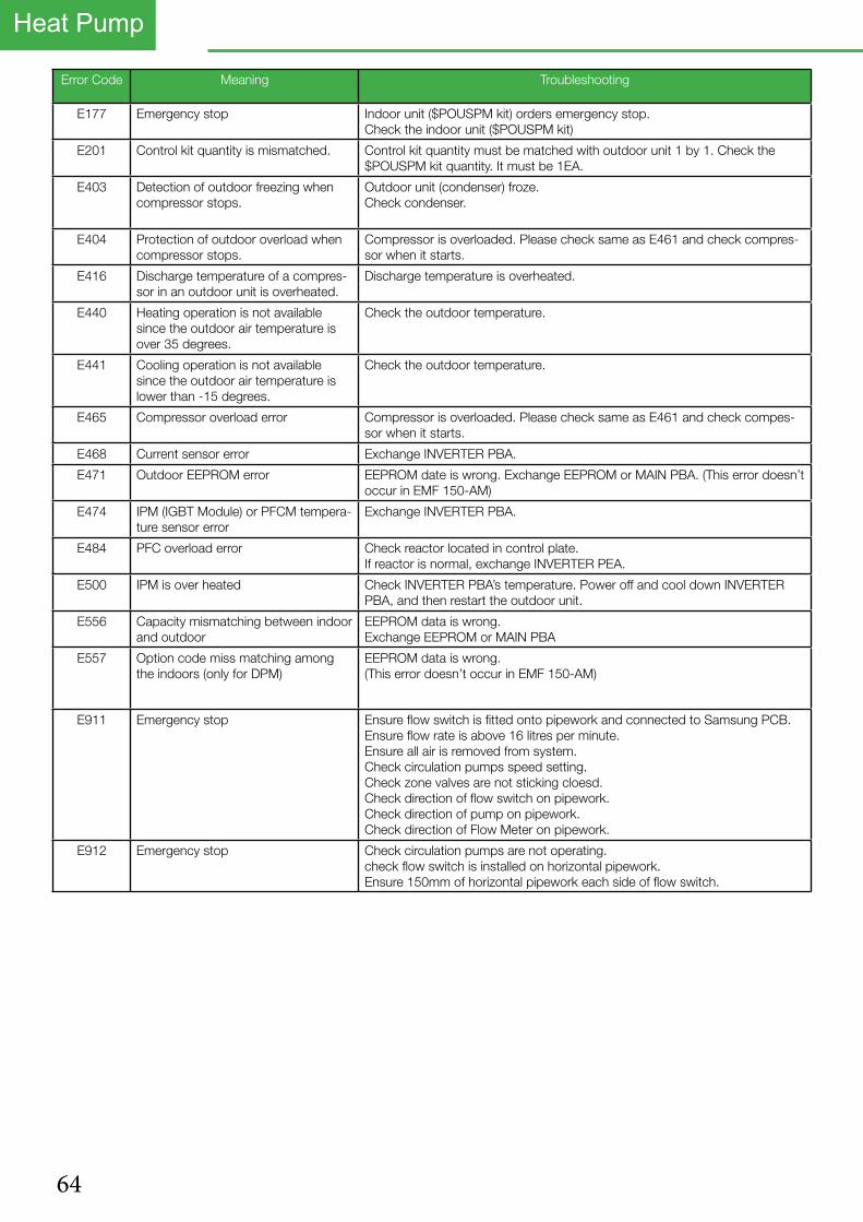
64
Heat Pump
Error Code Meaning Troubleshooting
E177 Emergency stop Indoor unit ($POUSPM kit) orders emergency stop.Check the indoor unit ($POUSPM kit)
E201 Control kit quantity is mismatched. Control kit quantity must be matched with outdoor unit 1 by 1. Check the $POUSPM kit quantity. It must be 1EA.
E403 Detection of outdoor freezing when compressor stops.
Outdoor unit (condenser) froze.Check condenser.
E404 Protection of outdoor overload when compressor stops.
Compressor is overloaded. Please check same as E461 and check compres-sor when it starts.
E416 Discharge temperature of a compres-sor in an outdoor unit is overheated.
Discharge temperature is overheated.
E440 Heating operation is not available since the outdoor air temperature is over 35 degrees.
Check the outdoor temperature.
E441 Cooling operation is not available since the outdoor air temperature is lower than -15 degrees.
Check the outdoor temperature.
E465 Compressor overload error Compressor is overloaded. Please check same as E461 and check compes-sor when it starts.
E468 Current sensor error Exchange INVERTER PBA.
E471 Outdoor EEPROM error EEPROM date is wrong. Exchange EEPROM or MAIN PBA. (This error doesn’t occur in EMF 150-AM)
E474 IPM (IGBT Module) or PFCM tempera-ture sensor error
Exchange INVERTER PBA.
E484 PFC overload error Check reactor located in control plate.If reactor is normal, exchange INVERTER PEA.
E500 IPM is over heated Check INVERTER PBA’s temperature. Power off and cool down INVERTER PBA, and then restart the outdoor unit.
E556 Capacity mismatching between indoor and outdoor
EEPROM data is wrong.Exchange EEPROM or MAIN PBA
E557 Option code miss matching among the indoors (only for DPM)
EEPROM data is wrong.(This error doesn’t occur in EMF 150-AM)
E911 Emergency stop Ensure flow switch is fitted onto pipework and connected to Samsung PCB.Ensure flow rate is above 16 litres per minute.Ensure all air is removed from system.Check circulation pumps speed setting.Check zone valves are not sticking cloesd.Check direction of flow switch on pipework.Check direction of pump on pipework.Check direction of Flow Meter on pipework.
E912 Emergency stop Check circulation pumps are not operating.check flow switch is installed on horizontal pipework.Ensure 150mm of horizontal pipework each side of flow switch.

65
Control Kit EHS Monoblock Wiring
Terminal No. Function Description
A1 230V AC Live Input Mains Power in 6mm² Cable
A2 230AC Neutral Input Mains Power in 6mm² Cable
A3 230V AC Neutral Output Neutral Output to DHW Immersion (2.5mm² - 4mm² cable, depending on length of cable to immersion)
A4 230V AC Live Output Live Output to DHW Immersion (2.5mm² - 4mm² cable, depending on length of cable to immersion)
B1 230V AC Neutral Output Neutral Output to Backup Immersion Contactor or Back Up Boiler (1.5mm² cable)
B2 230V AC Live Output Live Output to Backup immersion Contactor (1.5mm² cable)
B4 230V AC Live Output Live Output to Backup Boiler (1.5mm² cable)
B5 230V AC Neutral Output Neutral Output to Circulation Pump (1.5mm² cable)
B6 230V AC Live Output Live Output to irculation Pump (1.5mm² cable)
B7 230V AC Neutral Output Neutral Output to DHW Zone Valve (Blue Cable on DHw Zone Valve)
B9 230V AC Live Output Live Output to DHW Zone Valve (Brown Cable on DHW Zone Valve)
B11 230V AC Neutral Output Neutral output to Heating Zone Valve (Blue Cable on Heating Zone Valve 1)
B14 230V AC Live Output Live Output to Heating Zone Valve 1 (Brown Cable on Heating Zone Valve 1)
B15 230V AC Live Input Neutral output to Heating Zone Valve 2 (Blue Cable on Heating Zone Valve 2)
B18 230V AC Live Input Live Output to Heating Zone Valve 2 (Brown Cable on Heating Zone Valve 2)
B19 230V AC Neutral Output Neutral Output to Time Clock (1.5mm² cable)
B20 230V AC Live Output Permanent Live to Time Clock (1.5mm² cable)
B22 230V AC Live Input Switch Live back from Time Clock for Heating Zone 1 (1.5mm² cable)
B24 230V AC Live Input Switch Live back from Time Clock for Heating Zone 2 (1.5mm² cable)
V1 12V Input Input from Samsung Commissioning Controller (Wiring Cable provided with Controller)
V2 12V Input Input from Samsung Commissioning Controller (Wiring Cable provided with Controller)
V3 12V Input Input from Samsung Commissioning Controller (Wiring Cable provided with Controller)
V4 12V Input Input from Samsung Commissioning Controller (Wiring Cable provided with Controller)
F1 12V Comms Communication between External Heat Pump and internal PCB (CAT 5 Shielded)
F2 12V Comms Communication between External Heat Pump and internal PCB (CAT 5 Shielded)
Earths Connected to Earth Bar

66
Heat Pump
__________________________________________________________________________________________________________________________________________________________________________________________________________________________________________________________________________________________________________________________________________________________________________________________________________________________________________________________________________________________________________________________________________________________________________________________________________________________________________________________________________________________________________________________________________________________________________________________________________________________________________________________________________________________________________________________________________________________________________________________________________________________________________________________________________________________________________________________________________________________________________________________________________________________________________________________________________________________________________________________________________________________________________________________________________________________________________________________________________________________________________________________________________________________________________________________________________________________________________________________________________________________________________________________________________________________________________________________________________________________________________________________________________________________________________________________________________________________________________________________________________________________________________________________________________________________________________________________________________________________________________________________________________________________________________________________________________________________________________________________________________________________________________________________________________________________________________________________________________________________________________________________________________________________________________________________________________________________________________________________________________________________________________________________________________________________________________________________________________________________________________________________________________________________________________________________________________________________________________________________________________________________________________________________________________________________________________________________________________________________________________________________________________________________________________________________________________________________________________________________________________________________________________________________________________________________________________________________________

67

68
Heat Pump
Kylemore Park West, Ballyfermot, Dublin 10+353 (1) 623 7080 +353 (1) 626 [email protected]
Unit 17C&D Power Road, Plantation Bus. Pk. Bromborough, Wirral, CH62 3RN+44 (0) 1513 551 094+44 (0) 1513 568 [email protected]
23-200 Kraśnik, ul. Towarowa 34.+48 (0) 128811171+48 (0) [email protected]
JOULE IE
JOULE UK
JOULE PL
mail telfaxemlweb
telfaxemlweb
mail telfaxemlweb