Embed Size (px)
Citation preview

Generation IV Nuclear Reactors as a Basis for Future Electricity Production in the World
Professor Igor Pioro1 and Professor Pavel Kirillov2 1Faculty of Energy Systems & Nuclear Science, University of Ontario Institute of Technology, 2000 Simcoe Str. N.,
Oshawa ON L1H 7K4 Canada. E-mail: [email protected] 2State Scientific Centre of the Russian Federation - Institute of Physics and Power Engineering (IPPE) named after A.I.
Leipunsky, Obninsk, Russia. E-mail: [email protected]
Keywords: Electricity generation; nuclear power plant; Generation IV nuclear reactors.
1. Introduction
It is well known that the electrical-power generation is the key factor for advances in any other industries, agriculture and level of living (see Chapter 1) [1]. In general, electrical energy can be generated by: 1) non-renewable-energy sources such as coal, natural gas, oil, and nuclear; and 2) renewable-energy sources such as hydro, wind, solar, biomass, geothermal and marine. However, the main sources for electrical-energy generation are: 1) thermal - primary coal and secondary natural gas; 2) “large” hydro and 3) nuclear. The rest of the energy sources might have visible impact just in some countries. In addition, the renewable-energy sources such as wind and solar are not really reliable sources for industrial power generation, because they depend on Mother nature and relative costs of electrical energy generated by these and some other renewable-energy sources with exception of large hydro-electric power plants can be significantly higher than those generated by non-renewable-energy sources. In general, nuclear power is a non-renewable source as the fossil fuels, but nuclear resources can be used significantly longer than some fossil fuels. Currently, this source of energy is considered as the most viable one for electrical generation for the next 50 – 100 years. Also, NPPs don’t emit carbon dioxide into atmosphere. However, all current and oncoming Generation III+ NPPs are not very competitive with modern thermal power plants in terms of thermal efficiency (for details, see Chapters 2 and 3), the difference in values of thermal efficiencies between thermal and nuclear power plants can be up to 20 – 25%. Therefore, new generation (Generation IV) NPPs with thermal efficiencies close to those of modern thermal power plants, i.e., within a range of 45 – 50% at least, should be designed and built in the nearest future. Therefore, Generation IV NPP concepts will be considered in this chapter.
2. Next generation nuclear power plants
The demand for clean, non-fossil based electricity is growing; therefore, the world needs to develop new nuclear reactors with higher thermal efficiencies in order to increase electricity generation and decrease detrimental effects on the environment. The current fleet of NPPs is classified as Generation II and III (just a limited number of Generation III+ reactors (mainly, Advanced Boiling Water Reactors (ABWRs) operates in some countries). However, all these designs (here we are talking about only water-cooled power reactors) are not as energy efficient as they should be, because their operating temperatures are relatively low, i.e., below 350°C for a reactor coolant and even lower for steam. Currently, a group of countries, including Canada, EU, Japan, Russia, USA and others have initiated an international collaboration to develop the next generation nuclear reactors (Generation IV reactors). The ultimate goal of developing such reactors is an increase in thermal efficiencies of NPPs from 30 - 36% to 45 - 50% and even higher. This increase in thermal efficiency would result in a higher generation of electricity compared to current Light Water Reactor (LWR) technologies per 1 kg of uranium. The Generation IV International Forum (GIF) Program has narrowed design options of nuclear reactors to six concepts. These concepts are: 1) Gas-cooled Fast Reactor (GFR) or just High Temperature Reactor (HTR), 2) Very High Temperature Reactor (VHTR), 3) Sodium-cooled Fast Reactor (SFR), 4) Lead-cooled Fast Reactor (LFR), 5) Molten Salt Reactor (MSR), and 6) SuperCritical Water-cooled Reactor (SCWR). Figures 1 - 10 show schematics of these concepts. These nuclear-reactor concepts differ one from each other in terms of their design, neutron spectrum, coolant, moderator, operating temperatures and pressures. A brief description of each Generation IV nuclear-reactor concept has been provided below. Gas-cooled Fast Reactor (GFR) or High Temperature Reactor (HTR) (see Fig. 1) is a fast-neutron-spectrum reactor, which can be used for the production of electricity and co-generation of hydrogen through thermochemical cycles or high-temperature electrolysis. The coolant is helium with inlet and outlet temperatures of 490 and 850°C, respectively. The net plant efficiency is about 48% with the direct Brayton helium-gas-turbine cycle. Table 1 lists a summary of design parameters for GFR (US DOE, 2002). However, due to some problems with implementation of the direct
Materials and processes for energy: communicating current research and technological developments (A. Méndez-Vilas, Ed.)____________________________________________________________________________________________________
©FORMATEX 2013818

Brayton helium-gas-turbine cycle, the indirect Rankine steam cycle or even indirect supercritical carbon-dioxide Brayton gas-turbine cycle are also considered. The indirect cycles will be linked to the GFR through heat exchangers.
Fig. 1. Gas-cooled Fast Reactor (GFR) NPP concept (US DOE).
Table 1. Key-design parameters of Gas-cooled Fast Reactor (GFR) concept.
Reactor Parameters Unit Reference Value Reactor power MWth 600 Coolant inlet/outlet temperatures °C 490/850 Pressure MPa 9 Coolant massflow rate kg/s 320 Average power density MWth/m
3 100 Reference fuel compound - UPuC/SiC (70/30%) with about 20% Pu Net-plant efficiency % 48
Very High Temperature Reactor (VHTR) (see Fig. 2) is a thermal-neutron-spectrum reactor. The ultimate purpose of this nuclear-reactor design is the co-generation of hydrogen through high-temperature electrolysis. In a VHTR, graphite and helium have been chosen as the moderator and the coolant, respectively. The inlet and outlet temperatures of the coolant are 640 and 1000°C, respectively, at a pressure of 7 MPa (US DOE, 2002). Due to such high outlet temperatures, the thermal efficiency of VHTR will be above 50%. A summary of design parameters of VHTR are listed in Table 2 (US DOE, 2002). In general, the US DOE supports research on several Generation IV reactor concepts http://nuclear.energy.gov/genIV/neGenIV4.html). However, the priority is being given to the VHTR, as a system compatible with advanced electricity production, hydrogen co-generation and high-temperature process-heat applications.
Materials and processes for energy: communicating current research and technological developments (A. Méndez-Vilas, Ed.)____________________________________________________________________________________________________
©FORMATEX 2013 819
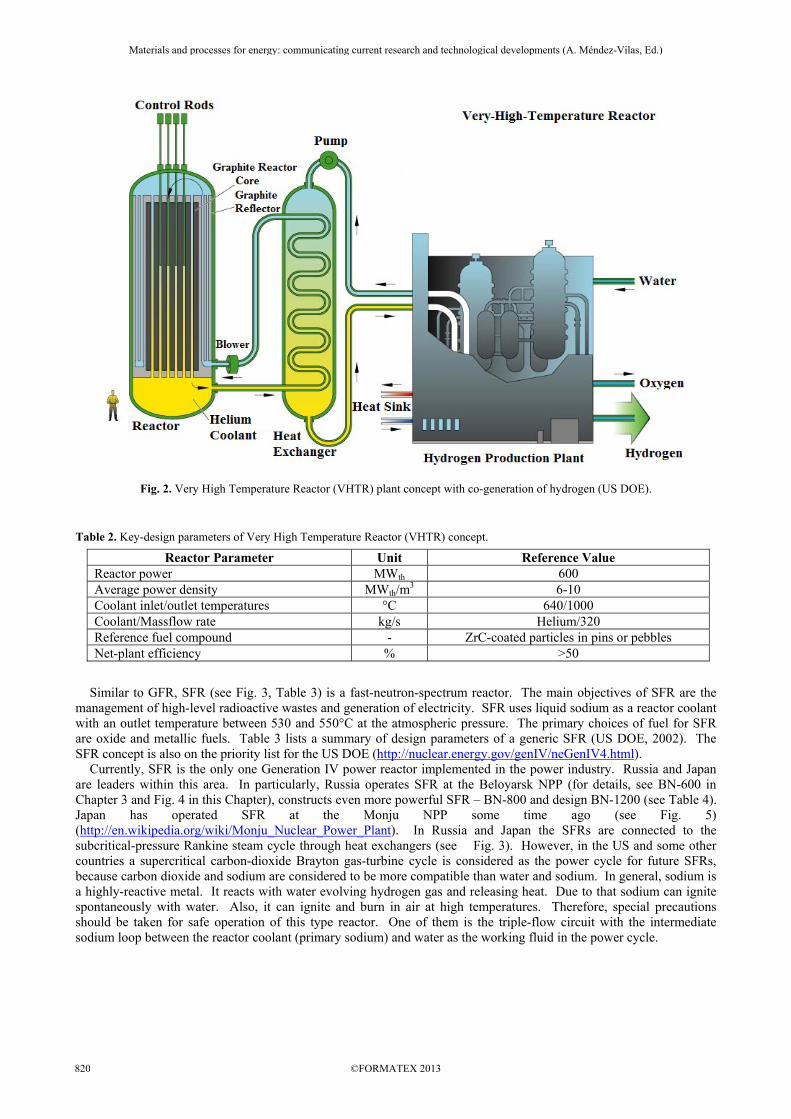
Fig. 2. Very High Temperature Reactor (VHTR) plant concept with co-generation of hydrogen (US DOE).
Table 2. Key-design parameters of Very High Temperature Reactor (VHTR) concept.
Reactor Parameter Unit Reference Value Reactor power MWth 600 Average power density MWth/m
3 6-10 Coolant inlet/outlet temperatures °C 640/1000 Coolant/Massflow rate kg/s Helium/320 Reference fuel compound - ZrC-coated particles in pins or pebbles Net-plant efficiency % >50
Similar to GFR, SFR (see Fig. 3, Table 3) is a fast-neutron-spectrum reactor. The main objectives of SFR are the management of high-level radioactive wastes and generation of electricity. SFR uses liquid sodium as a reactor coolant with an outlet temperature between 530 and 550°C at the atmospheric pressure. The primary choices of fuel for SFR are oxide and metallic fuels. Table 3 lists a summary of design parameters of a generic SFR (US DOE, 2002). The SFR concept is also on the priority list for the US DOE (http://nuclear.energy.gov/genIV/neGenIV4.html). Currently, SFR is the only one Generation IV power reactor implemented in the power industry. Russia and Japan are leaders within this area. In particularly, Russia operates SFR at the Beloyarsk NPP (for details, see BN-600 in Chapter 3 and Fig. 4 in this Chapter), constructs even more powerful SFR – BN-800 and design BN-1200 (see Table 4). Japan has operated SFR at the Monju NPP some time ago (see Fig. 5) (http://en.wikipedia.org/wiki/Monju_Nuclear_Power_Plant). In Russia and Japan the SFRs are connected to the subcritical-pressure Rankine steam cycle through heat exchangers (see Fig. 3). However, in the US and some other countries a supercritical carbon-dioxide Brayton gas-turbine cycle is considered as the power cycle for future SFRs, because carbon dioxide and sodium are considered to be more compatible than water and sodium. In general, sodium is a highly-reactive metal. It reacts with water evolving hydrogen gas and releasing heat. Due to that sodium can ignite spontaneously with water. Also, it can ignite and burn in air at high temperatures. Therefore, special precautions should be taken for safe operation of this type reactor. One of them is the triple-flow circuit with the intermediate sodium loop between the reactor coolant (primary sodium) and water as the working fluid in the power cycle.
Materials and processes for energy: communicating current research and technological developments (A. Méndez-Vilas, Ed.)____________________________________________________________________________________________________
©FORMATEX 2013820

Fig. 3. Sodium Fast Reactor (SFR) NPP concept (US DOE, 2002). Table 3. Key-design parameters of generic SFR concept.
Reactor Parameter Unit Reference Value Reactor power MWth 1000-5000 Thermal efficiency % 40–42% Coolant - Sodium Coolant melting/boiling temperatures °C 98/883 Coolant density at 450°C kg/m3 844 Pressure inside reactor MPa ~0.1 Coolant maximum outlet temperature °C 530-550 Average power density MWth/m
3 350 Reference fuel compound - Oxide or metal alloy Cladding - Ferritic or ODS ferritic Average burnup GWD/MTHM ~150-200
Table 4. Key-design parameters of Russian SFRs (www.proatom.ru).
No. Parameter BN-600* BN-800** BN-1200*** 1 Thermal power, MWth 1470 2100 2800 2 Electrical power, MWel 600 880 1220 3 Basic components:
No of turbines × type No of generators × type
3 × K-200-130
3 × ТГВ-200-M
1 × K-800-130 1 × ТЗВ-800-2
1 × K-1200-160 1 × ТЗВ-1200-2
4 Pressure vessel Diameter, m Height, m
12.86 12.60
12.96 14.82
16.9 20.72
5 No of heat-transfer loops 3 3 4 6 Temperature of reactor coolant: sodium,
primary loop - Tin/Tout, °C 377/550 354/547 410/550
7 Temperature of intermediate coolant: sodium, 328/518 309/505 355/527
Materials and processes for energy: communicating current research and technological developments (A. Méndez-Vilas, Ed.)____________________________________________________________________________________________________
©FORMATEX 2013 821
No. Parameter BN-600* BN-800** BN-1200*** secondary loop - Tin/Tout, °C
8 Temperature of power-cycle working fluid: water/steam - Tin/Tout, °C
240/505 210/490 275/510
9 Pressure at steam-generator outlet, MPa 13.7 14.0 17.0 10 Scheme of steam reheat with Sodium Steam Steam 11 Basic unchangeable components service term,
years 30 40 60
12 NPP thermal efficiency (gross), % 42.5 41.9 43.6 13 NPP thermal efficiency (net), % 40.0 38.8 40.5
* BN-600 – the only one SFR currently in operation in the world; Beloyarsk NPP; commercial start – 1981. ** BN-800 – Beloyarsk NPP, commercial start ~2014. *** BN-1200 – concept of future SFR.
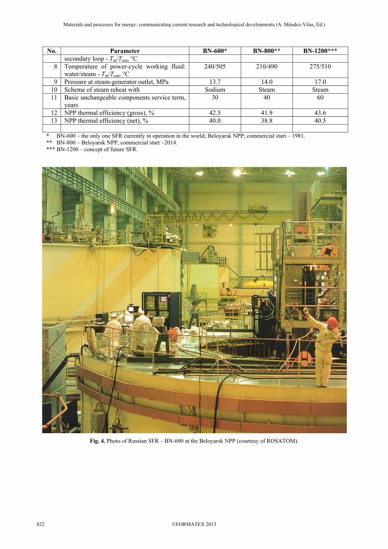
Fig. 4. Photo of Russian SFR – BN-600 at the Beloyarsk NPP (courtesy of ROSATOM).
Materials and processes for energy: communicating current research and technological developments (A. Méndez-Vilas, Ed.)____________________________________________________________________________________________________
©FORMATEX 2013822
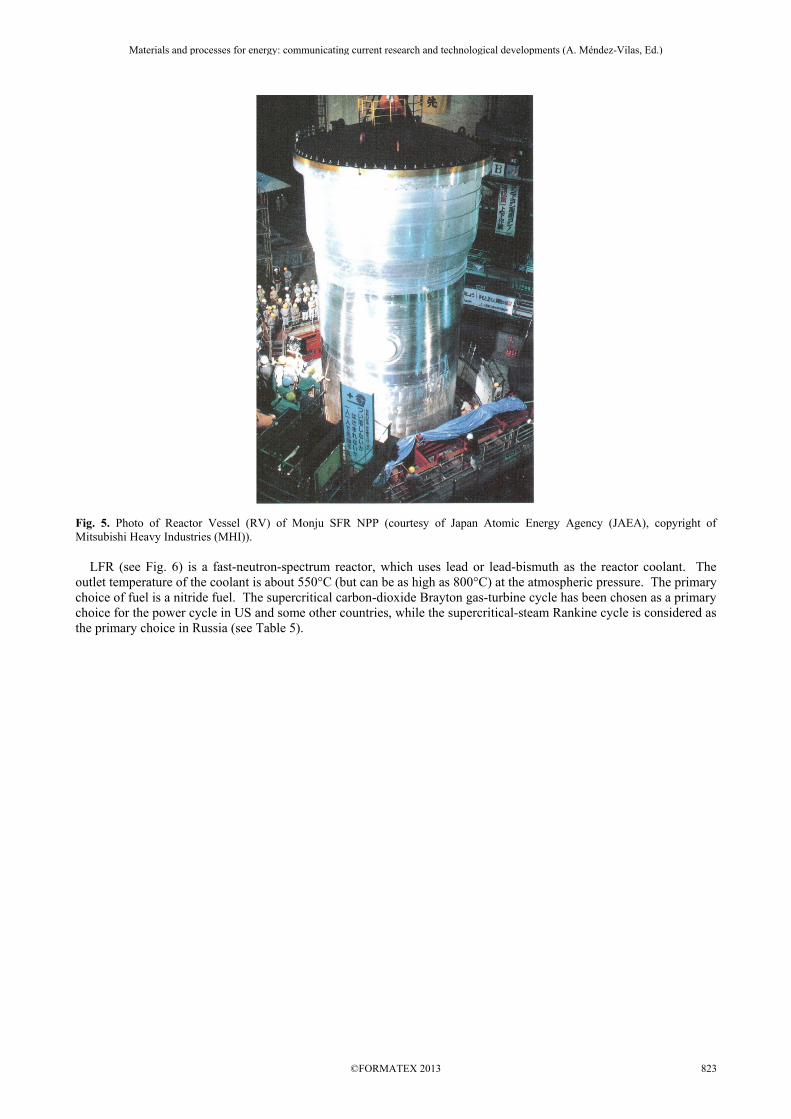
Fig. 5. Photo of Reactor Vessel (RV) of Monju SFR NPP (courtesy of Japan Atomic Energy Agency (JAEA), copyright of Mitsubishi Heavy Industries (MHI)). LFR (see Fig. 6) is a fast-neutron-spectrum reactor, which uses lead or lead-bismuth as the reactor coolant. The outlet temperature of the coolant is about 550°C (but can be as high as 800°C) at the atmospheric pressure. The primary choice of fuel is a nitride fuel. The supercritical carbon-dioxide Brayton gas-turbine cycle has been chosen as a primary choice for the power cycle in US and some other countries, while the supercritical-steam Rankine cycle is considered as the primary choice in Russia (see Table 5).
Materials and processes for energy: communicating current research and technological developments (A. Méndez-Vilas, Ed.)____________________________________________________________________________________________________
©FORMATEX 2013 823

Fig. 6. Lead Fast Reactor (LFR) NPP concept (US DOE). Table 5. Key-design parameters of LFRs planned to be built in Russia (based on NIKIET data).
Reactor Parameter Unit Brest-300 Brest-1200 Reactor power (thermal/electrical) MW 700/300 2800/1200 Thermal efficiency % 43 Primary coolant - Lead Coolant melting/boiling temperatures °C 328/1743 Coolant density at 450°C kg/m3 10,520 Pressure inside reactor MPa ~0.1 Coolant inlet/outlet temperatures °C 420/540 Coolant massflow rate t/s 40 158 Maximum coolant velocity m/s 1.8 1.7 Fuel - UN+PuN Fuel loading t 16 64 Term of fuel inside reactor years 5 5–6 Fuel reloading per year - 1 Core diameter/height m / m 2.3/1.1 4.8/1.1 Number of fuel bundles - 185 332 Fuel-rod diameter mm 9.1; 9.6; 10.4 Fuel-rod pitch mm 13.6 Maximum cladding temperature °C 650 Steam-generator pressure MPa 24.5 Steam-generator inlet/outlet temperatures °C 340/520 Steam-generator capacity t/s 0.43 1.72 Term of reactor years 30 60
Materials and processes for energy: communicating current research and technological developments (A. Méndez-Vilas, Ed.)____________________________________________________________________________________________________
©FORMATEX 2013824
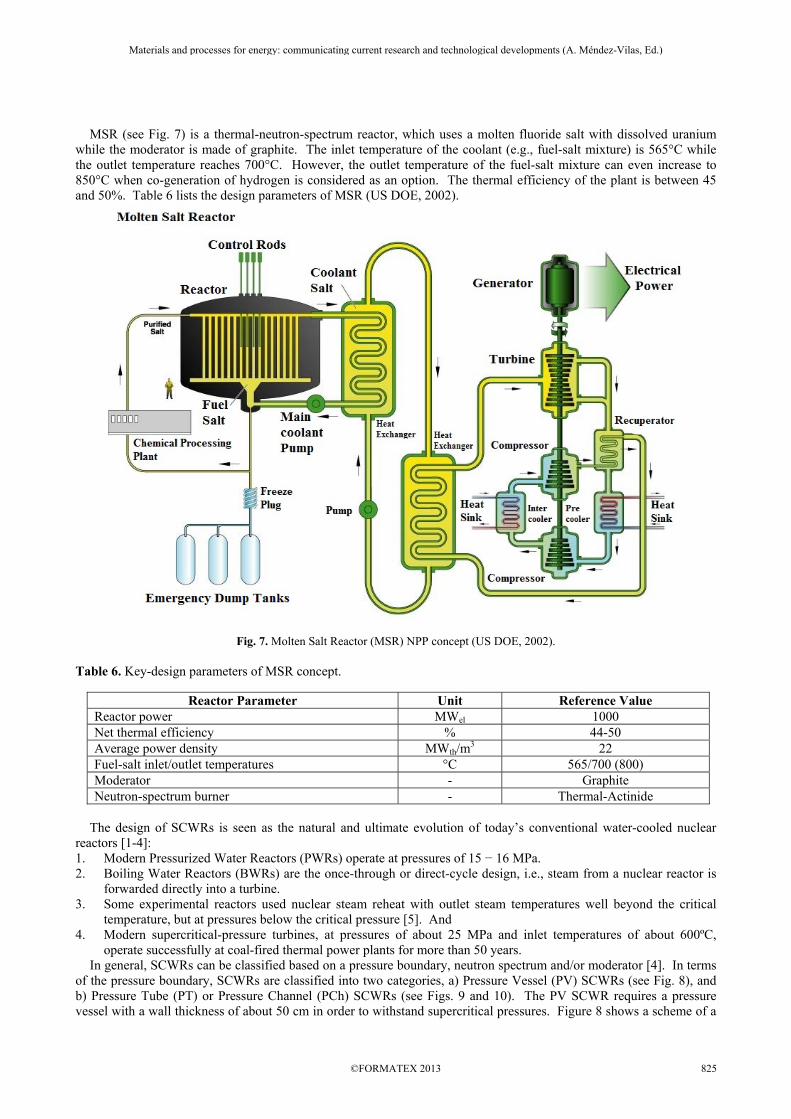
MSR (see Fig. 7) is a thermal-neutron-spectrum reactor, which uses a molten fluoride salt with dissolved uranium while the moderator is made of graphite. The inlet temperature of the coolant (e.g., fuel-salt mixture) is 565°C while the outlet temperature reaches 700°C. However, the outlet temperature of the fuel-salt mixture can even increase to 850°C when co-generation of hydrogen is considered as an option. The thermal efficiency of the plant is between 45 and 50%. Table 6 lists the design parameters of MSR (US DOE, 2002).
Fig. 7. Molten Salt Reactor (MSR) NPP concept (US DOE, 2002). Table 6. Key-design parameters of MSR concept.
Reactor Parameter Unit Reference Value Reactor power MWel 1000 Net thermal efficiency % 44-50 Average power density MWth/m
3 22 Fuel-salt inlet/outlet temperatures °C 565/700 (800) Moderator - Graphite Neutron-spectrum burner - Thermal-Actinide
The design of SCWRs is seen as the natural and ultimate evolution of today’s conventional water-cooled nuclear reactors [1-4]: 1. Modern Pressurized Water Reactors (PWRs) operate at pressures of 15 − 16 MPa. 2. Boiling Water Reactors (BWRs) are the once-through or direct-cycle design, i.e., steam from a nuclear reactor is
forwarded directly into a turbine. 3. Some experimental reactors used nuclear steam reheat with outlet steam temperatures well beyond the critical
temperature, but at pressures below the critical pressure [5]. And 4. Modern supercritical-pressure turbines, at pressures of about 25 MPa and inlet temperatures of about 600ºC,
operate successfully at coal-fired thermal power plants for more than 50 years. In general, SCWRs can be classified based on a pressure boundary, neutron spectrum and/or moderator [4]. In terms of the pressure boundary, SCWRs are classified into two categories, a) Pressure Vessel (PV) SCWRs (see Fig. 8), and b) Pressure Tube (PT) or Pressure Channel (PCh) SCWRs (see Figs. 9 and 10). The PV SCWR requires a pressure vessel with a wall thickness of about 50 cm in order to withstand supercritical pressures. Figure 8 shows a scheme of a
Materials and processes for energy: communicating current research and technological developments (A. Méndez-Vilas, Ed.)____________________________________________________________________________________________________
©FORMATEX 2013 825
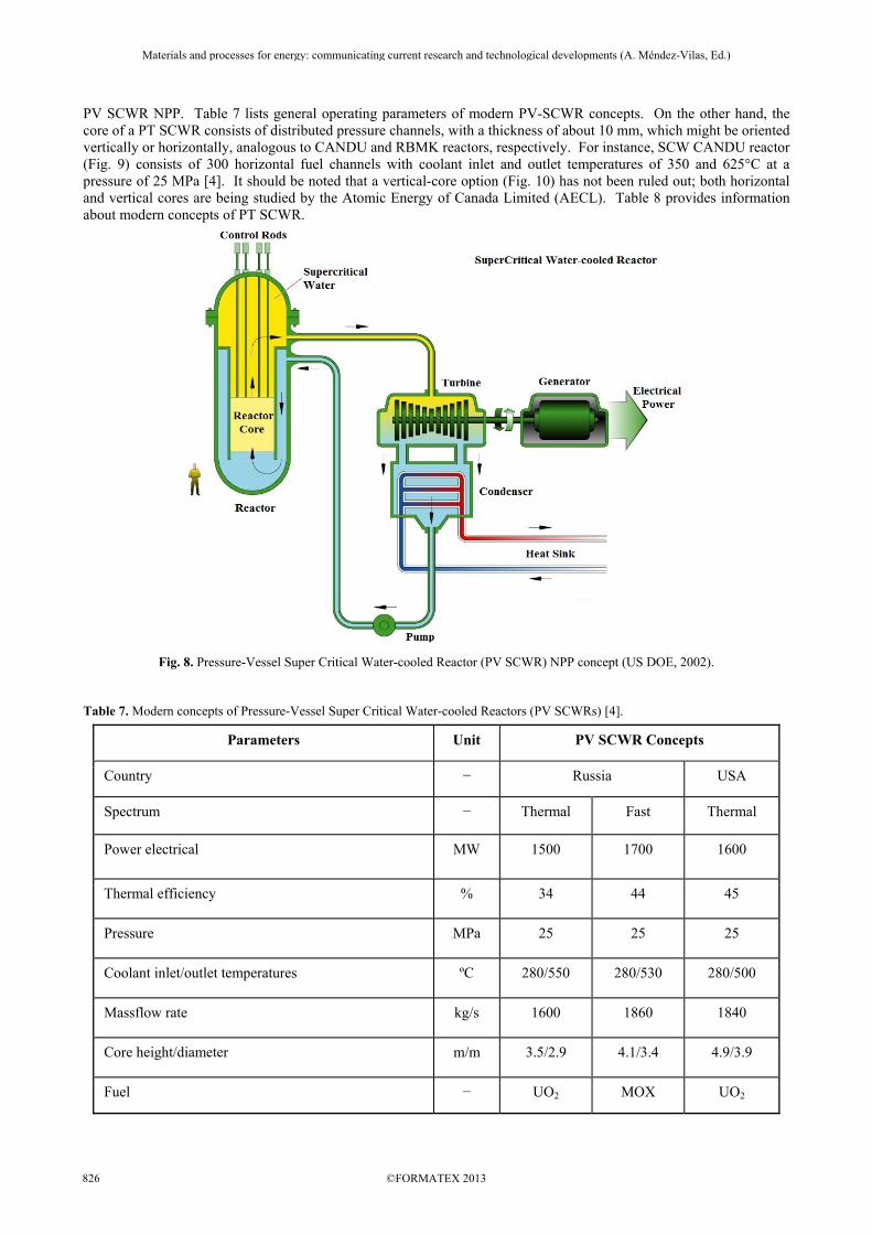
PV SCWR NPP. Table 7 lists general operating parameters of modern PV-SCWR concepts. On the other hand, the core of a PT SCWR consists of distributed pressure channels, with a thickness of about 10 mm, which might be oriented vertically or horizontally, analogous to CANDU and RBMK reactors, respectively. For instance, SCW CANDU reactor (Fig. 9) consists of 300 horizontal fuel channels with coolant inlet and outlet temperatures of 350 and 625°C at a pressure of 25 MPa [4]. It should be noted that a vertical-core option (Fig. 10) has not been ruled out; both horizontal and vertical cores are being studied by the Atomic Energy of Canada Limited (AECL). Table 8 provides information about modern concepts of PT SCWR.
Fig. 8. Pressure-Vessel Super Critical Water-cooled Reactor (PV SCWR) NPP concept (US DOE, 2002). Table 7. Modern concepts of Pressure-Vessel Super Critical Water-cooled Reactors (PV SCWRs) [4].
Parameters Unit PV SCWR Concepts
Country − Russia USA
Spectrum − Thermal Fast Thermal
Power electrical MW 1500 1700 1600
Thermal efficiency % 34 44 45
Pressure MPa 25 25 25
Coolant inlet/outlet temperatures ºC 280/550 280/530 280/500
Massflow rate kg/s 1600 1860 1840
Core height/diameter m/m 3.5/2.9 4.1/3.4 4.9/3.9
Fuel − UO2 MOX UO2
Materials and processes for energy: communicating current research and technological developments (A. Méndez-Vilas, Ed.)____________________________________________________________________________________________________
©FORMATEX 2013826

Parameters Unit PV SCWR Concepts
Enrichment %wt − − 5
Maximum cladding temperature ºC 630 630 −
Moderator − H2O − H2O
T1,P1
T2, P2
T3, P3
T1,P1
T2, P2
T3, P3
T1,P1
T2, P2
T3, P3
H.P. S
CONDENSER
H.P. S
CONDENSER
Brine
Heat for Co-Generation or IP/LP Turbines
Turbine
Pump GeneratorCore
Sustainable Fuel input Electric power Electric power
Hydrogen and process heat Hydrogen and process heat
Drinking water Drinking water
Multiple products are key to sustainable future and competitive designs
Industrial isotopesIndustrial isotopes
H.P
Turbine
Fig. 9. Pressure-Tube (PT) SCW-CANDU-reactor NPP concept (courtesy of Dr. R. Duffey, AECL).
Fig. 10. Vertical core-configuration option of PT SCW-CANDU-reactor concept (courtesy of AECL).
Materials and processes for energy: communicating current research and technological developments (A. Méndez-Vilas, Ed.)____________________________________________________________________________________________________
©FORMATEX 2013 827
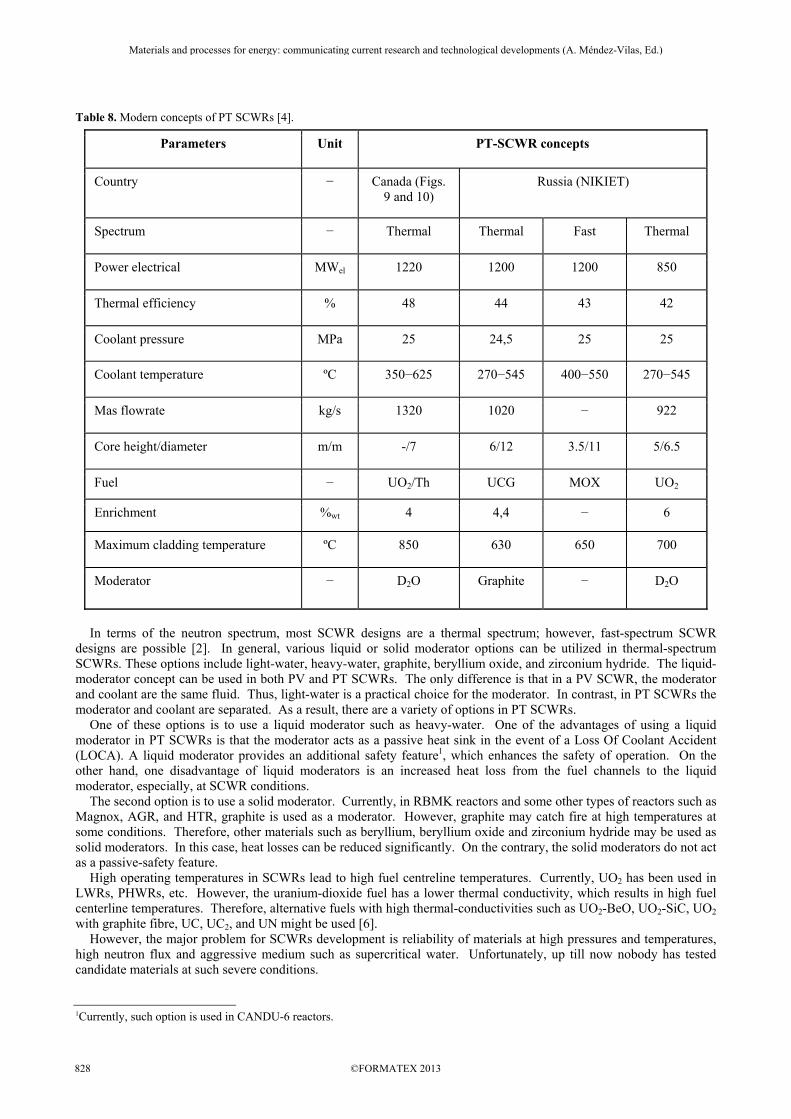
Table 8. Modern concepts of PT SCWRs [4].
Parameters Unit PT-SCWR concepts
Country − Canada (Figs. 9 and 10)
Russia (NIKIET)
Spectrum − Thermal Thermal Fast Thermal
Power electrical MWel 1220 1200 1200 850
Thermal efficiency % 48 44 43 42
Coolant pressure MPa 25 24,5 25 25
Coolant temperature ºC 350−625 270−545 400−550 270−545
Mas flowrate kg/s 1320 1020 − 922
Core height/diameter m/m -/7 6/12 3.5/11 5/6.5
Fuel − UO2/Th UCG MOX UO2
Enrichment %wt 4 4,4 − 6
Maximum cladding temperature ºC 850 630 650 700
Moderator − D2O Graphite − D2O
In terms of the neutron spectrum, most SCWR designs are a thermal spectrum; however, fast-spectrum SCWR designs are possible [2]. In general, various liquid or solid moderator options can be utilized in thermal-spectrum SCWRs. These options include light-water, heavy-water, graphite, beryllium oxide, and zirconium hydride. The liquid-moderator concept can be used in both PV and PT SCWRs. The only difference is that in a PV SCWR, the moderator and coolant are the same fluid. Thus, light-water is a practical choice for the moderator. In contrast, in PT SCWRs the moderator and coolant are separated. As a result, there are a variety of options in PT SCWRs. One of these options is to use a liquid moderator such as heavy-water. One of the advantages of using a liquid moderator in PT SCWRs is that the moderator acts as a passive heat sink in the event of a Loss Of Coolant Accident (LOCA). A liquid moderator provides an additional safety feature1, which enhances the safety of operation. On the other hand, one disadvantage of liquid moderators is an increased heat loss from the fuel channels to the liquid moderator, especially, at SCWR conditions. The second option is to use a solid moderator. Currently, in RBMK reactors and some other types of reactors such as Magnox, AGR, and HTR, graphite is used as a moderator. However, graphite may catch fire at high temperatures at some conditions. Therefore, other materials such as beryllium, beryllium oxide and zirconium hydride may be used as solid moderators. In this case, heat losses can be reduced significantly. On the contrary, the solid moderators do not act as a passive-safety feature. High operating temperatures in SCWRs lead to high fuel centreline temperatures. Currently, UO2 has been used in LWRs, PHWRs, etc. However, the uranium-dioxide fuel has a lower thermal conductivity, which results in high fuel centerline temperatures. Therefore, alternative fuels with high thermal-conductivities such as UO2-BeO, UO2-SiC, UO2 with graphite fibre, UC, UC2, and UN might be used [6]. However, the major problem for SCWRs development is reliability of materials at high pressures and temperatures, high neutron flux and aggressive medium such as supercritical water. Unfortunately, up till now nobody has tested candidate materials at such severe conditions.
1Currently, such option is used in CANDU-6 reactors.
Materials and processes for energy: communicating current research and technological developments (A. Méndez-Vilas, Ed.)____________________________________________________________________________________________________
©FORMATEX 2013828
3. Conclusions
1. Major sources for electrical-energy production in the world are: 1) thermal - primary coal and secondary natural gas; 2) “large” hydro and 3) nuclear.
2. Nuclear power is, in general, a non-renewable source as the fossil fuels, but nuclear resources can be used significantly longer than some fossil fuels. Currently, this source of energy is considered as the most viable one for electrical generation for the next 50 – 100 years. Also, NPPs don’t emit carbon dioxide into atmosphere, but create radioactive wastes.
3. In general, the major driving force for all advances in thermal and nuclear power plants is thermal efficiency. Ranges of gross thermal efficiencies of modern power plants are as the following: 1) Combined-cycle thermal power plants – up to 62%; 2) Supercritical-pressure coal-fired thermal power plants – up to 55%; 3) Carbon-dioxide-cooled reactor NPPs – up to 42%; 4) Sodium-cooled fast reactor NPP – up to 40%; and 5) Modern water-cooled reactors – 30 – 36%.
4. Therefore, all current and oncoming Generation III+ NPPs are not very competitive with modern thermal power plants in terms of thermal efficiency, the difference in values of thermal efficiencies between thermal and nuclear power plants can be up to 20 – 25%. Therefore, new generation (Generation IV) NPPs with thermal efficiencies close to those of modern thermal power plants, i.e., within a range of 45 – 50% at least, should be designed and built in the nearest future. Also, the problem with reprocessing and ultimate safe storage of nuclear wastes should be resolved.
5. The Generation IV International Forum (GIF) Program has narrowed design options of nuclear reactors to six concepts. These concepts are: 1) Gas-cooled Fast Reactor (GFR) or just High Temperature Reactor (HTR), 2) Very High Temperature Reactor (VHTR), 3) Sodium-cooled Fast Reactor (SFR), 4) Lead-cooled Fast Reactor (LFR), 5) Molten Salt Reactor (MSR), and 6) SuperCritical Water-cooled Reactor (SCWR).
4. Nomenclature
T temperature, ºC Subscripts el electrical in inlet out outlet th thermal Abbreviations: ABWR Advanced Boiling Water Reactor AECL Atomic Energy of Canada Limited AGR Advanced Gas-cooled Reactor BN Fast Neutrons (reactor) (in Russian abbreviation) BWR Boiling Water Reactor CANDU CANada Deuterium Uranium DOE Department Of Energy (USA) EU European Union GFR Gas Fast Reactor HTR High Temperature Reactor LFR Lead-cooled Fast Reactor LMFBR Liquid-Metal Fast-Breeder Reactor MOX Mixed OXides MSR Molten Salt Reactor NIKIET Research and Development Institute of Power Engineering (in Russian abbreviations) or RDIPE, Moscow,
Russia NPP Nuclear Power Plant PCh Pressure Channel PT Pressure Tube PV Pressure Vessel PWR Pressurized Water Reactor RBMK Reactor of Large Capacity Channel type (in Russian abbreviations) SCWR SuperCritical Water Reactor SFR Sodium Fast Reactor USA United States of America VHTR Very High Temperature Reactor
Materials and processes for energy: communicating current research and technological developments (A. Méndez-Vilas, Ed.)____________________________________________________________________________________________________
©FORMATEX 2013 829
References [1] Schulenberg, Th. and Starflinger, J., Editors, 2012. High Performance Light Water Reactor. Design and Analyses, KIT
Scientific Publishing, Germany, 241 pages. [2] Oka, Yo., Koshizuka, S., Ishiwatari, Y. and Yamaji, A., 2010. Super Light Water Reactors and Super Fast Reactors, Springer,
416 pages. [3] Pioro, I., 2011. The Potential Use of Supercritical Water-Cooling in Nuclear Reactors. Chapter in Nuclear Energy
Encyclopedia: Science, Technology, and Applications, Editors: S.B. Krivit, J.H. Lehr and Th.B. Kingery, J. Wiley & Sons, Hoboken, NJ, USA, pp. 309-347 pages.
[4] Pioro, I.L. and Duffey, R.B., 2007. Heat Transfer and Hydraulic Resistance at Supercritical Pressures in Power Engineering Applications, ASME Press, New York, NY, USA, 328 pages.
[5] Saltanov, Eu. and Pioro, I., 2011. World Experience in Nuclear Steam Reheat, Chapter in book “Nuclear Power: Operation, Safety and Environment”, Editor: P.V. Tsvetkov, INTECH, Rijeka, Croatia, pp. 3-28.
[6] Peiman, W., Pioro, I. and Gabriel, K., 2012. Thermal Aspects of Conventional and Alternative Fuels in SuperCritical Water-Cooled Reactor (SCWR) Applications, Chapter in book “Nuclear Reactors”, Editor A.Z. Mesquita, INTECH, Rijeka, Croatia, pp. 123-156.
Materials and processes for energy: communicating current research and technological developments (A. Méndez-Vilas, Ed.)____________________________________________________________________________________________________
©FORMATEX 2013830