Embed Size (px)
Citation preview

Relion® 670 series
Generator protection REG670 2.0Product guide
Contents
1. Application..................................................................... 3
2. Available functions..........................................................7
3. Differential protection....................................................16
4. Impedance protection.................................................. 18
5. Current protection........................................................ 20
6. Voltage protection........................................................ 23
7. Frequency protection....................................................24
8. Multipurpose protection................................................25
9. Secondary system supervision..................................... 26
10. Control........................................................................ 26
11. Logic...........................................................................28
12. Monitoring...................................................................29
13. Metering......................................................................31
14. Human machine interface............................................31
15. Basic IED functions..................................................... 31
16. Station communication ...............................................32
17. Remote communication.............................................. 32
18. Hardware description.................................................. 33
19. Connection diagrams.................................................. 36
20. Technical data.............................................................37
21. Ordering for customized IED......................................100
22. Ordering for pre-configured IED.................................109
23. Ordering for Accessories........................................... 113
Disclaimer
The information in this document is subject to change without notice and should not be construed as a commitment by ABB. ABB assumes no responsibility for any errors
that may appear in this document. Drawings and diagrams are not binding.
© Copyright 2014 ABB.
All rights reserved.
Trademarks
ABB and Relion are registered trademarks of the ABB Group. All other brand or product names mentioned in this document may be trademarks or registered trademarks
of their respective holders.
Generator protection REG670 2.0 1MRK502054-BEN D
Product version: 2.0
2 ABB

1. ApplicationThe REG670 is used for protection, control and monitoring ofgenerators and generator-transformer blocks from relativelysmall units up to the largest generating units. The IED has acomprehensive function library, covering the requirements formost generator applications. The large number of analog inputsavailable enables, together with the large functional library,integration of many functions in one IED. In typical applicationstwo IED units can provide total functionality, also providing ahigh degree of redundancy. REG670 can as well be used forprotection and control of shunt reactors.
Stator earth fault protection, both traditional 95% as well as100% injection and 3rd harmonic based are included. When theinjection based protection is used, 100% of the machine statorwinding, including the star point, is protected under alloperating modes. The 3rd harmonic based 100% stator earthfault protection uses 3rd harmonic differential voltage principle.Injection based 100% stator earth fault protection can operateeven when machine is at standstill. Well proven algorithms forpole slip, underexcitation, rotor earth fault, negative sequencecurrent protections, and so on, are included in the IED.
The generator differential protection in the REG670 adapted tooperate correctly for generator applications where factors aslong DC time constants and requirement on short trip time havebeen considered.
As many of the protection functions can be used as multipleinstances there are possibilities to protect more than one object
in one IED. It is possible to have protection for an auxiliarypower transformer integrated in the same IED having mainprotections for the generator. The concept thus enables verycost effective solutions.
The REG670 also enables valuable monitoring possibilities asmany of the process values can be transferred to an operatorHMI.
The wide application flexibility makes this product an excellentchoice for both new installations and for refurbishment inexisting power plants.
Communication via optical connections ensures immunityagainst disturbances.
By using patented algorithm REG670 (or any other productfrom 670 series) can track the power system frequency in quitewide range from 9Hz to 95Hz (for 50Hz power system). In orderto do that preferably the three-phase voltage signal from thegenerator terminals shall be connected to the IED. Then IED canadopt its filtering algorithm in order to properly measurephasors of all current and voltage signals connected to the IED.This feature is essential for proper operation of the protectionduring generator start-up and shut-down procedure.
REG670 can be used in applications with the IEC 61850-9-2LEprocess bus with up to six merging units (MU) depending on theother functionality included in the IED.
Generator protection REG670 2.0 1MRK502054-BEN D
Product version: 2.0 Issued: July 2016Revision: D
ABB 3

Description of configuration A20
G
SA PTUF
81U f<
SA PTUF
81 f<
SA PTOF
81O f>
SA PTOF
81 f>
UV2 PTUV
27 2(3U<)
OV2 PTOV
59 2(3U>)
VN MMXU
MET UN
V MSQI
MET Usqi
CC RBRF
50BF 3I>BF
FUF SPVC
U>/I<
GOP PDOP
32 P>
GUP PDUP
37 P<
TR PTTR
49 θ>
NS2 PTOC
46 I2>
C MMXU
MET I
GEN PDIF
87G 3Id/I>
ZGV PDIS
21 Z<CV GAPC
64R Re<
CV GAPC
2(i>/U<)
LEX PDIS
40 Φ <
DRP RDRE
DFR/SER DR
OEX PVPH
24 U/f>
ETP MMTR
MET W/Varh
CV MMXN
MET P/Q
+
RXTTE4
REG670 A20 – Generator differential + backup protection 12AI (7I + 5U)
YY
ROV2 PTOV
59N 2(U0>)
AEG PVOC
50AE U/I>
SMP PTRC
94 1
ROV2 PTOV
59N 2(U0>)
V MMXU
MET U
GEN_QA1
GEN_TRM_VT
GEN_TRM_CT
ROT_INJ_VT
ROT_INJ_CT
GEN_SP_CT
GEN_SP_VT
OC4 PTOC
51_67 4(3I>)
C MSQI
MET Isqi
C MMXU
MET I
SES RSYN
25 SC/VC
CCS SPVC
87 INd/I
S SIML
71
ROTI PHIZ
64R R<
OOS PPAM
78 Ucos
HZ PDIF
87 Id>
SDE PSDE
67N IN>
T2W PDIF
87T 3Id/I>
STEF PHIZ
59THD U3d/N
EF4 PTOC
51N_67N 4(IN>)
SA PFRC
81 df/dt<>
Other Functions available from the function library
Optional Functions
STTI PHIZ
64S R<
NS4 PTOC
46I2 4(I2>)
PSP PPAM
78 Ucos
CC PDSC
52PD PD
PH PIOC
50 3I>>
EF PIOC
50N IN>>
VDC PTOV
60 Ud>
Q CBAY
3 Control
S SIMG
63
GR PTTR
49R θ>
TCM YLTC
84 ↑↓
VD SPVC
60 Ud>
GS PTTR
49S θ>
FTA QFVR
81A f<>
VR PVOC
51V 2(I>/U<)
Q CRSV
3 Control
S CILO
3 Control
S CSWI
3 Control
S SCBR
Control
S XSWI
3 Control
S XCBR
3 Control
IEC11000068-3-en.vsd
IEC11000068 V4 EN
Figure 1. Typical generator protection application with generator differential and back-up protection, including 12 analog inputs transformersin half 19" case size.
Generator protection REG670 2.0 1MRK502054-BEN D
Product version: 2.0
4 ABB
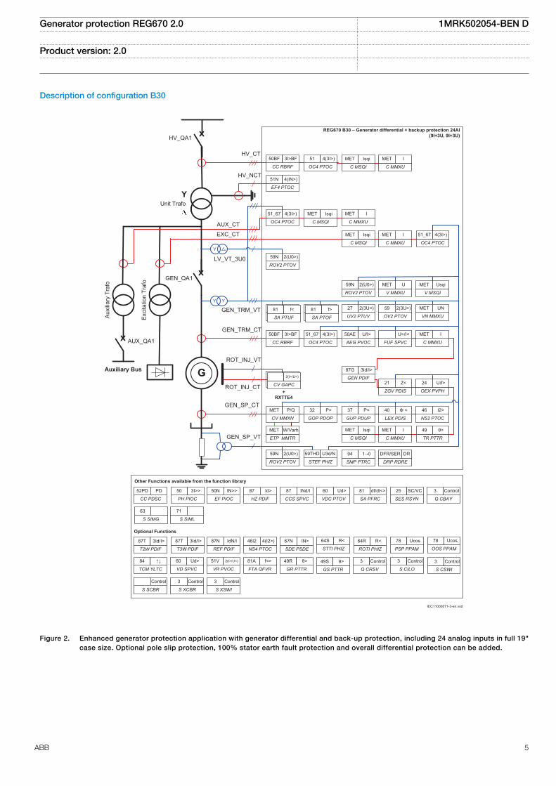
Description of configuration B30
Auxiliary Bus
YUnit Trafo
AuxiliaryTrafo
ExcitationTrafo
CC RBRF
50BF 3I>BF
EF4 PTOC
51N 4(IN>)
ROV2 PTOV
59N 2(U0>)
SA PTUF
81U f<
SA PTUF
81 f<
SA PTOF
81O f>
SA PTOF
81 f>
UV2 PTUV
27 2(3U<)
OV2 PTOV
59 2(3U>)
V MSQI
MET Usqi
V MMXU
MET U
CC RBRF
50BF 3I>BF
FUF SPVC
U>/I<
ROV2 PTOV
59N 2(U0>)
GOP PDOP
32 P>
GUP PDUP
37 P<
TR PTTR
49 θ>
NS2 PTOC
46 I2>
C MMXU
MET I
GEN PDIF
87G 3Id/I>
ZGV PDIS
21 Z<CV GAPC
64R Re<
CV GAPC
2(I>/U<)
REG670 B30 – Generator differential + backup protection 24AI
(9I+3U, 9I+3U)
LEX PDIS
40 Φ <
DRP RDRE
DFR/SER DR
OEX PVPH
24 U/f>
ETP MMTR
MET W/Varh
CV MMXN
MET P/Q
+
RXTTE4
AEG PVOC
50AE U/I>
ROV2 PTOV
59N 2(U0>)
VN MMXU
MET UN
STEF PHIZ
59THD U3d/N
SMP PTRC
94 1
OC4 PTOC
51_67 4(3I>)
GEN_QA1
AUX_QA1
HV_QA1
HV_CT
LV_VT_3U0
GEN_TRM_VT
GEN_TRM_CT
GEN_SP_CT
GEN_SP_VT
OC4 PTOC
51_67 4(3I>)
ROT_INJ_VT
ROT_INJ_CT
AUX_CT
EXC_CT
HV_NCT
Y
Y Y
G
OC4 PTOC
51 4(3I>)
C MSQI
MET Isqi
C MMXU
MET I
C MSQI
MET Isqi
C MMXU
MET I
C MSQI
MET Isqi
C MMXU
MET I
C MSQI
MET Isqi
C MMXU
MET I
OC4 PTOC
51_67 4(3I>)
SES RSYN
25 SC/VC
CCS SPVC
87 INd/I
STTI PHIZ
64S R<
OOS PPAM
78 Ucos
T3W PDIF
87T 3Id/I>
REF PDIF
87N IdN/I
T2W PDIF
87T 3Id/I>
ROTI PHIZ
64R R<
HZ PDIF
87 Id>
SA PFRC
81 df/dt<>
Other Functions available from the function library
Optional Functions
SDE PSDE
67N IN>
NS4 PTOC
46I2 4(I2>)
PSP PPAM
78 Ucos
CC PDSC
52PD PD
PH PIOC
50 3I>>
EF PIOC
50N IN>>
VDC PTOV
60 Ud>
Q CBAY
3 Control
S SIMG
63
S SIML
71
GR PTTR
49R θ>
TCM YLTC
84 ↑↓
VD SPVC
60 Ud>
GS PTTR
49S θ>
FTA QFVR
81A f<>
VR PVOC
51V 2(I>/U<)
Q CRSV
3 Control
S CILO
3 Control
S CSWI
3 Control
S SCBR
Control
S XSWI
3 Control
S XCBR
3 Control
IEC11000071-3-en.vsd
IEC11000071 V4 EN
Figure 2. Enhanced generator protection application with generator differential and back-up protection, including 24 analog inputs in full 19"case size. Optional pole slip protection, 100% stator earth fault protection and overall differential protection can be added.
Generator protection REG670 2.0 1MRK502054-BEN D
Product version: 2.0
ABB 5
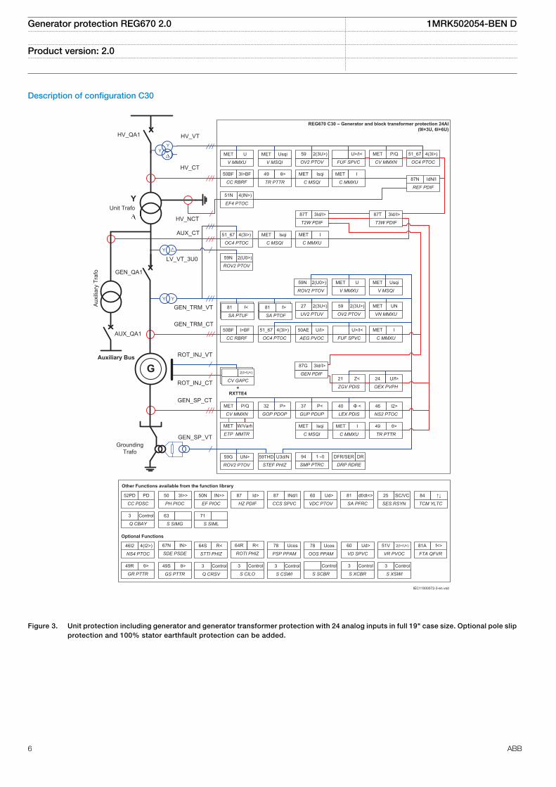
Description of configuration C30
Auxiliary Bus
YUnit Trafo
AuxiliaryTrafo
CC RBRF
50BF 3I>BF
ROV2 PTOV
59N 2(U0>)
SA PTUF
81U f<
SA PTUF
81 f<
SA PTOF
81O f>
SA PTOF
81 f>
UV2 PTUV
27 2(3U<)
OV2 PTOV
59 2(3U>)
V MMXU
MET U
VN MMXU
MET UN
V MSQI
MET Usqi
CC RBRF
50BF I>BF
FUF SPVC
U>/I<
ROV2 PTOV
59G UN>
GOP PDOP
32 P>
GUP PDUP
37 P<
TR PTTR
49 θ>
NS2 PTOC
46 I2>
C MMXU
MET I
GEN PDIF
87G 3Id/I>
ZGV PDIS
21 Z<CV GAPC
64R Re<
CV GAPC
2(I>/U<)
YY
TR PTTR
49 θ>
OV2 PTOV
59 2(3U>)
CV MMXN
MET P/Q
FUF SPVC
U>/I<
LEX PDIS
40 Φ <
ETP MMTR
MET W/Varh
CV MMXN
MET P/Q
Grounding
Trafo
OEX PVPH
24 U/f>
DRP RDRE
DFR/SER DR
+
RXTTE4
AEG PVOC
50AE U/I>
T2W PDIF
87T 3Id/I>
REG670 C30 – Generator and block transformer protection 24AI
(9I+3U, 6I+6U)
51N
EF4 PTOC
4(IN>)
STEF PHIZ
59THD U3d/N
OC4 PTOC
51_67 4(3I>)
SMP PTRC
94 1
HV_QA1
AUX_QA1
GEN_QA1
HV_VT
HV_CT
LV_VT_3U0
AUX_CT
GEN_TRM_VT
GEN_TRM_CT
ROT_INJ_CT
ROT_INJ_VT
GEN_SP_CT
GEN_SP_VT
REF PDIF
87N IdN/I
OC4 PTOC
51_67 4(3I>)
OC4 PTOC
51_67 4(3I>)
Y
Y Y
ROV2 PTOV
59N 2(U0>)
HV_NCT
G
C MSQI
MET Isqi
C MMXU
MET I
V MMXU
MET U
V MSQI
MET Usqi
C MSQI
MET Isqi
C MMXU
MET I
C MSQI
MET Isqi
C MMXU
MET I
T3W PDIF
87T 3Id/I>
SES RSYN
25 SC/VC
CCS SPVC
87 INd/I
STTI PHIZ
64S R<
OOS PPAM
78 Ucos
ROTI PHIZ
64R R<
HZ PDIF
87 Id>
SA PFRC
81 df/dt<>
Other Functions available from the function library
Optional Functions
SDE PSDE
67N IN>
NS4 PTOC
46I2 4(I2>)
PSP PPAM
78 Ucos
CC PDSC
52PD PD
PH PIOC
50 3I>>
EF PIOC
50N IN>>
VDC PTOV
60 Ud>
TCM YLTC
84 ↑↓
S SIMG
63
S SIML
71
GR PTTR
49R θ>
Q CBAY
3 Control
GS PTTR
49S θ>
Q CRSV
3 Control
S CILO
3 Control
S CSWI
3 Control
S SCBR
Control
S XSWI
3 Control
S XCBR
3 Control
VD SPVC
60 Ud>
FTA QFVR
81A f<>
VR PVOC
51V 2(I>/U<)
IEC11000072-3-en.vsd
IEC11000072 V4 EN
Figure 3. Unit protection including generator and generator transformer protection with 24 analog inputs in full 19" case size. Optional pole slipprotection and 100% stator earthfault protection can be added.
Generator protection REG670 2.0 1MRK502054-BEN D
Product version: 2.0
6 ABB
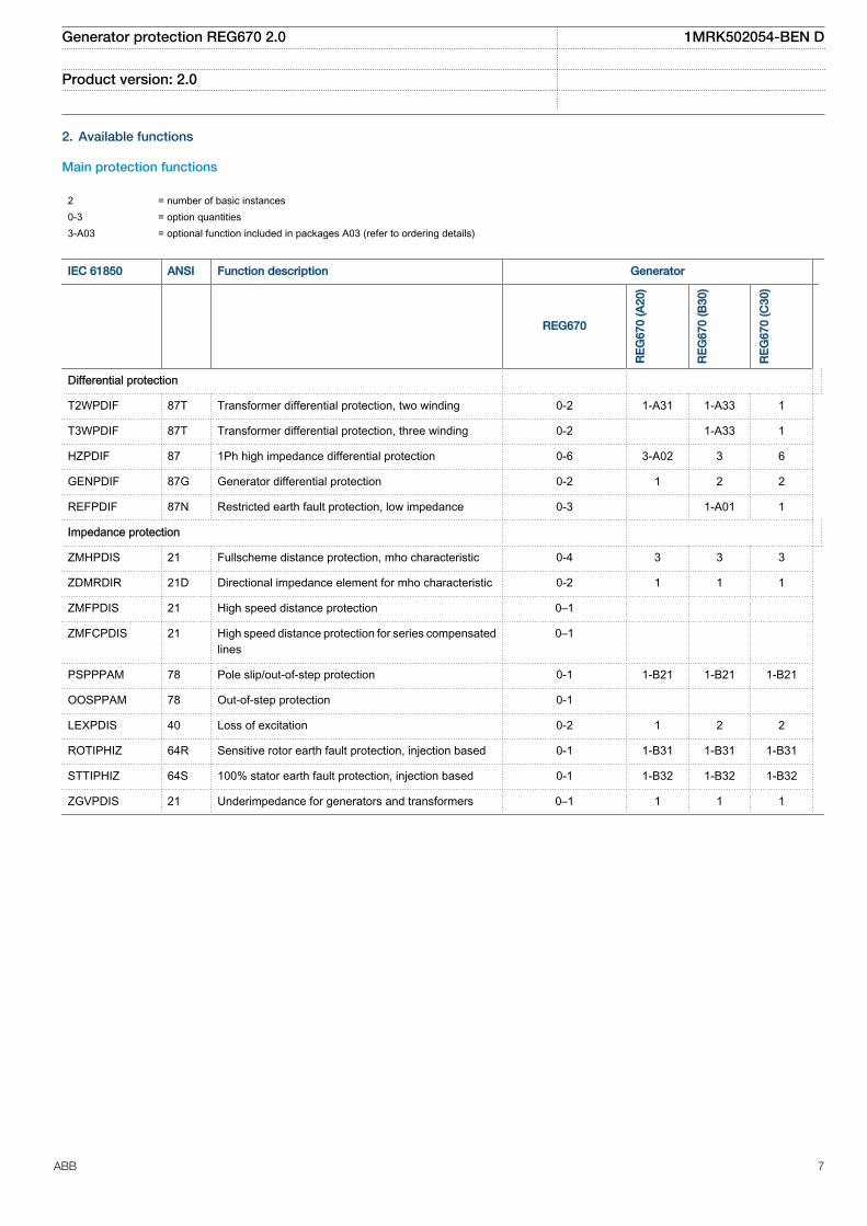
2. Available functions
Main protection functions
2 = number of basic instances0-3 = option quantities3-A03 = optional function included in packages A03 (refer to ordering details)
IEC 61850 ANSI Function description Generator
REG670
RE
G67
0 (A
20)
RE
G67
0 (B
30)
RE
G67
0 (C
30)
Differential protection
T2WPDIF 87T Transformer differential protection, two winding 0-2 1-A31 1-A33 1
T3WPDIF 87T Transformer differential protection, three winding 0-2 1-A33 1
HZPDIF 87 1Ph high impedance differential protection 0-6 3-A02 3 6
GENPDIF 87G Generator differential protection 0-2 1 2 2
REFPDIF 87N Restricted earth fault protection, low impedance 0-3 1-A01 1
Impedance protection
ZMHPDIS 21 Fullscheme distance protection, mho characteristic 0-4 3 3 3
ZDMRDIR 21D Directional impedance element for mho characteristic 0-2 1 1 1
ZMFPDIS 21 High speed distance protection 0–1
ZMFCPDIS 21 High speed distance protection for series compensatedlines
0–1
PSPPPAM 78 Pole slip/out-of-step protection 0-1 1-B21 1-B21 1-B21
OOSPPAM 78 Out-of-step protection 0-1
LEXPDIS 40 Loss of excitation 0-2 1 2 2
ROTIPHIZ 64R Sensitive rotor earth fault protection, injection based 0-1 1-B31 1-B31 1-B31
STTIPHIZ 64S 100% stator earth fault protection, injection based 0-1 1-B32 1-B32 1-B32
ZGVPDIS 21 Underimpedance for generators and transformers 0–1 1 1 1
Generator protection REG670 2.0 1MRK502054-BEN D
Product version: 2.0
ABB 7

Back-up protection functions
IEC 61850 ANSI Function description Generator
REG670
RE
G67
0 (A
20)
RE
G67
0 (B
30)
RE
G67
0 (C
30)
Current protection
PHPIOC 50 Instantaneous phase overcurrent protection 0-4 1 2 2
OC4PTOC 51_671) Four step phase overcurrent protection 0-6 4 4 4
EFPIOC 50N Instantaneous residual overcurrent protection 0-2 1 2 2
EF4PTOC 51N67N2)
Four step residual overcurrent protection 0-6 1 5 5
NS4PTOC 46I2 Four step directional negative phase sequenceovercurrent protection
0-2 1-C41 2-C42 2-C42
SDEPSDE 67N Sensitive directional residual overcurrent and powerprotection
0-2 1-C16 1-C16 1-C16
TRPTTR 49 Thermal overload protection, two time constant 0-3 1 2 3
CCRBRF 50BF Breaker failure protection 0-4 2 4 4
CCPDSC 52PD Pole discordance protection 0-4 2 2 2
GUPPDUP 37 Directional underpower protection 0-4 2 4 4
GOPPDOP 32 Directional overpower protection 0-4 2 4 4
NS2PTOC 46I2 Negative sequence time overcurrent protection formachines
0-2 1 1 1
AEGPVOC 50AE Accidental energizing protection for synchronousgenerator
0-2 1 1 1
VRPVOC 51V Voltage restrained overcurrent protection 0-3 3-C36 3-C36 3-C36
GSPTTR 49S Stator overload protection 0-1 1-C37 1-C37 1-C37
GRPTTR 49R Rotor overload protection 0–1 1-C38 1-C38 1-C38
Voltage protection
UV2PTUV 27 Two step undervoltage protection 0-2 2 2 2
OV2PTOV 59 Two step overvoltage protection 0-2 2 2 2
ROV2PTOV 59N Two step residual overvoltage protection 0-3 3 3 3
OEXPVPH 24 Overexcitation protection 0-2 1 1 2
VDCPTOV 60 Voltage differential protection 0-2 2 2 2
STEFPHIZ 59THD 100% stator earth fault protection, 3rd harmonic based 0-1 1-D21 1 1
Frequency protection
SAPTUF 81 Underfrequency protection 0-6 3 6 6
SAPTOF 81 Overfrequency protection 0-6 3 6 6
SAPFRC 81 Rate-of-change frequency protection 0-3 1 3 3
FTAQFVR 81A Frequency time accumulation protection 0-12 12-E03 12-E03 12-E03
Generator protection REG670 2.0 1MRK502054-BEN D
Product version: 2.0
8 ABB

IEC 61850 ANSI Function description Generator
REG670
RE
G67
0 (A
20)
RE
G67
0 (B
30)
RE
G67
0 (C
30)
Multipurpose protection
CVGAPC General current and voltage protection 1-12 6 6 6
General calculation
SMAIHPAC Multipurpose filter 0-6
1) 67 requires voltage2) 67N requires voltage
Generator protection REG670 2.0 1MRK502054-BEN D
Product version: 2.0
ABB 9
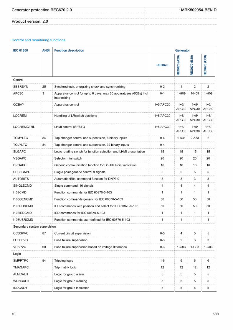
Control and monitoring functions
IEC 61850 ANSI Function description Generator
REG670
RE
G67
0 (A
20)
RE
G67
0 (B
30)
RE
G67
0 (C
30)
Control
SESRSYN 25 Synchrocheck, energizing check and synchronizing 0-2 1 2 2
APC30 3 Apparatus control for up to 6 bays, max 30 apparatuses (6CBs) incl.interlocking
0-1 1-H09 1-H09 1-H09
QCBAY Apparatus control 1+5/APC30 1+5/APC30
1+5/APC30
1+5/APC30
LOCREM Handling of LRswitch positions 1+5/APC30 1+5/APC30
1+5/APC30
1+5/APC30
LOCREMCTRL LHMI control of PSTO 1+5/APC30 1+5/APC30
1+5/APC30
1+5/APC30
TCMYLTC 84 Tap changer control and supervision, 6 binary inputs 0-4 1-A31 2-A33 2
TCLYLTC 84 Tap changer control and supervision, 32 binary inputs 0-4
SLGAPC Logic rotating switch for function selection and LHMI presentation 15 15 15 15
VSGAPC Selector mini switch 20 20 20 20
DPGAPC Generic communication function for Double Point indication 16 16 16 16
SPC8GAPC Single point generic control 8 signals 5 5 5 5
AUTOBITS AutomationBits, command function for DNP3.0 3 3 3 3
SINGLECMD Single command, 16 signals 4 4 4 4
I103CMD Function commands for IEC 60870-5-103 1 1 1 1
I103GENCMD Function commands generic for IEC 60870-5-103 50 50 50 50
I103POSCMD IED commands with position and select for IEC 60870-5-103 50 50 50 50
I103IEDCMD IED commands for IEC 60870-5-103 1 1 1 1
I103USRCMD Function commands user defined for IEC 60870-5-103 1 1 1 1
Secondary system supervision
CCSSPVC 87 Current circuit supervision 0-5 4 5 5
FUFSPVC Fuse failure supervision 0-3 2 3 3
VDSPVC 60 Fuse failure supervision based on voltage difference 0-3 1-G03 1-G03 1-G03
Logic
SMPPTRC 94 Tripping logic 1-6 6 6 6
TMAGAPC Trip matrix logic 12 12 12 12
ALMCALH Logic for group alarm 5 5 5 5
WRNCALH Logic for group warning 5 5 5 5
INDCALH Logic for group indication 5 5 5 5
Generator protection REG670 2.0 1MRK502054-BEN D
Product version: 2.0
10 ABB

IEC 61850 ANSI Function description Generator
REG670
RE
G67
0 (A
20)
RE
G67
0 (B
30)
RE
G67
0 (C
30)
AND, OR, INV,PULSETIMER,GATE,TIMERSET, XOR,LLD,SRMEMORY,RSMEMORY
Configurable logic blocks 40-280 40-280 40-280 40-280
ANDQT, ORQT,INVERTERQT,XORQT,SRMEMORYQT,RSMEMORYQT,TIMERSETQT,PULSETIMERQT,INVALIDQT,INDCOMBSPQT,INDEXTSPQT
Configurable logic blocks Q/T 0–1
SLGAPC,VSGAPC, AND,OR,PULSETIMER,GATE,TIMERSET, XOR,LLD,SRMEMORY, INV
Extension logic package 0–1
FXDSIGN Fixed signal function block 1 1 1 1
B16I Boolean 16 to Integer conversion 18 18 18 18
BTIGAPC Boolean 16 to Integer conversion with Logic Node representation 16 16 16 16
IB16 Integer to Boolean 16 conversion 18 18 18 18
ITBGAPC Integer to Boolean 16 conversion with Logic Node representation 16 16 16 16
TIGAPC Delay on timer with input signal integration 30 30 30 30
TEIGAPC Elapsed time integrator with limit transgression and overflowsupervision
12 12 12 12
Monitoring
CVMMXN,CMMXU,VMMXU, CMSQI,VMSQI, VNMMXU
Measurements 6 6 6 6
AISVBAS Function block for service value presentation of secondary analoginputs
1 1 1 1
EVENT Event function 20 20 20 20
Generator protection REG670 2.0 1MRK502054-BEN D
Product version: 2.0
ABB 11

IEC 61850 ANSI Function description Generator
REG670
RE
G67
0 (A
20)
RE
G67
0 (B
30)
RE
G67
0 (C
30)
DRPRDRE,A1RADR,A2RADR,A3RADR,A4RADR,B1RBDR,B2RBDR,B3RBDR,B4RBDR,B5RBDR,B6RBDR
Disturbance report 1 1 1 1
SPGAPC Generic communication function for Single Point indication 64 64 64 64
SP16GAPC Generic communication function for Single Point indication 16 inputs 16 16 16 16
MVGAPC Generic communication function for Measured Value 24 24 24 24
BINSTATREP Logical signal status report 3 3 3 3
RANGE_XP Measured value expander block 66 66 66 66
SSIMG 63 Gas medium supervision 21 21 21 21
SSIML 71 Liquid medium supervision 3 3 3 3
SSCBR Circuit breaker monitoring 0-4 2-M12 4-M14 4-M14
I103MEAS Measurands for IEC 60870-5-103 1 1 1 1
I103MEASUSR Measurands user defined signals for IEC 60870-5-103 3 3 3 3
I103AR Function status auto-recloser for IEC 60870-5-103 1 1 1 1
I103EF Function status earth-fault for IEC 60870-5-103 1 1 1 1
I103FLTPROT Function status fault protection for IEC 60870-5-103 1 1 1 1
I103IED IED status for IEC 60870-5-103 1 1 1 1
I103SUPERV Supervison status for IEC 60870-5-103 1 1 1 1
I103USRDEF Status for user defiend signals for IEC 60870-5-103 20 20 20 20
L4UFCNT Event counter with limit supervision 30 30 30 30
Metering
PCFCNT Pulse-counter logic 16 16 16 16
ETPMMTR Function for energy calculation and demand handling 6 6 6 6
Generator protection REG670 2.0 1MRK502054-BEN D
Product version: 2.0
12 ABB

Communication
IEC 61850 ANSI Function description Generator
REG670
RE
G67
0 (A
20)
RE
G67
0 (B
30)
RE
G67
0 (C
30)
Station communication
LONSPA, SPA SPA communication protocol 1 1 1 1
ADE LON communication protocol 1 1 1 1
HORZCOMM Network variables via LON 1 1 1 1
PROTOCOL Operation selection between SPA and IEC60870-5-103 for SLM
1 1 1 1
RS485PROT Operation selection for RS485 1 1 1 1
RS485GEN RS485 1 1 1 1
DNPGEN DNP3.0 communication general protocol 1 1 1 1
DNPGENTCP DNP3.0 communication general TCP protocol 1 1 1 1
CHSERRS485 DNP3.0 for EIA-485 communication protocol 1 1 1 1
CH1TCP,CH2TCP,CH3TCP,CH4TCP
DNP3.0 for TCP/IP communication protocol 1 1 1 1
CHSEROPT DNP3.0 for TCP/IP and EIA-485 communicationprotocol
1 1 1 1
MST1TCP,MST2TCP,MST3TCP,MST4TCP
DNP3.0 for serial communication protocol 1 1 1 1
DNPFREC DNP3.0 fault records for TCP/IP and EIA-485communication protocol
1 1 1 1
IEC61850-8-1 Parameter setting function for IEC 61850 1 1 1 1
GOOSEINTLKRCV
Horizontal communication via GOOSE for interlocking 59 59 59 59
GOOSEBINRCV Goose binary receive 16 16 16 16
GOOSEDPRCV GOOSE function block to receive a double point value 64 64 64 64
GOOSEINTRCV GOOSE function block to receive an integer value 32 32 32 32
GOOSEMVRCV GOOSE function block to receive a measurand value 60 60 60 60
GOOSESPRCV GOOSE function block to receive a single point value 64 64 64 64
MULTICMDRCV,MULTICMDSND
Multiple command and transmit 60/10 60/10 60/10 60/10
FRONT, LANABI,LANAB, LANCDI,LANCD
Ethernet configuration of links 1 1 1 1
GATEWAY Ethernet configuration of link one 1 1 1 1
OPTICAL103 IEC 60870-5-103 Optical serial communication 1 1 1 1
Generator protection REG670 2.0 1MRK502054-BEN D
Product version: 2.0
ABB 13

IEC 61850 ANSI Function description Generator
REG670
RE
G67
0 (A
20)
RE
G67
0 (B
30)
RE
G67
0 (C
30)
RS485103 IEC 60870-5-103 serial communication for RS485 1 1 1 1
AGSAL Generic security application component 1 1 1 1
LD0LLN0 IEC 61850 LD0 LLN0 1 1 1 1
SYSLLN0 IEC 61850 SYS LLN0 1 1 1 1
LPHD Physical device information 1 1 1 1
PCMACCS IED Configuration Protocol 1 1 1 1
SECALARM Component for mapping security events on protocolssuch as DNP3 and IEC103
1 1 1 1
FSTACCS Field service tool access via SPA protocol overethernet communication
1 1 1 1
ACTIVLOG Activity logging parameters 1 1 1 1
ALTRK Service Tracking 1 1 1 1
SINGLELCCH Single ethernet port link status 1 1 1 1
PRPSTATUS Dual ethernet port link status 1 1 1 1
PRP IEC 62439-3 parallel redundancy protocol (only in F00) 0-1 1-P03 1-P03 1-P03
Remote communication
Binary signal transfer receive/transmit 6/36 6/36 6/36 6/36
Transmission of analog data from LDCM 1 1 1 1
Receive binary status from remote LDCM 6/3/3 6/3/3 6/3/3 6/3/3
Generator protection REG670 2.0 1MRK502054-BEN D
Product version: 2.0
14 ABB

Basic IED functions
Table 1. Basic IED functions
IEC 61850 or functionname
Description
INTERRSIG Self supervision with internal event list
SELFSUPEVLST Self supervision with internal event list
TIMESYNCHGEN Time synchronization module
SYNCHBIN,SYNCHCAN,SYNCHCMPPS,SYNCHLON,SYNCHPPH,SYNCHPPS,SYNCHSNTP,SYNCHSPA,SYNCHCMPPS
Time synchronization
TIMEZONE Time synchronization
DSTBEGIN,DSTENABLE, DSTEND
GPS time synchronization module
IRIG-B Time synchronization
SETGRPS Number of setting groups
ACTVGRP Parameter setting groups
TESTMODE Test mode functionality
CHNGLCK Change lock function
SMBI Signal matrix for binary inputs
SMBO Signal matrix for binary outputs
SMMI Signal matrix for mA inputs
SMAI1 - SMAI20 Signal matrix for analog inputs
3PHSUM Summation block 3 phase
ATHSTAT Authority status
ATHCHCK Authority check
AUTHMAN Authority management
FTPACCS FTP access with password
SPACOMMMAP SPA communication mapping
SPATD Date and time via SPA protocol
DOSFRNT Denial of service, frame rate control for front port
DOSLANAB Denial of service, frame rate control for OEM port AB
DOSLANCD Denial of service, frame rate control for OEM port CD
DOSSCKT Denial of service, socket flow control
GBASVAL Global base values for settings
PRIMVAL Primary system values
ALTMS Time master supervision
ALTIM Time management
Generator protection REG670 2.0 1MRK502054-BEN D
Product version: 2.0
ABB 15

Table 1. Basic IED functions, continued
IEC 61850 or functionname
Description
ALTRK Service tracking
ACTIVLOG Activity logging parameters
FSTACCS Field service tool access via SPA protocol over ethernet communication
PCMACCS IED Configuration Protocol
SECALARM Component for mapping security events on protocols such as DNP3 and IEC103
DNPGEN DNP3.0 communication general protocol
DNPGENTCP DNP3.0 communication general TCP protocol
CHSEROPT DNP3.0 for TCP/IP and EIA-485 communication protocol
MSTSER DNP3.0 for serial communication protocol
OPTICAL103 IEC 60870-5-103 Optical serial communication
RS485103 IEC 60870-5-103 serial communication for RS485
IEC61850-8-1 Parameter setting function for IEC 61850
HORZCOMM Network variables via LON
LONSPA SPA communication protocol
LEDGEN General LED indication part for LHMI
3. Differential protection
Generator differential protection GENPDIFShort circuit between the phases of the stator windings causesnormally very large fault currents. The short circuit gives risk ofdamages on insulation, windings and stator iron core. The largeshort circuit currents cause large forces, which can causedamage even to other components in the power plant, such asturbine and generator-turbine shaft.
To limit the damage due to stator winding short circuits, thefault clearance must be as fast as possible (instantaneous). Ifthe generator block is connected to the power system close toother generating blocks, the fast fault clearance is essential tomaintain the transient stability of the non-faulted generators.
Normally, the short circuit fault current is very large, that is,significantly larger than the generator rated current. There is arisk that a short circuit can occur between phases close to theneutral point of the generator, thus causing a relatively smallfault current. The fault current can also be limited due to lowexcitation of the generator. Therefore, it is desired that thedetection of generator phase-to-phase short circuits shall berelatively sensitive, detecting small fault currents.
It is also of great importance that the generator differentialprotection does not trip for external faults, with large faultcurrents flowing from the generator.
To combine fast fault clearance, as well as sensitivity andselectivity, the generator differential protection is normally thebest choice for phase-to-phase generator short circuits.
Generator differential protection GENPDIF is also well suited forprotection of shunt reactors or small busduct.
Transformer differential protection T2WPDIF/T3WPDIFThe Transformer differential protection, two-winding T2WPDIFand Transformer differential protection, three-windingT3WPDIF are provided with internal CT ratio matching, vectorgroup compensation and settable zero sequence currentelimination.
The function can be provided with up to six three-phase sets ofcurrent inputs. All current inputs are provided with percentagebias restraint features, making the IED suitable for two- orthree-winding transformer in multi-breaker stationarrangements.
Generator protection REG670 2.0 1MRK502054-BEN D
Product version: 2.0
16 ABB

Two-winding applications
xx05000048.vsd
IEC05000048 V1 EN
two-winding powertransformer
xx05000049.vsd
IEC05000049 V1 EN
two-winding powertransformer withunconnected deltatertiary winding
xx05000050.vsd
IEC05000050 V1 EN
two-winding powertransformer with twocircuit breakers andtwo CT-sets on oneside
xx05000051.vsd
IEC05000051 V1 EN
two-winding powertransformer with twocircuit breakers andtwo CT-sets on bothsides
Three-winding applications
xx05000052.vsd
IEC05000052 V1 EN
three-winding powertransformer with allthree windingsconnected
xx05000053.vsd
IEC05000053 V1 EN
three-winding powertransformer with twocircuit breakers andtwo CT-sets on oneside
xx05000057.vsd
IEC05000057 V1 EN
Autotransformer withtwo circuit breakersand two CT-sets ontwo out of three sides
Figure 4. CT group arrangement fordifferential protection
The setting facilities cover the application of the differentialprotection to all types of power transformers and auto-transformers with or without load tap changer as well as shunt
reactors and local feeders within the station. An adaptivestabilizing feature is included for heavy through-faultcurrents.By introducing the load tap changer position, thedifferential protection pick-up can be set to optimum sensitivitythus covering internal faults with low fault current level.
Stabilization is included for inrush and overexcitation currentsrespectively, cross-blocking is also available. Adaptivestabilization is also included for system recovery inrush and CTsaturation during external faults. A high set unrestraineddifferential current protection element is included for a very highspeed tripping at high internal fault currents.
Included is an sensitive differential protection element based onthe theory of negative sequence current component. Thiselement offers the best possible coverage of power transformerwindings turn to turn faults.
1Ph High impedance differential protection HZPDIFThe 1Ph High impedance differential protection HZPDIFfunctions can be used when the involved CT cores have thesame turns ratio and similar magnetizing characteristics. Itutilizes an external CT secondary current summation by wiring.Actually all CT secondary circuits which are involved in thedifferential scheme are connected in parallel. External seriesresistor, and a voltage dependent resistor which are bothmounted externally to the IED, are also required.
The external resistor unit shall be ordered under IEDaccessories in the Product Guide.
HZPDIF can be used to protect generator stator windings, tee-feeders or busbars, reactors, motors, auto-transformers,capacitor banks and so on. One such function block is used fora high-impedance restricted earth fault protection. Three suchfunction blocks are used to form three-phase, phase-segregated differential protection. Several function blockinstances (for example, six) can be available in a single IED.
Restricted earth-fault protection, low impedance REFPDIFRestricted earth-fault protection, low-impedance functionREFPDIF can be used on all directly or low-impedance earthedwindings. The REFPDIF function provides high sensitivity andhigh speed tripping as it protects each winding separately andthus does not need inrush stabilization.
The REFPDIF function is a percentage biased function with anadditional zero sequence current directional comparisoncriterion. This gives excellent sensitivity and stability duringthrough faults.
REFPDIF can also protect autotransformers. Five currents aremeasured at the most complicated configuration as shown inFigure 5.
Generator protection REG670 2.0 1MRK502054-BEN D
Product version: 2.0
ABB 17

The most typicalapplication
YNdx
dCB
CT
CT
CB Y
IED
CB CB
CB CB
Autotransformer
The most complicatedapplication - autotransformer
CT CT
CT CT
IEC05000058-2-en.vsd
IEC05000058-2 V1 EN
Figure 5. Examples of applications of the REFPDIF
4. Impedance protection
Full-scheme distance measuring, Mho characteristicZMHPDISThe numerical mho line distance protection is a four zone fullscheme protection for back-up detection of short circuit andearth faults.
The full scheme technique provides back-up protection ofpower lines with high sensitivity and low requirement on remoteend communication.
The four zones have fully independent measuring and settings,which gives high flexibility for all types of lines.
Built-in selectable zone timer logic is also provided in thefunction.
The function can be used as under impedance back-upprotection for transformers and generators.
Directional impedance element for Mho characteristicZDMRDIRThe phase-to-earth impedance elements can be optionallysupervised by a phase unselective directional function (phaseunselective, because it is based on symmetrical components).
Distance zones quad with high speed distance protectionZMFPDISThe High speed distance protection (ZMFPDIS) is providingsub-cycle, down towards half-cycle, operate time for basicfaults within 60% of the line length and up to around SIR 5. Atthe same time, it is specifically designed for extra care duringdifficult conditions in high voltage transmission networks, likefaults on long heavily loaded lines and faults generating heavilydistorted signals. These faults are handled with outmostsecurity and dependability, although sometimes with reducedoperating speed.
The ZMFPDIS function is a six zone full scheme protection withthree fault loops for phase-to-phase faults and three fault loops
for phase-to-earth faults for each of the independent zones,which makes the function suitable in applications with single-phase autoreclosing.
The zones can operate independently of each other indirectional (forward or reverse) or non-directional mode.However, zone1 and zone2 is designed to measure in forwarddirection only, while one zone (ZRV) is designed to measure inthe reverse direction. This makes them suitable, together with acommunication scheme, for protection of power lines andcables in complex network configurations, such as parallellines, multi-terminal lines, and so on.
A new built-in adaptive load compensation algorithm preventsoverreaching of the distance zones in the load exporting endduring phase-to-earth faults on heavily loaded power lines. Italso reduces underreach in the importing end.
The ZMFPDIS function-block itself incorporates a phase-selection element and a directional element, contrary toprevious designs in the 670-series, where these elements wererepresented with separate function-blocks.
The operation of the phase-selection element is primarily basedon current change criteria (i.e. delta quantities), withsignificantly increased dependability. There is also a phaseselection criterion operating in parallel which bases itsoperation only on voltage and current phasors.
The directional element utilizes a set of well-establishedquantities to provide fast and correct directional decision duringvarious power system operating conditions, including close-inthree-phase faults, simultaneous faults and faults with onlyzero-sequence in-feed.
Distance zones quad with high speed distance for seriescompensated networks ZMFCPDISHigh speed distance protection (ZMFCPDIS) provides sub-cycle, down towards half-cycle, operate time for basic faultswithin 60% of the line length and up to around SIR 5. At thesame time, it is specifically designed for extra care duringdifficult conditions in high voltage transmission networks, likefaults on long heavily loaded lines and faults generating heavilydistorted signals. These faults are handled with outmostsecurity and dependability, although sometimes with reducedoperating speed.
High speed distance protection ZMFCPDIS is fundamentallythe same function as ZMFPDIS but provides more flexibility inzone settings to suit more complex applications, such as seriescompensated lines. In operation for series compensatednetworks, the parameters of the directional function are alteredto handle voltage reversal.
The ZMFCPDIS function is a six-zone full scheme protectionwith three fault loops for phase-to-phase faults and three faultloops for phase-to-earth faults for each of the independentzones, which makes the function suitable in applications withsingle-phase autoreclosing.
Generator protection REG670 2.0 1MRK502054-BEN D
Product version: 2.0
18 ABB

The zones can operate independently of each other indirectional (forward or reverse) or non-directional mode. Thismakes them suitable, together with a communication scheme,for protection of power lines and cables in complex networkconfigurations, such as parallel lines, multi-terminal lines, andso on.
A new built-in adaptive load compensation algorithm preventsoverreaching of the distance zones in the load exporting endduring phase-to-earth faults on heavily loaded power lines. Italso reduces underreach in the importing end.
The ZMFCPDIS function block incorporates a phase-selectionelement and a directional element, contrary to previous designsin the 670–series, where these elements were represented withseparate function blocks.
The operation of the phase-selection element is primarily basedon current change criteria, with significant increaseddependability. Naturally, there is also a part operating withcontinuous criteria that operates in parallel
The directional element utilizes a set of well-establishedquantities to provide fast and correct directional evaluationduring various conditions, including close-in three-phase faults,simultaneous faults and faults with only zero-sequence in-feed.
Pole slip protection PSPPPAMThe situation with pole slip of a generator can be caused bydifferent reasons.
A short circuit may occur in the external power grid, close to thegenerator. If the fault clearing time is too long, the generator willaccelerate so much, that the synchronism cannot bemaintained.
Undamped oscillations occur in the power system, wheregenerator groups at different locations, oscillate against eachother. If the connection between the generators is too weak themagnitude of the oscillations will increase until the angularstability is lost.
The operation of a generator having pole slip will give risk ofdamages to the generator, shaft and turbine.
• At each pole slip there will be significant torque impact onthe generator-turbine shaft.
• In asynchronous operation there will be induction ofcurrents in parts of the generator normally not carryingcurrent, thus resulting in increased heating. Theconsequence can be damages on insulation and stator/rotor iron.
The Pole slip protection (PSPPPAM) function shall detect poleslip conditions and trip the generator as fast as possible if thelocus of the measured impedance is inside the generator-transformer block. If the centre of pole slip is outside in thepower grid, the first action should be to split the network intotwo parts, after line protection action. If this fails there should be
operation of the generator PSPPPAM in zone 2, to preventfurther damages to the generator, shaft and turbine.
Out-of-step protection OOSPPAMThe out-of-step protection OOSPPAM function in the IED canbe used for both generator protection and as well for lineprotection applications.
The main purpose of the OOSPPAM function is to detect,evaluate, and take the required action during pole slippingoccurrences in the power system.
The OOSPPAM function detects pole slip conditions and tripsthe generator as fast as possible, after the first pole-slip if thecenter of oscillation is found to be in zone 1, which normallyincludes the generator and its step-up power transformer. If thecenter of oscillation is found to be further out in the powersystem, in zone 2, more than one pole-slip is usually allowedbefore the generator-transformer unit is disconnected. Aparameter setting is available to take into account the circuitbreaker opening time. If there are several out-of-step relays inthe power system, then the one which finds the center ofoscillation in its zone 1 should operate first.
Two current channels I3P1 and I3P2 are available in OOSPPAMfunction to allow the direct connection of two groups of three-phase currents; that may be needed for very powerfulgenerators, with stator windings split into two groups perphase, when each group is equipped with current transformers.The protection function performs a simple summation of thecurrents of the two channels I3P1 and I3P2.
Loss of excitation LEXPDISThere are limits for the under-excited operation of asynchronous machine. A reduction of the excitation currentweakens the coupling between the rotor and the stator. Themachine may lose the synchronism and start to operate like aninduction machine. Then, the reactive power consumption willincrease. Even if the machine does not loose synchronism itmay not be acceptable to operate in this state for a long time.Reduction of excitation increases the generation of heat in theend region of the synchronous machine. The local heating maydamage the insulation of the stator winding and the iron core.
To prevent damages to the generator it should be tripped whenexcitation is lost.
Sensitive rotor earth fault protection, injection basedROTIPHIZThe sensitive rotor earth fault protection (ROTIPHIZ) is used todetect earth faults in the rotor windings of generators.ROTIPHIZ is applicable for all types of synchronous generators.
To implement the above concept, a separate injection box isrequired. The injection box generates a square wave voltagesignal at a certain preset frequency which is fed into the rotorwinding.
Generator protection REG670 2.0 1MRK502054-BEN D
Product version: 2.0
ABB 19
The magnitude of the injected voltage signal and the resultinginjected current is measured through a resistive shunt locatedwithin the injection box. These two measured values are fed tothe IED. Based on these two measured quantities, theprotection IED determines the rotor winding resistance toground. The resistance value is then compared with the presetfault resistance alarm and trip levels.
The protection function can detect earth faults in the entire rotorwinding and associated connections.
Requires injection unit REX060 and a coupling capacitor unitREX061 for correct operation.
100% stator earth fault protection, injection based STTIPHIZThe 100% stator earth-fault protection STTIPHIZ is used todetect earth faults in the stator windings of generators andmotors. STTIPHIZ is applicable for generators connected to thepower system through a unit transformer in a block connection.An independent signal with a certain frequency different fromthe generator rated frequency is injected into the stator circuit.The responce of this injected signal is used to detect statorearth faults.
To implement the above concept, a separate injection box isrequired. The injection box generates a square wave voltagesignal which for example can be fed into the secondary windingof the generator neutral point voltage transformer or groundingtransformer. This signal propagates through this transformerinto the stator circuit.
The magnitude of the injected voltage signal is measured on thesecondary side of the neutral point voltage transformer orgrounding transformer. In addition, the resulting injectedcurrent is measured through a resistive shunt located within theinjection box. These two measured values are fed to the IED.Based on these two measured quantities, the IED determinesthe stator winding resistance to ground. The resistance value isthen compared with the preset fault resistance alarm and triplevels.
The protection function can not only detect the earth fault at thegenerator star point, but also along the stator windings and atthe generator terminals, including the connected componentssuch as voltage transformers, circuit breakers, excitationtransformer and so on. The measuring principle used is notinfluenced by the generator operating mode and is fullyfunctional even with the generator at standstill. It is still requiredto have a standard 95% stator earth-fault protection, based onthe neutral point fundamental frequency displacement voltage,operating in parallel with the 100% stator earth-fault protectionfunction.
Requires injection unit REX060 and optional shunt resistor unitREX062 for correct operation.
Underimpedance protection for generators and transformersZGVPDISThe under impedance protection is a three zone full schemeimpedance protection using offset mho characteristics fordetecting faults in the generator, generator-transformer andtransmission system. The three zones have fully independentmeasuring loops and settings. The functionality also comprisesan under voltage seal-in feature to ensure issuing of a trip evenif the current transformer goes into saturation and, in addition,the positive-sequence-based load encroachment feature forthe second and the third impedance zone. Built-incompensation for the step-up transformer vector groupconnection is available.
5. Current protection
Instantaneous phase overcurrent protection PHPIOCThe instantaneous three phase overcurrent function has a lowtransient overreach and short tripping time to allow use as ahigh set short-circuit protection function.
Four step phase overcurrent protection OC4PTOCThe four step three-phase overcurrent protection functionOC4PTOC has an inverse or definite time delay independent forstep 1 to 4 separately.
All IEC and ANSI inverse time characteristics are availabletogether with an optional user defined time characteristic.
The directional function needs voltage as it is voltage polarizedwith memory. The function can be set to be directional or non-directional independently for each of the steps.
Second harmonic blocking level can be set for the function andcan be used to block each step individually
Instantaneous residual overcurrent protection EFPIOCThe Instantaneous residual overcurrent protection EFPIOC hasa low transient overreach and short tripping times to allow theuse for instantaneous earth-fault protection, with the reachlimited to less than the typical eighty percent of the line atminimum source impedance. EFPIOC is configured to measurethe residual current from the three-phase current inputs andcan be configured to measure the current from a separatecurrent input.
Four step residual overcurrent protection, zero sequence andnegative sequence direction EF4PTOCThe four step residual overcurrent protection EF4PTOC has aninverse or definite time delay independent for each step.
All IEC and ANSI time-delayed characteristics are availabletogether with an optional user defined characteristic.
EF4PTOC can be set directional or non-directionalindependently for each of the steps.
Generator protection REG670 2.0 1MRK502054-BEN D
Product version: 2.0
20 ABB

IDir, UPol and IPol can be independently selected to be eitherzero sequence or negative sequence.
Second harmonic blocking can be set individually for each step.
EF4PTOC can be used as main protection for phase-to-earthfaults.
EF4PTOC can also be used to provide a system back-up forexample, in the case of the primary protection being out ofservice due to communication or voltage transformer circuitfailure.
Directional operation can be combined together withcorresponding communication logic in permissive or blockingteleprotection scheme. Current reversal and weak-end infeedfunctionality are available as well.
Residual current can be calculated by summing the three phasecurrents or taking the input from neutral CT
Four step negative sequence overcurrent protectionNS4PTOCFour step negative sequence overcurrent protection(NS4PTOC) has an inverse or definite time delay independentfor each step separately.
All IEC and ANSI time delayed characteristics are availabletogether with an optional user defined characteristic.
The directional function is voltage polarized.
NS4PTOC can be set directional or non-directionalindependently for each of the steps.
NS4PTOC can be used as main protection for unsymmetricalfault; phase-phase short circuits, phase-phase-earth shortcircuits and single phase earth faults.
NS4PTOC can also be used to provide a system backup forexample, in the case of the primary protection being out ofservice due to communication or voltage transformer circuitfailure.
Directional operation can be combined together withcorresponding communication logic in permissive or blockingteleprotection scheme. The same logic as for directional zerosequence current can be used. Current reversal and weak-endinfeed functionality are available.
Sensitive directional residual overcurrent and powerprotection SDEPSDEIn isolated networks or in networks with high impedanceearthing, the earth fault current is significantly smaller than theshort circuit currents. In addition to this, the magnitude of thefault current is almost independent on the fault location in thenetwork. The protection can be selected to use either theresidual current or residual power component 3U0·3I0·cos j,for operating quantity with maintained short circuit capacity.
There is also available one nondirectional 3I0 step and one 3U0overvoltage tripping step.
No specific sensitive current input is needed. SDEPSDE can beset as low 0.25% of IBase.
Thermal overload protection, two time constant TRPTTRIf a power transformer reaches very high temperatures theequipment might be damaged. The insulation within thetransformer will experience forced ageing. As a consequence ofthis the risk of internal phase-to-phase or phase-to-earth faultswill increase.
The thermal overload protection estimates the internal heatcontent of the transformer (temperature) continuously. Thisestimation is made by using a thermal model of the transformerwith two time constants, which is based on currentmeasurement.
Two warning levels are available. This enables actions in thepower system to be done before dangerous temperatures arereached. If the temperature continues to increase to the tripvalue, the protection initiates a trip of the protectedtransformer.
The estimated time to trip before operation is presented.
Breaker failure protection CCRBRFBreaker failure protection (CCRBRF) ensures a fast backuptripping of surrounding breakers in case the own breaker fails toopen. CCRBRF can be current-based, contact-based or anadaptive combination of these two conditions.
Current check with extremely short reset time is used as checkcriterion to achieve high security against inadvertent operation.
Contact check criteria can be used where the fault currentthrough the breaker is small.
CCRBRF can be single- or three-phase initiated to allow usewith single phase tripping applications. For the three-phaseversion of CCRBRF the current criteria can be set to operateonly if two out of four for example, two phases or one phaseplus the residual current start. This gives a higher security to theback-up trip command.
CCRBRF function can be programmed to give a single- orthree-phase re-trip of the own breaker to avoid unnecessarytripping of surrounding breakers at an incorrect initiation due tomistakes during testing.
Pole discordance protection CCPDSCAn open phase can cause negative and zero sequence currentswhich cause thermal stress on rotating machines and cancause unwanted operation of zero sequence or negativesequence current functions.
Normally the own breaker is tripped to correct such a situation.If the situation persists the surrounding breakers should betripped to clear the unsymmetrical load situation.
Generator protection REG670 2.0 1MRK502054-BEN D
Product version: 2.0
ABB 21

The Pole discordance protection function CCPDSC operatesbased on information from auxiliary contacts of the circuitbreaker for the three phases with additional criteria fromunsymmetrical phase currents when required.
Directional over/underpower protection GOPPDOP/GUPPDUPThe directional over-/under-power protection GOPPDOP/GUPPDUP can be used wherever a high/low active, reactive orapparent power protection or alarming is required. Thefunctions can alternatively be used to check the direction ofactive or reactive power flow in the power system. There are anumber of applications where such functionality is needed.Some of them are:
• generator reverse power protection• generator low forward power protection• detection of over/under excited generator• detection of reversed active power flow• detection of high reactive power flow• excessive line/cable loading with active or reactive power• generator reverse power protection
Each function has two steps with definite time delay.
By using optional metering class CT inputs accuracy of 0,5%can be achieved for steam turbine applications.
Voltage-restrained time overcurrent protection VRPVOCVoltage-restrained time overcurrent protection (VRPVOC)function can be used as generator backup protection againstshort-circuits.
The overcurrent protection feature has a settable current levelthat can be used either with definite time or inverse timecharacteristic. Additionally, it can be voltage controlled/restrained.
One undervoltage step with definite time characteristic is alsoavailable within the function in order to provide functionality forovercurrent protection with undervoltage seal-in.
Negative sequence time overcurrent protection for machinesNS2PTOCNegative-sequence time overcurrent protection for machinesNS2PTOC is intended primarily for the protection of generatorsagainst possible overheating of the rotor caused by negativesequence current in the stator current.
The negative sequence currents in a generator may, amongothers, be caused by:
• Unbalanced loads• Line to line faults• Line to earth faults• Broken conductors• Malfunction of one or more poles of a circuit breaker or a
disconnector
NS2PTOC can also be used as a backup protection, that is, toprotect the generator in case line protections or circuit breakersfail to clear unbalanced system faults.
To provide an effective protection for the generator for externalunbalanced conditions, NS2PTOC is able to directly measurethe negative sequence current. NS2PTOC also has a time delaycharacteristic which matches the heating characteristic of the
generator 2
2I t K= as defined in standard IEEE C50.13.
where:
I2 is negative sequence current expressed inper unit of the rated generator current
t is operating time in seconds
K is a constant which depends of thegenerators size and design
NS2PTOC has a wide range of K settings and the sensitivity andcapability of detecting and tripping for negative sequencecurrents down to the continuous capability of a generator.
In order to match the heating characteristics of the generator areset time parameter can be set.
A separate definite time delayed output is available as an alarmfeature to warn the operator of a potentially dangeroussituation.
Accidental energizing protection for synchronous generatorAEGPVOCInadvertent or accidental energizing of off-line generators hasoccurred often enough due to operating errors, breaker headflashovers, control circuit malfunctions, or a combination ofthese causes. Inadvertently energized generator operates asinduction motor drawing a large current from the system. Thevoltage supervised overcurrent protection is used to detect theinadvertently energized generator.
Accidental energizing protection for synchronous generator(AEGPVOC) takes the maximum phase current input andmaximum phase to phase voltage inputs from the terminal side.AEGPVOC is enabled when the terminal voltage drops belowthe specified voltage level for the preset time.
Stator overload protection GSPTTRThe generator overload function, GSPTTR is used to protect thestator winding against excessive temperature as a result ofovercurrents. The functions operating characteristic isdesigned in accordance with the American standard IEEE-C50.13.
If internal generator components exceed its design temperaturelimit, damage can be the result. Damage to generator insulationcan range from minor loss of life to complete failure, dependingon the severity and duration of the temperature excursion.Excess temperature can also cause mechanical damage due tothermal expansion. Since temperature increases with current, it
Generator protection REG670 2.0 1MRK502054-BEN D
Product version: 2.0
22 ABB
is logical to apply overcurrent elements with inverse timecharacteristics.
For its operation the function either measures the true RMScurrent of the stator winding or waited sum of the positive andnegative sequence components in the stator winding.
The function is designed to work on 50/60 Hz systems.
Rotor overload protection GRPTTRThe generator overload function, GRPTTR is used to protectthe rotor winding against excessive temperature as a result ofovercurrents. The functions operating characteristic isdesigned in accordance with the American standard IEEE-C50.13.
If internal generator components exceed its design temperaturelimit, damage can be the result. Damage to generator insulationcan range from minor loss of life to complete failure, dependingon the severity and duration of the temperature excursion.Excess temperature can also cause mechanical damage due tothermal expansion. Rotor components such as bars and endrings are vulnerable to this damage. Since temperatureincreases with current, it is logical to apply overcurrentelements with inverse time characteristics.
For its operation the function either measures the true RMScurrent of the excitation transformer or calculates the DCcurrent in the rotor winding. The rotor winding DC current canbe calculated from the AC currents measured on either highvoltage side (HV) or low voltage side (LV) side of the excitationtransformer. For the HV side measurement ratings of theexcitation transformer shall be given. The use of the DC currentis default (i.e. recommended) measurement for generators withstatic excitation system. When the DC current is used, thefunction can provide a DC current ripple alarm, due to possibleproblem with the static excitation equipment. The rotor DCcurrent can be also sent to the plant supervisory system viacommunication channel or displayed on the IED built-in HMI.
The function can also detect undercurrent condition in the rotorwinding which indicates either under-excitation or loss ofexcitation condition of the generator.
The function is designed to work on 50/60 Hz systems.
6. Voltage protection
Two step undervoltage protection UV2PTUVUndervoltages can occur in the power system during faults orabnormal conditions. Two step undervoltage protection(UV2PTUV) function can be used to open circuit breakers toprepare for system restoration at power outages or as long-time delayed back-up to primary protection.
UV2PTUV has two voltage steps, each with inverse or definitetime delay.
UV2PTUV has a high reset ratio to allow settings close tosystem service voltage.
Two step overvoltage protection OV2PTOVOvervoltages may occur in the power system during abnormalconditions such as sudden power loss, tap changer regulatingfailures, and open line ends on long lines.
OV2PTOV has two voltage steps, each of them with inverse ordefinite time delayed.
OV2PTOV has a high reset ratio to allow settings close tosystem service voltage.
Two step residual overvoltage protection ROV2PTOVResidual voltages may occur in the power system during earthfaults.
Two step residual overvoltage protection ROV2PTOV functioncalculates the residual voltage from the three-phase voltageinput transformers or measures it from a single voltage inputtransformer fed from an open delta or neutral point voltagetransformer.
ROV2PTOV has two voltage steps, each with inverse or definitetime delay.
Reset delay ensures operation for intermittent earth faults.
Overexcitation protection OEXPVPHWhen the laminated core of a power transformer or generator issubjected to a magnetic flux density beyond its design limits,stray flux will flow into non-laminated components that are notdesigned to carry flux. This will cause eddy currents to flow.These eddy currents can cause excessive heating and severedamage to insulation and adjacent parts in a relatively shorttime. The function has settable inverse operating curves andindependent alarm stages.
Voltage differential protection VDCPTOVA voltage differential monitoring function is available. Itcompares the voltages from two three phase sets of voltagetransformers and has one sensitive alarm step and one tripstep.
95% and 100% Stator earth fault protection based on 3rdharmonic STEFPHIZStator earth fault is a fault type having relatively high fault rate.The generator systems normally have high impedance earthing,that is, earthing via a neutral point resistor. This resistor isnormally dimensioned to give an earth fault current in the range3 – 15 A at a solid earth-fault directly at the generator highvoltage terminal. The relatively small earth fault currents givemuch less thermal and mechanical stress on the generator,compared to the short circuit case, which is betweenconductors of two phases. Anyhow, the earth faults in thegenerator have to be detected and the generator has to betripped, even if longer fault time compared to internal shortcircuits, can be allowed.
Generator protection REG670 2.0 1MRK502054-BEN D
Product version: 2.0
ABB 23

In normal non-faulted operation of the generating unit theneutral point voltage is close to zero, and there is no zerosequence current flow in the generator. When a phase-to-earthfault occurs the neutral point voltage will increase and there willbe a current flow through the neutral point resistor.
To detect an earth fault on the windings of a generating unit onemay use a neutral point overvoltage protection, a neutral pointovercurrent protection, a zero sequence overvoltage protectionor a residual differential protection. These protections aresimple and have served well during many years. However, atbest these simple schemes protect only 95% of the statorwinding. They leave 5% close to the neutral end unprotected.Under unfavorable conditions the blind zone may extend up to20% from the neutral.
The 95% stator earth fault protection measures thefundamental frequency voltage component in the generatorstar point and it operates when the fundamental frequencyvoltage exceeds the preset value. By applying this principleapproximately 95% of the stator winding can be protected. Inorder to protect the last 5% of the stator winding close to theneutral end the 3rd harmonic voltage measurement can beperformed. In 100% Stator E/F 3rd harmonic protection eitherthe 3rd harmonic voltage differential principle, the neutral point3rd harmonic undervoltage principle or the terminal side 3rdharmonic overvoltage principle can be applied. However,differential principle is strongly recommended. Combination ofthese two measuring principles provides coverage for entirestator winding against earth faults.
x E3
Rf
TCB 2(1-x) E3
over- voltage protection 10% – 100%
Differential0% – 30%
CB 1 may not exist
RN
NCB 1
stator winding
uTuN
x E3
Rf Transformer
TCB 2(1-x) E3
x
Neutral point fundamental frequency over-voltage protection 5% - 100%
3rd harmonic differential0% - 30%
CB 1 may not exist
1 or 100 %
RN
NNCB 1
stator winding
uTuN 1 - x1 - xSamples of the neutral voltage from which the
fundamental and 3rd harmonic voltages are filtered out
Samples of the terminal voltage from which the 3rd harmonic
voltage is filtered out
IEC10000202-1-en.vsd
IEC10000202 V1 EN
Figure 6. Protection principles for STEFPHIZ function
7. Frequency protection
Underfrequency protection SAPTUFUnderfrequency occurs as a result of a lack of generation in thenetwork.
Underfrequency protection SAPTUF measures frequency withhigh accuracy, and is used for load shedding systems, remedialaction schemes, gas turbine startup and so on. Separatedefinite time delays are provided for operate and restore.
SAPTUF is provided with undervoltage blocking.
The operation is based on positive sequence voltagemeasurement and requires two phase-phase or three phase-neutral voltages to be connected. For information about how toconnect analog inputs, refer to Application manual/IEDapplication/Analog inputs/Setting guidelines
Generator protection REG670 2.0 1MRK502054-BEN D
Product version: 2.0
24 ABB
Overfrequency protection SAPTOFOverfrequency protection function SAPTOF is applicable in allsituations, where reliable detection of high fundamental powersystem frequency is needed.
Overfrequency occurs because of sudden load drops or shuntfaults in the power network. Close to the generating plant,generator governor problems can also cause over frequency.
SAPTOF measures frequency with high accuracy, and is usedmainly for generation shedding and remedial action schemes. Itis also used as a frequency stage initiating load restoring. Adefinite time delay is provided for operate.
SAPTOF is provided with an undervoltage blocking.
The operation is based on positive sequence voltagemeasurement and requires two phase-phase or three phase-neutral voltages to be connected. For information about how toconnect analog inputs, refer to Application manual/IEDapplication/Analog inputs/Setting guidelines
Rate-of-change frequency protection SAPFRCThe rate-of-change frequency protection function SAPFRCgives an early indication of a main disturbance in the system.SAPFRC measures frequency with high accuracy, and can beused for generation shedding, load shedding and remedialaction schemes. SAPFRC can discriminate between a positiveor negative change of frequency. A definite time delay isprovided for operate.
SAPFRC is provided with an undervoltage blocking. Theoperation is based on positive sequence voltage measurementand requires two phase-phase or three phase-neutral voltagesto be connected. For information about how to connect analoginputs, refer to Application manual/IED application/Analoginputs/Setting guidelines.
Frequency time accumulation protection FTAQFVRFrequency time accumulation protection FTAQFVR is based onmeasured system frequency and time counters. FTAQFVR forgenerator protection provides the START output for a particularsettable frequency limit, when the system frequency falls in thatsettable frequency band limit and positive sequence voltagewithin settable voltage band limit. The START signal triggers theindividual event timer, which is the continuous time spent withinthe given frequency band, and the accumulation timer, which isthe cumulative time spent within the given frequency band.Once the timers reach their limit, an alarm or trip signal isactivated to protect the turbine against the abnormal frequencyoperation. This function is blocked during generator start-up orshut down conditions by monitoring the circuit breaker positionand current threshold value. The function is also blocked whenthe system positive sequence voltage magnitude deviates fromthe given voltage band limit which can be enabled byEnaVoltCheck setting.
It is possible to create functionality with more than onefrequency band limit by using multiple instances of the function.This can be achieved by a proper configuration based on theturbine manufacturer specification.
8. Multipurpose protection
General current and voltage protection CVGAPCThe protection module is recommended as a general backupprotection with many possible application areas due to itsflexible measuring and setting facilities.
The built-in overcurrent protection feature has two settablecurrent levels. Both of them can be used either with definitetime or inverse time characteristic. The overcurrent protectionsteps can be made directional with selectable voltage polarizingquantity. Additionally they can be voltage and/or currentcontrolled/restrained. 2nd harmonic restraining facility isavailable as well. At too low polarizing voltage the overcurrentfeature can be either blocked, made non directional or orderedto use voltage memory in accordance with a parameter setting.
Additionally two overvoltage and two undervoltage steps, eitherwith definite time or inverse time characteristic, are availablewithin each function.
The general function suits applications with underimpedanceand voltage controlled overcurrent solutions. The generalfunction can also be utilized for generator transformerprotection applications where positive, negative or zerosequence components of current and voltage quantities aretypically required.
Additionally, generator applications such as loss of field,inadvertent energizing, stator or rotor overload, circuit breakerhead flash-over and open phase detection are just a few ofpossible protection arrangements with these functions.
Rotor earth fault protection using CVGAPCThe field winding, including the rotor winding and the non-rotating excitation equipment, is always insulated from themetallic parts of the rotor. The insulation resistance is high if therotor is cooled by air or by hydrogen. The insulation resistanceis much lower if the rotor winding is cooled by water. This is trueeven if the insulation is intact. A fault in the insulation of the fieldcircuit will result in a conducting path from the field winding toearth. This means that the fault has caused a field earth fault.
The field circuit of a synchronous generator is normallyunearthed. Therefore, a single earth fault on the field windingwill cause only a very small fault current. Thus the earth faultdoes not produce any damage in the generator. Furthermore, itwill not affect the operation of a generating unit in any way.However, the existence of a single earth fault increases theelectric stress at other points in the field circuit. This means thatthe risk for a second earth fault at another point on the fieldwinding has increased considerably. A second earth fault willcause a field short-circuit with severe consequences.
Generator protection REG670 2.0 1MRK502054-BEN D
Product version: 2.0
ABB 25
The rotor earth fault protection is based on injection of an ACvoltage to the isolated field circuit. In non-faulted conditionsthere will be no current flow associated to this injected voltage.If a rotor earth fault occurs, this condition will be detected bythe rotor earth fault protection. Depending on the generatorowner philosophy this operational state will be alarmed and/orthe generator will be tripped. An injection unit RXTTE4 and anoptional protective resistor on plate are required for correctrotor earth fault protection operation.
9. Secondary system supervision
Current circuit supervision CCSSPVCOpen or short circuited current transformer cores can causeunwanted operation of many protection functions such asdifferential, earth-fault current and negative-sequence currentfunctions.
It must be remembered that a blocking of protection functionsat an occurrence of open CT circuit will mean that the situationwill remain and extremely high voltages will stress thesecondary circuit.
Current circuit supervision (CCSSPVC) compares the residualcurrent from a three phase set of current transformer cores withthe neutral point current on a separate input taken from anotherset of cores on the current transformer.
A detection of a difference indicates a fault in the circuit and isused as alarm or to block protection functions expected to giveinadvertent tripping.
Fuse failure supervision FUFSPVCThe aim of the fuse failure supervision function FUFSPVC is toblock voltage measuring functions at failures in the secondarycircuits between the voltage transformer and the IED in order toavoid inadvertent operations that otherwise might occur.
The fuse failure supervision function basically has three differentdetection methods, negative sequence and zero sequencebased detection and an additional delta voltage and deltacurrent detection.
The negative sequence detection algorithm is recommendedfor IEDs used in isolated or high-impedance earthed networks.It is based on the negative-sequence quantities.
The zero sequence detection is recommended for IEDs used indirectly or low impedance earthed networks. It is based on thezero sequence measuring quantities.
The selection of different operation modes is possible by asetting parameter in order to take into account the particularearthing of the network.
A criterion based on delta current and delta voltagemeasurements can be added to the fuse failure supervisionfunction in order to detect a three phase fuse failure, which in
practice is more associated with voltage transformer switchingduring station operations.
Fuse failure supervision VDSPVCDifferent protection functions within the protection IEDoperates on the basis of measured voltage at the relay point.Some example of protection functions are:
• Distance protection function.• Undervoltage function.• Energisation function and voltage check for the weak
infeed logic.
These functions can operate unintentionally, if a fault occurs inthe secondary circuits between voltage instrumenttransformers and the IED. These unintentional operations canbe prevented by VDSPVC.
VDSPVC is designed to detect fuse failures or faults in voltagemeasurement circuit, based on phase wise comparison ofvoltages of main and pilot fused circuits. VDSPVC blockingoutput can be configured to block functions that need to beblocked in case of faults in the voltage circuit.
Multipurpose filter SMAIHPACThe multi-purpose filter function block, SMAIHPAC, is arrangedas a three-phase filter. It has very much the same user interface(e.g. inputs and outputs) as the standard pre-processingfunction block SMAI. However the main difference is that it canbe used to extract any frequency component from the inputsignal. Thus it can, for example, be used to build sub-synchronous resonance protection for synchronous generator.
10. Control
Synchrocheck, energizing check, and synchronizing SESRSYNThe Synchronizing function allows closing of asynchronousnetworks at the correct moment including the breaker closingtime, which improves the network stability.
Synchrocheck, energizing check, and synchronizing SESRSYNfunction checks that the voltages on both sides of the circuitbreaker are in synchronism, or with at least one side dead toensure that closing can be done safely.
SESRSYN function includes a built-in voltage selection schemefor double bus and 1½ breaker or ring busbar arrangements.
Manual closing as well as automatic reclosing can be checkedby the function and can have different settings.
For systems, which are running asynchronous, a synchronizingfunction is provided. The main purpose of the synchronizingfunction is to provide controlled closing of circuit breakers whentwo asynchronous systems are going to be connected. Thesynchronizing function evaluates voltage difference, phaseangle difference, slip frequency and frequency rate of changebefore issuing a controlled closing of the circuit breaker.Breaker closing time is a parameter setting.
Generator protection REG670 2.0 1MRK502054-BEN D
Product version: 2.0
26 ABB

However this function can not be used to automaticallysynchronize the generator to the network.
Apparatus control APCThe apparatus control functions are used for control andsupervision of circuit breakers, disconnectors and earthingswitches within a bay. Permission to operate is given afterevaluation of conditions from other functions such asinterlocking, synchrocheck, operator place selection andexternal or internal blockings.
Apparatus control features:• Select-Execute principle to give high reliability• Selection function to prevent simultaneous operation• Selection and supervision of operator place• Command supervision• Block/deblock of operation• Block/deblock of updating of position indications• Substitution of position and quality indications• Overriding of interlocking functions• Overriding of synchrocheck• Operation counter• Suppression of mid position
Two types of command models can be used:• Direct with normal security• SBO (Select-Before-Operate) with enhanced security
Normal security means that only the command is evaluated andthe resulting position is not supervised. Enhanced securitymeans that the command is evaluated with an additionalsupervision of the status value of the control object. Thecommand sequence with enhanced security is alwaysterminated by a CommandTermination service primitive and anAddCause telling if the command was successful or ifsomething went wrong.
Control operation can be performed from the local HMI withauthority control if so defined.
Switch controller SCSWIThe Switch controller (SCSWI) initializes and supervises allfunctions to properly select and operate switching primaryapparatuses. The Switch controller may handle and operate onone three-phase device or up to three one-phase devices.
Circuit breaker SXCBRThe purpose of Circuit breaker (SXCBR) is to provide the actualstatus of positions and to perform the control operations, thatis, pass all the commands to primary apparatuses in the form ofcircuit breakers via binary output boards and to supervise theswitching operation and position.
Circuit switch SXSWIThe purpose of Circuit switch (SXSWI) function is to provide theactual status of positions and to perform the control operations,that is, pass all the commands to primary apparatuses in the
form of disconnectors or earthing switches via binary outputboards and to supervise the switching operation and position.
Reservation function QCRSVThe purpose of the reservation function is primarily to transferinterlocking information between IEDs in a safe way and toprevent double operation in a bay, switchyard part, or completesubstation.
Reservation input RESINThe Reservation input (RESIN) function receives the reservationinformation from other bays. The number of instances is thesame as the number of involved bays (up to 60 instances areavailable).
Bay control QCBAYThe Bay control QCBAY function is used together with Localremote and local remote control functions to handle theselection of the operator place per bay. QCBAY also providesblocking functions that can be distributed to differentapparatuses within the bay.
Local remote LOCREM/Local remote control LOCREMCTRLThe signals from the local HMI or from an external local/remoteswitch are connected via the function blocks LOCREM andLOCREMCTRL to the Bay control QCBAY function block. Theparameter ControlMode in function block LOCREM is set tochoose if the switch signals are coming from the local HMI orfrom an external hardware switch connected via binary inputs.
Tap changer position reading TCMYLTC and TCLYLTCOn-load tap-changer position can be monitored on-line. Thiscan be done by either using BCD coded binary input signals oralternatively via an mA input signal. The actual tap-position canbe used by the transformer or overall differential protectionfunction in order to enable more sensitive pickup setting. Thiswill in turn make differential protection more sensitive for lowlevel internal faults such as winding turn-to-turn faults.
Logic rotating switch for function selection and LHMIpresentation SLGAPCThe logic rotating switch for function selection and LHMIpresentation SLGAPC (or the selector switch function block) isused to get an enhanced selector switch functionalitycompared to the one provided by a hardware selector switch.Hardware selector switches are used extensively by utilities, inorder to have different functions operating on pre-set values.Hardware switches are however sources for maintenanceissues, lower system reliability and an extended purchaseportfolio. The selector switch function eliminates all theseproblems.
Selector mini switch VSGAPCThe Selector mini switch VSGAPC function block is amultipurpose function used for a variety of applications, as ageneral purpose switch.
VSGAPC can be controlled from the menu or from a symbol onthe single line diagram (SLD) on the local HMI.
Generator protection REG670 2.0 1MRK502054-BEN D
Product version: 2.0
ABB 27
Generic communication function for Double Point indicationDPGAPCGeneric communication function for Double Point indicationDPGAPC function block is used to send double indications toother systems, equipment or functions in the substationthrough IEC 61850-8-1 or other communication protocols. It isespecially used in the interlocking station-wide logics.
Single point generic control 8 signals SPC8GAPCThe Single point generic control 8 signals SPC8GAPC functionblock is a collection of 8 single point commands that can beused for direct commands for example reset of LED's or puttingIED in "ChangeLock" state from remote. In this way, simplecommands can be sent directly to the IED outputs, withoutconfirmation. Confirmation (status) of the result of thecommands is supposed to be achieved by other means, suchas binary inputs and SPGAPC function blocks. The commandscan be pulsed or steady with a settable pulse time.
AutomationBits, command function for DNP3.0 AUTOBITSAutomationBits function for DNP3 (AUTOBITS) is used withinPCM600 to get into the configuration of the commands comingthrough the DNP3 protocol. The AUTOBITS function plays thesame role as functions GOOSEBINRCV (for IEC 61850) andMULTICMDRCV (for LON).
Single command, 16 signalsThe IEDs can receive commands either from a substationautomation system or from the local HMI. The commandfunction block has outputs that can be used, for example, tocontrol high voltage apparatuses or for other user definedfunctionality.
11. Logic
Tripping logic SMPPTRCA function block for protection tripping is provided for eachcircuit breaker involved in the tripping of the fault. It provides asettable pulse prolongation to ensure a trip pulse of sufficientlength, as well as all functionality necessary for correct co-operation with autoreclosing functions.
The trip function block also includes a settable latchfunctionality for evolving faults and breaker lock-out.
Trip matrix logic TMAGAPCTrip matrix logic TMAGAPC function is used to route trip signalsand other logical output signals to different output contacts onthe IED.
The trip matrix logic function has 3 output signals and theseoutputs can be connected to physical tripping outputsaccording to the specific application needs for settable pulse orsteady output.
Group alarm logic function ALMCALHThe group alarm logic function ALMCALH is used to routeseveral alarm signals to a common indication, LED and/orcontact, in the IED.
Group warning logic function WRNCALHThe group warning logic function WRNCALH is used to routeseveral warning signals to a common indication, LED and/orcontact, in the IED.
Group indication logic function INDCALHThe group indication logic function INDCALH is used to routeseveral indication signals to a common indication, LED and/orcontact, in the IED.
Extension logic packageThe logic extension block package includes additional tripmatrix logic and configurable logic blocks.
Logic rotating switch for function selection and LHMIpresentation SLGAPCThe logic rotating switch for function selection and LHMIpresentation SLGAPC (or the selector switch function block) isused to get an enhanced selector switch functionalitycompared to the one provided by a hardware selector switch.Hardware selector switches are used extensively by utilities, inorder to have different functions operating on pre-set values.Hardware switches are however sources for maintenanceissues, lower system reliability and an extended purchaseportfolio. The selector switch function eliminates all theseproblems.
Selector mini switch VSGAPCThe Selector mini switch VSGAPC function block is amultipurpose function used for a variety of applications, as ageneral purpose switch.
VSGAPC can be controlled from the menu or from a symbol onthe single line diagram (SLD) on the local HMI.
Fixed signal function blockThe Fixed signals function FXDSIGN generates nine pre-set(fixed) signals that can be used in the configuration of an IED,either for forcing the unused inputs in other function blocks to acertain level/value, or for creating certain logic. Boolean,integer, floating point, string types of signals are available.
Delay on timer with input signal integration TIGAPCThe integrator function TIGAPC integrates input pulses andcompares the integrated time with a settable time delay tooperate. Moreover, the time delay to reset the output is settablein this function.
Generator protection REG670 2.0 1MRK502054-BEN D
Product version: 2.0
28 ABB

Elapsed time integrator with limit transgression and overflowsupervision (TEIGAPC)The Elapsed time integrator function TEIGAPC is a function thataccumulates the elapsed time when a given binary signal hasbeen high.
The main features of TEIGAPC
• Applicable to long time integration (≤999 999.9 seconds).• Supervision of limit transgression conditions and overflow.• Possibility to define a warning or alarm with the resolution
of 10 milliseconds.• Retaining of the integration value.• Possibilities for blocking and reset.• Reporting of the integrated time.
Boolean 16 to Integer conversion with logic noderepresentation BTIGAPCBoolean 16 to integer conversion with logic noderepresentation function BTIGAPC is used to transform a set of16 binary (logical) signals into an integer. The block input willfreeze the output at the last value.
BTIGAPC can receive remote values via IEC 61850 dependingon the operator position input (PSTO).
Integer to Boolean 16 conversion IB16Integer to boolean 16 conversion function IB16 is used totransform an integer into a set of 16 binary (logical) signals.
Integer to Boolean 16 conversion with logic noderepresentation ITBGAPCInteger to boolean conversion with logic node representationfunction ITBGAPC is used to transform an integer which istransmitted over IEC 61850 and received by the function to 16binary coded (logic) output signals.
ITBGAPC function can only receive remote values over IEC61850 when the R/L (Remote/Local) push button on the frontHMI, indicates that the control mode for the operator is inposition R (Remote i.e. the LED adjacent to R is lit ), and thecorresponding signal is connected to the input PSTO ITBGAPCfunction block. The input BLOCK will freeze the output at thelast received value and blocks new integer values to be receivedand converted to binary coded outputs.
12. Monitoring
Measurements CVMMXN, CMMXU, VNMMXU, VMMXU,CMSQI, VMSQIThe measurement functions are used to get on-line informationfrom the IED. These service values make it possible to displayon-line information on the local HMI and on the Substationautomation system about:
• measured voltages, currents, frequency, active, reactiveand apparent power and power factor
• primary phasors• positive, negative and zero sequence currents and
voltages• mA, input currents• pulse counters
Supervision of mA input signalsThe main purpose of the function is to measure and processsignals from different measuring transducers. Many devicesused in process control represent various parameters such asfrequency, temperature and DC battery voltage as low currentvalues, usually in the range 4-20 mA or 0-20 mA.
Alarm limits can be set and used as triggers, e.g. to generatetrip or alarm signals.
The function requires that the IED is equipped with the mA inputmodule.
Disturbance report DRPRDREComplete and reliable information about disturbances in theprimary and/or in the secondary system together withcontinuous event-logging is accomplished by the disturbancereport functionality.
Disturbance report DRPRDRE, always included in the IED,acquires sampled data of all selected analog input and binarysignals connected to the function block with a, maximum of 40analog and 96 binary signals.
The Disturbance report functionality is a common name forseveral functions:
• Event list• Indications• Event recorder• Trip value recorder• Disturbance recorder
The Disturbance report function is characterized by greatflexibility regarding configuration, starting conditions, recordingtimes, and large storage capacity.
A disturbance is defined as an activation of an input to theAnRADR or BnRBDR function blocks, which are set to triggerthe disturbance recorder. All connected signals from start ofpre-fault time to the end of post-fault time will be included in therecording.
Every disturbance report recording is saved in the IED in thestandard Comtrade format as a reader file HDR, a configurationfile CFG, and a data file DAT. The same applies to all events,which are continuously saved in a ring-buffer. The local HMI isused to get information about the recordings. The disturbancereport files may be uploaded to PCM600 for further analysisusing the disturbance handling tool.
Generator protection REG670 2.0 1MRK502054-BEN D
Product version: 2.0
ABB 29

Event list DRPRDREContinuous event-logging is useful for monitoring the systemfrom an overview perspective and is a complement to specificdisturbance recorder functions.
The event list logs all binary input signals connected to theDisturbance recorder function. The list may contain up to 1000time-tagged events stored in a ring-buffer.
Indications DRPRDRETo get fast, condensed and reliable information aboutdisturbances in the primary and/or in the secondary system it isimportant to know, for example binary signals that havechanged status during a disturbance. This information is usedin the short perspective to get information via the local HMI in astraightforward way.
There are three LEDs on the local HMI (green, yellow and red),which will display status information about the IED and theDisturbance recorder function (triggered).
The Indication list function shows all selected binary inputsignals connected to the Disturbance recorder function thathave changed status during a disturbance.
Event recorder DRPRDREQuick, complete and reliable information about disturbances inthe primary and/or in the secondary system is vital, for example,time-tagged events logged during disturbances. Thisinformation is used for different purposes in the short term (forexample corrective actions) and in the long term (for examplefunctional analysis).
The event recorder logs all selected binary input signalsconnected to the Disturbance recorder function. Eachrecording can contain up to 150 time-tagged events.
The event recorder information is available for the disturbanceslocally in the IED.
The event recording information is an integrated part of thedisturbance record (Comtrade file).
Trip value recorder DRPRDREInformation about the pre-fault and fault values for currents andvoltages are vital for the disturbance evaluation.
The Trip value recorder calculates the values of all selectedanalog input signals connected to the Disturbance recorderfunction. The result is magnitude and phase angle before andduring the fault for each analog input signal.
The trip value recorder information is available for thedisturbances locally in the IED.
The trip value recorder information is an integrated part of thedisturbance record (Comtrade file).
Disturbance recorder DRPRDREThe Disturbance recorder function supplies fast, complete andreliable information about disturbances in the power system. Itfacilitates understanding system behavior and related primaryand secondary equipment during and after a disturbance.Recorded information is used for different purposes in the shortperspective (for example corrective actions) and longperspective (for example functional analysis).
The Disturbance recorder acquires sampled data from selectedanalog- and binary signals connected to the Disturbancerecorder function (maximum 40 analog and 96 binary signals).The binary signals available are the same as for the eventrecorder function.
The function is characterized by great flexibility and is notdependent on the operation of protection functions. It canrecord disturbances not detected by protection functions. Upto ten seconds of data before the trigger instant can be saved inthe disturbance file.
The disturbance recorder information for up to 100disturbances are saved in the IED and the local HMI is used toview the list of recordings.
Event functionWhen using a Substation Automation system with LON or SPAcommunication, time-tagged events can be sent at change orcyclically from the IED to the station level. These events arecreated from any available signal in the IED that is connected tothe Event function (EVENT). The event function block is used forLON and SPA communication.
Analog and double indication values are also transferredthrough EVENT function.
Generic communication function for Single Point indicationSPGAPCGeneric communication function for Single Point indicationSPGAPC is used to send one single logical signal to othersystems or equipment in the substation.
Generic communication function for Measured Value MVGAPCGeneric communication function for Measured Value MVGAPCfunction is used to send the instantaneous value of an analogsignal to other systems or equipment in the substation. It canalso be used inside the same IED, to attach a RANGE aspect toan analog value and to permit measurement supervision on thatvalue.
Measured value expander block RANGE_XPThe current and voltage measurements functions (CVMMXN,CMMXU, VMMXU and VNMMXU), current and voltagesequence measurement functions (CMSQI and VMSQI) and IEC61850 generic communication I/O functions (MVGAPC) areprovided with measurement supervision functionality. Allmeasured values can be supervised with four settable limits:low-low limit, low limit, high limit and high-high limit. The
Generator protection REG670 2.0 1MRK502054-BEN D
Product version: 2.0
30 ABB

measure value expander block (RANGE_XP) has beenintroduced to enable translating the integer output signal fromthe measuring functions to 5 binary signals: below low-low limit,below low limit, normal, above high limit or above high-highlimit. The output signals can be used as conditions in theconfigurable logic or for alarming purpose.
Event counter with limit supervison L4UFCNTThe 30 limit counter L4UFCNT provides a settable counter withfour independent limits where the number of positive and/ornegative flanks on the input signal are counted against thesetting values for limits. The output for each limit is activatedwhen the counted value reaches that limit.
Overflow indication is included for each up-counter.
13. Metering
Pulse-counter logic PCFCNTPulse-counter logic (PCFCNT) function counts externallygenerated binary pulses, for instance pulses coming from anexternal energy meter, for calculation of energy consumptionvalues. The pulses are captured by the binary input module andthen read by the PCFCNT function. A scaled service value isavailable over the station bus. The special Binary input modulewith enhanced pulse counting capabilities must be ordered toachieve this functionality.
Function for energy calculation and demand handling(ETPMMTR)Measurements function block (CVMMXN) can be used tomeasure active as well as reactive power values. Function forenergy calculation and demand handling (ETPMMTR) usesmeasured active and reactive power as input and calculates theaccumulated active and reactive energy pulses, in forward andreverse direction. Energy values can be read or generated aspulses. Maximum demand power values are also calculated bythe function. This function includes zero point clamping toremove noise from the input signal. As output of this function:periodic energy calculations, integration of energy values,calculation of energy pulses, alarm signals for limit violation ofenergy values and maximum power demand, can be found.
The values of active and reactive energies are calculated fromthe input power values by integrating them over a selected timetEnergy. The integration of active and reactive energy values willhappen in both forward and reverse directions. These energyvalues are available as output signals and also as pulse outputs.Integration of energy values can be controlled by inputs(STARTACC and STOPACC) and EnaAcc setting and it can bereset to initial values with RSTACC input.
The maximum demand for active and reactive powers arecalculated for the set time interval tEnergy and these values areupdated every minute through output channels. The active andreactive maximum power demand values are calculated forboth forward and reverse direction and these values can bereset with RSTDMD input.
14. Human machine interface
Local HMI
IEC13000239-2-en.vsd
IEC13000239 V2 EN
Figure 7. Local human-machine interface
The LHMI of the IED contains the following elements:• Graphical display capable of showing a user defined single
line diagram and provide an interface for controllingswitchgear.
• Navigation buttons and five user defined command buttonsto shortcuts in the HMI tree or simple commands.
• 15 user defined three-color LEDs.• Communication port for PCM600.
The LHMI is used for setting, monitoring and controlling.
15. Basic IED functions
Time synchronizationThe time synchronization function is used to select a commonsource of absolute time for the synchronization of the IED whenit is a part of a protection system. This makes it possible tocompare events and disturbance data between all IEDs within astation automation system and in between sub-stations.
Generator protection REG670 2.0 1MRK502054-BEN D
Product version: 2.0
ABB 31
16. Station communication
670 series protocolsEach IED is provided with a communication interface, enablingit to connect to one or many substation level systems orequipment, either on the Substation Automation (SA) bus orSubstation Monitoring (SM) bus.
Following communication protocols are available:
• IEC 61850-8-1 communication protocol• LON communication protocol• SPA or IEC 60870-5-103 communication protocol• DNP3.0 communication protocol
Several protocols can be combined in the same IED.
IEC 61850-8-1 communication protocolIEC 61850 Ed.1 or Ed.2 can be chosen by a setting in PCM600.The IED is equipped with single or double optical Ethernet rearports (order dependent) for IEC 61850-8-1 station buscommunication. The IEC 61850-8-1 communication is alsopossible from the electrical Ethernet front port. IEC 61850-8-1protocol allows intelligent electrical devices (IEDs) from differentvendors to exchange information and simplifies systemengineering. IED-to-IED communication using GOOSE andclient-server communication over MMS are supported.Disturbance recording file (COMTRADE) uploading can be doneover MMS or FTP.
LON communication protocolExisting stations with ABB station bus LON can be extendedwith use of the optical LON interface. This allows full SAfunctionality including peer-to-peer messaging andcooperation between the IEDs.
SPA communication protocolA single glass or plastic port is provided for the ABB SPAprotocol. This allows extensions of simple substationautomation systems but the main use is for SubstationMonitoring Systems SMS.
IEC 60870-5-103 communication protocolA single glass or plastic port is provided for the IEC60870-5-103 standard. This allows design of simple substationautomation systems including equipment from differentvendors. Disturbance files uploading is provided.
DNP3.0 communication protocolAn electrical RS485 and an optical Ethernet port is available forthe DNP3.0 communication. DNP3.0 Level 2 communicationwith unsolicited events, time synchronizing and disturbancereporting is provided for communication to RTUs, Gateways orHMI systems.
Multiple command and transmitWhen IEDs are used in Substation Automation systems withLON, SPA or IEC 60870-5-103 communication protocols, theEvent and Multiple Command function blocks are used as the
communication interface for vertical communication to stationHMI and gateway, and as interface for horizontal peer-to-peercommunication (over LON only).
IEC 62439-3 Parallel Redundancy ProtocolRedundant station bus communication according to IEC62439-3 Edition 1 and IEC 62439-3 Edition 2 parallelredundancy protocol (PRP) are available as options whenordering IEDs. Redundant station bus communicationaccording to IEC 62439-3 uses both port AB and port CD onthe OEM module.
17. Remote communication
Analog and binary signal transfer to remote endThree analog and eight binary signals can be exchangedbetween two IEDs. This functionality is mainly used for the linedifferential protection. However it can be used in other productsas well. An IED can communicate with up to 4 remote IEDs.
Binary signal transfer to remote end, 192 signalsIf the communication channel is used for transfer of binarysignals only, up to 192 binary signals can be exchangedbetween two IEDs. For example, this functionality can be usedto send information such as status of primary switchgearapparatus or intertripping signals to the remote IED. An IED cancommunicate with up to 4 remote IEDs.
Line data communication module, short and medium rangeLDCMThe line data communication module (LDCM) is used forcommunication between the IEDs situated at distances <60km/37 miles or from the IED to optical to electrical converterwith G.703 or G.703E1 interface located on a distances < 3km/1.9 miles away. The LDCM module sends and receivesdata, to and from another LDCM module. The IEEE/ANSIC37.94 standard format is used.
This feature can be for example used in power stations toexchange up to 192 binary signals (e.g. tripping, signaling,alarming) between the generator and HV station in power plants
Galvanic X.21 line data communication module X.21-LDCMA module with built-in galvanic X.21 converter which e.g. canbe connected to modems for pilot wires is also available.
Galvanic interface G.703 resp G.703E1The external galvanic data communication converter G.703/G.703E1 makes an optical-to-galvanic conversion for connectionto a multiplexer. These units are designed for 64 kbit/s resp2Mbit/s operation. The converter is delivered with 19” rackmounting accessories.
Generator protection REG670 2.0 1MRK502054-BEN D
Product version: 2.0
32 ABB

18. Hardware description
Hardware modulesPower supply module PSMThe power supply module is used to provide the correct internalvoltages and full isolation between the IED and the batterysystem. An internal fail alarm output is available.
Binary input module BIMThe binary input module has 16 optically isolated inputs and isavailable in two versions, one standard and one with enhancedpulse counting capabilities on the inputs to be used with thepulse counter function. The binary inputs are freelyprogrammable and can be used for the input of logical signalsto any of the functions. They can also be included in thedisturbance recording and event-recording functions. Thisenables extensive monitoring and evaluation of operation of theIED and for all associated electrical circuits.
Binary output module BOMThe binary output module has 24 independent output relaysand is used for trip output or any signaling purpose.
Static binary output module SOMThe static binary output module has six fast static outputs andsix change over output relays for use in applications with highspeed requirements.
Binary input/output module IOMThe binary input/output module is used when only a few inputand output channels are needed. The ten standard outputchannels are used for trip output or any signaling purpose. Thetwo high speed signal output channels are used for applicationswhere short operating time is essential. Eight optically isolatedbinary inputs cater for required binary input information.
mA input module MIMThe milli-ampere input module is used to interface transducersignals in the –20 to +20 mA range from for example OLTCposition, temperature or pressure transducers. The module hassix independent, galvanically separated channels.
Optical ethernet module OEMThe optical fast-ethernet module is used for fast andinterference-free communication of synchrophasor data overIEEE C37.118 and/or IEEE 1344 protocols. It is also used toconnect an IED to the communication buses (like the stationbus) that use the IEC 61850-8-1 protocol (port A, B). Themodule has one or two optical ports with ST connectors.
Serial and LON communication module SLM, supportsSPA/IEC 60870-5-103, LON and DNP 3.0The serial and LON communication module (SLM) is used forSPA, IEC 60870-5-103, DNP3 and LON communication. Themodule has two optical communication ports for plastic/plastic,plastic/glass or glass/glass. One port is used for serialcommunication (SPA, IEC 60870-5-103 and DNP3 port) andone port is dedicated for LON communication.
Line data communication module LDCMEach module has one optical port, one for each remote end towhich the IED communicates.
Alternative cards for Long range (1550 nm single mode),Medium range (1310 nm single mode) and Short range (850 nmmulti mode) are available.
Galvanic X.21 line data communication module X.21-LDCMThe galvanic X.21 line data communication module is used forconnection to telecommunication equipment, for exampleleased telephone lines. The module supports 64 kbit/s datacommunication between IEDs.
Examples of applications:
• Line differential protection• Binary signal transfer
Galvanic RS485 serial communication moduleThe Galvanic RS485 communication module (RS485) is usedfor DNP3.0 and IEC 60870-5-103 communication. The modulehas one RS485 communication port. The RS485 is a balancedserial communication that can be used either in 2-wire or 4-wireconnections. A 2-wire connection uses the same signal for RXand TX and is a multidrop communication with no dedicatedMaster or slave. This variant requires however a control of theoutput. The 4-wire connection has separated signals for RX andTX multidrop communication with a dedicated Master and therest are slaves. No special control signal is needed in this case.
GPS time synchronization module GTMThis module includes a GPS receiver used for timesynchronization. The GPS has one SMA contact for connectionto an antenna. It also includes an optical PPS ST-connectoroutput.
IRIG-B Time synchronizing moduleThe IRIG-B time synchronizing module is used for accurate timesynchronizing of the IED from a station clock.
The Pulse Per Second (PPS) input shall be used forsynchronizing when IEC 61850-9-2LE is used.
Electrical (BNC) and optical connection (ST) for 0XX and 12XIRIG-B support.
Transformer input module TRMThe transformer input module is used to galvanically separateand adapt the secondary currents and voltages generated bythe measuring transformers. The module has twelve inputs indifferent combinations of currents and voltage inputs. Eitherprotection class or metering class CT inputs are available.
Alternative connectors of Ring lug or Compression type can beordered.
High impedance resistor unitThe high impedance resistor unit, with resistors for pick-upvalue setting and a voltage dependent resistor, is available in a
Generator protection REG670 2.0 1MRK502054-BEN D
Product version: 2.0
ABB 33

single phase unit and a three phase unit. Both are mounted on a1/1 19 inch apparatus plate with compression type terminals.
Layout and dimensionsDimensions
CB
D
E
A
IEC08000163-2-en.vsd
IEC08000163 V2 EN
Figure 8. Case with rear cover
xx08000165.vsd
JG
F
K
H
IEC08000165 V1 EN
Figure 9. Case with rear cover and 19” rack mounting kit
IEC06000182-2-en.vsdIEC06000182 V2 EN
Figure 10. A 1/2 x 19” size IED side-by-side with RHGS6.
Generator protection REG670 2.0 1MRK502054-BEN D
Product version: 2.0
34 ABB

Case size(mm)/(inches)
A B C D E F G H J K
6U, 1/2 x 19” 265.9/10.47
223.7/8.81
242.1/9.53
255.8/10.07
205.7/8.10
190.5/7.50
203.7/8.02
- 228.6/9.00
-
6U, 3/4 x 19” 265.9/10.47
336.0/13.23
242.1/9.53
255.8/10.07
318.0/12.52
190.5/7.50
316.0/12.4
- 228.6/9.00
-
6U, 1/1 x 19” 265.9/10.47
448.3/17.65
242.1/9.53
255.8/10.07
430.3/16.86
190.5/7.50
428.3/16.86
465.1/18.31
228.6/9.00
482.6/19.00
The H and K dimensions are defined by the 19” rack mounting kit.
Mounting alternatives• 19” rack mounting kit• Flush mounting kit with cut-out dimensions:
– 1/2 case size (h) 254.3 mm/10.01” (w) 210.1 mm/8.27”– 1/1 case size (h) 254.3 mm/10.01” (w) 434.7 mm/17.11”
• Wall mounting kit
See ordering for details about available mounting alternatives.
Injection equipment hardwareInjection unit REX060The injection unit REX060 is used to inject voltage and currentsignals to the generator or motor stator and rotor circuits.REX060 generates two square wave signals with differentfrequencies for injection into the stator and rotor circuitsrespectively. The response from the injected voltage andcurrents are then measured by the REX060 unit and amplifiedto a level suitable for the analog voltage inputs of IED.
Stator injection module SIMThe SIM module is installed into the REX060 enclosure. TheSIM module generates a square wave voltage signal forinjection into the stator circuit via the neutral point VT/NGT. TheSIM module measures the voltage and current from the injectedsignal and the IED consecutively calculates the stator to earthimpedance. If the calculated impedance is lower than thepreset value an ALARM and/or TRIP output is set.
Rotor injection module RIMThe RIM module is installed into the REX060 enclosure. TheRIM module generates a square wave voltage signal for
injection into the rotor circuit via a capacitor unit REX061 forisolation. The RIM module measures the voltage and currentfrom the injected signal and the IED consecutively calculatesthe rotor to earth impedance. If the calculated impedance islower than the preset value an ALARM and/or TRIP output isset.
Coupling capacitor unit REX061REX061 isolates the injection circuit from the rotor excitervoltage.
The REX061 coupling capacitor unit grounding point andgrounding brush of the rotor shaft should be properlyinterconnected.
Shunt resistor unit REX062REX062 is typically used when injection is done via a groundingtransformer.
COMBIFLEX Injection equipmentRXTTE4 and optional protective resistor are used to injectfundamental frequency AC voltage into the rotor circuit.
Generator protection REG670 2.0 1MRK502054-BEN D
Product version: 2.0
ABB 35

19. Connection diagrams
Connection diagramsThe connection diagrams are delivered on the IED Connectivitypackage DVD as part of the product delivery.
The latest versions of the connection diagrams can bedownloaded from http://www.abb.com/substationautomation.
Connection diagrams for Customized products
Connection diagram, 670 series 2.0 1MRK002801-AE
Connection diagrams for Configured products
Connection diagram, REG670 2.0, A20 1MRK002803-GA
Connection diagram, REG670 2.0, B30 1MRK002803-GB
Connection diagram, REG670 2.0, C30 1MRK002803-GC
Generator protection REG670 2.0 1MRK502054-BEN D
Product version: 2.0
36 ABB

20. Technical data
General
Definitions
Reference value The specified value of an influencing factor to which are referred the characteristics of the equipment
Nominal range The range of values of an influencing quantity (factor) within which, under specified conditions, the equipment meets the specifiedrequirements
Operative range The range of values of a given energizing quantity for which the equipment, under specified conditions, is able to perform itsintended functions according to the specified requirements
Energizing quantities, rated values and limitsAnalog inputs
Table 2. TRM - Energizing quantities, rated values and limits for protection transformer modules
Quantity Rated value Nominal range
Current Ir = 1 or 5 A (0.2-40) × Ir
Operative range (0-100) x Ir
Permissive overload 4 × Ir cont.100 × Ir for 1 s *)
Burden < 150 mVA at Ir = 5 A< 20 mVA at Ir = 1 A
Ac voltage Ur = 110 V 0.5–288 V
Operative range (0–340) V
Permissive overload 420 V cont.450 V 10 s
Burden < 20 mVA at 110 V
Frequency fr = 50/60 Hz ±5%
*) max. 350 A for 1 s when COMBITEST test switch is included.
Table 3. TRM - Energizing quantities, rated values and limits for measuring transformer modules
Quantity Rated value Nominal range
Current Ir = 1 or 5 A (0-1.8) × Irat Ir = 1 A(0-1.6) × Irat Ir = 5 A
Permissive overload 1.1 × Ir cont.1.8 × Ir for 30 min at Ir = 1 A1.6 × Ir for 30 min at Ir = 5 A
Burden < 350 mVA at Ir = 5 A< 200 mVA at Ir = 1 A
Ac voltage Ur = 110 V 0.5–288 V
Operative range (0–340) V
Permissive overload 420 V cont.450 V 10 s
Burden < 20 mVA at 110 V
Frequency fr = 50/60 Hz ±5%
Generator protection REG670 2.0 1MRK502054-BEN D
Product version: 2.0
ABB 37
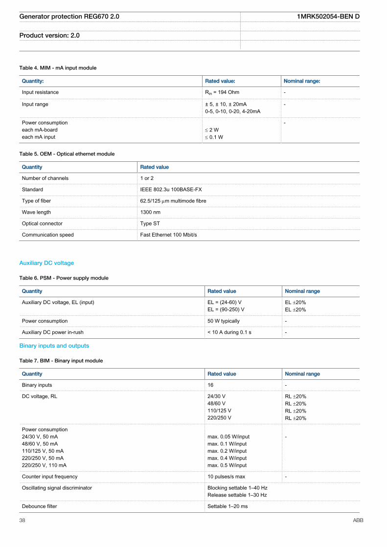
Table 4. MIM - mA input module
Quantity: Rated value: Nominal range:
Input resistance Rin = 194 Ohm -
Input range ± 5, ± 10, ± 20mA0-5, 0-10, 0-20, 4-20mA
-
Power consumptioneach mA-boardeach mA input
£ 2 W£ 0.1 W
-
Table 5. OEM - Optical ethernet module
Quantity Rated value
Number of channels 1 or 2
Standard IEEE 802.3u 100BASE-FX
Type of fiber 62.5/125 mm multimode fibre
Wave length 1300 nm
Optical connector Type ST
Communication speed Fast Ethernet 100 Mbit/s
Auxiliary DC voltage
Table 6. PSM - Power supply module
Quantity Rated value Nominal range
Auxiliary DC voltage, EL (input) EL = (24-60) VEL = (90-250) V
EL ±20%EL ±20%
Power consumption 50 W typically -
Auxiliary DC power in-rush < 10 A during 0.1 s -
Binary inputs and outputs
Table 7. BIM - Binary input module
Quantity Rated value Nominal range
Binary inputs 16 -
DC voltage, RL 24/30 V48/60 V110/125 V220/250 V
RL ±20%RL ±20%RL ±20%RL ±20%
Power consumption24/30 V, 50 mA48/60 V, 50 mA110/125 V, 50 mA220/250 V, 50 mA220/250 V, 110 mA
max. 0.05 W/inputmax. 0.1 W/inputmax. 0.2 W/inputmax. 0.4 W/inputmax. 0.5 W/input
-
Counter input frequency 10 pulses/s max -
Oscillating signal discriminator Blocking settable 1–40 HzRelease settable 1–30 Hz
Debounce filter Settable 1–20 ms
Generator protection REG670 2.0 1MRK502054-BEN D
Product version: 2.0
38 ABB

Maximum 176 binary input channels may beactivated simultaneously with influencingfactors within nominal range.
Table 8. BIM - Binary input module with enhanced pulse counting capabilities
Quantity Rated value Nominal range
Binary inputs 16 -
DC voltage, RL 24/30 V48/60 V110/125 V220/250 V
RL ±20%RL ±20%RL ±20%RL ±20%
Power consumption24/30 V48/60 V110/125 V220/250 V
max. 0.05 W/inputmax. 0.1 W/inputmax. 0.2 W/inputmax. 0.4 W/input
-
Counter input frequency 10 pulses/s max -
Balanced counter input frequency 40 pulses/s max -
Oscillating signal discriminator Blocking settable 1–40 HzRelease settable 1–30 Hz
Debounce filter Settable 1-20 ms
Maximum 176 binary input channels may beactivated simultaneously with influencingfactors within nominal range.
Table 9. IOM - Binary input/output module
Quantity Rated value Nominal range
Binary inputs 8 -
DC voltage, RL 24/30 V48/60 V110/125 V220/250 V
RL ±20%RL ±20%RL ±20%RL ±20%
Power consumption24/30 V, 50 mA48/60 V, 50 mA110/125 V, 50 mA220/250 V, 50 mA220/250 V, 110 mA
max. 0.05 W/inputmax. 0.1 W/inputmax. 0.2 W/inputmax. 0.4 W/inputmax. 0.5 W/input
-
Counter input frequency 10 pulses/s max
Oscillating signal discriminator Blocking settable 1-40 HzRelease settable 1-30 Hz
Debounce filter Settable 1-20 ms
Maximum 176 binary input channels may beactivated simultaneously with influencingfactors within nominal range.
Generator protection REG670 2.0 1MRK502054-BEN D
Product version: 2.0
ABB 39
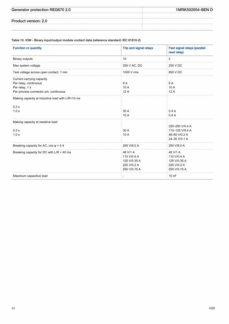
Table 10. IOM - Binary input/output module contact data (reference standard: IEC 61810-2)
Function or quantity Trip and signal relays Fast signal relays (parallelreed relay)
Binary outputs 10 2
Max system voltage 250 V AC, DC 250 V DC
Test voltage across open contact, 1 min 1000 V rms 800 V DC
Current carrying capacityPer relay, continuousPer relay, 1 sPer process connector pin, continuous
8 A10 A12 A
8 A10 A12 A
Making capacity at inductive load with L/R>10 ms 0.2 s1.0 s
30 A10 A
0.4 A0.4 A
Making capacity at resistive load 0.2 s1.0 s
30 A10 A
220–250 V/0.4 A110–125 V/0.4 A48–60 V/0.2 A24–30 V/0.1 A
Breaking capacity for AC, cos φ > 0.4 250 V/8.0 A 250 V/8.0 A
Breaking capacity for DC with L/R < 40 ms 48 V/1 A110 V/0.4 A125 V/0.35 A220 V/0.2 A250 V/0.15 A
48 V/1 A110 V/0.4 A125 V/0.35 A220 V/0.2 A250 V/0.15 A
Maximum capacitive load - 10 nF
Generator protection REG670 2.0 1MRK502054-BEN D
Product version: 2.0
40 ABB

Table 11. IOM with MOV and IOM 220/250 V, 110mA - contact data (reference standard: IEC 61810-2)
Function or quantity Trip and Signal relays Fast signal relays (parallel reed relay)
Binary outputs IOM: 10 IOM: 2
Max system voltage 250 V AC, DC 250 V DC
Test voltage across open contact,1 min
250 V rms 250 V rms
Current carrying capacityPer relay, continuousPer relay, 1 sPer process connector pin,continuous
8 A10 A12 A
8 A10 A12 A
Making capacity at inductiveloadwith L/R>10 ms0.2 s1.0 s
30 A10 A
0.4 A0.4 A
Making capacity at resistive load 0.2 s1.0 s
30 A10 A
220–250 V/0.4 A110–125 V/0.4 A48–60 V/0.2 A24–30 V/0.1 A
Breaking capacity for AC, cosj>0.4
250 V/8.0 A 250 V/8.0 A
Breaking capacity for DC with L/R< 40 ms
48 V/1 A110 V/0.4 A220 V/0.2 A250 V/0.15 A
48 V/1 A110 V/0.4 A220 V/0.2 A250 V/0.15 A
Maximum capacitive load - 10 nF
Table 12. SOM - Static Output Module (reference standard: IEC 61810-2): Static binary outputs
Function of quantity Static binary output trip
Rated voltage 48-60 VDC 110-250 VDC
Number of outputs 6 6
Impedance open state ~300 kΩ ~810 kΩ
Test voltage across open contact, 1 min No galvanic separation No galvanic separation
Current carrying capacity:
Continuous 5 A 5 A
1.0 s 10 A 10 A
Making capacity at capacitive load with themaximum capacitance of 0.2 μF :
0.2 s 30 A 30 A
1.0 s 10 A 10 A
Breaking capacity for DC with L/R ≤ 40 ms 48 V/1 A 110 V/0.4 A
60 V/0.75 A 125 V/0.35 A
220 V/0.2 A
250 V/0.15 A
Operating time < 1 ms < 1 ms
Generator protection REG670 2.0 1MRK502054-BEN D
Product version: 2.0
ABB 41
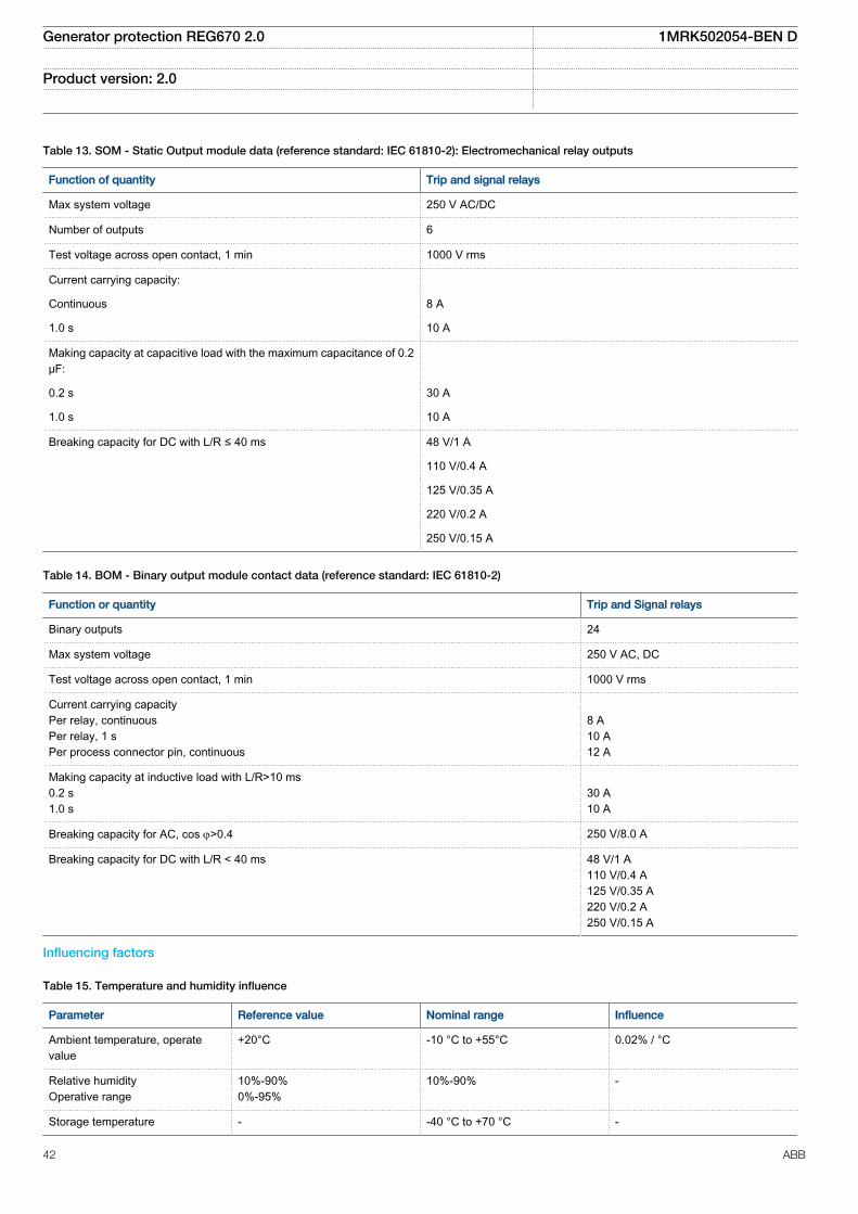
Table 13. SOM - Static Output module data (reference standard: IEC 61810-2): Electromechanical relay outputs
Function of quantity Trip and signal relays
Max system voltage 250 V AC/DC
Number of outputs 6
Test voltage across open contact, 1 min 1000 V rms
Current carrying capacity:
Continuous 8 A
1.0 s 10 A
Making capacity at capacitive load with the maximum capacitance of 0.2μF:
0.2 s 30 A
1.0 s 10 A
Breaking capacity for DC with L/R ≤ 40 ms 48 V/1 A
110 V/0.4 A
125 V/0.35 A
220 V/0.2 A
250 V/0.15 A
Table 14. BOM - Binary output module contact data (reference standard: IEC 61810-2)
Function or quantity Trip and Signal relays
Binary outputs 24
Max system voltage 250 V AC, DC
Test voltage across open contact, 1 min 1000 V rms
Current carrying capacityPer relay, continuousPer relay, 1 sPer process connector pin, continuous
8 A10 A12 A
Making capacity at inductive load with L/R>10 ms0.2 s1.0 s
30 A10 A
Breaking capacity for AC, cos j>0.4 250 V/8.0 A
Breaking capacity for DC with L/R < 40 ms 48 V/1 A110 V/0.4 A125 V/0.35 A220 V/0.2 A250 V/0.15 A
Influencing factors
Table 15. Temperature and humidity influence
Parameter Reference value Nominal range Influence
Ambient temperature, operatevalue
+20°C -10 °C to +55°C 0.02% / °C
Relative humidityOperative range
10%-90%0%-95%
10%-90% -
Storage temperature - -40 °C to +70 °C -
Generator protection REG670 2.0 1MRK502054-BEN D
Product version: 2.0
42 ABB

Table 16. Auxiliary DC supply voltage influence on functionality during operation
Dependence on Reference value Within nominalrange
Influence
Ripple, in DC auxiliary voltageOperative range
max. 2%Full wave rectified
15% of EL 0.01% / %
Auxiliary voltage dependence, operatevalue
±20% of EL 0.01% / %
Interrupted auxiliary DC voltage
24-60 V DC ± 20% 90-250 V DC ±20%
Interruption interval0–50 ms
No restart
0–∞ s Correct behaviour at power down
Restart time <300 s
Table 17. Frequency influence (reference standard: IEC 60255–1)
Dependence on Within nominal range Influence
Frequency dependence, operate value fr ±2.5 Hz for 50 Hzfr ±3.0 Hz for 60 Hz
±1.0% / Hz
Frequency dependence for distance protection operate value fr ±2.5 Hz for 50 Hzfr ±3.0 Hz for 60 Hz
±2.0% / Hz
Harmonic frequency dependence (20% content) 2nd, 3rd and 5th harmonic of fr ±2.0%
Harmonic frequency dependence for high impedance differentialprotection (10% content)
2nd, 3rd and 5th harmonic of fr ±5.0%
Harmonic frequency dependence for high impedance differentialprotection (10% content)
2nd, 3rd and 5th harmonic of fr ±10.0%
Harmonic frequency dependence for overcurrent protection 2nd, 3rd and 5th harmonic of fr ±3.0% / Hz
Generator protection REG670 2.0 1MRK502054-BEN D
Product version: 2.0
ABB 43

Type tests according to standards
Table 18. Electromagnetic compatibility
Test Type test values Reference standards
1 MHz burst disturbance 2.5 kV IEC 60255-26
100 kHz slow damped oscillatory wave immunity test 2.5 kV IEC 61000-4-18, Class III
Ring wave immunity test, 100 kHz 2-4 kV IEC 61000-4-12, Class IV
Surge withstand capability test 2.5 kV, oscillatory4.0 kV, fast transient
IEEE/ANSI C37.90.1
Electrostatic dischargeDirect applicationIndirect application
15 kV air discharge8 kV contact discharge8 kV contact discharge
IEC 60255-26 IEC 61000-4-2, Class IV
Electrostatic dischargeDirect applicationIndirect application
15 kV air discharge8 kV contact discharge8 kV contact discharge
IEEE/ANSI C37.90.1
Fast transient disturbance 4 kV IEC 60255-26, Zone A
Surge immunity test 2-4 kV, 1.2/50 mshigh energy
IEC 60255-26, Zone A
Power frequency immunity test 150-300 V, 50 Hz IEC 60255-26, Zone A
Conducted common mode immunity test 15 Hz-150 kHz IEC 61000-4-16, Class IV
Power frequency magnetic field test 1000 A/m, 3 s100 A/m, cont.
IEC 61000-4-8, Class V
Pulse magnetic field immunity test 1000 A/m IEC 61000–4–9, Class V
Damped oscillatory magnetic field test 100 A/m IEC 61000-4-10, Class V
Radiated electromagnetic field disturbance 20 V/m, 80-1000 MHz 1.4-2.7 GHz
IEC 60255-26
Radiated electromagnetic field disturbance 20 V/m80-1000 MHz
IEEE/ANSI C37.90.2
Conducted electromagnetic field disturbance 10 V, 0.15-80 MHz IEC 60255-26
Radiated emission 30-5000 MHz IEC 60255-26
Radiated emission 30-5000 MHz IEEE/ANSI C63.4, FCC
Conducted emission 0.15-30 MHz IEC 60255-26
Table 19. Insulation
Test Type test values Reference standard
Dielectric test 2.0 kV AC, 1 min. IEC 60255-27ANSI C37.90
Impulse voltage test 5 kV, 1.2/50 ms, 0.5 J
Insulation resistance >100 MW at 500 VDC
Generator protection REG670 2.0 1MRK502054-BEN D
Product version: 2.0
44 ABB

Table 20. Environmental tests
Test Type test value Reference standard
Cold operation test Test Ad for 16 h at -25°C IEC 60068-2-1
Cold storage test Test Ab for 16 h at -40°C IEC 60068-2-1
Dry heat operation test Test Bd for 16 h at +70°C IEC 60068-2-2
Dry heat storage test Test Bb for 16 h at +85°C IEC 60068-2-2
Change of temperature test Test Nb for 5 cycles at -25°C to +70°C IEC 60068-2-14
Damp heat test, steady state Test Ca for 10 days at +40°C and humidity 93% IEC 60068-2-78
Damp heat test, cyclic Test Db for 6 cycles at +25 to +55°C and humidity 93 to 95% (1 cycle = 24hours)
IEC 60068-2-30
Table 21. CE compliance
Test According to
Immunity EN 60255–26
Emissivity EN 60255–26
Low voltage directive EN 60255–27
Table 22. Mechanical tests
Test Type test values Reference standards
Vibration response test Class II IEC 60255-21-1
Vibration endurance test Class I IEC 60255-21-1
Shock response test Class I IEC 60255-21-2
Shock withstand test Class I IEC 60255-21-2
Bump test Class I IEC 60255-21-2
Seismic test Class II IEC 60255-21-3
Generator protection REG670 2.0 1MRK502054-BEN D
Product version: 2.0
ABB 45

Injection equipment
Table 23. Electromagnetic compatibility tests
Test Type test values Reference standards
1 MHz burst disturbance 2.5 kV IEC 60255-26
100 kHz slow damped oscillatory wave immunity test 2.5 kV IEC 61000-4-18, Class III
Surge withstand capability test 2.5 kV, oscillatory4.0 kV, fast transient
IEEE/ANSI C37.90.1
Electrostatic dischargeDirect applicationIndirect application
15 kV air discharge8 kV contact discharge8 kV contact discharge
IEC 60255-26 IEC 61000-4-2, Class IV
Electrostatic dischargeDirect applicationIndirect application
15 kV air discharge8 kV contact discharge8 kV contact discharge
IEEE/ANSI C37.90.3
Fast transient disturbance test 4 kV IEC 60255-26, Zone A
Surge immunity test 1-2 kV, and 2-4 kV, 1.2/50 µsHigh energy
IEC 60255-26, Zone A
Power frequency immunity test 150-300 V, 50 Hz IEC 60255-26, Zone A
Power frequency magnetic field test 1000 A/m, 3 s100 A/m, cont.
IEC 61000-4-8
Radiated electromagnetic field disturbance test 20 V/m, 80-1000 MHz1.4-2.7 GHz
IEC 60255-26
Radiated electromagnetic field disturbance test 20 V/m, 80-1000 MHz IEEE/ANSI C37.90.2
Conducted electromagnetic field disturbance test 10 V, 0.15-80 MHz IEC 60255-26
Voltage dips and short interruptions Dips:40% /200 ms70% /500 msInterruptions:0-50 ms: No restart0… ∞ s: Correct behaviour atpower down
IEC 60255-26
Radiated emission 30-1000 MHz IEC 60255-26
Conducted emission 0.15-30 MHz IEC 60255-26
Table 24. Insulation tests, REX060, REX062 and REG670
Test Type test values Reference standard
Dielectric test 2.0 kV AC, 1 min IEC 60255-27
Impulse voltage test 5.0 kV, 1.2/50 µs, 0.5 J IEC 60255-27
Insulation resistance >100 MΩ at 500V DC IEC 60255-27
Generator protection REG670 2.0 1MRK502054-BEN D
Product version: 2.0
46 ABB
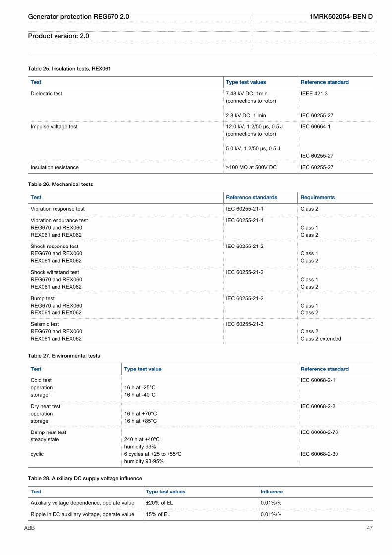
Table 25. Insulation tests, REX061
Test Type test values Reference standard
Dielectric test 7.48 kV DC, 1min(connections to rotor) 2.8 kV DC, 1 min
IEEE 421.3 IEC 60255-27
Impulse voltage test 12.0 kV, 1.2/50 µs, 0.5 J(connections to rotor) 5.0 kV, 1.2/50 µs, 0.5 J
IEC 60664-1 IEC 60255-27
Insulation resistance >100 MΩ at 500V DC IEC 60255-27
Table 26. Mechanical tests
Test Reference standards Requirements
Vibration response test IEC 60255-21-1 Class 2
Vibration endurance testREG670 and REX060REX061 and REX062
IEC 60255-21-1 Class 1Class 2
Shock response testREG670 and REX060REX061 and REX062
IEC 60255-21-2 Class 1Class 2
Shock withstand testREG670 and REX060REX061 and REX062
IEC 60255-21-2 Class 1Class 2
Bump testREG670 and REX060REX061 and REX062
IEC 60255-21-2 Class 1Class 2
Seismic testREG670 and REX060REX061 and REX062
IEC 60255-21-3 Class 2Class 2 extended
Table 27. Environmental tests
Test Type test value Reference standard
Cold testoperationstorage
16 h at -25°C16 h at -40°C
IEC 60068-2-1
Dry heat testoperationstorage
16 h at +70°C16 h at +85°C
IEC 60068-2-2
Damp heat teststeady state cyclic
240 h at +40ºChumidity 93%6 cycles at +25 to +55ºChumidity 93-95%
IEC 60068-2-78 IEC 60068-2-30
Table 28. Auxiliary DC supply voltage influence
Test Type test values Influence
Auxiliary voltage dependence, operate value ±20% of EL 0.01%/%
Ripple in DC auxiliary voltage, operate value 15% of EL 0.01%/%
Generator protection REG670 2.0 1MRK502054-BEN D
Product version: 2.0
ABB 47

Table 29. Temperature influence
Test Type test values Influence
Ambient temperature, operate value -25°C to +55°C 0.02%/°C
Storage temperature -40°C to +85°C -
Table 30. Degree of protection
Description Values
REX060FrontPanel mounted, frontRear, sides, top, bottom and connection terminals
IP40IP54IP20
REX061 and REX062TopFront, rear, sides and bottom
IP41IP20
Generator protection REG670 2.0 1MRK502054-BEN D
Product version: 2.0
48 ABB
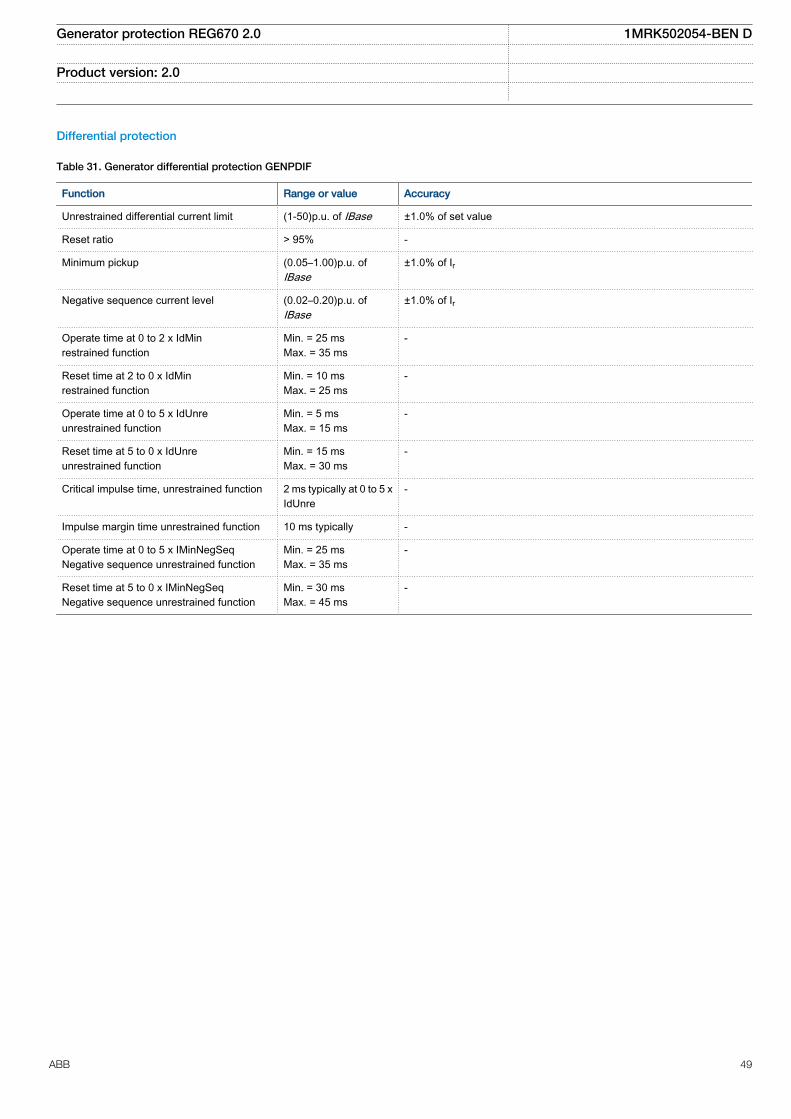
Differential protection
Table 31. Generator differential protection GENPDIF
Function Range or value Accuracy
Unrestrained differential current limit (1-50)p.u. of IBase ±1.0% of set value
Reset ratio > 95% -
Minimum pickup (0.05–1.00)p.u. ofIBase
±1.0% of Ir
Negative sequence current level (0.02–0.20)p.u. ofIBase
±1.0% of Ir
Operate time at 0 to 2 x IdMinrestrained function
Min. = 25 msMax. = 35 ms
-
Reset time at 2 to 0 x IdMinrestrained function
Min. = 10 msMax. = 25 ms
-
Operate time at 0 to 5 x IdUnreunrestrained function
Min. = 5 msMax. = 15 ms
-
Reset time at 5 to 0 x IdUnreunrestrained function
Min. = 15 msMax. = 30 ms
-
Critical impulse time, unrestrained function 2 ms typically at 0 to 5 xIdUnre
-
Impulse margin time unrestrained function 10 ms typically -
Operate time at 0 to 5 x IMinNegSeqNegative sequence unrestrained function
Min. = 25 msMax. = 35 ms
-
Reset time at 5 to 0 x IMinNegSeqNegative sequence unrestrained function
Min. = 30 msMax. = 45 ms
-
Generator protection REG670 2.0 1MRK502054-BEN D
Product version: 2.0
ABB 49

Table 32. Transformer differential protection T2WPDIF, T3WPDIF
Function Range or value Accuracy
Operating characteristic Adaptable ±1.0% of Ir at I ≤ Ir±1.0% of I at I > Ir
Reset ratio > 90% -
Unrestrained differential current limit (100-5000)% ofIBase on high voltagewinding
±1.0% of set value
Minimum pickup (5-60)% of IBase ±1.0% of Ir
Second harmonic blocking (5.0-100.0)% of fundamentaldifferential current
±1.0% of IrNote: fundamental magnitude = 100% of Ir
Fifth harmonic blocking (5.0-100.0)% of fundamentaldifferential current
±5.0% of IrNote: fundamental magnitude = 100% of Ir
Connection type for each of the windings Y or D -
Phase displacement between highvoltage winding, W1 and each of thewindings, W2 and W3. Hour notation
0–11 -
*Operate time at 0 to 10 x IdMin,restrained function
Min. = 25 msMax. = 35 ms
-
*Reset time at 10 to 0 x IdMin, restrainedfunction
Min. = 5 msMax. = 15 ms
-
*Operate time at 0 to 10 x Idunre,unrestrained function
Min. = 5 msMax. = 15 ms
-
*Reset time at 10 to 0 x Idunre,unrestrained function
Min. = 15 msMax. = 30 ms
-
**Operate time, unrestrained negativesequence function
Min. = 10 msMax. = 20 ms
-
**Reset time, unrestrained negativesequence function
Min. = 10 msMax. = 30 ms
-
Critical impulse time 2 ms typically at 0 to 5 x IdMin -
*Note: Data obtained with single input current group.**Note: Data obtained with two input current groups. The rated symmetrical currents are applied on both sides as pre- and after-fault currents. Thefault is performed by increasing one phase current to double on one side and decreasing same phase current to zero on the other side.
Generator protection REG670 2.0 1MRK502054-BEN D
Product version: 2.0
50 ABB

Table 33. Restricted earth-fault protection, low impedance REFPDIF
Function Range or value Accuracy
Operate characteristic Adaptable ± 1.0% of Ir for I ≤ Ir± 1.0% of I for I > Ir
Reset ratio >95% -
Minimum pickup (4.0-100.0)% of IBase ± 1.0% of Ir
Directional characteristic Fixed 180 degrees or ± 60 to ± 90degrees
± 2.0 degrees
Operate time, trip at 0 to 10 xIdMin
Min = 15 msMax = 30 ms
-
Reset time, trip at 10 to 0 x IdMin Min = 15 msMax = 30 ms
-
Second harmonic blocking 60.0% of fundamental (hiddensetting)
± 1.0% of Ir
Table 34. 1Ph High impedance differential protection HZPDIF
Function Range or value Accuracy
Operate voltage (10-900) VI=U/R
± 1.0% of Ir at I ≤ Ir± 1.0% of I at I > Ir
Reset ratio >95% at (30-900) V -
Maximum continuous power U>Trip2/SeriesResistor ≤200 W -
Operate time at 0 to 10 x Ud Min = 5 msMax = 15 ms
Reset time at 10 to 0 x Ud Min = 75 msMax = 95 ms
Critical impulse time 2 ms typically at 0 to 10 x Ud -
Operate time at 0 to 2 x Ud Min = 25 msMax = 35 ms
Reset time at 2 to 0 x Ud Min = 50 msMax = 70 ms
Critical impulse time 15 ms typically at 0 to 2 x Ud -
Generator protection REG670 2.0 1MRK502054-BEN D
Product version: 2.0
ABB 51
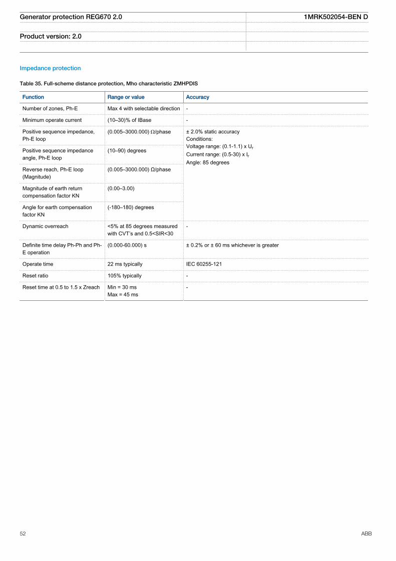
Impedance protection
Table 35. Full-scheme distance protection, Mho characteristic ZMHPDIS
Function Range or value Accuracy
Number of zones, Ph-E Max 4 with selectable direction -
Minimum operate current (10–30)% of IBase -
Positive sequence impedance,Ph-E loop
(0.005–3000.000) W/phase ± 2.0% static accuracyConditions:Voltage range: (0.1-1.1) x UrCurrent range: (0.5-30) x IrAngle: 85 degrees
Positive sequence impedanceangle, Ph-E loop
(10–90) degrees
Reverse reach, Ph-E loop(Magnitude)
(0.005–3000.000) Ω/phase
Magnitude of earth returncompensation factor KN
(0.00–3.00)
Angle for earth compensationfactor KN
(-180–180) degrees
Dynamic overreach <5% at 85 degrees measuredwith CVT’s and 0.5<SIR<30
-
Definite time delay Ph-Ph and Ph-E operation
(0.000-60.000) s ± 0.2% or ± 60 ms whichever is greater
Operate time 22 ms typically IEC 60255-121
Reset ratio 105% typically -
Reset time at 0.5 to 1.5 x Zreach Min = 30 msMax = 45 ms
-
Generator protection REG670 2.0 1MRK502054-BEN D
Product version: 2.0
52 ABB

Table 36. Fast distance protection ZMFPDIS, ZMFCPDIS
Function Range or value Accuracy
Number of zones 3 selectable directions,3 fixed directions
-
Minimum operate current, Ph-Phand Ph-E
(5-6000)% of IBase ±1.0% of Ir
Positive sequence reactancereach, Ph-E and Ph-Ph loop
(0.01 - 3000.00) ohm/phase
±2.0% of static accuracy±2.0 deg static angular accuracyConditions:Voltage range: (0.1-1.1) x UrCurrent range: (0.5-30) x IrAngle: At 0 deg and 85 deg
Positive sequence resistancereach, Ph-E and Ph-Ph loop
(0.00 - 1000.00) ohm/phase
Zero sequence reactance reach (0.01 - 9000.00) ohm/p
Zero sequence resistive reach (0.00 - 3000.00) ohm/p
Fault resistance reach, Ph-E andPh-Ph
(0.01 -9000.00) ohm/l
Dynamic overreach < 5% at 85 degmeasured with CVTsand 0.5 < SIR < 30
Definite time delay to trip, Ph-Eand Ph-Ph operation
(0.000-60.000) s ±2.0% or ±35 ms whichever is greater
Operate time 16 ms typically IEC 60255-121
Reset time at 0.1 to 2 x Zreach Min = 20 msMax = 35 ms
-
Reset ratio 105% typically -
Table 37. Pole slip protection PSPPPAM
Function Range or value Accuracy
Impedance reach (0.00 - 1000.00)% of Zbase ±2.0% of Ur/Ir
Zone 1 and Zone 2 trip counters (1 - 20) -
Table 38. Out-of-step protection OOSPPAM
Function Range or value Accuracy
Impedance reach (0.00 - 1000.00)% of Zbase ±2.0% of Ur/(√3 ⋅ Ir)
Rotor start angle (90.0 - 130.0) degrees ±5.0 degrees
Rotor trip angle (15.0 - 90.0) degrees ±5.0 degrees
Zone 1 and Zone 2 trip counters (1 - 20) -
Generator protection REG670 2.0 1MRK502054-BEN D
Product version: 2.0
ABB 53
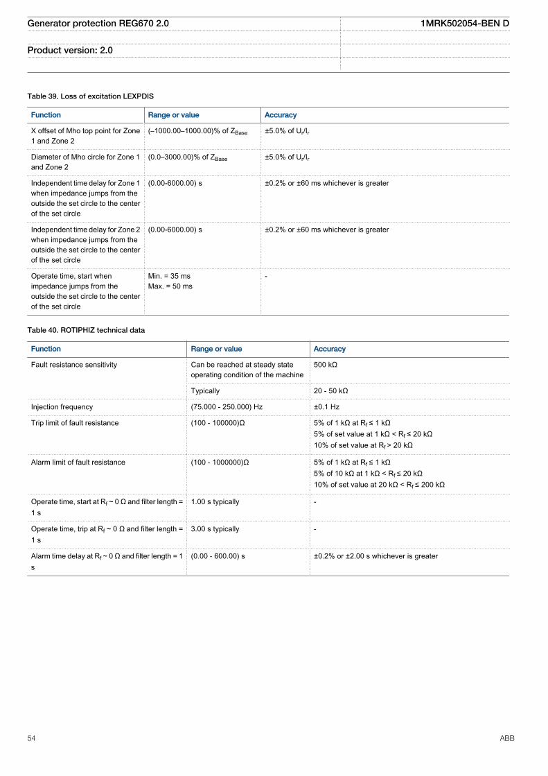
Table 39. Loss of excitation LEXPDIS
Function Range or value Accuracy
X offset of Mho top point for Zone1 and Zone 2
(–1000.00–1000.00)% of ZBase ±5.0% of Ur/Ir
Diameter of Mho circle for Zone 1and Zone 2
(0.0–3000.00)% of ZBase ±5.0% of Ur/Ir
Independent time delay for Zone 1when impedance jumps from theoutside the set circle to the centerof the set circle
(0.00-6000.00) s ±0.2% or ±60 ms whichever is greater
Independent time delay for Zone 2when impedance jumps from theoutside the set circle to the centerof the set circle
(0.00-6000.00) s ±0.2% or ±60 ms whichever is greater
Operate time, start whenimpedance jumps from theoutside the set circle to the centerof the set circle
Min. = 35 msMax. = 50 ms
-
Table 40. ROTIPHIZ technical data
Function Range or value Accuracy
Fault resistance sensitivity Can be reached at steady stateoperating condition of the machine
500 kΩ
Typically 20 - 50 kΩ
Injection frequency (75.000 - 250.000) Hz ±0.1 Hz
Trip limit of fault resistance (100 - 100000)Ω 5% of 1 kΩ at Rf ≤ 1 kΩ5% of set value at 1 kΩ < Rf ≤ 20 kΩ10% of set value at Rf > 20 kΩ
Alarm limit of fault resistance (100 - 1000000)Ω 5% of 1 kΩ at Rf ≤ 1 kΩ5% of 10 kΩ at 1 kΩ < Rf ≤ 20 kΩ10% of set value at 20 kΩ < Rf ≤ 200 kΩ
Operate time, start at Rf ~ 0 Ω and filter length =1 s
1.00 s typically -
Operate time, trip at Rf ~ 0 Ω and filter length =1 s
3.00 s typically -
Alarm time delay at Rf ~ 0 Ω and filter length = 1s
(0.00 - 600.00) s ±0.2% or ±2.00 s whichever is greater
Generator protection REG670 2.0 1MRK502054-BEN D
Product version: 2.0
54 ABB
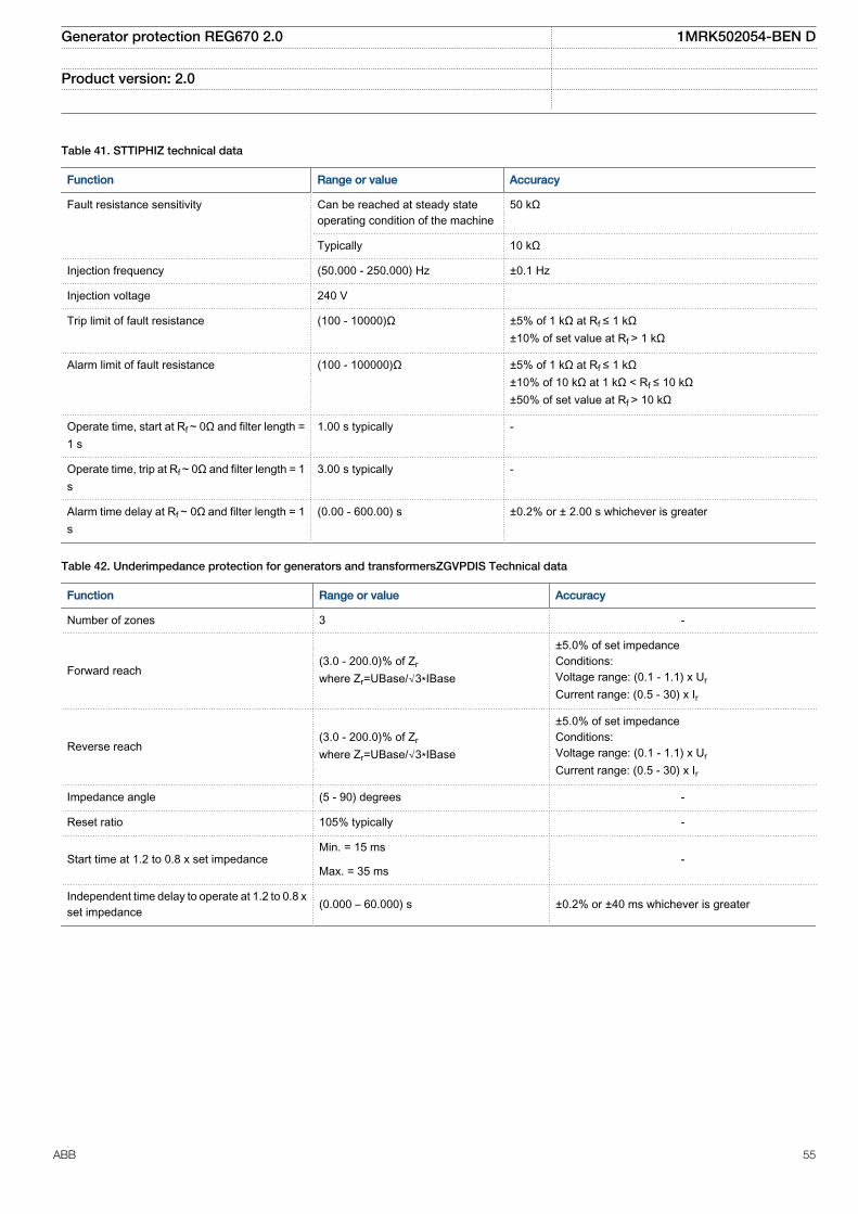
Table 41. STTIPHIZ technical data
Function Range or value Accuracy
Fault resistance sensitivity Can be reached at steady stateoperating condition of the machine
50 kΩ
Typically 10 kΩ
Injection frequency (50.000 - 250.000) Hz ±0.1 Hz
Injection voltage 240 V
Trip limit of fault resistance (100 - 10000)Ω ±5% of 1 kΩ at Rf ≤ 1 kΩ±10% of set value at Rf > 1 kΩ
Alarm limit of fault resistance (100 - 100000)Ω ±5% of 1 kΩ at Rf ≤ 1 kΩ±10% of 10 kΩ at 1 kΩ < Rf ≤ 10 kΩ±50% of set value at Rf > 10 kΩ
Operate time, start at Rf ~ 0Ω and filter length =1 s
1.00 s typically -
Operate time, trip at Rf ~ 0Ω and filter length = 1s
3.00 s typically -
Alarm time delay at Rf ~ 0Ω and filter length = 1s
(0.00 - 600.00) s ±0.2% or ± 2.00 s whichever is greater
Table 42. Underimpedance protection for generators and transformersZGVPDIS Technical data
Function Range or value Accuracy
Number of zones 3 -
Forward reach(3.0 - 200.0)% of Zrwhere Zr=UBase/√3∗IBase
±5.0% of set impedanceConditions:Voltage range: (0.1 - 1.1) x UrCurrent range: (0.5 - 30) x Ir
Reverse reach(3.0 - 200.0)% of Zrwhere Zr=UBase/√3∗IBase
±5.0% of set impedanceConditions:Voltage range: (0.1 - 1.1) x UrCurrent range: (0.5 - 30) x Ir
Impedance angle (5 - 90) degrees -
Reset ratio 105% typically -
Start time at 1.2 to 0.8 x set impedanceMin. = 15 ms
-Max. = 35 ms
Independent time delay to operate at 1.2 to 0.8 xset impedance (0.000 – 60.000) s ±0.2% or ±40 ms whichever is greater
Generator protection REG670 2.0 1MRK502054-BEN D
Product version: 2.0
ABB 55

Current protection
Table 43. Instantaneous phase overcurrent protection PHPIOC
Function Range or value Accuracy
Operate current (5-2500)% of lBase ± 1.0% of Ir at I ≤ Ir± 1.0% of I at I > Ir
Reset ratio > 95% at (50–2500)% of IBase -
Operate time at 0 to 2 x Iset Min. = 15 msMax. = 25 ms
-
Reset time at 2 to 0 x Iset Min. = 15msMax. = 25ms
-
Critical impulse time 10 ms typically at 0 to 2 x Iset -
Operate time at 0 to 10 x Iset Min. = 5msMax. = 15 ms
-
Reset time at 10 to 0 x Iset Min. = 25msMax. = 40 ms
-
Critical impulse time 2 ms typically at 0 to 10 x Iset -
Dynamic overreach < 5% at t = 100 ms -
Table 44. Four step phase overcurrent protection OC4PTOC
Function Setting range Accuracy
Operate current (5-2500)% of lBase ± 1.0% of Ir at I ≤ Ir± 1.0% of I at I > Ir
Reset ratio > 95% at (50–2500)% of lBase -
Min. operating current (1-10000)% of lBase ± 1.0% of Ir at I ≤ Ir±1.0% of I at I > Ir
Relay characteristic angle (RCA) (40.0–65.0) degrees ± 2.0 degrees
Relay operating angle (ROA) (40.0–89.0) degrees ± 2.0 degrees
2nd harmonic blocking (5–100)% of fundamental ± 2.0% of Ir
Independent time delay at 0 to 2 xIset
(0.000-60.000) s ± 0.2 % or ± 35 ms whichever isgreater
Minimum operate time (0.000-60.000) s ± 2.0 % or ± 40 ms whichever isgreater
Inverse characteristics, seetable 122, table 123 and table 124
16 curve types See table 122, table 123 and table 124
Operate time, start non-directionalat 0 to 2 x Iset
Min. = 15 ms
Max. = 30 ms
Reset time, start non-directional at2 to 0 x Iset
Min. = 15 ms
Max. = 30 ms
Critical impulse time 10 ms typically at 0 to 2 x Iset -
Impulse margin time 15 ms typically -
Generator protection REG670 2.0 1MRK502054-BEN D
Product version: 2.0
56 ABB
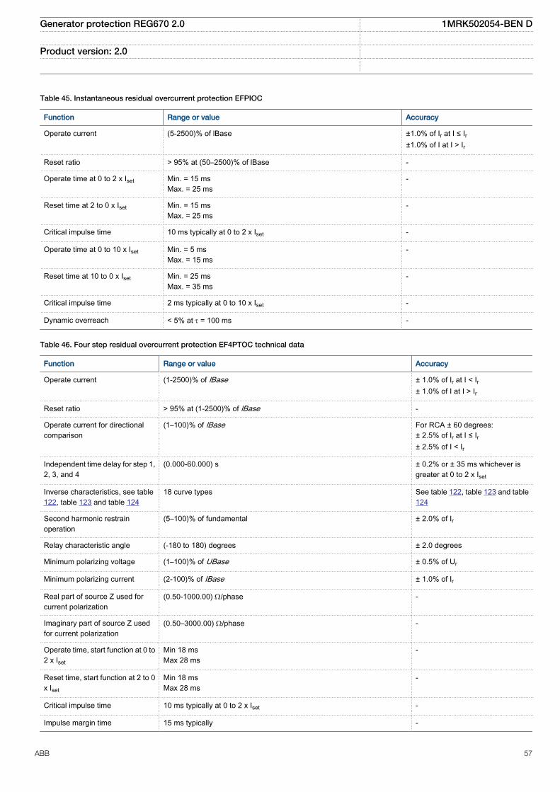
Table 45. Instantaneous residual overcurrent protection EFPIOC
Function Range or value Accuracy
Operate current (5-2500)% of lBase ±1.0% of Ir at I ≤ Ir±1.0% of I at I > Ir
Reset ratio > 95% at (50–2500)% of lBase -
Operate time at 0 to 2 x Iset Min. = 15 msMax. = 25 ms
-
Reset time at 2 to 0 x Iset Min. = 15 msMax. = 25 ms
-
Critical impulse time 10 ms typically at 0 to 2 x Iset -
Operate time at 0 to 10 x Iset Min. = 5 msMax. = 15 ms
-
Reset time at 10 to 0 x Iset Min. = 25 msMax. = 35 ms
-
Critical impulse time 2 ms typically at 0 to 10 x Iset -
Dynamic overreach < 5% at t = 100 ms -
Table 46. Four step residual overcurrent protection EF4PTOC technical data
Function Range or value Accuracy
Operate current (1-2500)% of lBase ± 1.0% of Ir at I < Ir± 1.0% of I at I > Ir
Reset ratio > 95% at (1-2500)% of lBase -
Operate current for directionalcomparison
(1–100)% of lBase For RCA ± 60 degrees:± 2.5% of Ir at I ≤ Ir± 2.5% of I < Ir
Independent time delay for step 1,2, 3, and 4
(0.000-60.000) s ± 0.2% or ± 35 ms whichever isgreater at 0 to 2 x Iset
Inverse characteristics, see table122, table 123 and table 124
18 curve types See table 122, table 123 and table124
Second harmonic restrainoperation
(5–100)% of fundamental ± 2.0% of Ir
Relay characteristic angle (-180 to 180) degrees ± 2.0 degrees
Minimum polarizing voltage (1–100)% of UBase ± 0.5% of Ur
Minimum polarizing current (2-100)% of IBase ± 1.0% of Ir
Real part of source Z used forcurrent polarization
(0.50-1000.00) W/phase -
Imaginary part of source Z usedfor current polarization
(0.50–3000.00) W/phase -
Operate time, start function at 0 to2 x Iset
Min 18 msMax 28 ms
-
Reset time, start function at 2 to 0x Iset
Min 18 msMax 28 ms
-
Critical impulse time 10 ms typically at 0 to 2 x Iset -
Impulse margin time 15 ms typically -
Generator protection REG670 2.0 1MRK502054-BEN D
Product version: 2.0
ABB 57

Table 47. Four step negative sequence overcurrent protection NS4PTOC
Function Range or value Accuracy
Operate value, negativesequence current, step 1-4
(1-2500)% of lBase ± 1.0% of Ir at I £ Ir± 1.0% of I at I > Ir
Reset ratio > 95% at (10-2500)% of IBase -
Independent time delay forstep 1, 2, 3, and 4 at 0 to 2 x Iset
(0.000-60.000) s ± 0.2% or ± 35 ms whichever isgreater
Inverse characteristics, seetable 122, table 123 and table124
16 curve types See table 122, table 123 and table124
Minimum operate current forsteps 1 - 4
(1.00 - 10000.00)% of IBase ± 1.0% of Ir at I ≤ Ir± 1.0% of I at I > Ir
Relay characteristic angle (-180 to 180) degrees ± 2.0 degrees
Operate value, negativecurrent for directional release
(1–100)% of IBase For RCA ± 60 degrees:± 2.5% of Ir at I ≤ Ir± 2.5% of I at I > Ir
Minimum polarizing voltage (1–100)% of UBase ± 0.5% of Ur
Minimum polarizing current (2-100)% of IBase ±1.0% of Ir
Real part of negative sequencesource impedance used forcurrent polarization
(0.50-1000.00) W/phase -
Imaginary part of negativesequence source impedanceused for current polarization
(0.50–3000.00) W/phase -
Operate time, start function at0 to 2 x Iset
Min = 15 msMax = 30 ms
-
Reset time, start function at 2to 0 x Iset
Min = 15 msMax = 30 ms
-
Critical impulse time, startfunction
10 ms typically at 0 to 2 x Iset -
Impulse margin time, startfunction
15 ms typically -
Transient overreach <10% at τ = 100 ms -
Generator protection REG670 2.0 1MRK502054-BEN D
Product version: 2.0
58 ABB

Table 48. Sensitive directional residual overcurrent and power protection SDEPSDE
Function Range or value Accuracy
Operate level for 3I0·cosjdirectional residualovercurrent
(0.25-200.00)% of lBase ± 1.0% of Ir at I £ Ir± 1.0% of I at I > Ir
Operate level for ·3I0·3U0 cosjdirectional residual power
(0.25-200.00)% of SBase ± 1.0% of Sr at S £ Sr± 1.0% of S at S > Sr
Operate level for 3I0 and jresidual overcurrent
(0.25-200.00)% of lBase ± 1.0% of Ir at £ Ir± 1.0% of I at I > Ir
Operate level for non-directional overcurrent
(1.00-400.00)% of lBase ±1.0% of Ir at I £ Ir± 1.0% of I at I > Ir
Operate level for non-directional residualovervoltage
(1.00-200.00)% of UBase ± 0.5% of Ur at U £ Ur± 0.5% of U at U > Ur
Residual release current for alldirectional modes
(0.25-200.00)% of lBase ± 1.0% of Ir at I £ Ir± 1.0% of I at I > Ir
Residual release voltage for alldirectional modes
(1.00-300.00)% of UBase ± 0.5% of Ur at U £ Ur± 0.5% of U at U > Ur
Operate time for non-directional residualovercurrent at 0 to 2 x Iset
Min = 40 ms
Max = 65 ms
Reset time for non-directionalresidual overcurrent at 2 to 0 xIset
Min = 40 ms
Max = 65 ms
Operate time for directionalresidual overcurrent at 0 to 2 xIset
Min = 115 ms
Max = 165 ms
Reset time for directionalresidual overcurrent at 2 to 0 xIset
Min = 25 ms
Max = 65 ms
Independent time delay fornon-directional residualovervoltage at 0.8 to 1.2 x Uset
(0.000 – 60.000) sec ±0.2% or ± 80 ms whichever is greater
Independent time delay fornon-directional residualovercurrent at 0 to 2 x Iset
(0.000 – 60.000) sec ±0.2% or ± 80 ms whichever is greater
Independent time delay fordirectional residualovercurrent at 0 to 2 x Iset
(0.000 – 60.000) sec ±0.2% or ± 180 ms whichever isgreater
Inverse characteristics 16 curve types See table 122, table 123 and table 124
Relay characteristic angleRCA
(-179 to 180) degrees ± 2.0 degrees
Relay Open angle ROA (0 to 90) degrees ± 2.0 degrees
Generator protection REG670 2.0 1MRK502054-BEN D
Product version: 2.0
ABB 59

Table 49. Thermal overload protection, two time constants TRPTTR
Function Range or value Accuracy
Base current 1 and 2 (30–250)% of IBase ±1.0% of Ir
Operate time:
2 2
2 2p
ref
I It ln
I It
æ ö-ç ÷= ×ç ÷-è ø
EQUATION1356 V2 EN (Equation 1)
I = actual measured currentIp = load current before overloadoccursIref = reference load current
Ip = load current before overloadoccursTime constant τ = (0.10–500.00)minutes
±5.0% or ±200 ms whichever is greater
Alarm level 1 and 2 (50–99)% of heat content operatevalue
±2.0% of heat content trip
Operate current (50–250)% of IBase ±1.0% of Ir
Reset level temperature (10–95)% of heat content trip ±2.0% of heat content trip
Table 50. Breaker failure protection CCRBRF
Function Range or value Accuracy
Operate phase current (5-200)% of lBase ±1.0% of Ir at I £ Ir±1.0% of I at I > Ir
Reset ratio, phase current > 95% -
Operate residual current (2-200)% of lBase ±1.0% of Ir at I £ Ir±1.0% of I at I > Ir
Reset ratio, residual current > 95% -
Phase current level for blocking of contact function (5-200)% of lBase ±1.0% of Ir at I £ Ir±1.0% of I at I > Ir
Reset ratio > 95% -
Operate time for current detection 10 ms typically -
Reset time for current detection 15 ms maximum -
Time delay for re-trip at 0 to 2 x Iset (0.000-60.000) s ±0.2% or ±15 ms whichever isgreater
Time delay for back-up trip at 0 to 2 x Iset (0.000-60.000) s ±0.2% or ±15 ms whichever isgreater
Time delay for back-up trip at multi-phase start at 0 to 2 x Iset (0.000-60.000) s ±0.2% or ±20 ms whichever isgreater
Additional time delay for a second back-up trip at 0 to 2 x Iset (0.000-60.000) s ±0.2% or ±20 ms whichever isgreater
Time delay for alarm for faulty circuit breaker (0.000-60.000) s ±0.2% or ±15 ms whichever isgreater
Generator protection REG670 2.0 1MRK502054-BEN D
Product version: 2.0
60 ABB

Table 51. Pole discordance protection CCPDSC
Function Range or value Accuracy
Operate current (0–100)% of IBase ±1.0% of Ir
Independent time delay betweentrip condition and trip signal
(0.000-60.000) s ±0.2% or ± 25 ms whichever is greater
Table 52. Directional underpower protection GUPPDUP
Function Range or value Accuracy
Power levelfor Step 1 and Step 2
(0.0–500.0)% of SBase ± 1.0% of Sr at S ≤ Sr± 1.0% of S at S > Srwhere
1.732r r rS U I= × ×
Characteristic anglefor Step 1 and Step 2
(-180.0–180.0) degrees ± 2.0 degrees
Independent time delay to operate for Step 1and Step 2 at 2 to 0.5 x Sr and k=0.000
(0.01-6000.00) s ± 0.2% or ± 40 ms whichever is greater
Table 53. Directional overpower protection GOPPDOP
Function Range or value Accuracy
Power levelfor Step 1 and Step 2
(0.0–500.0)% of SBase When measuring transformer inputs are used,the following accuracy can be obtained for lowpickup settings which are typical for reversepower protection application:
±1.0% of Sr at S ≤ Sr±1.0% of S at S > SrStart value P=0.5% of SrPickup accuracy of ±0.20% of Sr*)Start value P=0.2% of SrPickup accuracy of ±0.15% of Sr*)
where 1.732r r rS U I= × ×
Characteristic anglefor Step 1 and Step 2
(-180.0–180.0) degrees ±2.0 degrees
Operate time, start at 0.5 to 2 x Sr and k=0.000 Min. =10 ms
Max. = 25 ms
Reset time, start at 2 to 0.5 x Sr and k=0.000 Min. = 35 ms
Max. = 55 ms
Independent time delay to operate for Step 1and Step 2 at 0.5 to 2 x Sr and k=0.000
(0.01-6000.00) s ±0.2% or ±40 ms whichever is greater
*) To achieve this accuracy for reverse power protection it is also recommended to apply settings k=0.990 and Mode=PosSeq. These settings will helpto minimize the overall measurement error ensuring the best accuracy for this application.
Generator protection REG670 2.0 1MRK502054-BEN D
Product version: 2.0
ABB 61
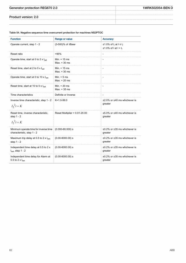
Table 54. Negative sequence time overcurrent protection for machines NS2PTOC
Function Range or value Accuracy
Operate current, step 1 - 2 (3-500)% of IBase ±1.0% of Ir at I ≤ Ir±1.0% of I at I > Ir
Reset ratio >95% -
Operate time, start at 0 to 2 x Iset Min. = 15 msMax. = 30 ms
-
Reset time, start at 2 to 0 x Iset Min. = 15 msMax. = 30 ms
-
Operate time, start at 0 to 10 x Iset Min. = 5 msMax. = 20 ms
-
Reset time, start at 10 to 0 x Iset Min. = 20 msMax. = 35 ms
-
Time characteristics Definite or Inverse -
Inverse time characteristic, step 1 - 2
22I t K=
K=1.0-99.0 ±2.0% or ±40 ms whichever isgreater
Reset time, inverse characteristic,step 1 - 2
22I t K=
Reset Multiplier = 0.01-20.00 ±5.0% or ±40 ms whichever isgreater
Minimum operate time for inverse timecharacteristic, step 1 - 2
(0.000-60.000) s ±0.2% or ±35 ms whichever isgreater
Maximum trip delay at 0.5 to 2 x Iset,step 1 - 2
(0.00-6000.00) s ±0.2% or ±35 ms whichever isgreater
Independent time delay at 0.5 to 2 xIset, step 1 - 2
(0.00-6000.00) s ±0.2% or ±35 ms whichever isgreater
Independent time delay for Alarm at0.5 to 2 x Iset
(0.00-6000.00) s ±0.2% or ±35 ms whichever isgreater
Generator protection REG670 2.0 1MRK502054-BEN D
Product version: 2.0
62 ABB
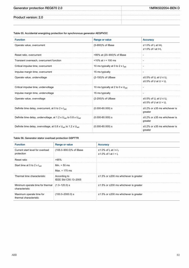
Table 55. Accidental energizing protection for synchronous generator AEGPVOC
Function Range or value Accuracy
Operate value, overcurrent (5-900)% of IBase ±1.0% of Ir at I≤Ir±1.0% of I at I>Ir
Reset ratio, overcurrent >95% at (20–900)% of IBase -
Transient overreach, overcurrent function <10% at τ = 100 ms -
Critical impulse time, overcurrent 10 ms typically at 0 to 2 x Iset -
Impulse margin time, overcurrent 15 ms typically -
Operate value, undervoltage (2-150)% of UBase ±0.5% of Ur at U ≤ Ur±0.5% of U at U > Ur
Critical impulse time, undervoltage 10 ms typically at 2 to 0 x Uset -
Impulse margin time, undervoltage 15 ms typically -
Operate value, overvoltage (2-200)% of UBase ±0.5% of Ur at U ≤ Ur±0.5% of U at U > Ur
Definite time delay, overcurrent, at 0 to 2 x Iset (0.000-60.000) s ±0.2% or ±35 ms whichever isgreater
Definite time delay, undervoltage, at 1.2 x Uset to 0.8 x Uset (0.000-60.000) s ±0.2% or ±35 ms whichever isgreater
Definite time delay, overvoltage, at 0.8 x Uset to 1.2 x Uset (0.000-60.000) s ±0.2% or ±35 ms whichever isgreater
Table 56. Generator stator overload protection GSPTTR
Function Range or value Accuracy
Current start level for overloadprotection
(105.0–900.0)% of IBase ±1.0% of Ir at I ≤ Ir±1.0% of I at I > Ir
Reset ratio >95%
Start time at 0 to 2 x Iset Min. = 50 ms
Max. = 170 ms
Thermal time characteristic According toIEEE Std C50.13–2005
±1.5% or ±200 ms whichever is greater
Minimum operate time for thermalcharacteristic
(1.0–120.0) s ±1.5% or ±200 ms whichever is greater
Maximum operate time forthermal characteristic
(100.0–2000.0) s ±1.5% or ±200 ms whichever is greater
Generator protection REG670 2.0 1MRK502054-BEN D
Product version: 2.0
ABB 63
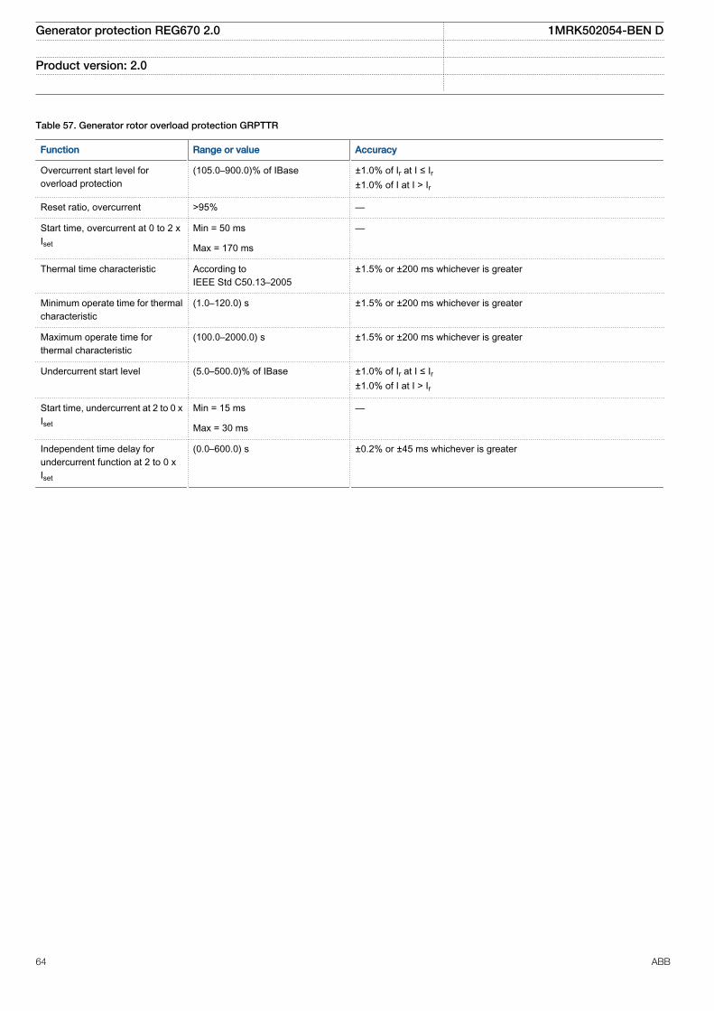
Table 57. Generator rotor overload protection GRPTTR
Function Range or value Accuracy
Overcurrent start level foroverload protection
(105.0–900.0)% of IBase ±1.0% of Ir at I ≤ Ir±1.0% of I at I > Ir
Reset ratio, overcurrent >95% —
Start time, overcurrent at 0 to 2 xIset
Min = 50 ms —
Max = 170 ms
Thermal time characteristic According toIEEE Std C50.13–2005
±1.5% or ±200 ms whichever is greater
Minimum operate time for thermalcharacteristic
(1.0–120.0) s ±1.5% or ±200 ms whichever is greater
Maximum operate time forthermal characteristic
(100.0–2000.0) s ±1.5% or ±200 ms whichever is greater
Undercurrent start level (5.0–500.0)% of IBase ±1.0% of Ir at I ≤ Ir±1.0% of I at I > Ir
Start time, undercurrent at 2 to 0 xIset
Min = 15 ms —
Max = 30 ms
Independent time delay forundercurrent function at 2 to 0 xIset
(0.0–600.0) s ±0.2% or ±45 ms whichever is greater
Generator protection REG670 2.0 1MRK502054-BEN D
Product version: 2.0
64 ABB
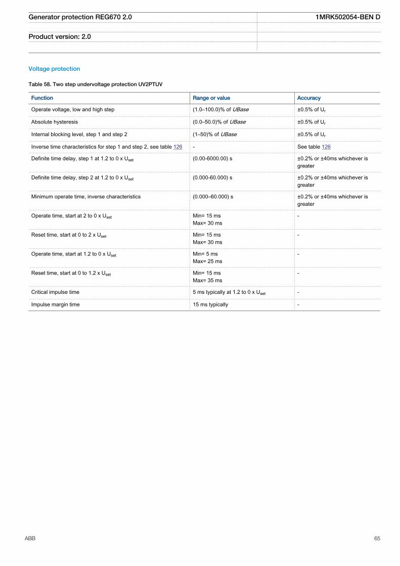
Voltage protection
Table 58. Two step undervoltage protection UV2PTUV
Function Range or value Accuracy
Operate voltage, low and high step (1.0–100.0)% of UBase ±0.5% of Ur
Absolute hysteresis (0.0–50.0)% of UBase ±0.5% of Ur
Internal blocking level, step 1 and step 2 (1–50)% of UBase ±0.5% of Ur
Inverse time characteristics for step 1 and step 2, see table 126 - See table 126
Definite time delay, step 1 at 1.2 to 0 x Uset (0.00-6000.00) s ±0.2% or ±40ms whichever isgreater
Definite time delay, step 2 at 1.2 to 0 x Uset (0.000-60.000) s ±0.2% or ±40ms whichever isgreater
Minimum operate time, inverse characteristics (0.000–60.000) s ±0.2% or ±40ms whichever isgreater
Operate time, start at 2 to 0 x Uset Min= 15 msMax= 30 ms
-
Reset time, start at 0 to 2 x Uset Min= 15 msMax= 30 ms
-
Operate time, start at 1.2 to 0 x Uset Min= 5 msMax= 25 ms
-
Reset time, start at 0 to 1.2 x Uset Min= 15 msMax= 35 ms
-
Critical impulse time 5 ms typically at 1.2 to 0 x Uset -
Impulse margin time 15 ms typically -
Generator protection REG670 2.0 1MRK502054-BEN D
Product version: 2.0
ABB 65

Table 59. Two step overvoltage protection OV2PTOV
Function Range or value Accuracy
Operate voltage, step 1 and 2 (1.0-200.0)% of UBase ±0.5% of Ur at U ≤ Ur±0.5% of U at U > Ur
Absolute hysteresis (0.0–50.0)% of UBase ±0.5% of Ur at U ≤ Ur±0.5% of U at U > Ur
Inverse time characteristics for steps 1 and 2, see table 125 - See table 125
Definite time delay, low step (step 1) at 0 to 1.2 x Uset (0.00 - 6000.00) s ±0.2% or ±45 ms whichever is greater
Definite time delay, high step (step 2) at 0 to 1.2 x Uset (0.000-60.000) s ±0.2% or ±45 ms whichever is greater
Minimum operate time, Inverse characteristics (0.000-60.000) s ±0.2% or ±45 ms whichever is greater
Operate time, start at 0 to 2 x Uset Min. = 15 msMax. = 30 ms
-
Reset time, start at 2 to 0 x Uset Min. = 15 msMax. = 30 ms
-
Operate time, start at 0 to 1.2 x Uset Min. = 20 msMax. = 35 ms
-
Reset time, start at 1.2 to 0 x Uset Min. = 5 msMax. = 25 ms
-
Critical impulse time 10 ms typically at 0 to 2 x Uset -
Impulse margin time 15 ms typically -
Table 60. Two step residual overvoltage protection ROV2PTOV
Function Range or value Accuracy
Operate voltage, step 1 and step 2 (1.0-200.0)% of UBase ± 0.5% of Ur at U ≤ Ur± 0.5% of U at U > Ur
Absolute hysteresis (0.0–50.0)% of UBase ± 0.5% of Ur at U ≤ Ur± 0.5% of U at U > Ur
Inverse time characteristics for low and high step, see table 127 - See table 127
Definite time delay low step (step 1) at 0 to 1.2 x Uset (0.00–6000.00) s ± 0.2% or ± 45 ms whichever isgreater
Definite time delay high step (step 2) at 0 to 1.2 x Uset (0.000–60.000) s ± 0.2% or ± 45 ms whichever isgreater
Minimum operate time (0.000-60.000) s ± 0.2% or ± 45 ms whichever isgreater
Operate time, start at 0 to 2 x Uset Min. = 15 msMax. = 30 ms
-
Reset time, start at 2 to 0 x Uset Min. = 15 msMax. = 30 ms
-
Operate time, start at 0 to 1.2 x Uset Min. = 20 msMax. = 35 ms
-
Reset time, start at 1.2 to 0 x Uset Min. = 5 msMax. = 25 ms
-
Critical impulse time 10 ms typically at 0 to 2 x Uset -
Impulse margin time 15 ms typically -
Generator protection REG670 2.0 1MRK502054-BEN D
Product version: 2.0
66 ABB

Table 61. Overexcitation protection OEXPVPH
Function Range or value Accuracy
Operate value, start (100–180)% of (UBase/frated) ± 0.5% of U
Operate value, alarm (50–120)% of start level ± 0.5% of Ur at U ≤ Ur± 0.5% of U at U > Ur
Operate value, high level (100–200)% of (UBase/frated) ± 0.5% of U
Curve type IEEE or customer defined
2
(0.18 ):
( 1)k
IEEE tM
×=
-
EQUATION1319 V1 EN (Equation 2)
where M = (E/f)/(Ur/fr)
± 5.0 % or ± 45 ms, whichever is greater
Minimum time delay for inversefunction
(0.000–60.000) s ± 1.0% or ± 45 ms, whichever is greater
Maximum time delay for inversefunction
(0.00–9000.00) s ± 1.0% or ± 45 ms, whichever is greater
Alarm time delay (0.00–9000.00) ± 1.0% or ± 45 ms, whichever is greater
Table 62. Voltage differential protection VDCPTOV
Function Range or value Accuracy
Voltage difference for alarm andtrip
(2.0–100.0) % of UBase ±0.5% of Ur
Under voltage level (1.0–100.0) % of UBase ±0.5% of Ur
Independent time delay forvoltage differential alarm at 0.8 to1.2 x UDAlarm
(0.000–60.000)s ±0.2% or ±40 ms whichever is greater
Independent time delay forvoltage differential trip at 0.8 to 1.2x UDTrip
(0.000–60.000)s ±0.2% or ±40 ms whichever is greater
Independent time delay forvoltage differential reset at 1.2 to0.8 x UDTrip
(0.000–60.000)s ±0.2% or ±40 ms whichever is greater
Generator protection REG670 2.0 1MRK502054-BEN D
Product version: 2.0
ABB 67
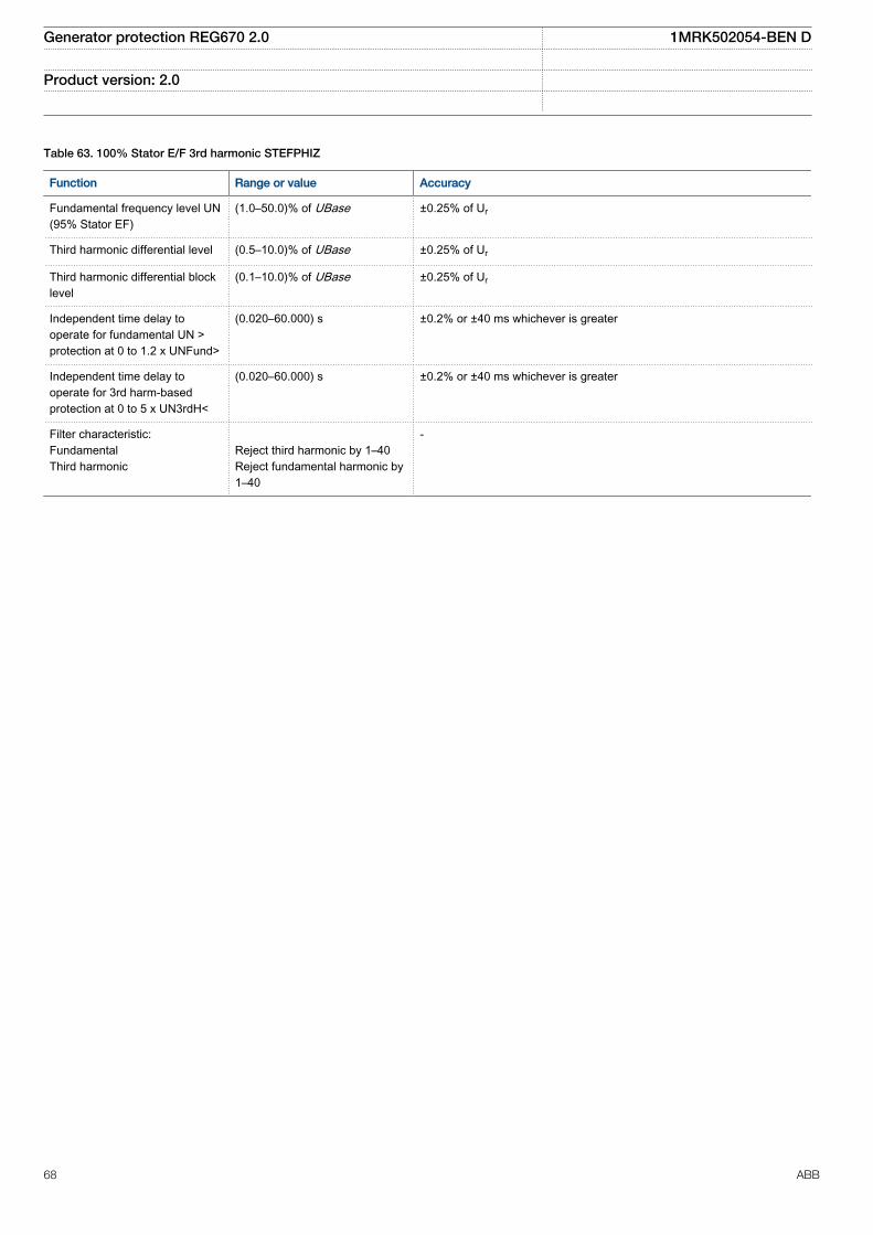
Table 63. 100% Stator E/F 3rd harmonic STEFPHIZ
Function Range or value Accuracy
Fundamental frequency level UN(95% Stator EF)
(1.0–50.0)% of UBase ±0.25% of Ur
Third harmonic differential level (0.5–10.0)% of UBase ±0.25% of Ur
Third harmonic differential blocklevel
(0.1–10.0)% of UBase ±0.25% of Ur
Independent time delay tooperate for fundamental UN >protection at 0 to 1.2 x UNFund>
(0.020–60.000) s ±0.2% or ±40 ms whichever is greater
Independent time delay tooperate for 3rd harm-basedprotection at 0 to 5 x UN3rdH<
(0.020–60.000) s ±0.2% or ±40 ms whichever is greater
Filter characteristic:FundamentalThird harmonic
Reject third harmonic by 1–40Reject fundamental harmonic by1–40
-
Generator protection REG670 2.0 1MRK502054-BEN D
Product version: 2.0
68 ABB

Frequency protection
Table 64. Underfrequency protection SAPTUF
Function Range or value Accuracy
Operate value, start function, at symmetrical threephase voltage
(35.00-75.00) Hz ± 2.0 mHz
Operate time, start at fset + 0.02 Hz to fset - 0.02 Hzfn = 50 Hz
Min. = 80 ms
-Max. = 95 ms
fn = 60 HzMin. = 65 ms
Max. = 80 ms
Reset time, start at fset - 0.02 Hz to fset + 0.02 Hz Min. = 15 msMax. = 30 ms -
Operate time, definite time function at fset + 0.02 Hz tofset - 0.02 Hz
(0.000-60.000)s ± 0.2% or ± 100 ms whichever is greater
Reset time, definite time function at fset - 0.02 Hz to fset+ 0.02 Hz
(0.000-60.000)s ± 0.2% or ± 120 ms whichever is greater
Voltage dependent time delay Settings:UNom=(50-150)% of UbaseUMin=(50-150)% of UbaseExponent=0.0-5.0tMax=(0.010–60.000)stMin=(0.010–60.000)s
± 1.0% or ± 120 ms whichever is greater
( )ExponentU UMin
t tMax tMin tMinUNom UMin
-= × - +
-é ùê úë û
EQUATION1182 V1 EN (Equation 3)
U=Umeasured
Table 65. Overfrequency protection SAPTOF
Function Range or value Accuracy
Operate value, start function at symmetrical three-phase voltage (35.00-90.00) Hz ± 2.0 mHz
Operate time, start at fset - 0.02 Hz to fset + 0.02 Hz fn = 50Hz Min. = 80 msMax. = 95 ms
-
fn = 60 Hz Min. = 65 msMax. = 80 ms
Reset time, start at fset + 0.02 Hz to fset - 0.02 Hz Min. = 15 msMax. = 30 ms
-
Operate time, definite time function at fset -0.02 Hz to fset + 0.02 Hz (0.000-60.000)s ± 0.2% ± 100 mswhichever is greater
Reset time, definite time function at fset + 0.02 Hz to fset - 0.02 Hz (0.000-60.000)s ± 0.2% ± 120 ms,whichever is greater
Generator protection REG670 2.0 1MRK502054-BEN D
Product version: 2.0
ABB 69

Table 66. Rate-of-change frequency protection SAPFRC
Function Range or value Accuracy
Operate value, start function (-10.00-10.00) Hz/s ±10.0 mHz/s
Operate value, restore enable frequency (45.00-65.00) Hz ±2.0 mHz
Definite restore time delay (0.000-60.000) s ±0.2% or ±100 ms whichever isgreater
Definite time delay for frequency gradient trip (0.200-60.000) s ±0.2% or ±120 ms whichever isgreater
Definite reset time delay (0.000-60.000) s ±0.2% or ±250 ms whichever isgreater
Table 67. Frequency accumulation protection FTAQFVR
Function Range or value Accuracy
Operate value, frequency high limit level atsymmetrical three phase voltage
(35.00 – 90.00) Hz ±2.0 mHz
Operatevalue, frequency low limit level atsymmetrical three phase voltage
(30.00 – 85.00) Hz ±2.0 mHz
Operate value, voltage high and low limit forvoltage band limit check
(0.0 – 200.0)% of UBase ±0.5% of Ur at U ≤ Ur±0.5% of U at U > Ur
Operate value, current start level (5.0 – 100.0)% of IBase ±1.0% of Ir or 0.01 A at I≤Ir
Independent time delay for the continuous timelimit at fset+0.02 Hz to fset-0.02 Hz
(0.0 – 6000.0) s ±0.2% or ±200 ms whichever is greater
Independent time delay for the accumulationtime limit at fset+0.02 Hz to fset-0.02 Hz
(10.0 – 90000.0) s ±0.2% or ±200 ms whichever is greater
Generator protection REG670 2.0 1MRK502054-BEN D
Product version: 2.0
70 ABB

Multipurpose protection
Table 68. General current and voltage protection CVGAPC
Function Range or value Accuracy
Measuring current input phase1, phase2, phase3, PosSeq, -NegSeq, -3*ZeroSeq, MaxPh, MinPh,UnbalancePh, phase1-phase2, phase2-phase3, phase3-phase1, MaxPh-Ph,MinPh-Ph, UnbalancePh-Ph
-
Measuring voltage input phase1, phase2, phase3, PosSeq, -NegSeq, -3*ZeroSeq, MaxPh, MinPh,UnbalancePh, phase1-phase2, phase2-phase3, phase3-phase1, MaxPh-Ph,MinPh-Ph, UnbalancePh-Ph
-
Start overcurrent, step 1 - 2 (2 - 5000)% of IBase ±1.0% of Ir at I ≤ Ir±1.0% of I at I > Ir
Start undercurrent, step 1 - 2 (2 - 150)% of IBase ±1.0% of Ir at I ≤ Ir±1.0% of I at I > Ir
Independent time delay, overcurrent at 0 to 2 x Iset, step 1 - 2 (0.00 - 6000.00) s ±0.2% or ±35 ms whichever isgreater
Independent time delay, undercurrent at 2 to 0 x Iset, step 1 - 2 (0.00 - 6000.00) s ±0.2% or ±35 ms whichever isgreater
Overcurrent (non-directional):
Start time at 0 to 2 x Iset Min. = 15 msMax. = 30 ms
-
Reset time at 2 to 0 x Iset Min. = 15 msMax. = 30 ms
-
Start time at 0 to 10 x Iset Min. = 5 msMax. = 20 ms
-
Reset time at 10 to 0 x Iset Min. = 20 msMax. = 35 ms
-
Undercurrent:
Start time at 2 to 0 x Iset Min. = 15 msMax. = 30 ms
-
Reset time at 0 to 2 x Iset Min. = 15 msMax. = 30 ms
-
Overcurrent:
Inverse time characteristics, see table 122, 123 and table "" 16 curve types See table 122, 123 and table ""
Overcurrent:
Minimum operate time for inverse curves, step 1 - 2 (0.00 - 6000.00) s ±0.2% or ±35 ms whichever isgreater
Voltage level where voltage memory takes over (0.0 - 5.0)% of UBase ±0.5% of Ur
Start overvoltage, step 1 - 2 (2.0 - 200.0)% of UBase ±0.5% of Ur at U ≤ Ur±0.5% of U at U > Ur
Start undervoltage, step 1 - 2 (2.0 - 150.0)% of UBase ±0.5% of Ur at U ≤ Ur±0.5% of U at U > Ur
Independent time delay, overvoltage at 0.8 to 1.2 x Uset, step 1 - 2 (0.00 - 6000.00) s ±0.2% or ±35 ms whichever isgreater
Generator protection REG670 2.0 1MRK502054-BEN D
Product version: 2.0
ABB 71
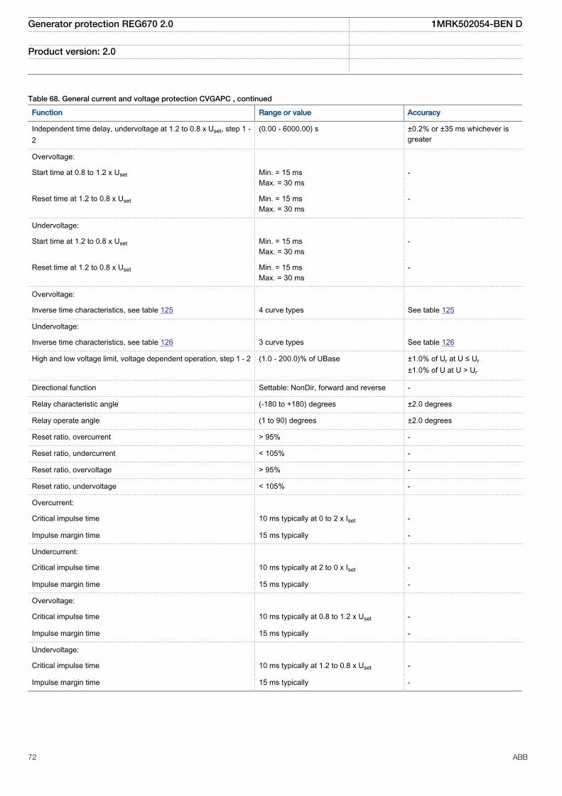
Table 68. General current and voltage protection CVGAPC , continued
Function Range or value Accuracy
Independent time delay, undervoltage at 1.2 to 0.8 x Uset, step 1 -2
(0.00 - 6000.00) s ±0.2% or ±35 ms whichever isgreater
Overvoltage:
Start time at 0.8 to 1.2 x Uset Min. = 15 msMax. = 30 ms
-
Reset time at 1.2 to 0.8 x Uset Min. = 15 msMax. = 30 ms
-
Undervoltage:
Start time at 1.2 to 0.8 x Uset Min. = 15 msMax. = 30 ms
-
Reset time at 1.2 to 0.8 x Uset Min. = 15 msMax. = 30 ms
-
Overvoltage:
Inverse time characteristics, see table 125 4 curve types See table 125
Undervoltage:
Inverse time characteristics, see table 126 3 curve types See table 126
High and low voltage limit, voltage dependent operation, step 1 - 2 (1.0 - 200.0)% of UBase ±1.0% of Ur at U ≤ Ur±1.0% of U at U > Ur
Directional function Settable: NonDir, forward and reverse -
Relay characteristic angle (-180 to +180) degrees ±2.0 degrees
Relay operate angle (1 to 90) degrees ±2.0 degrees
Reset ratio, overcurrent > 95% -
Reset ratio, undercurrent < 105% -
Reset ratio, overvoltage > 95% -
Reset ratio, undervoltage < 105% -
Overcurrent:
Critical impulse time 10 ms typically at 0 to 2 x Iset -
Impulse margin time 15 ms typically -
Undercurrent:
Critical impulse time 10 ms typically at 2 to 0 x Iset -
Impulse margin time 15 ms typically -
Overvoltage:
Critical impulse time 10 ms typically at 0.8 to 1.2 x Uset -
Impulse margin time 15 ms typically -
Undervoltage:
Critical impulse time 10 ms typically at 1.2 to 0.8 x Uset -
Impulse margin time 15 ms typically -
Generator protection REG670 2.0 1MRK502054-BEN D
Product version: 2.0
72 ABB
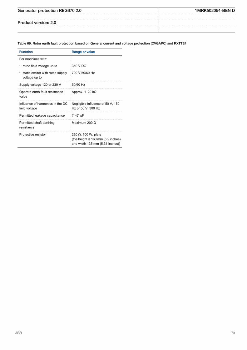
Table 69. Rotor earth fault protection based on General current and voltage protection (CVGAPC) and RXTTE4
Function Range or value
For machines with:
• rated field voltage up to 350 V DC
• static exciter with rated supplyvoltage up to
700 V 50/60 Hz
Supply voltage 120 or 230 V 50/60 Hz
Operate earth fault resistancevalue
Approx. 1–20 kΩ
Influence of harmonics in the DCfield voltage
Negligible influence of 50 V, 150Hz or 50 V, 300 Hz
Permitted leakage capacitance (1–5) μF
Permitted shaft earthingresistance
Maximum 200 Ω
Protective resistor 220 Ω, 100 W, plate(the height is 160 mm (6,2 inches)and width 135 mm (5,31 inches))
Generator protection REG670 2.0 1MRK502054-BEN D
Product version: 2.0
ABB 73

Table 70. Voltage-restrained time overcurrent protection VRPVOC
Function Range or value Accuracy
Start overcurrent (2.0 - 5000.0)% of IBase ±1.0% of Ir at I ≤ Ir±1.0% of I at I > Ir
Reset ratio, overcurrent > 95% -
Operate time, start overcurrent at 0 to 2 x Iset Min. = 15 ms -
Max. = 30 ms
Reset time, start overcurrent at 2 to 0 x Iset Min. = 15 ms -
Max. = 30 ms
Operate time, start overcurrent at 0 to 10 x Iset Min. = 5 msMax. = 20 ms
-
Reset time, start overcurrent at 10 to 0 x Iset Min. = 20 msMax. = 35 ms
-
Independent time delay to operate at 0 to 2 x Iset (0.00 - 6000.00) s ±0.2% or ±35 ms whichever isgreater
Inverse time characteristics,see tables 122 and 123
13 curve types See tables 122 and 123
Minimum operate time for inverse time characteristics (0.00 - 60.00) s ±0.2% or ±35 ms whichever isgreater
High voltage limit, voltage dependent operation (30.0 - 100.0)% of UBase ±1.0% of Ur
Start undervoltage (2.0 - 100.0)% of UBase ±0.5% of Ur
Reset ratio, undervoltage < 105% -
Operate time start undervoltage at 2 to 0 x Uset Min. = 15 ms -
Max. = 30 ms
Reset time start undervoltage at 0 to 2 x Uset Min. = 15 ms -
Max. = 30 ms
Independent time delay to operate, undervoltage at 2 to 0 x Uset (0.00 - 6000.00) s ±0.2% or ±35 ms whichever isgreater
Internal low voltage blocking (0.0 - 5.0)% of UBase ±0.25% of Ur
Overcurrent:Critical impulse timeImpulse margin time
10 ms typically at 0 to 2 x Iset15 ms typically
-
Undervoltage:Critical impulse timeImpulse margin time
10ms typically at 2 to 0 x Uset15 ms typically
-
Generator protection REG670 2.0 1MRK502054-BEN D
Product version: 2.0
74 ABB

Secondary system supervision
Table 71. Current circuit supervision CCSSPVC
Function Range or value Accuracy
Operate current (10-200)% of IBase ±10.0% of Ir at I ≤ Ir±10.0% of I at I > Ir
Reset ratio, Operate current >90%
Block current (20-500)% of IBase ±5.0% of Ir at I ≤ Ir±5.0% of I at I > Ir
Reset ratio, Block current >90% at (50-500)% of IBase
Table 72. Fuse failure supervision FUFSPVC
Function Range or value Accuracy
Operate voltage, zero sequence (1-100)% of UBase ± 0.5% of Ur
Operate current, zero sequence (1–100)% of IBase ± 0.5% of Ir
Operate voltage, negative sequence (1-100)% of UBase 0.5% of Ur
Operate current, negative sequence (1–100)% of IBase ± 0.5% of Ir
Operate voltage change level (1-100)% of UBase ± 10.0% of Ur
Operate current change level (1–100)% of IBase ± 10.0% of Ir
Operate phase voltage (1-100)% of UBase ± 0.5% of Ur
Operate phase current (1–100)% of IBase ± 0.5% of Ir
Operate phase dead line voltage (1-100)% of UBase ± 0.5% of Ur
Operate phase dead line current (1–100)% of IBase ± 0.5% of Ir
Operate time, start, 1 ph, at 1 to 0 x Ur Min. = 10 msMax. = 25 ms
-
Reset time, start, 1 ph, at 0 to 1 x Ur Min. = 15 msMax. = 30 ms
-
Generator protection REG670 2.0 1MRK502054-BEN D
Product version: 2.0
ABB 75

Table 73. Fuse failure supervision VDSPVC
Function Range or value Accuracy
Operate value, block of main fusefailure
(10.0-80.0)% of UBase ±0.5% of Ur
Reset ratio <110%
Operate time, block of main fusefailure at 1 to 0 x Ur
Min. = 5 ms –
Max. = 15 ms
Reset time, block of main fusefailure at 0 to 1 x Ur
Min. = 15 ms –
Max. = 30 ms
Operate value, alarm for pilot fusefailure
(10.0-80.0)% of UBase ±0.5% of Ur
Reset ratio <110% –
Operate time, alarm for pilot fusefailure at 1 to 0 x Ur
Min. = 5 ms –
Max. = 15 ms
Reset time, alarm for pilot fusefailure at 0 to 1 x Ur
Min. = 15 ms –
Max. = 30 ms
Generator protection REG670 2.0 1MRK502054-BEN D
Product version: 2.0
76 ABB

Control
Table 74. Synchronizing, synchrocheck and energizing check SESRSYN
Function Range or value Accuracy
Phase shift, jline - jbus (-180 to 180) degrees -
Voltage high limit for synchronizing and synchrocheck (50.0-120.0)% of UBase ± 0.5% of Ur at U ≤ Ur± 0.5% of U at U > Ur
Reset ratio, synchrocheck > 95% -
Frequency difference limit between bus and line for synchrocheck (0.003-1.000) Hz ± 2.5 mHz
Phase angle difference limit between bus and line for synchrocheck (5.0-90.0) degrees ± 2.0 degrees
Voltage difference limit between bus and line for synchronizing andsynchrocheck
(0.02-0.5) p.u ± 0.5% of Ur
Time delay output for synchrocheck when angle difference between busand line jumps from “PhaseDiff” + 2 degrees to “PhaseDiff” - 2 degrees
(0.000-60.000) s ± 0.2% or ± 35 ms whichever isgreater
Frequency difference minimum limit for synchronizing (0.003-0.250) Hz ± 2.5 mHz
Frequency difference maximum limit for synchronizing (0.050-0.500) Hz ± 2.5 mHz
Maximum allowed frequency rate of change (0.000-0.500) Hz/s ± 10.0 mHz/s
Breaker closing pulse duration (0.050-60.000) s ± 0.2% or ± 15 ms whichever isgreater
tMaxSynch, which resets synchronizing function if no close has been madebefore set time
(0.000-6000.00) s ± 0.2% or ± 35 ms whichever isgreater
Minimum time to accept synchronizing conditions (0.000-60.000) s ± 0.2% or ± 35 ms whichever isgreater
Voltage high limit for energizing check (50.0-120.0)% of UBase ± 0.5% of Ur at U ≤ Ur± 0.5% of U at U > Ur
Reset ratio, voltage high limit > 95% -
Voltage low limit for energizing check (10.0-80.0)% of UBase ± 0.5% of Ur
Reset ratio, voltage low limit < 105% -
Maximum voltage for energizing (50.0-180.0)% of UBase ± 0.5% of Ur at U ≤ Ur± 0.5% of U at U > Ur
Time delay for energizing check when voltage jumps from 0 to 90% ofUrated
(0.000-60.000) s ± 0.2% or ± 100 ms whichever isgreater
Operate time for synchrocheck function when angle difference between busand line jumps from “PhaseDiff” + 2 degrees to “PhaseDiff” - 2 degrees
Min = 15 msMax = 30 ms
–
Operate time for energizing function when voltage jumps from 0 to 90% ofUrated
Min = 70 msMax = 90 ms
–
Generator protection REG670 2.0 1MRK502054-BEN D
Product version: 2.0
ABB 77

Table 75. Voltage control TCMYLTC and TLCYLTC
Function Range or value Accuracy
Transformer reactance (0.1–200.0)Ω, primary -
Time delay for lower command when fast step down mode is activated (1.0–100.0) s -
Voltage control set voltage (85.0–120.0)% of UBase ± 0.25 % of Ur
Outer voltage deadband (0.2–9.0)% of UBase -
Inner voltage deadband (0.1–9.0)% of UBase -
Upper limit of busbar voltage (80–180)% of UBase ± 0.5% of Ur
Lower limit of busbar voltage (70–120)% of UBase ± 0.5% of Ur
Undervoltage block level (50–120)% of UBase ± 0.5% of Ur
Time delay (long) for automatic control commands (3–1000) s ± 0.2% or ± 600 mswhichever is greater
Time delay (short) for automatic control commands (1–1000) s ± 0.2% or ± 600 mswhichever is greater
Minimum operating time in inverse mode (3–120) s ± 0.2% or ± 600 mswhichever is greater
Line resistance (0.00–150.00)Ω, primary -
Line reactance (-150.00–150.00)Ω, primary -
Load voltage adjustment constants (-20.0–20.0)% of UBase -
Load voltage auto correction (-20.0–20.0)% of UBase -
Duration time for the reverse action block signal (30–6000) s ± 0.2% or ± 600 mswhichever is greater
Current limit for reverse action block (0–100)% of I1Base -
Overcurrent block level (5–250)% of I1Base ± 1.0% of Ir at I≤Ir± 1.0% of I at I>Ir
Level for number of counted raise/lower within one hour (0–30) operations/hour -
Level for number of counted raise/lower within 24 hours (0–100) operations/day -
Time window for hunting alarm (1–120) minutes -
Hunting detection alarm, max operations/window (3–30) operations/window -
Alarm level of active power in forward and reverse direction at (10-200)% ofSr and (85-120)% of UBase
(-9999.99–9999.99) MW ± 1.0% of Sr
Alarm level of reactive power in forward and reverse direction at (10-200)%of Sr and (85-120)% of UBase
(-9999.99–9999.99) MVAr ± 1.0% of Sr
Time delay for alarms from power supervision (1–6000) s ± 0.2% or ± 600 mswhichever is greater
Tap position for lowest and highest voltage (1–63) -
mA for lowest and highest voltage tap position (0.000–25.000) mA -
Type of code conversion BIN, BCD, GRAY, SINGLE, mA -
Generator protection REG670 2.0 1MRK502054-BEN D
Product version: 2.0
78 ABB
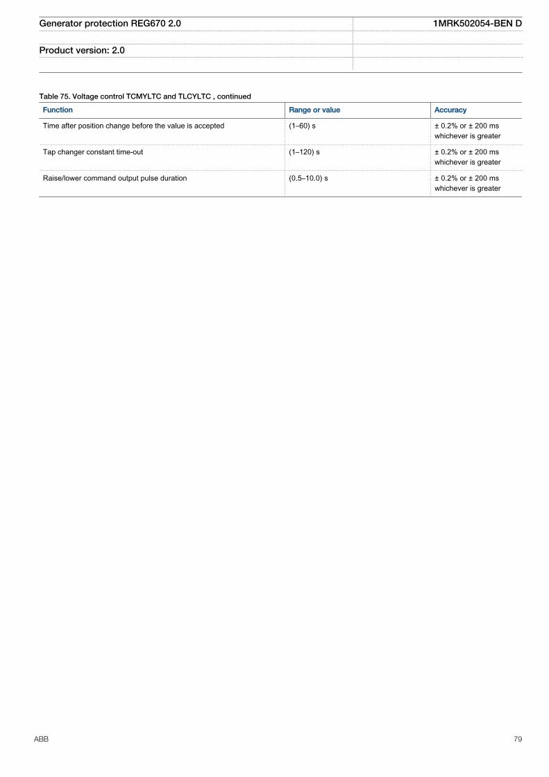
Table 75. Voltage control TCMYLTC and TLCYLTC , continued
Function Range or value Accuracy
Time after position change before the value is accepted (1–60) s ± 0.2% or ± 200 mswhichever is greater
Tap changer constant time-out (1–120) s ± 0.2% or ± 200 mswhichever is greater
Raise/lower command output pulse duration (0.5–10.0) s ± 0.2% or ± 200 mswhichever is greater
Generator protection REG670 2.0 1MRK502054-BEN D
Product version: 2.0
ABB 79

Logic
Table 76. Tripping logic common 3-phase output SMPPTRC
Function Range or value Accuracy
Trip action 3-ph, 1/3-ph, 1/2/3-ph -
Minimum trip pulse length (0.000-60.000) s ± 0.2% or ± 30 ms whichever is greater
3-pole trip delay (0.020-0.500) s ± 0.2% or ±10 ms whichever is greater
Single phase delay, two phasedelay and evolving fault delay
(0.000-60.000) s ± 0.2% or ±10 ms whichever is greater
Table 77. Configurable logic blocks
Logic block Quantity with cycle time Range or value Accuracy
fast medium normal
LogicAND 60 60 160 - -
LogicOR 60 60 160 - -
LogicXOR 10 10 20 - -
LogicInverter 30 30 80 - -
LogicSRMemory 10 10 20 - -
LogicRSMemory 10 10 20 - -
LogicGate 10 10 20 - -
LogicTimer 10 10 20 (0.000–90000.000) s ± 0.5% ± 10 ms
LogicPulseTimer 10 10 20 (0.000–90000.000) s ± 0.5% ± 10 ms
LogicTimerSet 10 10 20 (0.000–90000.000) s ± 0.5% ± 10 ms
LogicLoopDelay 10 10 20 (0.000–90000.000) s ± 0.5% ± 10 ms
Trip Matrix Logic 6 6 - - -
Boolean 16 to Integer 4 4 8 - -
Boolean 16 to integerwith Logic Node
4 4 8 - -
Integer to Boolean 16 4 4 8 - -
Integer to Boolean 16with Logic Node
4 4 8 - -
Generator protection REG670 2.0 1MRK502054-BEN D
Product version: 2.0
80 ABB

Table 78. Configurable logic blocks Q/T
Logic block Quantity with cycle time Range or value Accuracy
medium normal
ANDQT 20 100 - -
ORQT 20 100 - -
INVERTERQT 20 100 - -
XORQT 10 30 - -
SRMEMORYQT 10 30 - -
RSMEMORYQT 10 30 - -
TIMERSETQT 10 30 (0.000-90000.000) s ± 0.5% ± 10 ms
PULSETIMERQT 10 30 (0.000-90000.000) s ± 0.5% ± 10 ms
INVALIDQT 6 6 - -
INDCOMBSPQT 10 10 - -
INDEXTSPQT 10 10 - -
Table 79. IntegratorTIGAPC
Function Cycle time(ms)
Range ofvalue
Accuracy
Time integrationcontinuousactive 3
0-999999.99s
±0.2% or ±20 mswhichever is greater
Time integrationcontinuousactive
8 0-999999.99s
± 0.2% or ±50 mswhichever is greater
Table 79. IntegratorTIGAPC , continued
Function Cycle time(ms)
Range ofvalue
Accuracy
Time integrationcontinuousactive
100 0-999999.99s
±0.2% or ±250 mswhichever is greater
Table 80. Number of TIGAPC instances
Function Quantity with cycle time
3 ms 8 ms 100 ms
TIGAPC - 30 -
Table 81. Elapsed time integrator with limit transgression and overflow supervision TEIGAPC
Function Cycle time (ms) Range or value Accuracy
Elapsed time integration 3 0 ~ 999999.9 s ±0.2% or ±20 ms whichever is greater
8 0 ~ 999999.9 s ±0.2% or ±100 ms whichever isgreater
100 0 ~ 999999.9 s ±0.2% or ±250 ms whichever isgreater
Table 82. Number of TEIGAPC instances
Function Quantity with cycle time
3 ms 8 ms 100 ms
TEIGAPC 4 4 4
Generator protection REG670 2.0 1MRK502054-BEN D
Product version: 2.0
ABB 81

Monitoring
Table 83. Measurements CVMMXN
Function Range or value Accuracy
Frequency (0.95-1.05) × fr ± 2.0 mHz
Voltage (0.1-1.5) ×Ur ± 0.5% of Ur at U£Ur
± 0.5% of U at U > Ur
Connected current (0.2-4.0) × Ir ± 0.5% of Ir at I £ Ir± 0.5% of I at I > Ir
Active power, P 0.1 x Ur< U < 1.5 x Ur0.2 x Ir < I < 4.0 x Ir
± 1.0% of Sr at S ≤ Sr± 1.0% of S at S > SrConditions:0.8 x Ur < U < 1.2 Ur0.2 x Ir < I < 1.2 Ir
Reactive power, Q 0.1 x Ur< U < 1.5 x Ur0.2 x Ir < I < 4.0 x Ir
Apparent power, S 0.1 x Ur < U < 1.5 x Ur0.2 x Ir< I < 4.0 x Ir
Power factor, cos (φ) 0.1 x Ur < U < 1.5 x Ur0.2 x Ir< I < 4.0 x Ir
± 0.02
Table 84. Phase current measurement CMMXU
Function Range or value Accuracy
Current at symmetrical load (0.1-4.0) × Ir ± 0.3% of Ir at I ≤ 0.5 × Ir± 0.3% of I at I > 0.5 × Ir
Phase angle at symmetrical load (0.1-4.0) × Ir ± 1.0° at 0.1 × Ir < I ≤ 0.5 × Ir± 0.5° at 0.5 × Ir < I ≤ 4.0 × Ir
Table 85. Phase-phase voltage measurement VMMXU
Function Range or value Accuracy
Voltage (10 to 300) V ± 0.5% of U at U ≤ 50 V± 0.2% of U at U > 50 V
Phase angle (10 to 300) V ± 0.5° at U ≤ 50 V± 0.2° at U > 50 V
Table 86. Phase-neutral voltage measurement VNMMXU
Function Range or value Accuracy
Voltage (5 to 175) V ± 0.5% of U at U ≤ 50 V± 0.2% of U at U > 50 V
Phase angle (5 to 175) V ± 0.5° at U ≤ 50 V± 0.2° at U > 50 V
Generator protection REG670 2.0 1MRK502054-BEN D
Product version: 2.0
82 ABB

Table 87. Current sequence component measurement CMSQI
Function Range or value Accuracy
Current positive sequence, I1Three phase settings
(0.1–4.0) × Ir ± 0.3% of Ir at I ≤ 0.5 × Ir± 0.3% of I at I > 0.5 × Ir
Current zero sequence, 3I0 Threephase settings
(0.1–1.0) × Ir ± 0.3% of Ir at I ≤ 0.5 × Ir± 0.3% of I at I > 0.5 × Ir
Current negative sequence, I2Three phase settings
(0.1–1.0) × Ir ± 0.3% of Ir at I ≤ 0.5 × Ir± 0.3% of I at I > 0.5 × Ir
Phase angle (0.1–4.0) × Ir ± 1.0° at 0.1 × Ir < I ≤ 0.5 × Ir± 0.5° at 0.5 × Ir < I ≤ 4.0 × Ir
Table 88. Voltage sequence measurement VMSQI
Function Range or value Accuracy
Voltage positive sequence, U1 (10 to 300) V ± 0.5% of U at U ≤ 50 V± 0.2% of U at U > 50 V
Voltage zero sequence, 3U0 (10 to 300) V ± 0.5% of U at U ≤ 50 V± 0.2% of U at U > 50 V
Voltage negative sequence, U2 (10 to 300) V ± 0.5% of U at U ≤ 50 V± 0.2% of U at U > 50 V
Phase angle (10 to 300) V ± 0.5° at U ≤ 50 V± 0.2° at U > 50 V
Table 89. Supervision of mA input signals
Function Range or value Accuracy
mA measuring function ±5, ±10, ±20 mA0-5, 0-10, 0-20, 4-20 mA
±0.1 % of set value ±0.005 mA
Max current of transducer toinput
(-20.00 to +20.00) mA
Min current of transducer toinput
(-20.00 to +20.00) mA
Alarm level for input (-20.00 to +20.00) mA
Warning level for input (-20.00 to +20.00) mA
Alarm hysteresis for input (0.0-20.0) mA
Table 90. Limit counter L4UFCNT
Function Range or value Accuracy
Counter value 0-65535 -
Max. count up speed 30 pulses/s (50% duty cycle) -
Generator protection REG670 2.0 1MRK502054-BEN D
Product version: 2.0
ABB 83

Table 91. Disturbance report DRPRDRE
Function Range or value Accuracy
Pre-fault time (0.05–9.90) s -
Post-fault time (0.1–10.0) s -
Limit time (0.5–10.0) s -
Maximum number of recordings 100, first in - first out -
Time tagging resolution 1 ms See table 118
Maximum number of analog inputs 30 + 10 (external + internallyderived)
-
Maximum number of binary inputs 96 -
Maximum number of phasors in the Trip Value recorder per recording 30 -
Maximum number of indications in a disturbance report 96 -
Maximum number of events in the Event recording per recording 150 -
Maximum number of events in the Event list 1000, first in - first out -
Maximum total recording time (3.4 s recording time and maximum number ofchannels, typical value)
340 seconds (100 recordings) at50 Hz, 280 seconds (80recordings) at 60 Hz
-
Sampling rate 1 kHz at 50 Hz1.2 kHz at 60 Hz
-
Recording bandwidth (5-300) Hz -
Table 92. Event list
Function Value
Buffer capacity Maximum number of events in the list 1000
Resolution 1 ms
Accuracy Depending on time synchronizing
Table 93. Indications
Function Value
Buffer capacity Maximum number of indications presented for single disturbance 96
Maximum number of recorded disturbances 100
Table 94. Event recorder
Function Value
Buffer capacity Maximum number of events in disturbance report 150
Maximum number of disturbance reports 100
Resolution 1 ms
Accuracy Depending on timesynchronizing
Generator protection REG670 2.0 1MRK502054-BEN D
Product version: 2.0
84 ABB
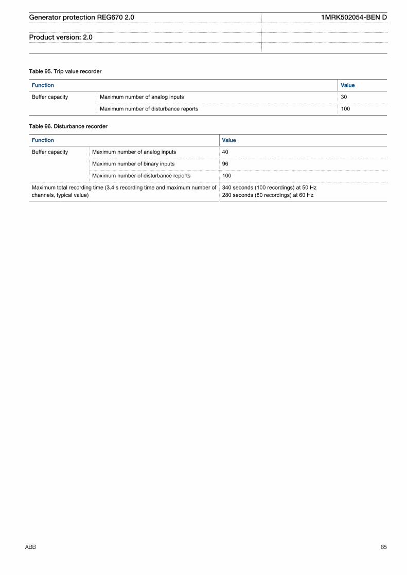
Table 95. Trip value recorder
Function Value
Buffer capacity
Maximum number of analog inputs 30
Maximum number of disturbance reports 100
Table 96. Disturbance recorder
Function Value
Buffer capacity Maximum number of analog inputs 40
Maximum number of binary inputs 96
Maximum number of disturbance reports 100
Maximum total recording time (3.4 s recording time and maximum number ofchannels, typical value)
340 seconds (100 recordings) at 50 Hz280 seconds (80 recordings) at 60 Hz
Generator protection REG670 2.0 1MRK502054-BEN D
Product version: 2.0
ABB 85
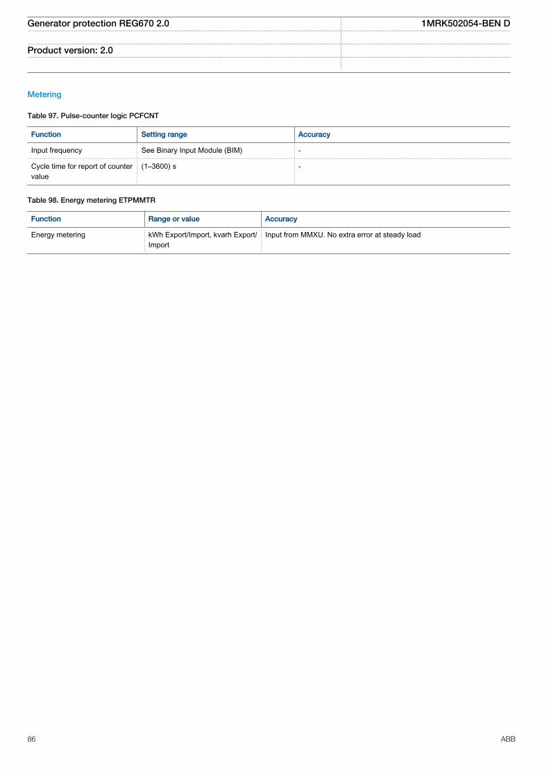
Metering
Table 97. Pulse-counter logic PCFCNT
Function Setting range Accuracy
Input frequency See Binary Input Module (BIM) -
Cycle time for report of countervalue
(1–3600) s -
Table 98. Energy metering ETPMMTR
Function Range or value Accuracy
Energy metering kWh Export/Import, kvarh Export/Import
Input from MMXU. No extra error at steady load
Generator protection REG670 2.0 1MRK502054-BEN D
Product version: 2.0
86 ABB

Station communication
Table 99. Communication protocols
Function Value
Protocol IEC 61850-8-1
Communication speed for the IEDs 100BASE-FX
Protocol IEC 60870–5–103
Communication speed for the IEDs 9600 or 19200 Bd
Protocol DNP3.0
Communication speed for the IEDs 300–19200 Bd
Protocol TCP/IP, Ethernet
Communication speed for the IEDs 100 Mbit/s
Table 100. LON communication protocol
Function Value
Protocol LON
Communication speed 1.25 Mbit/s
Table 101. SPA communication protocol
Function Value
Communication speed 300, 1200, 2400, 4800, 9600, 19200 or 38400 Bd
Slave number 1 to 899
Table 102. IEC 60870-5-103 communication protocol
Function Value
Protocol IEC 60870-5-103
Communication speed 9600, 19200 Bd
Table 103. SLM – LON port
Quantity Range or value
Optical connector Glass fiber: type STPlastic fiber: type HFBR snap-in
Fiber, optical budget Glass fiber: 11 dB (1000m/3000 ft typically *)Plastic fiber: 7 dB (10m/35ft typically *)
Fiber diameter Glass fiber: 62.5/125 mmPlastic fiber: 1 mm
*) depending on optical budget calculation
Generator protection REG670 2.0 1MRK502054-BEN D
Product version: 2.0
ABB 87

Table 104. SLM – SPA/IEC 60870-5-103/DNP3 port
Quantity Range or value
Optical connector Glass fiber: type STPlastic fiber: type HFBR snap-in
Fiber, optical budget Glass fiber: 11 dB (1000m/3000ft m typically *)Plastic fiber: 7 dB (25m/80ft m typically *)
Fiber diameter Glass fiber: 62.5/125 mmPlastic fiber: 1 mm
*) depending on optical budget calculation
Table 105. Galvanic X.21 line data communication module (X.21-LDCM)
Quantity Range or value
Connector, X.21 Micro D-sub, 15-pole male, 1.27 mm (0.050") pitch
Connector, ground selection 2 pole screw terminal
Standard CCITT X21
Communication speed 64 kbit/s
Insulation 1 kV
Maximum cable length 100 m
Table 106. Galvanic RS485 communication module
Quantity Range or value
Communication speed 2400–19200 bauds
External connectors RS-485 6-pole connectorSoft ground 2-pole connector
Table 107. IEC 62439-3 Edition 1 and Edition 2 parallel redundancy protocol
Function Value
Communication speed 100 Base-FX
Generator protection REG670 2.0 1MRK502054-BEN D
Product version: 2.0
88 ABB

Remote communication
Table 108. Line data communication module
Characteristic Range or value
Type of LDCM Short range (SR) Medium range (MR) Long range (LR)
Type of fiber Graded-indexmultimode62.5/125 µm
Singlemode 9/125 µm Singlemode 9/125 µm
Peak Emission Wave lengthNominalMaximumMinimum
820 nm865 nm792 nm
1310 nm1330 nm1290 nm
1550 nm1580 nm1520 nm
Optical budgetGraded-index multimode 62.5/125 mm, Graded-index multimode 50/125 mm
13 dB (typicaldistance about 3km/2 mile *)9 dB (typicaldistance about 2km/1 mile *)
22 dB (typicaldistance 80 km/50mile *)
26 dB (typical distance 110 km/68mile *)
Optical connector Type ST Type FC/PC Type FC/PC
Protocol C37.94 C37.94implementation **)
C37.94 implementation **)
Data transmission Synchronous Synchronous Synchronous
Transmission rate / Data rate 2 Mb/s / 64 kbit/s 2 Mb/s / 64 kbit/s 2 Mb/s / 64 kbit/s
Clock source Internal or derivedfrom receivedsignal
Internal or derivedfrom received signal
Internal or derived from receivedsignal
*) depending on optical budget calculation**) C37.94 originally defined just for multimode; using same header, configuration and data format as C37.94
Generator protection REG670 2.0 1MRK502054-BEN D
Product version: 2.0
ABB 89

HardwareIED
Table 109. Case
Material Steel sheet
Front plate Steel sheet profile with cut-out for HMI
Surface treatment Aluzink preplated steel
Finish Light grey (RAL 7035)
Table 110. Water and dust protection level according to IEC 60529
Front IP40 (IP54 with sealing strip)
Sides, top and bottom IP20
Rear side IP20 with screw compression typeIP10 with ring lug terminals
Table 111. Weight
Case size Weight
6U, 1/2 x 19” £ 10 kg/22 lb
6U, 3/4 x 19” £ 15 kg/33 lb
6U, 1/1 x 19” £ 18 kg/40 lb
Connection system
Table 112. CT and VT circuit connectors
Connector type Rated voltage and current Maximum conductor area
Screw compression type 250 V AC, 20 A 4 mm2 (AWG12)2 x 2.5 mm2 (2 x AWG14)
Terminal blocks suitable for ring lug terminals 250 V AC, 20 A 4 mm2 (AWG12)
Table 113. Auxiliary power supply and binary I/O connectors
Connector type Rated voltage Maximum conductor area
Screw compression type 250 V AC 2.5 mm2 (AWG14)2 × 1 mm2 (2 x AWG18)
Terminal blocks suitable for ring lug terminals 300 V AC 3 mm2 (AWG14)
Because of limitations of space, when ringlug terminal is ordered for Binary I/Oconnections, one blank slot is necessary
between two adjacent IO cards. Please referto the ordering particulars for details.
Generator protection REG670 2.0 1MRK502054-BEN D
Product version: 2.0
90 ABB

Injection equipment hardware
Table 114. Injection unit REX060
Specifications Values
Case size 6U, 1/2 19”; 223.7 x 245 x 267 mm (W x D x H)
Weight 8.0 kg
Burden, binary inputs BI 220 V: burden 0.4 WBI 110 V: burden 0.2 WBI 48 V: burden 0.1 W
Burden, RIM injection < 10 VA at 100 V external disturbance
Burden, SIM injection < 10 VA at 12 V earth fault voltage0 VA at > 10% of maximum earth fault voltage
Burden, SIM injection with REX062 < 1 VA at 24 V earth fault voltage
Burden, measuring transformer SIM < 60 mVA at 24 V; 87 Hz
Burden, measuring transformer RIM < 60 mVA at 50 V; 113 Hz
Installation category III
Pollution degree 2
Table 115. Coupling capacitor unit REX061
Function Range or values Accuracy
For machines with:
• rated field voltage up to 800 V DC -
• static exciter with rated supply voltage upto
1600 V 50/60 Hz -
Specifications Values
Case size 218 x 150 x 243 mm (W x D x H)
Weight 4.8 kg
Assembling 6 x 5 mm screws (3 at bottom and 3 at top)
Rated rotor injection voltage 250 V
Burden, static excitation system X1:1 to X1:7 < 0.5 VA at 100 V external disturbance
Burden, static excitation system X1:1 or X1:7 to 0 V < 1.0 VA at 100 V external disturbance
Burden, brushless excitation system X1:1 and X1:7 to 0 V < 1.5 VA at 100 V external disturbance
Installation category III
Pollution degree 2
Generator protection REG670 2.0 1MRK502054-BEN D
Product version: 2.0
ABB 91
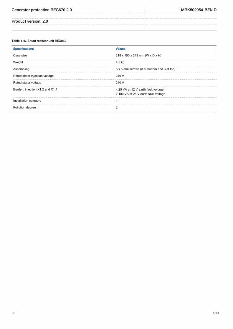
Table 116. Shunt resistor unit REX062
Specifications Values
Case size 218 x 150 x 243 mm (W x D x H)
Weight 4.5 kg
Assembling 6 x 5 mm screws (3 at bottom and 3 at top)
Rated stator injection voltage 240 V
Rated stator voltage 240 V
Burden, injection X1:2 and X1:4 < 25 VA at 12 V earth fault voltage< 100 VA at 24 V earth fault voltage
Installation category III
Pollution degree 2
Generator protection REG670 2.0 1MRK502054-BEN D
Product version: 2.0
92 ABB
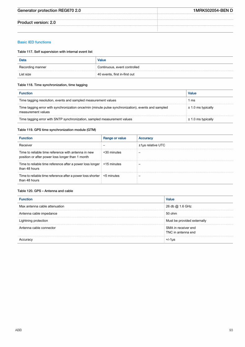
Basic IED functions
Table 117. Self supervision with internal event list
Data Value
Recording manner Continuous, event controlled
List size 40 events, first in-first out
Table 118. Time synchronization, time tagging
Function Value
Time tagging resolution, events and sampled measurement values 1 ms
Time tagging error with synchronization once/min (minute pulse synchronization), events and sampledmeasurement values
± 1.0 ms typically
Time tagging error with SNTP synchronization, sampled measurement values ± 1.0 ms typically
Table 119. GPS time synchronization module (GTM)
Function Range or value Accuracy
Receiver – ±1µs relative UTC
Time to reliable time reference with antenna in newposition or after power loss longer than 1 month
<30 minutes –
Time to reliable time reference after a power loss longerthan 48 hours
<15 minutes –
Time to reliable time reference after a power loss shorterthan 48 hours
<5 minutes –
Table 120. GPS – Antenna and cable
Function Value
Max antenna cable attenuation 26 db @ 1.6 GHz
Antenna cable impedance 50 ohm
Lightning protection Must be provided externally
Antenna cable connector SMA in receiver endTNC in antenna end
Accuracy +/-1μs
Generator protection REG670 2.0 1MRK502054-BEN D
Product version: 2.0
ABB 93

Table 121. IRIG-B
Quantity Rated value
Number of channels IRIG-B 1
Number of optical channels 1
Electrical connector:
Electrical connector IRIG-B BNC
Pulse-width modulated 5 Vpp
Amplitude modulated– low level– high level
1-3 Vpp3 x low level, max 9 Vpp
Supported formats IRIG-B 00x, IRIG-B 12x
Accuracy +/-10μs for IRIG-B 00x and +/-100μs for IRIG-B 12x
Input impedance 100 k ohm
Optical connector:
Optical connector IRIG-B Type ST
Type of fibre 62.5/125 μm multimode fibre
Supported formats IRIG-B 00x
Accuracy +/- 1μs
Generator protection REG670 2.0 1MRK502054-BEN D
Product version: 2.0
94 ABB
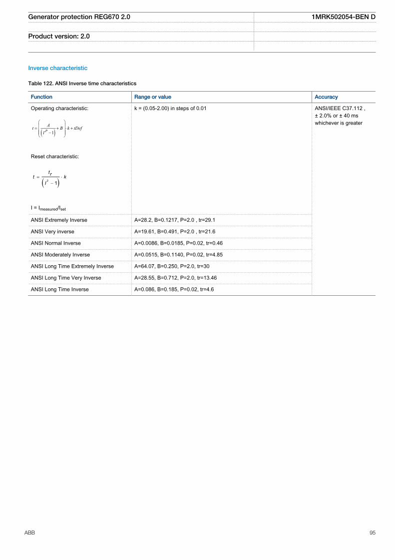
Inverse characteristic
Table 122. ANSI Inverse time characteristics
Function Range or value Accuracy
Operating characteristic:
( )1PAt B k tDef
I
æ öç ÷= + × +ç ÷ç - ÷è ø
EQUATION1249-SMALL V2 EN
Reset characteristic:
( )2 1= ×
-
trt kI
EQUATION1250-SMALL V1 EN
I = Imeasured/Iset
k = (0.05-2.00) in steps of 0.01 ANSI/IEEE C37.112 ,± 2.0% or ± 40 mswhichever is greater
ANSI Extremely Inverse A=28.2, B=0.1217, P=2.0 , tr=29.1
ANSI Very inverse A=19.61, B=0.491, P=2.0 , tr=21.6
ANSI Normal Inverse A=0.0086, B=0.0185, P=0.02, tr=0.46
ANSI Moderately Inverse A=0.0515, B=0.1140, P=0.02, tr=4.85
ANSI Long Time Extremely Inverse A=64.07, B=0.250, P=2.0, tr=30
ANSI Long Time Very Inverse A=28.55, B=0.712, P=2.0, tr=13.46
ANSI Long Time Inverse A=0.086, B=0.185, P=0.02, tr=4.6
Generator protection REG670 2.0 1MRK502054-BEN D
Product version: 2.0
ABB 95

Table 123. IEC Inverse time characteristics
Function Range or value Accuracy
Operating characteristic:
( )1= ×
-
æ öç ÷ç ÷è ø
P
At k
I
EQUATION1251-SMALL V1 EN
I = Imeasured/Iset
k = (0.05-2.00) in steps of 0.01 IEC 60255-151, ± 2.0%or ± 40 ms whichever isgreater
IEC Normal Inverse A=0.14, P=0.02
IEC Very inverse A=13.5, P=1.0
IEC Inverse A=0.14, P=0.02
IEC Extremely inverse A=80.0, P=2.0
IEC Short time inverse A=0.05, P=0.04
IEC Long time inverse A=120, P=1.0
Programmable characteristicOperate characteristic:
( )= + ×
-
æ öç ÷ç ÷è ø
P
At B k
I C
EQUATION1370-SMALL V1 EN
Reset characteristic:
( )= ×
-PR
TRt k
I CR
EQUATION1253-SMALL V1 EN
I = Imeasured/Iset
k = (0.05-999) in steps of 0.01A=(0.005-200.000) in steps of 0.001B=(0.00-20.00) in steps of 0.01C=(0.1-10.0) in steps of 0.1P=(0.005-3.000) in steps of 0.001TR=(0.005-100.000) in steps of 0.001CR=(0.1-10.0) in steps of 0.1PR=(0.005-3.000) in steps of 0.001
Table 124. RI and RD type inverse time characteristics
Function Range or value Accuracy
RI type inverse characteristic
1
0.2360.339
= ×
-
t k
IEQUATION1137-SMALL V1 EN
I = Imeasured/Iset
k = (0.05-2.00) in steps of 0.01 IEC 60255-151, ± 2.0%or ± 40 ms whichever isgreater
RD type logarithmic inverse characteristic
5.8 1.35= - ×æ öç ÷è ø
tI
Ink
EQUATION1138-SMALL V1 EN
I = Imeasured/Iset
k = (0.05-999) in steps of 0.01
Generator protection REG670 2.0 1MRK502054-BEN D
Product version: 2.0
96 ABB

Table 125. Inverse time characteristics for overvoltage protection
Function Range or value Accuracy
Type A curve:
=- >
>
æ öç ÷è ø
tk
U U
U
EQUATION1436-SMALL V1 EN
U> = UsetU = Umeasured
k = (0.05-1.10) in steps of 0.01 ±5.0% or ±45 mswhichever is greater
Type B curve:
2.0
480
32 0.5
=⋅
− >⋅ −
0.035+
>
tk
U U
UEQUATION1437-SMALL V2 EN
k = (0.05-1.10) in steps of 0.01
Type C curve:
3.0
480
32 0.5
=⋅
⋅ −− >
0.035+
>
tk
U U
UEQUATION1438-SMALL V2 EN
k = (0.05-1.10) in steps of 0.01
Programmable curve:
×= +
- >× -
>
æ öç ÷è ø
P
k At D
U UB C
U
EQUATION1439-SMALL V1 EN
k = (0.05-1.10) in steps of 0.01A = (0.005-200.000) in steps of 0.001B = (0.50-100.00) in steps of 0.01C = (0.0-1.0) in steps of 0.1D = (0.000-60.000) in steps of 0.001P = (0.000-3.000) in steps of 0.001
Generator protection REG670 2.0 1MRK502054-BEN D
Product version: 2.0
ABB 97
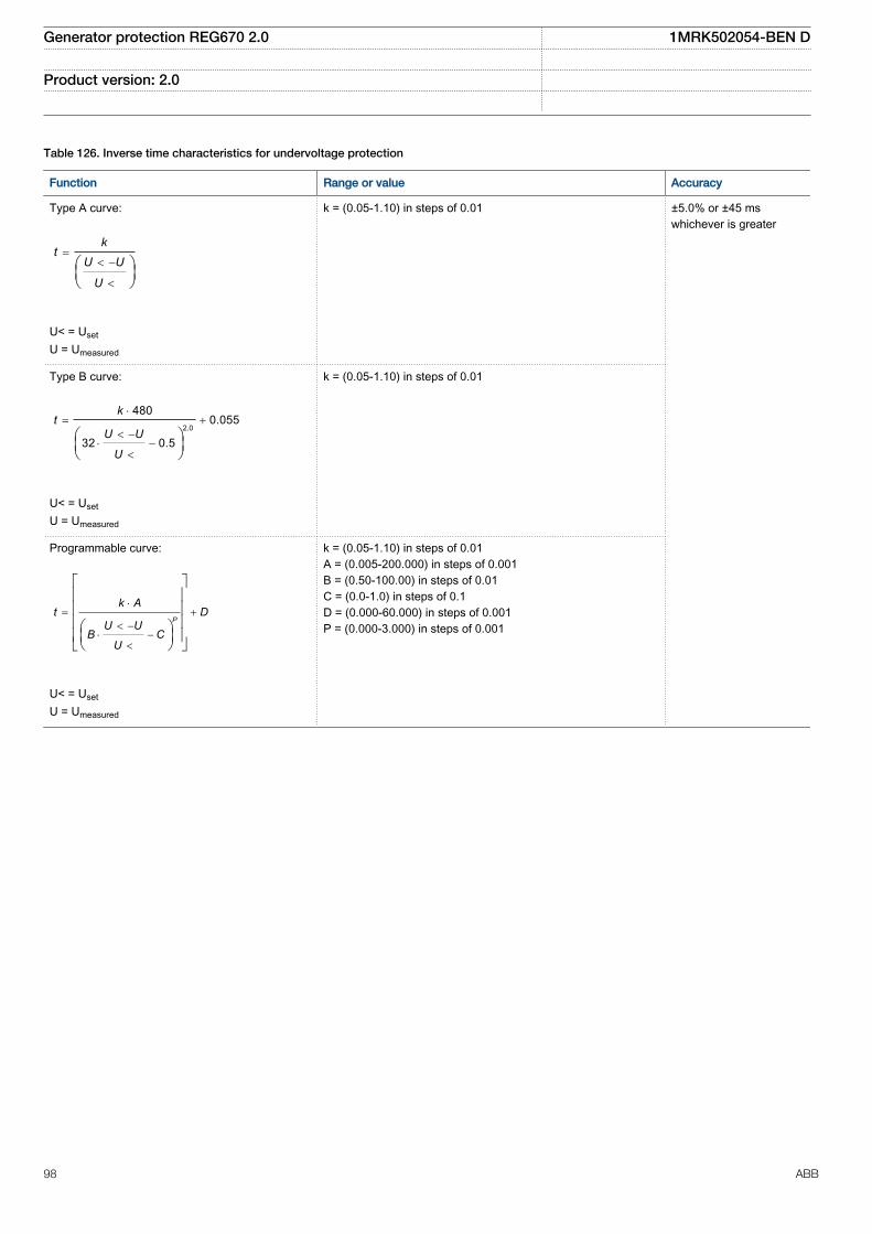
Table 126. Inverse time characteristics for undervoltage protection
Function Range or value Accuracy
Type A curve:
=< -
<
æ öç ÷è ø
kt
U U
U
EQUATION1431-SMALL V1 EN
U< = UsetU = Umeasured
k = (0.05-1.10) in steps of 0.01 ±5.0% or ±45 mswhichever is greater
Type B curve:
2.0
4800.055
32 0.5
×= +
< -× -
<
æ öç ÷è ø
kt
U U
U
EQUATION1432-SMALL V1 EN
U< = UsetU = Umeasured
k = (0.05-1.10) in steps of 0.01
Programmable curve:
×= +
< -× -
<
é ùê úê úê úæ öê úç ÷ë è ø û
P
k At D
U UB C
U
EQUATION1433-SMALL V1 EN
U< = UsetU = Umeasured
k = (0.05-1.10) in steps of 0.01A = (0.005-200.000) in steps of 0.001B = (0.50-100.00) in steps of 0.01C = (0.0-1.0) in steps of 0.1D = (0.000-60.000) in steps of 0.001P = (0.000-3.000) in steps of 0.001
Generator protection REG670 2.0 1MRK502054-BEN D
Product version: 2.0
98 ABB

Table 127. Inverse time characteristics for residual overvoltage protection
Function Range or value Accuracy
Type A curve:
=- >
>
æ öç ÷è ø
tk
U U
U
EQUATION1436-SMALL V1 EN
U> = UsetU = Umeasured
k = (0.05-1.10) in steps of0.01
±5.0% or ±45 ms whichever is greater
Type B curve:
2.0
480
32 0.5
=⋅
− >⋅ −
0.035+
>
tk
U U
U
EQUATION1437-SMALL V2 EN
k = (0.05-1.10) in steps of0.01
Type C curve:
3.0
480
32 0.5
=⋅
⋅ −− >
0.035+
>
tk
U U
U
EQUATION1438-SMALL V2 EN
k = (0.05-1.10) in steps of0.01
Programmable curve:
×= +
- >× -
>
æ öç ÷è ø
P
k At D
U UB C
U
EQUATION1439-SMALL V1 EN
k = (0.05-1.10) in steps of0.01A = (0.005-200.000) insteps of 0.001B = (0.50-100.00) in stepsof 0.01C = (0.0-1.0) in steps of 0.1D = (0.000-60.000) insteps of 0.001P = (0.000-3.000) in stepsof 0.001
Generator protection REG670 2.0 1MRK502054-BEN D
Product version: 2.0
ABB 99

21. Ordering for customized IED
Table 128. General guidelines
GuidelinesCarefully read and follow the set of rules to ensure problem-free order management.Please refer to the available functions table for included application functions.PCM600 can be used to make changes and/or additions to the delivered factory configuration of the pre-configured.
Table 129. Example ordering code
To obtain the complete ordering code, please combine code from the selection tables, as given in the example below.The selected qty of each table must be filled in, if no selection is possible the code is 0Example of a complete code: REG670*2.0-F00X00 - A00002262300000 - B0000040200000000011020111 - C4600262200340004440022311 - D22322100 - E66312 -F9 - S6 - G532 - H12000010044 - K00000000 - L11 - M120 - P01 - B1X0 - AC - KB - B - A3X0 - D1D1ARGN1N1XXXXXXX -AAFXXX - AX
Product definition - Differential protection -REG670* 2.0 - X00 - A 0 0 0 0 0 0 0 0 0 -
Impedance protection -B 0 0 0 0 0 0 0 0 0 0 0 0 0 0 0 -
Current protection -C 00 0 0 00 0 0 0 -
Voltage protection - Frequency protection - Multipurposeprotection
- Generalcalculation
-
D 0 0 - E - F - S -
Secondary system supervision - Control -G - H 0 0 0 0 0 0 0 -
Scheme communication - Logic - Monitoring - Station communication -K 0 0 0 0 0 0 0 0 - L - M 0 - P -
Language
- CasingandMounting
- Connectionandpower
- HMI
- Analog input - Binary input/output -
B1
- - - - - -
Remote end serial communication - Serial communication unit for station communication -
Table 130. Product definition
REG670* 2.0 X00
Table 131. Product definition ordering codes
Product REG670*Software version 2.0Configuration alternativesREG670 Generator protection F00REG670 61850-9-2LE Generator protection N00Selection: ACT configurationNo ACT configuration downloaded X00
Table 132. Differential protection
Position 1 2 3 4 5 6 7 8 9 10 11 12 13 14
A 0 0 0 0 0 0 0 0 0
Generator protection REG670 2.0 1MRK502054-BEN D
Product version: 2.0
100 ABB

Table 133. Differential functions
Function Functionidentification
Ordering no Position
Availableqty
Selectedqty
Notes andrules
Transformer differential protection, two winding T2WPDIF 1MRK005904-FA 5 0-2 Transformer differential protection, three winding T3WPDIF 1MRK005904-GA 6 0-2 1Ph High impedance differential protection HZPDIF 1MRK005904-HA 7 0-6 Generator differential protection GENPDIF 1MRK005904-KA 8 0-2 Restricted earth fault protection, low impedance REFPDIF 1MRK005904-LA 9 0-3
Table 134. Impedance protection
Position
1 2 3 4 5 6 7 8 9 10 11 12 13 14 15 16 17 18 19 20 21 22 23 24 25
B 0 0 0 0 0 0 0 0 0 0 0 0 0 0 0
Table 135. Impedance functions
Note: Only 1 alternative may be selected
Function Functionidentification
Ordering no Position
Availableqty
Selectedqty
Notes andrules
Alternative 3Fullscheme distance protection, mho characteristic ZMHPDIS 1MRK005907-FA 6 0-4 Directional impedance element for mho characteristic ZDMRDIR 1MRK005907-HA 8 0-2 Alternative 5Directional distance protection with phase selection ZMFPDIS 1MRK005907-SA 14 0-1 Alternative 6Directional distance protection with phase selection, seriescompensation
ZMFCPDIS 1MRK005907-RA 15 0-1
Additional options with any alternativePoleSlip/Out-of-step protection PSPPPAM 1MRK005908-CA 19 0-1 Out-of-step protection OOSPPAM 1MRK005908-GA 20 0-1 Loss of excitation LEXPDIS 1MRK005908-BA 21 0-2 Sensitive rotor earth fault protection, injection based ROTIPHIZ 1MRK005908-EA 23 0-1 100% stator earth fault protection, injection based STTIPHIZ 1MRK005908-FA 24 0-1 Underimpedance protection for generators and transformers ZGVPDIS 1MRK005907-TA 25 0-1
Table 136. Current protection
Position
1 2 3 4 5 6 7 8 9 10 11 12 13 14 15 16 17 18 19 20 21 22 23
C 00 0 0 00 0 0 0
Generator protection REG670 2.0 1MRK502054-BEN D
Product version: 2.0
ABB 101
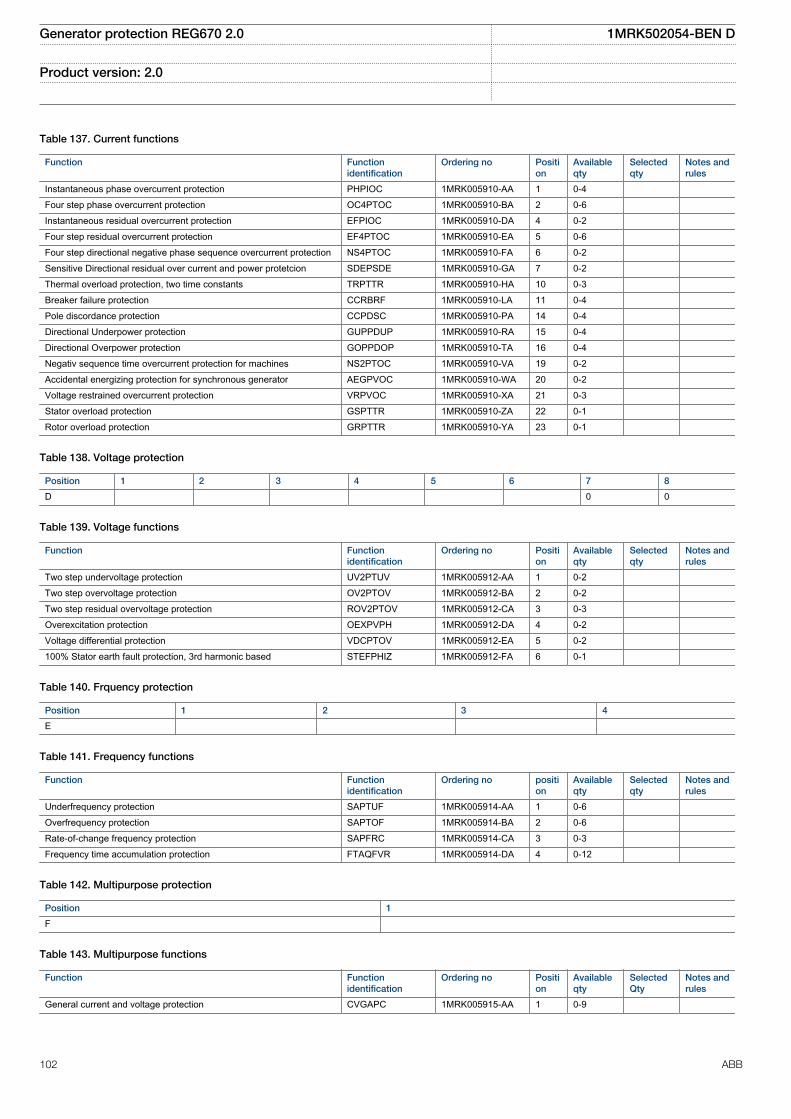
Table 137. Current functions
Function Functionidentification
Ordering no Position
Availableqty
Selectedqty
Notes andrules
Instantaneous phase overcurrent protection PHPIOC 1MRK005910-AA 1 0-4 Four step phase overcurrent protection OC4PTOC 1MRK005910-BA 2 0-6 Instantaneous residual overcurrent protection EFPIOC 1MRK005910-DA 4 0-2 Four step residual overcurrent protection EF4PTOC 1MRK005910-EA 5 0-6 Four step directional negative phase sequence overcurrent protection NS4PTOC 1MRK005910-FA 6 0-2 Sensitive Directional residual over current and power protetcion SDEPSDE 1MRK005910-GA 7 0-2 Thermal overload protection, two time constants TRPTTR 1MRK005910-HA 10 0-3 Breaker failure protection CCRBRF 1MRK005910-LA 11 0-4 Pole discordance protection CCPDSC 1MRK005910-PA 14 0-4 Directional Underpower protection GUPPDUP 1MRK005910-RA 15 0-4 Directional Overpower protection GOPPDOP 1MRK005910-TA 16 0-4 Negativ sequence time overcurrent protection for machines NS2PTOC 1MRK005910-VA 19 0-2 Accidental energizing protection for synchronous generator AEGPVOC 1MRK005910-WA 20 0-2 Voltage restrained overcurrent protection VRPVOC 1MRK005910-XA 21 0-3 Stator overload protection GSPTTR 1MRK005910-ZA 22 0-1 Rotor overload protection GRPTTR 1MRK005910-YA 23 0-1
Table 138. Voltage protection
Position 1 2 3 4 5 6 7 8
D 0 0
Table 139. Voltage functions
Function Functionidentification
Ordering no Position
Availableqty
Selectedqty
Notes andrules
Two step undervoltage protection UV2PTUV 1MRK005912-AA 1 0-2 Two step overvoltage protection OV2PTOV 1MRK005912-BA 2 0-2 Two step residual overvoltage protection ROV2PTOV 1MRK005912-CA 3 0-3 Overexcitation protection OEXPVPH 1MRK005912-DA 4 0-2 Voltage differential protection VDCPTOV 1MRK005912-EA 5 0-2 100% Stator earth fault protection, 3rd harmonic based STEFPHIZ 1MRK005912-FA 6 0-1
Table 140. Frquency protection
Position 1 2 3 4
E
Table 141. Frequency functions
Function Functionidentification
Ordering no position
Availableqty
Selectedqty
Notes andrules
Underfrequency protection SAPTUF 1MRK005914-AA 1 0-6 Overfrequency protection SAPTOF 1MRK005914-BA 2 0-6 Rate-of-change frequency protection SAPFRC 1MRK005914-CA 3 0-3 Frequency time accumulation protection FTAQFVR 1MRK005914-DA 4 0-12
Table 142. Multipurpose protection
Position 1
F
Table 143. Multipurpose functions
Function Functionidentification
Ordering no Position
Availableqty
SelectedQty
Notes andrules
General current and voltage protection CVGAPC 1MRK005915-AA 1 0-9
Generator protection REG670 2.0 1MRK502054-BEN D
Product version: 2.0
102 ABB

Table 144. General calculation
Position 1
S
Table 145. General calculation functions
Function Functionidentification
Ordering no Position
Availableqty
Selectedqty
Notes andrules
Frequency tracking filter SMAIHPAC 1MRK005915-KA 1 0-6
Table 146. Secondary system supervision
Position 1 2 3
G
Table 147. Secondary system supervision functions
Function Functionidentification
Ordering no Position
Availableqty
Selectedqty
Notes andrules
Current circuit supervison CCSSPVC 1MRK005916-AA 1 0-5 Fuse failure supervision FUFSPVC 1MRK005916-BA 2 0-3 Fuse failure supervision based on voltage difference VDSPVC 1MRK005916-CA 3 0-2
Table 148. Control
Position 1 2 3 4 5 6 7 8 9 10 11
H 0 0 0 0 0 0 0
Table 149. Control functions
Function Functionidentification
Ordering no Position
Availableqty
SelectedQty
Notes andrules
Synchrocheck, energizing check and synchronizing SESRSYN 1MRK005917-XA 2 0-2 Apparatus control for up to 6 bays, max 30 app. (6CBs) incl. Interlocking APC30 1MRK005917-CX 7 0-1 Tap changer control and supervision, 6 binary inputs TCMYLTC 1MRK005917-DA 10 0-4 Tap changer control and supervision, 32 binary inputs TCLYLTC 1MRK005917-EA 11 0-4
Table 150. Scheme communication
Position 1 2 3 4 5 6 7 8
K 0 0 0 0 0 0 0 0
Table 151. Logic
Position 1 2
L
Table 152. Logic functions
Function Functionidentification
Ordering no Position
Availableqty
Selectedqty
Notes andrules
Configurable logic blocks Q/T 1MRK005922-ML 1 0-1 Extension logic package 1MRK005922-AX 2 0-1
Table 153. Monitoring
Position 1 2
M 0
Table 154. Monitoring functions
Function Functionidentification
Ordering no Position
Availableqty
Selectedqty
Notes andrules
Circuit breaker condition monitoring SSCBR 1MRK005924-HA 1 0-12
Generator protection REG670 2.0 1MRK502054-BEN D
Product version: 2.0
ABB 103

Table 155. Station communication
Position 1 2
P
Table 156. Station communication functions
Function Functionidentification
Ordering no Position
Availableqty
Selectedqty
Notes andrules
Process Bus communication IEC 61850-9-2 1MRK005930-TA 1 0-6 Note:REG670customized qty = 0,REG67061850-9-2qty = 6
IEC 62439-3 parallel redundancy protocol PRP 1MRK002924-YB 2 0-1 Note: Notvalid inREG67061850-9-2LE productNote:Requires2–channelOEM
Table 157. Language selection
First local HMI user dialogue language Selection Notes and Rules
HMI language, English IEC B1 Additional HMI language No additional HMI language X0 HMI language, English US A12 Selected
Table 158. Casing selection
Casing Selection Notes and Rules
1/2 x 19" case A 3/4 x 19” case 1 TRM slot B 3/4 x 19" case 2 TRM slots C 1/1 x 19” case 1 TRM slot D 1/1 x 19" case 2 TRM slots E Selected
Table 159. Mounting selection
Mounting details with IP40 of protection from the front Selection Notes and Rules
No mounting kit included X 19" rack mounting kit for 1/2 x 19" case of 2xRHGS6 or RHGS12 A 19" rack mounting kit for 3/4 x 19" case or 3xRGHS6 B 19" rack mounting kit for 1/1 x 19" case C Wall mounting kit D Note: Wall mounting not
recommended withcommunication modules with fibreconnection (SLM, OEM, LDCM)
Flush mounting kit E Flush mounting kit + IP54 mounting seal F Selected
Generator protection REG670 2.0 1MRK502054-BEN D
Product version: 2.0
104 ABB

Table 160. Connection type and power supply
Connection type for Power supply modules, and Input/Output modules Selection Notes and Rules
Compression terminals K Ringlug terminals L Auxiliary power supply Power supply module 24-60 VDC A Power supply module 90-250 VDC B Selected
Table 161. Human machine interface selection
Human machine hardware interface Selection Notes and Rules
Medium size - graphic display, IEC keypad symbols B Medium size - graphic display, ANSI keypad symbols C Selected
Table 162. Analog system selection
Analog system Selection Notes and Rules
No first TRM included X0 Note: Only valid in REG670–N00 Compression terminals A Note: Only the same type of TRM
(compression or ringlug) in thesame terminal. Ringlug terminals B
First TRM 12I 1A, 50/60Hz 1 First TRM 12I 5A, 50/60Hz 2 First TRM 9I+3U 1A, 100/220V, 50/60Hz 3 First TRM 9I+3U 5A, 100/220V, 50/60Hz 4 First TRM 5I, 1A+4I, 5A+3U, 100/220V, 50/60Hz 5 First TRM 6I+6U 1A, 100/220V, 50/60Hz 6 First TRM 6I+6U 5A, 100/220V, 50/60Hz 7 First TRM 6I 1A, 50/60Hz 8 Maximum qty = 1 First TRM 6I 5A, 50/60Hz 9 Maximum qty = 1 First TRM 7I+5U 1A, 100/220V, 50/60Hz 12 First TRM 7I+5U 5A, 100/220V, 50/60Hz 13 First TRM 6I, 5A + 1I, 1A + 5U, 110/220V, 50/60Hz 14 First TRM 3I, 5A + 4I, 1A + 5U, 110/220V, 50/60Hz 15 First TRM 3I, 5A + 3I, 1A + 6U, 110/220V, 50/60Hz 16 First TRM 3IM, 1A + 4IP, 1A + 5U, 110/220V, 50/60Hz 17 First TRM 3IM, 5A + 4IP, 5A + 5U, 110/220V, 50/60Hz 18 No second TRM included X0 Compression terminals A Ringlug terminals B Second TRM 12I 1A, 50/60Hz 1 Second TRM 12I 5A, 50/60Hz 2 Second TRM 9I+3U 1A, 100/220V, 50/60Hz 3 Second TRM 9I+3U 5A, 100/220V, 50/60Hz 4 Second TRM 5I, 1A+4I, 5A+3U, 100/220V, 50/60Hz 5 Second TRM 6I+6U 1A, 100/220V, 50/60Hz 6 Second TRM 6I+6U 5A, 100/220V, 50/60Hz 7 Second TRM 6I 1A, 50/60Hz 8 Maximum qty = 1 Second TRM 6I 5A, 50/60Hz 9 Maximum qty = 1 Second TRM 7I+5U 1A, 100/220V, 50/60Hz 12 Second TRM 7I+5U 5A, 100/220V, 50/60Hz 13 Second TRM 6I, 5A + 1I, 1A + 5U, 110/220V, 50/60Hz 14 Second TRM 3I, 5A + 4I, 1A + 5U, 110/220V, 50/60Hz 15 Second TRM 3I, 5A + 3I, 1A + 6U, 110/220V, 50/60Hz 16 Second TRM 3IM, 1A + 4IP, 1A + 5U, 110/220V, 50/60Hz 17 Second TRM 3IM, 5A + 4IP, 5A + 5U, 110/220V, 50/60Hz 18 Selected
Generator protection REG670 2.0 1MRK502054-BEN D
Product version: 2.0
ABB 105

Table 163. Maximum quantity of I/O modules
When ordering I/O modules, observe the maximum quantities according to tables below.Note: Standard order of location for I/O modules is BIM-BOM-SOM-IOM-MIM from left to right as seen from the rear side of the IED, but canalso be freely placed.Note: Maximum quantity of I/O modules depends on the type of connection terminals.Note: When ordering I/O modules, observe the maximum quantities according to the table below
Case sizes BIM IOM BOM/SOM
MIM Maximum in case
1/1 x 19”, one (1) TRM 14 6 4 4 14 (max 4 BOM+SOM+MIM)
1/1 x 19”, two (2) TRM 11 6 4 4 11 (max 4 BOM+SOM+MIM)
3/4 x 19”, one (1) TRM 8 6 4 4 8 (max 4 BOM+SOM+1 MIM)
3/4 x 19”, two (2) TRM 5 5 4 4 5 (max 4 BOM+SOM+1 MIM)
1/2 x 19”, one (1) TRM 3 3 3 1 3
Table 164. Maximum quantity of I/O modules, with ring lug terminals, module limits se above
Case sizes Maximum in case Possible locations for I/O modules with ringlug
1/1 x 19”, one (1) TRM 14 P3, P5, P7, P9, P11, P13, P15
1/1 x 19”, two (2) TRM 11 P3, P5, P7, P9, P11
3/4 x 19”, one (1) TRM 8 P3, P5, P7, P9
3/4 x 19”, two (2) TRM 5 P3, P5
1/2 x 19”, one (1) TRM 3 P3
Generator protection REG670 2.0 1MRK502054-BEN D
Product version: 2.0
106 ABB

Table 165. Binary input/output module selection
Binary input/outputmodules
Selection Notes and Rules
Slot position (rear view)X3
1
X41
X51
X61
X71
X81
X91
X101
X111
X121
X131
X141
X151
X161 Note! Max 3 positions in 1/2 rack, 8
in 3/4 rack with 1 TRM, 5 in 3/4rack with 2 TRM, 11 in 1/1 rackwith 2 TRM and 14 in 1/1 rack with1 TRM
1/2 Case with 1 TRM █ █ █ 3/4 Case with 1 TRM █ █ █ █ █ █ █ █ 3/4 Case with 2 TRM █ █ █ █ █ 1/1 Case with 1 TRM █ █ █ █ █ █ █ █ █ █ █ █ █ █1/1 Case with 2 TRM █ █ █ █ █ █ █ █ █ █ █ No board in slot X X X X X X X X X X X X X X Binary output module 24
output relays (BOM)A A A A A A A A A A A A A A
BIM 16 inputs, RL24-30VDC, 50 mA
B1 B1 B1 B1 B1 B1 B1 B1 B1 B1 B1 B1 B1 B1
BIM 16 inputs, RL48-60VDC, 50 mA
C1 C1 C1 C1 C1 C1 C1 C1 C1 C1 C1 C1 C1 C1
BIM 16 inputs,RL110-125 VDC, 50 mA
D1 D1 D1 D1 D1 D1 D1 D1 D1 D1 D1 D1 D1 D1
BIM 16 inputs,RL220-250 VDC, 50 mA
E1 E1 E1 E1 E1 E1 E1 E1 E1 E1 E1 E1 E1 E1
BIM 16 inputs, 220-250VDC, 120mA
E2 E2 E2 E2 E2 E2 E2 E2 E2 E2 E2 E2 E2 E2
BIMp 16 inputs, RL24-30VDC, 30 mA, for pulsecounting
F F F F F F F F F F F F F F
BIMp 16 inputs, RL48-60VDC, 30 mA, for pulsecounting
G G G G G G G G G G G G G G
BIMp 16 inputs,RL110-125 VDC, 30 mA,for pulse counting
H H H H H H H H H H H H H H
BIM 16 inputs,RL220-250 VDC, 30 mA,for pulse counting
K K K K K K K K K K K K K K
IOM 8 inputs, 10+2output, RL24-30 VDC, 50mA
L1 L1 L1 L1 L1 L1 L1 L1 L1 L1 L1 L1 L1 L1
IOM 8 inputs, 10+2output, RL48-60 VDC, 50mA
M1 M1 M1 M1 M1 M1 M1 M1 M1 M1 M1 M1 M1 M1
IOM 8 inputs, 10+2output, RL110-125 VDC,50 mA
N1 N1 N1 N1 N1 N1 N1 N1 N1 N1 N1 N1 N1 N1
IOM 8 inputs, 10+2output, RL220-250 VDC,50 mA
P1 P1 P1 P1 P1 P1 P1 P1 P1 P1 P1 P1 P1 P1
IOM 8 inputs 10+2 outputrelays, 220-250 VDC,110mA
P2 P2 P2 P2 P2 P2 P2 P2 P2 P2 P2 P2 P2 P2
IOM with MOV 8 inputs,10-2 output, 24-30 VDC,30 mA
U U U U U U U U U U U U U U
IOM with MOV 8 inputs,10-2 output, 48-60 VDC,30 mA
V V V V V V V V V V V V V V
IOM with MOV 8 inputs,10-2 output, 110-125VDC, 30 mA
W W W W W W W W W W W W W W
IOM with MOV 8 inputs,10-2 output, 220-250VDC, 30 mA
Y Y Y Y Y Y Y Y Y Y Y Y Y Y
mA input module MIM 6channels
R R R R R R R R R R R R R R
Generator protection REG670 2.0 1MRK502054-BEN D
Product version: 2.0
ABB 107
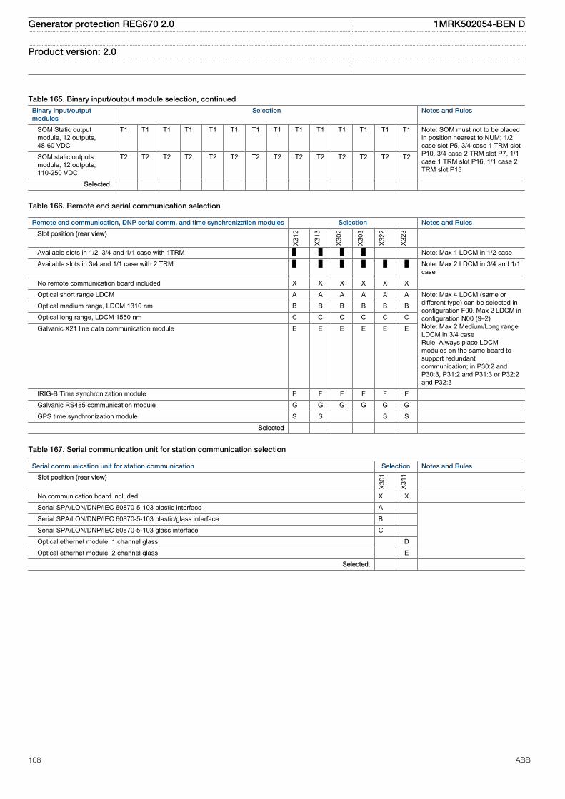
Table 165. Binary input/output module selection, continuedBinary input/outputmodules
Selection Notes and Rules
SOM Static outputmodule, 12 outputs,48-60 VDC
T1 T1 T1 T1 T1 T1 T1 T1 T1 T1 T1 T1 T1 T1 Note: SOM must not to be placedin position nearest to NUM; 1/2case slot P5, 3/4 case 1 TRM slotP10, 3/4 case 2 TRM slot P7, 1/1case 1 TRM slot P16, 1/1 case 2TRM slot P13
SOM static outputsmodule, 12 outputs,110-250 VDC
T2 T2 T2 T2 T2 T2 T2 T2 T2 T2 T2 T2 T2 T2
Selected.
Table 166. Remote end serial communication selection
Remote end communication, DNP serial comm. and time synchronization modules Selection Notes and Rules
Slot position (rear view)
X312
X313
X302
X303
X322
X323
Available slots in 1/2, 3/4 and 1/1 case with 1TRM █ █ █ █ Note: Max 1 LDCM in 1/2 case Available slots in 3/4 and 1/1 case with 2 TRM █ █ █ █ █ █ Note: Max 2 LDCM in 3/4 and 1/1
case No remote communication board included X X X X X X Optical short range LDCM A A A A A A Note: Max 4 LDCM (same or
different type) can be selected inconfiguration F00. Max 2 LDCM inconfiguration N00 (9–2)Note: Max 2 Medium/Long rangeLDCM in 3/4 caseRule: Always place LDCMmodules on the same board tosupport redundantcommunication; in P30:2 andP30:3, P31:2 and P31:3 or P32:2and P32:3
Optical medium range, LDCM 1310 nm B B B B B B Optical long range, LDCM 1550 nm C C C C C C Galvanic X21 line data communication module E E E E E E
IRIG-B Time synchronization module F F F F F F Galvanic RS485 communication module G G G G G G GPS time synchronization module S S S S Selected
Table 167. Serial communication unit for station communication selection
Serial communication unit for station communication Selection Notes and Rules
Slot position (rear view)
X301
X311
No communication board included X X Serial SPA/LON/DNP/IEC 60870-5-103 plastic interface A Serial SPA/LON/DNP/IEC 60870-5-103 plastic/glass interface B Serial SPA/LON/DNP/IEC 60870-5-103 glass interface C Optical ethernet module, 1 channel glass D Optical ethernet module, 2 channel glass E Selected.
Generator protection REG670 2.0 1MRK502054-BEN D
Product version: 2.0
108 ABB
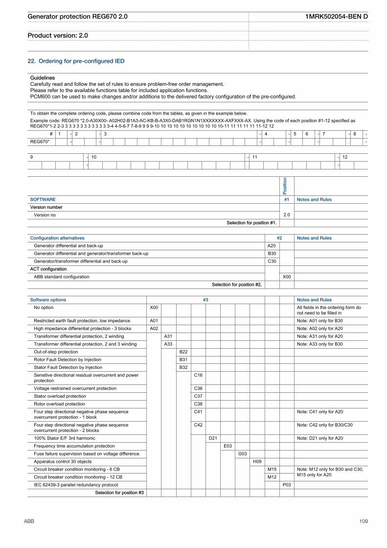
22. Ordering for pre-configured IED
GuidelinesCarefully read and follow the set of rules to ensure problem-free order management.Please refer to the available functions table for included application functions.PCM600 can be used to make changes and/or additions to the delivered factory configuration of the pre-configured.
To obtain the complete ordering code, please combine code from the tables, as given in the example below.Example code: REG670 *2.0-A30X00- A02H02-B1A3-AC-KB-B-A3X0-DAB1RGN1N1XXXXXXX-AXFXXX-AX. Using the code of each position #1-12 specified asREG670*1-2 2-3 3 3 3 3 3 3 3 3 3 3 3 3-4 4-5-6-7 7-8-9 9 9 9-10 10 10 10 10 10 10 10 10 10 10-11 11 11 11 11 11-12 12
# 1 - 2 - 3 - 4 - 5 6 - 7 - 8 -REG670* - - - - - . -
9 - 10 - 11 - 12 - . -
Po
sitio
n
SOFTWARE #1 Notes and Rules
Version number Version no 2.0
Selection for position #1.
Configuration alternatives #2 Notes and Rules
Generator differential and back-up A20 Generator differential and generator/transformer back-up B30 Generator/transformer differential and back-up C30 ACT configuration ABB standard configuration X00 Selection for position #2.
Software options #3 Notes and Rules
No option X00 All fields in the ordering form donot need to be filled in
Restricted earth fault protection, low impedance A01 Note: A01 only for B30 High impedance differential protection - 3 blocks A02 Note: A02 only for A20 Transformer differential protection, 2 winding A31 Note: A31 only for A20 Transformer differential protection, 2 and 3 winding A33 Note: A33 only for B30 Out-of-step protection B22 Rotor Fault Detection by Injection B31 Stator Fault Detection by Injection B32 Sensitive directional residual overcurrent and power
protection C16
Voltage restrained overcurrent protection C36 Stator overload protection C37 Rotor overload protection C38 Four step directional negative phase sequence
overcurrent protection - 1 blockC41 Note: C41 only for A20
Four step directional negative phase sequenceovercurrent protection - 2 blocks
C42 Note: C42 only for B30/C30
100% Stator E/F 3rd harmonic D21 Note: D21 only for A20 Frequency time accumulation protection E03 Fuse failure supervision based on voltage difference G03 Apparatus control 30 objects H09 Circuit breaker condition monitoring - 6 CB M15 Note: M12 only for B30 and C30,
M15 only for A20 Circuit breaker condition monitoring - 12 CB M12 IEC 62439-3 parallel redundancy protocol P03 Selection for position #3
Generator protection REG670 2.0 1MRK502054-BEN D
Product version: 2.0
ABB 109
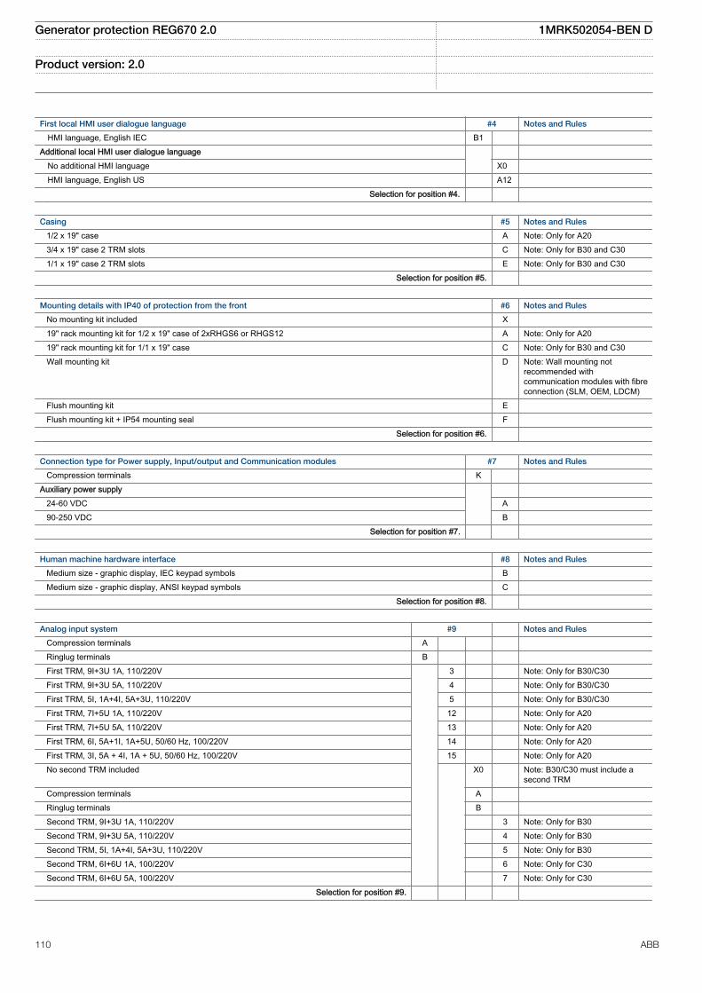
First local HMI user dialogue language #4 Notes and Rules
HMI language, English IEC B1 Additional local HMI user dialogue language No additional HMI language X0 HMI language, English US A12 Selection for position #4.
Casing #5 Notes and Rules
1/2 x 19" case A Note: Only for A20 3/4 x 19" case 2 TRM slots C Note: Only for B30 and C30 1/1 x 19" case 2 TRM slots E Note: Only for B30 and C30 Selection for position #5.
Mounting details with IP40 of protection from the front #6 Notes and Rules
No mounting kit included X 19" rack mounting kit for 1/2 x 19" case of 2xRHGS6 or RHGS12 A Note: Only for A20 19" rack mounting kit for 1/1 x 19" case C Note: Only for B30 and C30 Wall mounting kit D Note: Wall mounting not
recommended withcommunication modules with fibreconnection (SLM, OEM, LDCM)
Flush mounting kit E Flush mounting kit + IP54 mounting seal F Selection for position #6.
Connection type for Power supply, Input/output and Communication modules #7 Notes and Rules
Compression terminals K Auxiliary power supply 24-60 VDC A 90-250 VDC B Selection for position #7.
Human machine hardware interface #8 Notes and Rules
Medium size - graphic display, IEC keypad symbols B Medium size - graphic display, ANSI keypad symbols C Selection for position #8.
Analog input system #9 Notes and Rules
Compression terminals A Ringlug terminals B First TRM, 9I+3U 1A, 110/220V 3 Note: Only for B30/C30 First TRM, 9I+3U 5A, 110/220V 4 Note: Only for B30/C30 First TRM, 5I, 1A+4I, 5A+3U, 110/220V 5 Note: Only for B30/C30 First TRM, 7I+5U 1A, 110/220V 12 Note: Only for A20 First TRM, 7I+5U 5A, 110/220V 13 Note: Only for A20 First TRM, 6I, 5A+1I, 1A+5U, 50/60 Hz, 100/220V 14 Note: Only for A20 First TRM, 3I, 5A + 4I, 1A + 5U, 50/60 Hz, 100/220V 15 Note: Only for A20 No second TRM included X0 Note: B30/C30 must include a
second TRM Compression terminals A Ringlug terminals B Second TRM, 9I+3U 1A, 110/220V 3 Note: Only for B30 Second TRM, 9I+3U 5A, 110/220V 4 Note: Only for B30 Second TRM, 5I, 1A+4I, 5A+3U, 110/220V 5 Note: Only for B30 Second TRM, 6I+6U 1A, 100/220V 6 Note: Only for C30 Second TRM, 6I+6U 5A, 100/220V 7 Note: Only for C30 Selection for position #9.
Generator protection REG670 2.0 1MRK502054-BEN D
Product version: 2.0
110 ABB
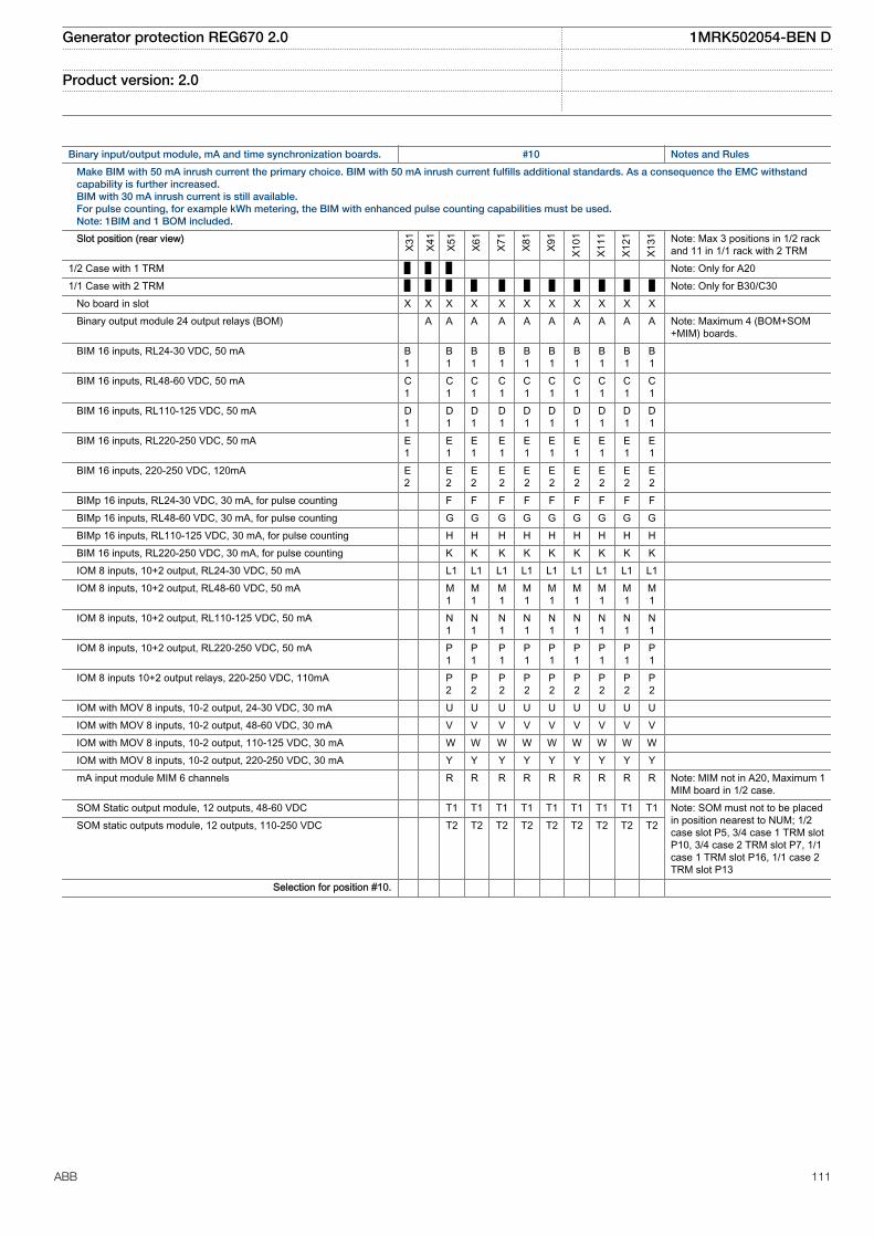
Binary input/output module, mA and time synchronization boards. #10 Notes and Rules
Make BIM with 50 mA inrush current the primary choice. BIM with 50 mA inrush current fulfills additional standards. As a consequence the EMC withstandcapability is further increased.BIM with 30 mA inrush current is still available.For pulse counting, for example kWh metering, the BIM with enhanced pulse counting capabilities must be used.Note: 1BIM and 1 BOM included.
Slot position (rear view)
X31
X41
X51
X61
X71
X81
X91
X101
X111
X121
X131 Note: Max 3 positions in 1/2 rack
and 11 in 1/1 rack with 2 TRM1/2 Case with 1 TRM █ █ █ Note: Only for A201/1 Case with 2 TRM █ █ █ █ █ █ █ █ █ █ █ Note: Only for B30/C30 No board in slot X X X X X X X X X X X Binary output module 24 output relays (BOM) A A A A A A A A A A Note: Maximum 4 (BOM+SOM
+MIM) boards. BIM 16 inputs, RL24-30 VDC, 50 mA B
1 B
1B1
B1
B1
B1
B1
B1
B1
B1
BIM 16 inputs, RL48-60 VDC, 50 mA C1
C1
C1
C1
C1
C1
C1
C1
C1
C1
BIM 16 inputs, RL110-125 VDC, 50 mA D1
D1
D1
D1
D1
D1
D1
D1
D1
D1
BIM 16 inputs, RL220-250 VDC, 50 mA E1
E1
E1
E1
E1
E1
E1
E1
E1
E1
BIM 16 inputs, 220-250 VDC, 120mA E2
E2
E2
E2
E2
E2
E2
E2
E2
E2
BIMp 16 inputs, RL24-30 VDC, 30 mA, for pulse counting F F F F F F F F F BIMp 16 inputs, RL48-60 VDC, 30 mA, for pulse counting G G G G G G G G G BIMp 16 inputs, RL110-125 VDC, 30 mA, for pulse counting H H H H H H H H H BIM 16 inputs, RL220-250 VDC, 30 mA, for pulse counting K K K K K K K K K IOM 8 inputs, 10+2 output, RL24-30 VDC, 50 mA L1 L1 L1 L1 L1 L1 L1 L1 L1 IOM 8 inputs, 10+2 output, RL48-60 VDC, 50 mA M
1M1
M1
M1
M1
M1
M1
M1
M1
IOM 8 inputs, 10+2 output, RL110-125 VDC, 50 mA N1
N1
N1
N1
N1
N1
N1
N1
N1
IOM 8 inputs, 10+2 output, RL220-250 VDC, 50 mA P1
P1
P1
P1
P1
P1
P1
P1
P1
IOM 8 inputs 10+2 output relays, 220-250 VDC, 110mA P2
P2
P2
P2
P2
P2
P2
P2
P2
IOM with MOV 8 inputs, 10-2 output, 24-30 VDC, 30 mA U U U U U U U U U IOM with MOV 8 inputs, 10-2 output, 48-60 VDC, 30 mA V V V V V V V V V IOM with MOV 8 inputs, 10-2 output, 110-125 VDC, 30 mA W W W W W W W W W IOM with MOV 8 inputs, 10-2 output, 220-250 VDC, 30 mA Y Y Y Y Y Y Y Y Y mA input module MIM 6 channels R R R R R R R R R Note: MIM not in A20, Maximum 1
MIM board in 1/2 case. SOM Static output module, 12 outputs, 48-60 VDC T1 T1 T1 T1 T1 T1 T1 T1 T1 Note: SOM must not to be placed
in position nearest to NUM; 1/2case slot P5, 3/4 case 1 TRM slotP10, 3/4 case 2 TRM slot P7, 1/1case 1 TRM slot P16, 1/1 case 2TRM slot P13
SOM static outputs module, 12 outputs, 110-250 VDC T2 T2 T2 T2 T2 T2 T2 T2 T2
Selection for position #10.
Generator protection REG670 2.0 1MRK502054-BEN D
Product version: 2.0
ABB 111

Remote end communication, DNP serial comm. and time synchronization modules #11 Notes and Rules
Slot position (rear view)
X312
X313
X302
X303
X322
X323
Available slots in 1/2 case with 1TRM █ █ █ █ Note: Max 1 LDCM in 1/2 case Available slots in 1/1 case with 2 TRM █ █ █ █ █ █ Note: Max 2 LDCM in 1/1 case No remote communication board included X X X X X X Optical short range LDCM A A A A A A Note: Max 2 LDCM (same or
different type) can be selectedRule: Always place LDCMmodules on the same board tosupport redundantcommunication; in P30:2 andP30:3, P31:2 and P31:3 or P32:2and P32:3
Optical medium range, LDCM 1310 nm B B B B B B
IRIG-B Time synchronization module F F F F F F Galvanic RS485 communication module G G G G G G GPS time synchronization module S S S S Selection for position #11.
Serial communication unit for station communication #12 Notes and Rules
Slot position (rear view)
X301
X311
No communication board included X X Serial and LON communication module (plastic) A Serial (plastic) and LON (glass) communication module B Serial and LON communication module (glass) C Optical ethernet module, 1 channel glass D Optical ethernet module, 2 channel glass E Selection for position #12.
Generator protection REG670 2.0 1MRK502054-BEN D
Product version: 2.0
112 ABB

23. Ordering for Accessories
AccessoriesGPS antenna and mounting details
GPS antenna, including mounting kits Quantity: 1MRK 001 640-AA
Cable for antenna, 20 m Quantity: 1MRK 001 665-AA
Cable for antenna, 40 m Quantity: 1MRK 001 665-BA
Interface converter (for remote end data communication)
External interface converter from C37.94 to G703 Quantity: 1 2 1MRK 002 245-AA
External interface converter from C37.94 to G703.E1 Quantity: 1 2 1MRK 002 245-BA
Test switchThe test system COMBITEST intended for use with the IED 670products is described in 1MRK 512 001-BEN and 1MRK001024-CA. Please refer to the website:www.abb.com/substationautomation for detailed information.
Due to the high flexibility of our product and the wide variety ofapplications possible the test switches needs to be selected foreach specific application.
Select your suitable test switch based on the available contactsarrangements shown in the reference documentation.
However our proposals for suitable variants are:
Two winding transformer with internal neutral on currentcircuits. Two pcs can be used in applications for three windingtransformers in single or multi-breaker arrangement (orderingnumber RK926 315-BD)
Two winding transformer with external neutral on currentcircuits. Two pcs can be used in applications for three winding
transformers in single or multi-breaker arrangement (orderingnumber RK926 315-BH).
Three winding transformer with internal neutral on currentcircuits (ordering number RK926 315-BX).
The normally open "In test mode" contact 29-30 on the RTXPtest switches should be connected to the input of the testfunction block to allow activation of functions individually duringtesting.
Test switches type RTXP 24 is ordered separately. Please referto Section Related documents for references to correspondingdocuments.
RHGS 6 Case or RHGS 12 Case with mounted RTXP 24 and theon/off switch for dc-supply are ordered separately. Please referto Section Related documents for references to correspondingdocuments.
Protection cover
Protective cover for rear side of RHGS6, 6U, 1/4 x 19” Quantity: 1MRK 002 420-AE
Protective cover for rear side of terminal, 6U, 1/2 x 19” Quantity: 1MRK 002 420-AC
Protective cover for rear side of terminal, 6U, 3/4 x 19” Quantity: 1MRK 002 420-AB
Protective cover for rear side of terminal, 6U, 1/1 x 19” Quantity: 1MRK 002 420-AA
Generator protection REG670 2.0 1MRK502054-BEN D
Product version: 2.0
ABB 113

External resistor unit
High impedance resistor unit 1-ph with resistor and voltage dependent resistor for 20-100Voperating voltage
Quantity:
1 2 3 RK 795 101-MA
High impedance resistor unit 3-ph with resistor and voltage dependent resistor for 20-100Voperating voltage
Quantity: RK 795 101-MB
High impedance resistor unit 1-ph with resistor and voltage dependent resistor for 100-400Voperating voltage
Quantity:
1 2 3 RK 795 101-CB
High impedance resistor unit 3-ph with resistor and voltage dependent resistor for 100-400Voperating voltage
Quantity: RK 795 101-DC
Generator protection REG670 2.0 1MRK502054-BEN D
Product version: 2.0
114 ABB

Injection equipment
Rule: If injection equipment is ordered, ROTIPHIZ or STTIPHIZSensitive rotor earth fault protection, injection based(option B31) or 100% stator earth fault protection, injection based (option B32) is required in the IED.
Injection unit, REX060 Quantity: 1MRK 002 500-AA
Casing
1/2 x 19" rack casing Basic
Backplane module (BPM) Basic
Human machine interface
HMI and logic module (HLM) Basic
Injection modulesNote: One of RIM and SIM have to be selected if REX060 is specified
Rule: Stator injection module (SIM) is required if 100% stator earth fault protection, injectionbased (option B32)(STTIPHIZ) is selected/active in REG670
Stator injection module (SIM) 1MRK 002 544-AA
Rule: Rotor injection module (RIM) is required if Sensitive rotor earth fault protection, injectionbased (option B31) (ROTIPHIZ) is selected/active in REG670
Rotor injection module (RIM) 1MRK 002 544-BA
Power supply module
Rule: One Power supply module must be specified
Power supply module (PSM) 24-60 VDC 1MRK 002 239-AB
90-250 VDC 1MRK 002 239-BB
Mounting details with IP40 of protection from the front
19" rack mounting kit 1MRK 002 420-BB
Wall mounting kit for terminal 1MRK 002 420-DA
Flush mounting kit for terminal 1MRK 000 020-Y
Extra IP54 mounting seal + Flush mounting kit for terminal 1MRK 002 420-EA
Rule: REX061 requires REX060 and that Rotor injection module (RIM) is selected in REX060 andthat Sensitive rotor earth fault protection, injection based (option B31)(ROTIPHIZ) is selected/active in REG670.
Coupling capacitor unit, REX061 Quantity: 1MRK 002 550-AA
Rule: REX062 requires REX060 and that Stator injection module (SIM) is selected in REX060 andthat 100% stator earth fault protection, injection based (option B32)(STTIPHIZ) is selected/activein REG670.
Shunt resistor unit, REX062 Quantity: 1MRK 002 555-AA
Combiflex
Key switch for settings
Key switch for lock-out of settings via LCD-HMI Quantity: 1MRK 000 611-A
Note: To connect the key switch, leads with 10 A Combiflex socket on one end must be used.
Generator protection REG670 2.0 1MRK502054-BEN D
Product version: 2.0
ABB 115

Mounting kit Ordering number
Side-by-side mounting kit Quantity: 1MRK 002 420-Z
Injection unit for Rotor earth fault protection (RXTTE 4)Note: Requires additional COMBIFLEX terminal base RX4, 10A COMBIFLEX sockets and appropriateCOMBIFLEX mounting accessories for proper operation
Quantity: 1MRK 002 108-BA
Protective resistor on plate Quantity: RK795102-AD
Configuration and monitoring tools
Front connection cable between LCD-HMI and PC Quantity: 1MRK 001 665-CA
LED Label special paper A4, 1 pc Quantity: 1MRK 002 038-CA
LED Label special paper Letter, 1 pc Quantity: 1MRK 002 038-DA
Manuals
Note: One (1) IED Connect CD containing user documentation (Operation manual, Technical manual,Installation manual, Commissioning manual, Application manual and Getting started guide), Connectivitypackages and LED label template is always included for each IED.
Rule: Specify additional quantity of IED Connect CD requested. Quantity: 1MRK 002 290-AD
Generator protection REG670 2.0 1MRK502054-BEN D
Product version: 2.0
116 ABB

User documentation
Rule: Specify the number of printed manuals requested
Application manual IEC Quantity: 1MRK 502 051-UEN
ANSI Quantity: 1MRK 502 051-UUS
Technical manual IEC Quantity: 1MRK 502 052-UEN
ANSI Quantity: 1MRK 502 052-UUS
Commissioning manual IEC Quantity: 1MRK 502 053-UEN
ANSI Quantity: 1MRK 502 053-UUS
Communication protocol manual, IEC 61850 Edition 1, 670 series IEC Quantity: 1MRK 511 302-UEN
Communication protocol manual, IEC 61850 Edition 2, 670 series IEC Quantity: 1MRK 511 303-UEN
Communication protocol manual, IEC 60870-5-103, 670 series IEC Quantity: 1MRK 511 304-UEN
Communication protocol manual, LON, 670 series IEC Quantity: 1MRK 511 305-UEN
Communication protocol manual, SPA, 670 series IEC Quantity: 1MRK 511 306-UEN
Communication protocol manual, DNP,670 series
ANSI Quantity: 1MRK 511 301-UUS
Point list manual, DNP 670 series ANSI Quantity 1MRK 511 307-UUS
Operation manual, 670 series IEC Quantity: 1MRK 500 118-UEN
ANSI Quantity: 1MRK 500 118-UUS
Installation manual, 670 series IEC Quantity: 1MRK 514 019-UEN
ANSI Quantity: 1MRK 514 019-UUS
Generator protection REG670 2.0 1MRK502054-BEN D
Product version: 2.0
ABB 117

Engineering manual, 670 series IEC Quantity: 1MRK 511 308-UEN
ANSI Quantity: 1MRK 511 308-UUS
Cyber security guideline IEC Quantity: 1MRK 511 309-UEN
Reference information
For our reference and statistics we would be pleased to be provided with the following application data:
Country: End user:
Station name: Voltage level: kV
Generator manufacturer: Rated power: MVA
Type of prime mover: steam , gas , hydro , pumpstorage , nuclear , other ______________________
Related documents
Documents related to REG670 Identify number
Application manual 1MRK 502 051-UEN
Commissioning manual 1MRK 502 053-UEN
Product guide 1MRK 502 054-BEN
Technical manual 1MRK 502 052-UEN
Type test certificate 1MRK 502 054-TEN
670 series manuals Identify number
Operation manual 1MRK 500 118-UEN
Engineering manual 1MRK 511 308-UEN
Installation manual 1MRK 514 019-UEN
Communication protocol manual,IEC 60870-5-103
1MRK 511 304-UEN
Communication protocol manual,IEC 61850 Edition 1
1MRK 511 302-UEN
Communication protocol manual,IEC 61850 Edition 2
1MRK 511 303-UEN
Communication protocol manual,LON
1MRK 511 305-UEN
Communication protocol manual,SPA
1MRK 511 306-UEN
Accessories guide 1MRK 514 012-BEN
Cyber security deploymentguideline
1MRK 511 309-UEN
Connection and Installationcomponents
1MRK 513 003-BEN
Test system, COMBITEST 1MRK 512 001-BEN
Generator protection REG670 2.0 1MRK502054-BEN D
Product version: 2.0
118 ABB

119
Contact us
For more information please contact:
ABB ABSubstation Automation ProductsSE-721 59 Västerås, SwedenPhone +46 (0) 21 32 50 00
www.abb.com/substationautomation
Note:We reserve the right to make technical changes or modify thecontents of this document without prior notice. ABB AB doesnot accept any responsibility whatsoever for potential errorsor possible lack of information in this document.We reserve all rights in this document and in the subjectmatter and illustrations contained herein. Any reproduction,disclosure to third parties or utilization of its contents – inwhole or in part – is forbidden without prior written consent ofABB AB.
© Copyright 2014 ABB.
All rights reserved.
Scan this QR code to visit our website
1MR
K50
2054
-BE
N