Embed Size (px)
Citation preview

Catalog HB1 and VB1 ⋅ Edition 2017
HB1 and VB1 Generator Circuit-Breaker SwitchgearMedium-Voltage Switchgear
siemens.com/generatorswitchgear

R-H
B1VB
1-00
3.tif
R-H
B1-0
01.ti
f
R-H
B1VB
1-00
1.tif
R-H
B1VB
1-00
2.tif
R-H
B1-0
03.ti
f
R-H
B1-0
02.ti
f
2 HB1 and VB1 Generator Circuit-Breaker Switchgear · Siemens HB1 and VB1 · 2017
Application:• Gas-fired, gas-turbine-driven power plants• Coal- and oil-fired steam turbine-driven power plants• Concentrated solar steam turbine-driven power plants• Hydro turbine-driven power plants• Geothermal power plants• Main distribution switchgear for heavy duty application
ApplicationTypical uses

3HB1 and VB1 Generator Circuit-Breaker Switchgear · Siemens HB1 and VB1 · 2017
HB1 and VB1 Generator Circuit-Breaker SwitchgearMedium-Voltage Switchgear
Catalog HB1 and VB1 · 2017
Invalid: Catalog HB1 and VB1 · 2014
siemens.com/generatorswitchgear
The products and systems described in this catalog are manufactured and sold according to a certified management system (acc. to ISO 9001, ISO 14001 and BS OHSAS 18001).
Application SeiteTypes 4Overview 5Typical uses, classification 6
RequirementsCustomer benefits, design features 7 and 8
Technical dataHB1 electrical data, dimensions 9VB1 electrical data, dimensions 10Room planning 11Connection 12Connection types, transport 13
DesignEnclosure 14Interlocks 15Operation, control panel, features 16
Product rangeHB1 switchgear 17VB1 switchgear 18 and 19
ComponentsVacuum circuit-breaker 20Generator vacuum circuit-breaker 21Disconnectors, fused load break switches and earthing switches 22Surge arresters, capacitors, current and voltage transformers, fuses 23
StandardsStandards, specifications, guidelines 24 to 27
Contents
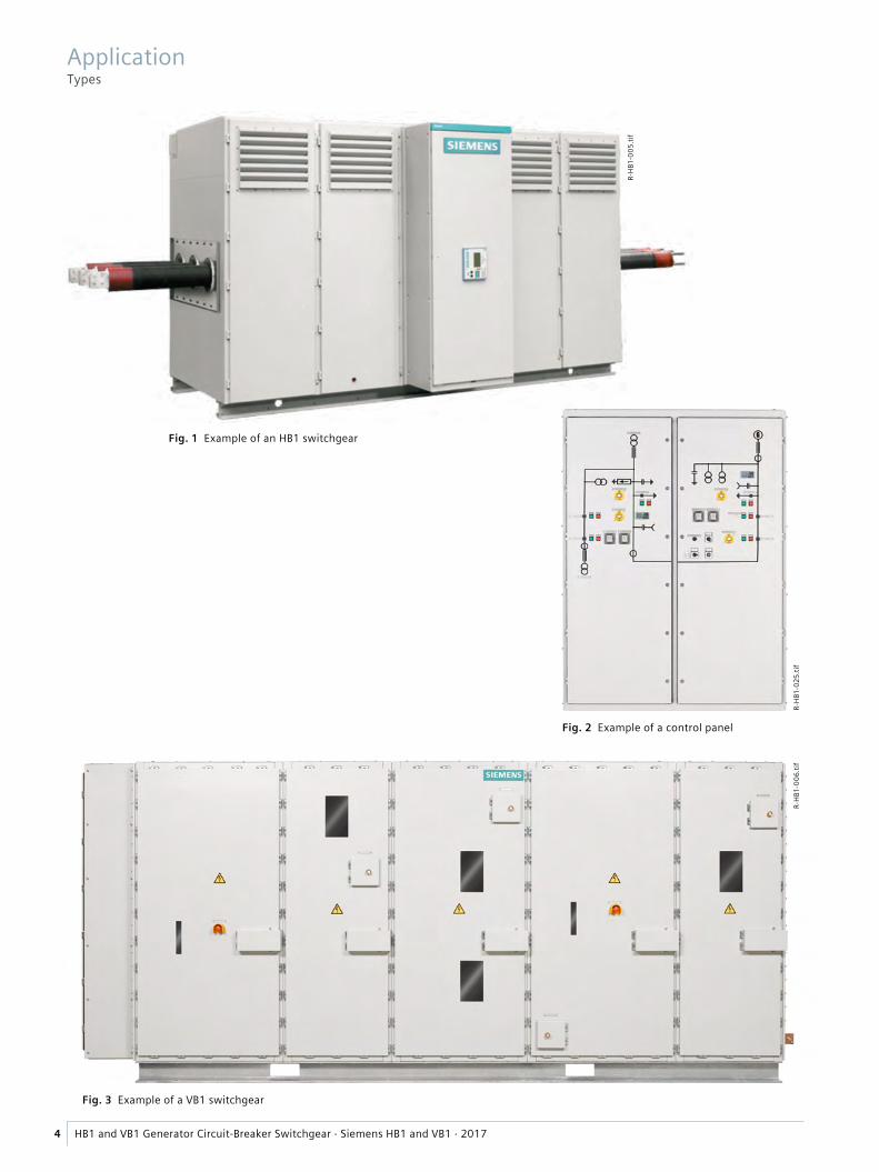
Fig. 1 Example of an HB1 switchgear
Fig. 3 Example of a VB1 switchgear
R-H
B1-0
05.ti
f
Fig. 2 Example of a control panel
R-H
B1-0
25.ti
fR-
HB1
-006
.tif
4 HB1 and VB1 Generator Circuit-Breaker Switchgear · Siemens HB1 and VB1 · 2017
ApplicationTypes
HB1-0001_en eps
Near-to-generator short-circuit, delayed current zero
Near-to-generator short-circuit
Far-from-generator short-circuit in the distribution network
Isc
t
Isc
t
Isc
t
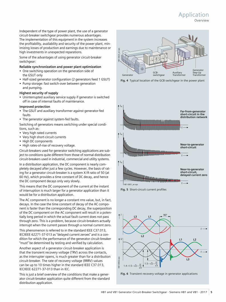
Fig. 4 Typical location of the GCB switchgear in the power plant
Fig. 5 Short-circuit current profiles
Fig. 6 Transient recovery voltage in generator applications
HB1
-000
2a e
ps
L1 L2
L3
L2
L3 L190°
U
I
1.5 • √2 •√3U
1.4 •1.5 • √2 •√3U
t
t
HB1
-002
3_en
eps
GeneratorGCB-switchgear
AuxiliaryTransformer
GeneratorStep-UpTransformer
5HB1 and VB1 Generator Circuit-Breaker Switchgear · Siemens HB1 and VB1 · 2017
Independent of the type of power plant, the use of a generator circuit-breaker switchgear provides numerous advantages.The implementation of this equipment in the system increases the profitability, availability and security of the power plant, min-imizing losses of production and earnings due to maintenance or high investments in unexpected reparations. Some of the advantages of using generator circuit-breaker switchgear:Reliable synchronization and power plant optimization • One switching operation on the generation side of
the GSUT only• Half-sized generator configuration (2 generators feed 1 GSUT)• Pump storage: fast switch-over between generation
and pumping.Highest security of supply• Uninterrupted auxiliary service supply if generator is switched
off in case of internal faults of maintenance.Improved protection• The GSUT and auxiliary transformer against generator-fed
faults• The generator against system-fed faults.Switching of generators means switching under special condi-tions, such as:• Very high rated currents • Very high short-circuit currents• High DC components• High rates-of-rise of recovery voltage.Circuit-breakers used for generator switching applications are sub-ject to conditions quite different from those of normal distribution circuit-breakers used in industrial, commercial and utility systems.In a distribution application, the DC component is nearly com-pletely decayed after just a few cycles. However, the basis of rat-ing for a generator circuit-breaker is a system X / R ratio of 50 (at 60 Hz), which provides a time constant of DC decay, and hence the DC component decays only very slowly. This means that the DC component of the current at the instant of interruption is much larger for a generator application than it would be for a distribution application.The AC component is no longer a constant rms value, but, in fact, decays. In the case the time constant of decay of the AC compo-nent is faster than the corresponding DC decay, the superposition of the DC component on the AC component will result in a poten-tially long period in which the actual fault current does not pass through zero. This is a problem, because circuit-breakers actually interrupt when the current passes through a normal current zero. This phenomenon is referred to in the standard IEEE C37.013, IEC/IEEE 62271-37-013 as “delayed current zeroes” and is a con-dition for which the performance of the generator circuit-breaker “must” be determined by testing and verified by calculation.Another aspect of a generator circuit-breaker application is that the transient recovery voltage (TRV) across the contacts, as the interrupter opens, is much greater than for a distribution circuit-breaker. The rate of recovery voltage (RRRV) values can be up to 10 times higher in the standard IEEE C37.013, IEC/IEEE 62271-37-013 than in IEC. This is just a brief overview of the conditions that make a gener-ator circuit-breaker application quite different from the standard distribution application.
ApplicationOverview

Fig. 7 Portfolio
R-HB
1VB1
-010
_en
eps
6 HB1 and VB1 Generator Circuit-Breaker Switchgear · Siemens HB1 and VB1 · 2017
Siemens generator circuit-breaker switchgear types HB1 and VB1 are factory-assembled, air-insulated, metal-enclosed, non-phase segregated switchgear for indoor and outdoor installation and they are designed according to the standards IEC 61271-1 and IEC 61936-1 (VDE 0101). The type tests of the HB1 and VB1 have been carried out according to the standard IEC 62271-200.
Siemens is one of the leading manufacturers in the field of vacuum circuit-breaker and switchgear technology, provid-ing solutions to the most demanding clients all over the world.
The HB1 and VB1 circuit-breaker switchgear provide a com-pact solution which can be customized to the individual needs of our clients. The application of the HB1 and VB1 switchgear is done both in power plants and as high-cur-rent-/furnace switchgear.
For current interruption capabilities, Siemens vacuum generator circuit-breaker types 3AH37 and 3AH38 are used, which are type tested and compliant with the generator circuit-breaker standard IEEE C37.013, IEEE/IEC 62271-37-013.
For severe ambient conditions, like e.g. in deserts or very corrosive atmospheres with chemical content in the air, the HB1 and VB1 switchgear can be installed in container modules equipped with its own auxiliary devices and be delivered to the site completely tested.
Direct connection to the generator terminals is also pos-sible due to the modular design of the HB1, providing cost savings and avoiding additional connection from the gen-erator to the generator circuit-breaker switchgear.
The HB1 and VB1 generator circuit-breaker switchgear is designed for generators up to 240 MVA for connection between the generator(s) and the step-up transformer(s) and, if applicable, also for auxiliary supply transformers and excitation transformers. They can be used, for exam-ple, in:• Gas-fired, gas-turbine-driven power plants (simple cycle
and combined cycle)• Coal- and oil-fired steam turbine-driven power plants• Concentrated solar steam turbine-driven power plants• Hydro turbine-driven power plants• Geothermal power plants• Main distribution switchgear for heavy duty application
up to 24 kV, 5.000 A, ≥ 50 kA.
The generator circuit-breaker switchgear types HB1 and VB1 correspond to the following classifications:
HB1 VB1Loss of service continuity category and partition classLoss of service continuity category
LSC 1 LSC 1 LSC 2A on request
Partition class None None PI on request PM on request
Internal arc classificationsInternal arc classifications
A FLR 72 kA / 0.1 sA FLR 63 kA / 0.1 sA FLR 63 kA / 1 s
A FL 50 kA / 0.5 sA FL 72 kA / 0.1 s
A = 300 mm distance of indicators for test (installation in closed electrical service location)
F = Front arrangement of indicators for test
L = Lateral arrangement of indicators for test
R = Rear arrangement of indicators for testIsc = Test current 50 kA, 63 kA, 72 kAt = Arc duration 0.1 s, 0.5 s, 1 s
LSC 1 LSC 2ADefinition: Entire shut-down required for access to any compartment of the siwtchgear (busbar, circuit-breaker, earthing switch, disconnector in one common compartment)
Definition: Access to aux.-feeder or connection compart-ment permitted due to discon-nection from grid in segregated compartment
HB1-0003_en eps
Busbar/circuit-breaker/connectioncompartment
Disconnector/earthing switch
HB1-0004_en eps
Circuit-breaker compartment
Busbar compartmentDisconnector/earthing switch
Connection compartment
ApplicationTypical uses, classification

7HB1 and VB1 Generator Circuit-Breaker Switchgear · Siemens HB1 and VB1 · 2017
RequirementsCustomer benefits, design features
Based on years of experience and customer orienta-tion as a pioneer in development of vacuum switch-gear technology for reliable transmission and distribu-tion of electrical power in medium voltage, Siemens has gained the competence and solutions for the unique switching duties of generator circuits.
Siemens has optimized its portfolio of high-current and generator circuit-breaker switchgear in order to meet the high demands of the merging market for power generation sets up to 450 MVA.
Customer benefits Design features
• Peace of mind • No handling of insulating gas and therefore no low and high-pressure monitoring required• As insulating medium, air is always available• Use of standard components available worldwide• More than 450,000 air-insulated switchgear panels and systems with vacuum switching technology
operating worldwide• Use of maintenance-free vacuum circuit-breakers• Quality assurance in accordance with DIN EN ISO 9001• Computer-aided calculation and simulation of short-time withstand current and peak current in accordance with
IEC 60909• Dimensioning of enclosure and current path to withstand dynamic and thermal impact of continuous and
short-circuit currents• Verification of breaker interruption capabilities under consideration of delayed current zero• High reliability of vacuum circuit-breakers due to the low number of moving parts inside the arcing chamber• Extremely high mean-time-to-failure (MTTF) values of the vacuum interrupters• No leakage due to the welded connections of the vacuum interrupter.
This sealed for live technology does not require any gas monitoring.
• Optimum safety • Design and construction according to IEC 62271-1 and IEC 61936-1, type tests according to IEC 62271-200• Internal arc classification (IAC) is available for switchgear enclosures• All switching devices can be operated locally by means of electrical commands with all doors and covers closed• In case of loss of electrical control power, the switchgear can be operated manually by means of
emergency operating crank handles or levers, also with all doors and covers closed• The positions of the switching devices are visible through inspection windows• No explosion in the unlikely event of a fault in the vacuum interrupter of the generator circuit-breaker• Switching devices are electrically interlocked• In the extremely unlikely case of a loss of vacuum in the circuit-breaker, only an arc develops, as the
current is interrupted inside a ceramic-metal housing
• Increases productivity
• Loss of service continuity category LSC 2A on request• Partition class PI and PM on request• Maximum degree of protection IP55 possible• Use of maintenance-free vacuum circuit-breakers for 10,000 operating cycles at rated current• Frequent-operation circuit-breakers for up to 120,000 operating cycles available• High reliability of vacuum circuit-breakers due to the low number of moving parts inside the arcing chamber• Extremely high mean-time-to-failure (MTTF) values of the vacuum interrupters
R-H
B1-0
08.ti
f

8 HB1 and VB1 Generator Circuit-Breaker Switchgear · Siemens HB1 and VB1 · 2017
Customer benefits Design features
• Saves money • Use of maintenance-free vacuum circuit-breakers• Due to its compact design the necessary space for installation is minimized thanks to a modular enclosure concept• Factory-assembled, thus reducing installation works on site• Significant lower life-cycle costs in terms of inspection intervals and maintenance costs compared to other
switching medium technologies
• Preserves the environment
• Long lifetime of the switchgear and all components (more than 20 years)• Vacuum switching technology, no gas filling every few years• The materials used are fully recyclable without special knowledge• Easy disposal, no toxic decomposition of products by the arc quenching medium
• Experience With over 40 years of experience in vacuum switching technology, Siemens has perfected its vacuum circuit-break-ers for generator switching applications in particular, where they are subjected to high thermal and mechanical stress.
• Vacuum circuit-breaker
• Special contact material for minimum contact wear and low chopping currents• Specifically developed contact system• Optimized design for efficient cooling• Post insulator construction for highest mechanical stability• Safe breaking operations by controlling long arcing times even in case of delayed zero crossings• Transient recovery voltages with high rates-of-rise, typical for generators, are controlled without additional capaci-
tor circuits.
RequirementsCustomer benefits, design features

���
����
����
�
������
�����������
����
���
���
����
����
�
������
����
���
�������
Fig. 8 Front view Fig. 9 Side view
Example:
9HB1 and VB1 Generator Circuit-Breaker Switchgear · Siemens HB1 and VB1 · 2017
Rated values for HB1Ratedvoltage kV 12 17.5 24frequency Hz 50 / 60 50 / 60 50 / 60short-duration power-frequency withstand voltage kV 28 38 60lightning Impulse withstand voltage kV 75 95 125short-time withstand current kA / s 50 / 3
63 / 172 / 1
50 / 363 / 172 / 1
50 / 363 / 172 / 1
peak withstand current kA 125 / 130 1)
160 / 164 1)
180 / 188 1)
200 2)
125 / 130 1)
160 / 164 1)
180 / 188 1)
200 2)
125 / 130 1)
160 / 164 1)
180 / 188 1)
200 2)
normal current of feeders: IP4X 3) IP54 4) IP4X 3) IP54 4) IP4X 3) IP54 4)
Generator feeder 3150 A VGCB A 2900 2300 2900 2300 2900 2300 Generator feeder 4000 A VGCB A 4200 3300 4200 3300 4200 3300 Generator feeder 5000 A VGCB A 5200 3700 5200 3700 5200 3700 Generator feeder 6300 A VGCB A 6700 4700 6700 4700 6700 4700 Auxiliary transformer feeder 6) for transformers ≤ 1250 kVA A
with FLBS 5)< 125 < 125 < 125
Auxiliary transformer feeder 6) for transformers > 1250 kVA A with 1250 A VCB or 3150 A VGCB
< 1250 < 1250 < 1250
Auxiliary transformer feeder 6) with disconnector A < 1250 < 1250 < 1250 Auxiliary transformer feeder 6) without switching devices A < 1250 < 1250 < 1250 Auxiliary transformer feeder 6) with fuse link A < 200 < 200 < 200
1) Values for 60 Hz 2) Values on request 3) Also with IP41, IP42 4) Also with IP55 for outdoor use 5) Fused load break switch 6) Optional feature, available on request
X is defined depending on the type of connection
Technical dataHB1 electrical data, dimensions

���
����
����
�
�
����
���
����
���
����
����
�
�������������
����
���
Fig. 10 Front view VB1
Fig. 11 Top view VB1
Example:
10 HB1 and VB1 Generator Circuit-Breaker Switchgear · Siemens HB1 and VB1 · 2017
Rated values for VB1Ratedvoltage kV 12 17.5 24frequency Hz 50 / 60 50 / 60 50 / 60short-duration power-frequency withstand voltage kV 28 38 60lightning Impulse withstand voltage kV 75 95 125short-time withstand current kA / s 50 / 3
63 / 172 / 1
50 / 363 / 172 / 1
50 / 363 / 172 / 1
peak withstand current kA 125 / 130 1)
160 / 164 1)
180 / 188 1)
200 2)
125 / 130 1)
160 / 164 1)
180 / 188 1)
200 2)
125 / 130 1)
160 / 164 1)
180 / 188 1)
200 2)
normal current of feeders: IP4X 3) IP54 4) IP4X 3) IP54 4) IP4X 3) IP54 4)
Generator/Transformer feeder 3150 A VGCB A 2830 2680 2830 2680 2680 2680 Generator/Transformer feeder 4000 A VGCB A 4200 3000 4200 3000 4200 3000 Generator/Transformer feeder 5000 A VGCB A 4400 3150 4400 3150 4400 3150 Generator/Transformer feeder 6300 A VGCB A 5800 4000 5800 4000 5800 4000 Auxiliary transformer feeder for transformers ≤ 1250 kVA A
with FLBS 5)< 125 < 125 < 125
Auxiliary transformer feeder for transformers > 1250 kVA A with 1250 A VCB or 3150 A VGCB
< 1250 < 1250 < 1250
Auxiliary transformer feeder with disconnector A < 1250 < 1250 < 1250 Auxiliary transformer feeder without switching devices A < 1250 < 1250 < 1250 Auxiliary transformer feeder with fuse link A < 200 < 200 < 200
1) Values for 60 Hz 2) Values on request
3) Also with IP41, IP42 4) Also with IP55 for outdoor use
Technical dataVB1 electrical data, dimensions
5) Fused load break switch
X = Panel width from 600 mm to 1300 mm, Y = is defined depending on the panel functionality

���
����
����
�
���
����
���
��
����
����
��
�����������������������
��������� �����
���
����
������
���������
���
����
����
�
���������
Installation
Fig. 12 Top view HB1
Fig. 13 Front view HB1
Fig. 14 Front view VB1
Fig. 15 Example of pressure relief duct
���
����
����
�
11HB1 and VB1 Generator Circuit-Breaker Switchgear · Siemens HB1 and VB1 · 2017
Plan view
Room planning for HB1 and VB1
Recommended minimum distances for maintenance
In case of a room height of above 4000 mm, pressure relief is adequate from the top. Otherwise, the pressure relief system must be evaluated according to the room conditions.
In case of a room height of above 4000 mm, pressure relief is adequate from the top. Otherwise, the pressure relief system must be evalu-ated according to the room conditions.
Technical dataRoom planning

Fig. 16 Possibilities for connection of an HB1 switchgear
or
and/or
or
and/or
or
and/or
or
and/or
or
or or
*)
HB1
-001
2_en
eps
or
or
and/or
or
HB1
-001
3_en
eps
12 HB1 and VB1 Generator Circuit-Breaker Switchgear · Siemens HB1 and VB1 · 2017
The connection to the generator and the transformer can be done by means of either cables, fully-insulated busbars or non-phase segregated bus ducts. The connection to the terminals can be either from top, bottom or horizontally from the left and right side.
Similar connection types are available for VB1 switchgear. The location is to be defined according to the project requirements.
*) Only without auxiliary feeder
Connection with cables
Connection with busbar system
Technical dataConnection

R-H
B1-0
09.ti
fR-
HB1
-010
.tif
R-H
B1-0
12.ti
f
R-H
B1-0
11.p
sd
Fig. 17 Cable connection from bottom
Fig. 18 Fully-insulated busbars – horizontal connection
Fig. 19 Bus duct connection from top
Fig. 20 Fully-insulated busbars – bottom connection
13HB1 and VB1 Generator Circuit-Breaker Switchgear · Siemens HB1 and VB1 · 2017
Connection typesThe connection to the generator and transformer can be done by means of either cables, fully-insulated busbars (e.g. make Moser Glaser, Preissinger, Ritz) or non-phase segre-gated bus ducts. The connection to the terminals can be either from top, bottom or horizontally from the left and right side. Additionally, an isolated phase bus duct with a phase-centre distance < 510 mm can be connected from the side.The access to the connection terminals is covered with non-magnetic sheet metal which is cut out according to the num-ber of cables and respectively the diameter of busbars. Cable glands or flanges are not included in the scope of supply.Connection of the HB1 to the IPB system: Connection to an isolated phase bus duct system (IPB) is available as an option. However, conditions for segregation of the switchgear from pressurized IPB enclosures, earthing systems and details of the flange connection, phase-centre distance, etc. have to be evaluated individually.TransportThe HB1 switchgear is delivered in one factory-assembled transport unit. The VB1 switchgear can be delivered either in one factory-assembled transport unit or in form of sections/individual panels. Please observe the following:• Transport facilities on site• Transport dimensions and transport weights• Size of door openings in building.PackingMeans of transport: Truck
– Open packing with PE protective foil.Means of transport: Ship
– In closed crates with sealed upper and lower PE protective foil
– With desiccant bags – With sealed wooden base – Max. storage time: 12 months.
Transport dimensions, transport weight Unit dimension Transport dimensions Transport weight
Width Height Depth with packing
without packing
mm mm mm mm approx. kg approx. kgTransport of HB1 with truck4000 × 2320 × 2300 4000 2700 2400 5750 5500up to 6000 × 2500 × 2300
up to 6000
2700 2400 8000 7750
Transport of HB1 with ship4000 × 2320 × 2300 4500 3000 2800 6750 5500up to 6000 × 2500 × 2300
up to 6000
3000 2800 9250 7750
Transport of VB1 with truck4500 × 2320 x up to 1800
4500 2700 up to 1800
6750 6500
up to 6500 × 2500 × up to 1800
up to 6500
2700 up to 1800
9500 9000
Transport of VB1 with ship4500 × 2320 x up to 1800
5000 3000 2200 7750 6500
up to 6500 × 2500 × up to 1800
up to 7000
3000 2200 10500 9000
Technical dataConnection types, transport

R-H
B1-0
13.ti
f
Fig. 21 Interior view of the VB1 generator circuit-breaker switchgear
1 Generator circuit-breaker
2 Disconnector3 Earthing switch4 Current transformer5 Voltage transformer6 Surge capacitor7 Surge arrester
5 34134
61 627
14 HB1 and VB1 Generator Circuit-Breaker Switchgear · Siemens HB1 and VB1 · 2017
Enclosure for HB1 and VB1
The modular designed switchgear comprises a welded framework construction and bolted sheet-metal enclosure walls.
The doors at the operating side are bolted with hinges. Inspection windows and access holes for the emergency operating tools are provided for all switching devices to allow visual inspection of the switching position and manual operation with all covers closed.
Pressure relief is provided as standard on the roof to release gases in case of internal faults. These can also be provided at the rear side depending on the on-site condi-tions.
The enclosure is available with degrees of protection IP20, IP21, IP40, IP41, IP42 and IP54 for indoor installation.
The degrees of protection IP54 and IP55 with a roof are available for outdoor installation.
The standard enclosure including all internal surfaces is epoxy powder-coated with color RAL 7035. Other RAL col-ors are also available on request. Internal structure parts can be manufactured using stainless steel, aluminium and sensimized steel without further surface coating.
Switchgear enclosure of the main current path (generator feeder)
The switchgear is an air-insulated, three-phase system in one common enclosure (non-phase segregation) with all components necessary for the main current path between generator and main transformer.
A phase-centre distance of up to 470 mm (up to 345 mm for earthing circuits) provides sufficient clearance for safe
isolation between the live parts and live parts to earth under all operating conditions. This large clearance helps to reduce the usage of insulation material to a minimum.
All switching devices are fixed-mounted and the inter-connections are done by flat busbars made of electrolytic copper with standard dimensions of 100 × 10 mm up to 200 × 10 mm.
Switchgear enclosure of the auxiliary current path (auxiliary feeder)
In the case that auxiliary and / or excitation transformer feeders shall be incorporated in the switchgear, additional auxiliary panels can be added.
These feeders are also air-insulated, three-phase systems which are mounted to the longitudinal sides of the enclo-sure construction site.
The main enclosure and auxiliary panels can be separated by metal partitions. Connection to the main current path is done by pre-fabricated busbars.
A phase-centre distance of up to 345 mm provides suf-ficient clearance for safe isolation between the live parts and live parts to earth under all operating conditions.
All switching devices are fixed-mounted and the inter-connections are done by flat busbars made of electrolytic copper with standard dimensions of 100 × 10 mm up to 120 × 10 mm.
DesignEnclosure

15HB1 and VB1 Generator Circuit-Breaker Switchgear · Siemens HB1 and VB1 · 2017
Interlocks
All switching devices are equipped with a motor operating mechanism which is incorporated in the electrical interlock scheme.
In case of emergency (e.g. loss of auxiliary power), the switching devices can be operated manually. However, there are no interlocks in case of manual operation. The access to the manual operation of the switching devices may be protected by means of padlocks.
Minimum standard interlocking conditions for the generator feederGenerator circuit-breaker CLOSE: Associated disconnector in CLOSED position and associ-
ated earthing switches on both sides in OPEN positionGenerator circuit-breaker OPEN: An emergency/local manual OFF pushbutton or the
remote command always cause direct opening of the circuit-breaker
Disconnector CLOSE / OPEN: Associated generator circuit-breaker in OPEN position and associated earthing switches on both sides in OPEN posi-tion
Earthing switch generator side CLOSE / OPEN: Associated generator circuit-breaker in OPEN position and associated disconnector in OPEN position and associated generator stopped
Earthing switch transformer side CLOSE / OPEN: Associated generator circuit-breaker in OPEN position and associated disconnector in OPEN position (and in case of auxiliary feeder) auxiliary feeder disconnector in OPEN position.
Minimum standard interlocking conditions for the auxiliary feederAuxiliary feeder for auxiliary transformers > 1250 kVAAuxiliary circuit-breaker CLOSE: Associated disconnector in CLOSED position and associ-
ated earthing switch in OPEN positionAuxiliary circuit-breaker OPEN: An emergency/local manual OFF pushbutton or the remote
command always cause direct opening of the circuit-breaker
Disconnector CLOSE / OPEN: Associated circuit-breaker in OPEN position and associated earthing switch in OPEN position
Auxiliary feeder for auxiliary transformers ≤ 1250 kVAAuxiliary fused load break switch OPEN: Associated earthing switch in OPEN positionAuxiliary fused load break switch OPEN: Always operates the opening of the fused load break
switch (local / remote)OptionEarthing switch CLOSE / OPEN (if applicable): Associated circuit-breaker or fused load break switch in
OPEN position and associated disconnector in OPEN posi-tion (only for feeder with circuit-breaker)
Operator safety is ensured since all operations are done with the doors closed. The position of the disconnector and earthing switches can be observed through inspection windows.
An optional interlocking system with electromagnetic keys for additional interlocking features can be provided.
Interlocks to external components of the system can be considered in the interlocking concept (electrical or by means of key systems).
DesignInterlocks
R-H
B1-0
14.ti
f
R-H
B1-0
15.ti
f
R-H
B1-0
16.ti
f
R-H
B1-0
17.ti
f
R-H
B1-0
19.ti
f
R-H
B1-0
20.ti
f
R-H
B1-0
21.ti
f
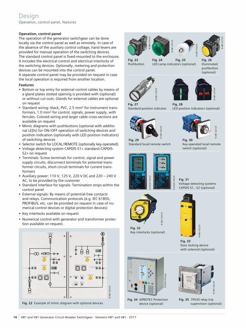
Fig. 22 Example of mimic diagram with optional devices
Fig. 23 Pushbutton
Fig. 24 Fig. 25 LED Lamp indicators (optional)
Fig. 26 Illuminated pushbutton (optional)
Fig. 27 Standard position indicator
Fig. 28 LED position indicators (optional)
Fig. 29 Standard local / remote switch
Fig. 30 Key-operated local / remote switch (optional)
Fig. 35 7PA30 relay trip supervision (optional)
Fig. 34 SIPROTEC Protection device (optional)
R-H
A35-
155.
tif
R-H
A35-
154.
tif
Fig. 31 Voltage detecting systems CAPDIS-S1, -S2 (optional)
R-H
B1-0
24.ti
f
Fig. 32 Key interlocks (optional)
R-H
B1-0
22.ti
f
Fig. 33 Door locking device with solenoid (optional)
R-H
HA-
102.
eps
R-H
B1-0
23.ti
f
R-H
B1-0
25.ti
f
R-H
B1-0
18.ti
f
16 HB1 and VB1 Generator Circuit-Breaker Switchgear · Siemens HB1 and VB1 · 2017
DesignOperation, control panel, features
Operation, control panelThe operation of the generator switchgear can be done locally via the control panel as well as remotely. In case of the absence of the auxiliary control voltage, hand levers are provided for manual operation of the switching devices.The standard control panel is fixed-mounted to the enclosure. It includes the electrical control and electrical interlocks of the switching devices. Optionally, metering and protection devices can be mounted into the control panel.A separate control panel may be provided on request in case the local operation is required from another location.Features• Bottom or top entry for external control cables by means of
a gland plates slotted opening is provided with (optional) or without cut-outs. Glands for external cables are optional on request
• Standard wiring: black, PVC, 2.5 mm2 for instrument trans-formers, 1.0 mm2 for control, signals, power supply, with ferrules. Colored wiring and larger cable cross-sections are available on request
• Mimic diagrams with pushbuttons (optional with additio-nal LEDs) for ON / OFF operation of switching devices and position indication (optionally with LED position indicators) of switching devices
• Selector switch for LOCAL / REMOTE (optionally key-operated).• Voltage detecting system CAPDIS-S1+ standard / CAPDIS-
S2+ on request• Terminals: Screw terminals for control, signal and power
supply circuits, disconnect terminals for potential trans-former circuits, short-circuit terminals for current trans-formers
• Auxiliary power: 110 V, 125 V, 220 V DC and 220 – 240 V AC, to be provided by the customer
• Standard interface for signals: Termination strips within the control panel
• External signals: By means of potential-free contacts and relays. Communication protocols (e.g. IEC 61850, PROFIBUS, etc. can be provided on request in case of nu-merical control devices or digital protection devices)
• Key interlocks available on request• Numerical control with generator and transformer protec-
tion available on request.
M
M
and/or
or
and/or
and/or
or
and/or
and/or
or
and/or
and/orand/or
and/or
and/or
G
M
M
and/or
and/or
or
and/or
and/or
or
and/or
and/or
M
and/or
and/or
or
and/or
and/or
or
or
and/or
and/or
and/or
or
and/or
and/or
or
or
and/or
M
and/or
and/or
or
and/or
and/or
or
or
and/or
and/or
and/or
and/or
or
and/or
and/orand/or
and/or
or
HB1
-001
4a_e
n ep
s
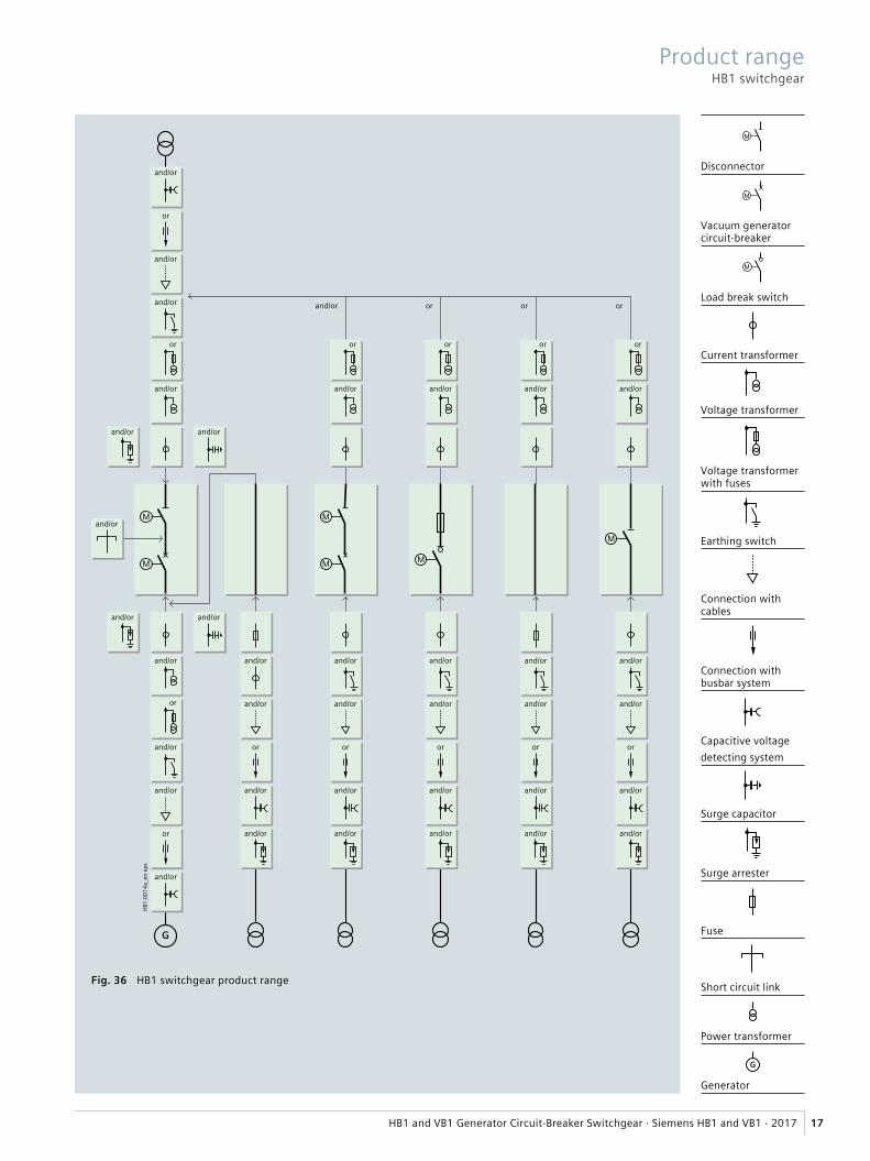
Fig. 36 HB1 switchgear product range
Disconnector
Vacuum generator circuit-breaker
Load break switch
Current transformer
Voltage transformer
Voltage transformer with fuses
Earthing switch
Connection with cables
Connection with busbar system
Capacitive voltagedetecting system
Surge capacitor
Surge arrester
Fuse
Short circuit link
Power transformer
Generator
17HB1 and VB1 Generator Circuit-Breaker Switchgear · Siemens HB1 and VB1 · 2017
Product rangeHB1 switchgear

Fig. 37 HB1 switchgear product range
M
M
and/or
or
and/or
and/or
or
and/or
and/or
or
and/or
and/orand/or
and/or
and/or
and/or
or
and/or
and/or
or
and/or
G
M
M
and/or
and/or
or
and/or
and/or
or
and/or
and/or
M
and/or
and/or
or
and/or
and/or
or
and/or
and/or
and/or
and/or
or
and/or
and/or
or
and/or
and/or
M
and/or
and/or
or
and/or
and/or
or
and/or
and/or
HB1
-001
5b_e
n ep
s
and/or and/or
and/or
18 HB1 and VB1 Generator Circuit-Breaker Switchgear · Siemens HB1 and VB1 · 2017
Product rangeVB1 switchgear

Disconnector
Vacuum generator circuit-breaker
Load break switch
Current transformer
Voltage transformer
Voltage transformer with fuses
Earthing switch
Connection with cables
Connection with busbar system
Capacitive voltagedetecting system
Surge capacitor
Surge arrester
Fuse
Short circuit link
Earthing or Excita-tion transformer
Power transformer
Generator
M
M
and/or
or
and/or
and/or
or
and/or
and/or
or
and/or
and/orand/or
and/or
HB1
-001
6b_e
n ep
s
and/or and/or
or
and/or
M
or
and/or
and/or
HB1
-001
7b_e
n ep
s
M
19HB1 and VB1 Generator Circuit-Breaker Switchgear · Siemens HB1 and VB1 · 2017
Product rangeVB1 switchgear

20 HB1 and VB1 Generator Circuit-Breaker Switchgear · Siemens HB1 and VB1 · 2017
Vacuum circuit-breakerThe vacuum circuit-breaker consists of the pole assemblies and the operating mechanism box. The pole assemblies are fixed to the operating mechanism box via post insula-tors. The switching movement is transferred by means of operating rods and levers.Switching mediumThe vacuum switching technology, proven and fully developed for more than 40 years, serves as arc-quenching principle by using vacuum interrupters.Pole assembliesThe pole assemblies consist of the vacuum interrupters and the interrupter supports. The vacuum interrupters are air-insulated and freely accessible. This makes it possible to clean the insulating parts easily in adverse ambient condi-tions. The vacuum interrupter is mounted rigidly to the upper interrupter support. The lower part of the interrupter is guided in the lower interrupter support, allowing axial movement. The braces absorb the external forces resulting from switching operations and the contact pressure.Operating mechanism boxThe whole operating mechanism with releases, auxiliary switches, indicators and actuating devices is accommo-dated in the operating mechanism box. The extent of the secondary equipment depends on the case of application and offers a multiple variety of options in order to meet almost every requirement.Operating mechanismThe operating mechanism is a stored-energy mechanism. The closing spring is charged either electrically or manually. It latches tight at the end of the charging process and serves as an energy store. The force is transmitted from the operat-ing mechanism to the pole assemblies via operating rods.To close the breaker, the closing spring can be unlatched either mechanically by means of the local “ON” pushbutton or electrically by remote control. The closing spring charges the opening or contact pressure springs as the breaker closes. The now discharged closing spring will be charged again automatically by the mechanism motor or manually.Then the operating sequence OPEN-CLOSE-OPEN is stored in the springs. The charging state of the closing spring can be checked electrically by means of a position switch.Trip-free mechanism3AH3 vacuum circuit-breakers have a trip-free mechanism according to IEC 62271-100. In the event of an opening command being given after a closing operation has been initiated, the moving contacts return to the open position and remain there even if the closing command is sus-tained. This means that the contacts of the vacuum circuit-breakers are momentarily in the closed position, which is permissible according to IEC 62271-100.ReleasesA release is a device which transfers electrical commands from an external source, such as a control room, to the latching mechanism of the vacuum circuit-breaker so that it can be opened or closed. Apart from the closing solenoid, the maximum possible equipment is one shunt release and two other releases.
• The closing solenoid unlatches the charged closing spring of the vacuum circuit-breaker, closing it by electri-cal means. It is suitable for DC or AC voltage.
• Shunt releases are used for automatic tripping of vacuum circuit-breakers by suitable protection relays and for de-liberate tripping by electrical means. They are intended for connection to an external power supply (DC or AC voltage) but, in special cases, may also be connected to a voltage transformer for manual operation.
• Current-transformer operated releases comprise a stored energy mechanism, an unlatching mechanism and an electro-magnetic system. They are used when there is no external source of auxiliary power (e.g. a battery). Tripping is effected by means of a protection relay (e.g. overcurrent-time protection) acting on the current-trans-former operated release.
When the tripping current is exceeded (= 90 % of the rated normal current of the c.t.-operated release), the latch of the energy store, and thus opening of the circuit-breaker, is released.• Undervoltage releases comprise a stored-energy mecha-
nism, an unlatching mechanism and an electromagnetic system which is permanently connected to the secondary or auxiliary voltage while the vacuum circuit-breaker is closed. If the voltage falls below a predetermined value, unlatching of the release is enabled and the circuit-break-er is opened via the stored-energy mechanism. The delib-erate tripping of the undervoltage release generally takes place via an NC contact in the tripping circuit or via an NO contact by short-circuiting the magnet coil. With this type of tripping, the short-circuit current is limited by the built-in resistors. Undervoltage releases can also be connected to voltage transformers. When the operating voltage drops to impermissibly low levels, the circuit-breaker is tripped automatically. For delayed tripping, the undervolt-age release can be combined with energy stores.
ClosingIn the standard version, 3AH3 vacuum circuit-breakers can be remote closed electrically. They can also be closed locally by mechanical unlatching of the closing spring via pushbutton. Instead of this “manual mechanical closing”, “manual electrical closing” is also available. In this ver-sion, the closing circuit of the circuit-breaker is controlled electrically by a pushbutton instead of the mechanical but-ton. In this way, switchgear-related interlocks can also be considered for local operation in order to prevent involun-tary closing.If constant CLOSE and OPEN commands are present at the circuit-breaker at the same time, the circuit-breaker will return to the open position after closing. It remains in this position until a new CLOSE command is given. In this manner, continuous closing and opening (= “pumping”) is prevented.Circuit-breaker tripping signalThe NO contact makes brief contact while the vacuum cir-cuit-breaker is opening, and this is often used to operate a hazard-warning system which, however, is only allowed to respond to automatic tripping of the circuit-breaker. There-fore, the signal from the NO contact must be interrupted when the circuit-breaker is being opened intentionally. This is accomplished under local control with the cut-out switch that is connected in series with the NO contact.
ComponentsVacuum circuit-breaker

R-H
B1-0
26.ti
f
R-H
G-1
1-21
8.tif
Fig. 38 3AH38 / 37 generator vacuum circuit-breaker, side view Fig. 39 3AH38 / 37 generator vacuum circuit-breaker, front view
21HB1 and VB1 Generator Circuit-Breaker Switchgear · Siemens HB1 and VB1 · 2017
Due to the modular design of the circuit-breakers, the best materials can be used each for the current path, electric flux and cooling. Thus, the 3AH37/38 circuit-breakers com-bine low resistance of the main circuit with high mechani-cal stability and ideal cooling performance.
Moreover, the modular design enables even horizontal installation of the circuit-breaker, if required. To do this, cooling elements can be installed which are provided especially for this mounting position. Thus, the 3AH37/38 can be operated continuously in any position without addi-tional fans, reliably excluding any overheating.
Features of the 3AH38/37 generator vacuum circuit-break-ers:• Type tested according to IEEE standard C37.013• High DC components > 65 %• Maintenance-free for 10,000 operating cycles• MTTF (mean-time-to-failure) > 50,000 years
(Values of the vacuum interrupters)• No toxic decomposition products of the arc quenching
medium.
Ud = Rated short-duration power-frequency withstand voltage
Electrical dataRated short-circuit breaking current ISC (3 s) kA 50 63 72
DC component of the rated short-circuit breaking current
% 75 65 65
Asymmetrical breaking current kA 73 86 98
Rated short-circuit making current kA 137 173 197
Generator short-circuit breaking current ISC gen kA 25 31.5 36
DC component of the short-circuit breaking current % 110 130 130 110
Asymmetrical breaking current kA 46 52 66 67
Rated currents A 3150, 4000, 5000, 6300, 8000 (with forced cooling)
Rated voltages17.5 kV (IEC 62271); 15.5 kV (IEEE C37.013a) 50 / 60 Hz; Up = 110 kV; Ud = 50 kV
3AH3817 (≤ 4000 A)
3AH3712 (> 4000 A)
3AH3818 (≤ 4000 A)
3AH3713 (> 4000 A)
3AH3819 (≤ 4000 A)
3AH3714 (> 4000 A)
24 kV (IEC 62271; IEEE C37.013a) 50 / 60 Hz; Up = 125 kV; Ud = 60 kV
3AH3722 (≤ 4000 A)
3AH3722 (> 4000 A)
3AH3723 3AH3724
Rated operating sequence
– at short-circuit breaking current CO – 30 min – CO, up to 30 short-circuit breaking operations Further operating sequences possible:
O – 3 min – CO – 3 min – CO
– at normal current O – 3 min – CO – 3 min – CO, up to 10,000 operating cycles
Up = Rated lightning impulse withstand voltage
ComponentsGenerator vacuum circuit-breaker

R-H
B1-0
37.p
dfR-
HB1
-038
.tif
R-H
B1-0
36.p
df
Fig. 40 Disconnector
Fig. 41 Earthing switch
Fig. 42 Fused load break switch
22 HB1 and VB1 Generator Circuit-Breaker Switchgear · Siemens HB1 and VB1 · 2017
ComponentsDisconnectors, fused load break switches and earthing switches
Disconnectors, fused load break switches and earthing switches
Disconnectors are used to electrically isolate the switch-gear or the associated equipment (e.g. generator, main transformer, etc.) from the network, in order to guarantee safe maintenance or repair work where it is required.
For each fixed-mounted vacuum circuit-breaker, an associ-ated disconnector is provided. Switching of the disconnec-tors must take place under no-load conditions.
Fused load break switches are used to protect and switch transformers < 1250 kVA.
Earthing switches are used to connect the switchgear’s busbar or the associated equipment (e.g. generator, main transformer, etc.) to earth, in order to guarantee safe maintenance or repair work where it is required.
Disconnectors, fused load break switches and earthing switches are designed in accordance with the requirements of EN 62271-102. A motor operating mechanism attach-ment enables actuation independent of the operator, with a switching angle of 90°.
One isolating blade is inserted into the impact contact per pole for the disconnector.
One earthing blade is inserted into the earth terminal per earthing pole for the earthing switch.
The switch positions OPEN or CLOSED are available as potential-free switch signals for each pole via an auxiliary switch and wired to the terminals in the control panel.
The operation can be done electrically (local and remote) or manually by means of a hand crank for operating the motor operating mechanism from outside the switchgear.
Mechanical class (in accordance with EN 62271-102) for the disconnector: Class M1 = 2000 mechanical switching operations.
Mechanical class (in accordance with EN 62271-102) for the fused load break switch: Class M1 = 2000 mechanical switching operations.
Mechanical class (in accordance with EN 62271-102) for the earthing switch: Class M0 = 1000 mechanical switching operations.
Electrical class (in accordance with EN 62271-102) for the earthing switch: Class E0 = no short-circuit making capacity Class E1 = short-circuit making capacity (optional).

R-H
B1-0
30.ti
f
Tite
l-HG
-12-
31.ti
f
R-H
G12-
022.
eps
Fig. 47 Window-type current transformer
R-H
B1-0
28.e
ps
R-H
B1-0
27.ti
f
Fig. 44 Surge capacitor
Fig. 45 Surge arrester type 3EL2
Fig. 50 Fuses for transformer protection
Fig. 48 Voltage transformer, fixed-mounted
Fig. 49 Voltage transformer, fixed-mounted with primary fuses
Fig. 51 Fuse holder
R-H
G24_
057.
psd
R-H
A25-
357.
psd
R-H
B1-0
29.ti
f
Fig. 43 Surge arrester type 3EK7
Fig. 46 Block-type current transformer up to 4000 A
R-H
A25-
347.
eps
23HB1 and VB1 Generator Circuit-Breaker Switchgear · Siemens HB1 and VB1 · 2017
ComponentsSurge arresters, capacitors, current and voltage transformers, fuses
Surge arresters, capacitorsGenerator vacuum circuit-breakers do not require addi-tional capacitors or surge arresters to withstand the sys-tem inherent rate-of-rise of recovery voltage.For other system phenomena, such as overvoltages transferred via the step-up transformer or transmission of zero-sequence voltages via the step-up transformer, it is recommended to install surge arresters and surge capacitors on the step-up transformer side terminals of the generator breaker. The system designer is responsible to ensure that these stresses are limited to permissible values because such phenomena must be taken into account for all the electrical equipment primarily thinking of the step-up transformer itself and finally of the generator which are the most expensive electrical devices of the system. The vacuum generator circuit-breaker will not be negatively influenced or will not change its proper switching behav-ior if surge capacitors and surge arresters are installed on the line side terminals of the switchgear. Additional surge capacitors and arresters can be provided on the genera-tor side terminals, too. Surge arresters with line discharge class 1 to 4 are available (3.5 kJ / kV to 10 kJ / kV).Independent of the size of the generator or transformer, surge capacitors with capacitances of 250 nF up to 300 nF per phase, may be considered appropriate to ensure safe limitation of the possible stresses without proving this by detailed calculations.
Current transformersFeatures:
– Cast-resin insulated – Max. operating voltage up to 24 kV – Max. rated primary current up to 8000 A – Max. rated short-time thermal current up to 72 kA, 1 s – Max. rated peak withstand current up to 180 kA – Max. 4 secondary cores – Very large range of accuracy class combinations – Secondary multiratio possible – Current transformer certifiable – Block type up to 4000 A and window type up to 8000 A.
Voltage transformersFeatures:
– Cast-resin insulated, single-pole – Primary operating voltage up to 24 kV – Max. secondary operating voltage up to 120 V or divided by 3
– Very large range of accuracy class combinations – Rating up to 200 VA – Earth-fault winding optional with damping resistor.
FusesFeatures:
– Made with porcelain tubes – Used in voltage transformers or to protect power trans-formers
– Silver melting elements and terminals – For load break switch application, there is a striker pin, which activates the trip mechanism with a release force of 80 N.

24 HB1 and VB1 Generator Circuit-Breaker Switchgear · Siemens HB1 and VB1 · 2017
Example:3000 m site altitude above sea level 17.5 kV switchgear rated voltage 95 kV rated lightning impulse withstand voltageRated lightning impulse withstand voltage to be selected = 95 kV · 1.28 = 122 kV
Result: According to the above table, a switchgear for a rated voltage of 24 kV with a rated lightning impulse withstand voltage of 125 kV is to be selected.
Table – dielectric strengthRated voltage (r.m.s. value) kV 12 17.5 24Rated short-duration power-frequency withstand voltage (r.m.s. value)– Between phases and to earth kV 28 38 50– Across isolating distances kV 32 45 60Rated lightning impulse withstand voltage (peak value)– Between phases and to earth kV 75 95 125– Across isolating distances kV 85 110 145
Altitude correction factor Ka
For site altitudes above 1000 m, the altitude cor-rection factor Ka is recommended, depending on the site altitude above sea level.
Rated short-duration power-frequency withstand voltage to be selected for site altitudes > 1000 m≥ Rated short-duration power-frequency withstand voltage up to ≤ 1000 m · Ka
Rated lightning impulse withstand voltage to be selected for site altitudes > 1000 m≥ Rated lightning impulse withstand voltage up to ≤ 1000 m · Ka
Type of service location
The switchgear can be used as indoor installation accord-ing to IEC 61936 (Power installations exceeding AC 1 kV) and VDE 0101• Outside lockable electrical service locations at places
which are not accessible to the public. Enclosures of switchgear can only be removed with tools
• In lockable electrical service locations. A lockable electri-cal service location is a place outdoors or indoors that is reserved exclusively for housing electrical equipment and which is kept under lock and key. Access is restricted to authorized personnel and persons who have been properly instructed in electrical engineering. Untrained or unskilled persons may only enter under the super-vision of authorized personnel or properly instructed persons.
Dielectric strength• The dielectric strength is verified by testing the switch-
gear with rated values of short-duration power-frequen-cy withstand voltage and lightning impulse withstand voltage according to IEC 62271-1 / VDE 0671-1 (see table “Dielectric strength”)
• The rated values are referred to sea level and to normal atmospheric conditions (1013 hPa, 20 °C, 11 g/m3 humid-ity according to IEC 60071 and VDE 0111)
• The dielectric strength decreases with increasing alti-tude. For site altitudes above 1000 m (above sea level) the standards do not provide any guidelines for the insulation rating, but leave this to the scope of special agreements
• Site altitude – The dielectric strength of air insulation decreases with increasing altitude due to low air density. This reduction is permitted up to a site altitude of 1000 m according to IEC and VDE
– For site altitudes above 1000 m, a higher insulation level must be selected. It results from the multiplication of the rated insulation level for 0 to 1000 m with the altitude correction factor Ka.
StandardsStandards, specifications, guidelines

25HB1 and VB1 Generator Circuit-Breaker Switchgear · Siemens HB1 and VB1 · 2017
Climate and environmental influences
HB1 and VB1 switchgear are suitable for application in indoor installations under normal operating conditions as defined in the standard IEC 62271-1 as follows:• Max. value of ambient air temperature: + 45 °C,
Average value over a period of 24 h: + 40 °C• Minimum ambient air temperature: – 5 °C• Altitude of installation ≤ 1000 m• Average value of relative humidity
over a period of 24 h: ≤ 95 %, over a period of one month: ≤ 90 %
• Ambient air not significantly polluted by dust, corrosive gases, vapours or salt.
The switchgear may be used, subject to possible additional measures, under the following environmental influences:
– Natural foreign materials – Chemically active pollutants – Small animals
and the climate classes: – 3K3 – 3K5.
The climate classes are defined according to IEC 60721-3-3.
Overview of standards
Switchgear, enclosureVDE 0101 IEC 61936-1 Power installations exceeding 1 kV AC – Part 1: Common rules
VDE 0470-1 IEC 60529 Degree of protection provided by enclosures (IP-code)
VDE 0671-1 IEC 62271-1 Common specifications for high-voltage switchgear and controlgear standards
VDE 0671-200 IEC 62271-200 AC metal-enclosed switchgear and controlgear for rated voltages above 1 kV and up to including 52 kV (according to list of performed tests)
ComponentsIEC 61869-2 Instrument transformers Part 2: Additional requirements for current transformersIEC 61869-3 Instrument transformers Part 3: Additional requirement for inductive voltage transformers
VDE 0671-100 IEC 62271-100 High-voltage alternating-current circuit-breakersVDE 0671-102 IEC 62271-102 Alternating current disconnectors and earthing switchesVDE 0675-4 IEC 60099-4 Surge arresters: Metal-oxide surge arresters without gaps for AC systemsVDE 0682-415 IEC 61243-5 Voltage detecting systems
Generator circuit-breakerIEEE C37.013 IEEE standard for AC high-voltage generator circuit-breakers rated on a symmetrical current
basis. Amendment 1: Supplement for use with generators rated 10 – 100 MVA
IEEE/IEC 62271-37-013 Alternating-current generator circuit-breakers
Standards
The switchgear complies with the relevant standards and specifications applicable at the time of type tests. In accor-dance with the harmonization agreement reached by the countries of the European Union, their national specifica-tions conform to the IEC standard.
Current carrying capacity• According to IEC 62271-1 / VDE 0671-1 and IEC 62271-200 /
VDE 0671-200, the rated normal current refers to the following ambient air temperatures:
– Maximum of 24-hour mean + 40 °C – Maximum + 45 °C
• The rated normal current of the panels and busbars depends on the ambient air temperature outside the enclosure.
Protection against solid foreign objects, electric shock and water
HB1 and VB1 switchgear fulfill according to the standards – IEC 62271-200 – IEC 60529 – VDE 0470-1 – VDE 0671-200
the following degrees of protection:
Switchgear panel HB1 VB1Degree of protection for the enclosureoptionally
IP4X
IP41, IP42, IP54, IP55
IP4X
IP41, IP42, IP54, IP55Degree of protection for the partitions
N. A. IP2X
Degree of protection for the control paneloptionally
IP4X
IP54, IP55
IP4X
IP54, IP55
StandardsStandards, specifications, guidelines

R-H
B1-0
33-0
35.ti
fR-
HB1
-031
.tif
R-H
B1-0
32.ti
f
Fig. 53 Seismic test at an independent laboratory
Fig. 54 Internal arc test at an independent laboratory
Fig. 52 Personnel safety and reliability
26 HB1 and VB1 Generator Circuit-Breaker Switchgear · Siemens HB1 and VB1 · 2017
StandardsStandards, specifications, guidelines
Aseismic capacity
VB1 switchgear has been tested in accordance with the following internationally accepted requirements: IEEE 693, UBC Division IV.
Internal arc classification• Protection of operating personnel by means of tests for
verifying the internal arc classification• Internal arc tests must be performed in accordance with
IEC 62271-200 / VDE 0671-200• The switchgear complies with all criteria specified in the
standards (see page 25) for the basic version up to 72 kA• HB1 complies with the internal arc classification:
IAC A FLR up to 63 kA, 1 s• VB1 complies with the internal arc classification:
IAC A FLR up to 72 kA, 0.1 s.
This provides maximum personal safety of the switchgear accessible from all sides• Definition of criteria:
– Criterion 1 Correctly secured doors and covers do not open, limited deformations are accepted
– Criterion 2 No fragmentation of the enclosure, no projection of small parts above 60 g
– Criterion 3 No holes in accessible sides up to a height of 2 m
– Criterion 4 No ignition of indicators due to hot gases
– Criterion 5 The enclosure remains connected to its earthing point
• In addition to the internal arc tests, Siemens performs a pressure simulation.

Fig. 55 Example of a short-circuit simulation for the breaking capability confirmation
Three-phase short-circuit currentPhase T – first-pole-to-clear
HB1
-002
0_en
eps
Contact separation
Isc = 24.2 kA
tcp = 49 ms
tarc min = 4.4 ms
tarc total = 11 ms
Isc = 20.4 kA
Isc = 20.2 kA
DC 59 %
RST
–1000.000
–80
–60
–40
–20
0
20
40
60
80
100
0.020 0.040 0.060 0.080 0.100
Time
s
kA
Isc (t)
1st zero crossing
27HB1 and VB1 Generator Circuit-Breaker Switchgear · Siemens HB1 and VB1 · 2017
StandardsStandards, specifications, guidelines
Guidelines
You know your application. And we know the behavior and features of our switching devices. Together we work out the perfect solution for your application.
For this purpose, we kindly ask you to submit the following data:• Data sheets of:
– Generator – Transformer – Auxiliary transformer and motors, if applicable
• Single-line diagram• Information on equipment operation,
e.g. interconnected circuits.
Based on the information concerning your application, our experts select a circuit-breaker which reliably controls all service conditions, including tripping in the case of a fault. Among other things, the results of the calculations contain a graphical representation of the current characteristics, as shown below.

2017
Published by Siemens AG 2017
Energy Management Medium Voltage & Systems Mozartstraße 31 C 91052 Erlangen, Germany
For further information please contact our Customer Support Center Phone: +49 180 524 70 00 Fax: +49 180 524 24 71 E-mail: [email protected] siemens.com/medium-voltage-switchgear
Article No. IC1000-K320-A192-V2-7600 Printed in Germany Dispo 40401 PU 002163 KG 02.17 2.0
Subject to changes and errors. The information given in this document only contains general descriptions and / or performance features which may not always specifically reflect those described, or which may undergo modification in the course of further development of the products. The requested performance features are binding only when they are expressly agreed upon in the concluded contract.


![Cronología y declaraciones Comentado [HB1]: de los](https://img.pdfslide.net/doc/110x75/62c88f612d4f4a2e781cfce6/cronologa-y-declaraciones-comentado-hb1-de-los-.jpg)