Embed Size (px)
Citation preview
Generic Balanced Single Pair Cabling Infrastructure for Powering and Communication with IoT and IBS
Devices
Masood Shariff
OutlineWhat is generic single pair cabling infrastructure?Market trends and indicatorsTechnology and Standards Design and InstallationCables and ConnectorsQuality metrics and testingHow can BICSI members help?Conclusions and take away
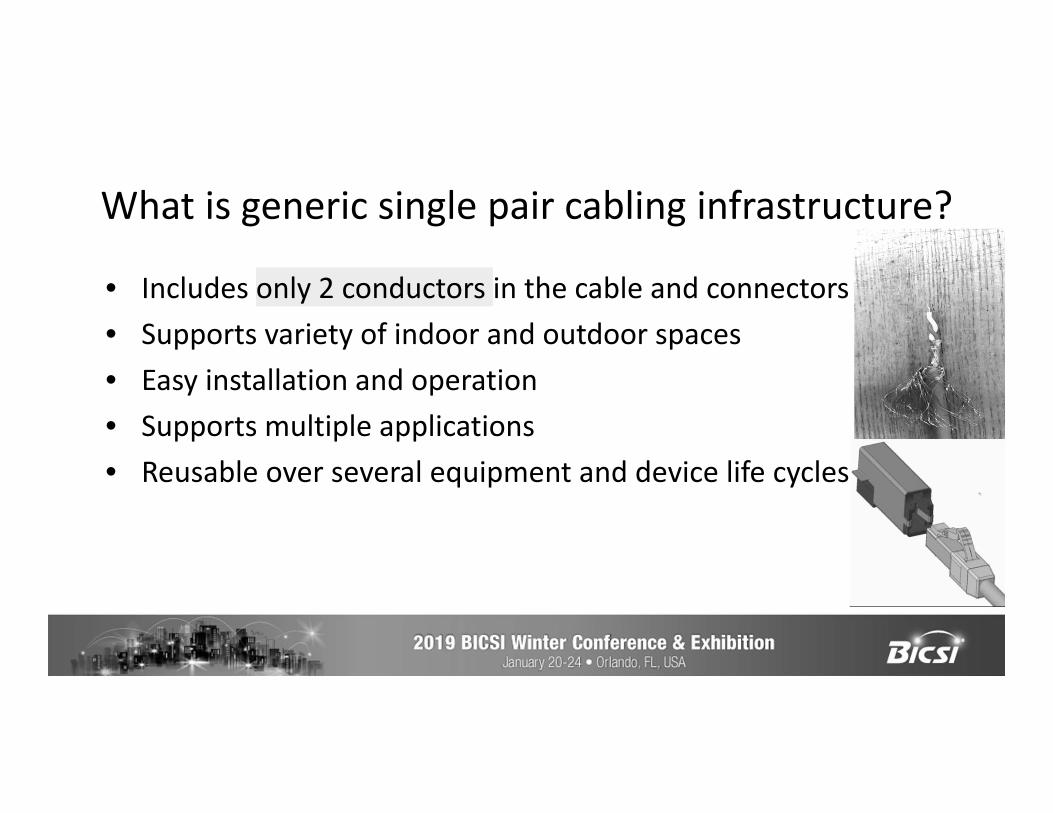
What is generic single pair cabling infrastructure?
• Includes only 2 conductors in the cable and connectors • Supports variety of indoor and outdoor spaces• Easy installation and operation• Supports multiple applications • Reusable over several equipment and device life cycles
What are IoT and IBS?
• A part of an equipment or device that enables communication with other similarly enabled devices
• Networked communication allows devices to work together in unison towards a common purpose ( e.g. energy efficiency, security, comfort, convenience)
Market Trends and Directions
5
Office of the futureSmart buildings and smart citiesInternet of things ( M2M communication)Efficiency and environmental sustainabilityPower and data over single pair cablingConvergence of IT and OT in some areasIoT market is predicted to be about USD 100 Billion in 4
years growing at about 10% CAGR ( next few slides)
Communication Technology study“According to the new market research report "Building Automation System Market by Communication Technology (Wired, and Wireless), Offering (Facilities Management Systems, Security & Access Control Systems, and Fire Protection Systems), Application, and Region - Global Forecast to 2022", the overall BAS market was valued at USD 53.66 Billion in 2016 and is expected to reach USD 99.11 Billion by 2022, at a CAGR of 10.73% between 2017 and 2022. The growth of this market is driven by the increase in demand for energy-efficient systems, growing need for the automation of security systems in buildings, and advancement of IoT in BAS”
Building Automation Systems Market“The global building automation system market was valued at USD 44,067 million in 2017, and is expected to reach a value of USD 82,517.4 million by 2023, recording a CAGR of 11% over the forecast period (2018-2023). The scope of this study has been restricted to hardware and software components used in building automation systems. The service segment has not been considered as part of the study scope.”
Orbis Research Study“According to Statistics MRC, Building Automation Market is estimated at $35.9 billion in 2015 and is expected to reach $67.1 billion by 2022 growing at a CAGR of 9.6% from 2015 to 2022. Strict government initiatives, growing demand for energy efficient systems & solutions, and increasing cost saving needs of the building owners have played a key role in boosting the market growth”
Research and Markets Report“According to this report, the Global Building Automation System (BAS) market is expected to grow from $59.43 billion in 2017 to reach $166.99 billion by 2026 with a CAGR of 12.1%. Rising in demand for energy-efficient systems, improvement of IoT in building automation system, growth of building automation-centric wireless protocols and wireless sensor network technology are some of the key factors fueling the market growth.”
Global Building Management System Market Analysis
“The Global Building Management System Market accounted to USD 54.0 billion in 2016 growing at a CAGR of 11.0% during the forecast period of 2017 to 2024.” ( USD 112.11 billion in 2024)
Common Standards based OT/BAS networks
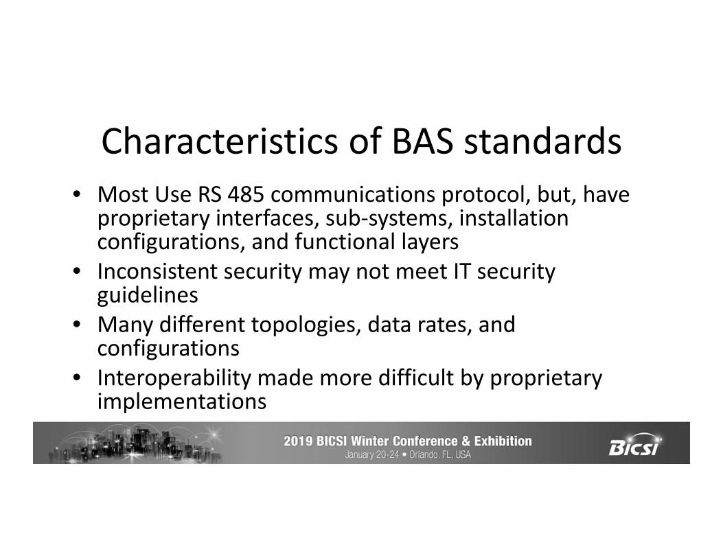
Characteristics of BAS standards• Most Use RS 485 communications protocol, but, have
proprietary interfaces, sub-systems, installation configurations, and functional layers
• Inconsistent security may not meet IT security guidelines
• Many different topologies, data rates, and configurations
• Interoperability made more difficult by proprietary implementations

• Developed by ASHRAE• Primarily for HVAC• MS/TP: References RS-485 specs which in
turn references TSB-89 for cablesDesign is vendor dependent
• LONTalk: see next slide
BACnet
Proprietary and Confidential. © 2013 Anixter Inc.
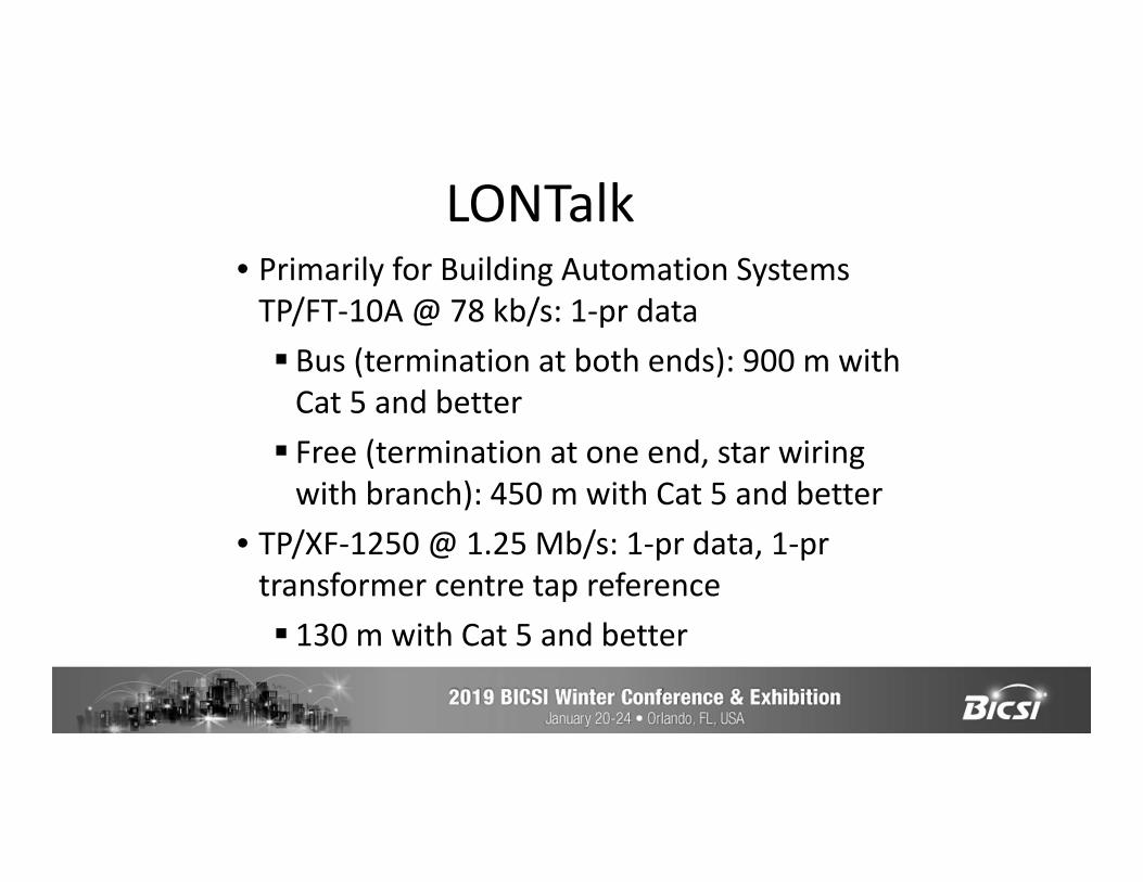
• Primarily for Building Automation Systems TP/FT-10A @ 78 kb/s: 1-pr data Bus (termination at both ends): 900 m with
Cat 5 and better Free (termination at one end, star wiring
with branch): 450 m with Cat 5 and better• TP/XF-1250 @ 1.25 Mb/s: 1-pr data, 1-pr
transformer centre tap reference 130 m with Cat 5 and better
LONTalk
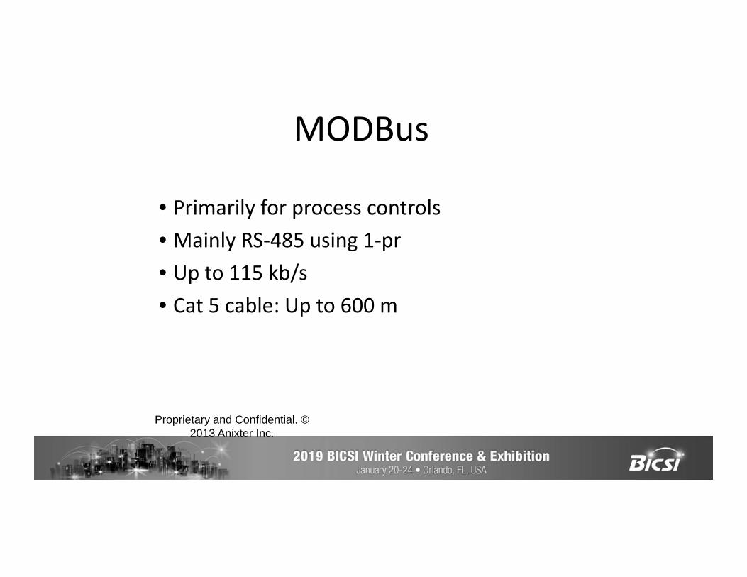
• Primarily for process controls• Mainly RS-485 using 1-pr• Up to 115 kb/s• Cat 5 cable: Up to 600 m
MODBus
Proprietary and Confidential. © 2013 Anixter Inc.
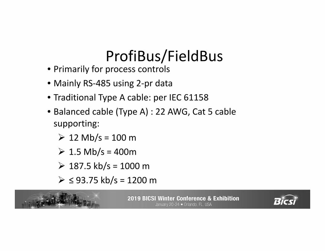
• Primarily for process controls• Mainly RS-485 using 2-pr data• Traditional Type A cable: per IEC 61158• Balanced cable (Type A) : 22 AWG, Cat 5 cable
supporting: 12 Mb/s = 100 m 1.5 Mb/s = 400m 187.5 kb/s = 1000 m ≤ 93.75 kb/s = 1200 m
ProfiBus/FieldBus
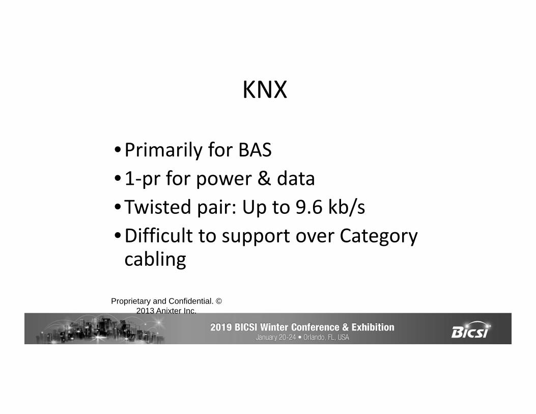
•Primarily for BAS•1-pr for power & data•Twisted pair: Up to 9.6 kb/s•Difficult to support over Category
cabling
KNX
Proprietary and Confidential. © 2013 Anixter Inc.
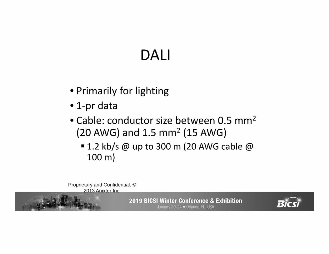
• Primarily for lighting• 1-pr data• Cable: conductor size between 0.5 mm2
(20 AWG) and 1.5 mm2 (15 AWG) 1.2 kb/s @ up to 300 m (20 AWG cable @
100 m)
DALI
Proprietary and Confidential. © 2013 Anixter Inc.
Examples of Company specific OT/BAS networks
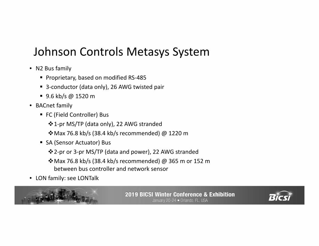
• N2 Bus family Proprietary, based on modified RS-485 3-conductor (data only), 26 AWG twisted pair 9.6 kb/s @ 1520 m
• BACnet family FC (Field Controller) Bus1-pr MS/TP (data only), 22 AWG strandedMax 76.8 kb/s (38.4 kb/s recommended) @ 1220 m
SA (Sensor Actuator) Bus2-pr or 3-pr MS/TP (data and power), 22 AWG strandedMax 76.8 kb/s (38.4 kb/s recommended) @ 365 m or 152 m
between bus controller and network sensor• LON family: see LONTalk
Johnson Controls Metasys System
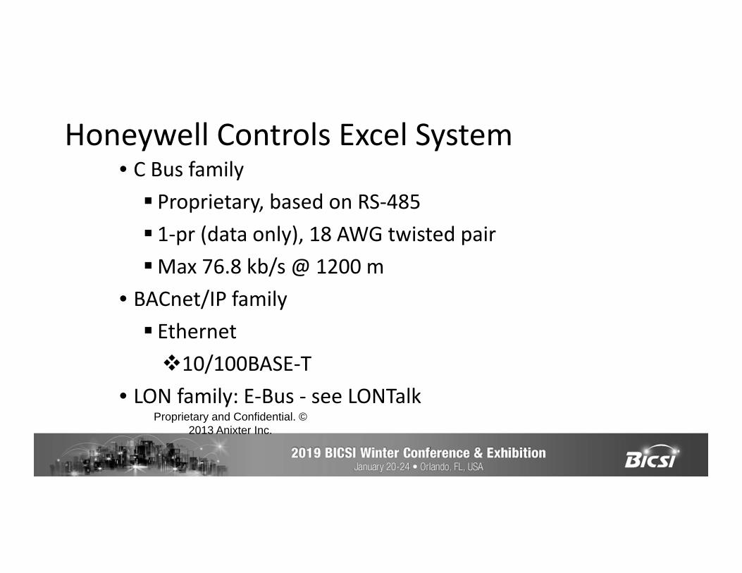
• C Bus family Proprietary, based on RS-485 1-pr (data only), 18 AWG twisted pairMax 76.8 kb/s @ 1200 m
• BACnet/IP family Ethernet10/100BASE-T
• LON family: E-Bus - see LONTalk
Honeywell Controls Excel System
Proprietary and Confidential. © 2013 Anixter Inc.
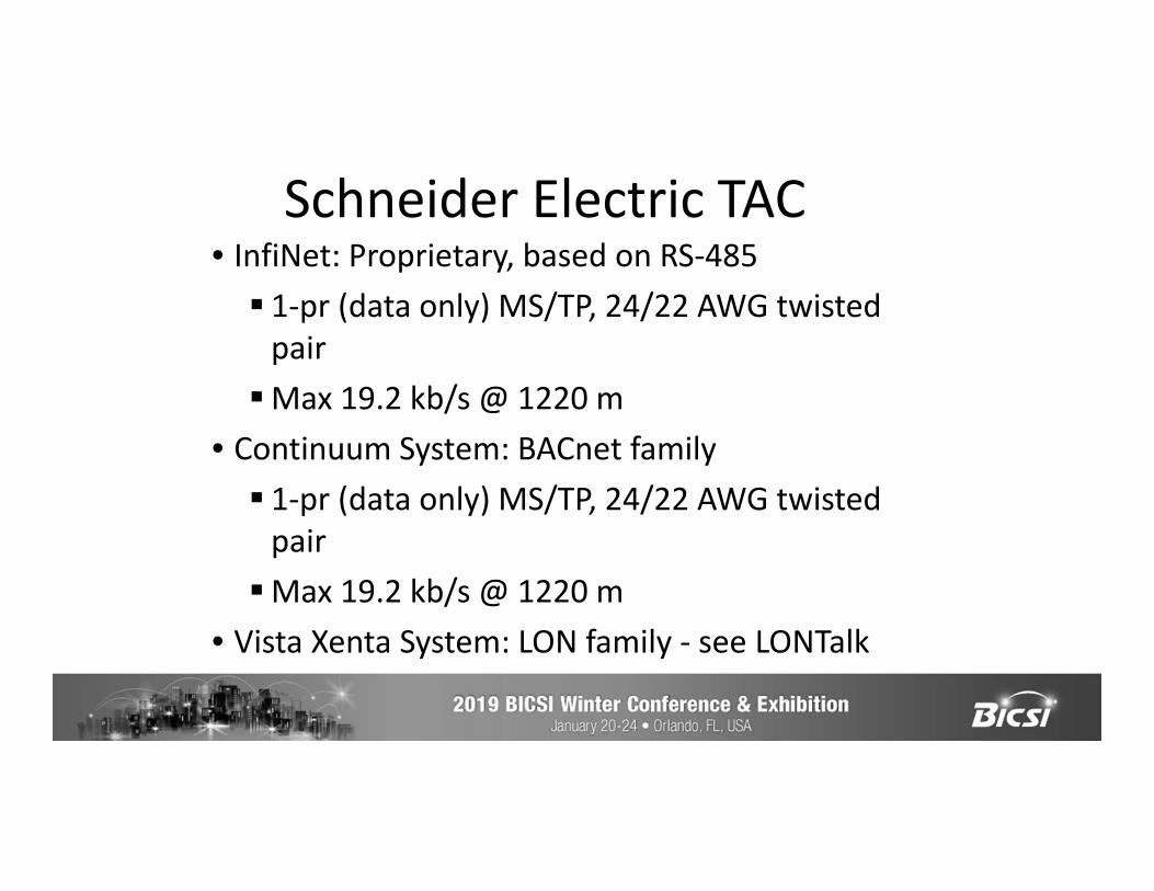
• InfiNet: Proprietary, based on RS-485 1-pr (data only) MS/TP, 24/22 AWG twisted
pairMax 19.2 kb/s @ 1220 m
• Continuum System: BACnet family 1-pr (data only) MS/TP, 24/22 AWG twisted
pairMax 19.2 kb/s @ 1220 m
• Vista Xenta System: LON family - see LONTalk
Schneider Electric TAC
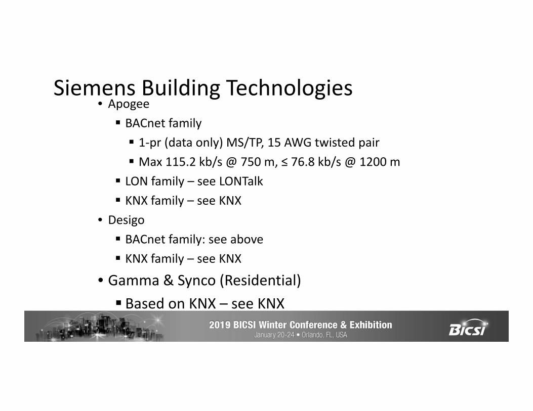
• Apogee BACnet family 1-pr (data only) MS/TP, 15 AWG twisted pair Max 115.2 kb/s @ 750 m, ≤ 76.8 kb/s @ 1200 m
LON family – see LONTalk KNX family – see KNX
• Desigo BACnet family: see above KNX family – see KNX
• Gamma & Synco (Residential) Based on KNX – see KNX
Siemens Building Technologies
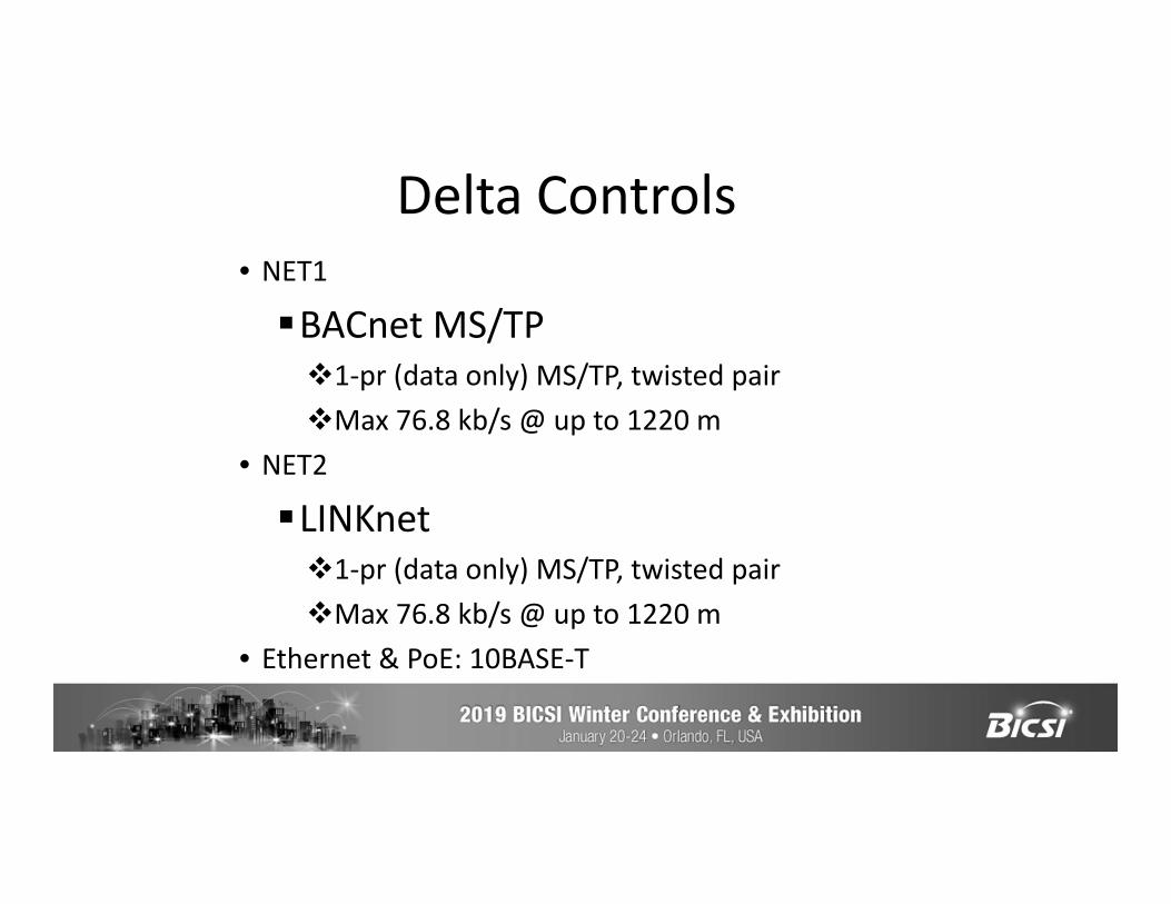
• NET1
BACnet MS/TP1-pr (data only) MS/TP, twisted pairMax 76.8 kb/s @ up to 1220 m
• NET2
LINKnet1-pr (data only) MS/TP, twisted pairMax 76.8 kb/s @ up to 1220 m
• Ethernet & PoE: 10BASE-T
Delta Controls
Creating an alternative single pair Ethernet Ecosystem for IT/OT/others

The move to Ethernet
Ethernet Switch
Ethernet Controllers
Ethernet Network
IOT/BAS Devices
BacknetDrops
Necessary Contents of an EcosystemIncludes at least the following:Clear scope and extentExisting and emerging application standardsCabling and component standardsDesign and installation guidelinesQuality metrics and testingAdministration and Operations
Single Pair Standards and Technology• IEEE 802.3 SPE projects• TIA TR42 cabling systems and components• ISO/IEC/JTC1/ SC25/WG 3 cabling systems• IEC SC46C cables, cords, and test instruments• IEC SC48B Connectors• CENELEC TC215 cabling systems NOTE: Standards have to fill in the details of the complete ecosystem including planning, design, installation, testing, and operations
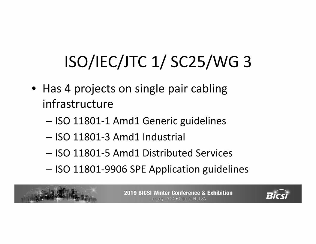
ISO/IEC/JTC 1/ SC25/WG 3• Has 4 projects on single pair cabling
infrastructure– ISO 11801-1 Amd1 Generic guidelines– ISO 11801-3 Amd1 Industrial– ISO 11801-5 Amd1 Distributed Services– ISO 11801-9906 SPE Application guidelines

TIA TR42 • TR42 has started 4 single pair projects
– TIA 568.5 Generic cabling and components– TIA 568.0-D Amd 1 Generic architecture– TIA 862-B Amd 1 Intelligent building systems (IBS)– TIA 1005-A Amd 3 Industrial
Designs and implementations
NetworkEquipment
4 Pair
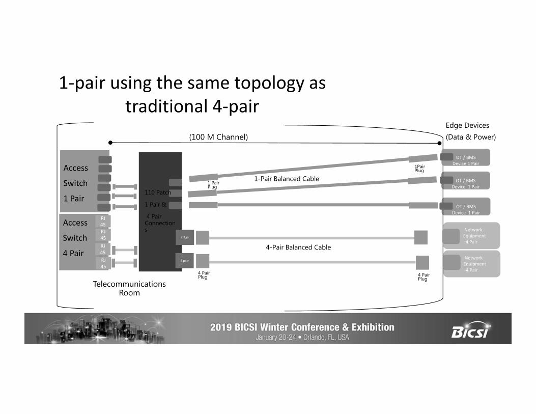
1-pair using the same topology as traditional 4-pair
OT / BMS Device 1 Pair
OT / BMS Device 1 Pair
RJ45
Telecommunications Room
(100 M Channel)
OT / BMS Device 1 Pair
Edge Devices(Data & Power)
Access
Switch
1 Pair
RJ45
RJ45RJ45
Access
Switch
4 Pair
110 Patch
1 Pair &
4 Pair Connections
4 Pair
4 pair
1-Pair Balanced Cable
1Pair Plug
NetworkEquipment
4 Pair
4 Pair Plug
4-Pair Balanced Cable
4 Pair Plug
1 Pair Plug
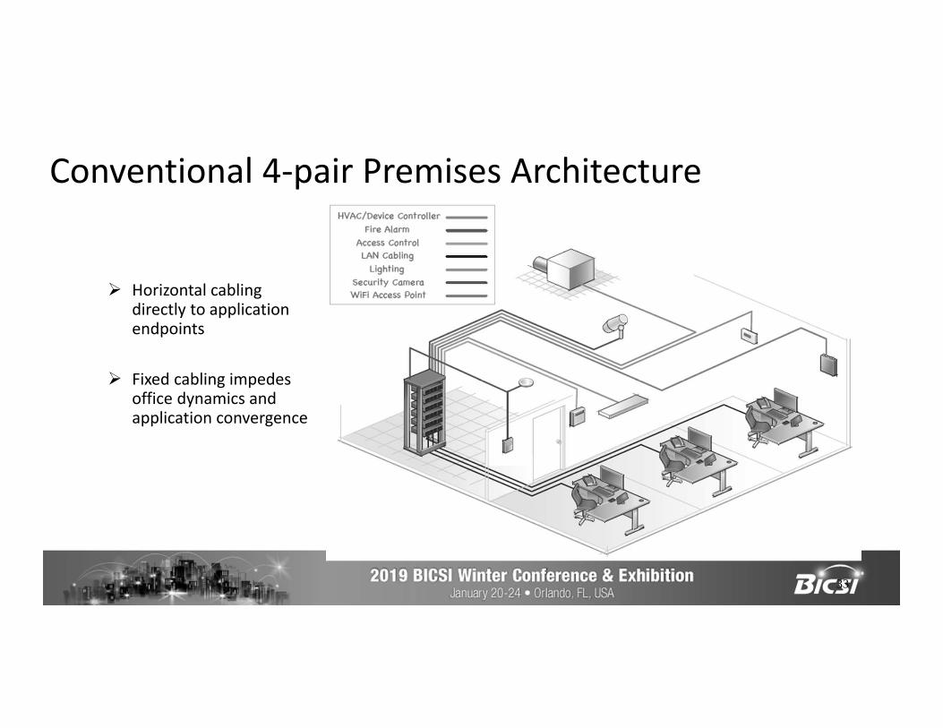
Conventional 4-pair Premises Architecture
33
Horizontal cabling directly to application endpoints
Fixed cabling impedes office dynamics and application convergence
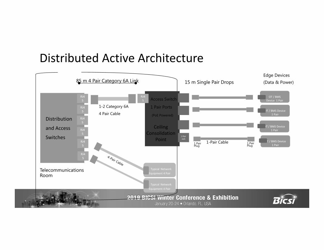
Distributed Active Architecture
Typical Network Equipment 4 Pair
RJ45
RJ45
RJ45
RJ45
1 Pair Jack
Access Switch
1 Pair Ports
(PoE Powered)
Telecommunications Room
85 m 4 Pair Category 6A Link
1-2 Category 6A
4 Pair Cable
1-Pair Cable 1 Pair Plug
1 Pair Plug
Edge Devices(Data & Power)
Ceiling Consolidation
Point
Distribution
and Access
Switches
Typical Network Equipment 4 Pair
RJ45
RJ45
RJ45
OT / BMS Device 1 Pair
OT / BMS Device 1 Pair
OT / BMS Device 1 Pair
OT / BMS Device 1 Pair
15 m Single Pair Drops
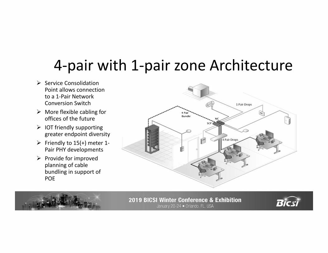
4-pair with 1-pair zone Architecture
35
Service Consolidation Point allows connection to a 1-Pair Network Conversion Switch
More flexible cabling for offices of the future
IOT friendly supporting greater endpoint diversity
Friendly to 15(+) meter 1-Pair PHY developments
Provide for improved planning of cable bundling in support of POE
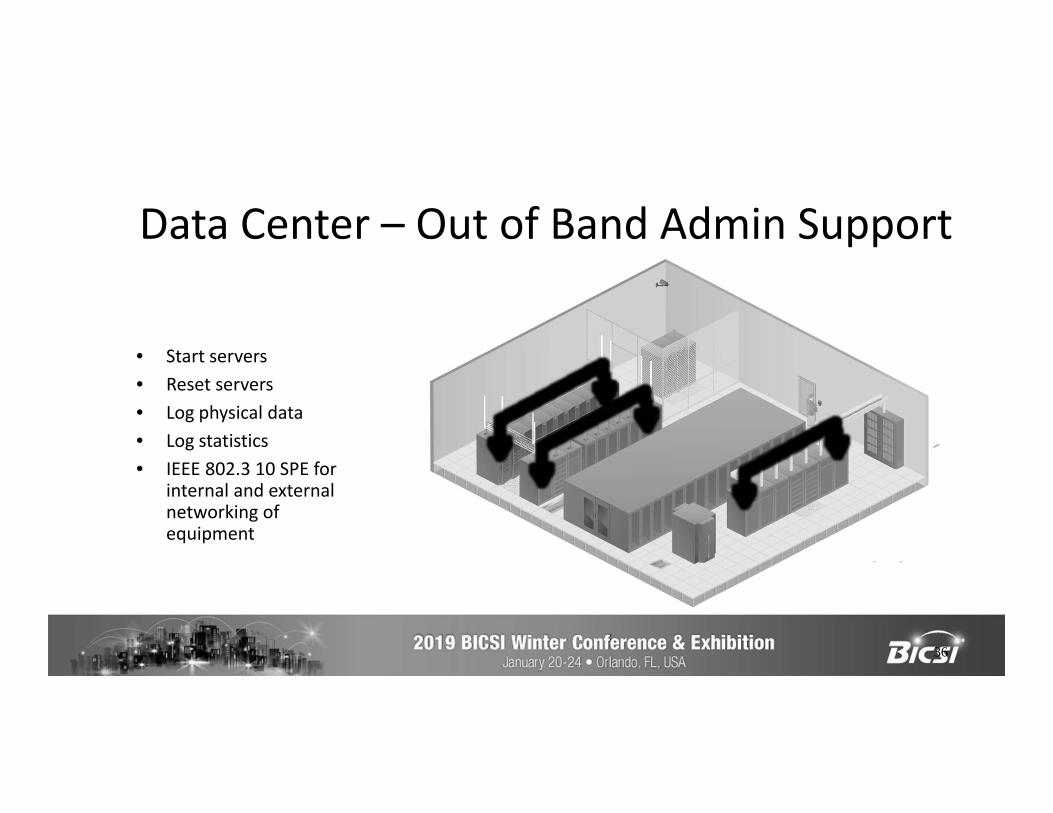
Data Center – Out of Band Admin Support
36
• Start servers• Reset servers• Log physical data• Log statistics• IEEE 802.3 10 SPE for
internal and external networking of equipment
IEEE 802.3cg Backplane applications
• IEEE 802.3cg 10 Mb/s SPE management networks on server and switch circuit boards (backplane)
• Monitor physical and electrical characteristics• Enable administration and management of circuit
board components• Can connect to external equipment using the
same 10 Mb/s SPE network
SPE Interoperability Testing
Jon Lewis & Jason Rock
Courtesy DELL-EMC
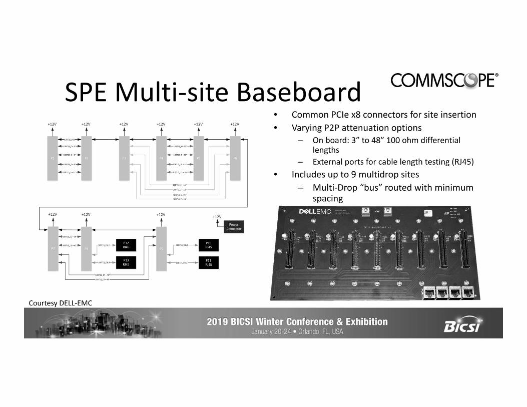
SPE Multi-site Baseboard• Common PCIe x8 connectors for site insertion• Varying P2P attenuation options
– On board: 3” to 48” 100 ohm differential lengths
– External ports for cable length testing (RJ45)• Includes up to 9 multidrop sites
– Multi-Drop “bus” routed with minimum spacing
Courtesy DELL-EMC
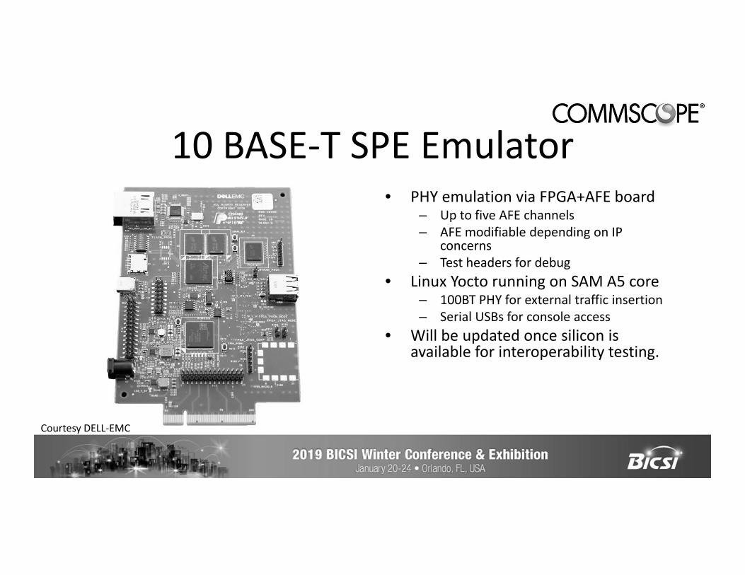
10 BASE-T SPE Emulator• PHY emulation via FPGA+AFE board
– Up to five AFE channels– AFE modifiable depending on IP
concerns– Test headers for debug
• Linux Yocto running on SAM A5 core– 100BT PHY for external traffic insertion– Serial USBs for console access
• Will be updated once silicon is available for interoperability testing.
Courtesy DELL-EMC
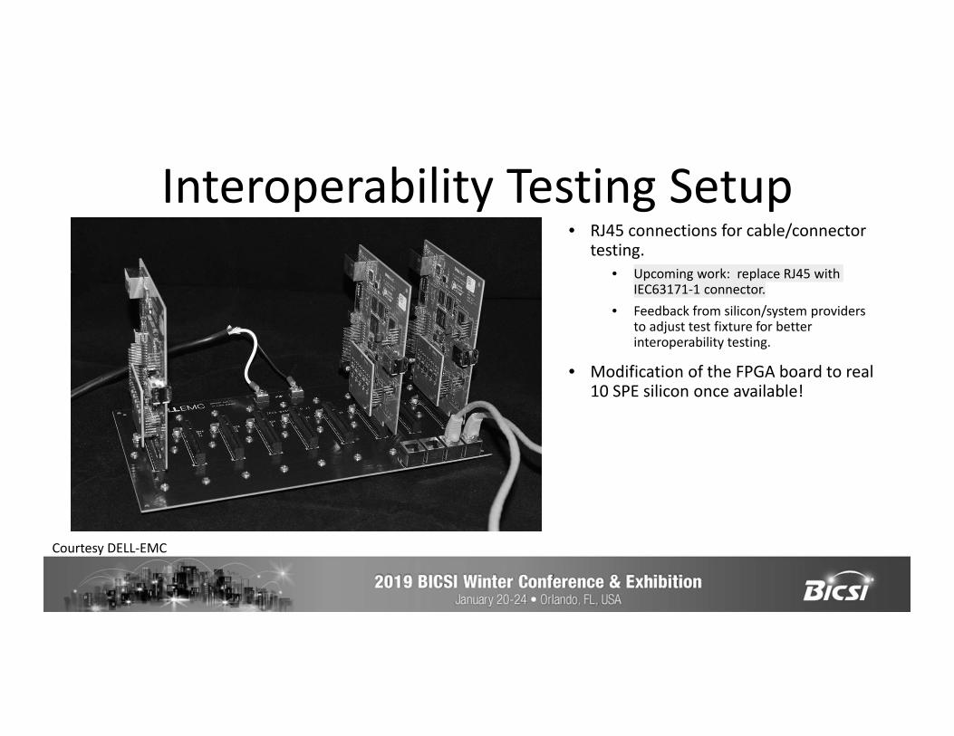
Interoperability Testing Setup• RJ45 connections for cable/connector
testing.• Upcoming work: replace RJ45 with
IEC63171-1 connector.• Feedback from silicon/system providers
to adjust test fixture for better interoperability testing.
• Modification of the FPGA board to real 10 SPE silicon once available!
Courtesy DELL-EMC

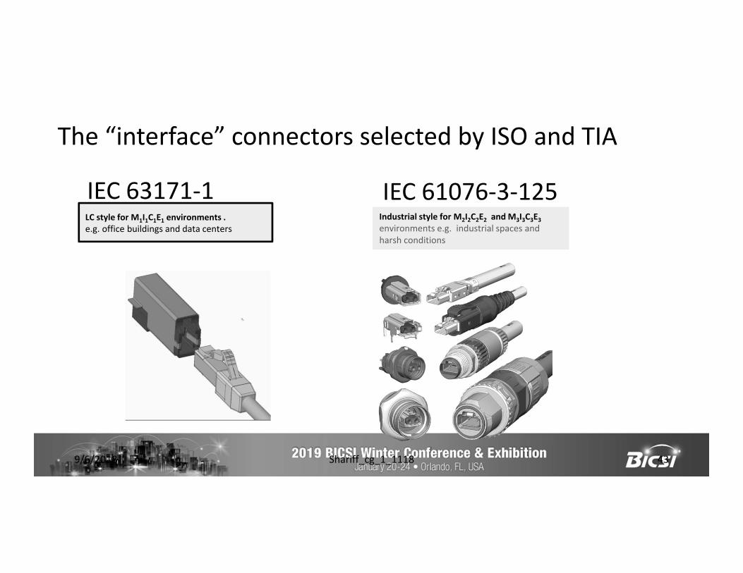
The “interface” connectors selected by ISO and TIA
IEC 63171-1 IEC 61076-3-125
9/6/2018 Shariff_cg_1_1118 43
LC style for M1I1C1E1 environments . e.g. office buildings and data centers
Industrial style for M2I2C2E2 and M3I3C3E3 environments e.g. industrial spaces and harsh conditions
What does cabling interface connector mean ?
• Applies only at the two ends of the link segment• Does not apply to any other connectors in the link segment• Interface connectors need larger number of mating cycles
(> 750)• Interface connectors can be subject to mating and un-
mating under load ( 2 A per contact)• Need to have repeatable and consistent electrical &
mechanical plug and jack interoperability from multiple suppliers
11/11/2018 Shariff_cg_1_1118 44
Advantages of using the same interface for cabling and MDI
• Connector specifications are developed by IEC SC48B experts with considerable expertise in mechanical specifications, electrical specifications, reliability specifications, testing and EMC specifications– IEC SC48B is the expert committee for detailed connector specifications
• Do not need multiple adapter cords for connection to equipment from the installed cabling
• Improves the volume economics of both MDI and cable interface connectors
• Shared knowledge and technology will improve both cabling interfaces and equipment interfaces leading to positive benefits for both
11/11/2018 Shariff_cg_1_1118 45
Usability considerations and advantages
• Cord can be plugged in without concern for end orientation making it easier to administer.
• Avoids mix ups, where one is choosing a cord by looking at the plugs. With the same plug on both ends, a look at either end means it is the same on the other end.
• Reduces the number of plug combinations ( experience with the USB cord variants with USB on one end and different equipment connectors at the other end).
• Advantage of plug designed for the “cabling interface” application at the outlet, will also be capable of repeated “mating” at the equipment.
9/6/2018 Shariff_cg_1_1118 46
Interoperability – A key standards requirement
IEC 63171-1 Copper LC connector interoperability
IEEE 802.3cg Task ForceSeptember 2018
Related to draft 2.0 ballot comments 572, 573, 618, 619, 653
Antoine Pelletier, IntertekMasood Shariff, CommScope
Jeff Oberski, CommScopeMike Borgman, Panduit
9/6/2018 pelletier_3cg_01_0918 48
Test plan overview• Two (2) manufacturers submitted four (4) pairs of copper LC
plug and jack (MDI).• Each connector pair from both manufacturer was measured
(resulting in 8 measurements).• The plug and jack specimen were interchanged between
both manufacturers and the mated performance measured (resulting in another 8 measurements).
• The IL, RL, TCL and TCTL results were compared against the IEC 63171-1 draft standard.
9/6/2018 pelletier_3cg_01_0918 49
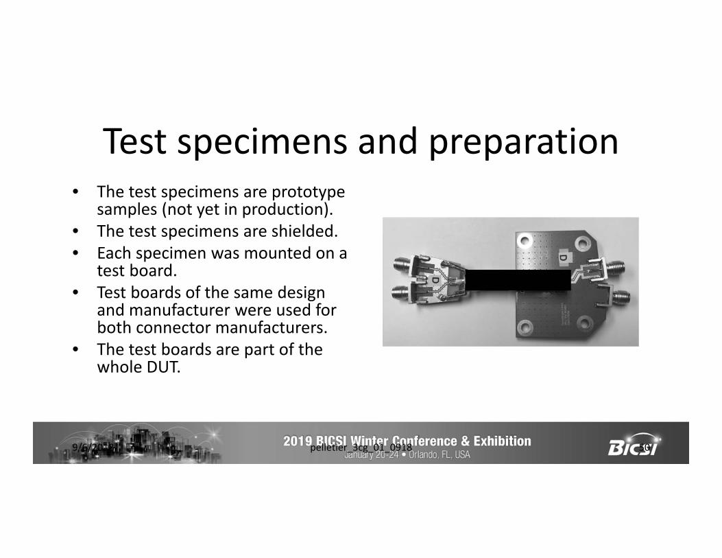
Test specimens and preparation• The test specimens are prototype
samples (not yet in production).• The test specimens are shielded.• Each specimen was mounted on a
test board.• Test boards of the same design
and manufacturer were used for both connector manufacturers.
• The test boards are part of the whole DUT.
9/6/2018 pelletier_3cg_01_0918 50
Network analyzer settings• Network analyzer: Keysight E5071C• IF BW: 200 Hz• Sweep type: Segment
– 300 kHz – 900 kHz, 7 points– 1 MHz – 1 001 MHz, 1 001 points
• Power level: 10 dBm• ECAL was used for calibration• Note: The particular network analyzer used has a start frequency of 300
kHz which is greater than the 100 kHz minimum frequency of the draft standard. The connectors are expected to meet the requirements below 300 kHz.
9/6/2018 pelletier_3cg_01_0918 51
Test results
• The test results are presented in the following eight (8) slides (4 parameters * 2 directions).
• For each parameters, all sixteen (16) test results are superimposed.
• The test results are not identified as to which manufacturer combination they belong to.
9/6/2018 pelletier_3cg_01_0918 52
Test results
9/6/2018 pelletier_3cg_01_0918 53
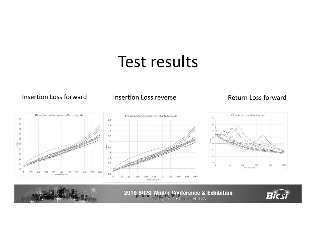
Insertion Loss forward Insertion Loss reverse Return Loss forward
Test results
9/6/2018 pelletier_3cg_01_0918 54
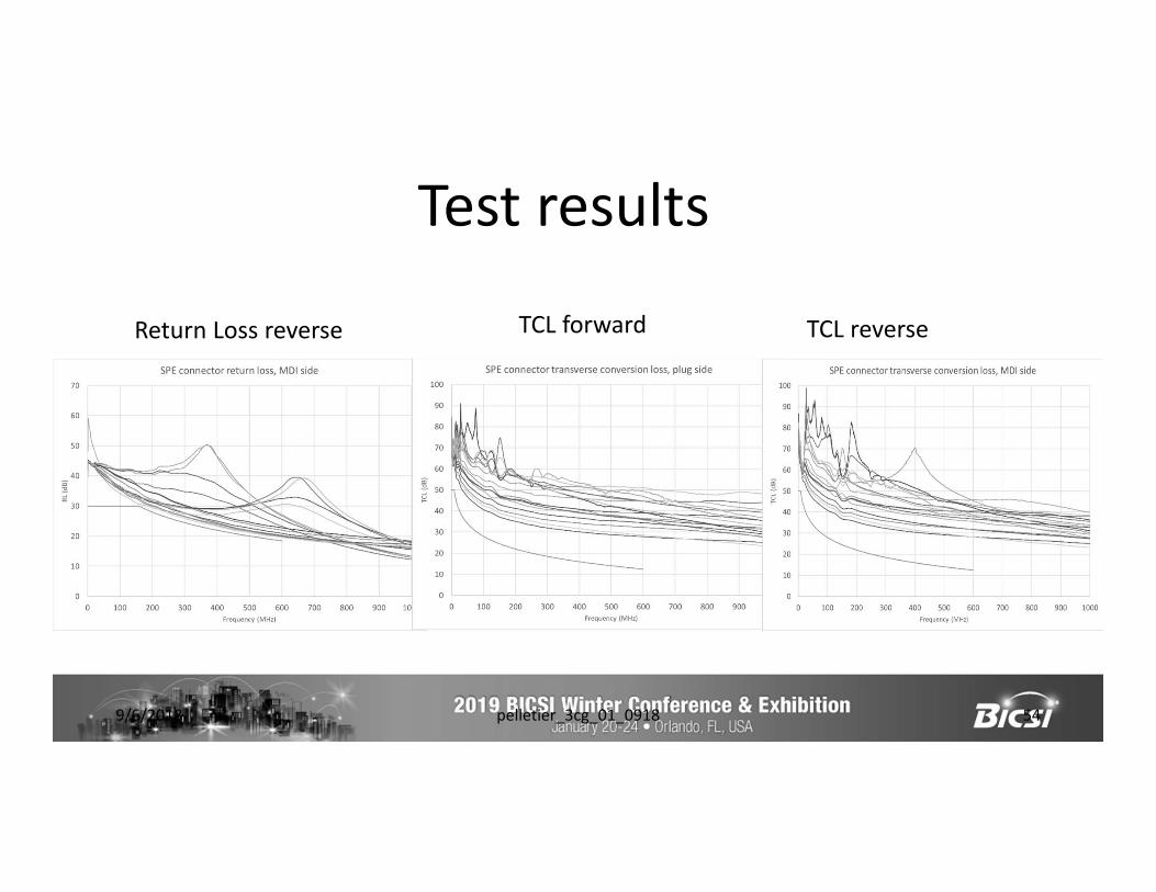
TCL forwardReturn Loss reverse TCL reverse
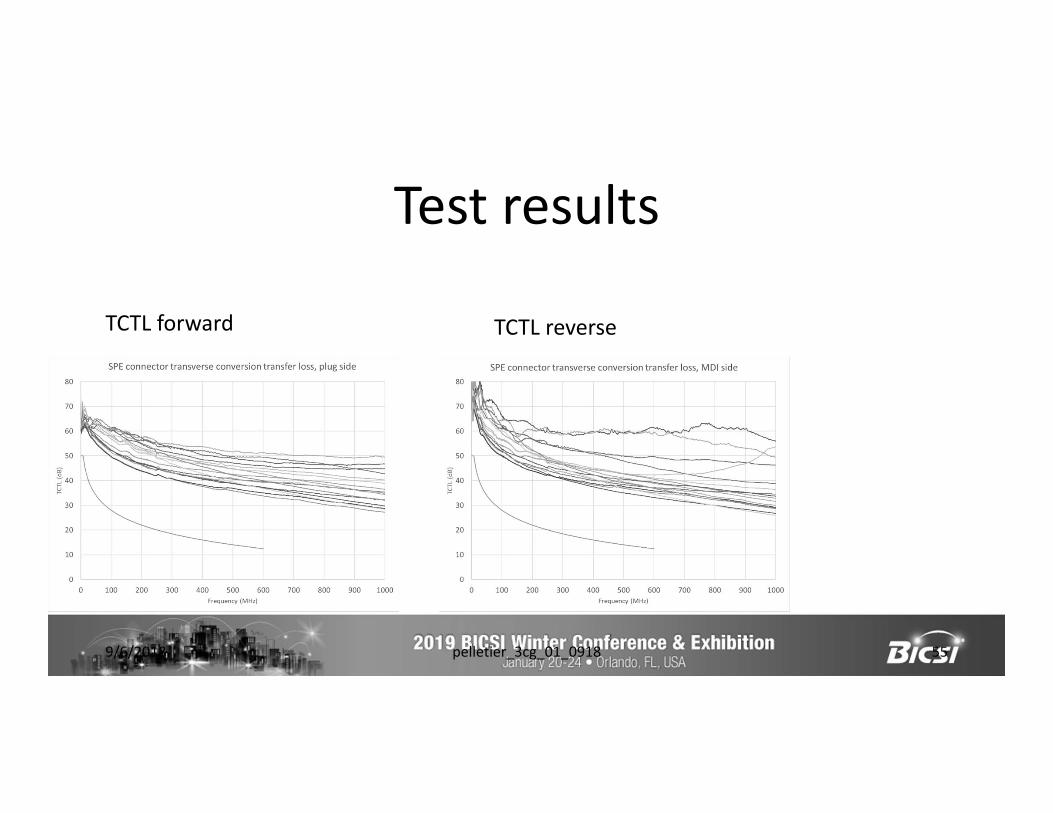
Test results
9/6/2018 pelletier_3cg_01_0918 55
TCTL forward TCTL reverse
Conclusion
• Two (2) different manufacturers made compliant copper LC connectors.• The IEC 63171-1 limits for IL, RL, TCL and TCTL are met when plugs and jacks from
the two (2) manufacturers are interchanged.
9/6/2018 pelletier_3cg_01_0918 56
Field testing – An important quality metric
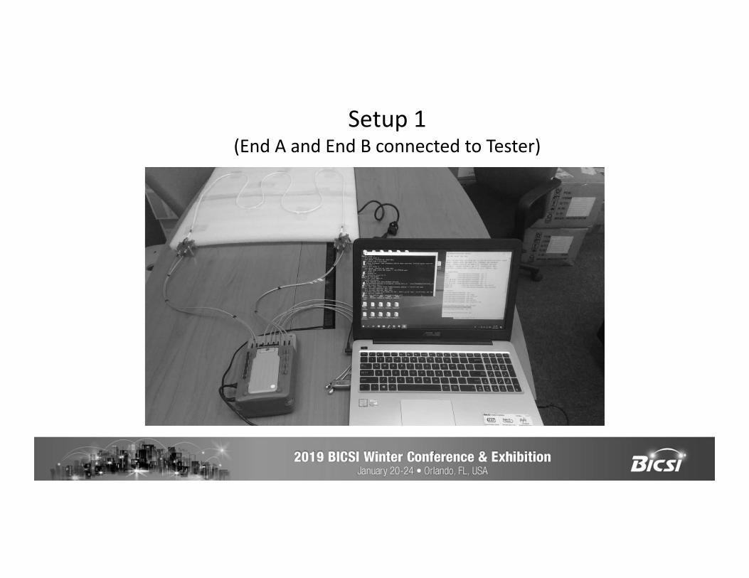
Setup 1 (End A and End B connected to Tester)
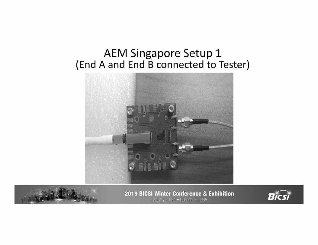
AEM Singapore Setup 1 (End A and End B connected to Tester)
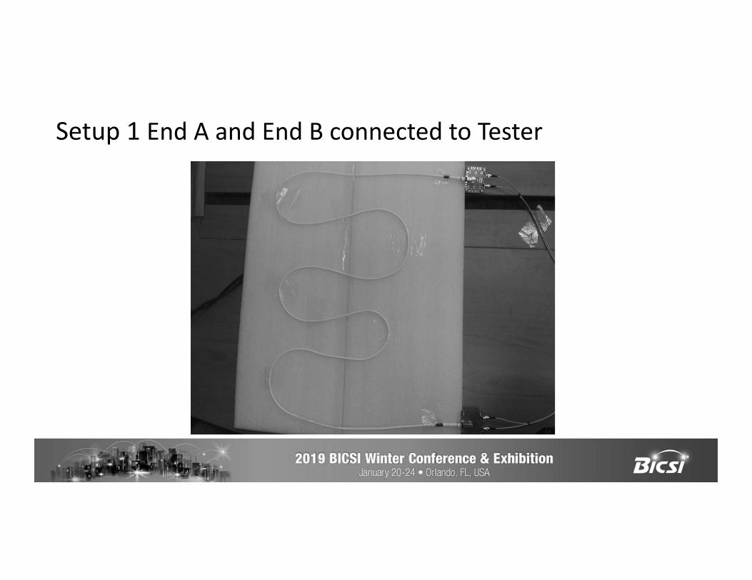
Setup 1 End A and End B connected to Tester

Return Loss (IL)
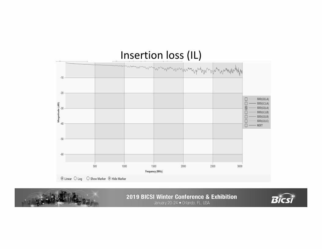
Insertion loss (IL)
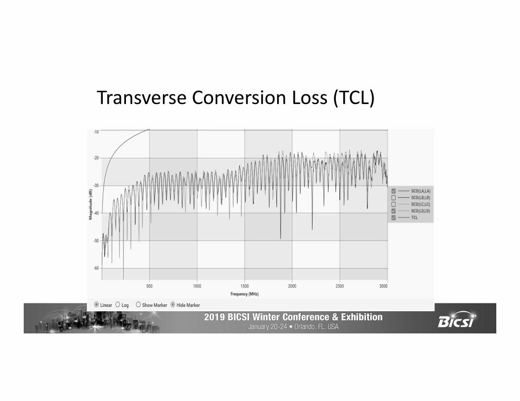
Transverse Conversion Loss (TCL)

Top Hurdles for IoT Deployment Accenture Healthcare Report 2017 Privacy concerns 55% Legacy systems and equipment 55% Security concerns 54%Technology immaturity 53%Lack of budget 53 %
IEEE
Security, standardization & connectivity are at the TOP of all the lists.

How can BICSI members help?
• BICSI members can help existing common 1-pair use cases to migrate to Single Pair Ethernet supported by generic structured cabling to improve relative costs, usability, maintenance, and operations
• Move to structured 1-pair generic cabling will enable existing and emerging IEEE 802.3 1-pair applications to be used for data and control networking, bringing extra security, reliability, and robustness to these existing 1-pair applications
• BICSI members understand IT networks and OT networks and can help bridge the gap between these networks
Conclusions and Take Away• Single pair Ethernet applications for communications and
power are happening now• ISO, IEC, TIA, and CENLEC cabling standards are following
suit with several projects• Need for low cost, high density infrastructure will lead to
widespread adoption and growth in the next 3 to 6 years• Need engagement from BICSI as a key stakeholder of the
single pair cabling/applications ecosystem
Thank You!