Embed Size (px)
Citation preview
Prepared by:
Genesis Oil & Gas Consultants Ltd 6 Albyn Place, Aberdeen, AB10 1YH
Tel. +44 (0) 1224 615100, Fax. +44 (0)1224 615111 www.genesisoilandgas.com
Technical Note EU ETS 2007 Support
Genesis Job Number J-70695/A
December 07
Genesis Oil & Gas Consultants Ltd Page 2 of 25 Date: Dec 07 File name: J70695-A-X-TN-001-B2.doc Revision: B2
CLIENT: DTI
PROJECT/JOB TITLE: EU ETS 2007 Support
DOCUMENT TYPE: Technical Note
DOCUMENT TITLE: Uncertainty Assessment of Quality Measurements in Relation to EU ETS Requirements – Guidance for Offshore Oil and Gas Production Facilities – Proposals for Flow Meter Uncertainty Values
GENESIS JOB NUMBER: J-70695/A
DOCUMENT NO./ FILE NAME: J70695-A-X-TN-001-B2.doc
B2 29/12/07 Issued for Client Comment JP IS B1 15/10/07 Issued for Client Comment JP IS
Rev Date Description Issued By Checked By
Approved By
Client Approval
DTI EU ETS 2007 Support
Proposals for Flow Meter Uncertainty Values
Genesis Oil & Gas Consultants Ltd Page 3 of 25 Date: Dec 07 File name: J70695-A-X-TN-001-B2.doc Revision: B2
Table of Contents
1 INTRODUCTION.................................................................................................4
2 SCOPE OF WORK..............................................................................................5
3 SUMMARY..........................................................................................................6
4 FLOW METER UNCERTAINTY DISCUSSION.................................................12 4.1 ROTOR METER...................................................................................................... 12 4.2 TURBINE FLOWMETER ........................................................................................... 12 4.3 BELLOWS FLOWMETER.......................................................................................... 12 4.4 ORIFICE FLOWMETER ............................................................................................ 13
4.4.1 Fuel Gas Service .....................................................................................................................14 4.4.2 Flare Gas Service....................................................................................................................14
4.5 VENTURI FLOW METERS........................................................................................ 14 4.5.1 Fuel Gas Service .....................................................................................................................15 4.5.2 Flare Gas Service....................................................................................................................16
4.6 V-CONE FLOW METER ........................................................................................... 16 4.6.1 Fuel Gas Service .....................................................................................................................17 4.6.2 Flare Gas Service....................................................................................................................17
4.7 ULTRASONIC FLOW METERS .................................................................................. 17 4.7.1 Fuel Gas Service .....................................................................................................................18 4.7.2 Flare Gas Service....................................................................................................................18
4.8 VORTEX FLOW METERS......................................................................................... 20 4.8.1 Fuel Gas Service .....................................................................................................................21 4.8.2 Flare Gas Service....................................................................................................................21
4.9 CORIOLIS FLOW METERS....................................................................................... 21 4.9.1 Fuel Gas Service .....................................................................................................................21 4.9.2 Flare Gas Service....................................................................................................................21
4.10 FLARE GAS DETERMINATION BY SUMMATION OF CONTRIBUTORY MEASUREMENTS ... 22 5 REFERENCES..................................................................................................24
DTI EU ETS 2007 Support
Proposals for Flow Meter Uncertainty Values
Genesis Oil & Gas Consultants Ltd Page 4 of 25 Date: Dec 07 File name: J70695-A-X-TN-001-B2.doc Revision: B2
1 INTRODUCTION This report has been commissioned by Department for Business, Enterprise & Regulatory Reform (BERR). As part of the EU Emissions Trading Scheme (ETS), operators are required to submit a monitoring plan to the regulatory authorities (HOLD) containing details of how certain sources of CO2 emissions will be determined. This needs to include an uncertainty analysis of the measurement system for each such source stream. The document Uncertainty Assessment of Quality Measurements in Relation to EU ETS Requirements – Guidance Note 1 (ref 1) contains guidance notes on practical ways to assess the uncertainties of flow meters and systems used for the measurement of fuels that are used as part of EU ETS monitoring. In particular it provides uncertainties of measurement for a number of flow meters commonly used for liquid and gas fuel measurement. The values stated can be used by operators in lieu of uncertainties determined from detailed uncertainty analysis, provided that the flow meter selection, installation and use is in accordance associated standards, codes of practice and manufacturers recommendations. Because of additional complexities associated with flow measurement on offshore production installations it was considered that specific guidance was needed for flow meters used offshore. This report contains discussions and proposals for uncertainties that can be used by operators for flow meters that are in common use for fuel gas and flare gas measurement on offshore installations. It should be noted that the uncertainties proposed are the uncertainties of the primary measurement units for each flow meter as set out in the document Uncertainty Assessment of Quality Measurements in Relation to EU ETS Requirements – Guidance Note 1 (ref 1). Operators should recognise the overall uncertainties in determining CO2 quantities which will take into account;
• the uncertainty of conversion from measured units to any other unit as necessary. This may include the uncertainty in pressure and temperature measurement, density determination, compressibility etc,
• the uncertainty in determining CO2 emissions.
DTI EU ETS 2007 Support
Proposals for Flow Meter Uncertainty Values
Genesis Oil & Gas Consultants Ltd Page 5 of 25 Date: Dec 07 File name: J70695-A-X-TN-001-B2.doc Revision: B2
2 SCOPE OF WORK The scope of work is the review of Appendix 1 of the document Uncertainty Assessment of Quality Measurements in Relation to EU ETS Requirements – Guidance Note 1 (ref 1) with respect to its applicability to offshore European continental shelf oil and gas production activities. In reviewing this appendix other parts of the document had to be referred to in order to better understand the content of Annex 1. This has given rise to comments on the content of these other parts which have been included within this report.

DTI EU ETS 2007 Support
Proposals for Flow Meter Uncertainty Values
Genesis Oil & Gas Consultants Ltd Page 6 of 25 Date: Dec 07 File name: J70695-A-X-TN-001-B2.doc Revision: B2
3 SUMMARY The following tables summarise the uncertainty recommendations and conditions discussed in Section 4 of this report. They are in a similar form to the tables in Annex 1 of Uncertainty Assessment of Quality Measurements in Relation to EU ETS Requirements – Guidance Note 1 (ref 1). Rotor Meter Medium: fuel gas Rotor flow meters are considered unsuitable for fuel gas measurement on offshore installations. Medium: flare gas Rotor flow meters are unsuitable for flare gas measurement. Turbine Meter Medium: fuel gas Turbine flow meters are considered unsuitable for fuel gas measurement on offshore installations. Medium: flare gas Turbine flow meters are unsuitable for flare gas measurement. Bellows Meter Medium: fuel gas Bellows flow meters are unsuitable for fuel gas measurement on offshore installations. Medium: flare gas Bellows flow meters are unsuitable for flare gas measurement.

DTI EU ETS 2007 Support
Proposals for Flow Meter Uncertainty Values
Genesis Oil & Gas Consultants Ltd Page 7 of 25 Date: Dec 07 File name: J70695-A-X-TN-001-B2.doc Revision: B2
Orifice Meter Medium: fuel gas Uncertainty: ±1.5% relative (mass flow rate) over a 2.8:1 turndown with a single differential pressure transmitters or 3.2:1 with two differential pressure transmitters. Conditions:
• beta ratio range of 0.1 to 0.75, • the use of an orifice plate carrier or orifice flanges installed to the
requirements of ISO 5167-2:2003, • measured or calculated density (from chromatograph analysis) to an
uncertainty of no greater than ±0.4% relative, • meter tube/pipe diameter uncertainty of no greater than ±0.4% relative • orifice place bore uncertainty of no greater than ±0.1% relative, • the use of correctly specified, installed and calibrated differential pressure
transmitter(s), • the use of a correctly specified, installed and calibrated line pressure
transmitter connected to the upstream differential pressure tapping, • the use of a correctly specified, installed and calibrated temperature
transmitter, • annual calibration of the differential pressure transmitter and line pressure
transmitter to a tolerance of ±0.25%, • annual calibration of the temperature transmitter to a tolerance of ±0.5 oC, • flow calculations performed in a modern DCS, without iteration and no meter
bore or orifice correction calculation but including a downstream to upstream temperature correction,
• inspection frequency for orifice plate, 2 yearly, • recalibration frequency for orifice plate, 5 yearly, • inspection and recalibration frequency for associated instruments, 1 yearly, • life expectancy 15 years.
Where the density is determined from periodic sampling the operator should calculate the uncertainty in the density value determined and used within the flow computing calculations. This should take into account;
• the uncertainty in the sample extraction, transportation and handling, • the uncertainty in any analysis technique or densitometer used, • the variance in composition between repeated the sampling.
Medium: flare gas Orifice flow meters are unsuitable for flare gas measurement.

DTI EU ETS 2007 Support
Proposals for Flow Meter Uncertainty Values
Genesis Oil & Gas Consultants Ltd Page 8 of 25 Date: Dec 07 File name: J70695-A-X-TN-001-B2.doc Revision: B2
Venturi Meter Medium: fuel gas Uncertainty: ±1.5% relative (mass flow rate) over a 2.8:1 turndown with a single differential pressure transmitters or 3.2:1 with two differential pressure transmitters. Conditions:
• beta ratio range of 0.4 to 0.75, • the use of a machined and calibrated venturi meter installed to the
requirements of ISO 5167-4 (ref 6), • measured or calculated density (from chromatograph analysis) to an
uncertainty of no greater than ±0.4% relative, • meter diameter uncertainty of ±0.4% relative • meter thought bore uncertainty of ±0.1% relative, • the use of correctly specified, installed and calibrated differential pressure
transmitter(s), • the use of a correctly specified, installed and calibrated line pressure
transmitter connected to the upstream differential pressure tapping, • the use of a correctly specified, installed and calibrated temperature
transmitter, • annual calibration of the differential pressure transmitter and line pressure
transmitter to a tolerance of ±0.25%, • annual calibration of the temperature transmitter to a tolerance of ±0.5 oC, • flow calculations performed within a modern DCS, without iteration and no
meter bore or orifice correction calculation but including a downstream to upstream temperature correction,
• inspection frequency for flow meter, 2 yearly, • recalibration frequency for flow meter, 5 yearly, • inspection and recalibration frequency for associated instruments, 1 yearly, • life expectancy 15 years.
Where the density is determined from periodic sampling the operator should calculate the uncertainty in the density value determined and used within the flow computing calculations. This should take into account;
• the uncertainty in the sample extraction, transportation and handling, • the uncertainty in any analysis technique or densitometer used, • the variance in composition between repeated the sampling.
Medium: flare gas Venturi flow meters are unsuitable for flare gas measurement.
DTI EU ETS 2007 Support
Proposals for Flow Meter Uncertainty Values
Genesis Oil & Gas Consultants Ltd Page 9 of 25 Date: Dec 07 File name: J70695-A-X-TN-001-B2.doc Revision: B2
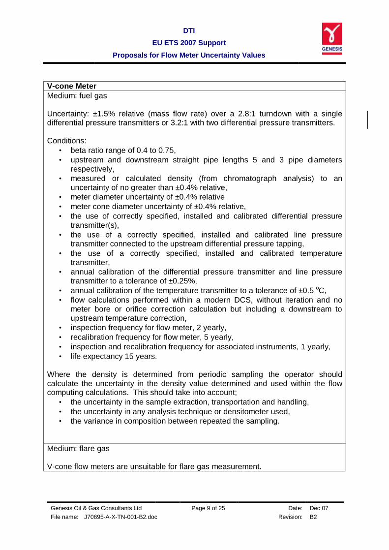
V-cone Meter Medium: fuel gas Uncertainty: ±1.5% relative (mass flow rate) over a 2.8:1 turndown with a single differential pressure transmitters or 3.2:1 with two differential pressure transmitters. Conditions:
• beta ratio range of 0.4 to 0.75, • upstream and downstream straight pipe lengths 5 and 3 pipe diameters
respectively, • measured or calculated density (from chromatograph analysis) to an
uncertainty of no greater than ±0.4% relative, • meter diameter uncertainty of ±0.4% relative • meter cone diameter uncertainty of ±0.4% relative, • the use of correctly specified, installed and calibrated differential pressure
transmitter(s), • the use of a correctly specified, installed and calibrated line pressure
transmitter connected to the upstream differential pressure tapping, • the use of a correctly specified, installed and calibrated temperature
transmitter, • annual calibration of the differential pressure transmitter and line pressure
transmitter to a tolerance of ±0.25%, • annual calibration of the temperature transmitter to a tolerance of ±0.5 oC, • flow calculations performed within a modern DCS, without iteration and no
meter bore or orifice correction calculation but including a downstream to upstream temperature correction,
• inspection frequency for flow meter, 2 yearly, • recalibration frequency for flow meter, 5 yearly, • inspection and recalibration frequency for associated instruments, 1 yearly, • life expectancy 15 years.
Where the density is determined from periodic sampling the operator should calculate the uncertainty in the density value determined and used within the flow computing calculations. This should take into account;
• the uncertainty in the sample extraction, transportation and handling, • the uncertainty in any analysis technique or densitometer used, • the variance in composition between repeated the sampling.
Medium: flare gas V-cone flow meters are unsuitable for flare gas measurement.
DTI EU ETS 2007 Support
Proposals for Flow Meter Uncertainty Values
Genesis Oil & Gas Consultants Ltd Page 10 of 25 Date: Dec 07 File name: J70695-A-X-TN-001-B2.doc Revision: B2
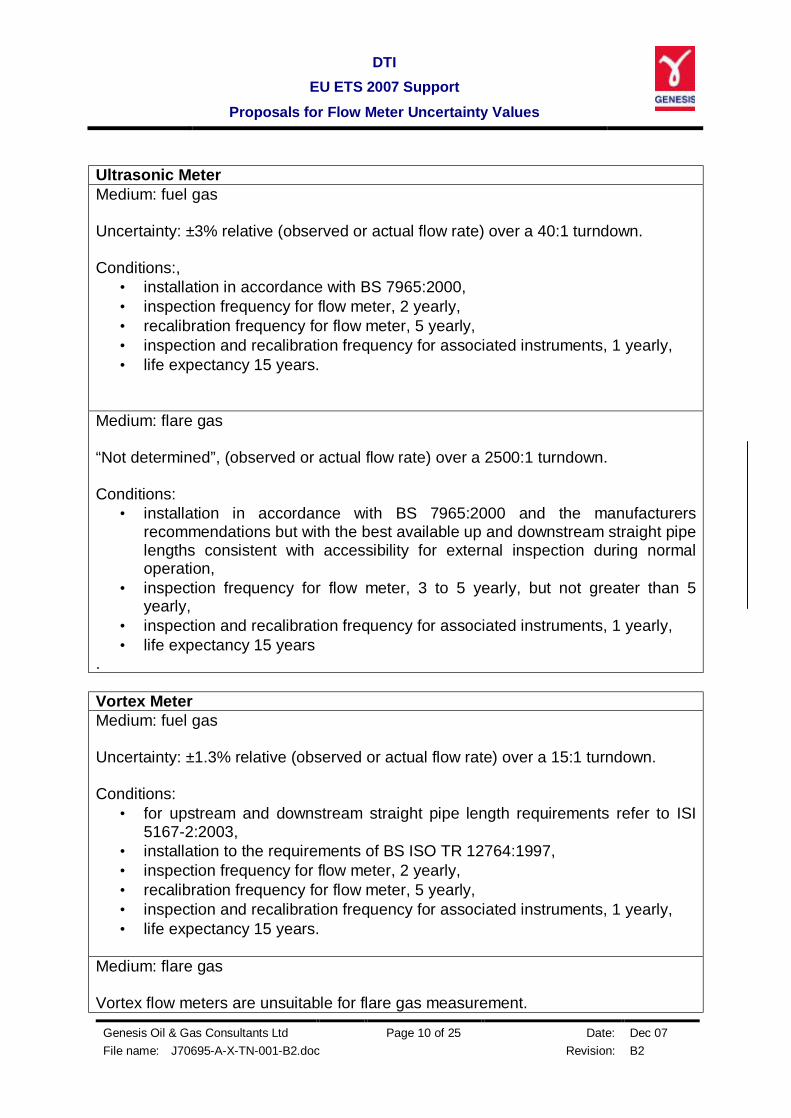
Ultrasonic Meter Medium: fuel gas Uncertainty: ±3% relative (observed or actual flow rate) over a 40:1 turndown. Conditions:,
• installation in accordance with BS 7965:2000, • inspection frequency for flow meter, 2 yearly, • recalibration frequency for flow meter, 5 yearly, • inspection and recalibration frequency for associated instruments, 1 yearly, • life expectancy 15 years.
Medium: flare gas “Not determined”, (observed or actual flow rate) over a 2500:1 turndown. Conditions:
• installation in accordance with BS 7965:2000 and the manufacturers recommendations but with the best available up and downstream straight pipe lengths consistent with accessibility for external inspection during normal operation,
• inspection frequency for flow meter, 3 to 5 yearly, but not greater than 5 yearly,
• inspection and recalibration frequency for associated instruments, 1 yearly, • life expectancy 15 years
. Vortex Meter Medium: fuel gas Uncertainty: ±1.3% relative (observed or actual flow rate) over a 15:1 turndown. Conditions:
• for upstream and downstream straight pipe length requirements refer to ISI 5167-2:2003,
• installation to the requirements of BS ISO TR 12764:1997, • inspection frequency for flow meter, 2 yearly, • recalibration frequency for flow meter, 5 yearly, • inspection and recalibration frequency for associated instruments, 1 yearly, • life expectancy 15 years.
Medium: flare gas Vortex flow meters are unsuitable for flare gas measurement.
DTI EU ETS 2007 Support
Proposals for Flow Meter Uncertainty Values
Genesis Oil & Gas Consultants Ltd Page 11 of 25 Date: Dec 07 File name: J70695-A-X-TN-001-B2.doc Revision: B2
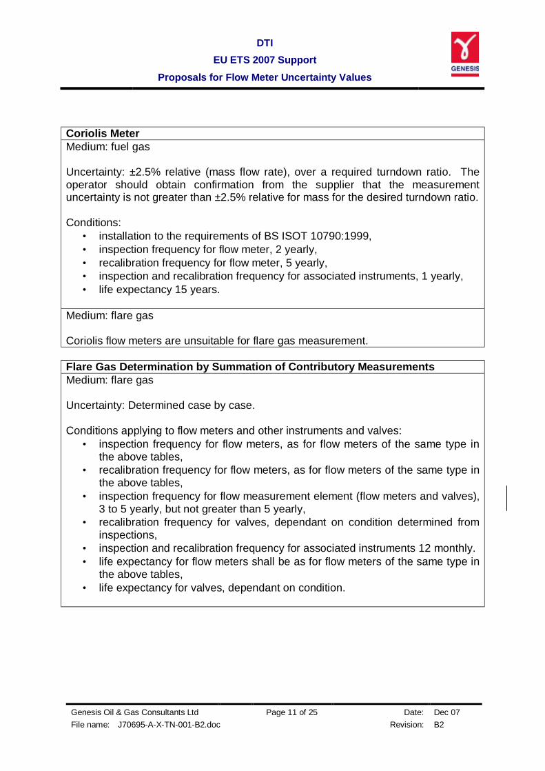
Coriolis Meter Medium: fuel gas Uncertainty: ±2.5% relative (mass flow rate), over a required turndown ratio. The operator should obtain confirmation from the supplier that the measurement uncertainty is not greater than ±2.5% relative for mass for the desired turndown ratio. Conditions:
• installation to the requirements of BS ISOT 10790:1999, • inspection frequency for flow meter, 2 yearly, • recalibration frequency for flow meter, 5 yearly, • inspection and recalibration frequency for associated instruments, 1 yearly, • life expectancy 15 years.
Medium: flare gas Coriolis flow meters are unsuitable for flare gas measurement. Flare Gas Determination by Summation of Contributory Measurements Medium: flare gas Uncertainty: Determined case by case. Conditions applying to flow meters and other instruments and valves:
• inspection frequency for flow meters, as for flow meters of the same type in the above tables,
• recalibration frequency for flow meters, as for flow meters of the same type in the above tables,
• inspection frequency for flow measurement element (flow meters and valves), 3 to 5 yearly, but not greater than 5 yearly,
• recalibration frequency for valves, dependant on condition determined from inspections,
• inspection and recalibration frequency for associated instruments 12 monthly. • life expectancy for flow meters shall be as for flow meters of the same type in
the above tables, • life expectancy for valves, dependant on condition.
DTI EU ETS 2007 Support
Proposals for Flow Meter Uncertainty Values
Genesis Oil & Gas Consultants Ltd Page 12 of 25 Date: Dec 07 File name: J70695-A-X-TN-001-B2.doc Revision: B2
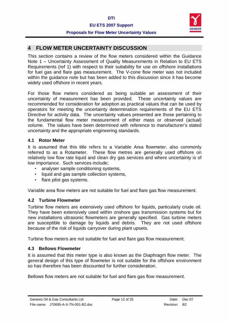
4 FLOW METER UNCERTAINTY DISCUSSION This section contains a review of the flow meters considered within the Guidance Note 1 – Uncertainty Assessment of Quality Measurements in Relation to EU ETS Requirements (ref 1) with respect to their suitability for use on offshore installations for fuel gas and flare gas measurement. The V-cone flow meter was not included within the guidance note but has been added to this discussion since it has become widely used offshore in recent years. For those flow meters considered as being suitable an assessment of their uncertainty of measurement has been provided. These uncertainty values are recommended for consideration for adoption as practical values that can be used by operators for meeting the uncertainty determination requirements of the EU ETS Directive for activity data. The uncertainty values presented are those pertaining to the fundamental flow meter measurement of either mass or observed (actual) volume. The values have been determined with reference to manufacturer’s stated uncertainty and the appropriate engineering standards.
4.1 Rotor Meter It is assumed that this title refers to a Variable Area flowmeter, also commonly referred to as a Rotameter. These flow metres are generally used offshore on relatively low flow rate liquid and clean dry gas services and where uncertainty is of low importance. Such services include;
• analyser sample conditioning systems, • liquid and gas sample collection systems, • flare pilot gas systems.
Variable area flow meters are not suitable for fuel and flare gas flow measurement.
4.2 Turbine Flowmeter Turbine flow meters are extensively used offshore for liquids, particularly crude oil. They have been extensively used within onshore gas transmission systems but for new installations ultrasonic flowmeters are generally specified. Gas turbine meters are susceptible to damage by liquids and debris. They are not used offshore because of the risk of liquids carryover during plant upsets. Turbine flow meters are not suitable for fuel and flare gas flow measurement.
4.3 Bellows Flowmeter It is assumed that this meter type is also known as the Diaphragm flow meter. The general design of this type of flowmeter is not suitable for the offshore environment so has therefore has been discounted for further consideration. Bellows flow meters are not suitable for fuel and flare gas flow measurement.

DTI EU ETS 2007 Support
Proposals for Flow Meter Uncertainty Values
Genesis Oil & Gas Consultants Ltd Page 13 of 25 Date: Dec 07 File name: J70695-A-X-TN-001-B2.doc Revision: B2
4.4 Orifice Flowmeter Orifice flow meters have been extensively used offshore and in the past the most were the most popular meter type for both liquid and gas. Other meter types using newer technology, such as ultrasonic and coriolis meters are now widely specified in preference to orifice meter types. Referring to ISO 5167-2 (ref 5), typical upstream and downstream straight pipe lengths are 42 and 7 pipe diameters respectively. However these can be up to 75 and 8 pipe diameters respectively. The standard allows for the straight lengths requirements to be halved at the expense of accepting a doubling of the uncertainty in the discharge coefficient. Orifice flow meters are mass meters but require a density value as part of the flow rate calculation. Density can be measured using a densitometer, calculated from an on-line chromatograph analysis or a fixed value could be used determined from periodic spot sampling. The uncertainty in measured density, allowing for densitometer calibration drift and for calculated density, from on-line chromatograph determined composition would typically be no greater than ±0.4% relative. This includes pressure and temperature measurement uncertainty. The density uncertainty using a fixed value would depend on the variance in actual gas density as well as the uncertainty of the determination method, which would need to be determined on a case by case basis. The mass flow uncertainty of a fiscal orifice meter in not greater than ±1.0%. Such a system would use either a measured density or a calculated density from an on-line chromatograph. Constraints in orifice beta ratio and secondary instrumentation would be required to achieve this. The mass flow uncertainty of an orifice meter system installed in accordance with ISO 5167-2 (ref 5) and using either a measured density or calculated from an on-line chromatograph but without the beta ratio and secondary equipment selection constraints of a fiscal system has been calculated to be not greater than ±1.5%, for a turndown ratio of 2.8:1 using a single differential pressure transmitter or 3.2:1 using two differential pressure transmitters appropriately ranged. This is based on the flowing requirements;
• beta ratio range of 0.1 to 0.75, • the use of an orifice plate carrier or orifice flanges installed to the
requirements of ISO 5167-2 (ref 5), • measured or calculated density (from chromatograph analysis) to an
uncertainty of no greater than ±0.4% relative, • meter tube/pipe diameter uncertainty of no greater than ±0.4% relative • orifice place bore uncertainty of no greater than ±0.1% relative, • the use of correctly specified, installed and calibrated differential pressure
transmitter(s), • the use of a correctly specified, installed and calibrated line pressure
transmitter connected to the upstream differential pressure tapping, • the use of a correctly specified, installed and calibrated temperature
transmitter,

DTI EU ETS 2007 Support
Proposals for Flow Meter Uncertainty Values
Genesis Oil & Gas Consultants Ltd Page 14 of 25 Date: Dec 07 File name: J70695-A-X-TN-001-B2.doc Revision: B2
• annual calibration of the differential pressure transmitter and line pressure transmitter to a tolerance of ±0.25%,
• annual calibration of the temperature transmitter to a tolerance of ±0.5 oC, • flow calculations performed in a modern DCS, without iteration and no meter
bore or orifice correction calculation but including a downstream to upstream temperature correction.
Where the density is determined from periodic sampling the operator should calculate the uncertainty in the density value determined and used within the flow computing calculations. This should take into account;
• the uncertainty in the sample extraction, transportation and handling, • the uncertainty in any analysis technique or densitometer used, • the variance in composition between repeated the sampling.
The operator can then calculate the mass flow rate uncertainty from the equation;
%25.049.1 22ρEEm ×+= relative
where Eρ is the density uncertainty as a percent of reading. 4.4.1 Fuel Gas Service Orifice flow meters are considered to be suitable for fuel gas service. Provided that the installation conforms to the requirements stated in 4.4 above the gas density is measured or calculated from analysis an uncertainty of ±1.5% can be expected over a 2.8:1 turndown or 3.2:1 with two differential pressure transmitters. It is recommended that operators are permitted to use ±1.5% relative for the mass flow rate uncertainty for orifice flow meters used for fuel gas service when installed in accordance of the requirements of ISO 5167-2 (ref 5), the requirements stated in 4.4 above and the density is determined by densitometer measurements or calculated from chromatograph analysis of the fuel gas. 4.4.2 Flare Gas Service Orifice flow meters are unsuitable for flare gas measurement due to;
• limited turndown range, • relatively high pressure loss at high flow rates, • very long straight pipe length requirements, • potential for blockage due to hydrates.
4.5 Venturi Flow Meters Venturi flow meters have been used offshore for the both liquid and gas measurement. Being differential pressure type mass flow meters their installation and secondary instrument requirements are similar to those stated for orifice flow meters in 4.4 above except that they require shorter straight pipe lengths. Referring to ISO 5167-4 (ref 6), typical upstream and downstream straight lengths are 26 and 7 pipe diameters respectively. However these can be up to 80 and 8 pipe diameters respectively. Providing the meter has been calibrated on a similar fluid to that which
DTI EU ETS 2007 Support
Proposals for Flow Meter Uncertainty Values
Genesis Oil & Gas Consultants Ltd Page 15 of 25 Date: Dec 07 File name: J70695-A-X-TN-001-B2.doc Revision: B2
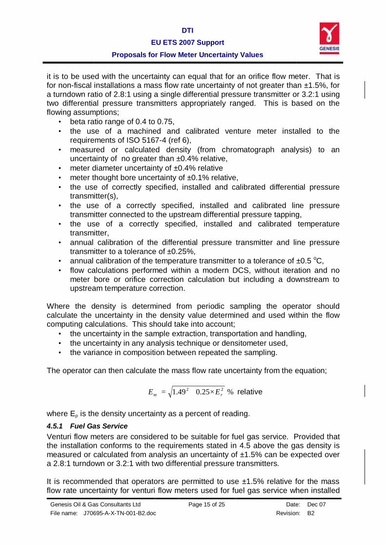
it is to be used with the uncertainty can equal that for an orifice flow meter. That is for non-fiscal installations a mass flow rate uncertainty of not greater than ±1.5%, for a turndown ratio of 2.8:1 using a single differential pressure transmitter or 3.2:1 using two differential pressure transmitters appropriately ranged. This is based on the flowing assumptions;
• beta ratio range of 0.4 to 0.75, • the use of a machined and calibrated venture meter installed to the
requirements of ISO 5167-4 (ref 6), • measured or calculated density (from chromatograph analysis) to an
uncertainty of no greater than ±0.4% relative, • meter diameter uncertainty of ±0.4% relative • meter thought bore uncertainty of ±0.1% relative, • the use of correctly specified, installed and calibrated differential pressure
transmitter(s), • the use of a correctly specified, installed and calibrated line pressure
transmitter connected to the upstream differential pressure tapping, • the use of a correctly specified, installed and calibrated temperature
transmitter, • annual calibration of the differential pressure transmitter and line pressure
transmitter to a tolerance of ±0.25%, • annual calibration of the temperature transmitter to a tolerance of ±0.5 oC, • flow calculations performed within a modern DCS, without iteration and no
meter bore or orifice correction calculation but including a downstream to upstream temperature correction.
Where the density is determined from periodic sampling the operator should calculate the uncertainty in the density value determined and used within the flow computing calculations. This should take into account;
• the uncertainty in the sample extraction, transportation and handling, • the uncertainty in any analysis technique or densitometer used, • the variance in composition between repeated the sampling.
The operator can then calculate the mass flow rate uncertainty from the equation;
%25.049.1 22ρEEm ×+= relative
where Eρ is the density uncertainty as a percent of reading. 4.5.1 Fuel Gas Service Venturi flow meters are considered to be suitable for fuel gas service. Provided that the installation conforms to the requirements stated in 4.5 above the gas density is measured or calculated from analysis an uncertainty of ±1.5% can be expected over a 2.8:1 turndown or 3.2:1 with two differential pressure transmitters. It is recommended that operators are permitted to use ±1.5% relative for the mass flow rate uncertainty for venturi flow meters used for fuel gas service when installed
DTI EU ETS 2007 Support
Proposals for Flow Meter Uncertainty Values
Genesis Oil & Gas Consultants Ltd Page 16 of 25 Date: Dec 07 File name: J70695-A-X-TN-001-B2.doc Revision: B2
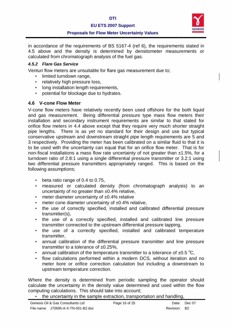
in accordance of the requirements of BS 5167-4 (ref 6), the requirements stated in 4.5 above and the density is determined by densitometer measurements or calculated from chromatograph analysis of the fuel gas. 4.5.2 Flare Gas Service Venturi flow meters are unsuitable for flare gas measurement due to;
• limited turndown range, • relatively high pressure loss, • long installation length requirements, • potential for blockage due to hydrates.
4.6 V-cone Flow Meter V-cone flow meters have relatively recently been used offshore for the both liquid and gas measurement. Being differential pressure type mass flow meters their installation and secondary instrument requirements are similar to that stated for orifice flow meters in 4.4 above except that they require very much shorter straight pipe lengths. There is as yet no standard for their design and use but typical conservative upstream and downstream straight pipe length requirements are 5 and 3 respectively. Providing the meter has been calibrated on a similar fluid to that it is to be used with the uncertainty can equal that for an orifice flow meter. That is for non-fiscal installations a mass flow rate uncertainty of not greater than ±1.5%, for a turndown ratio of 2.8:1 using a single differential pressure transmitter or 3.2:1 using two differential pressure transmitters appropriately ranged. This is based on the following assumptions;
• beta ratio range of 0.4 to 0.75, • measured or calculated density (from chromatograph analysis) to an
uncertainty of no greater than ±0.4% relative, • meter diameter uncertainty of ±0.4% relative • meter cone diameter uncertainty of ±0.4% relative, • the use of correctly specified, installed and calibrated differential pressure
transmitter(s), • the use of a correctly specified, installed and calibrated line pressure
transmitter connected to the upstream differential pressure tapping, • the use of a correctly specified, installed and calibrated temperature
transmitter, • annual calibration of the differential pressure transmitter and line pressure
transmitter to a tolerance of ±0.25%, • annual calibration of the temperature transmitter to a tolerance of ±0.5 oC, • flow calculations performed within a modern DCS, without iteration and no
meter bore or orifice correction calculation but including a downstream to upstream temperature correction.
Where the density is determined from periodic sampling the operator should calculate the uncertainty in the density value determined and used within the flow computing calculations. This should take into account;
• the uncertainty in the sample extraction, transportation and handling,

DTI EU ETS 2007 Support
Proposals for Flow Meter Uncertainty Values
Genesis Oil & Gas Consultants Ltd Page 17 of 25 Date: Dec 07 File name: J70695-A-X-TN-001-B2.doc Revision: B2
• the uncertainty in any analysis technique or densitometer used, • the variance in composition between repeated the sampling.
The operator could then calculate the mass flow rate uncertainty from the equation;
%25.049.1 22ρEEm ×+= relative
where Eρ is the density uncertainty as a percent of reading. 4.6.1 Fuel Gas Service V-cone flow meters are considered to be suitable for fuel gas service. Provided that the installation conforms to the requirements stated in 4.6 above the gas density is measured or calculated from analysis an uncertainty of ±1.5% can be expected over a 2.8:1 turndown or 3.2:1 with two differential pressure transmitters. It is recommended that operators are permitted to use ±1.5% relative for the mass flow rate uncertainty for v-cone flow meters used for fuel gas service when installed in accordance of the requirements of the manufacturer, the requirements stated in 4.6 above and the density is determined by densitometer measurements or calculated from chromatograph analysis of the fuel gas 4.6.2 Flare Gas Service V-cone flow meters are unsuitable for flare gas measurement due to;
• limited turndown range, • relatively high pressure loss, • potential for blockage due to hydrates.
4.7 Ultrasonic Flow Meters Ultrasonic flow meters are extensively used offshore. Because of their large turndown, negligible pressure loss and relatively short up and downstream straight pipe length requirements they have become very popular. Referring to BS 7965 (ref 7), Table 2, upstream and downstream straight pipe lengths requirements are a function of the number of ultrasonic paths. These are;
• ≥4 path meters require 10 upstream and 3 downstream straight pipe diameters,
• ≥2 path meters require 50 upstream and 5 downstream straight pipe diameters,
• ≥1 path meters require 50 upstream and 5 downstream straight pipe diameters.
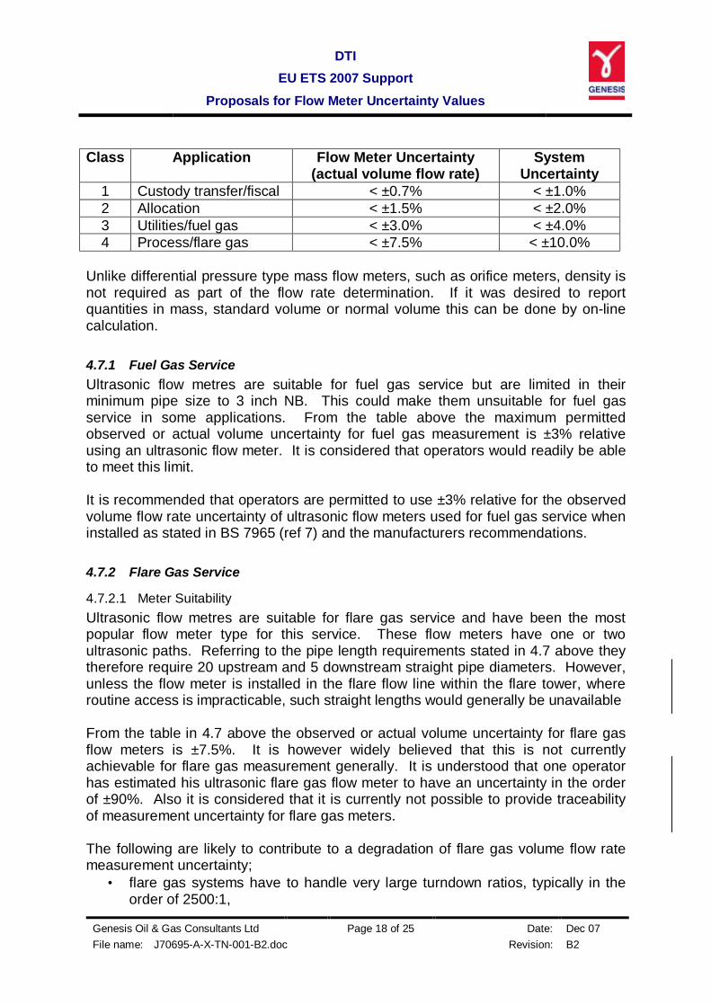
• The 1 and 2 path cases can be reduced to 10 upstream diameters with the use of a flow conditioner, but it should be noted this could not be used in a flare gas pipeline. Ultrasonic flow meters are volume meters. BS 7965 (ref 7) classifies ultrasonic flow meters according to their duty. An extract from the classification table, Table 1 in the standard is as follows;
DTI EU ETS 2007 Support
Proposals for Flow Meter Uncertainty Values
Genesis Oil & Gas Consultants Ltd Page 18 of 25 Date: Dec 07 File name: J70695-A-X-TN-001-B2.doc Revision: B2
Class Application Flow Meter Uncertainty
(actual volume flow rate) System
Uncertainty 1 Custody transfer/fiscal < ±0.7% < ±1.0% 2 Allocation < ±1.5% < ±2.0% 3 Utilities/fuel gas < ±3.0% < ±4.0% 4 Process/flare gas < ±7.5% < ±10.0%
Unlike differential pressure type mass flow meters, such as orifice meters, density is not required as part of the flow rate determination. If it was desired to report quantities in mass, standard volume or normal volume this can be done by on-line calculation. 4.7.1 Fuel Gas Service Ultrasonic flow metres are suitable for fuel gas service but are limited in their minimum pipe size to 3 inch NB. This could make them unsuitable for fuel gas service in some applications. From the table above the maximum permitted observed or actual volume uncertainty for fuel gas measurement is ±3% relative using an ultrasonic flow meter. It is considered that operators would readily be able to meet this limit. It is recommended that operators are permitted to use ±3% relative for the observed volume flow rate uncertainty of ultrasonic flow meters used for fuel gas service when installed as stated in BS 7965 (ref 7) and the manufacturers recommendations. 4.7.2 Flare Gas Service
4.7.2.1 Meter Suitability Ultrasonic flow metres are suitable for flare gas service and have been the most popular flow meter type for this service. These flow meters have one or two ultrasonic paths. Referring to the pipe length requirements stated in 4.7 above they therefore require 20 upstream and 5 downstream straight pipe diameters. However, unless the flow meter is installed in the flare flow line within the flare tower, where routine access is impracticable, such straight lengths would generally be unavailable From the table in 4.7 above the observed or actual volume uncertainty for flare gas flow meters is ±7.5%. It is however widely believed that this is not currently achievable for flare gas measurement generally. It is understood that one operator has estimated his ultrasonic flare gas flow meter to have an uncertainty in the order of ±90%. Also it is considered that it is currently not possible to provide traceability of measurement uncertainty for flare gas meters. The following are likely to contribute to a degradation of flare gas volume flow rate measurement uncertainty;
• flare gas systems have to handle very large turndown ratios, typically in the order of 2500:1,
DTI EU ETS 2007 Support
Proposals for Flow Meter Uncertainty Values
Genesis Oil & Gas Consultants Ltd Page 19 of 25 Date: Dec 07 File name: J70695-A-X-TN-001-B2.doc Revision: B2
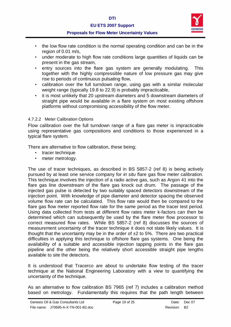
• the low flow rate condition is the normal operating condition and can be in the region of 0.01 m/s,
• under moderate to high flow rate conditions large quantities of liquids can be present in the gas stream,
• entry sources into the flare gas system are generally modulating. This together with the highly compressible nature of low pressure gas may give rise to periods of continuous pulsating flow,
• calibration over the full turndown range, using gas with a similar molecular weight range (typically 19.8 to 22.9) is probably impracticable,
• it is most unlikely that 20 upstream diameters and 5 downstream diameters of straight pipe would be available in a flare system on most existing offshore platforms without compromising accessibility of the flow meter.
4.7.2.2 Meter Calibration Options Flow calibration over the full turndown range of a flare gas meter is impracticable using representative gas compositions and conditions to those experienced in a typical flare system. There are alternative to flow calibration, these being;
• tracer technique • meter metrology.
The use of tracer techniques, as described in BS 5857-2 (ref 8) is being actively pursued by at least one service company for in situ flare gas flow meter calibration. This technique involves the injection of a radio active gas, such as Argon 41 into the flare gas line downstream of the flare gas knock out drum. The passage of the injected gas pulse is detected by two suitably spaced detectors downstream of the injection point. With knowledge of pipe diameter and detector spacing the observed volume flow rate can be calculated. This flow rate would then be compared to the flare gas flow meter reported flow rate for the same period as the tracer test period. Using data collected from tests at different flow rates meter k-factors can then be determined which can subsequently be used by the flare meter flow processor to correct measured flow rates. While BS 5857-2 (ref 8) discusses the sources of measurement uncertainty of the tracer technique it does not state likely values. It is thought that the uncertainty may be in the order of ±2 to 5%. There are two practical difficulties in applying this technique to offshore flare gas systems. One being the availability of a suitable and accessible injection tapping points in the flare gas pipeline and the other being the relatively short accessible straight pipe lengths available to site the detectors. It is understood that Tracerco are about to undertake flow testing of the tracer technique at the National Engineering Laboratory with a view to quantifying the uncertainty of the technique. As an alternative to flow calibration BS 7965 (ref 7) includes a calibration method based on metrology. Fundamentally this requires that the path length between

DTI EU ETS 2007 Support
Proposals for Flow Meter Uncertainty Values
Genesis Oil & Gas Consultants Ltd Page 20 of 25 Date: Dec 07 File name: J70695-A-X-TN-001-B2.doc Revision: B2
transducer pairs is accurately measured. For flare gas flow meters this would prove difficult in practice due to access constraints. However external measurements can be used to determine path lengths, albeit to a reduced uncertainty compared to direct measurement. This method does not however take account of possible damage to transducer probes that might affect the transducer spacing. A further alternative to flow calibration is the removal of the transducer probes and inserting them into a jig where the distance between the transducers is known from previous measurement. The flow meters flow computer is then be used to determine the flight time between the transducers and an offline calculation is used to calculate the transducer spacing to verify the accuracy of the flow meters measurement. Given the above considerations it is apparent that it would be inappropriate to specify an uncertainty value that could be used by operators for flare gas flow meters at this time. Moreover, it would also be unreasonable to expect operators to be able to determine the uncertainty of their flare gas flow meters. It is recommended that until such time that sufficient information is available to allow a reliable flare gas flow meter uncertainty to be determined for correctly installed systems operators should be permitted to use an uncertainty value of ±12.5% relative for volume flow rate. Following discussion with interested parties it is recommended that a pragmatic approach is taken where by a ultrasonic flare gas meter installation would be considered acceptable for the purposes of meeting the EU ETS requirements provided that;
• where there is insufficient straight pipe lengths available then the meter should be installed with best endeavours to maximise straight lengths, with due regard to providing access during normal operations,
• secondary instrumentation of appropriate design is installed where practicable to permit the flow controller/computer to calculate mass and standard volume flow rates from observed volume flow rate measurements.
4.8 Vortex Flow Meters Vortex flow meters are observed or actual volume flow meters. Although vortex flow meters are not in common use offshore they have been successfully used. BS ISO TR 12764 (ref 9) states that straight upstream and downstream pipe lengths are required in order to obtain the specified accuracy of the flow meter. The technical report however does not specify the required straight lengths or the flow meter accuracy. Typically the pipe lengths specified for orifice plate flow meters in ISO 5167-2 (ref 5) are used. That being about 42 upstream diameters and 7 downstream diameters of straight pipe. BS 7405 (ref 1) states the accuracy and repeatability for a calibrated vortex flow meter on a gas services would typically be ±1.25% and ±0.15% to 0.25% respectively. Combining these values gives a worst case volume measurement uncertainty of ±1.27% relative. The turndown ratio of vortex meters is up to about 15:1.
DTI EU ETS 2007 Support
Proposals for Flow Meter Uncertainty Values
Genesis Oil & Gas Consultants Ltd Page 21 of 25 Date: Dec 07 File name: J70695-A-X-TN-001-B2.doc Revision: B2
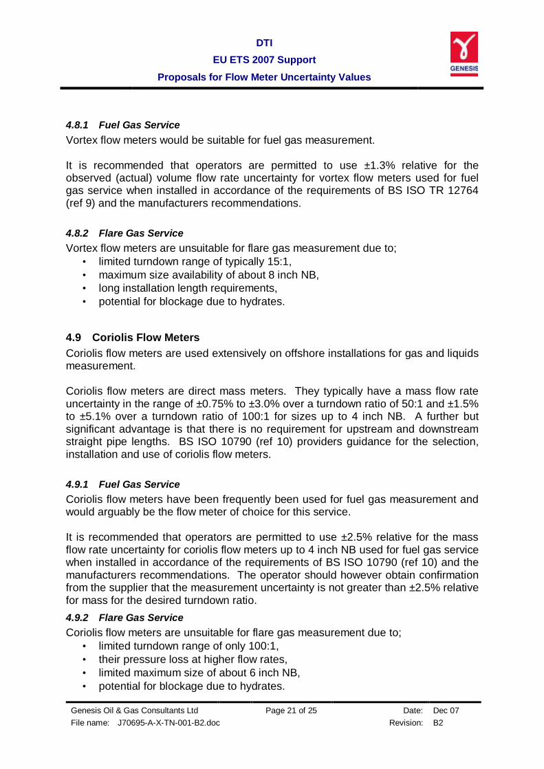
4.8.1 Fuel Gas Service Vortex flow meters would be suitable for fuel gas measurement. It is recommended that operators are permitted to use ±1.3% relative for the observed (actual) volume flow rate uncertainty for vortex flow meters used for fuel gas service when installed in accordance of the requirements of BS ISO TR 12764 (ref 9) and the manufacturers recommendations. 4.8.2 Flare Gas Service Vortex flow meters are unsuitable for flare gas measurement due to;
• limited turndown range of typically 15:1, • maximum size availability of about 8 inch NB, • long installation length requirements, • potential for blockage due to hydrates.
4.9 Coriolis Flow Meters Coriolis flow meters are used extensively on offshore installations for gas and liquids measurement. Coriolis flow meters are direct mass meters. They typically have a mass flow rate uncertainty in the range of ±0.75% to ±3.0% over a turndown ratio of 50:1 and ±1.5% to ±5.1% over a turndown ratio of 100:1 for sizes up to 4 inch NB. A further but significant advantage is that there is no requirement for upstream and downstream straight pipe lengths. BS ISO 10790 (ref 10) providers guidance for the selection, installation and use of coriolis flow meters. 4.9.1 Fuel Gas Service Coriolis flow meters have been frequently been used for fuel gas measurement and would arguably be the flow meter of choice for this service. It is recommended that operators are permitted to use ±2.5% relative for the mass flow rate uncertainty for coriolis flow meters up to 4 inch NB used for fuel gas service when installed in accordance of the requirements of BS ISO 10790 (ref 10) and the manufacturers recommendations. The operator should however obtain confirmation from the supplier that the measurement uncertainty is not greater than ±2.5% relative for mass for the desired turndown ratio. 4.9.2 Flare Gas Service Coriolis flow meters are unsuitable for flare gas measurement due to;
• limited turndown range of only 100:1, • their pressure loss at higher flow rates, • limited maximum size of about 6 inch NB, • potential for blockage due to hydrates.

DTI EU ETS 2007 Support
Proposals for Flow Meter Uncertainty Values
Genesis Oil & Gas Consultants Ltd Page 22 of 25 Date: Dec 07 File name: J70695-A-X-TN-001-B2.doc Revision: B2
4.10 Flare Gas Determination by Summation of Contributory Measurements An alternative to direct measurement of flare gas flow is to measure or otherwise determine all contributory flows into the flare gas system. Ideally this scheme would require a flow meter installed in all potentially flowing connections to the flare gas system. The flare gas flow quantities would then simply be the summation of all measurements integrated over a suitable time interval. In practice however it is highly unlikely that any UK continental shelf production installation would have such flow meters. Retrofitting of flow meters for this scheme would not only be impracticable in many instances but also prohibitively expensive. There are typically four types of entry flows into the flare system, they are;
• purge flows, • controlled flows, • relief flows • blow down flows
Purge flows are relatively constant small flow rate entries. These frequently have a flow meter installed, albeit a high uncertainty type such as a variable area meter. Provided that the flow rates are low the high measurement uncertainty or the uncertainty in estimation of flow rate would not have a great impact on the uncertainty of the overall flare gas flow determination. Controlled flows are those resulting from processes such as back pressure control of separators and blanket gas pressure control. These flows can vary due to production rate changes, equipment operating limitations and outages. Where no flow meter exists the flow rate can be determined from control valve opening position, corrected for upstream and temperature measurement. It can generally be assumed that control valves routed to the flare system will operate choked, and that back pressure effects are negligible. Relief flows emanate from abnormally high pressures, resulting in pressure relief vales lifting. The quantity of the relieved flow could be estimated from sources such as historic pressure and temperature measurement records. Clearly the uncertainty in the estimate may be quite large, however provided that the occurrence is infrequent the impact on the flare quantity determination uncertainty would be low when taken over a long period. Blow down normally occurs when a part or all of the process systems are shut down in an emergency situation. Quantities entering the flare system can be quite accurately determined using a process model from knowledge of vessel volumes, liquid contents levels, pressures and temperatures. Because of the diversity of production platform flare gas system designs and wide range of flared quantities the flare gas quantity uncertainty would need to be
DTI EU ETS 2007 Support
Proposals for Flow Meter Uncertainty Values
Genesis Oil & Gas Consultants Ltd Page 23 of 25 Date: Dec 07 File name: J70695-A-X-TN-001-B2.doc Revision: B2
determined case by case. Indeed in doing so the requirement for additional instrumentation may become apparent in order that acceptable flare gas determination uncertainties can be achieved.

DTI EU ETS 2007 Support
Proposals for Flow Meter Uncertainty Values
Genesis Oil & Gas Consultants Ltd Page 24 of 25 Date: Dec 07 File name: J70695-A-X-TN-001-B2.doc Revision: B2
5 REFERENCES
1. Uncertainty Assessment of Quality Measurements in Relation to EU ETS Requirements – Guidance Note 1, Emissions Trading Technical Support Group (ETSG).
2. BS 7405:1991, Selection and Application of Flowmeters for the Measurement of Fluid Flow in Closed Conduits, British Standards Institute March 2000.
3. BS 7835:1995 ISO:1993, Specification for Turbine Meters Used for the Measurement of Gas Flow in Closed Conduits, British Standards Institute 1999.
4. ISO 5167-1:2003, Measurement of Fluid Flow by Means of Pressure Differential Devices Inserted in Circular-cross Sectioned Conduits Running Full – Part 1 General Principles and Requirements, International Standards Institute, 2003.
5. ISO 5167-2:2003, Measurement of Fluid Flow by Means of Pressure Differential Devices Inserted in Circular-cross Sectioned Conduits Running Full – Part 2 Orifice Plates, International Standards Institute, 2003.
6. ISO 5167-4:2003, Measurement of Fluid Flow by Means of Pressure Differential Devices Inserted in Circular-cross Sectioned Conduits Running Full – Part 2 Venturi Tubes International Standards Institute, 2003.
7. BS 7965:2000, The Selection, Installation, Operation and Calibration of Diagonal Path Ultrasonic Flow Meters for Industrial Gas Applications, British Standards Institute, April 2000.
8. BS 5857-2.4:1980, ISO 4053-IV:1978, Methods of Measurement of Fluid Flow in Closed Conduits, Using Tracers – Part 2 Measurement of Gas Flow – Section 2.4 Transit Time Method Using Radioactive Tracers, British Standards Institute 31 March 1980.
9. BS ISO TR 12764:1997, Measurement of Fluid Flow in Closed Conduits - Flowrate Measurement by Means of Vortex Shedding Flowmeters Inserted in Circular Cross-section Conduits Running Full, British Standards Institute, April 1999.
DTI EU ETS 2007 Support
Proposals for Flow Meter Uncertainty Values
Genesis Oil & Gas Consultants Ltd Page 25 of 25 Date: Dec 07 File name: J70695-A-X-TN-001-B2.doc Revision: B2
10. BS ISO 10790:1999, Measurement of Fluid Flow in Closed Conduits- Guidance to the Selection, Installation and Use of Coriolis Meters (Mass flow, Density and Volume Flow Measurements), British Standards Institute, 15 July 1999