Embed Size (px)
Citation preview

Geo-Location of RF Emitters
Final Proposal
Sponsor: Michigan State University ECE Department
Facilitator: Dr. Jian Ren
Executive Summary
The ability to accurately detect the location of radio signals provides a wide variety of uses
ranging from determining the location of a distress signal from a party or individual in need of
help to locating an interfering signal that is jamming communications. This project focuses on
software defined radio technology to receive and process an RF signal to ultimately calculate
position and angle of arrival of emitting radio signal. Using this method to sample from multiple
locations we will be able to paint a picture of the location of the radio signal.
Design Team 2
Joe Godby | Justin Mascotto | Matthew Roach
Viktor Simovski | Kenneth Wilkins

2
Table of Contents
Contents Table of Contents .......................................................................................................................................... 2
1. Introduction .............................................................................................................................................. 3
2. Background ............................................................................................................................................... 3
3. Design Specifications ................................................................................................................................ 4
A. Mission Statement ................................................................................................................................ 4
B. Design Parameters ................................................................................................................................ 5
Must Be Satisfied: ....................................................................................................................... 5
Desirability Factors: .................................................................................................................... 5
4. FAST Diagram ............................................................................................................................................ 6
5. Conceptual Design Descriptions ............................................................................................................... 6
A. Stationary Dipole Antennas .................................................................................................................. 7
B. Single Rotating Dipole Antenna ............................................................................................................ 7
C. Two Stationary Monopole Antennas .................................................................................................... 8
6. Ranking of Conceptual Designs ................................................................................................................. 9
Feasibility Matrix ...................................................................................................................................... 9
Selection Matrix...................................................................................................................................... 10
7. Proposed Design Solution ....................................................................................................................... 10
8. Risk Analysis ............................................................................................................................................ 12
9. Project Management Plan ...................................................................................................................... 13
Team Member Non-Technical Responsibilities ...................................................................................... 13
Design Team Schedule ............................................................................................................................ 13
GANTT Chart ........................................................................................................................................... 14
10. Budget ................................................................................................................................................... 15
Component Justification: ....................................................................................................................... 15
11. References ............................................................................................................................................ 15

3
1. Introduction The initial project was sponsored by the U.S. Air Force Research Laboratory. Due to time
constraints and other unforeseen issues we unfortunately were unable to work with the Air Force
to develop our design. Because of this our sponsor was changed to the Michigan State University
ECE Department and the budget for our design was scaled back to accommodate a smaller
project scope. While our end goal hasn’t changed, we have had to make major alterations in our
design to accommodate our new budget. One of the fundamental changes we needed to make
was our hardware, without getting away from the main idea of this project.
The main idea behind this project is the ability to accurately detect the location of a radio
signal. There are various techniques that may be used to discover radio signals. The design for
this project uses two antennas hooked to a device called a Universal Software Radio Peripheral
(USRP) and sweeping through an area looking for peaks in radio Received Signal Strength
(RSS). While the antenna is swept through the area, all of the data collected from the USRP is
sent via Wi-Fi to an embedded system running software which logs all of the data points. By
using algorithms to process this information we can then paint a picture of the radio signal’s
location. Although useful in some circumstances, the unit has its limitations. For practical
purposes, an individual is limited to testing from the ground. While it can be time consuming
moving from point to point logging signal strength data points this design allows for flexibility.
This system could be further implemented using multiple sub-systems as opposed to moving one
sub-system around and then having to map the data to try and pin point the location. Though the
multiple sub-system design would provide better accuracy and speed in locating the signal, using
a single sub-system is the most economical and feasible approach with current resources.
2. Background Software-defined radio (SDR) is a different approach to radio communications that
implements components and functions through software rather than in hardware as with most
other radio communications. The major advantage to using SDR is the capability to
transmit/receive a wide range of radio protocols that are capable of changing during transmission
and receiving.

4
Figure 1 – Software Defined Radio Diagram
As shown above in Figure 1, SDR has the advantage of being flexible and allowing
implementation of algorithms. This allows manipulation of the incoming data and processing as
needed. With standard radio
communication, hardware is designed and
built for specific implementation and thus
proves to be rigid in flexibility. Because of
these advantages offered by SDR it was
the obvious choice to use in this design.
SDRs interface with software to provide
methods for signal processing such as FFT
analysis and low/high/band pass filtering.
Furthermore, SDRs allow for interfacing
to a computer and by doing so, all signal
characteristics can be logged to data files
and used to create visual graphics depicting signal properties as a function of signal strength,
time, and position. Above in Figure 2 is shown an example of a visual graphic of signal
properties.
3. Design Specifications
A. Mission Statement The purpose of this design project is to accurately calculate the location of a radio
frequency. The final deliverable of this project will consist of a portable unit that can be
used to acquire data from multiple locations and process this data to find the location of
the emitter of the designated radio frequency. This unit will also be scalable such that it
may to be implemented into a system with multiple units.
Figure 2 – Visual Graphic of Signal Properties

5
B. Design Parameters
To accomplish goals of this project many factors need to be considered when both
selecting hardware and also implementing software and hardware. Criteria that must be
satisfied in the design include accurately measuring signal strength, calculating angle of
arrival, and the ability of the system to be mobile. For this project to be feasible it must
have a moderate level of ease of use, high angle of arrival accuracy, and also an adequate
battery life. Each of these criteria has been rated from 1-5 on importance to the project
with 5 being very important.
Must Be Satisfied:
1. Accurate Measurement of Signal Strength: (Criteria Rating - 5)
The ability to accurately measure the signal strength of the RF emitter is the
foundation of this project. This is the initial data that will be received and processed
to pinpoint the location of the RF emitter. This is the most crucial portion of the
design.
2. Angle of Arrival: (Criteria Rating - 4)
Calculating the location with respect to the RF emitter is one of the most important
aspects regarding this project. Angle of arrival will be the measurement used to
determine from which direction the emitter is relative to the receiver.
3. Ability of Mobilization: (Criteria Rating - 4)
By sampling different locations for received signal strength and angle of arrival,
moving the system becomes a factor. Obviously the more samples used to calculate
the location of the RF emitter the more accurate the depiction will be. Based on this
assumption the ability of the system to be moved plays an important part in the
overall design of this project. A bulky fragile system would not only be difficult to
move but could be susceptible to damage causing inaccurate reading.
Desirability Factors: 1. Ease of Use: (Criteria Rating - 3)
The application for a project such as this could be used by a wide variety of persons.
Because of this, the ease of use of this application plays a semi-important role. For
example, if military ground units were to use this system to detect the location of a
radio jamming signal the ability to understand the functionality at a basic level would
be critical. This reasoning obviously is dependent on the application of the system.
For this reason this factor is categorized under desirability factor. Ease of use should
be considered in the design but should not compromise accuracy or effectiveness of
system.
2. Angle of Arrival Accuracy: (Criteria Rating - 4)

6
As discussed above in “Must be Satisfied”, angle of arrival is an important aspect of
the design. The accuracy to which angle of arrival is calculated will directly play a
role in the accuracy of the location of an RF emitter.
3. Adequate Battery Life / Power Consumption: (Criteria Rating - 2)
Adequate battery Life and or power consumption is similar in importance to ease of
use. This factor is heavily dependent on the application of the system. If deployed on
an Unmanned Aerial Vehicle (UAV), as was the original intent when sponsored by
the U.S. Air Force, battery life and power consumption would be of low importance.
If used in the scenario described under ease of use with a military ground unit battery
life would increase in importance as it would affect the length of time the user would
have to find the RF emitter. Because of the situational importance, battery life and
power consumption are categorized as a desirability factor.
4. FAST Diagram
4.
Figure 3 – FAST Diagram
5. Conceptual Design Descriptions One of the biggest impacts on our design performance is the way we capture and locate

7
the incoming electromagnetic wave. There were three proposed ways of capturing and locating
the incoming electromagnetic wave. Use two stationary dipole antennas, a single rotating dipole
antenna, or two stationary monopole antennas.
A. Stationary Dipole Antennas The two stationary dipole antennas design makes use of the three dimensional gain
pattern of each dipole antenna. The caveat to this design is the symmetry it produces. It
produces four lobes, two per dipole, and 2 RSS measurements, one per dipole. The AOA
would be calculated comparing the 2 RSS measurements but because each dipole has part
of its lobe in all 4 quadrants, 4 possible directions for the RF source will be given.
Figure 4 - Actual RF source location Figure 5 - Information on RF source
location able to be retrieved from antenna
setup
B. Single Rotating Dipole Antenna
A single rotating dipole antenna design makes use of the antennas orientation with
respect to time. The caveat to this design is the amount of time for fabrication and
reliability of an antenna that rotates and can output its rotation angle at any given time.
This antenna would give us two possible directions because the dipole has two lobes.

8
Figure 6 - Actual RF source location Figure 7 - Information on RF source
location able to be retrieved from antenna
setup
C. Two Stationary Monopole Antennas The two stationary monopole antenna design makes use of the difference in phase of each
signal each monopole antenna is receiving. Using the phase difference the AOA can be
calculated and give two possible directions of the RF emitting source.
Figure 8 - Actual RF source location Figure 9 - Information on RF source
location able to be retrieved from antenna
setup

9
The term direction was used because an individual sensor will give accurate direction, not
location, of an RF emitting source. To get location data we will move to multiple
locations with a single unit to log multi-data points. This will be equivalent to having
multiple sensors but won’t process data efficiently as multiple sensors would.
6. Ranking of Conceptual Designs
Feasibility Matrix
Stationary
perpendicular dipole
antennas
Single rotating dipole
antenna
Two stationary
monopole antennas
Functionality Least accurate in
detecting AOA.
Easiest to implement
into design with
respect to designing
the antenna and the
programming required
to determine AOA.
Feasibility (4/10)
Greatly increases the
complexity of our
design. Our antenna
criteria for this design to
work requires an
antenna not on the
market, therefore it
would need to be
fabricated. Should give
a very accurate AOA.
Feasibility (5/10)
Given USRP1 can
handle 2 antennas
simultaneously
receiving data, this
design should be
relatively easy to
implement in regards to
antenna design and
programming required
to determine AOA.
Feasibility (8/10)
Cost Two dipole antennas
$20
Feasibility (10/10)
Single rotating dipole
antenna $50
Feasibility (8/10)
Two monopole antenna
$20
Feasibility (10/10)
Time 2 days
Feasibility (10/10)
9 days+
Feasibility (5/10)
5 days
Feasibility (9/10)
Total
Feasibility
(8/10) (6/10) (9/10)
Figure 10 - Feasibility Matrix

10
Selection Matrix
Selection Matrix Importance Stationary perpendicular dipole antennas
Single rotating dipole antenna
Two stationary monopole antennas
Cost 4 9 3 9
AOA Accuracy 4 1 3 9
Mobility 5 9 3 9
Scalable 5 9 3 9
User Friendly 2 9 3 9
Durability 3 9 1 9
130 63 162
Figure 11 - Selection Matrix
7. Proposed Design Solution The end result is specific and must include/be:
1. Based on Universal Software Radio Peripheral (USRP™)
2. Detection of received signal strength (RSS)
3. Protocol and analysis of signal’s angle of arrival (AoA) with at least 30 degree accuracy
4. Real-time spectrum sensing of environment in the 1 – 250 MHz frequency band
5. Scalability
6. Reconfigurable
7. Capable of being mounted to an air or ground based mobile platform
With taking these specifications into consideration come several tasks that must be
undertaken to successfully fulfill them; the first task being that of basing the design on the USRP
university and industry standard. To do so, designers are constricted to ordering all software-
based radios from Ettus Research. This is because Ettus is the sole company that not only
created the USRP protocol, but they are also the only ones that design and sell USRP products.

11
Detection of signal strength is then the next most basic requirement of the project on the
list. Received signal strength is defined as the measurement of power present in a received radio
signal. What this means is that the antenna(s) used in unison with the USRP 1 will pick up a
signal and use that signal power to determine whether the designed geolocator is getting closer or
further from the selected signal being
located. All-in-all, the only thing required
to detect signal strength is to implement an
antenna in the design with the USRP 1 that
will pick up electromagnetic signals. Once
the signal is picked up, the USRP 1 takes
that data and scales is for us on a dBm
based scale.
The project design performance, in
its entirety, requires a specific parameter
that trumps nearly all others by default;
that parameter is the angle of arrival. The
angle of arrival is a measurement method
for determining the direction of propagation of a radio-frequency wave incident on an antenna
array. Without AoA, even with the USRP and all its hardware totality, no sense of direction can
be accomplished. This renders the entire design as useless because it makes the signal location
nearly impossible to detect.
The angle of arrival determines the direction of the RF emitter by measuring the Time
Difference of Arrival (TDOA) at individual elements of an antenna array; it is from these delays
that the AoA can be calculated. The TDOA is generally measured using the difference in
received phase at each antenna element in the antenna array. It also must be taken into
consideration that the design requires 30 degree accuracy on calculating the AoA. Refer to
figure 12 for a visual example of AoA.
The next highlighted task requires real-time spectrum sensing of environment in the 1 –
250 MHz frequency band. This is going to be accomplished by using the antenna in unison with
our purchased BasicRX Daughterboard. This daughterboard has the compatibility to detect
signal anywhere within that frequency band through using the GNU provided for the USRP 1
unit. These connections are shown in detail in figure 13.
Figure 12 – Visual Graphic of Signal
Properties

12
Figure 13 – Proposed Design
The next couple requirements are simple enough to where they can be briefly talked and
understood. Firstly, scalability is going to be achieved through simply having the general coding
not base calculations on sole distances being used in the test bed. Second, the project must be
reconfigurable. This means that our code must be kept clean and neat so that errors can be found
(if any) and the company receiving the unit can make modification if they are needed. Finally,
the design must be kept light and small enough such that the model can be mounted to an air or
ground based mobile platform. This is simple enough because the entire design can be fit into a
backpack, as far as the signal detection materials are concerned. The only part that could really
cause an issue with this is the mechanical platform that will be implemented to either keep the
module mobile or stationary.
8. Risk Analysis The issue with the most risk is picking an antenna design to capture the electromagnetic
wave. Choosing the wrong one will cost the most time of any other trial and error experiment in
this project design. This is due to the fact that the entire process of gathering data starts with our
antenna. Without this information, virtually nothing can be done with this design or project in
general. It is still unclear whether phase difference can be computed by a single USRP 1
unit. Ettus Research claims that there are two outputs that can both use an antenna but it is
unclear whether these outputs can gather data simultaneously. Another risk is the
microcontroller chosen is not readily available because it is out of stock for every vender giving
us less time to implement the software of this project.

13
9. Project Management Plan
Team Member Non-Technical Responsibilities
Design Team Schedule Below schedule includes required work, all reports, presentations, and demonstrations. For
reference, facilitator meetings are every week on Mondays.
Task: Duration Start Finish Project Work (PW) /
Class Deliverable (CD)
Resource(s) /
Person(s) Deadline
Pre-Proposal 5 Days 1/21/14 1/27/14 CD All 1/27/14
Webpage Started 3 Days 1/23/14 1/27/14 CD Kenneth 1/27/14
GANTT Chart 3 Days 1/23/14 1/27/14 CD All 1/27/14
Voice of
Customer 3 Days 2/5/14 2/7/14 CD Joe 2/7/14
Oral Presentation 5 Days 2/6/14 2/12/14 CD All 2/12/14
FAST Diagram 2 Days 2/13/14 2/14/14 CD All 2/14/14
Order Parts 2 Days 2/14/14 2/17/14 PW All 2/17/14
Design Day
Program 2 Days 2/19/14 2/20/14 CD Joe, Viktor 2/20/14
Build GNU Radio
Companion 10 Days 2/10/14 2/21/14 PW All 2/21/14
Final Proposal 10 Days 2/10/14 2/21/14 CD All 2/21/14
Wi-Fi Network w/
Beagle 4 Days 2/25/14 2/28/14 PW All 2/28/14
Build Network 2 Days 2/27/14 2/28/14 PW All 2/28/14
Code User
Interface 5 Days 2/27/14 3/5/14 PW
Ken, Matt,
Justin 3/5/14
Progress Report
#1 3 Days 3/6/14 3/10/14 CD All 3/10/14
Photocopy of
Engineering
Notebook
2 Days 3/7/14 3/10/14 CD All – Individual 3/10/14
Business Canvas
Assignment 4 Days TBA TBA CD All TBA
Prototype Demo 1 Day 3/17/14 3/17/14 CD All 3/17/14
Field Testing 3 Days 3/19/14 3/21/14 PW All 3/21/14
Technical
Presentation 10 Days 3/10/14 3/21/14 CD All 3/21/14
Individual
Application Notes 5 Days 3/18/14 3/24/14 CD All - Individual 3/24/14
Joe Godby Document Preparation
Justin Mascotto Lab Coordinator
Matthew Roach Presentation Preparation
Viktor Simovski Manager
Kenneth Wilkins Web Design

14
Algorithms for
Data 4 Days 3/24/14 3/27/14 PW Joe, Ken 3/27/14
Project
Demonstration 1 Days 4/7/14 4/7/14 CD All 4/7/14
Progress Report
#2 5 Days 4/1/14 4/7/14 CD All 4/7/14
Design Issues
Paper 15 Days 3/24/14 4/11/14 CD All 4/11/14
Demonstration of
Working Last-
Generation
Prototype
1 Day 4/14/14 4/14/14 CD All 4/14/14
Professional Self-
Assessment Paper 5 Days 4/10/14 4/16/14 CD All - Individual 4/16/14
Final Report 15 Days 4/3/14 4/23/14 CD All 4/23/14
Final Updates to
Web Page 15 Days 4/3/14 4/23/14 CD Ken 4/23/14
Design Day 1 Day 4/25/14 4/25/14 CD All 4/25/14
Evaluation of The
Contributions of
Team Members
2 Days 2/24/14 4/25/14 CD All - Individual 4/25/14
GANTT Chart
Figure 14 – GANTT Chart
15
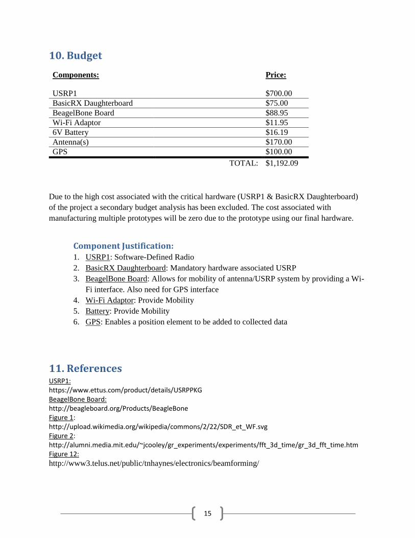
10. Budget
Due to the high cost associated with the critical hardware (USRP1 & BasicRX Daughterboard)
of the project a secondary budget analysis has been excluded. The cost associated with
manufacturing multiple prototypes will be zero due to the prototype using our final hardware.
Component Justification: 1. USRP1: Software-Defined Radio
2. BasicRX Daughterboard: Mandatory hardware associated USRP
3. BeagelBone Board: Allows for mobility of antenna/USRP system by providing a Wi-
Fi interface. Also need for GPS interface
4. Wi-Fi Adaptor: Provide Mobility
5. Battery: Provide Mobility
6. GPS: Enables a position element to be added to collected data
11. References USRP1: https://www.ettus.com/product/details/USRPPKG BeagelBone Board: http://beagleboard.org/Products/BeagleBone Figure 1: http://upload.wikimedia.org/wikipedia/commons/2/22/SDR_et_WF.svg Figure 2: http://alumni.media.mit.edu/~jcooley/gr_experiments/experiments/fft_3d_time/gr_3d_fft_time.htm Figure 12:
http://www3.telus.net/public/tnhaynes/electronics/beamforming/
Components: Price:
USRP1 $700.00
BasicRX Daughterboard $75.00
BeagelBone Board $88.95
Wi-Fi Adaptor $11.95
6V Battery $16.19
Antenna(s) $170.00
GPS $100.00
TOTAL: $1,192.09