Embed Size (px)
Citation preview

GEO-TECHNICAL ENGINEERING DIRECTORATE
Draft specifications have been prepared by Geo-technical Engineering Directorate
of RDSO for various items related to Tunnel construction- tunnel support system,
waterproofing, grouting etc., i.e. SN-Bolts/Rock Bolts, Self Drilling Anchors, Self Drilling
Anchors for Pipe Roofs, Water Expandable Rock bolts/Swellex, Glass Reinforced Plastic
Bolts, PVC Waterproofing Membrane, Non-Woven Polypropylene Geotextile, PU/PUR
grout, Cement Grout for Rock bolts.
Comments/suggestions are invited from industries / individuals having technical
experience and expertise in respective fields with a view to improve upon the following
specifications. Comments/suggestions shall be suggestive in nature, which shall not
alter the basic objective of the specification. Technical reasons supported with enough
documentary evidence, preferably in the fields of Railway applications must be enclosed
with offered comments/suggestions.
Firms/industries/individuals are requested to submit their comments & suggestions on
the Draft Specifications for the above mentioned items by 31.03.2018 to the contact
details as mentioned below:
Mr. Sameer Singh, Joint Director/GE
Research Designs & Standards Organisation (RDSO)
Ministry of Railways,
Manak Nagar, Lucknow-226011
Uttar Pradesh, India
Email- [email protected], [email protected]
Phone No.-0522-2465721

DRAFT SPECIFICATIONS
1. SN-Bolts/ Rock Bolts:
Store-Norfors-Anchors (named after the first place of installation) popularly known as
SN-Anchors are mortar embedded concrete reinforcement steel anchors and are used
for rock reinforcement in underground Mining and Tunneling.
These are made of deformed reinforcing steel with a corrugated surface. Of which one
end shall be fitted with a suitable thread to fix anchor plate with nut. The steel rods
shall be corrosion protected.
Uses:
SN-Bolts/ Rock Bolts are used mainly as a temporary support in tunnels for Ground
support, Rock stabilization and Anchorages in rock.
Installation Procedure:
Drilling of Boreholes
Filling of the borehole with grout
Manual insertion of SN-Anchors into the pre-filled boreholes, fixation in the
borehole using a wedge or similar device
Proper curing is to be done
Tensioning of the bolt’s head by tightening of the nut
Design Considerations and Specifications:
The ground is a vital element of the ground anchor system; therefore a good quality
geotechnical investigation is essential. Various parameters to be considered during
geotechnical investigations should include Classification of rocks (Geometry of
discontinuities, unit weight, degree of weathering, Index test), Rock stratification,
Unconfined compression strength of intact rock, Shear strength and deformability of
rock mass, Permeability, Ground water conditions, Corrosion potentials of rock and
ground water etc.
Moreover, the design of the anchor system is based on rock parameters and the
geometry of the anchor arrangement. Where changes in the anchor locations,
spacing’s or inclinations are proposed, appropriate studies or proving tests should be
undertaken to demonstrate the suitability of such an arrangement. The design of the
anchor should consider the following-

Loads and constraints of loading imposed by the anchors on the overall
structure
The way in which the loads will be applied to the anchor during its
designed life i.e. static or dynamic
The load distribution of the anchor arrangement on the structure during
stressing and during the design life of the structure
The interface between the anchor and the structure to ensure structural
stability
The consequence of anchor failure during stressing and thereafter.
The diameter and tensile strength of bolt and also arrangement (number, spacing
etc.) of rock bolts to be used may vary according to design. The diameter of rock
bolts depend on the mass of the rock to be supported by each rock bolt and the
force of resisting shear in the bedrock.
EN 1997-1 – Geotechnical Design-Part 1: General Rules and BS EN 1537-2000-
Execution of Special Geotechnical work- Ground Anchors may be followed for all
geotechnical designs, installation of Ground Anchors. DIN 1054:2005-01 – Ground
verification of the Safety of Earthworks and Foundations is also being used for
geotechnical designs for ground anchors.
Generally, SN- Bolts having minimum diameter of 25 mm, with a yield load of 200
kN (Min) for steel grade Fe 415 & yield load of 245 kN (Min) for steel grade Fe 500
are used as a temporary support in tunnels. These are the lower limit of
specifications & may vary as per actual site conditions and design requirements;
mechanical properties/requirement accordingly can be adopted from the relevant
codes (IS-1786) (Annexure-II).
Anchor Plate of size 200mm x 200mm (min) and thickness of plate 10mm (min) is
generally used based on support necessities. The shape shall allow a uniform seat
over rock, if the bolt is not installed exactly perpendicular to the surface.
The yield loads of the bolt get transferred through thread to nut, washer, anchor
plate and coupling etc. Hence, these should also be designed accordingly.
SN-Bolts/Rock bolts should conform to Indian Standard code IS-1786: High Strength
Deformed Steel Bars and Wires for Concrete Reinforcement- Specification. Code has

mentioned the mechanical properties of high strength deformed bars (Annexure-I)
and various tests viz. Tensile test, bend test, Rebend test and Retest norms.
The tensile strength, percentage elongation, percentage total elongation at
maximum force and 0.2 percent proof stress of bars/wires shall be determined as
per IS: 1786.
The bend test should be performed in accordance with the requirements of IS 1599
and the mandrel diameter for different grades shall be as specified in Table 4. The
test piece, when cold, shall be doubled over the mandrel by continuous pressure
until the sides are parallel. The specimen shall be considered to have passed the
test if there is no rupture or cracks visible to a person of normal or corrected vision
on the bent portion.
The rebend test should be performed in accordance to IS: 1786. The test piece
shall be bent to an included angle of 1350 using a mandrel of appropriate diameter.
The specimen shall be considered to have passed the test if there is no rupture or
cracks visible to a person of normal or corrected vision on the rebent portion.
The Retest should be performed in accordance to IS: 1786-2008. If any one of the
test pieces first selected fail to pass any of the tests specified in this standard, two
further samples shall be selected for testing in respect of each failure.
Pull out test on Rock Bolts shall be performed as per IS: 11309-1985 – Method for
conducting Pull-Out Test on Anchor Bars and Rock Bolts.
- Minimum three pull out tests shall be conducted in one rock formation as
mentioned in clause 4.8 of IS: 11309-1985 or as per the instructions of Engineer-
in-charge.

Annexure-I
Sl No. Property Fe 415 Fe415 D Fe415 S Fe 500 Fe500 D Fe500 S Fe550 Fe550 D Fe 600
1 2 3 4 5 6 7 8 9 10 11
i)
0.2 percent proof
stress/ yield
stress, Min.
N/mm2
415 415 415 500 500 500 550 550 600
ii)
0.2 percent proof
stress/ yield
stress, Max.
N/mm2
540 625
iii)TS/YS ratio,
N/mm2
>1.10, but TS
not lessthan
485 N/mm2
>1.10, but TS
not lessthan
500 N/mm2
1.25
>1.08, but
TS not less
than 545
N/mm2
>1.10, but
TS not less
than 565
N/mm2
1.25
>1.06, but
TS not less
than 555
N/mm2
>1.08, but
TS not less
than 600
N/mm2
>1.06, but
TS not less
than 660
N/mm2
iv)
Elongation
percent, min. on
gauge length 5.65
√A , where A is the
cross-sectional
area of the test
piece.
14.5 18 20 12 16 18 10 14.5 10
v)
Total elongation at
maximum
force, percent,
Min, on gauge
where A is the
cross-sectional
area of the test
piece
5 10 5 8 5
Table 3 Mechanical properties of High Strength Deformed Bars and Wires (AS per IS: 1786-2008)
TY/SY Ratio refers to ratio of tensile strength of the 0.2 percent proof stress or yield stress of the test piece.

2. Self-Drilling Anchors:
Self-Drilling Anchor bolts are a combined system of rock bolt and drill rod. During
drilling, the bolts is used as the drill rod fixed with a drill bit, rod and bit remain in the
hole as a rock bolt, which is grouted through the flushing hole. In case of collapsing
boreholes, this system still enables the installation of rock bolts for very common
flexible rock support to anchor the fractured rock mass in the tunnel and gives the
strength and stability to the ground.
Use:
Self-Drilling Rock Bolt is a rock-bolting system based on fully coarse threaded hollow
bar. It is especially recommended for the following applications:
Roof and wall bolting as a temporary support in tunnels.
All ground conditions. Self-Drilling Rock Bolts do not require pre-drilling a hole,
therefore making it usable even in soft rock conditions.
Self-drilling bolts shall be used in ground conditions where the effective
installation of other types of rock bolts is impossible.
For loose ground/ fractured rock conditions, where drill holes collapses
immediately during the drilling, the Self Drilling Anchors can provide immediate
stabilization of the opening.
It shall be grouted through the flushing hole immediately after completion of the
drilling operation or simultaneously with the drilling as required.
Installation Procedure:
Drilling, grouting, and anchoring, in one operation. The hollow steel anchor rod also
acts as a grouting pipe to ease set up.
Design Considerations and Specifications:
The ground is a vital element of the ground anchor system; therefore a good quality
geotechnical investigation is essential. Various parameters to be considered during
geotechnical investigations should include Classification of rocks (Geometry of
discontinuities, unit weight, degree of weathering, Index test), Rock stratification,
Unconfined compression strength of intact rock, Shear strength and deformability of
rock mass, Permeability, Ground water conditions, Corrosion potentials of rock and
ground water etc.

Moreover, the design of the anchor system is based on rock parameters and the
geometry of the anchor arrangement. Where changes in the anchor locations,
spacing’s or inclinations are proposed, appropriate studies or proving tests should be
undertaken to demonstrate the suitability of such an arrangement. The design of the
anchor should consider the following-
Loads and constraints of loading imposed by the anchors on the overall
structure
The way in which the loads will be applied to the anchor during its
designed life i.e. static or dynamic
The load distribution of the anchor arrangement on the structure during
stressing and during the design life of the structure
The interface between the anchor and the structure to ensure structural
stability
The consequence of anchor failure during stressing and thereafter.
The diameter and tensile strength of bolt and also arrangement (number, spacing
etc.) of rock bolts to be used may vary according to design and site requirements.
The diameter of rock bolts depend on the mass of the rock to be supported by each
rock bolt and the force of resisting shear in the bedrock.
EN 1997-1 – Geotechnical Design-Part 1: General Rules and BS EN 1537-2000-
Execution of Special Geotechnical work- Ground Anchors may be followed for all
geotechnical designs, installation of Ground Anchors. DIN 1054:2005-01 – Ground
verification of the Safety of Earthworks and Foundations IS is also being used for
geotechnical designs for ground anchors.
Generally, Self-drilling Anchors/bolts having minimum diameter 32 mm with a
minimum yield load of 200 kN are used for Rock bolting/ Face bolting as a
temporary support in tunnels. These are the lower limit of specifications & may vary
as per actual site conditions and design requirements; mechanical
properties/requirement accordingly can be adopted from the relevant codes (EN-
10083-1) (Annexure-II).
Adverse interactions of anchorages should be avoided, by keeping a space not less
than 1.5 m between them, if possible.

The yield loads of the bolt get transferred through thread to nut, washer, anchor
plate and coupling etc. Hence, these should also be designed accordingly. The rolled
thread should be in accordance with ISO 10208.
Manufacturing of Self-drilling Anchors should conform to BS EN-10083-1 “Steels for
quenching and tempering - Part 1: General technical delivery conditions”.
For all types of Self-drilling Anchors, the anchor head shall be designed in
accordance to EN 1537:1999, and should be able to accommodate deformations,
which may occur during the design life of the structure.
Corrosion protection of Self-drilling Anchors should comply with Para 6.9 of EN
1537:1999 as required.
Tensile test of Self-drilling Anchors is done in accordance to EN 10002-1. The test
involves straining a test piece in tension, generally to fracture, for the purpose of
determining one or more of the mechanical properties i.e. percentage elongation,
tensile strength, yield strength, upper yield strength etc.
Impact test of Self-drilling Anchors should be done is done in accordance to EN
10045-1. The test consists of breaking by one blow from a swinging pendulum,
under conditions defined in code above. The energy absorbed is a measure of the
impact strength of the material.
Pull out test on Self-drilling Anchors should be performed of on the basis of IS:
11309 – Method for conducting Pull-Out Test on Anchor Bars and Rock Bolts.
- Minimum three pull out tests shall be conducted in one rock formation as
mentioned in clause 4.8 of IS: 11309-1985 or as per the instructions of
Engineer-in-charge.
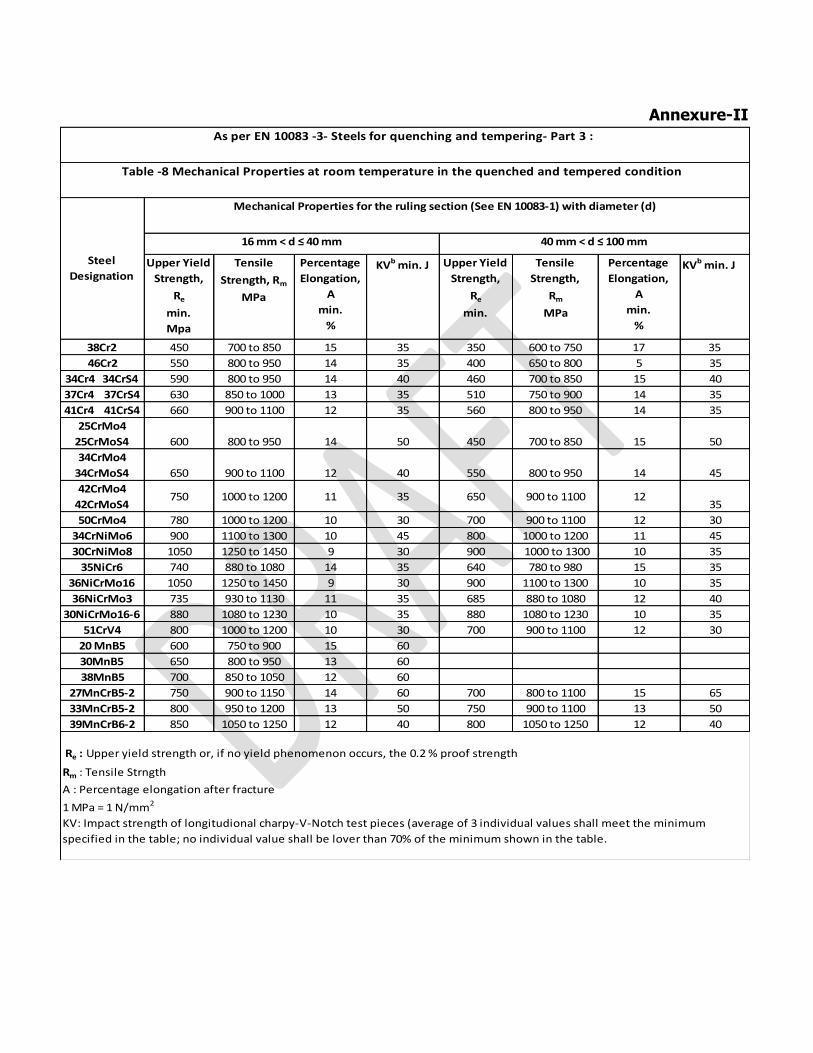
Annexure-II
Upper Yield
Strength,
Re
min.
Mpa
Tensile
Strength, Rm
MPa
Percentage
Elongation,
A
min.
%
KVb min. J Upper Yield
Strength,
Re
min.
Tensile
Strength,
Rm
MPa
Percentage
Elongation,
A
min.
%
KVb min. J
38Cr2 450 700 to 850 15 35 350 600 to 750 17 35
46Cr2 550 800 to 950 14 35 400 650 to 800 5 35
34Cr4 34CrS4 590 800 to 950 14 40 460 700 to 850 15 40
37Cr4 37CrS4 630 850 to 1000 13 35 510 750 to 900 14 35
41Cr4 41CrS4 660 900 to 1100 12 35 560 800 to 950 14 35
25CrMo4
25CrMoS4 600 800 to 950 14 50 450 700 to 850 15 50
34CrMo4
34CrMoS4 650 900 to 1100 12 40 550 800 to 950 14 45
42CrMo4
42CrMoS4750 1000 to 1200 11 35 650 900 to 1100 12
35
50CrMo4 780 1000 to 1200 10 30 700 900 to 1100 12 30
34CrNiMo6 900 1100 to 1300 10 45 800 1000 to 1200 11 45
30CrNiMo8 1050 1250 to 1450 9 30 900 1000 to 1300 10 35
35NiCr6 740 880 to 1080 14 35 640 780 to 980 15 35
36NiCrMo16 1050 1250 to 1450 9 30 900 1100 to 1300 10 35
36NiCrMo3 735 930 to 1130 11 35 685 880 to 1080 12 40
30NiCrMo16-6 880 1080 to 1230 10 35 880 1080 to 1230 10 35
51CrV4 800 1000 to 1200 10 30 700 900 to 1100 12 30
20 MnB5 600 750 to 900 15 60
30MnB5 650 800 to 950 13 60
38MnB5 700 850 to 1050 12 60
27MnCrB5-2 750 900 to 1150 14 60 700 800 to 1100 15 65
33MnCrB5-2 800 950 to 1200 13 50 750 900 to 1100 13 50
39MnCrB6-2 850 1050 to 1250 12 40 800 1050 to 1250 12 40
Re : Upper yield strength or, if no yield phenomenon occurs, the 0.2 % proof strength
Rm : Tensile Strngth
A : Percentage elongation after fracture
1 MPa = 1 N/mm2
KV: Impact strength of longitudional charpy-V-Notch test pieces (average of 3 individual values shall meet the minimum
specified in the table; no individual value shall be lover than 70% of the minimum shown in the table.
Steel
Designation
As per EN 10083 -3- Steels for quenching and tempering- Part 3 :
Table -8 Mechanical Properties at room temperature in the quenched and tempered condition
Mechanical Properties for the ruling section (See EN 10083-1) with diameter (d)
16 mm < d ≤ 40 mm 40 mm < d ≤ 100 mm

3. Self-drilling Anchors for Pipe roofs:
Self-drilling Anchors for pipe roofs is a pre support measure used in weak ground
condition in conventional as well as mechanized tunneling. Pipe umbrella pipes increase
the stability in the working area by transferring loads in the longitudinal direction and
decrease excavation induced deformation. The system increase safety in the working
area.
Uses: Roof and wall bolting as a temporary support in tunnels.
Installation Procedure:
Drilling, grouting, and anchoring, in one operation. The hollow steel anchor rod also
acts as a grouting pipe to ease set up.
Design Considerations and Specifications:
The ground is a vital element of the ground anchor system; therefore a good quality
geotechnical investigation is essential. Various parameters to be considered during
geotechnical investigations should include Classification of rocks (Geometry of
discontinuities, unit weight, degree of weathering, Index test), Rock stratification,
Unconfined compression strength of intact rock, Shear strength and deformability of
rock mass, Permeability, Ground water conditions, Corrosion potentials of rock and
ground water etc.
Moreover, the design of the anchor system is based on rock parameters and the
geometry of the anchor arrangement. Where changes in the anchor locations,
spacing’s or inclinations are proposed, appropriate studies or proving tests should be
undertaken to demonstrate the suitability of such an arrangement. The design of the
anchor should consider the following-
Loads and constraints of loading imposed by the anchors on the overall
structure
The way in which the loads will be applied to the anchor during its
designed life i.e. static or dynamic
The load distribution of the anchor arrangement on the structure during
stressing and during the design life of the structure
The interface between the anchor and the structure to ensure structural
stability
The consequence of anchor failure during stressing and thereafter.

The diameter and tensile strength of bolt and also arrangement (number, spacing
etc.) of rock bolts to be used may vary according to design. The diameter of rock
bolts depend on the mass of the rock to be supported by each rock bolt and the
force of resisting shear in the bedrock.
EN 1997-1 – Geotechnical Design-Part 1: General Rules and BS EN 1537-2000-
Execution of Special Geotechnical work- Ground Anchors may be followed for all
geotechnical designs, installation of Ground Anchors. DIN 1054:2005-01 – Ground
verification of the Safety of Earthworks and Foundations IS is also being used for
geotechnical designs for ground anchors.
Generally, Self-drilling Anchors for pipe roofs having minimum diameter 76 mm with
a minimum yield load of 1200 kN are used as a temporary support in tunnels. These
are the lower limit of specifications & may vary as per actual site conditions and
design requirements; mechanical properties/requirement accordingly can be adopted
from the relevant codes (EN-10083-1) (Annexure-III).
The yield loads of the bolt get transferred through thread to nut, washer, anchor
plate and coupling etc. Hence, these should also be designed accordingly. The rolled
thread should be in accordance with ISO 10208.
Manufacturing of Self-drilling Anchors for pipe roof should conform to BS EN-10083-
1 “Steels for quenching and tempering - Part 1: General technical delivery
conditions”.
For all types of Self-drilling Anchors for pipe roof, the anchor head shall be designed
in accordance to EN 1537:1999, and should be able to accommodate deformations,
which may occur during the design life of the structure.
Corrosion protection of Self-drilling Anchors for pipe roof should comply with Para
6.9 of EN 1537:1999.
Tensile test of Self-drilling Anchors for pipe roof should be done in accordance to EN
10002-1. The test involves straining a test piece in tension, generally to fracture, for
the purpose of determining one or more of the mechanical properties i.e.
percentage elongation, tensile strength, yield strength, upper yield strength etc.

Impact test of Self-drilling Anchors for pipe roof should be done in accordance to EN
10045-1. The test consists of breaking by one blow from a swinging pendulum,
under conditions defined in code above. The energy absorbed is a measure of the
impact strength of the material.
Pull out test on Self-drilling Anchors for pipe roof should be performed of on the
basis of IS: 11309 – Method for conducting Pull-Out Test on Anchor Bars and Rock
Bolts.
- Minimum three pull out tests shall be conducted in one rock formation as
mentioned in clause 4.8 of IS: 11309-1985 or as per the instructions of
Engineer-in-charge.

Annexure-III
Upper Yield
Strength,
Re
min.
Mpa
Tensile
Strength, Rm
MPa
Percentage
Elongation,
A
min.
%
KVb min. J Upper Yield
Strength,
Re
min.
Tensile
Strength,
Rm
MPa
Percentage
Elongation,
A
min.
%
KVb min. J
38Cr2 450 700 to 850 15 35 350 600 to 750 17 35
46Cr2 550 800 to 950 14 35 400 650 to 800 5 35
34Cr4 34CrS4 590 800 to 950 14 40 460 700 to 850 15 40
37Cr4 37CrS4 630 850 to 1000 13 35 510 750 to 900 14 35
41Cr4 41CrS4 660 900 to 1100 12 35 560 800 to 950 14 35
25CrMo4
25CrMoS4 600 800 to 950 14 50 450 700 to 850 15 50
34CrMo4
34CrMoS4 650 900 to 1100 12 40 550 800 to 950 14 45
42CrMo4
42CrMoS4750 1000 to 1200 11 35 650 900 to 1100 12
35
50CrMo4 780 1000 to 1200 10 30 700 900 to 1100 12 30
34CrNiMo6 900 1100 to 1300 10 45 800 1000 to 1200 11 45
30CrNiMo8 1050 1250 to 1450 9 30 900 1000 to 1300 10 35
35NiCr6 740 880 to 1080 14 35 640 780 to 980 15 35
36NiCrMo16 1050 1250 to 1450 9 30 900 1100 to 1300 10 35
36NiCrMo3 735 930 to 1130 11 35 685 880 to 1080 12 40
30NiCrMo16-6 880 1080 to 1230 10 35 880 1080 to 1230 10 35
51CrV4 800 1000 to 1200 10 30 700 900 to 1100 12 30
20 MnB5 600 750 to 900 15 60
30MnB5 650 800 to 950 13 60
38MnB5 700 850 to 1050 12 60
27MnCrB5-2 750 900 to 1150 14 60 700 800 to 1100 15 65
33MnCrB5-2 800 950 to 1200 13 50 750 900 to 1100 13 50
39MnCrB6-2 850 1050 to 1250 12 40 800 1050 to 1250 12 40
Re : Upper yield strength or, if no yield phenomenon occurs, the 0.2 % proof strength
Rm : Tensile Strngth
A : Percentage elongation after fracture
1 MPa = 1 N/mm2
KV: Impact strength of longitudional charpy-V-Notch test pieces (average of 3 individual values shall meet the minimum
specified in the table; no individual value shall be lover than 70% of the minimum shown in the table.
Steel
Designation
As per EN 10083 -3- Steels for quenching and tempering- Part 3 :
Table -8 Mechanical Properties at room temperature in the quenched and tempered condition
Mechanical Properties for the ruling section (See EN 10083-1) with diameter (d)
16 mm < d ≤ 40 mm 40 mm < d ≤ 100 mm

4. Water Expandable Rock Bolts (Swellex-type):
The Swellex rock bolting system consists of specific rock bolts made from steel tubes
that have been folded onto themselves, with bolting accessories and high pressure,
installation pumps.
Swellex rock bolts are placed in drilled holes and expanded using water from the
installation pump. The high pressure water causes the bolts to expand, filling the drill
hole, consolidating any loose material remaining after drilling and conforms to the
irregularities of the hole. A combination of friction and mechanical interlock is generated
throughout the entire bolt length.
Swellex bolts interact directly with the rock without the need for such auxiliaries
as grouting agents or locking devices. Simply monitoring water pressure provides
quality control during installation. It gives immediate full load bearing capacity over the
entire installed bolt length with low sensitivity against vibrations caused by blasting
works. Swellex rock bolts are safe and easy to install & with no grouting required, this
helps to avoid contamination also.
Use:
Water Expandable Rock Bolts/ Swellex rock bolting system has gained wide recognition
in mining and tunneling works. Swellex is a family of ground support system that covers
such demanding applications as high loading, deep support, large rock deformations
and corrosive environments.
Installation Procedure:
Drill the hole.
Swellex bolt is placed.
Water injected under pressure forms the tube to the irregularities of the bore
hole, generating friction and mechanical interlocking.
The internal pressure is released leaving a permanently deformed tube that is
locked in place providing a strong interaction with the rock mass.
Design Considerations and Specifications:
The ground is a vital element of the ground anchor system; therefore a good quality
geotechnical investigation is essential. Various parameters to be considered during
geotechnical investigations should include Classification of rocks (Geometry of
discontinuities, unit weight, degree of weathering, Index test), Rock stratification,
Unconfined compression strength of intact rock, Shear strength and deformability of

rock mass, Permeability, Ground water conditions, Corrosion potentials of rock and
ground water etc.
Moreover, the design of the anchor system is based on rock parameters and the
geometry of the anchor arrangement. Where changes in the anchor locations,
spacing’s or inclinations are proposed, appropriate studies or proving tests should be
undertaken to demonstrate the suitability of such an arrangement. The design of the
anchor should consider the following-
Loads and constraints of loading imposed by the anchors on the overall
structure
The way in which the loads will be applied to the anchor during its
designed life i.e. static or dynamic
The load distribution of the anchor arrangement on the structure during
stressing and during the design life of the structure
The interface between the anchor and the structure to ensure structural
stability
The consequence of anchor failure during stressing and thereafter.
The diameter and tensile strength of bolt and also arrangement (number, spacing
etc.) of rock bolts to be used may vary according to design. The diameter of rock
bolts depend on the mass of the rock to be supported by each rock bolt and the
force of resisting shear in the bedrock.
EN 1997-1 – Geotechnical Design-Part 1: General Rules and BS EN 1537-2000-
Execution of Special Geotechnical work- Ground Anchors may be followed for all
geotechnical designs, installation of Ground Anchors.
Generally, Swellex rock bolts with a minimum yield load of 150 kN are used as
temporary support in a tunnel. Rock bolt of higher strength may be used as per
actual geological site condition and design requirements.
Minimum external diameter of Omega (Ω) profile & external diameter for expanded
profile should be 36 mm and 54 mm respectively having minimum wall thickness 2
mm. Borehole diameter should be between 43-52 mm for the external diameter as
recommended above.
These are the lower limit of specifications & may vary as per actual site conditions
and design requirements; mechanical properties/requirement accordingly can be
adopted from the relevant codes (BS EN-10149 Part-1).

Manual as well as automated installation is done by expansion of the omega (Ω)
shaped profile with high-pressure water of 300 bar for external diameter of bolts as
recommended above.
For installation of Swellex bolts, equipment as recommended by the manufacturer of
the bolts shall be used.
Manufacturing of Swellex-Bolts should conform to BS EN 10149-1 – Specifications
for Hot-rolled flat products made of high yield strength steels for cold forming. Table
placed as Annexure IV shows various mechanical properties of thermo-mechanically
rolled steels.
Corrosion protection of Swellex bolts should comply with Para 6.9 of EN 1537:1999.
Tensile test of Swellex bolts is done in accordance to BS EN 10149-1 & EN 10002-1.
The test involves straining a test piece in tension, generally to fracture, for the
purpose of determining one or more of the mechanical properties i.e. percentage
elongation, tensile strength, yield strength, upper yield strength etc.
Impact test of Swellex bolts should be done is done in accordance to BS EN 10149-
1. The test consists of breaking by one blow from a swinging pendulum, under
conditions defined in code above. The energy absorbed is a measure of the impact
strength of the material. The minimum impact energy value will be 40 Joules.
The Bend test shall be carried out in accordance with Euro-norms 6 & 12.
Pull out test on Swellex bolts should be performed of on the basis of IS: 11309 –
Method for conducting Pull-Out Test on Anchor Bars and Rock Bolts.
- Minimum three pull out tests shall be conducted in one rock formation as
mentioned in clause 4.8 of IS: 11309-1985 or as per the instructions of
Engineer-in-charge.

Annexure-IV
5. Glass-reinforced Plastic (GRP) Bolts:
GRP Bolts are fiber bolts made of glass fiber reinforced with strengthened plastic. Glass-
reinforced Plastic (GRP) Bolts are used for face bolting as temporary support measure.
It is used where bedrock is to be reinforced in advance so that it may be easily cut by
boring in later process.
Uses:
Face-bolting and temporary applications: Cut-ability of GRP makes it the ideal solutions
for face bolting or any other tunneling/mining application where face support is
required for further excavation.
Specifications:
GRP Bolts are used for face bolting of the tunnel to reinforce it in advance as per
actual geological site condition and requirements.
It gives high flexibility which is well suited for application without couplings in
confined locations.
Generally, GRP Bolts having minimum nominal diameter of 20 mm for Solid/Hollow
/Self- Drilling Bolts. The Minimum tensile strength should be 850 N/mm2. The
minimum torsional strength of GRP bolts shall be 100 Nm in both directions. These
are the lower limit of specifications & may vary as per actual site conditions and
design requirements.
GRP Bolts should conform to BS 7861-1-Strata reinforcement support system-
specification for rock-bolting.
Tensile strength test is done in accordance with Annexures - H of BS 7861-1. It
is determined by subjecting the test sample to a tensile force until failure occurs.
Flexural Strength test is done in accordance with Annexure - J of BS 7861-1; it is
determined by subjecting a test specimen to a three point bend test. The
material shall have a flexural strength of not less than 750 N/mm2.
Torsional strength test is done in accordance with Annexure-G of BS-7861-1; it is
determined by subjecting the test sample to a torsional force in both directions
until failure occurs.

6. Cement Grout for Rock Bolting
Rockbolts have been used for many years for the support of underground excavations.
Rock bolts are used as the main support for structures such as tunnels and mines
where safety is critical. For proper anchorage/bonding between Bolt and surrounding
Rock mass, all bolt holes must be grouted completely with cement grout.
Functions of Grouting:
a) To form the fixed anchor length in order that the applied load may be transferred
from the bolts to the surrounding ground.
b) To protect the bolt against corrosion.
c) To strengthen the ground immediately adjacent to the fixed anchor in order to
enhance the ground anchor capacity.
d) To seal the ground immediately adjacent to the fixed anchor length in order to
limit the loss of grout.
Note: If a grout volume injected is in excess of three times the borehole volume at
pressures not exceeding total overburden pressure, then general void filling is indicated
which is beyond routine anchor construction. In such cases pre-grouting void filling may
be necessary before grouting the anchor.
Placement of grout should be carried out as soon as possible after completion of
drilling.
Generalized specifications of cement grout are as under:
1. The cement grout shall be mechanically mixed to produce a uniform consistency.
2. The selection of the type of cement for the grout should consider the
aggressiveness of the environment, the permeability of the ground and the
design life of the bolts.
3. The aggressiveness of environment may be determined in accordance with EN
206-1 & taken into consideration as required.
4. Ordinary Portland cement shall be used. (BIS 269: 2015). It shall be compatible
with the reinforcing elements.
5. The cement grout shall conform to EN 14490.

6. Water /cement ratios (weight-ratio) should be appropriate to the ground
conditions, anchorage system construction method, durability and strength
requirements. Maximum water cement ratio to be limited to 0.55 to ensure
barrier against corrosion and other aggressive agents and stress.
7. Typically, grout should achieve a minimum characteristic strength of 5 Mpa prior
to load being induced in the grouted anchor, and the 28 days characteristic
strength of the grout mix should not be less than 25 MPa.
8. Thixotropic consistency to make grouts suitable for vertical holes.
9. It should have enough workability for easy pumping and placement.
10. The bolt/ dowel shall be protected against disturbance for a minimum time of 48
hours after installation or more as required by Engineer-in-charge.
11. After the grout has gained adequate strength, washer plates shall tighten against
the rock face, so as to induce positive compression in rock mass around the
bolts.
12. Inert fillers may be incorporated within the grout, for example the introduction of
sand. Sand for grouting purpose shall be clean mineral sand, uniform in quality
and from an approved source. Water shall be clean, free from oil, acid, alkaline,
organic and other deleterious substances. This material shall be approved by the
Engineer.
13. Admixtures may be used for improving workability, durability, reducing bleed,
reducing shrinkage or adjusting rate of setting and strength development.
14. Admixtures should not contain any product liable to damage the reinforcing
element or the grout itself. Admixtures that contain more than 0.1% by mass
chlorides, sulphates or nitrates should not be used.

7. Waterproofing system Waterproofing system for watertight (dry) tunnel may consist of two layers; the first
shall consist of protective felt fastened to the shotcrete surface: the second layer shall
be the actual waterproofing membrane properly fixed by special mean as recommended
by manufacturer.
Waterproofing Membrane
The purpose of waterproofing membrane for underground structures is to prevent
leakage of groundwater into the tunnel and to protect the final concrete lining against
deleterious chemical influences. Waterproofing shall be applied to crown and sidewalls
above footing or inverted arch level.
Specifications
As per IS-15909: PVC Geomembrane for Lining Specification
The PVC geomembrane shall be suitably manufactured from vinyl chloride resin homo
polymer. Water soluble compounding ingredient shall not be used. Plasticizers that are
resistant to migration and bacterial growth shall be used.
The thickness of geomembrane generally for this application shall be 2mm with
allowable tolerance of ±7.5%. (para 3.2 of IS 3464)
In case two or more layers of PVC films are used. These shall be joint together
by a suitable heat fusion lamination only, having minimum peel strength of 1.05
kN/m.(para 12 of IS 3464)
The PVC geomembrane shall be reasonably free from defects such as holes, tear
or blisters.
Specific gravity should be ranging from 1.3 to 1.4.(Appendix A (Method A)of IS
2076)
It shall have tensile strength of ≥160 kg/cm2, and elongation at break of ≥
250%.(Appendix B of IS 2076)
The tear strength of membrane should be minimum of 110 N in machine
direction & 80 N in cross direction, determined in according with the method
described in (Annexure A of IS 15909).

It shall have Index puncture resistance of ≥ 525 N.(Annexure B of IS 15909)
For low temperature crack resistance, geomembrane shall not crack when bend
1800 by hand over the mandrel at a temperature of -30±20C. (Annexure C of IS
15909)
It shall have hydrostatic resistance of ≥25 kg/cm2.(Annexure D of IS 15909-
Test specimen is clamped in between two circular clamps of about 76mm dia.
The pressure is generated by means of piston forcing water into the pressure
chamber of the apparatus at rate of 1.4±0.1 cm3/s until the specimen fails.)
It shall have Seam strength of ≥75 % of original value. (Annexure E of IS 15909-
Specimen is placed in the jaws of the tensile testing machine with the seam
centered between and parallel to the jaws and width of the specimen at right
angles to the direction of application of force. Record the necessary load to slip
the seam or rupture the specimen is recorded to get the seam strength)
The maximum volatile matter in the geomembrane shall be limited to 1%. The
loss of mass of PVC membrane shall be express as volatile loss when it place in
oven at temperature 100± 20C for 6 hours.(para 7 of IS 3464)
Maximum change in Tensile strength and Elongation at break after buried in soil
shall be 5% and 20% respectively. (Annexure F of IS 15909 – Test specimen is
buried in soil that is rich in cellulose destroying microorganism to the depth of
about 200 to 500 mm. After 30 days determine the tensile strength and
elongation at break.)
Reduction in weight of geomembrane after being immersed completely in
distilled water for 24 hours at room temperature should not be greater than
0.15%.(Annexure G of IS 15909)
Stability to UV radiations, percent retention in tensile strength and elongation at
break of shall be ≥80%, when expose to ultraviolet radiation in a Xenon-arc
apparatus for 500 hrs. (Annexure H of IS 15909)

Draft recommended specifications of PVC waterproofing membrane
S.N Property Requirement
Standard
1. Length and width
As agreed (Tolerance ± 1%)
Para 3.4 of IS 3464
2. Thickness (mm)
2 (Tolerance ± 7.5%)
Para 3.2 of IS 3464
3. Specific gravity 1.3 - 1.4
Appendix A (Method A)of IS 2076
4. Tensile strength (kg/cm2) ≥160
Appendix B of IS 2076
5. Elongation at break ≥ 250%
Appendix B of IS 2076
6. Tear strength, N a) Machine direction b) Cross direction
≥110 ≥80
Annexure A of IS 15909
7. Index Puncture Resistance, N ≥525
Annexure B of IS 15909
8. Low temperature crack resistance
Shall not break ,crack at -30± 20C
Annexure C of IS 15909
9. Hydrostatic resistance, kg/cm2 ≥25
Annexure D of IS 15909
10. Seam strength, kg
≥75% of original value
Annexure E of IS 15909
11. Volatile loss ≤1% Para 7 of IS 3464
12. Peel strength, KN/m ≥1.05 Para 12 of IS 3464
13. Resistance to soil burial a) Tensile strength percentage
change b) Elongation at break
percentage change
≤5 ≤20
Annexure F of IS 15909
14. Water extraction, percentage loss in weight
≤0.15 Annexure G of IS 15909
15. Stability to ultraviolet radiations, percentage in tensile strength and elongation at break.
≥80 Annexure H of IS 15909

8. Non-Woven Poly-Propylene Geo-Textile
It is a layer of protective felt fastened to the shotcrete surface which is a continuous
filament non-woven poly-propylene geotextile of uniform thickness and surface texture,
which shall meet the draft specification as listed below.
Use
The typical use will be as a protective covering or underlayment of a geomembrane
against puncture or tear due to rock, stones, concrete or other hard surface and/or
objects.
Specifications:
For these applications, Geo-Textile shall have minimum unit weight of 500g/m2.
(Testing as per ASTM D-5261).
It shall have a minimum tensile strength of 1.64 kN with extension at break of 70%
(minimum). (ASTM D 4632- A Continually increasing load is applied longitudinally to
the specimen and the test is carried to rupture. Values for the breaking load and
elongation of the test specimen are obtained.)
Minimum Trapezoidal Tear Strength of the geotextile should be 0.64 kN. (Testing as
per ASTM D-4533).
Maximum 10% loss of strength is allowable for the Geo-Textile, when tested for
resistance against acid and alkaline solution pH 2-13. (EN : 14030- Specimen
completely immersed in a test liquid for 3 days at a temperature of 60 ± 10 C.
Properties of the test specimen are tested before and after immersion).
Resistance to punching should be a minimum of 4000 N. (ASTM D-6241- A test
specimen is clamped without tension between circular plates and secured in a
tensile testing machine. A force is exerted against the centre of the unsupported
portion of the test specimen by a steel plunger attached to the load indicator until
rupture occurs. The maximum force is the value of puncture strength).
Stability to UV radiations; Percent retention in tensile strength and elongation at
break shall be ≥70%, when expose to ultraviolet radiations in a Xenon-arc
apparatus for 500 hrs. (ASTM D-4355)

Draft Recommended Specification of Non-woven poly-propylene Geo-textile
(Protective layer)
Properties
Specified Value Standard
Unit weight
500 g/m2 minimum ASTM D-5261 or Equivalent EN
Tensile Strength
≥1.64 kN ASTM D-4632 or Equivalent EN
Extension at break
≥50 % ASTM D-4632 or Equivalent EN
Trap. Tear strength
≥0.64 kN ASTM D-4533 or Equivalent EN
Resistance to Punching
≥4000 N ASTM D-6241 or Equivalent EN
Resistance against acid and alkaline solution pH 2-13
Loss of strength 10% max
EN : 14030 or Equivalent ASTM
UV Resistance @ 500 hrs
≥70% ASTM D-4355 or Equivalent EN
Note: All values are Minimum Average Roll Value (MARV) except UV resistance, which
is derived statistically as average value minus two standard deviations.
Reference:- GRI ; GT12(a) for “ Test Methods and Properties for Nonwoven Geotextiles
Used as Protection (or Cushioning) Material”

9. Polyurethane Grout
Definition:
Polyurethane Grout comes under Chemical grout which has sufficient fluidity to be
injected or pumped in to a porous body or into crack that reacts in place to form a gel,
foam or solid.
Uses & Purpose:
Polyurethane grouting is considered to be the most common defense towards water
ingress in tunnel. It is a technique that involves the injection of expanding polyurethane
to cutoff water flow through joints or cracks or to fill voids beneath or behind
subsurface of excavated area.
It can be single or multi component grout and can react when coming in contact with
water or require a reactant. The grout is injected with pressure through a predrilled
hole, grout then expands to fill the crack or void.
Many polyurethane grout products are available with variation in viscosity, reaction
time, reaction with water, expansion characteristics and flexibility of reacted grout. It is
important to select proper grout for specific site conditions based on techno-economic
consideration. Polyurethane grout is being used as remedial measures to divert the
water seepage and may assist in rock mass stabilization. It is also to be noted that PU
grouting is not an alternate to rock bolting for rock mass stabilisation.
Before grouting a rock mass, there are a number of important considerations that
will help maximize the efficiency and effectiveness of grouting.
Rock mass characterization is important. From the characterization of the rock
mass, one can estimate the void space within the target zone, which is extremely
important when applying Polyurethane grouting.
By estimation of void space one can estimated the amount of Polyurethane needed
to be pumped into the rock for stabilization.
It is very important to perform an accurate and thorough investigation of the rock
mass, because these considerations will subsequently drive the design decisions for
the project, including the selection of the most appropriate Polyurethane product
The Polyurethane products should be injected at an air/structure temperature
between 130 and 320 C, if product is installed above or below this temperature the
resin viscosity and set time will be affected.

PU and PUR product may be used after observing the number of mixing
components, reactivity with water, and application setting etc.
PU Grout
Polyurethane (PU) is extremely versatile plastics in terms of forms in which they
are available: flexible or rigid foams, solid elastomers, coatings, adhesives and
sealants.
Polyurethane (PU) generally only requires a single stage mix component with an
accelerator added to set the reaction time. Set time can vary widely, ranging from
15 seconds to several hours.
Single stage PU products, using foam or gels, are commonly used for crack repair,
void filling, consolidation of weak strata and ground water contaminant flow
barrier.
They form foam extensively in presence of water. PU single stage grouts are
generally lower in strength and are considered more as water sealant (especially
for hydrophilic type grout) than a stabilization purpose.
Draft Specification:
Property Polyurethane (PU)
Components Mixing One Stage
Injection Type Foam/Gels/Grout
Injection Pressures Low to High (100-3000 psi) (0.7-20.7 MPa)
Density
Low to Medium
3- 50 pcf (0.05-0.8 g/cm3), Testing as per
ASTM D 4659
Compressive/Tensile Strength
Low
10 – 500 psi (0.07-3.44 MPa)
Tensile Strength testing as per ASTM D 638.
Compressive Strength as per ASTM D 695
Viscosity Low to Medium
Water Interaction Hydrophilic
Expansion/Elongation Varies 10 – 3000 %
Shrinkage Varies 1 – 10 %

PUR Grout
Polyurethane resins (PUR) most commonly fall within the category of a two stage
mix component system. In general PUR considered a higher strength injection
grout used for rock stabilization.
The set time can vary from seconds to hours depending on application and
temperature.
Two stage mix system products have greater compressive and tensile strengths
than single stage mix system.
Fractured incompetent rock strata are injected under pressure with two
components at a ratio 1:1 for stabilization, forming an elastomer known as glue.
This provides supplementary support of weak areas and structures.
PUR grouts are being used to stabilize rock mass as well as to divert the excessive
water seepage.
Draft Specification:
Property Polyurethane Resin (PUR)
Components Mixing Two Stage
Injection Type Grout
Injection Pressures Low to High (10-3000 psi) (0.07-20.7 MPa)
Density Medium to High 20 - 70 pcf (0.32-1.12 g/cm3)
Testing as per ASTM D 4659
Compressive/Tensile
Strength
Low to High 15 – 20000 psi (0.01-138 Mpa)
Tensile Strength testing as per ASTM D 638.
Compressive Strength testing as per ASTM D 695
Viscosity Low to High
Water Interaction Hydrophilic/Hydrophobic
Expansion/Elongation Varies 10 – 3000 %
Shrinkage Varies 0 – 3 %
It should be noted that the properties given in above tables provide relative
comparison of products; there are always exceptions, and products can be
manufactured with different component mixes to address a broad range of
applications.
Many polyurethane grout products are available with variation in viscosity,
reaction time, reaction with water, expansion characteristics and flexibility of

reacted grout. It is important to select proper grout for specific site conditions
based on techno-economic consideration.
Application of PU & PUR grout are site specific and hence properties will vary
accordingly and while selecting the proper product and carrying out work on site,
expertise in this field is required.
Ref: 1.Polyurethane Resin (PUR) injection for rock mass stabilization
Publication No. FHWA-CFL/TD-08-004/September-2008
2.Performance of Polyurethane grouting to handle heavy seepage in tunnels,
By N Rana and R Nair, L& T Construction, Chennai
3. Polyurethane grouting technologies, By Jan Bodi, Zoltan Bodi,Jiri Scucka
and Petr Martinec