Embed Size (px)
Citation preview
8/6/2019 Geodesic Math
http://slidepdf.com/reader/full/geodesic-math 1/21
1 Geodesic Math
All Artwork, Graphics and Illustrations were created or made by:
Jay Salsburg, Design Scientist, <[email protected]>
excerpt of an article by Joe Clinton
Geodesic Math
8/6/2019 Geodesic Math
http://slidepdf.com/reader/full/geodesic-math 2/21
2 Geodesic Math
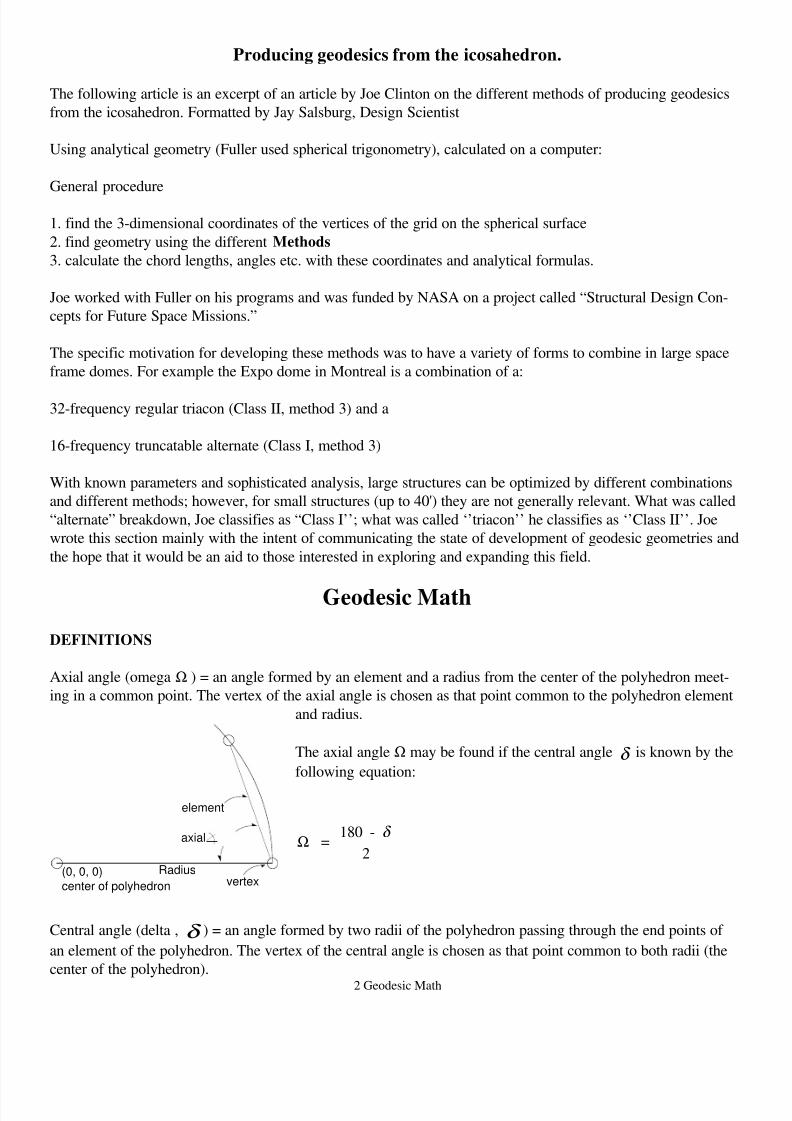
Producing geodesics from the icosahedron.
The following article is an excerpt of an article by Joe Clinton on the different methods of producing geodesics
from the icosahedron. Formatted by Jay Salsburg, Design Scientist
Using analytical geometry (Fuller used spherical trigonometry), calculated on a computer:
General procedure
1. find the 3-dimensional coordinates of the vertices of the grid on the spherical surface
2. find geometry using the different Methods
3. calculate the chord lengths, angles etc. with these coordinates and analytical formulas.
Joe worked with Fuller on his programs and was funded by NASA on a project called “Structural Design Con-
cepts for Future Space Missions.”
The specific motivation for developing these methods was to have a variety of forms to combine in large space
frame domes. For example the Expo dome in Montreal is a combination of a:
32-frequency regular triacon (Class II, method 3) and a
16-frequency truncatable alternate (Class I, method 3)
With known parameters and sophisticated analysis, large structures can be optimized by different combinations
and different methods; however, for small structures (up to 40') they are not generally relevant. What was called
“alternate” breakdown, Joe classifies as “Class I’’; what was called ‘’triacon’’ he classifies as ‘’Class II’’. Joe
wrote this section mainly with the intent of communicating the state of development of geodesic geometries and
the hope that it would be an aid to those interested in exploring and expanding this field.
Geodesic Math
DEFINITIONS
Axial angle (omega Ω ) = an angle formed by an element and a radius from the center of the polyhedron meet-
ing in a common point. The vertex of the axial angle is chosen as that point common to the polyhedron element
and radius.
The axial angle Ω may be found if the central angle δ is known by the
following equation:
Ω =180 -
2
δ
Central angle (delta , δ ) = an angle formed by two radii of the polyhedron passing through the end points of
an element of the polyhedron. The vertex of the central angle is chosen as that point common to both radii (the
center of the polyhedron).
Radius
axial Ω
element
(0, 0, 0)
center of polyhedron vertex
8/6/2019 Geodesic Math
http://slidepdf.com/reader/full/geodesic-math 3/21
3 Geodesic Math
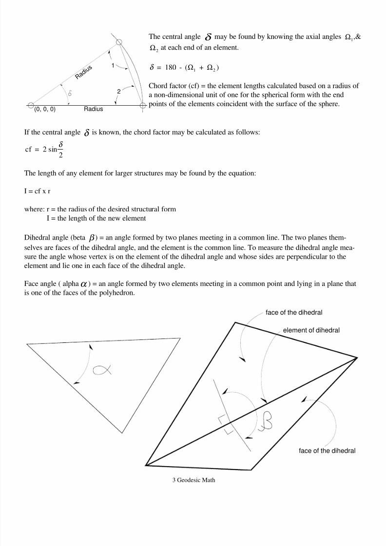
The central angle δ may be found by knowing the axial angles Ω1,&
Ω2at each end of an element.
δ = 180 - ( +1 2Ω Ω )
Chord factor (cf) = the element lengths calculated based on a radius of
a non-dimensional unit of one for the spherical form with the endpoints of the elements coincident with the surface of the sphere.
If the central angle δ is known, the chord factor may be calculated as follows:
cf = 2 sin2
δ
The length of any element for larger structures may be found by the equation:
I = cf x r
where: r = the radius of the desired structural form
I = the length of the new element
Dihedral angle (beta β ) = an angle formed by two planes meeting in a common line. The two planes them-
selves are faces of the dihedral angle, and the element is the common line. To measure the dihedral angle mea-
sure the angle whose vertex is on the element of the dihedral angle and whose sides are perpendicular to the
element and lie one in each face of the dihedral angle.
Face angle ( alphaα
) = an angle formed by two elements meeting in a common point and lying in a plane thatis one of the faces of the polyhedron.
Radius
Ω
R a d i u
s
(0, 0, 0)
2
Ω 1
face of the dihedral
face of the dihedral
element of dihedral
8/6/2019 Geodesic Math
http://slidepdf.com/reader/full/geodesic-math 4/21
4 Geodesic Math
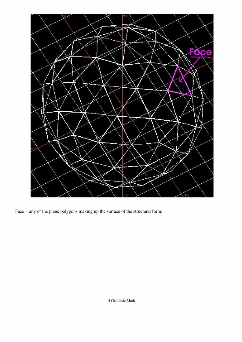
Face = any of the plane polygons making up the surface of the structural form.
8/6/2019 Geodesic Math
http://slidepdf.com/reader/full/geodesic-math 5/21
5 Geodesic Math
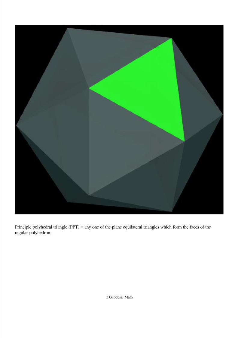
Principle polyhedral triangle (PPT) = any one of the plane equilateral triangles which form the faces of the
regular polyhedron.
8/6/2019 Geodesic Math
http://slidepdf.com/reader/full/geodesic-math 6/21
6 Geodesic Math
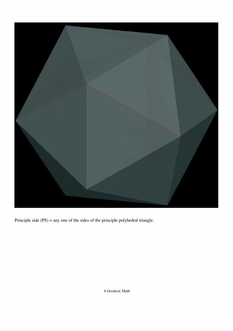
Principle side (PS) = any one of the sides of the principle polyhedral triangle.
8/6/2019 Geodesic Math
http://slidepdf.com/reader/full/geodesic-math 7/21
7 Geodesic Math
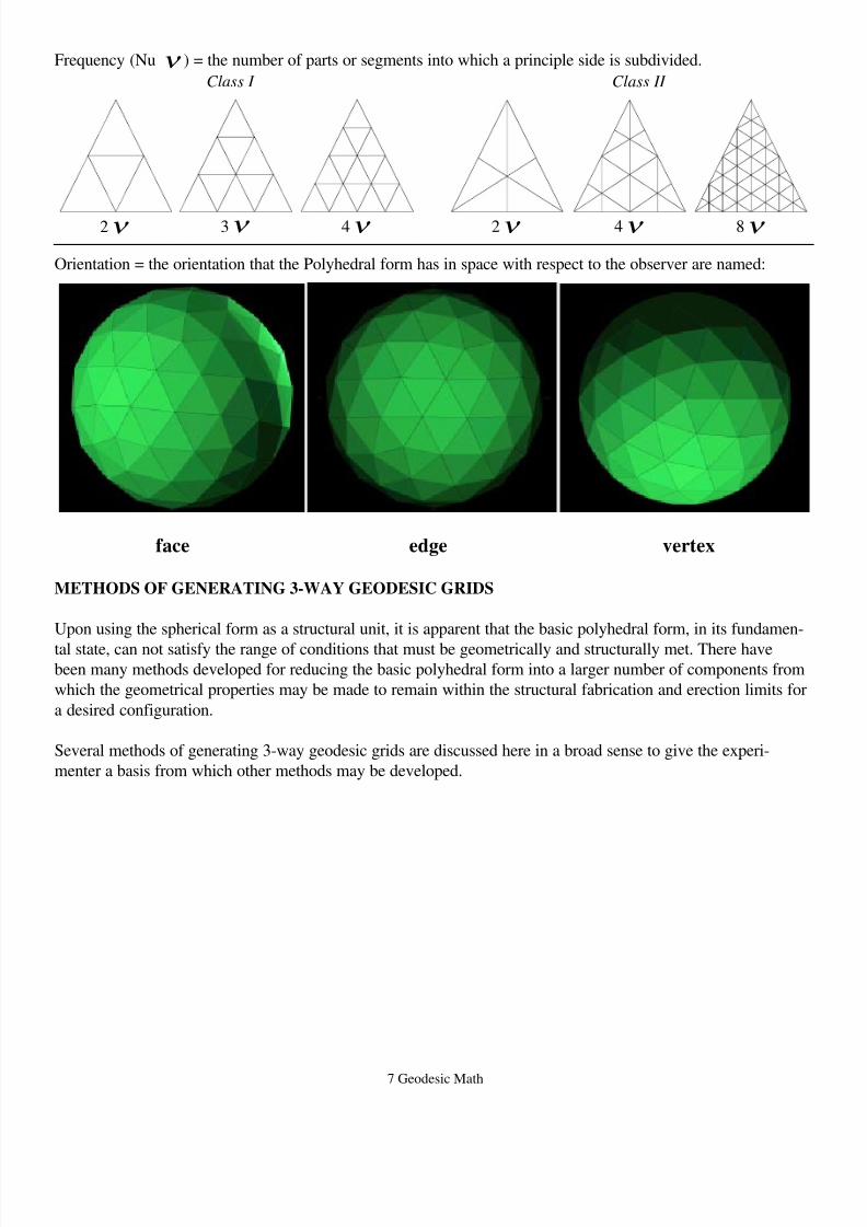
Frequency (Nu ν ) = the number of parts or segments into which a principle side is subdivided.
Class I Class II
Orientation = the orientation that the Polyhedral form has in space with respect to the observer are named:
face edge vertex
METHODS OF GENERATING 3-WAY GEODESIC GRIDS
Upon using the spherical form as a structural unit, it is apparent that the basic polyhedral form, in its fundamen-
tal state, can not satisfy the range of conditions that must be geometrically and structurally met. There havebeen many methods developed for reducing the basic polyhedral form into a larger number of components from
which the geometrical properties may be made to remain within the structural fabrication and erection limits for
a desired configuration.
Several methods of generating 3-way geodesic grids are discussed here in a broad sense to give the experi-
menter a basis from which other methods may be developed.
2ν 3ν 4ν 2ν 4ν 8ν
8/6/2019 Geodesic Math
http://slidepdf.com/reader/full/geodesic-math 8/21
8 Geodesic Math
The methods described here may be considered as having characteristics of one of the two following classifica-
tions:
Class 1 or alternate
- based on regular polyhedral forms, most generally the icosahedron.
- frequency of subdivision may be odd or even.
V = 10 + 2
F = 20
E = 30
2
2
2
ν
ν
ν
where:
V = the number of vertices
F = the number of faces
E = the number of edges
for total icosahedral sphere
= frequency of subdivision
ν
-demonstrates symmetries as illustrated here:
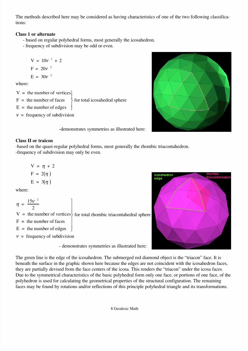
Class II or traicon
-based on the quasi-regular polyhedral forms, most generally the rhombic triacontahedron.
-frequency of subdivision may only be even.
V = + 2
F = 2
E = 3
η
η
η
( )
( )where:
ην
ν
=15
2
V = the number of vertices
F = the number of faces
E = the number of edges
for total rhombic triacontahedral sphere
= frequency of subdivision
2
- demonstrates symmetries as illustrated here:
The green line is the edge of the icosahedron. The submerged red diamond object is the “triacon” face. It is
beneath the surface in the graphic shown here because the edges are not coincident with the icosahedron faces,
they are partially devised from the face centers of the icosa. This renders the “triacon” under the icosa faces.
Due to the symmetrical characteristics of the basic polyhedral form only one face, or portions of one face, of the
polyhedron is used for calculating the geometrical properties of the structural configuration. The remaining
faces may be found by rotations and/or reflections of this principle polyhedral triangle and its transformations.
8/6/2019 Geodesic Math
http://slidepdf.com/reader/full/geodesic-math 9/21
9 Geodesic Math
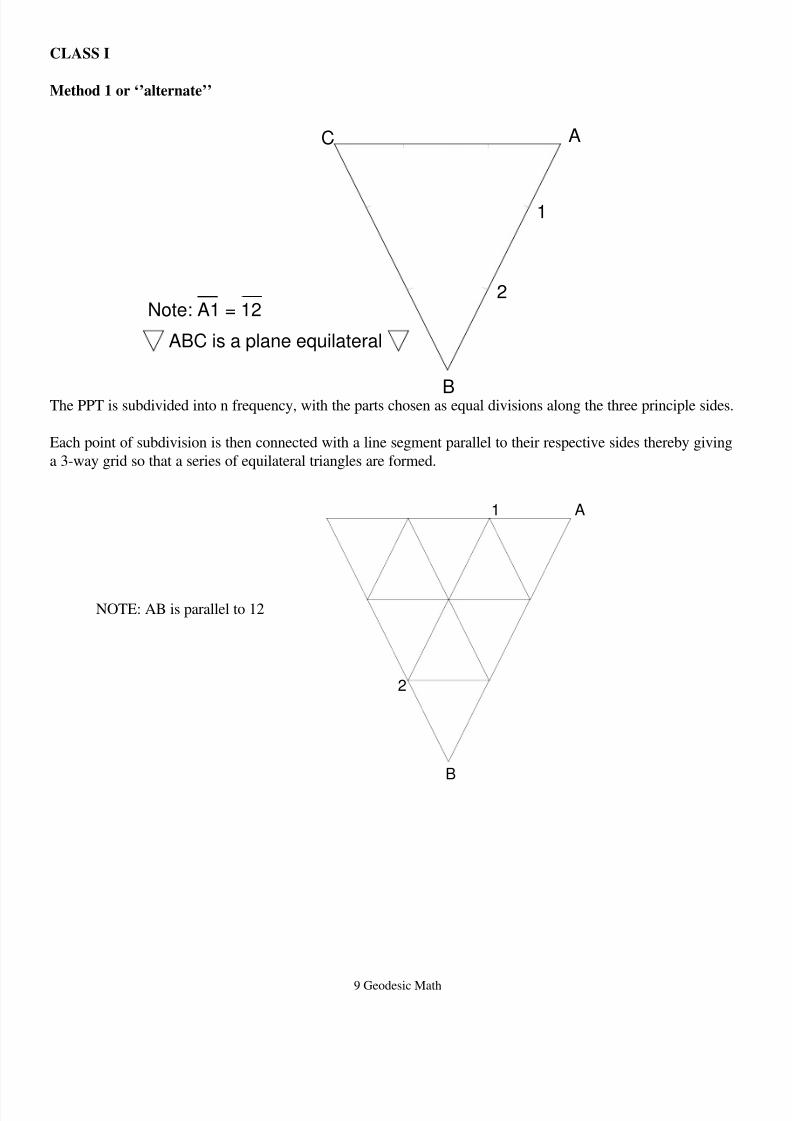
CLASS I
Method 1 or ‘’alternate’’
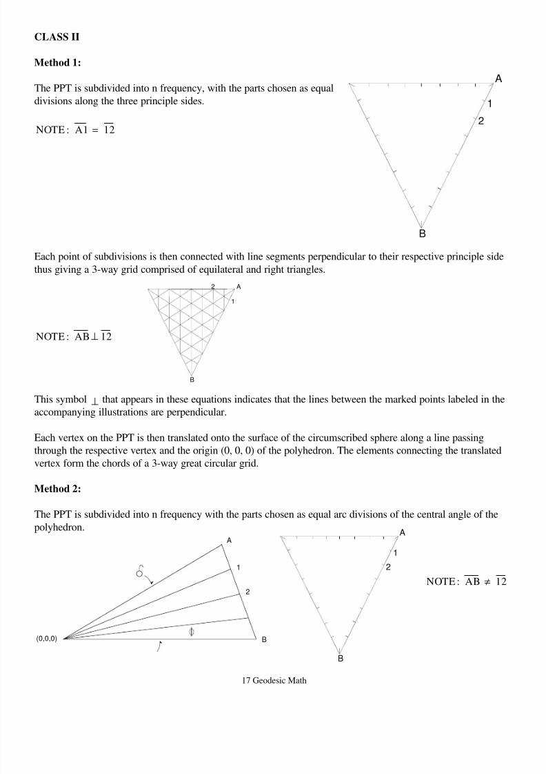
The PPT is subdivided into n frequency, with the parts chosen as equal divisions along the three principle sides.
Each point of subdivision is then connected with a line segment parallel to their respective sides thereby giving
a 3-way grid so that a series of equilateral triangles are formed.
NOTE: AB is parallel to 12
A
B
C
Note: A1 = 12
ABC is a plane equilateral
1
2
A
B
2
1
8/6/2019 Geodesic Math
http://slidepdf.com/reader/full/geodesic-math 10/21
10 Geodesic Math
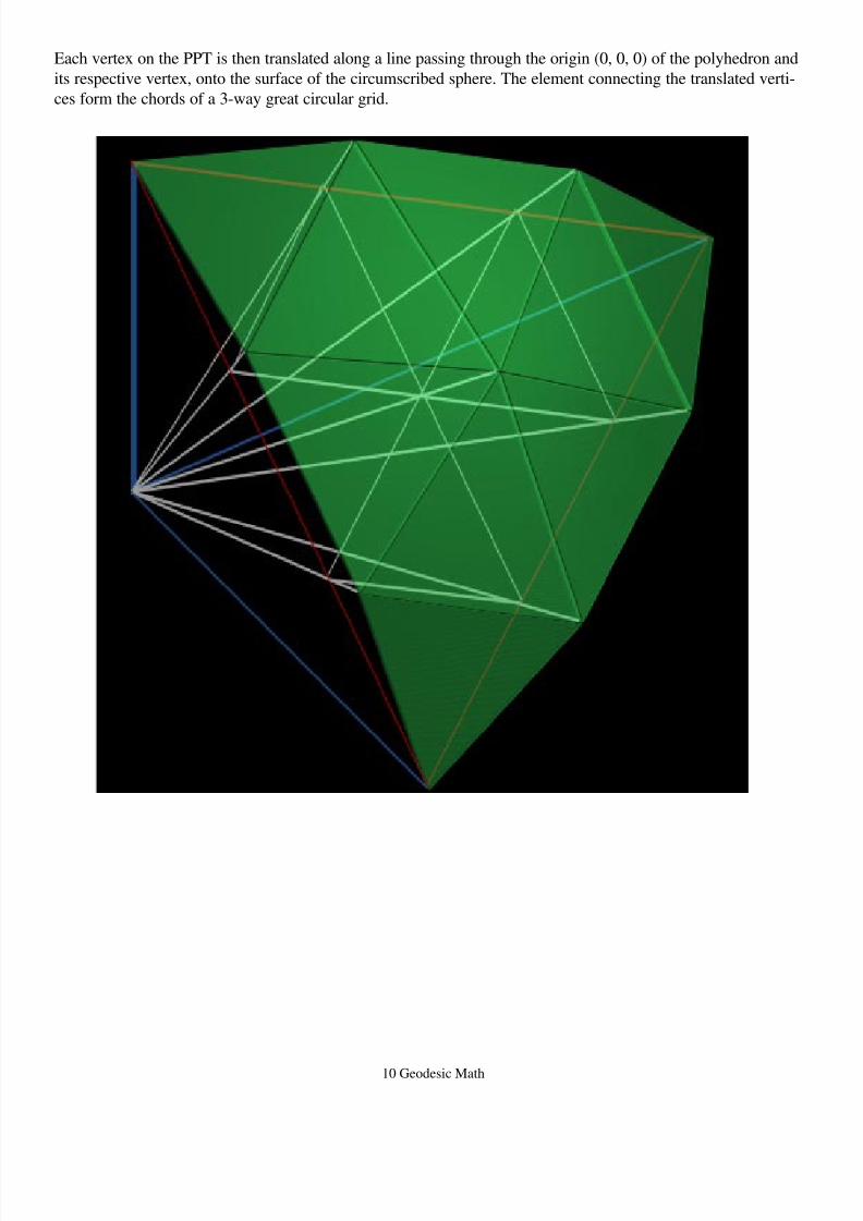
Each vertex on the PPT is then translated along a line passing through the origin (0, 0, 0) of the polyhedron and
its respective vertex, onto the surface of the circumscribed sphere. The element connecting the translated verti-
ces form the chords of a 3-way great circular grid.
8/6/2019 Geodesic Math
http://slidepdf.com/reader/full/geodesic-math 11/21
11 Geodesic Math
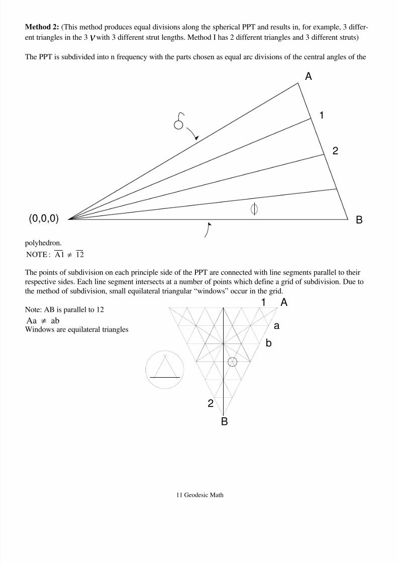
Method 2: (This method produces equal divisions along the spherical PPT and results in, for example, 3 differ-
ent triangles in the 3ν with 3 different strut lengths. Method I has 2 different triangles and 3 different struts)
The PPT is subdivided into n frequency with the parts chosen as equal arc divisions of the central angles of the
polyhedron.
NOTE : A1 12≠
The points of subdivision on each principle side of the PPT are connected with line segments parallel to their
respective sides. Each line segment intersects at a number of points which define a grid of subdivision. Due to
the method of subdivision, small equilateral triangular “windows” occur in the grid.
Note: AB is parallel to 12
Aa ab≠
Windows are equilateral triangles
A
a
b
B
2
1
(0,0,0)
A
B
1
2
8/6/2019 Geodesic Math
http://slidepdf.com/reader/full/geodesic-math 12/21
12 Geodesic Math
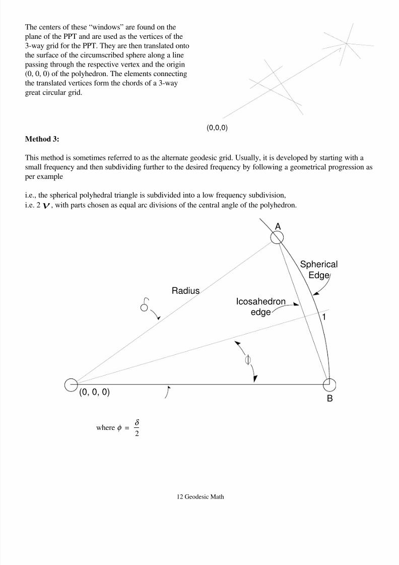
The centers of these “windows” are found on the
plane of the PPT and are used as the vertices of the
3-way grid for the PPT. They are then translated onto
the surface of the circumscribed sphere along a line
passing through the respective vertex and the origin
(0, 0, 0) of the polyhedron. The elements connecting
the translated vertices form the chords of a 3-way
great circular grid.
Method 3:
This method is sometimes referred to as the alternate geodesic grid. Usually, it is developed by starting with a
small frequency and then subdividing further to the desired frequency by following a geometrical progression as
per example
i.e., the spherical polyhedral triangle is subdivided into a low frequency subdivision,i.e. 2ν , with parts chosen as equal arc divisions of the central angle of the polyhedron.
where =2
φ δ
(0,0,0)
RadiusIcosahedron
edge
(0, 0, 0) B
A
1
Spherical
Edge
8/6/2019 Geodesic Math
http://slidepdf.com/reader/full/geodesic-math 13/21
13 Geodesic Math
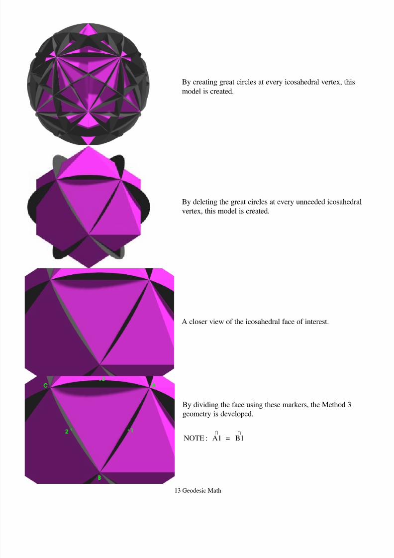
By creating great circles at every icosahedral vertex, this
model is created.
By deleting the great circles at every unneeded icosahedral
vertex, this model is created.
A closer view of the icosahedral face of interest.
By dividing the face using these markers, the Method 3
geometry is developed.
NOTE : A1 = B1I I
8/6/2019 Geodesic Math
http://slidepdf.com/reader/full/geodesic-math 14/21
14 Geodesic Math
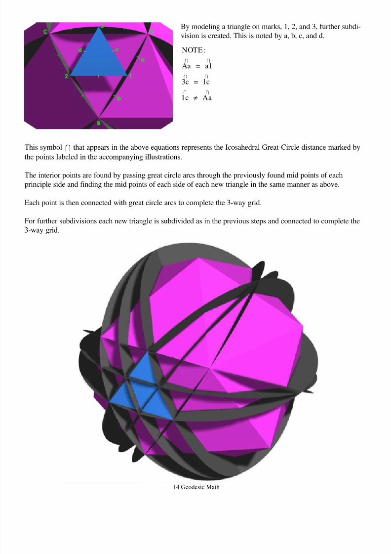
By modeling a triangle on marks, 1, 2, and 3, further subdi-
vision is created. This is noted by a, b, c, and d.
NOTE :
Aa = a1
3c = 1c
1c Aa
I I
I I
I I
≠
This symbol I that appears in the above equations represents the Icosahedral Great-Circle distance marked by
the points labeled in the accompanying illustrations.
The interior points are found by passing great circle arcs through the previously found mid points of each
principle side and finding the mid points of each side of each new triangle in the same manner as above.
Each point is then connected with great circle arcs to complete the 3-way grid.
For further subdivisions each new triangle is subdivided as in the previous steps and connected to complete the
3-way grid.
8/6/2019 Geodesic Math
http://slidepdf.com/reader/full/geodesic-math 15/21
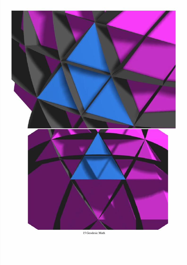
15 Geodesic Math
8/6/2019 Geodesic Math
http://slidepdf.com/reader/full/geodesic-math 16/21
16 Geodesic Math
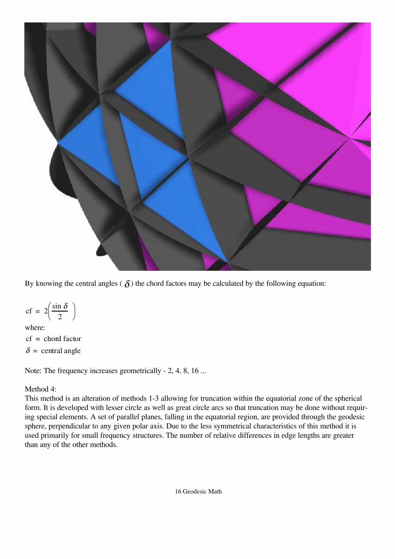
By knowing the central angles (δ ) the chord factors may be calculated by the following equation:
cf = 2sin
2
δ
where:
cf = chord factor
= central angleδ
Note: The frequency increases geometrically - 2, 4, 8, 16 ...
Method 4:This method is an alteration of methods 1-3 allowing for truncation within the equatorial zone of the spherical
form. It is developed with lesser circle as well as great circle arcs so that truncation may be done without requir-
ing special elements. A set of parallel planes, falling in the equatorial region, are provided through the geodesic
sphere, perpendicular to any given polar axis. Due to the less symmetrical characteristics of this method it is
used primarily for small frequency structures. The number of relative differences in edge lengths are greater
than any of the other methods.
8/6/2019 Geodesic Math
http://slidepdf.com/reader/full/geodesic-math 17/21
8/6/2019 Geodesic Math
http://slidepdf.com/reader/full/geodesic-math 18/21
18 Geodesic Math
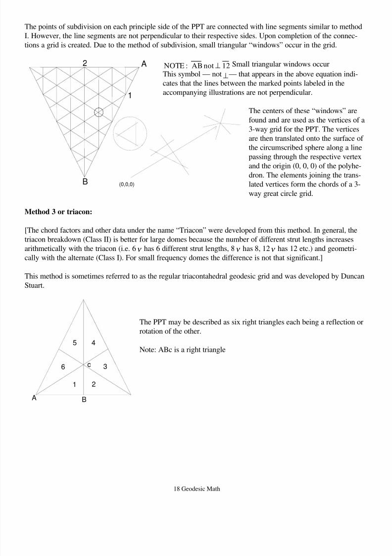
The points of subdivision on each principle side of the PPT are connected with line segments similar to method
I. However, the line segments are not perpendicular to their respective sides. Upon completion of the connec-
tions a grid is created. Due to the method of subdivision, small triangular “windows” occur in the grid.
NOTE : AB not 12⊥ Small triangular windows occur
This symbol — not⊥— that appears in the above equation indi-
cates that the lines between the marked points labeled in the
accompanying illustrations are not perpendicular.
The centers of these “windows” are
found and are used as the vertices of a
3-way grid for the PPT. The vertices
are then translated onto the surface of
the circumscribed sphere along a line
passing through the respective vertex
and the origin (0, 0, 0) of the polyhe-
dron. The elements joining the trans-
lated vertices form the chords of a 3-
way great circle grid.
Method 3 or triacon:
[The chord factors and other data under the name “Triacon” were developed from this method. In general, the
triacon breakdown (Class II) is better for large domes because the number of different strut lengths increases
arithmetically with the triacon (i.e. 6ν has 6 different strut lengths, 8ν has 8, 12ν has 12 etc.) and geometri-
cally with the alternate (Class I). For small frequency domes the difference is not that significant.]
This method is sometimes referred to as the regular triacontahedral geodesic grid and was developed by Duncan
Stuart.
The PPT may be described as six right triangles each being a reflection or
rotation of the other.
Note: ABc is a right triangle
(0,0,0)
A
1
2
B
A B
1 2
3
45
6 c
8/6/2019 Geodesic Math
http://slidepdf.com/reader/full/geodesic-math 19/21
19 Geodesic Math
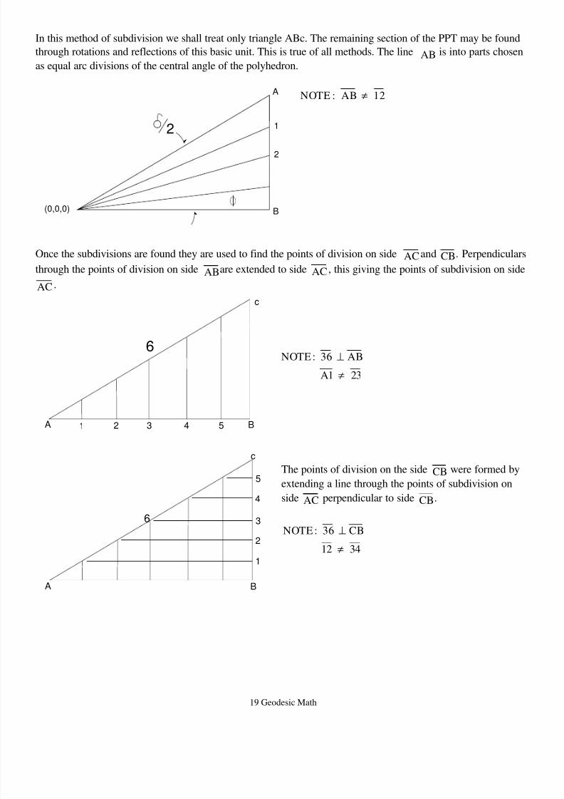
In this method of subdivision we shall treat only triangle ABc. The remaining section of the PPT may be found
through rotations and reflections of this basic unit. This is true of all methods. The line AB is into parts chosen
as equal arc divisions of the central angle of the polyhedron.
NOTE : AB 12≠
Once the subdivisions are found they are used to find the points of division on side ACand CB. Perpendiculars
through the points of division on side ABare extended to side AC , this giving the points of subdivision on side
AC .
NOTE : 36 AB
A1 23
⊥
≠
The points of division on the side CB were formed by
extending a line through the points of subdivision on
side AC perpendicular to side CB.
NOTE : 36 CB
12 34
⊥
≠
(0,0,0)
A
B
1
2
2
A B1 2
6
3 4 5
c
A B
1
2
6 3
4
5
c
8/6/2019 Geodesic Math
http://slidepdf.com/reader/full/geodesic-math 20/21
20 Geodesic Math
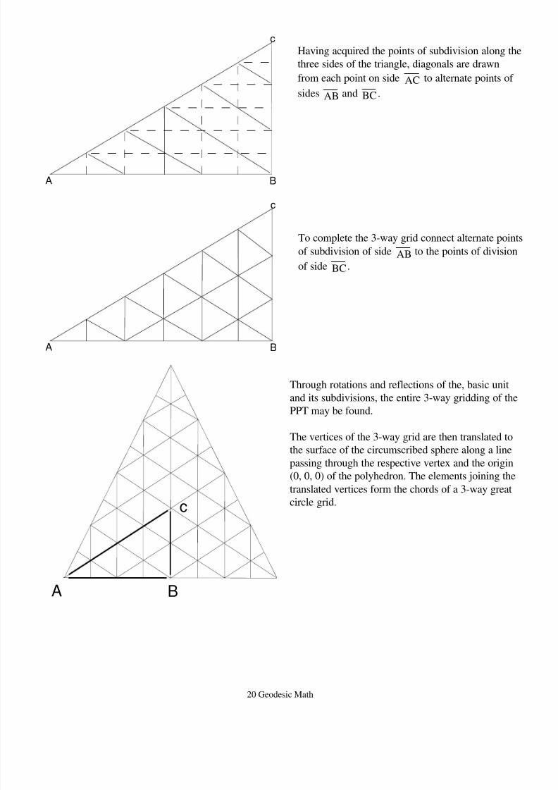
Having acquired the points of subdivision along the
three sides of the triangle, diagonals are drawn
from each point on side AC to alternate points of
sides AB and BC .
To complete the 3-way grid connect alternate points
of subdivision of side AB to the points of division
of side BC .
Through rotations and reflections of the, basic unit
and its subdivisions, the entire 3-way gridding of the
PPT may be found.
The vertices of the 3-way grid are then translated to
the surface of the circumscribed sphere along a line
passing through the respective vertex and the origin
(0, 0, 0) of the polyhedron. The elements joining the
translated vertices form the chords of a 3-way great
circle grid.
A B
c
A B
c
A B
c
8/6/2019 Geodesic Math
http://slidepdf.com/reader/full/geodesic-math 21/21
Method 4:
[This method is basically the same as method 3 except that instead of dividing side AB of the right triangle
with the equal arc divisions, side AC is divided. The rest of the procedure is the same, given the new starting
point.]
All Artwork, Graphics and Illustrations were created or made by Jay Salsburg, Design Scientist,