Embed Size (px)
Citation preview
Geographical Versus Functional Modelling by
Statecharts of Interlocking Systems
Michele Banci1
Formal Methods and Tools GroupISTI - CNRPisa, Italy
Alessandro Fantechi2
Dipartimento di Sistemi e InformaticaUniversita degli Studi di Firenze
Firenze, Italy
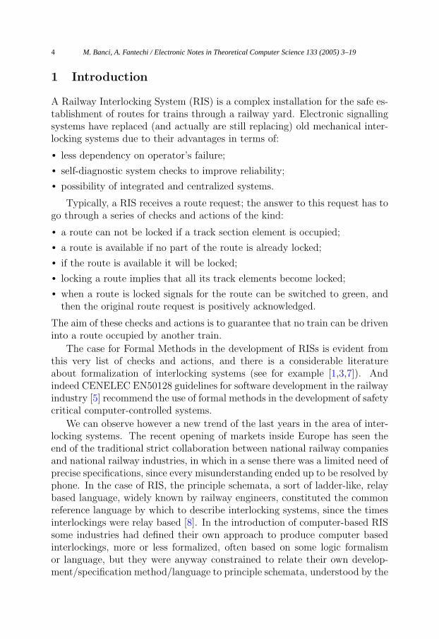
Abstract
The development of computer controlled Railway Interlocking Systems (RIS) has seen an increasinginterest in the use of Formal Methods, due to their ability to precisely specify the logical rules thatguarantee the safe establishment of routes for trains through a railway yard.Recently, a trend has emerged about the use of statecharts as a standard formalism to produceprecise specifications of RIS. This paper describes an experience in modelling a railway interlockingsystem using statecharts. Our study has addressed the problem from a “geographical”, distributed,point of view: that is, our model is composed by models of single physical entities (points, signals,etc..) that collectively implement the interlocking rules, without any centralized database of rules,which is on the other hand a typical way of implementing such a system (what we call “functional”approach).One of the main aims of our approach, is to verify its ability to reduce revalidation efforts in thecase of physical modifications to the yard; we show how the geographical approach may reduce thiseffort by requiring only the revalidation of those software modules that are actually affected by thechanges.
Keywords: Railway signalling, interlocking, safety-critical systems, formal specification,Statecharts, validation.
1 Email: [email protected] Email: [email protected]
Electronic Notes in Theoretical Computer Science 133 (2005) 3–19
1571-0661 © 2005 Elsevier B.V. Open access under CC BY-NC-ND license.
www.elsevier.com/locate/entcs
doi:10.1016/j.entcs.2004.08.055
1 Introduction
A Railway Interlocking System (RIS) is a complex installation for the safe es-tablishment of routes for trains through a railway yard. Electronic signallingsystems have replaced (and actually are still replacing) old mechanical inter-locking systems due to their advantages in terms of:
• less dependency on operator’s failure;
• self-diagnostic system checks to improve reliability;
• possibility of integrated and centralized systems.
Typically, a RIS receives a route request; the answer to this request has togo through a series of checks and actions of the kind:
• a route can not be locked if a track section element is occupied;
• a route is available if no part of the route is already locked;
• if the route is available it will be locked;
• locking a route implies that all its track elements become locked;
• when a route is locked signals for the route can be switched to green, andthen the original route request is positively acknowledged.
The aim of these checks and actions is to guarantee that no train can be driveninto a route occupied by another train.
The case for Formal Methods in the development of RISs is evident fromthis very list of checks and actions, and there is a considerable literatureabout formalization of interlocking systems (see for example [1,3,7]). Andindeed CENELEC EN50128 guidelines for software development in the railwayindustry [5] recommend the use of formal methods in the development of safetycritical computer-controlled systems.
We can observe however a new trend of the last years in the area of inter-locking systems. The recent opening of markets inside Europe has seen theend of the traditional strict collaboration between national railway companiesand national railway industries, in which in a sense there was a limited need ofprecise specifications, since every misunderstanding ended up to be resolved byphone. In the case of RIS, the principle schemata, a sort of ladder-like, relaybased language, widely known by railway engineers, constituted the commonreference language by which to describe interlocking systems, since the timesinterlockings were relay based [8]. In the introduction of computer-based RISsome industries had defined their own approach to produce computer basedinterlockings, more or less formalized, often based on some logic formalismor language, but they were anyway constrained to relate their own develop-ment/specification method/language to principle schemata, understood by the
M. Banci, A. Fantechi / Electronic Notes in Theoretical Computer Science 133 (2005) 3–194
national company signalling engineers.
On the other hand, the open, less protected markets have brought to the re-organization and merging of the previous national industries into a few multi-national companies, which need now to merge different know-hows about in-terlocking production.
In an open market, greater reliance has to be put on precise contractualspecifications to define the responsibility of each involved party; moreover,the multinational dimensions of railway industries asks for a standardizationof the interlocking systems, and of their contractual specifications, in orderto propose the same product to several companies Europe-wide. The Euroin-terlocking project has been launched by a consortium of the main Europeanrailway companies, with the aim of developing a standard interlocking systemat a European level, in order to decrease investment and maintenance costsfor companies, thanks to standardization.
Inside this project a trend has developed towards the use of finite statemachines for modelling interlocking rules [15]. In particular, a richer formof machines, namely the Statecharts [9,11], has been considered suitable toexpress the sequences of checks and actions typical of an interlocking system.Both the UML dialect [16] and the Statemate dialect [12] of Statecharts havebeen considered.
This paper follows this trend, describing an experience of modelling arailway interlocking system using Statecharts. Our study has addressed theproblem from a “geographical”, distributed, point of view, rather than a “func-tional”, centralized, point of view: that is, our model is made up by modelsof single physical entities (points, signals, etc..) that collectively implementthe interlocking rules, without any centralized database of rules, which is atypical way of approaching the problem, that we call “functional” approach.
The main aim of this study is to investigate the feasibility of the geo-graphical approach, and to compare it to the functional one; one of the mostinteresting issues we are interested in evaluating, and which has actually moti-vated our work, is to verify the ability of the geographical approach to reducerevalidation efforts in the case of physical modifications to the yard: indeedoften a small change of the physical configuration of the yard requires, in orderto comply to the strict guidelines for safety, a complete new validation effort,e.g. by an extensive testing program, due to the changes done to a singlecentral structure used by all the software modules. We show how the geo-graphical approach may reduce this effort by allowing the re-validation onlyof those software modules that are actually affected by the changes.
M. Banci, A. Fantechi / Electronic Notes in Theoretical Computer Science 133 (2005) 3–19 5
2 Geographical and functional modelling
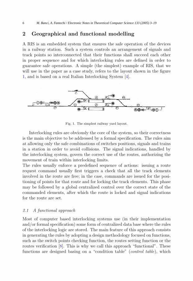
A RIS is an embedded system that ensures the safe operation of the devicesin a railway station. Such a system controls an arrangement of signals andtrack points so interconnected that their functions shall succeed each otherin proper sequence and for which interlocking rules are defined in order toguarantee safe operations. A simple (the simplest) example of RIS, that wewill use in the paper as a case study, refers to the layout shown in the figure1, and is based on a real Italian Interlocking System [4].
Fig. 1. The simplest railway yard layout.
Interlocking rules are obviously the core of the system, so their correctnessis the main objective to be addressed by a formal specification. The rules aimat allowing only the safe combinations of switches positions, signals and trainsin a station in order to avoid collisions. The signal indications, handled bythe interlocking system, govern the correct use of the routes, authorizing themovement of train within interlocking limits.The rules usually enforce a predefined sequence of actions: issuing a routerequest command usually first triggers a check that all the track elementsinvolved in the route are free; in the case, commands are issued for the posi-tioning of points for that route and for locking the track elements. This phasemay be followed by a global centralized control over the correct state of thecommanded elements, after which the route is locked and signal indicationsfor the route are set.
2.1 A functional approach
Most of computer based interlocking systems use (in their implementationand/or formal specification) some form of centralized data base where the rulesof the interlocking logic are stored. The main feature of this approach consistsin generating the rules by adopting a design methodology focused on functions,such as the switch points checking function, the routes setting function or theroutes verification [8]. This is why we call this approach “functional”. Thesefunctions are designed basing on a “condition table” (control table), which
M. Banci, A. Fantechi / Electronic Notes in Theoretical Computer Science 133 (2005) 3–196
indicates all of the conditions that have to be satisfied before a signal can beswitched from red to green to admit a train into the track section beyond [14].The placement of the yard equipments is ignored in this design methodology,it does not exist a direct correlation between the geographical position on theyard of a device and the function that controls it implemented in the RIS. Forthis reason it is a hard task to identify the parts of the system stimulated byexternal events.
2.2 A geographical approach
A different approach can consider distributing the knowledge of the interlock-ing rules to objects modelling the geographical placement of physical elements.
An example of geographical specification is the EURIS language (EUro-pean Railway Interlocking Specification), which is a visual and graphical spec-ification language for railway control systems [2,6]. Using this language it ispossible to build in a component-based way the control system from the lay-out of the station to model. The EURIS specification language, proposedin 1992 and used at Siemens, is used to specify different railway yards usingthe same generical specification components. Actually it consists of a set ofstandardized railway control components [18], which should be composed to-gether easily, increasing the speed of development and permitting the reuseof components. Each element includes a set of rules inside it, which are ableto adjust to different layout configurations. Because EURIS is a graphicallanguage another advantage is that specifications are easy to read, since theyimmediately represent the physical position of elements in the yard.
2.3 Revalidation
At first sight it could seem that the layout of a railway yard is fixed and cannotbe changed. Actually, the layout can be changed during construction worksto enable partial operation of the yard, or after for maintenance works, or forextensions. This may happen several times in the lifetime of an interlockingsystem, which anyway spans several decades. Computer based RIS have theobvious advantage over relay-based ones that any change can be addressedby a change in the software. However, the strict guidelines followed in thedevelopment of this piece of safety critical software require a costly validationactivity: any change to the software requires a revalidation activity as well.The adoption of methods and techniques that can reduce such efforts andcosts is therefore an important industrial objective.In this paper we study the impact that a geographical approach to the speci-fication of a RIS can have on this particular aspect: the idea is that changing
M. Banci, A. Fantechi / Electronic Notes in Theoretical Computer Science 133 (2005) 3–19 7
a part of the layout affects only those software objects that are geographi-cally close to the changed ones. Only the affected ones need therefore to berevalidated.
3 Statecharts
The Statecharts formalism [9] is an extension of the classic formalism of FiniteState Machines (FSM), to allow hierarchical parallel interacting state machinesto be specified. Transition from a state to another of a single machine (astatechart) is driven by trigger events, which can refer to the state of othermachines or to global variables; therefore, the communication activity betweenstatecharts is performed using broadcasting: every event is sent to the wholesystem, and can be received from any other part of the system. During atransition the actions generate events, which are triggered by conditions onother transitions or on global variables. Chains of internal events generatedby only one external event are possible.
The hierarchy features of Statecharts permit to slice a system into welldefined subsystems, so reducing the complexity, and permitting to build astructured model with concurrent parts. The system can be decomposed usingAND-states, which evolve singularly and in a parallel way.
Two main dialects of Statecharts are actually used: UML (Unified Mod-elling Language) State Diagrams [16] and Statemate Statecharts [10].
3.1 The Statemate tool
In this paper, we follow the style of Statemate Statecharts. The I-Logix State-mate tool [17,13] supports the editing of the graphical Statecharts notation,but more importantly allows the complete system specification to be executedand graphically simulated, permitting to explore any scenarios determiningthe system correctness, and evaluating whether the specification meets therequirements.
The Statemate simulator allows to execute the model, permitting to verifythe behavior examining the animation of the system. Furthermore it allowsto animate panels to have an evidence of the model behavior, so that we cangenerate easily “what-if” scenarios. Statemate provides also the automaticgeneration of a C-based or Ada-based prototyping source code based on themodel. Another important recent add-on to Statemate (which we have notused in this experience so far) is a powerful model checker, which is obvi-ously an advantage in terms of the confidence that can be acquired on thespecification correctness.
M. Banci, A. Fantechi / Electronic Notes in Theoretical Computer Science 133 (2005) 3–198
These features of Statemate make it currently superior w.r.t. UML-basedtools which allows only editing of State Diagrams [7].
The Statemate tool supports also another sort of charts, useful to build astructured system: the Activity Chart. Activity charts can be viewed as multi-level (hierarchical) data-flow diagrams (DFD). An activity chart describes thefunctional decomposition of system’s capabilities into functions, or activities,organized into hierarchies. This hierarchy details the functional components,or activities, that the system is capable of carrying out, and how these com-ponents communicate through information flow among them. The behaviorof each activity is described using statecharts. In this study the activities areused to represent the distributed devices on the yard and therefore a control-ling statechart is associated to each device.
These charts are more flexible than the statecharts since they can be ac-tivated and deactivated dynamically, which is not possible with statecharts.Each activity is a subsystem with a proper function, expressed in its turn bystatecharts.
4 Statecharts geographical model
We suggest a way to design an interlocking system starting from its layoutand ending in its operational specification. This approach is similar to theone used in EURIS language [2]. In this work we focus on a methodology thatdoes not use any sort of global summarizing variables, which is usual insteadfor a functional approach.
With the term summarizing variable we mean a variable whose valuesdepend from the values of a set of other single variables, each related toa physical entity of the layout. As an example we can consider a variableassociated to a route, that is true if and only if at least one of the variablesrecording the occupancy of the track circuits belonging to the route is set totrue. The use of summarizing variables, though useful for abstracting certainglobal aspects of the system, makes the model more distant from the physicaltopology.
The experience discussed in this paper has been actually preceded by amodelling by Statemate statecharts of the same interlocking system, using aclassical functional approach: specific modules were dedicated to record com-manded routes; these modules have been given the responsibility of checkingthe occupancy of the interested track circuits, following what prescribed bythe condition table given as input. On the contrary, we will see how in ourpresented approach it is each module dedicated to the management of eachtrack circuit that has the responsibility to check its compatibility with com-
M. Banci, A. Fantechi / Electronic Notes in Theoretical Computer Science 133 (2005) 3–19 9
manded routes. In the same way, all the activities performed by functionalobjects have been distributed to these geographical objects. Hence, the controlfor example of the correct position of a particular switch point is performedfrom all the interested elements and not by a single object dedicated to themanagement of all the switch points.
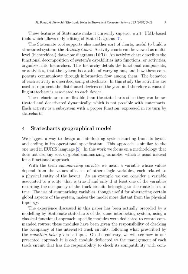
Fig. 2. An example of routing.
Each object of the model implements the rules that interest only that ob-ject. If, for example, we consider the three signals of Figure 2, the model willinclude an object for each semaphore. The object related to the semaphore 4,which permits the movement of a train in the right direction, should controlthat the red lights of semaphores 3 right and 2 left are fired and also thatthe green lights are switched off. This control is done not looking at a globalsummarizing variable which in the example would show that the route is free,but communicating with the objects that control the other semaphores anddevices.
In this way, we obtain a model whose structure reflects the layout of therailway yard. This has positive effects on the readability of the model, and onthe possibility of isolating in the model only those objects that are interestedby a change in the physical layout.
On the other hand, we loose on generality: in the functional approachthe module handling all switch points can be generic, and it is the conditiontable that embeds the knowledge about the specific rules for the railway yard.Our objects have not a generic behavior usable in any different geographicallayout (like EURIS): we have to redesign them for any different station, thoughfollowing expected patterns with predetermined rules.
The consequences of this approach are:
• The structure of the model should reflect the geographical topology of theyard.
• The elements of the model should replicate the behavior of the physical
M. Banci, A. Fantechi / Electronic Notes in Theoretical Computer Science 133 (2005) 3–1910
components of the yard.
• The elements of the model should embed all the logical rules interesting thecorresponding physical components (in order to avoid the usage of summa-rizing variables).
This kind of model is able to minimize the inter-dependency between ob-jects.
Objects cannot be completely independent; in fact an interlocking systemis by definition a system that have to control the interrelations between theobjects. However, a geographical model maximizes independency: where thereis independency in the yard, we want that it is reflected in the model.
4.1 Structure of the layered model
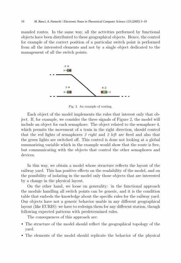
The model is built following a layered architecture for the RIS, which consistsof three layers: Command (human) layer, Logical layer and Physical layer(Figure 3). The first layer (Command) is dedicated to the interaction with
Fig. 3. Illustration of the layered interlocking architecture.
operators or other systems, which send commands to the RIS.
At the lowest level (Physical), there are the yard devices and equipments,which have to be commanded and controlled by the RIS. This level is consti-tuted of the actual device interfaces, with actual variables used to control theyard.The middle level is the core of the RIS, where the interlocking rules are spec-ified. It is formed by a separate object for each physical device.
M. Banci, A. Fantechi / Electronic Notes in Theoretical Computer Science 133 (2005) 3–19 11
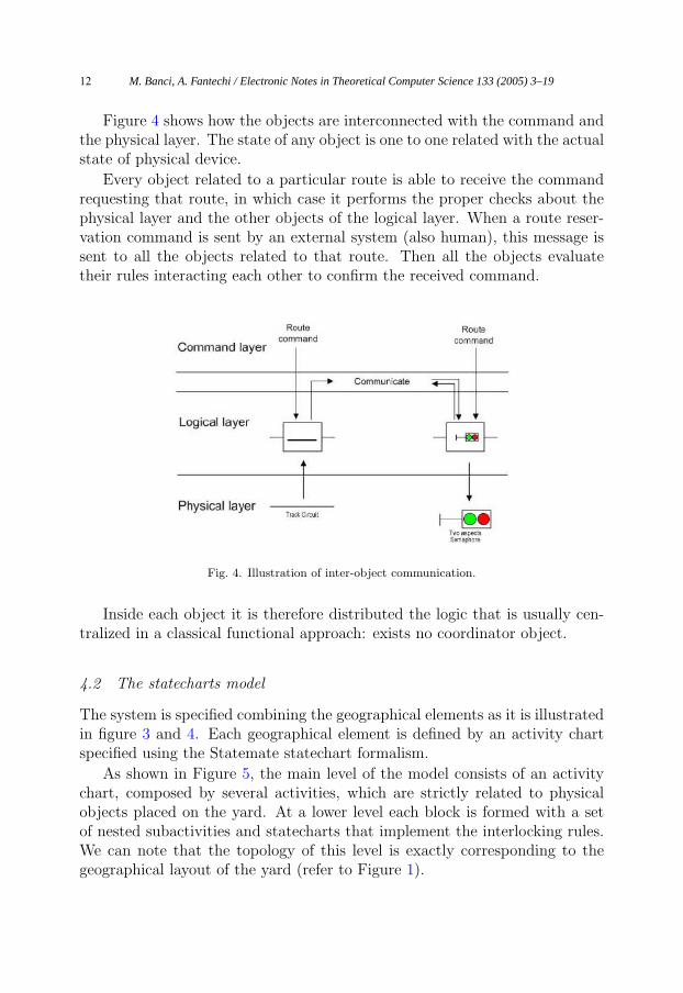
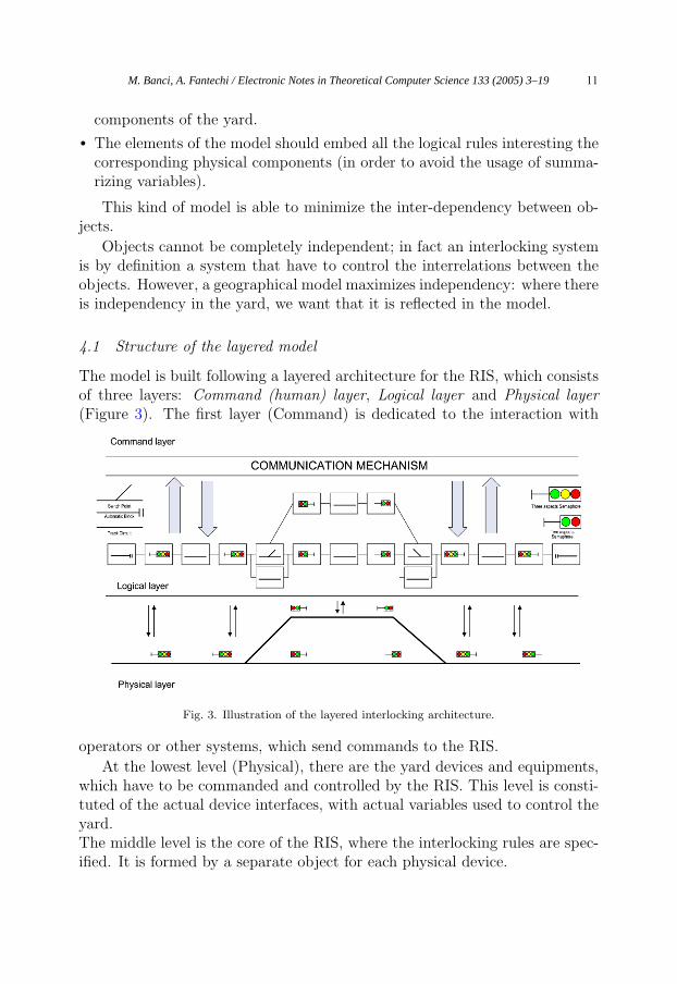
Figure 4 shows how the objects are interconnected with the command andthe physical layer. The state of any object is one to one related with the actualstate of physical device.
Every object related to a particular route is able to receive the commandrequesting that route, in which case it performs the proper checks about thephysical layer and the other objects of the logical layer. When a route reser-vation command is sent by an external system (also human), this message issent to all the objects related to that route. Then all the objects evaluatetheir rules interacting each other to confirm the received command.
Fig. 4. Illustration of inter-object communication.
Inside each object it is therefore distributed the logic that is usually cen-tralized in a classical functional approach: exists no coordinator object.
4.2 The statecharts model
The system is specified combining the geographical elements as it is illustratedin figure 3 and 4. Each geographical element is defined by an activity chartspecified using the Statemate statechart formalism.
As shown in Figure 5, the main level of the model consists of an activitychart, composed by several activities, which are strictly related to physicalobjects placed on the yard. At a lower level each block is formed with a setof nested subactivities and statecharts that implement the interlocking rules.We can note that the topology of this level is exactly corresponding to thegeographical layout of the yard (refer to Figure 1).
M. Banci, A. Fantechi / Electronic Notes in Theoretical Computer Science 133 (2005) 3–1912
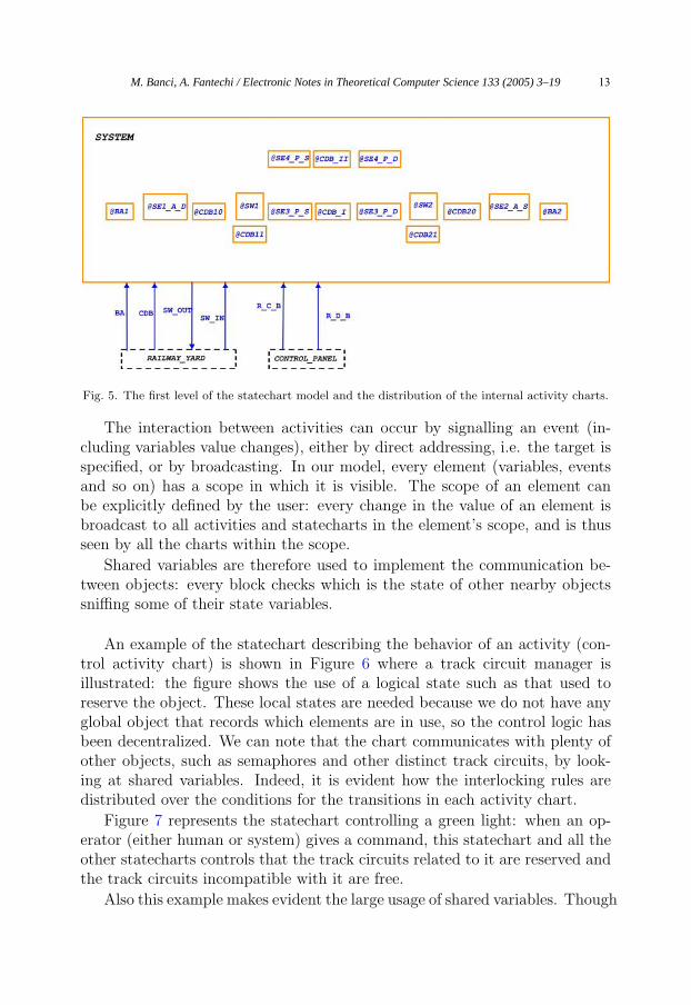
Fig. 5. The first level of the statechart model and the distribution of the internal activity charts.
The interaction between activities can occur by signalling an event (in-cluding variables value changes), either by direct addressing, i.e. the target isspecified, or by broadcasting. In our model, every element (variables, eventsand so on) has a scope in which it is visible. The scope of an element canbe explicitly defined by the user: every change in the value of an element isbroadcast to all activities and statecharts in the element’s scope, and is thusseen by all the charts within the scope.
Shared variables are therefore used to implement the communication be-tween objects: every block checks which is the state of other nearby objectssniffing some of their state variables.
An example of the statechart describing the behavior of an activity (con-trol activity chart) is shown in Figure 6 where a track circuit manager isillustrated: the figure shows the use of a logical state such as that used toreserve the object. These local states are needed because we do not have anyglobal object that records which elements are in use, so the control logic hasbeen decentralized. We can note that the chart communicates with plenty ofother objects, such as semaphores and other distinct track circuits, by look-ing at shared variables. Indeed, it is evident how the interlocking rules aredistributed over the conditions for the transitions in each activity chart.
Figure 7 represents the statechart controlling a green light: when an op-erator (either human or system) gives a command, this statechart and all theother statecharts controls that the track circuits related to it are reserved andthe track circuits incompatible with it are free.
Also this example makes evident the large usage of shared variables. Though
M. Banci, A. Fantechi / Electronic Notes in Theoretical Computer Science 133 (2005) 3–19 13
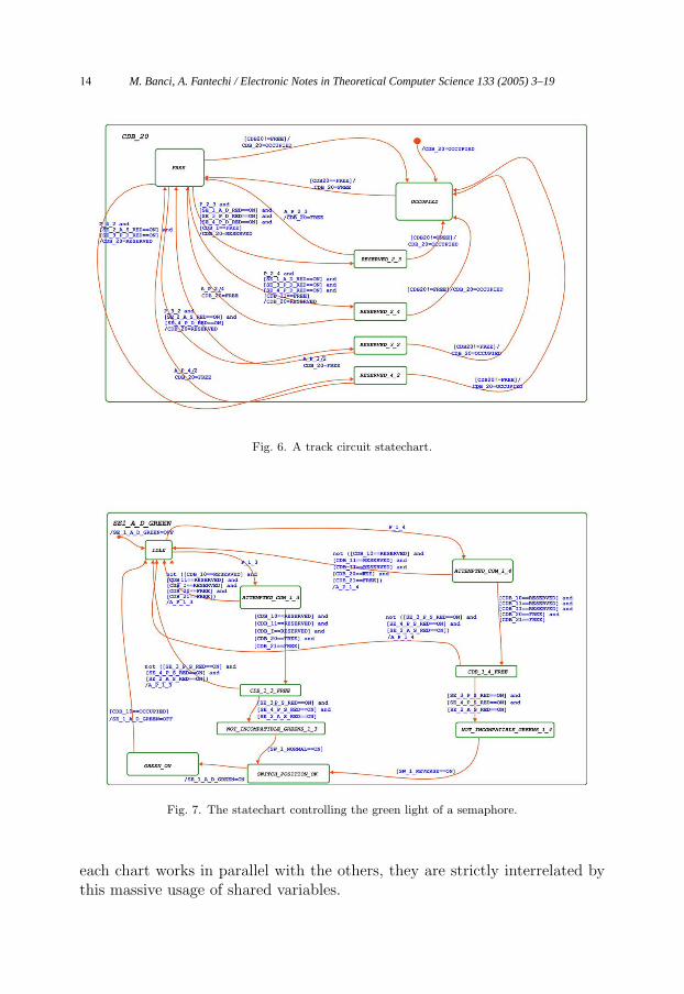
Fig. 6. A track circuit statechart.
Fig. 7. The statechart controlling the green light of a semaphore.
each chart works in parallel with the others, they are strictly interrelated bythis massive usage of shared variables.
M. Banci, A. Fantechi / Electronic Notes in Theoretical Computer Science 133 (2005) 3–1914
5 A comparison between functional and geographicalapproach
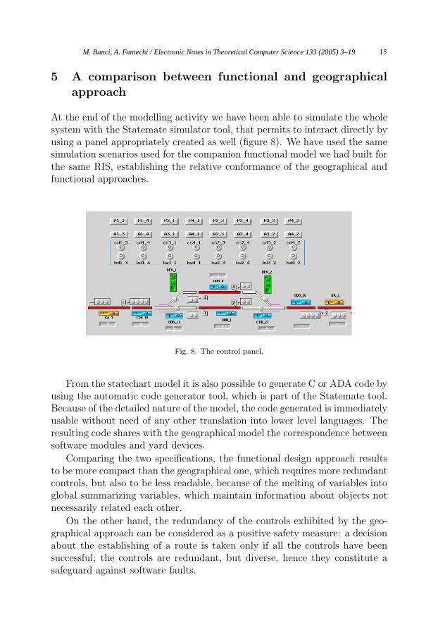
At the end of the modelling activity we have been able to simulate the wholesystem with the Statemate simulator tool, that permits to interact directly byusing a panel appropriately created as well (figure 8). We have used the samesimulation scenarios used for the companion functional model we had built forthe same RIS, establishing the relative conformance of the geographical andfunctional approaches.
Fig. 8. The control panel.
From the statechart model it is also possible to generate C or ADA code byusing the automatic code generator tool, which is part of the Statemate tool.Because of the detailed nature of the model, the code generated is immediatelyusable without need of any other translation into lower level languages. Theresulting code shares with the geographical model the correspondence betweensoftware modules and yard devices.
Comparing the two specifications, the functional design approach resultsto be more compact than the geographical one, which requires more redundantcontrols, but also to be less readable, because of the melting of variables intoglobal summarizing variables, which maintain information about objects notnecessarily related each other.
On the other hand, the redundancy of the controls exhibited by the geo-graphical approach can be considered as a positive safety measure: a decisionabout the establishing of a route is taken only if all the controls have beensuccessful; the controls are redundant, but diverse, hence they constitute asafeguard against software faults.
M. Banci, A. Fantechi / Electronic Notes in Theoretical Computer Science 133 (2005) 3–19 15
5.1 The revalidation activity
Our main interest for the geographical approach lies in the possibility to re-duce the revalidation effort needed when the yard is modified.
The main question is: “Do we have to revalidate the whole system? Orthere is the possibility to understand what is actually changed, so to limit therevalidation effort?”
Actually, in the geographical approach, in case of a change to some partsof the interlocking system there may be some modules that do not need tobe changed because they are not affected by the modification done, neitherdirectly nor by propagation. Since each object performs its controls indepen-dently and the system does not use global summarizing variables, we can assertthat those objects do not have to be revalidated. The objects affected by themodification need instead to be revalidated, e.g. using new test scenarios ormodifying the already existing ones.
5.2 The interaction table
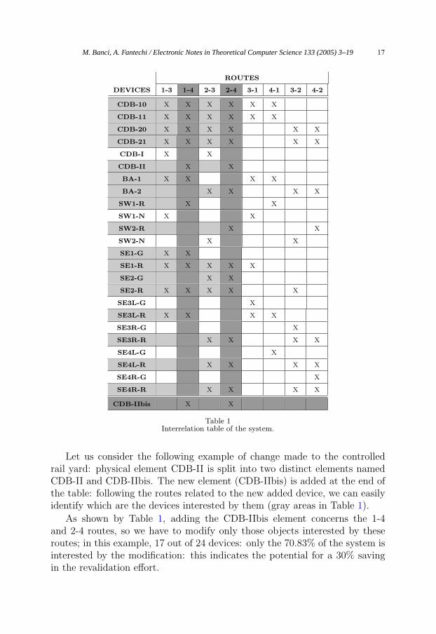
In order to select the objects that need or need not to be revalidated in faceof a change, we should follow the interrelations between the objects, whichpropagate the change effects from the components directly associated withthe physical devices affected by the change. These interactions between theobjects are easily illustrated in an interrelation table, which is exemplified forthe considered case study in Table 1.
Such a table shows the relation between routes (columns) and devices(rows). For each route there is a set of devices and equipments used to establishthe route command and, viceversa, a device could be used by one or moreroutes.The interrelation table is in general an useful tool that allows to relate anobject to another. It is however useful only because we have implemented themodel in the geographical way. If we define a similar interaction table for afunctionally designed model, we will find out that there will be the 100% ofcorrelation between objects, due to the dependence by a single central element(the condition table).
The interrelation table can be extracted from the geographical model: con-sidering for example the chart in figure 7 we can immediately notice the in-terrelation between the semaphore SE1-A-D-GREEN (SE1-G in Table 1) andthe routes 1-3 and 1-4, which in their turn are interrelated with a set of otherobjects such as CDB-10, CDB-11, etc.
M. Banci, A. Fantechi / Electronic Notes in Theoretical Computer Science 133 (2005) 3–1916
ROUTES
DEVICES 1-3 1-4 2-3 2-4 3-1 4-1 3-2 4-2
CDB-10 X X X X X X
CDB-11 X X X X X X
CDB-20 X X X X X X
CDB-21 X X X X X X
CDB-I X X
CDB-II X X
BA-1 X X X X
BA-2 X X X X
SW1-R X X
SW1-N X X
SW2-R X X
SW2-N X X
SE1-G X X
SE1-R X X X X X
SE2-G X X
SE2-R X X X X X
SE3L-G X
SE3L-R X X X X
SE3R-G X
SE3R-R X X X X
SE4L-G X
SE4L-R X X X X
SE4R-G X
SE4R-R X X X X
CDB-IIbis X X
Table 1Interrelation table of the system.
Let us consider the following example of change made to the controlledrail yard: physical element CDB-II is split into two distinct elements namedCDB-II and CDB-IIbis. The new element (CDB-IIbis) is added at the end ofthe table: following the routes related to the new added device, we can easilyidentify which are the devices interested by them (gray areas in Table 1).
As shown by Table 1, adding the CDB-IIbis element concerns the 1-4and 2-4 routes, so we have to modify only those objects interested by theseroutes; in this example, 17 out of 24 devices: only the 70.83% of the system isinterested by the modification: this indicates the potential for a 30% savingin the revalidation effort.
M. Banci, A. Fantechi / Electronic Notes in Theoretical Computer Science 133 (2005) 3–19 17
The advantages from this point of view are greater when the change affectsonly a marginal part of the layout, that is some device is actually used onlyby few routes.
About scalability of these considerations to larger designs, though we havenot made further experiments, we can observe that in practice is not con-venient to have in a railway yard a single device which is common to manyroutes, since this limits the capacity of the yard in term of the number ofsafe simultaneous set routes: independency among routes indeed sought as aprimary objective in the design of the yard itself.
6 Conclusions
The experience we have presented is part of a wider research project aiming atinvestigating the design of RIS by means of different Statechart dialects anddifferent commercial tools that support Statecharts, such as for example State-flow (MathWorks), Telelogic TAU Generation 2 (Telelogic), Real-Time Studio(Artisan Software), visualSTATE (IAR Systems). We have concentrated inthis paper on the possibility of adopting a geographical approach, with themain aim of investigating the reduction of revalidation effort in case of change.In this direction we need to verify the scalability to larger designs. Moreover,we need to assess the suitability of this approach to formal verification on oneside (by means of model checkers such as the one integrated in Statemate, orsuch as other academic tools), and, on the other side, to automatic generationof the statechart model from a specification of the physical layout.
References
[1] S. Bacherini, S. Bianchi, L. Capecchi, A. Felleca, A. Fantechi, E. Spinicci. Modelling a railwaysignalling system using SDL, Symposium on Formal Methods for Railway Operation andControl Systems (FORMS 2003), Budapest, Hungary, 15-16 May 2003.
[2] J. Berger, P. Middelraad, and A.J. Smith. EURIS, The European railway interlockingspecification. UIC, Commission 7A/16, 1992. In IRSE Proceedings 1992/93, pages 70–82, 1993.
[3] A. Cimatti, F. Giunchiglia, G. Mongardi, D. Romano, F. Torielli and P. Traverso, 1998,Formal Verification of a Railway Interlocking System using Model Checking, Formal Aspectsof Computing, Vol 10, 361-380.
[4] P. E. Debarbieri, F. Valdambrini, E. Antonelli. A.C.E.I. Telecomandati per linee a semplicebinario, schemi I-0/19. CIFI Collana di testi per la preparazione agli esami di abilitazione,Quaderno 12, 1987.
[5] European Committee for Electrotechnical Standardization, 2001, EN 50128, Railwayapplications Communications, signaling and processing systems Software for railway controland protection systems.
[6] W. J. Fokkink, P. R. Hollingshead, 1998, Verification of Interlockings: from Control Tables toLadder Logic Diagrams, Proceedings of the 3rd Workshop on Formal Methods for IndustrialCritical Systems - FMICS‘98.
M. Banci, A. Fantechi / Electronic Notes in Theoretical Computer Science 133 (2005) 3–1918
[7] U. Foschi, M. Giuliani, A. Morzenti, M. Pradella, P. San Pietro. The role of formal methods insoftware procurement for the railway transportation industry, Symposium on Formal Methodsfor Railway Operation and Control Systems (FORMS 2003), Budapest, Hungary, 15-16 May2003.
[8] B. Fringuelli, E. Lamma, P. Mello, G. Santocchia. Knowledge-Based Technology for ControllingRailway Stations. In IEEE Intelligent Systems, Volume: 7, Issue: 6, Dec. 1992, Pages: 45-52.
[9] D. Harel. Statecharts: A Visual Formalism for Complex Systems. Sci. Comput. Programming8 (1987), 231-274.
[10] D. Harel, H. Lachover, A. Naamad, A. Pnueli, M. Politi, R. Sherman, A. Shtull-Trauring,M. Trakhtenbrot, STATEMATE: A Working Environment for the Development of ComplexReactive Systems, IEEE Transactions on Software Engineering, Vol. 16, N. 4, April 1990, pp.403-414.
[11] D. Harel, A. Pnueli, J. Schmidt and R. Sherman. On the Formal Semantics of Statecharts,Proc. 2nd IEEE Symp. on Logic in Computer Science, Ithaca, NY, 1987, pp. 54-64.
[12] D. Harel and M. Politi, Modeling Reactive Systems with Statecharts: The STATEMATEApproach, McGraw-Hill, 1998. (Early version titled: The Languages of STATEMATE, I-Logix,Inc., Andover, MA, 1991.)
[13] J. Klose, W. Damm, 2001, Verification of a Radio-Based Signaling System Using theSTATEMATE Verification Environment , Formal Methods in System Design, 19(2).
[14] G. Kolk. Formal methods: Possibilities and difficulties in a railway environment from auser perspective. In Proceedings of the Third International Workshop on Formal Methodsfor Industrial Critical Systems, May 25-26, 1998, 1998.
[15] Niklaus H. Koenig, Stefan Einer The Euro-Interlocking Formalized Functional RequirementsApproach (EIFFRA), Symposium on Formal Methods for Railway Operation and ControlSystems (FORMS 2003), Budapest, Hungary, 15-16 May 2003.
[16] Object Management Group, 1999, Unified Modeling Language Specification, Version 1.5http://www.omg.org/technology/documents/formal/uml.htm
[17] Statemate Magnum Simulation Reference Manual. I-Logix Inc. Burlington, MA USA, 2003.
[18] Fokko van Dijk, Wan Fokkink, Gea Kolk, Paul van de Ven and Bas van Vlijmen, 1998 EURIS,a Specification Method for Distributed Interlockings, Lecture Notes in Computer Science, vol.1516.
M. Banci, A. Fantechi / Electronic Notes in Theoretical Computer Science 133 (2005) 3–19 19