Embed Size (px)
Citation preview

GEOLOGIC DISTURBANCES IN ILLINOIS COAL SEAMS
W. John Nelson
Illinois Department of Energy and Natural Resources STATE GEOLOGICAL SURVEY DIVISION
CIRCULAR 530 1983

Printed by the authority of the State of lllinois/7983/3000
Nelson, W. John Geologic disturbances in Illinois coal seams. - Champaign, Ill. :
lllinois State Geological Survey, 1983.
50 p. : ill. ; 28 cm. - (Illinois-Geological Survey. Circular ; 530)
1. Coal mines and mining. I. Title. I I. Series.
Graphic artist: Sandra Stecyk Editor: E. W. Stenzel

W. John Nelson
CIRCULAR 530 1983
ILLINOIS STATE GEOLOGICAL SURVEY Morris W. Leighton, Chief
Natural Resources Building 61 5 East Peabody Drive Champaign,. l llinois 61 820

CHANNELS Pleistocene Channels Pennsylvanian Channels
Channels of Anvil Rock Sandstone Walshville channel Galatia channel Distinguishing channels from geologic faults
SPLIT COAL Mining Conditions Splits in the Murphsyboro Coal Splits in the Seelyville Coal Splits in the Springfield (No. 5) Coal Splits in the Herrin (No. 6) Coal Case Studies in the Herrin (No. 6) Coal
ROLLS Rolls of Gray Shale and Siltstone Rolls of Sandstone Rolls of Gray Shale Under Black Shale Rolls of Limestone
LIMESTONE BOSSES
CLAY DIKES
WHITE TOP
IGNEOUS DIKES
JO l NTS
COAL BALLS
MISCELLANEOUS DISTURBANCES Glacial Origin The Hil l at Peabody Mine No. 10 Concretions Fossil Tree Stumps
G LOSSARY
FIGURES 1 Pleistocene valleys 2 Thickness of glacial drift 3 Coal seams and rock units 4 Cross section of channels affecting Herrin Coal 5 Channels and splits in Herrin Coal 6 Channels at Crown I Mine 7 Channels at Peabody No. 9 Mine 8 Features near mouths of large rivers 9 Distribution of rocks overlying Herrin Coal
10 Galatia channel and split Springfield Coal 11 Channel and split coal in Saline County 12 Distinguishing channels from faults 13 Locating channels by seismic profiling 14 Split coal may form in three ways 15 l nterlaminated coal, bone, and shale 16 Herrin Coal with "blue band" and cleat 17 Walshville channel and split coal in "Quality Circle" 18 Split coal at Old Ben Mine No. 11 19 Cross section of disturbed belt 20 Part of Old Ben Mine No. 21 21 Typical rolls in gray shale 22 Rolls in gray shale 23 Sandstone roof and rolls at Inland Mine No. 1 24 Sandstone-filled rolls 25 Rolls at Old Ben Mine No. 24 26 Lithology of Old Ben Mine No. 24 27 Cross section of limestone roll at River King Mine 28 Limestone rolls at River King Mine 29 Limestone roll at Camp Mine No. 11 30 Limestone bosses 31 Clay dikes in Springfield Coal 32 Clay dikes in Herrin Coal 33 White top 34 lgneous dikes 35 lgneous dikes 36 Joints in Anna Shale 37 Coal balls in Old Ben Mine No. 24 38 Coal ball 39 Multiple zones of coal balls 40 Peabody Mine No. 10 showing hill 41 Cross section of hil l 42 Theory of how the hil l formed 43 Large concretion 44 Fossil tree stump

ABSTRACT Mining problems result when coal seams are broken, dis- torted, or intruded upon by geologic features such as:
channels
sp /its
rolls
clay dikes
igneous dikes
coal balls
(Pleistocene or Pennsylvanian riverbeds) filled with rock or unconsolidated deposits that cut into coal seams, weaken roof strata, and store groundwater. Near some channels, coal may be thick, low in sulfur and high in ash content-and split.
(overbank or floodwater deposits in peat swamps) that are layers of noncoal materials divide coal seams horizontally; they either make it impossible to mine the seam as one unit, or increase the product's waste rock and ash content.
(small, infilled channels) or lenses of roof rock that protrude into the top of coal seams, producing steep dips or abruptly thin seams as well as poor roof conditions.
(vertical, clay-filled cracks in peat) that in- trude from overlying rock into coal seams, increase the product's waste rock and ash content, and cause unstable roof conditions.
(magma-f illed fractures in coal seams) intrude steep walls of rock into coal seams; they may be surrounded by coal coked from the heat of the magma.
(mineralized peat)-so hard and dense com- pared to the surrounding coal that massive deposits damage mining equipment and sometimes halt operations.
Other disturbances include limestone bosses, white top, joints in coal and roof rock, and deformation by glacial ice, concretions, and fossil tree stumps. Most can be recognized during exploratory drilling and by use of seismic explora- tion or surveying. Some features, such as channels and splits, are extensive enough to be mapped ahead of mining; others are localized and unpredictable.
INTRODUCTION Coal miners always face obstacles in their struggle to win coal from the earth. Coal beds-normally thick, level, and continuous-sometimes pitch sharply up or down, split into layers too thin to follow, f i l l with veins of clay or masses of stone, or end abruptly against solid rock. Unexpectedly, the roof may become almost impossible to support. Volumes of water or deadly gases may rush in a t the face. The risks and the costs, especially in lives, are great for miners, mine owners, and mining communities.
Locating, predicting, and controlling geologic hazards in coal seams depend upon knowing how they formed: What combination of climate, landscape, and vegetation produced coal seams and the disturbances associated with them, such as channels, splits, rolls, limestone bosses, clay and igneous dikes, and coal balls?"
According to geologists, most of these disturbances developed while the coal itself was forming-during the Pennsylvanian Period, approximately 31 5 to 280 million years ago. A t this time, coal beds and other sedimentary rocks began as layers of peat, mud, si l t , and sand deposited in rivers, lakes, swamps, deltas, tidal flats, and oceans. The original sediments were often laid down irregularly. Peat beds were frequently scoured and ripped up when rivers changed courses or overflowed banks; or they were torn apart when underlying sediments slumped in landslides. Later, the coal-to-be was squeezed and contorted as it was buried beneath thousands of feet of sediment; and occa- sionally, coal seams were pierced and baked by molten magma. More recently, during the Pleistocene Epoch, enor- mous masses of glacial ice deformed coal beds near the surface, while rivers of glacial meltwater washed away other coal seams.
To describe the problems, then to identify the causes of these disturbances in Illinois coal seams required exten- sive mapping of both surface and underground mines. Field investigation for this project covered every active mine in Illinois. Other sources of information included the Geolog- ical Survey's large collection of notes, photos, sketches, and maps of active and abandoned mines as well as drillers' logs, geophysical logs, and core descriptions.
"Another publication discusses faults: Illinois State Geo- logical Survey Circular 523, Faults and Their Effect on Coal Mining in lllinois, W. J . Nelson, 1981.
GEOLOGIC DISTURBANCES I N l LLlNOlS COAL SEAMS
Since both miners and geologists are especially con- cerned with the effects of geologic disturbances on lllinois coal mining, both points of view are presented in the following report.
CHANNELS A channel i s the course of an ancient river that eroded part or all of a coal seam and/or the adjacent layers of rock. Because channels are widespread in the lllinois Basin Coal Field, many have serious effects on coal mining. (Contem- porary river channels, which are easy to identify and avoid, cause no serious problems.) Miners call ancient river chan- nels by various names: washouts and cutouts are commonly used when the seam has been completely eroded.
In Illinois, coal mining i s affected by channels formed during two geologic periods: (1) the Pleistocene Epoch, beginning about 2 million years ago, when this region was invaded repeatedly by glaciers; and (2) the Pennsylvanian Period, 315 to 280 million years ago, when layers of coal- forming peat accumulated in vast tropical swamps. Some Pennsylvanian channels already existed as the peat was accumulating, while others developed later as sediment- covered peat beds became eroded.
Pleistocene Channels For this report, Pleistocene channels are defined as valleys or watercourses filled with materials deposited during the Pleistocene Epoch. Although geologists dispute the ages of various channels, some of these channels were probably cut before the first advance of glacial ice over Illinois (Willman and Frye, 1970).
Four major stages of Pleistocene glaciation (ice ages) left their record in Illinois. At one time or another, glaciers covered nearly all the land now underlain by coal. They blocked and altered the courses of rivers, including the precursors of the Mississippi, Ohio, and Illinois Rivers. During the warm interglacial stages, they left thick deposits of clay, sand, gravel, and boulders to f i l l valleys and pro- foundly change the topography. Great torrents of meltwater scoured valleys and cut through older deposits into bedrock. ,
When the ice returned, these valleys were buried again. Consequently, many Pleistocene channels are com-
pletely buried, have little or no relationship to present drainage patterns (fig. I), and can be detected only by drilling or by other subsurface exploration. Gne of the largest and most important buried channels is the Mahomet Bedrock Valley. Created by the ancient Teays River, this channel originated in West Virginia, crossed Ohio and Indiana, and entered lllinois just north of Danville. The virtually level farmland north of Champaign and Danville gives no clue to the presence of this buried valley, which is several miles wide and more than 400 feet deep (Piskin and Bergstrom, 1975).
A variety of unconsolidated deposits, known collectively as glacial drift, f i l l Pleistocene channels. Many channels
contain a type of drift called outwash, a well-sorted sand and gravel left by meltwater rivers. Outwash is highly permeable and may yield large quantities of groundwater. In fact, the thick sand and gravel deposits in the Mahomet Bedrock Valley are an important source of groundwater for central Illinois. Not all subsurface deposits commonly found in Pleistocene channels transmit or store water so readily. Fine-grained deposits from glacial lakes and sluggish streams are less permeable. The poorly sorted mixtures of clay, sand, gravel, and boulders, which are called till, also supply little groundwater. Figure 2 shows the generalized thickness of glacial drift in Illinois. Additional details on the thickness and nature of glacial drift are presented by Willman and Frye (1 970) and Piskin and Bergstrom (1 975).
Underground miningproblems. A Pleistocene channel i s a hazard to underground mining. Not only do such channels hold large amounts of groundwater, but they also contain loose materials that are nearly impossible to support in the roof. Many fatalities in the early history of mining, including the drowning of 69 men in the Diamond Mine disaster of 1883, resulted from mining too closely under water-saturated deposits of sand and gravel. If such a chan- nel i s penetrated in mining, or undermined and exposed in a roof fall, the sand and gravel as well as the water could rush into the mine. Fortunately, such dangers can be avoided by subsurface exploration before mining. Careful logging of test holes i s critical in areas of shallow underground mines so that the extent of Pleistocene channels can be assessed accurately.
Penetrating channels is not the only danger involved in shallow underground mining in areas of buried Pleistocene valleys. Roof failure, rib rashing, and squeezes occur more often under buried valleys than elsewhere. The shallower the mine and the greater the relief on the bedrock surface, the more severe the problems. In mountainous regions, such as West Virginia, the roofs of mines are frequently unstable under stream valleys. Here in Illinois, three docu- mented cases of floor failure leading to squeezes and subsi- dence were related to mining under Pleistocene channels. In all three situations, the valleys were deeper than 100 feet, and the glacial drift was thicker than the bedrock above the coal (Hunt, Bauer, and DuMontelle, 1982).
Engineering studies based on computer modeling indicate that compressive stresses on pillars and roof corners (junctions of roof and rib) and tensile stresses on midspans of entries are higher under valleys than under hills (Wang, Ropchan, and Sun, 1974). Compression on pillars can produce rib rashing and squeezes, while tension on the midspan promotes roof failure. Ferguson (1967) states that rock under valleys is weakened by microfrac- turing invisible to the naked eye; such microfracturing is produced when the valleys are eroded and overburden pressures are relieved, allowing the rock to rebound into the valley. Mechanical testing of core samples a t the lllinois State Geological Survey reveals that shales beneath buried
l LL lNOlS STATE GEOLOGICAL SURVEY CIRCULAR 530

KEMPTON V
0 10 20 3 0 4 0 M i l e s - 0 20 40 6 0 Kilometers -
Figure 1 Pleistocene valleys or channels in Illinois, compared with present drainage systems ( f rom Piskin and Bergstrom, 1975).
GEOLOGIC DISTURBANCES IN l LLlNOlS COAL SEAMS

Figure 2 Generalized thickness of glacial dr i f t in Illinois (from Piskin and Bergstrom, 1975).
4 l LLlNOlS STATE GEOLOGICAL SURVEY CIRCULAR 530

valleys are up to 25 percent weaker than the same shales away from valleys (R. A. Bauer, personal communica- tion, 1982).
Surface miningproblems. A few years ago, a surface mine was abandoned in Jackson County because of channels. The coal seam was not eroded, but the channels contained water-saturated sand that flowed like quicksand into the pits. In turn, movement of the sand triggered large-scale slumping of overlying till into the excavations. Water, sand, and ti l l filled the pits faster than they could be removed. Channels a t this site were as much as 50 feet deep, but only a few hundred feet wide. To accurately map channels with such dimensions, closely spaced drilling i s necessary.
Pleistocene channels filled with sand and gravel may serve as sources of groundwater for homes, farms, and villages. Mining through such aquifers may deplete or pollute supplies. The risks must be considered in the planning of surface mines.
Pennsylvanian Channels Many large river systems existed during the Pennsylvanian Period; some prevented peat from accumulating and some eroded existing peat beds. Three well known channel systems have profound effects on coal mining in Illinois:
Anvil Rock Sandstone and younger sandstone fi l l channels that interrupt the Herrin (No. 6) Coal Member. These channels cut through the Herrin peat after it was covered with sediments. The Walshville channel was the course of a major river existing during and following accumu- lation of the Herrin peat. The Galatia channel was the course of a major stream coexisting with the peat that became the Springfield (No. 5) Coal Member.
Channels affecting coal seams other than the Herrin and Springfield are known in less detail and will be discussed last.
Channels of Anvil Rock Sandstone and younger sandstones The Anvil Rock Sandstone Member i s a rock unit that occurs above the Herrin (No. 6) Coal Member (figs. 3 and 4). In some parts of Illinois, however, the Anvil Rock Sand- stone fills channels eroded into or completely through the Herrin Coal (fig. 5).
The largest channel meanders across southern Illi- nois from Gallatin to Randolph County (fig. 5). The Herrin Coal was eroded by this stream along a belt that ranged from slightly less than 1 mile to more than 4 miles wide. In some places, coal seams as deep as the Colches- ter (No. 2) Coal, 200 feet below the Herrin Coal, have also been cut out. Sandstone and siltstone mainly fill the channel, with some conglomerate near the base. The channel-fill deposits average 122 feet thick, and
Danville (No. 7) Coal
Anvil Rock Sandstone Anna
Turner Mine Shale Dvkersbura
Roodhouse Kerton Creek Coal Coal
Colchester (No. 2) Coal
Gimlet Sandstone
Walshville channel
Galatia channel
Francis Creek Shale
Cardiff Coal
Oraville channel
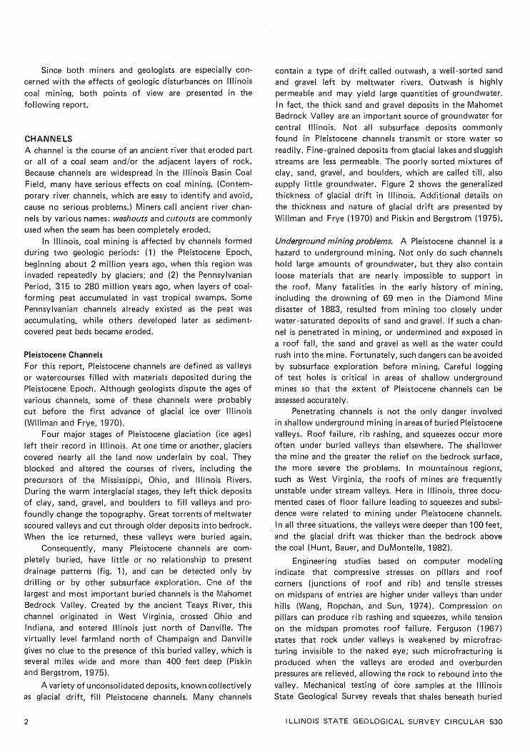
Figure 3 Coal seams and rock units discussed in this report; other units omitted. (Not to scale.)
GEOLOGIC DISTURBANCES I N ILLINOIS COAL SEAMS

CONTEMPORANEOUS CHANNEL
POST-COAL CHANNEL
Figure 4 Cross section showing channels that affect the Herrin (No. 6) Coal Member.
in some places, exceed 200 feet (Hopkins, 1958). Electric logs of oil-test holes have provided most of the data for this channel. Only one underground mine, the Clarkson Coal and Mining Company at Nashville (abandoned in 1940), mined up to i t s edge. No geologic details were available from this mine; nor was information obtained from a reported exposure of the channel at a surface mine in Randolph County. Only the closely spaced drill holes along the channel show the steep walls or banks where coal has been abruptly cut out and replaced by sandstone or siltstone.
Smaller channels filled with Anvil Rock Sandstone have been identified in several areas of Illinois. Active and abandoned underground mines in Christian, Macoupin, Montgomery, and Sangamon Counties provide the best documented examples (fig. 5). Most are a few hundred feet wide and at least several miles long. They show no preferred direction; some are nearly straight, but others branch and curve. In some channels, sandstone has com- pletely replaced the Herrin (No. 6) Coal. In others, the sandstone or other channel-fill rocks form the immediate roof of a partly eroded coal seam. Still other channels eroded no coal a t all, but scoured away the normal roof of black shale and limestone. Channels that incompletely eroded the coal or that only eroded and replaced roof strata are well documented (Simon, 1956; Potter and Mast, 1963; DeMaris et al., 1979; Nelson and Nance, 1980).
A recent, detailed study shows that some channels, previously mapped as Anvil Rock, are actually filled with deposits younger than this sandstone. In central Illinois, for example, the Herrin (No. 6) Coal is completely eroded in two long, narrow, north-south trending channels. The first i s in eastern Montgomery County where drill holes show a channel f i l l of sandstone younger than the Anvil Rock-probably the Gimlet Sandstone Member of the
Modesto Formation (fig. 5); this channel i s 200 to 300 feet wide and at least 6 miles long. To the west, a longer and wider cutout extends through Montgomery, Bond, Clinton, and Washington Counties; it i s 1000 to 2000 feet wide and nearly straight to slightly curving. Either Anvil Rock or Gimlet Sandstone fills it. Both of these channels were encountered in now-abandoned underground mines; no geologic details on the channels are available.
No attempt was made to distinguish channel systems of different ages in figure 5. In some cases the evidence is incomplete. As to any effect on mining, the distinction is insignificant.
Mining problems. Recently surface mines in Jackson, Wil- liamson, and Gallatin Counties have exposed narrow channels of Anvil Rock Sandstone, locally replacing the Herrin (No. 6) Coal. Not enough information is available to map these cutouts away from the mines. In some cases, channel sandstone i s porous and weakly cemented, so it conducts large amounts of water into the pits and slumps on the highwall. In other cases, the sandstone i s hard and massive. To blast and remove it from the pit is difficult, especially for for the small operator without a large dragline or stripping shovel. Furthermore, large blocks of sandstone may roll off the highwall without warning, crushing men and equipment below.
Underground mines present other problems (fig. 5); A southwest-trending channel about 500 feet wide completely cut out the coal at the abandoned Crown I Mine of Freeman Coal Mining Company in Montgomery County. It divided the mining property into two unequal parcels. To reach the coal northwest of the channel, Freeman had to drive sets of entries through solid rock. Mining in and near the chan- nel was hazardous because of unstable, slickensided roof rock. Slickensides, which are common around the margins
6 ILLINOIS STATE GEOLOGICAL SURVEY CIRCULAR 530

SANGAMON A 1 PI ATT
r-' MOULTR'E
=AY ETTE EFFINGHAM
CLAY
I MARION
CO LES I EDGAR
CUMBERLAND -----i
JASPER
GEOLOGIC DISTURBANCES IN ILLINOIS COAL SEAMS
Anvil Rock and other younger channels
3.y;;;z.: Walshville channel . . . .. . . ... . . . . . (contemporaneous with coal)
r A split coal
Figure 5 channels and split coal in Herrin (No. 6) Coal Member (revised from Smith and Stall, 19751,

Figure 6 channels cutting out coal at the abandoned Freeman Crown I Mine. The channel f i l l is primarily gray silty shale and siltstone; slickensides were caused by uneven compaction.
of many channels, apparently were formed by slippage as sand, peat, and mud compacted unevenly while turning into rock. At Crown 1 Mine, the coal was cut out sharply, but unevenly and at a low angle. The channel fill was mainly fine-grained sandstone, siltstone, and shale with some lenses of conglomerate (fig. 6).
At another abandoned mine, the Peabody Mine No. 9 in Christian County, a complex branching system of Anvil Rock channels carved the Herrin Coal (Payne and Cady, 1940). Where the coal cut off at angles as great as 45 degrees, siltstone and silty shale replaced it (fig. 7). One set of entries driven across the channels encountered an island of coal completely surrounded by channel - f ill rocks. Such a feature confirms that Anvil Rock channels occasionally changed their courses, as do many modern streams.
The most serious mining problem associated with these channels i s wet working conditions. The Anvil Rock Sandstone frequently contains copious amounts of water, which flow or seep into the mine as the face advances. Since the seepage is likely to be dispersed over a wide area, gathering and pumping the water can be difficult. De- watering or grouting the sandstone in advance may not be practical because this sandstone has low permeability. Also it may be divided into a series of separate, lens-shaped reservoirs (Nelson and Nance, 1980).
Roof stability under channel deposits varies greatly. Some sandstones are tightly cemented and make as solid a roof as limestone. Other sandstones and some sandy or silty shales are brittle, thinly laminated, and very difficult to support. Where sandstone overlies shale in the roof, the shale separates easily from the irregular, often slickensided base of the sandstone.
The Walshville channel An ancient river, as large as the present Mississippi River, flowed through the swamp where peat that became the Herrin (No. 6) Coal was accumulating. Its course became the Walshville channel (fig. 5), about 230 miles long and from 1 to more than 5 miles wide. This channel has been mapped continuously from i t s northern outcrop in Douglas County southwestward to i t s southern outcrop in Jackson County (Treworgy and Jacobson, in press). Probably, i t s source was in northern Michigan or in Canada, and i t s mouth was southwest of Illinois. Since no Pennsylvanian rocks exist today in these areas, we cannot be certain.
The Walshville channel contains no Herrin (No. 6) Coal-only shale, siltstone, sandstone, and conglomerate. The coal i s missing, not because it was eroded, but because coal-forming peat did not accumulate in the riverbed. But as the Walshville changed i t s course many times, like the Mississippi and other modern streams, the former riverbeds or old channels filled with peat and other sediments. Some changes were gradual: the current undermined banks, carried away sediments, and deposited them downstream. Other changes were sudden: the river flooded, tore through i t s natural levees, and made new channels across the nearly flat alluvial plain. This happened most commonly where a river meander had developed into a broad loop. During a flood, the water cut across the narrow neck of the meander, shortening and straightening i t s course. The abandoned por- tion became an oxbow lake that gradually filled with sedi- ments (fig. 8). For example, in western Franklin County the Walshville channel makes a complete loop, surrounding an "island" where the Herrin Coal i s present. The eastern portion of this loop probably was the older course of the
I LLlNOlS STATE GEOLOGICAL SURVEY CIRCULAR 530

Figure 7 Channel cutting out the Herrin (No. 6) body Mine No. 9 in Christian County: where the coal has been eroded at a 45'
Coal at the abandoned Pea- view of the channel's edge, angle.
channel. The same process occurred during the flood of 1844 at Kaskaskia, Illinois. The Mississippi River cut a new, shorter course to the east, wiped out most of the settlement, and left Kaskaskia an island. The old course of the Mississippi River west of Kaskaskia has gradually filled with sediment so that now a part of Illinois lies west of the river.
The Walshville channel influenced deposition of the Herrin peat and associated sediments. Coal i s thickest along the channel (especially in the "Quality Circle" of southern Illinois) because swamps bordering the river received a steady supply of nutrients, and vegetation flourished. Areas away from the channel frequently dried out, which inhibited plant growth as well as peat develop- ment. Plant material must be submerged constantly, other- wise it will decompose and not be preserved as peat.
Periodic flooding of the Walshville River produced some distinctive deposits. In many places near the channel, the Herrin Coal contains splits within the seam. Splits are layers of shale (occasionally siltstone or sandstone) from 1 inch to many feet thick; most represent sediments washed into the swamps during floods. The rocks directly overlying the Herrin Coal along the channel also formed from sedi- ments deposited by floodwaters (fig. 9). In most areas away from the channel, the black, fissile Anna Shale Member and the Brereton Limestone (both marine-water deposits) over- l ie the coal. Near the channel, however, a medium gray shale or siltstone called the Energy Shale Member lies between the coal and the Anna Shale (Algaier and Hopkins, 1975) (figs. 3 and 4). The Energy Shale thickens close to the channel, locally reaching more than 100 feet. The presence of this thick freshwater deposit indicates that the river
continued to flow after accumulation of peat had ended. An important feature of the Energy Shale i s i t s rela-
tionship to low-sulfur Herrin Coal deposits (<2.5% S), found only where the overlying Energy Shale is about 20 feet thick or more. Coal topped by black shale, lime- stone, or thin Energy Shale i s invariably high in sulfur (3% to 5% S). Evidently, much of the sulfur in coal came from seawater, as does the sulfur in contemporary peat deposits that are periodically flooded by the sea (e.g., the Florida Everglades). A thick deposit of Energy Shale above the peat protected the peat from infiltration by sulfur- bearing ocean water, so this coal remained low in sulfur (Gluskoter and Hopkins, 1970).
The Walshville channel simultaneously created favorable and unfavorable conditions for coal mining. The thick, low- to medium-sulfur coal along the channel has long been a prime target for mining. But the channel also pre- vented the deposition of peat, eroded large areas of coal, and produced severe irregularities in the seam (see section on SPLIT COAL: Case Studies, p. 21 ).
The Galatia channel The Galatia channel in southeastern Illinois i s the course of a stream that was flowing when the Springfield (No. 5) Coal was forming (Hopkins, Nance, and Treworgy, 1979). Roughly 1/2 to 3/4 mile wide, this channel has been traced about 150 miles southwestward from l ndiana (Auk, Sulli- van, and Tanner, 1980) through Wabash County, Illinois, to i t s outcrop in Saline County, Illinois (Hopkins, 1958) (fig. 10). The Galatia channel i s filled mainly with siltstone and sandstone, averaging about 40 feet thick.
Just as the Herrin (No. 6) Coal thickens close to the Walshville channel, the Springfield (No. 5) Coal thickens toward the Galatia channel. It commonly exceeds 6 feet thick, reaching 10 feet thick in some places, although it i s rarely thicker than 5 feet elsewhere. Belts of thick coal range from less than 1 mile to more than 6 miles wide along both sides of the channel (Hopkins, 1958).
The Springfield Coal is commonly split along the margins of the Galatia channel (figs. 10 and 11). It also may be overlain by the Dykersburg Shale, a gray silty shale or siltstone that bears the same relationship to the Galatia channel as the Energy Shale to the Walshville channel (fig. 3). Low- to medium-sulfur coal is found where the Dykersburg Shale i s more than about 20 feet thick. Away from the channel, where thin Dykersburg Shale or black, fissile, marine shale overlies the Spring- field Coal, the coal always contains about 2.5 percent sulfur or more.
Other channels The Oraville channel apparently formed at the same time as the Murphysboro Coal Member in Jackson County, Illinois
GEOLOGIC DISTURBANCES I N l LLlNOlS COAL SEAMS 9

sand bars L approximately 5 miles I
ISGS 198:
Figure 8 Typical features found near the mouths of large rivers on coastal plains.
I LLlNOlS STATE GEOLOGICAL SURVEY CIRCULAR 530

Gray shale (Energy Shale) over 20 ft, \-L--_-.L_---_-_-:-~~---+ . . . . . . . . . . . . . . / JOHNSON j POPE , HARDIN \,
probably crevasse splays I I ! \
1 / / J
Figure 9 ~ is t r i bu t i on of roof rocks overlying the Herrin (No. 6) Coal (from Damberger, Nelson, and Krausse, 1980). Large area of thick gray shale in east-central Illinois probably represents a delta deposited in a large lake (Treworg~ and Jacobson, 1979).
GEOLOGIC DISTURBANCES IN l LLlNOlS COAL SEAMS 11

WAYNE EDWARDS WABASH *
SALINE 1
............ Dykersburg Shale
............ ............ ........... .thicker than 20 f t
Galatia channel
Split coal
Figure 10 Galatia channel, split Springfield (No. 5) Coal, and thick Dykers- burg Shale (revised from Smith and Stall, 1975; Hopkins, 1958; and Hopkins and Allgaier, 1975).
(Treworgy and Jacobson, in press). Along the borders of the sandstone-filled channel, the coal i s commonly split. Near the channel, gray shale and siltstone similar to the Energy and Dykersburg Shales overlie low-sulfur coal deposits. Underground mining concentrated in this thick low-sulfur coal, despite widespread shale splits in the seam, which sometimes made mining uneconomical.
Large resources of the Seelyville (Indiana I I I ) Coal have recently been mapped in east-central and southeastern Illinois. Splits are widespread. Locally, sandstone has replaced some coal. Channels probably developed contem- poraneously with the Seelyville deposits but more drilling is needed to be certain (Treworgy, 1980; 1981 ).
Both the Colchester (No. 2) and Danville (No. 7) Coal Members are relatively low in sulfur where they are overlain by thick nonmarine gray shale or siltstone. Although these relationships suggest channels contemporaneous with peat formation, neither channels nor split coal have been reported in these seams. Possibly the channels ran beyond the present boundaries of the Illinois Basin Coal Field and were removed by post -Pennsylvanian erosion (Treworgy and Jacobson, in press).
Distinguishing channels from geologic faults In mining operations, mistaking a channel for a geologic fault can be costly. Of course, channels contain no coal. Normally, coal i s located at about the same elevation on opposite sides of a channel. The most economical way to mine across a channel i s to drive a se t of level entries at right angles to the course of the cutout. In a fault, however, the coal has been displaced either up or down, so the entries must be graded to rejoin the seam. In fact, before the entries can be planned, the amount and direction of throw on the fault must be determined (Nelson, 1981).
Features a t the face can help miners decide whether a fault or a channel has been struck (fig. 12).
Previous experience in a particular mine and in the region will give clues about the nature of the obstruction in the coal. In some mines faults are encountered, but never channels; while in other mines the reverse i s true. Most coal companies drill test holes before trying to mine across either a large fault or channel. Drilling can be done either from the surface or within the mine. Standard procedure includes collecting and examining cores, which should remove all doubt about the obstacle and indicate the proper course of action.
Locating channels through exploratory drilling can be a challenge. Narrow channels such as those in central Illinois may be missed. Even if a core shows channel-fill sediments in place of coal, the investigator will not know the width, extent, and direction of the cutout. Additional holes must be drilled around the one indicating a channel.
People logging exploratory cores must be alert to any indications of erosion close to the top of the coal which may signify the presence of a channel. Any sandstone or conglomerate should be suspect, especially if it shows a sharp or inclined contact with rocks or coal below. The presence of coal pebbles or stringers in conglomerate is an almost certain indication of erosion. Not all channels, however, contain coarse-grained sediments; some are filled with shale or siltstone. Careful correlation of the logs or nearby holes may show that key, persistent rock layers are missing unexpectedly and are replaced by shale or siltstone. Another useful technique is constructing maps of the thick- ness of sandstones. Abrupt thickening of a sandstone may indicate the presence of a channel.
l LLlNOlS STATE GEOLOGICAL SURVEY CIRCULAR 530

GE
OL
OG
IC D
IST
UR
BA
NC
ES
IN
ILL
INO
IS C
OA
L S
EA
MS

Coal completely missing
Little or no change in elevation of coal on opposite sides of channel
Angle of cutout may exceed 45" but more commonly i s less than 45"
Coal commonly replaced by sandstone; less commonly by siltstone, shale, or conglomerate
Pebbles or stringers of coal common in channel filling
Surface of cutout may be very irregular
Slickensides may be present but are small and not consistently oriented
No gouge or breccia (gouge i s finely pulverized rock; breccia is rock broken into angular fragments and cemented together)
Rocks in channel may show slumped layering
Usually no clay or minerals at edge of channel
Figure 12 Criteria for distinguishing channels from faults.
High-resolution seismic profiling is a promising tool for locating channels and other disturbances. Seismic explor- ation can provide more information than drilling alone and cut costs by reducing the number of holes that must be drilled (fig. 13; Daly, 1979). Peabody Coal Company seismically located Anvil Rock channels and a 15-foot fault near i t s No. 10 Mine (Acker and Kumamoto, 1981). The presence of a fault and channels were confirmed with closely spaced drilling. Consolidation Coal Company also used seismic surveys to locate a channel near i t s Hillsboro Mine in Montgomery County, and later verified the channel by drilling (Coon et al., 1979).
Despite problems with identification, channels follow reasonably predictable patterns. In this respect they are easier to deal with than many other features discussed in this report. Many coal-seam disturbances (such as rolls and clastic dikes) are either localized, or vary greatly from s i te to site. They cannot be predicted ahead of the working face using existing techniques.
Splits are layers of shale, siltstone, sandstone, or other rock within a coal seam. Most seams contain thin partings (usually < I in. thick) of clay or shale, but these are not regarded as splits. No precise definition of split coal exists.
FAU LTS
No coal missing; seam i s merely displaced
Elevation of coal changes on opposite sides of fault
Angle of fault commonly 45" to vertical
Any type of rock may be found opposite to the faulted coal
No pebbles or stringers of coal (may be broken or crushed fragments)
Surface of fault generally planar or smoothly curved
Slickensides are common and consistently oriented on most fault surfaces
Gouge or breccia characteristic
Rocks opposite fault generally show normal layering
Commonly conspicuous fillings of clay or of mineral crystals in fractures and openings in rock
A practical definition includes any coal containing bands of rock that adversely affect the quality and/or rninability of the seam.
Most of the major coal beds in Illinois are split. Some splits are distributed statewide; others are local.
rigin Splits represent interruptions in the coal-forming process. At these times, inorganic materials were deposited in swamps. Certain coal beds in Germany and elsewhere contain layers of volcanic ash (tonsteins); but in Illinois coal seams, ail splits began as sediments deposited by water. Figure 14 illustrates how they developed.
Some splits are infilled channels of small streams that flowed through peat-forming swamps (fig. 14a); they can be recognized by their lenticular cross sections and linear or meandering outlines in map view. Along the margins of these splits, coal usually interfingers with the channel- f i l l deposits.
Other splits consist of sediments deposited in small lakes or ponds within the swamps (fig. 14b). Today, areas such as the present Mississippi delta contain hundreds of small, short-lived lakes that f i l l with mud and s i l t from floodwaters. If peat growth is re-established on these deposits, a split seam will eventually result. Also, splits that form in lakes or ponds are lenticular in cross section,
ILLINOIS STATE GEOLOGICAL SURVEY CIRCULAR 530

but have rounded or irregular outlines rather than the sinuous, linear patterns of stream deposits. Lake-bed deposits commonly consist of dark, very fine-grained shale with thin parallel laminations. Occasionally, cannel coal is associated with lake-bed deposits. Composed mainly of windblown spores and pollen from trees surrounding the water, cannel coal is dull, hard, and nonbanded with a waxy or greasy lustre. Usually, it i s higher in ash than banded coal.
Most splits in Illinois probably began as overbank deposits-sediments washed out of rivers and streams into the swamps during floods (fig. 14c). After the floodwaters receded, peat developed again on the sediments. In some places, this process was repeated many times, yielding coal beds with multiple splits. Overbank-derived splits may cover many square miles. Although such deposits are usually thin (a few inches to a few feet at most), some gradually thicken toward their channels. Fine-grained rocks such as mudstone, shale, or siltstone make up most of these splits.
Closely related to the overbank deposit i s the crevasse splay. When a river cut a large gap or crevasse through i t s natural levees (figs. 8 and 14), the diverted flow spread across the lowlands. Immediately a fan- or lobe-shaped deposit began to build up: a crevasse splay is, in fact, a small delta. (Today, crevasse splays are forming in deltas around the world, including the Mississippi delta). Sedi- ments were thickest and coarsest next to the crevasse, and gradually became thin and fine grained toward the outer edges. A split formed when a splay deposit, which had been building on top of a peat deposit, was abandoned. Then new peat grew on top of the splay. The Energy Shale and the Dykersburg Shale appear, in part, to be crevasse splays deposited by the Walshville and Galatia streams near the end of peat-forming periods.
Still another way of forming splits (not illustrated) was through a short-term rise in sea level. Swamps flooded with salt water, killed plants, and halted accumulation of peat. Thin marine sediments, such as black shale or limestone, settled on top of the peat. When the sea withdrew, a new peat swamp developed on top of the marine deposits.
eologists regard the two beds thus formed as separate coals. If the split is thin enough, however, the two seams can be mined together. In Illinois, minable coal split by marine rocks has not been documented.
Splits in a coal seam always hamper production, so mine operators generally have avoided them. l llinois contains large reserves of coal without splits, but as these deposits are mined out, attention will focus on mining split coal. Much of it i s thick and low in sulfur.
Thin splits can be mined with the coal. If the coal i s not cleaned, the ash content of the product is raised. In fact, the increase in ash i s greater than one might expect
0 0 0 0
I 1 mile I
Figure 113 Locating channels with high-resolution seismic profiling (modified from Daly, 1979). The upper grid represents 40 exploratory drill holes. Although one hole penetrated a channel, the available data gave no clues to the extent or trend of the channel. I n the lower diagram, 4 drill holes and 8 seismic profiles provide an accurate pattern of the cutouts.
because most split material i s about twice as dense as coal. If shale in a seam amounts to 1 percent by volume, it
contributes 2 percent ash by weight. Each inch of shale mined with a 6-foot seam adds roughly 2.5 percent to the ash content of the raw coal.
A preparation plant can remove some split material. Plants are designed to operate most efficiently within a certain range of percentage of waste in the raw coal. If this range is exceeded due to mining of severely split coal, the cleaning plant may not be able to handle the excess rock. The result will be either a dramatic increase in ash in the shipped coal, or large amounts of coal sent to the waste pile (increasing the hazard of fire). Furthermore, increased wear on crushers, screens, and other equipment will occur when large amounts of rock are sent to the preparation plant.
Another way to handle splits is to mine the coal in benches, separating the rock during mining. Disposing of waste rock is no problem in surface mining; it can be placed
GEOLOGIC DISTURBANCES IN ILLINOIS COAL SEAMS

(a) Spli t developed f rom stream in peat swamp (b) Split developed f rom pond or lake in peat swamp
(c) Spl i t developed f rom overbank or crevasse-splay deposit
Figure 14 Spl i t coal may form i n three ways.
in the spoils with the overburden. Removing the split, space for such storage i s limited, and spontaneous combus- however, raises the cost of mining. Special equipment may be necessary, as most loading machines are not well suited to removing thin layers of rock cleanly from the seam.
The difficulties of working separate benches are magnified in underground mining. Achieving clean separa- tion of coal from split material i s difficult or impossible with modern face equipment, especially with continuous miners. As in strip mining, the extra operation of removing
tion of gob is a serious problem. I f the rock i s sent out of the mine, it goes through the preparation plant; then the company must find a place on the surface for the waste.
I t i s also possible to mine only one bench of the split coal, leaving the split and other bench(es) in the ground. The resultant loss of reserves makes this practice unattrac- tive, unless the split lies close to the bottom or top of the seam. Thick splits near the middle of the seam present an
the split increases mining costs. If the splits are thick, the unhappy choice, especially in underground mining where
height of entries may become excessive, with increased maintaining a minimum working height is critical. Unless danger of roof and rib failure. Finally, disposal of waste the extent of the split i s known to be limited with good rock i s a problem. It can be stored in the mine asgob, but coal beyond it, mining may be halted.
16 l LL lNOlS STATE GEOLOGICAL SURVEY CIRCULAR 530

When a choice exists between mining an upper or a lower bench of split coal in a deep mine, the character and stability of the roof and floor are considered. If the lower bench is extracted, the split becomes the roof. Many splits are composed of weak shale or claystone, prone to slaking and generally weak. They may be weakened further by coaly stringers and partings as well as rooted zones (underclays) beneath the upper bench of coal. The roof also may split along bedding planes in the upper, unmined bench of coal. Another problem is that the lower bench frequently dips; mining it leaves depressions that accumulate water. In such a case, mining the upper bench would be preferable. In other cases, where the split consists of competent rock, and groundwater i s no problem, mining the lower bench of a split seam should cause little trouble.
Some splits, persisting over hundreds of thousands of acres and varying little in thickness, can be mapped accu- rately from exploratory drill holes. Most overbank deposits and crevasse splays fall into this category. Other splits, especially those from stream deposits, are localized. Since they vary from site to site, where they will appear ahead of the working face is almost impossible to predict. Mining plans can accomodate only uniform and continuous splits.
l i ts in the Murphysbsro The Murphysboro Coal of southern lllinois (formerly, but incorrectly, called the "No. 2 Coal") is mostly split where it i s thick enough to mine. Typicaily the coal divides into an upper bench 1 '/2 to 3% feet thick and a lower bench 3% to 4% feet thick. One shale bed persisted through nearly all, the underground mines formerly worked around Murphys- boro. The shale was medium to dark gray, fine grained, and often abundantly carbonaceous, containing stringers of coal; i t s thickness varied from less than I inch to as much as 36 feet (Andros, 1914; Jacobson, 1983). Toward the Oraville channel, the splitthickened gradually, repre- senting overban k or crevasse -splay deposits associated with the channel (Treworgy and Jacobson, 1979).
In addition to the main split, other shale layers were encountered in several mines. In the southern workings of Consolidated Coal Company Mine No. 10, the lower bench of coal was split 12 inches below the top. Elsewhere, localized lenses of shale and siltstone occurred in the Murphysboro Coal, possible small streams or lake deposits in the coal -forming swamp.
ningproblems. Both benches of coal were mined where the split(s) were thin. Where the shale was more than a few feet thick, the lower bench was exploited and the upper bench left in the roof. Only the lowermost 44 inches of the coal was taken in the southern part of Consolidation No. 10. Many mines reported difficulty in supporting the split as roof. Carbonaceous partings and coaly stringers weakened it, and exposure to moisture in the air softened it. The dark shales were said to be more susceptible to slaking than the light shales (Andros, 1914).
The Seelyville (Indiana 1 1 1 ) Coal appears to be split through much of east-central Illinois. Electric logs of numerous oil -test holes and the few coal-test borings available indi- cate a layer of shale or siltstone ranging from 1 to more than 5 feet thick, generally near the middle of the seam. This split i s one of several factors that have deterred com- panies from mining the Seelyville Coal, despite i t s great extent and often considerable thickness (Treworgy, 1981).
The Davis and De Koven Coals may represent the lower and upper benches, respectively, of the Seelyville Coal (Treworgy, 1981 ). In southeastern Illinois and western Kentucky the Davis and De Koven Coals have been mined extensively, mostly by stripping. The two seams are sepa- rated by as much as 50 feet (commonly 20 to 30 feet) of shale, siltstone, and sandstone. The interval gradually thins northward, and the two seams take on the appearance of a single coal with a split.
The Springfield Coal is split in many places along the Galatia channel (fig. 10). The coal affected includes the thickest Springfield Coal in Illinois, and much is low in sulfur. The splits vary in their number, thickness, com- position, extent, and position in the seam. They appear to be largely overbank deposits from the Galatia channel, but some probably formed in lakes, streams, and other environments.
Some splits, apparently overbank deposits, extend over several square miles. In the southeastern workings of Peabody Mine No, 47 (Harco Mine) in Section 35, 5. 8 S., R. 5 E., Saline County, a wedge of shale appeared about 30 inches above the base of the coal; it reached a thickness of several feet and necessitated leaving the lower bench in the floor. A t the Galatia Coal Company mine in Section 11, T. 8 S., R. 5 E., Saline County, the lower 0.3 to 3.0 feet of the 6-foot seam consisted of bony coal thinly inter- bedded with clay and streaks of bright coal. The thickness of this zone increased toward the Galatia channel; additional shale bands appeared in the coal close to the edge of the channel,
Farther southward, splits occur in the upper rather than the lower part of the coal. The area most severely affected includes the northeastern part of the Sahara Coal Company Mine No. I 6 (abandoned) and the southeastern portion of Sahara Mine No. 20 (active) in Sections I 1 and 12, T. 9 S., R. 5 E., Saline County. In both mines approximately 6 feet of clean, low-sulfur coal is overlain by as much as 12 feet of thinly laminated coal, bone, and carbonaceous shale (fig. 15). Mud-laden floodwaters must have invaded the coal swamp repeatedly to produce such a deposit.
The same mines contain localized splits apparently deposited in streams flowing through the coal swamp. Splits mapped in the southern workings of Sahara No. 16 (Sec. 19, T. 9 S., R. 5 E.) follow curving, sinuous, or branched courses for thousands of feet. The splits are
GEOLOGIC DISTURBANCES IN ILLINOIS COAL SEAMS

Figure 15 Block of thinly interlaminated bright coal, bone coal, and carbonaceous shale from the northeastern part of the Sahara Mine No. 16, where as much of 12 f t of interlaminated coal/shale overlie about 6 f t of normal Springfield (No. 5) Coal. (Scale in cm.)
lens shaped in cross section; some are 20 feet or more thick and several hundred feet across. In Sahara No. 20 (Sec. 2, T. 9 S., R. 5 E.) the coal i s abruptly divided by a thick lens of siltstone, located about one-third the distance above the seam floor. The lower bench of coal, which was not mined, pitches sharply downward beneath the lens; the upper bench rises sharply over the siltstone, thinning and splitting further. The split thickens from 0 to 10 feet in about 100 feet. I t i s several hundred feet across and has blunt, rounded ends. The areal extent i s not known because only one set of entries encountered the split.
The large, roughly oval area of split coal left unmined at the Eldorado Corporation Dering Mine No. 2 (Sec. 13, T. 8 S., R. 6 E., and Sec. 18, T. 8 S., R. 7 E.) probably formed in a lake within the coal swamp. Field notes taken by Survey geologists who visited the now-abandoned mine indicate that the split was composed of silty shale and siltstone, dividing the coal into two benches. In cross section, the split resembled a thick lens with abrupt margins. Whether both benches of coal were continuous across the lens is not known. Some holes drilled within the unmined area show unsplit coal of normal thickness, perhaps the result of islands in the lake.
A large area of thin coal (< 4 ft), locally split, has been mapped from drill-hole data in T. 8 S., R. 6 E. and east-central T. 8 S., R. 5 E., Saline County (fig. 11 ). The irregular pattern of mining on the northwest side of Sahara Coal Company Mine No. 1 testifies to repeated probes of the thin coal. The Springfield Coal appears to thin gradually from i t s normal 6 to 7 feet to as little as a few inches; but a t least one island of thick coal i s present. An unusually thick deposit of Dykersburg Shale, a crevasse splay from the Galatia channel, overlies this thin coal. In fact, the lobate outline of the area suggests a crevasse splay. Perhaps the Galatia river broke through i t s east bank during the later stages of peat formation, washed out some of the peat, and deposited the thick wedge of Dykersburg Shale above the eroded peat.
Along the Galatia channel north of Saline County, drilling and mining have revealed additional areas of split coal. Divided coal has been identified in Wabash, White, and Hamilton Counties, and encountered in mines farther east- ward in Indiana along the Galatia channel and i t s tributaries.
ningproblems. Splits in the Springfield (No. 5) Coal reduce recoverable reserves, increase mining costs, and hamper roof control. At the Galatia Coal Company and Peabody Coal Company Harco Mine, the shaly partings and lower coal benches had to be left in the floor. Sahara Coal Company eventually retreated from the area of thick, interlaminated shale and coal because of extreme difficulty supporting the roof (Walter Lucas, Sahara Coal Company, personal communications, 1977). In the areas of channel- like splits, Sahara mined only the upper bench of coal. Eldorado Corporation did not attempt to mine coal under the lake deposits; but the company was forced to drive ventilation entries through the silts geologists to view i t s internal structure.
Splits in the Werrin (No. 6 ) Coal
The "blue band" and related partings The famous "blue band" of the Herrin
one, thus allowing
No. 6) Coal (fig. 16) i s distributed throughout the Illinois Basin Coal Field. It i s a layer of shale or hard clay, normally 1 to 3 inches thick, occurring in the lower half of the seam. Although the posi- tion of the "blue band" varies from just a few inches above the floor to about midseam, it usually l ies about one-fourth to one-third the distance from bottom to top of the seam.
Over much of Fulton, Knox, Peoria, and Stark Counties, and some of Macoupin and neighboring counties, the Herrin Coal contains additional partings. The most widespread is sometimes called the "steel band" and occurs above the "blue band" near or slightly above the middle of the coal. A t some mines two bands of shale or clay occur above the "blue band." Elsewhere the "blue" and "steel" bands
l LLlNOlS STATE GEOLOGICAL SURVEY CIRCULAR 530

both appear along with a third split below the "blue band" (Wanless, 1957). Although these splits commonly appear to be continuous throughout a mine, they are difficult to correlate over large areas.
Also, a thin parting of dark gray to black pyritic shale lies 6 to 12 inches from the top of the Herrin Coal in Gallatin and Saline Counties as well as in adjacent western Kentucky.
The origin of the "blue band" and i t s relatives puzzles geologists. Some have suggested volcanic ash (tonsteins), although the proper minerals and microscopic structure are lacking. Possibly the bands are overbank deposits; yet this theory, which i s supported by local thickening of the "blue band" near the Walshville channel, calls for basinwide floods that left only 1 or 2 inches of mud as a record. Topographic variations in the peat swamp, though slight, should have produced a flood deposit more discon- tinuous and irregular in thickness than the "blue band." Some geologists question whether the "blue band" is actu- ally the same parting throughout the Illinois Basin.
Miningproblems. Although the "blue band" and related partings cause few prob le~s in mining, they add to the proportion of ash in raw coal; however, most shale can be removed in the preparation plant. In some underground mines the "blue band" lies close to the floor. Both the band and the underlying coal may be left in place, probably as much to provide a solid floor as to avoid mining the shale. At many modern mines the "blue band" provides a guide for continuous-miner operators to judge their position in the seam and avoid mining into the underclay.
lit coal along the Walshville channel Nearly all splits that seriously interfere with mining the Herrin (No. 6 ) Coal are found near the Walshville channel. These splits are overbank deposits, crevasse splays, and related sediments from the channel, which was active as the Herrin peat was forming.
The relationship of split coal to the Walshville channel i s shown in map view on figure 5. Clearly, split areas vary greatly in width and extent. In eastern Macoupin County, splits are found as far as 4 miles from the channel. Other long stretches of the channel seem to have no flanking split coal. Interpret the map with caution, however, as large segments of the channel are charted from widely scattered oil-test holes. Identification of split coal on electric logs must be confirmed by coal-test cores or exposures in mines. Although figure 5 shows no split coal in many areas, where enough data are available, split coal is almost always found along the channel. This includes the "Quality Circleu- named for i t s thick, low-sulfur deposits. The coal is con- tinuously split along both banks of the Walshville channel in the "Quality Circle," which includes parts of Jefferson, Franklin, Perry, Jackson, and Williamson Counties in southern Illinois (fig. 17). The boundary of split coal in figure 17 is only approximate. In coal-test cores, coal
Figure 96 Block of Herrin (No. 6) Coal showing the "blue band" and two well developed sets of cleat at right angles to each other. (Scale in cm.)
containing 3 inches or more of shale was mapped as split; but recognizing splits thinner than I foot i s difficult on electric logs of oil-test holes.
Some splits near the Walshville channel cover large areas, change gradually in thickness, and appear to be overbank deposits-thin clay partings in the coal that increase to several feet thick near the channel. A t Inland Steel Mine No. 1 in Jefferson County, a thin parting 1.8 feet below the top of the seam thickens westward toward the channel, becoming nearly 1 foot thick 1000 feet away. Other westward -thickening splits were observed below the main split. Similar thick, uniform, shale splits occur in the upper part of the Herrin Coal in the westernmost workings of the abandoned Old Ben Mine No. 11 (fig. 18).
The "blue band" becomes unusually thick in some places. East of the Walshville channel the "blue band" thickens to nearly 2 feet over more than 1000 feet in Old Ben Mine No. 21. E. T. Benson (ISGS, unpublished mine notes, 1933) reported the "blue band" reached 14 inches thick in the Southern Gem Mine No. 2, southern Franklin County. West of the channel, the "blue band" thickened to 10 inches a t the Muddy Valley Mine (K. D. White, unpublished field notes) and at the Chicago Fuel Company Mine (Cady and Savage, unpublished field notes), both in eastern Jackson County. These findings support the idea that the "blue band" is an overbank deposit.
Changes in coal quality may accompany splitting. Kravits and Crelling (1981 ) report that the ash content of the Herrin Coal at the Burning Star Mine No. 5 Jackson County increases near the Walshville channel. The coal a t
GEOLOGIC DISTURBANCES IN l LLlNOlS COAL SEAMS

Little
- Cox c.(
Figure 17 Walshville channel and split Herrin (No. 6) Coal in the "Quality Circle" of southern Illinois. (North is to the left.)
Burning Star Mine No. 5 i s divided into three benches by two shale or claystone splits that vary from 1 to 10 inches thick. (These shale bands were excluded from the samples sent for analysis.) The ash in both the upper and the middle bench (the lower bench was not sampled) increases to more than 20 percent close to the channel, which l ies immediately west of the mine. The increased ash probably reflects larger quantities of mud intermixed with the peat near the channel. Kravits and Crelling (1981) also found petrographic changes in the coal, suggesting the peat near the channel was par- tially decayed, or oxidized, before coalification.
lWinii7gproblems. The irregular borders of mines along the split-coal area (fig. 17) reflect differing policies of coal companies on mining split coal. Some operators abandoned the effort when splits became more than a few inches thick.
Others probed deeply into split coal, perhaps taking only one bench of the seam.
An interesting example is the Clarkson Mine at Nash- ville in Washington County, which lay inside a horseshoe loop of the Walshville channel. Throughout the mine, the seam averaged 9 feet thick, although the lower 3 to 4 feet of bone coal (finely interbedded coal and black carbonaceous shale) was usually left in the floor. The "blue band" was 2 to 5 inches thick; about 3 inches above it was another shale band 2 to 3 inches thick. The miners referred to the bands together as the "buck band" and discarded them during mining. Sometimes the coal was mined in two benches, cutting out the "buck band" by machine. At other times, the whole seam was shot down a t once, and the shale was picked out by hand. Either way it was extra work.

The case of the Clarkson Mine also shows that split coal is not always overlain by gray shale (Cady e t al., 1945); the roof in most of the mine was black shale or limestone, although gray Energy Shale was present in some places.
Case Studies in the Herrin (No. 6) Coal Two small offshoots of the Walshville channel show in the northeastern part of figure 17. One penetrates the workings of the Freeman United Orient Mine No. 3, and the other enters Old Ben Mine No. 21. The channels and their associated split coal and rolls severely disrupt mining operations. The following two case studies illustrate the complexity and variety of splitting phenomena along the Walshville channel as well as some ways coal companies have mined disturbed coal.
A broad belt of severely split, thinned, and locally eroded coal cuts through the Orient No. 3 Mine of Freeman United Coal Mining Company in southwestern Jefferson County. The disturbed belt is a t least '12,060 feet long, averages 1,000 feet wide, and trends northeast at a right angle to the Walshville channel, which i s sodthwest of the mine. The shape, position, and structure of the disturbed belt indicate it is either a tributary or a distributary of the main Walshville channel (fig. 17). The margins of the disturbance are sharp. Miners come upon them without warning. Some faces butt abruptly into solid rock or run into severely split coal. The seam suddenly pitches up or down, or pinches out. Surveyors' sketches show no con- sistency in shape, thickness, or position of splits. Away from the belt the coal i s generally level and normally thick with no unusual shale bands or other disturbances.
One pair of entries known as the Return Air Courses (WAC) had to be driven through the disturbed belt to ventilate part of the mine. Before mining the RAC, Freeman drilled test holes to plan their attack. Nevertheless, driving the RAC was slow, laborious, and costly.
Figure 19, a geologic cross section of the RAC, shows how the coal terminated abruptly against siltstone on the north side of the disturbed belt. Drilling ahead of the face showed the coal reappearing southward, approximately 35 feet higher. Accordingly, the miners graded back to the north and then angled the headings into the roof. This northern uphill stretch was the only significant part of the RAC that had to be mined entirely in rock: exposed here was a gray, hard, faintly laminated siltstone containing numerous lenses and curving stringers of coal that probably originated as mats of peat ripped up by currents and mixed with s i l t .
A few hundred feet southward, the RAC entered an area of thicker coal interbedded with siltstone, silty shale, and fine-grained sandstone. (The same materials also overlie and underlie the coal; the underclay was either very thin or missing.) The benches of coal thickened and tended to come together southward. The seam rose and fell
Figure 18 Splits in the Herrin (No. 6 ) Coal at Old Ben Mine No. 11 (aban- doned) in Franklin County. The uniform nature of the splits suggests they originated as overbank deposits. Thickest split in photograph i s about 1 ft.
like a roller coaster, then gradually rose toward the midpoint of the RAC, where it reached i t s highest elevation.
Continuing southward, the Werrin Coal began to drop. Unexpectedly, in the central area the seam was overlain- not by siltstone-but by black fissile Anna Shale and marine Brereton Limestone (fig. 19). Drilling away from the dis- turbed belt showed that the Anna and Brereton ordinarily overlie at least 30 feet of gray Energy Shale or siltstone above the coal. In this small area of black shale/limestone roof the Werrin Coal contained unusual and highly interesting features, including large masses of coal balls, some highly peculiar faults displacing the coal, and a thick, linear, channel-like body of soft gray shale within the seam.
Also, as the seam dropped in elevation, it again became severely split by layers of shale and siltstone up to 5 feet thick. The coal was offset by several large, curving faults that probably were caused by unequal compaction of peat around lenticular bodies of mud and silt. One fault displaced the coal I 0 feet downward in one entry but only 4 feet in the other entry about 50 feet away. These faults, along with the splitting and steep dip of the coal bed, made it difficult for miners to keep the headings within the coal. The same conditions also hampered roof control, both during and after mining.
In the area where the RAC rejoined normal mine workings south of the disturbed belt, the main bench of the seam dropped into a deep trough or basin. The main bench was about 8 feet thick and overlain by about 12 feet of medium to dark gray shale, above which was another 2- to 5-foot coal bed. The shale between these two thick benches
GEOLOGIC DISTURBANCES IN l LLlNOlS COAL SEAMS

d e ~ t h below msl (f t) north
Figure 1 Cross section of the disturbed area along the Return Air Courses (RAC) at Orient No. 3 Mine, Freeman United Coal Company, Jefferson County.
also contained thinner layers of coal. Ail layers were hori- zontal in the bottom of the trough or basin. On the south side of the depressed area, the 8-foot bench rose about 12 feet at a 20-degree angle, then abruptly leveled out.
ere the upper benches of coal apparently pinched out in the roof. South of this point, the Merrin Coal was level to slightly hilly and uniformly thick, with only minor splitting near the top of the seam. This coal was mined in a normal pattern.
In the profile of the RAC (fig. 19), the Herrin Coal forms a broad arch, broken on the north side. Drilling indicated (1) a similar pattern all along the disturbed belt, and (2) the Higginsville Limestone and deeper strata, including the St. David Limestone and the Springfield Coal, lying horizontally and nearly continuously beneath the disturbed belt. The arch in the Herrin Coal was caused by siltstone and sandstone, as much as 50 feet thick, between the coal and the top of the Higginsville Limestone. This thick body of rock fills an interval normally held by only 2 or 3 feet of underclay.
We can visualize a stream flowing in this area shortly before the Herrin peat began to form. The channel bed was filled with silt, sand, and mud. Then either a temporary reduction in flow or a slight shift in the channel's course allowed peat to develop on top of the channel fill. Water continued to flow through the area, washing out large masses of peat and depositing sediments, which later became splits in the seam. Then floodwaters overflowing or breaking gaps in the banks of the main Walshville channel placed mud and s i l t (Energy Shale) on top of the peat. In most places, the peat settled and compacted. Over the buried channel, it formed an arch.
There are several questions about the disturbed belt in Orient No. 3, including whether this small channel flowed
into or away from the main Walshville channel, and why the disturbed belt abruptly ends on the northeast within the mine workings. We would expect a river up to 1/4 mile wide and 50 feet deep to extend more than 2% miles. Perhaps it does continue, but i s completely concealed above or below the Herrin Coal. One thing i s certain-the disturbed belt at Orient No. 3 is one of the most fascinating and com- plicated geologic features affecting coal mining in Illinois.
lit coal and channels at The northwestern workings of Old Ben Mine No. 21 in Franklin County (T. 5 S., R. 1 E.) were plagued by various disturbances, including eroded areas and severely split coal. These disturbances, like those at Orient No. 3, appear to be related to small channels that branched away from the main Walshville channel west of the present mine (fig. 17).
Figure 20 shows features encountered in the mine as well as in t e s t drilling. Along the western and southern margins of the mined-out area, coal was eroded along a narrow, meandering belt-probably a stream channel-and replaced by siltstone and fine-grained sandstone layered with conglomerate and stringers of rafted coal. The edges of the cutout dip as steeply as 30 degrees in places, and the coal pitches downward as i t s upper layers are truncated.
Drilling indicates split coal in most of the region south and west of the narrow channel, although two drill holes (fig. 20) penetrated coal of near-normal thickness with no significant shale bands. The mine operators left this coal because they judged i t s value to be less than the expense of mining through the channel. Northeast of the channel, coal was mined despite the splits consisting of medium to dark gray shale up to several inches thick, mostly located in the lower half of the seam. One shale layer appeared to be the "blue band," although it was thicker than normal.
ILLINOIS STATE GEOLOGICAL SURVEY CIRCULAR 530

south depth below rnsl (rn)
I I1
ne rp Shale - . . --
_ _ _ _ . . - . . - . , _ . . - I , _ - ~ - . . - . . - . , - . ~ - . .- . .
- . . -
Turner Mine Shale
Close to the edges of the cutout the coal became more severely split. According to one interpretation, these thick wedges of siltstone in the coal near channel margins were originally silty sediments injected from the stream into soft peat (M. E. Hopkins and Fred Murray, unpublished field notes, 1966).
A second area where the coal has been eroded lies mostly in the northeast quarter of Section 2, T. 5 S., R. 'I E. (fig. 20). The borders were probed during mining, and one drill hole penetrated split coal. The roughly oval outline of the erosion suggests it represents a lake deposit rather than a stream channel. In fact, the absence of coal may be due not only to erosion, but also to nondeposition of peat within the lake.
Q// has no precise geologic definition. In different coal ~elds, it means different things. Rolls may simply be coal
beds with hills and valleys that vary in thickness. In Illinois, these hills and valleys are not usually called rolls, although hilly coal i s sometimes said to be roNy. In other parts of the world, rolls are long ridges or abrupt rises in the floor,
inning the seam. This type of disturbance is rare in iliinois mines, where the term rolls means some kind of downward bulge in the roof or a large mass of rock near the top of the coal, producing a seam that thins and/or dips downward. In this report, rolls are
@ long and narrow in map view and football- shaped in cross section; attached directly to the roof or separated by thin layers ofcoal; involved with some loss or displacement of coal from the top of the seam;
not identified elsewhere in this report as ckan-
nels or other features (although some rolls may also be small channels, since the categories are not mutually exclusive).
The following descriptions of rolls are based on rock type.
Rolls are numerous and widespread in coal seams overlain by gray shale, silty shale, and siltstone-originally crevasse- splays along major channels in the eat bogs. Particularly affected by rolls are the pringfield (No. 5) Coal, where it is overlain by Dykersburg Shale, and the Herrin (No. Coal, where it i s overlain by Energy Shale. Although t Murphysboro, Colchester, and Danviile Coals also contain rolls of gray shale and siltstone, fewer details are avai because these seams are not being mined currently. are rare or absent in seams overlain by well laminated, dark gray to black, fine-grain shales of marine origin.
Typically, rolls are the sa rock as the roof. Most gray shale and siltstone rolls are lens shaped in cross section (fig. 21). They range from a few feet to several tens of feet wide and from less than 1 foot to about 7 feet high. Gen- erally the upper layers of coal split away from the main seam and overlap the rolls as riders. A few rolls with eon- tinuous riders across the top appear as shale lenses within the coal; but in most cases, the riders splay into the roof above the rolls. Several feet of coal may be missing from the top of the seam under rolls. The layers of coal below the rolls are bowed downward, and in large rolls, the floor may also be depressed. In map view, rolls are long and thin (fig. 22). Rolls several hundred feet long are common, although a few more than 1000 feet long have been ma (Krausse e t al., 1979). Most rolls are curved. Some are isolated; others form parallel sets or swarms.
GEOLOGIC DISTURBANCES I N l L L l N O l S C O A L SEAMS

Figure 20 Part of Old Ben Mine No. 21 in Franklin County, showing channels, split coal, rolls, and related features.
The distribution of rolls often appears to be random, but detailed mapping may reveal patterns. For example, at the Orient Mine No. 6 in Jefferson County, two types of shale occur in the roof (Krausse e t al., 1979; Edwards et al., 1979). Dark gray, carbonaceous, thinly laminated shale up to 7 feet thick discontinuously overlies the coal. Above the dark shale or directly on the coal where the dark shale is missing lies a light to medium gray silty shale with poorly defined bedding; the light shale is 40 feet thick or more. Both shales constitute the Energy Shale Member; however, rolls are found only where the light shale forms the imme- diate roof, running parallel to the boundary between light and dark shale (fig. 22).
Edwards et al. (1979) proposed that masses of light gray mud slid or slumped between the layers of still -soft peat, producing rolls. I believe a different explanation accounts for the observed structure and distribution of rolls at the Orient Mine No. 6: Accumulation of peat ended as the coal swamp gradually submerged and vegeta-
tion drowned. Dark layers of mud settled in the quiet waters of the flooded swamp and eventually buried the peat, more or less uniformly. Then a crevasse opened in the natural levee of the Walshville river, and water laden with light gray mud and s i l t from the river coursed through the swamp. The flow was not channelized, but sheetlike; it spread like a fan away from the crevasse. In places, strong currents washed away the previously deposited dark mud, and ripped up mats of the underlying peat. Sediments deposited in the resulting elongate scours became rolls. In time 40 feet or more of light gray mud and silt covered the entire peat deposit, before sea ievel rose and brought marine sediments into the region.
Many mines in the Herrin (No. 6) Coal have a roof of uniform, gray silty shale or siltstone, with rolls but no lenses of dark gray shale as at Orient No. 6. Rolls in such mines may have formed in the manner described above, except that the initial dark mud either was not deposited or was eroded entirely during the crevasse-splay
l LLINOIS STATE GEOLOGICAL SURVEY CIRCULAR 530

t 1 I (No. 6) Coal
0 2 ft
Figure 21 Field sketches of rolls filled with gray shale in the Herrin (No. 6 ) Coal (from Krausse e t al., 1979).
phase. Few, if any, rolls I have observed in gray shale or siltstone of Illinois show evidence of origin by slumping or unequal loading of soft sediments. Such deformation should result in highly contorted or destroyed laminations in the shale or siltstone filling the rolls. To the contrary, most rolls show distinct layers conforming closely to the cross- sectional shape of the roll (fig. 21 ). The slight deformation near the margins of the roll can be attributed to either eddying water currents during deposition or to squeezing of sediments during burial and compaction.
Miningproblems. Maintaining uniform working height i s difficult in underground mines where many rolls occur, since continuous miners have trouble following the con- tours of rolly coal. Miners must take large amounts of rock with the coal or leave coal in the roof; so productivity i s lowered or reserves are lost. Also, rolls do not make stable roof. Small faults or slips occur along the edges of these structures, weakening the roof. Separation of large masses
of rock i s likely along slips and splayed coal riders accom- panying most rolls. Extra costs are imposed by the addi- tional bolting and timbering required in roily sections.
Rolls are common in coal directly overlain by the sandstone found close to major channels such as the Walshville and Galatia. The largest rolls in Illinois are associated with sand- stone roof; some are more than 100 feet wide, thousands of feet long, and affect the entire thickness of the seam.
A belt of large sandstone-filled rolls has been mapped in the inland Steel Mine No. 1 in Jefferson County, about 1 mile east of the Walshville channel (fig. 23). The belt is at least 7008 feet tong, 200 to 600 feet wide, and trends southwesterly along a slightly curved path. It extends into the northwestern workings of Old Ben Mine No. 21, south of the Inland mine. The coal undulates strongly and thickness varies extremely throughout the zone of rolls. The coal tends to thicken on the rises and thin in the
GEOLOGIC DISTURBANCES IN ILLINOIS COAL SEAMS

l LL
lNO
lS S
TA
TE
G E
OL
OG
ICA
L S
UR
VE
Y C
IRC
UL
AR
5
30

Sandstone roof and large rolls at Mine No. 1, Inland Steel Company, Jefferson County.
troughs. Along some of the larger rolls, more than half the normal thickness of the coal i s missing. The upper layers of the seam splay irregularly into the sandstone rolls (fig. 24).
Along the belt of rolls, the same sandstone fills the rolls and forms the roof of the coal. It is light gray, generally fine-grained, micaceous sandstone with closely spaced partings of black carbonaceous shale. Locally it i s cross- bedded and contains large stringers or mats of eroded coal. Along the margins of the belt of rolls, this sandstone overlies gray silty shale or siltstone with an angular contact. The shale or siltstone, which makes up the roof in most of the mine, contains rolls; but most are small and inconspicuous.
Clearly the sandstone rolls at the inland Mine No. 'I are erosional in origin. First, peat was covered by gray mud and si l t , probably deposited as a crevasse splay from the Walshville channel. Later a stream (perhaps a distributary of the Walshville river) cut through the mud and silt, locally exposing and eroding peat. Sand settled in the streambed. The undulations in the coal probably resulted from uneven loading and compaction of the peat and sand. As sand is considerably denser than peat, it tends to weight unevenly and may displace still-soft peat. Also sand is less com-
pressible than peat; so a lens-shaped body of sand tends to hold i t s shape during compaction, while the pliable peat conforms to the shape of the sand body.
Mining through the belt of sandstone-filled t. The highly irregular contour and thick-
ness of the coal were hard to follow. in places the coal dipped so steeply that the mining machine could not negotiate the grade; to maintain headway, it had to either cut through rock or backfill i t s opening. Along one se t of entries the coal was almost completely eroded. headings were detoured, while others were driven through solid sandstone to ventilate the workings. Unstable roof conditions and a heavy influx of groundwater from the sandstone compounded the problems. The sandstone readily split into layers along the carbonaceous partings, often separating just above the anchoring point of the roof bolts.
Large gray shale rolls occur commonly under black shale roof in the Herrin (No. 6) Coal of Franklin and Williamson Counties. Typical rolls have been studied at several mines,
GEOLOGIC DISTURBANCES IN l LLINOIS COAL SEAMS

Figure 24a Part of a large sandstone-filled roll in the Herrin (No. 6 ) Coal at Inland Steel Mine No. 1 in Jefferson County. The lower part of the coal seam pitches sharply downward beneath the roll. (Chris Watson of Inland Steel Company i s holding the ruler.)
Figure 24b Close view of another sandstone-filled roll at Inland Mine No. 1. Note the strongly contorted laminations in the sandstone, perhaps a result of sediments slumping while still soft.
ILLINOIS STATE GEOLOGICAL SURVEY CIRCULAR 530


Id Ben Mine No. 24 near Benton. In this mine, most coal lies under Energy Shale-the usual light to medium gray shale developed as overbank or crevasse-splay deposits from the Walshville channel. Qverlying the Energy Shale with a sharp, angular, clearly erosional contact i s the black fissile Anna Shale, a marine deposit. Although the Energy Shale can be more than 25 feet thick, missing, apparently due to erosion; the Anna the immediate roof in these places. Not only E but some coal was eroded as welt. Measurements show truncated layers of coal directly beneath the Anna Shale (Bauer and DeMaris, 1982).
A t Old Ben Mine No. 4, most rolls are found where shale lies directly on the coal, although all rolls are with gray shale (fig. 25). The tops of the rolls are
cleanly truncated a t the base of the Anna Shale. Some are planed off at the top the coal; but in most, the gray shale and overlying black ale arch gently. Clearly, the rolls formed before deposition of the Anna Shale.
These rolls also show evidence of erosional origin. The uppermost layers of coal are missing, replaced by gray shale.
The splayed ends of coal layers interfinger with shale along the edges of the rolls; and the upper coal layers partly, or in rare cases, completely overlap the shale. Slips may offset the lower layers of coal, but the floor i s not depressed.
Large masses of shaly, fossiliferous dark gray limestone also occur along the crests of some roils. A few small rolls are filled entirely with dark gray, fossiliferous shale.
Rolls at Old Ben Mine No. 24 are among the longest documented in Illinois: most are hundreds of feet long and several exceed 1000 feet. Occurring in parallel sets or swarms, they follow the linear belts where Anna Shale forms the immediate roof (fig. 26). Some l ie entirely under Anna Shale, while others follow the boundary between Energy and Anna Shales.
One might surmise that these rolls, like the ones at the Orient Mine No. 6, were scoured during the initial stages
nergy Shale deposition when crevasse splays invaded the peat swamp. Such an explanation is unlikely, however, as it fails to account for the observed distribution of rolls. Why are there almost no rolls in the areas s t i l l overlain by thick Energy Shale?
Lithology of the immediate roof, rolls, and coal balls in part of Old Ben Mine No. 24 in Franklin County. Anna Shale occurs in elongate belts suggestive of channels (perhaps tidal channels). Rolls occur only under Anna Shale and run parallel with the border between Anna and Energy Shales. Coal balls occur only under marine roof (from Bauer and DeMaris, 1982).
3 0 I LLINOIS STATE GEOLOGlCAL SURVEY CIRCULAR 530

Figure 27 Generalized cross section of a limestone roll at the Peabody River King Mine in St. Clair County.
Bauer and DeMaris (3982) theorize that the rolls developed after the Energy hale sediments blanketed the entire area of the mine. Strong currents, possibly from the Walshville channel, eroded broad sinuous pathways to the peat through the Energy Shale deposits. In some places, peat was also removed, either uniformly and layer-by-layer, or along deep, narrow, parallel troughs. Subsequently, rolls formed as the troughs filled with reworked Energy Shale, or Iocally, with tidal deposits of fossiliferous shale and lime- stone. Immediately after these events, the sea came in and covered peat, rolls, and Energy Shale sediments with black mud that became the Anna Shale.
One final point: rarely are rolls filled entirely with black shale. Krausse eit a!. (1979b) observed several small roll-like intrusions of black shale, which they termed washouts, a t a mine in the Werrin Coal in west-central Illinois. Whether these structures actually are due to erosion is not certain. Since they are small and local, they have no influence on mining.
roblms. Rolls at Old Ben Mine No. 24 are a mod- erate hindrance. They reduce the height o f t he coal seam, so it may be difficult to avoid mining some rock. The roof i s hard to support along rolls because the gray shale i s soft and usually contains numerous slip-"factures. Also, the gray shale i s much weaker than the Anna Shale, which normally remains stable for many years.
Two distinct types of limestone rolls have been observed coal seams overlain by limestone in the lllinois Basin.
ne type i s broad, low, and irregular in map view; and the other is narrow, deep, and linear.
The broad, low type of roll has been encountered in the Herrin (No. 6) Coal at the Peabody River King Under- ground Mine in St. Clair County (fig. 27). Under rolls, the coal loses half i t s normal thickness, and in places i s reduced to less than 2 feet. Also, the upper layers of coal are trun- cated beneath the limestone. Coal remaining beneath the roll is duller and harder than normal, and shows disrupted banding. In some places, this dull, disturbed coal i s partially replaced by large nodules of extremely hard black silica.
Unlike rolls discussed previously, these rolls have irregular branching or lobate outlines rather than linear or sinuous paths; their boundaries are not clearly defined (fig. 28). Their width varies greatly, and their distribution has not been determined.
The rolls at the River King Mine probably reflect erosion and partial oxidation or degradation of the peat before coalification. River King lies close to the Ozark region, at the southwestern margin of the Illinois Basin. Portions of the Ozarks may have stood as uplands, above the level of the coastal swamps where accumulating. Weli oxygenated water from Ozark streams may have flowed into the marginal swamps, removing some peat and causing additional peat to oxidize. These same waters could haw been rich in silica .leached from the granitic, upland rocks. Upon entering the acidic waters of the peat swamp, the silica precipitated, replacing some peat.
The narrow, linear type of limestone roll interferes with mining at Peabody Camp Mine No. 11 in Union County, Kentucky (about "1 miles from the lllinois border). The Herrin Coal in this mine is directly overlain by massive limestone. The rolls, called horsebacks by miners, are many hundreds of feet long and all run parallel toward the northwest. They range from a few feet to about 20 feet across. Under the larger ones, the coal almost pinches out entirely and underclay mustbe removed to cross them. The coal appears to have been squeezed from under the rolls, and many large slips are present (fig. 29). These rolls may have formed when limy sediments slumped downward into the peat before coalification.
Boss is a mining term for a large bulge of roof rock, usually limestone, protruding into the upper layers of a coal seam. Although something like a roll, a boss is round or irregular in map view rather than linear, and is always connected to the roof.
Typical bosses range from a few feet to more than 10 feet across and can extend several feet downward into the coal (fig. 30). The coal directly below a boss is squeezed downward, but the bottom of the seam is not affected.
GEOLOGIC DISTURBANCES IN 1 LLINOIS COAL SEAMS

.~W~MS 6u!wJoj-p03 ayI u! sweaw llews 40 walsAs afieu!e~p e s1sa66ns walled ayl 'Aiuno3 -r!el3 'IS U! au!w puno~fi~apun 6u!y laA!tJ Apoqead ayl Ie sllo~ auoIsaw!l ~J!M pa~eposse leoa paqJnls!p pue u!yl

Figure 30 Limestone bosses: large, rounded downward protrusions of limestone into the coal seam.
GEOLOGIC DISTURBANCES IN l LLlNOlS COAL SEAMS

Some bosses occur where shale lies between the coal and the limestone. In this case, the shale i s broken and forced aside, wh i l e only the topmost coal is disturbed. Apparently, bosses formed from downward slumping of limy sediments before they hardened, not from erosion.
Features similar to limestone bosses occur under sandstone roof a t the Freeman United Crown ll Mine in Macoupin County. Small sandstone bulges are found along an Anvil Rock channel on the north side of the mine. Larger but less abrupt bulges are scattered throughout the mine in areas where sandstone lies close to the top of the coal. Most are round or oval in map view and range from 10 to 30 feet in diameter. Coal is only slightly thinned and deformed underneath the bulges.
ining problems Bosses are common features in many underground mines but seldom more than a nuisance. Occasionally, miners must work around a large boss in the coal. Shale around the edges of a boss normally i s fractured and weakened, so it may fall from the roof; but the boss itself is solidly attached to the main layer of limestone.
Sandstone bulges do not interfere with mining; but the areas in which they occur are often very wet, and roof control i s difficult.
Clay dikes are intrusions of clay along vertical or inclined fissures in coal seams. They are closely associated with a special type of fault discussed by Krausse e t al. (1979a, 1979b) and Nelson (1981). Miners call them confusing' names, such as horsebacks, clay slips, clay veins, and mud slips.
Since clay dikes range from a few inches to several feet wide and a few feet to many hundred feet long, some penetrate the entire height of a coal seam. Others affect only the upper layers of the seam and the lower layers of the roof. Most minable coal beds in Illinois contain these structures, especially the Springfield and Herrin Coals of the western half of Illinois.
Mining problems. The most detrimental effect of clay dikes is the introduction of waste rock into raw coal. Also, some dikes contain hard, pyrite nodules that accelerate the wear on miner bits. The roof in underground mines is weakened by clay dikes and associated fractures. In Pennsylvania, clay dikes reportedly act either as barriers to or conduits for gas and groundwater within coal seams (McCabe, 1978); such effects have not been observed in Illinois.
Origin The origin of clay dikes in coal is not yet clear. Probably clay dikes filled from the roof, not from the floor:
nearly all clay dikes penetrate the roof but few cut through the underclay, and many do not even reach the floor of the seam;
fragments of roof shale commonly occur in the
clay dike within the coal, but fragments of coal are never found in the roof; the mineralogy of clay dikes is more similar to roof shales than to underclays (S. Rimmer, personal communication, 1978); the drag or folding of coal layers close to the dikes indicates downward rather than upward movement of clay (Savage, 191 0).
Therefore, clay dikes formed after layers of sediment had accumulated above the peat, but before the peat and sedi- ments had completely consolidated. I f the peat had already hardened into coal, it would have shattered rather than folded and thinned as it ruptured. Yet the materials must have been partly lithified; otherwise fissures would not have stayed open while clay flowed into them. Also, angular fragments of shale and coal inside clay dikes show that sediments were partly hardened when the dikes appeared.
The peat (coal) was stretched apart horizontally. Strata were not shifted up and down much. The offsetting of layers sometimes observed (clay-dike faults) i s a local phenomenon accomplished mostly by folding and thickening of some layers rather than others.
Geologists debate the reasons for the stretching. Dam- berger (1 970, 1973) has suggested ground failures during earthquakes, which were subsequently filled with sediments from above. Other geologists favor more gradual processes occurring during compaction and de - watering of peat (Cady, 191 5, 1935; Savage, 191 0; Wanless, 1952; Wilson, 191 6).
Clay Dikes in the Springfiel Of all the minable coal seams in the state, the Springfield Coal of central and northwestern Illinois probably is the most affected by clay dikes. Dikes have been reported in practically every mine in the Springfield district, including Logan, Macon, Menard, and Sangamon Counties, and also in the northwestern district of Fulton, Peoria, Tazewell, and adjacent counties. In contrast, clay dikes are rare in the Springfield Coal of southwestern Illinois and unknown in southeastern Illinois.
The density of clay dikes in the central and north- western regions, as described in Survey field notes, ranges from "at least one in every room visited" to "only two horsebacks in the mine." In most mines, they were abundant enough to be noted even on brief visits for taking coal samples. It i s not unusual to find clay dikes in drill cores in the Springfield district. No quantitative information concerning density and distribution of clay dikes in the Springfield Coal i s available because no attempt was made to map the structures systematically. (Survey geologists did note that dikes at a few mines showed preferred orienta- tions.) Distribution of dikes in the Springfield Coal may be controlled by local factors; similar patterns definitely exist for the Herrin Coal, as the following section shows.
Most clay dikes in the Springfield Coal dip vertically or incline steeply (fig. 31 1. They may penetrate the entire
ILLINOIS STATE GEOLOGICAL SURVEY CIRCULAR 530

Figure 31 clay dikes or horsebacks: (left) in the Springfield (No. 5) Coal at a surface mine in west-central Illinois; (right) in the Springfield Coal and overlying black shale at the abandoned El-Ben Mine in Logan County. The dike at the El-Ben Mine branches upward into myriad, small fissures, and veinlets that severely inhibit roof stability (photo shows Ronald Kern, formerly of the ISGS). (Photos by H. H. Damberger.)
coal seam or only the upper layers, and they generally extend several feet into the shale above the coal. Although a few cut into the underclay, most end just above the floor; and the underclay bulges beneath the dikes. Hard nodules of pyrite and other minerals are common in these ridges along the floor.
Most dikes described in Survey field notes are a few inches to about 2 feet wide. Occasionally larger ones are reported-up to 15 feet wide in one instance. The intrusions generally are narrower in the roof than in the coal. Also in the roof, dikes have straight, parallel walls; but in the coal, they have highly irregular shapes (fig. 31). Numerous extensions or fingers of clay penetrate the seam laterally. The bedding of the coal i s bent, and the seam commonly pinches down slightly next to clay dikes.
The usual filling of dikes is rather soft, light to medium gray clay containing angular fragments of coal and roof shale. Silty or sandy material i s found in some dikes. According to observations of Survey geologists, sand-filled dikes were common in several mines in Peoria and Tazewell Counties, where a channel-fill sandstone lies close to or directly above the coal seam. Dikes filled with limestone
have rarely been reported. Most clay -filled dikes contain lenses or nodules of pyrite and other sulfides; pyrite also may be concentrated in the coal close to the dikes. All these materials, of course, are unwanted impurities in coal seams.
Mining problems. Clay dikes are the greatest geologic obstacle to mining in the Springfield Coal of central and northwestern Illinois. Many clay dikes, especial1 y those containing much pyrite, are difficult to excavate during mining. Where underclay bulges beneath the dikes a t some mines, the floor had to be leveled (ISGS, unpublished mine notes).
Clay dikes that penetrate the roof severely impair roof stability. Their numerous radiating veinlets of clay (fig. 31) and inclined slickensided fractures allow masses of rock to separate from the roof. The costs of timbering and cleanup after falls were unacceptably high in many of the old mines where clay dikes were abundant. The roof sequence of the Springfield Coal normally does not contain limestone or other competent layers thick enough to support the main roof or provide secure anchorage for roof bolts.
GEOLOGIC DISTURBANCES I N ILLINOIS COAL SEAMS

und
5
C_
floor
Figure 32 clay dikes in the Herrin (No. 6) Coal at the Peabody River King underground mine in St. Clair County. The dikes have many offshoots; coal layers are disturbed near the dikes.
Even where the St. David Limestone is present, it is com- monly broken by clay dikes and fractures and falls along with the overlying shale (Dam berger, 1973).
Clay dikes generally are not the serious hindrances to mining the Herrin Coal as they are to mining the Springfield Coal; however, they are widely distributed in mines from St. Clair County northward to Christian and Sangamon Counties, and in the entire region northwest of the Illinois River. As with the Springfield (No. 5) Coal, dikes are absent or sparse in the southern half of the state.
The size, shape, and filling of dikes are similar in both the Herrin and Springfield Coals. Inclined, rather than vertical, clay dikes are more common in the Herrin Coal than in the Springfield Coal (fig. 32). Moreover, clay-dike faults (Krausse et al., 1979a, 1979b; Nelson, 1981) are much larger and more numerous in the Herrin Coal. The reasons for these structural differences are not known.
In underground mines in the Herrin Coal, detailed mapping of clay dikes shows that their distribution closely correlates with local distribution of rocks in the immediate roof. Krausse et al. (1979a, 19.79b) found that individual dikes tend to remain entirely under one rock type, such as black shale or limestone, and do not cross from areas of
shale roof to areas of limestone roof. The dikes and clay- dike faults, moreover, tend to run parallel with the boun- daries between different types of rock in the roof. Recent mapping at other mines has confirmed these findings. Knowledge of these relationships may allow limited projec- tion of clay-dike zones ahead of the working face.
iningproblems. In the Herrin (No. 6) Coal, clay dikes weaken the roof where shale overlies the coal. The effects on roof stability do not appear to be quite as serious as they are in the Springfield Coal because most dikes in the Herrin Coal do not extend very far into the roof. Also, Krausse e t al. (1979a, 1979b) found that most larger clay dikes occur where limestone directly overlies the coal. Fractures in the limestone often are "healed" with calcite, so the roof remains stable despite the dikes.
White top i s a mining term for coal intensively broken and mixed with light-colored clay or sand. It i s found at or near the top of the seam, closely associated with clay dikes, limestone bosses, and similar disturbances. Most descrip- tions of white top are from the Herrin Coal around the western and northern margins of the Illinois Basin. The
ILLINOIS STATE GEOLOGICAL SURVEY CIRCULAR 530

term white top is also used by some miners for soft, light gray shales in predominantly black roof. Such usage is confusing, yet there i s no scientific term for true white top.
The origin of white top is still a puzzle. A close look a t a specimen (fig. 33) shows coal and clay are not just jumbled together; coal i s s t i l l horizontally layered, and clay has been injected into cracks and between layers. This fact rules against early theories that white top is a stream deposit. The close association of clay dikes with white top suggests that both formed by the same process.
Miningproblems. In most parts of Illinois, this deposit i s extremely thin and localized, found mainly around clay dikes. Although it may weaken the roof or add some clay to the coal, it has little effect on mining. In northwestern Illinois, however, the white top can be thick and extensive. Damberger (1 970, 1973) has described areas of white top up to several hundred feet across in strip mines of Fulton and Peoria Counties. In some places, the upper half or more of the seam is so mixed with clay and s i l t that it is not worth mining. Removing pockets of white top leaves depressions on top of the coal; these holes fi l l with water and mud, making it difficult to haul coal out of the pit.
In Bureau and La Salle Counties, white top in the roof of underground mines in the Herrin Coal was too weak to leave in the roof and too dirty to ship with the coal (Cady, 1915). Because it was rich in both coal and pyrite, gobbing it underground often led to spontaneous fires.
IGNEOUS DIKES lgneous dikes are vertical or steep, wall.- li ke masses of igneous rock intruding into coal seams and other layered
Figure 33 Specimen of Herrin (No. 6) Coal affected by white top. Light-colored clay has infiltrated both vertical and horizontal fissures in the coal without rotating the banding. (Photo from Damberger, 1970.)
rocks. lgneous rock crystallized from magma-molten rock from deep within the earth. Generally it forced open faults and fractures in the earth's crust. Cooling as it rose, the magma filled these cracks/fractures and hardened into dikes.
In Saline and extreme eastern Williamson Counties, the coal-bearing strata contain igneous dikes (fig. 34). lgneous rock also appears in holes drilled in Saline and Gallatin Counties. All dikes are straight, trending in a northwesterly or north-northwesterly direction. They can be hundreds
0 2 4 6 mi drill hole penetrating igneous rock
7 0 nm 0 Figure 34 lgneous dikes in southeastern Illinois (modified from Clegg and Bradbury, 1956).
GEOLOGIC DISTURBANCES IN l LLlNOlS COAL SEAMS
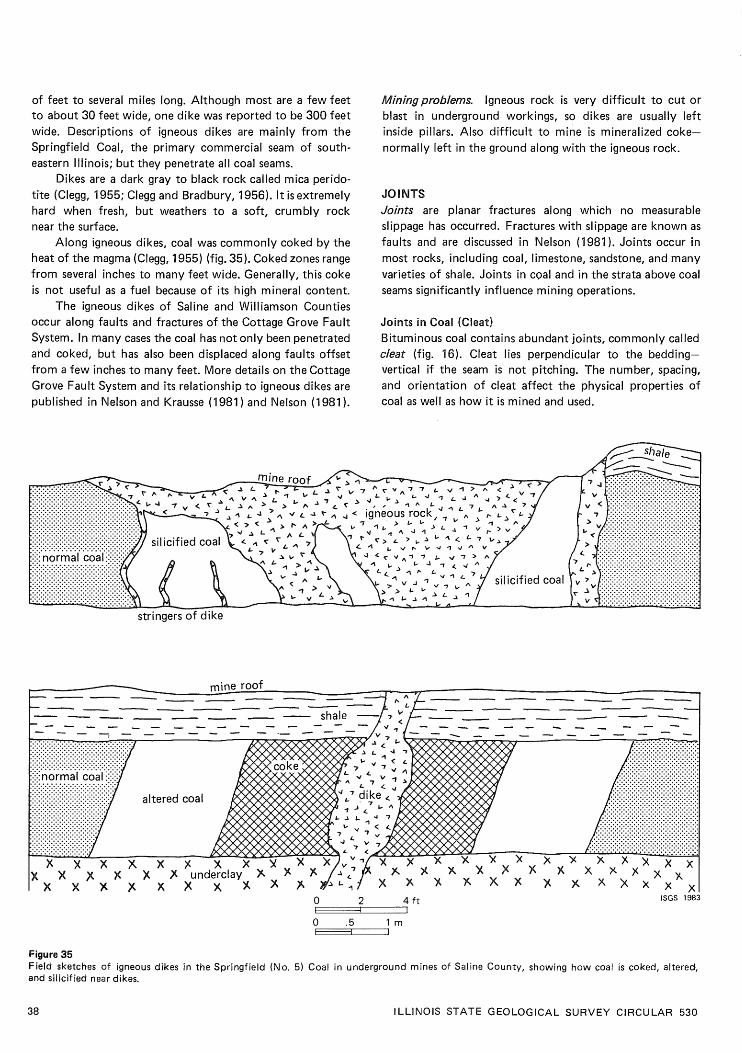
of feet to several miles long. Although most are a few feet to about 30 feet wide, one dike was reported to be 300 feet wide. Descriptions of igneous dikes are mainly from the Springfield Coal, the primary commercial seam of south- eastern Illinois; but they penetrate all coal seams.
Dikes are a dark gray to black rock called mica perido- tite (Clegg, 1955; Clegg and Bradbury, 1956). It i s extremely hard when fresh, but weathers to a soft, crumbly rock near the surface.
Along igneous dikes, coal was commonly coked by the heat of the magma (Clegg, 1955) (fig. 35). Coked zones range from several inches to many feet wide. Generally, this coke is not useful as a fuel because of its high mineral content.
The igneous dikes of Saline and Williamson Counties occur along faults and fractures of the Cottage Grove Fault System. In many cases the coal has not only been penetrated and coked, but has also been displaced along faults offset from a few inches to many feet. More details on the Cottage Grove Fault System and i t s relationship to igneous dikes are published in Nelson and Krausse (1 981 ) and Nelson (1 981 ).
lWiningproblems Igneous rock is very difficult to cut or blast in underground workings, so dikes are usually left inside pillars. Also difficult to mine i s mineralized coke- normally left in the ground along with the igneous rock.
JO l NTS Joints are planar fractures along which no measurable slippage has occurred. Fractures with slippage are known as faults and are discussed in Nelson (1981). Joints occur in most rocks, including coal, limestone, sandstone, and many varieties of shale. Joints in c ~ a l and in the strata above coal seams significantly influence mining operations.
Joints in Coal (Cleat) Bituminous coal contains abundant joints, commonly called cleat (fig. 16). Cleat lies perpendicular to the bedding- vertical if the seam is not pitching. The number, spacing, and orientation of cleat affect the physical properties of coal as well as how it i s mined and used.
stringers of dike
Figure 35 Field sketches of igneous dikes in the Springfield (No. 5) Coal in underground mines of Saline County, showing how coal is coked, altered, and silicified near dikes.
38 I LLlNOlS STATE GEOLOGICAL SURVEY CIRCULAR 530

Figure 36 Joints in the black, fissile Anna Shale above the Herrin (No. 6) Coal. The shale tends to break in large slabs between the parallel joint surfaces. (From Krausse et al., 1979.)
Most coal seams in Illinois contain two intersecting sets of cleat roughly at right angles to each other (fig. 16). The more prominent set of joints, extending fairly con- tinuously through the coal, i s called the face cleat. Con- necting but not penetrating the face cleat is a less prominent set of fractures known as the butt cleat. Together, the face and butt cleat produce the characteristic blocky fracture of bituminous coal. Most coal contains more than two sets of cleat, but the extra sets may not be as obvious.
The terms face and butt cleat come from the days of hand loading. Coal was easier to cut when mined with the prominent cleat parallel and the secondary cleat at right angles to the face, The practice lasted while the mines were mechanized because coal breaks out more uniformly when shot, i f the face cleat i s parallel with the working face. Now that continuous miners do most underground mining, little or no attention is paid to the direction of the cleat.
The spacing of face and butt cleat can vary from a fraction of an inch to as much as 2 feet. The Lower and Upper Block Coals of Indiana were named for the unusually wide spacing of their cleat, allowing the coal to be extracted in large chunks. Block coal formerly was in demand as a fuel for hand-fired furnaces, stoves, and fireplaces (Wier, 1973). In contrast, friable coal contains ten or more joints to the inch, which creates a large amount of dust and slack when mined. This i s less of a disadvantage than it used to be, now that most coal is pulverized for fueling power plants. The fine coal is s t i l l an environmental hazard during mining, handling, and shipping. In Illinois, most coal falls between these two extremes, with fractures spaced roughly % to 4 inches apart.
Miningproblems. Few difficulties in mining, handling, or using Illinois coal have been related to the spacing of cleat, so the subject has received little attention from either industry or scientists.
Ash and sulfur are found in the mineral facings that f i l l the cleat. The most common minerals are calcite, pyrite, various clays, and sphalerite (zinc sulfide) (Cobb e t al., 1980). Generally, the mineral facings are paper thin. They may occur or? face cleat, butt cleat, or both. These impurities are relatively easy to wash out of coal during preparation.
Joints in the Roof In Illinois, vertical jointing is best exhibited in the black, fissile shales that commonly lie directly over coal seams. These shales are characterized by regular jointing with fractures spaced 3 inches to 1 foot apart (fig. 36). Joints in the Anna Shale above the Herrin Coal consistently trend east-northeast over the state; the reason for this orientation is unknown. Occasionally a secondary set of fractures, roughly perpendicular to the main set, is present. Normally, joints affect only the hardest, most brittle shales. They promote slabbing of the lower layers of shale, but do not appear to cause major roof failures (Krausse et al., 1979).
Gray shales, siltstones, sandstones, and limestones are less consistently jointed than black fissile shales. In these rocks, joints are usually spaced many feet apart and seldom start large falls. Exceptions sometimes occur in the vicinity of large faults, where closely spaced joints may extend com- pletely through the roof sequence. The nature and influence of fault-related fractures are discussed in Nelson (1981).
Miningproblems. Vertical joints in the strata above a coal seam influence the stability of the roof. Occasionally, they act as pathways for water and gas to enter underground workings. Joints, however, seem to have fewer detrimental effects on Illinois mining than they do in other American coal fields (Krausse et al., 1979).
For surface operations, joints in the overburden seldom cause problems. Occasionally, massive sandstones or lime- stones above the coal seam are completely penetrated by
GEOLOGIC DISTURBANCES I N ILLINOIS COAL SEAMS

" Coal ball Energy Shale roof
0 100 200 300 400 ft
f - LJ Coal-ball concentration Anna Shale1 Brereton Limestone roof ISGS 1982
Figure 37 Coal balls and roof lithology in an area of Old Ben Mine No. 24 mined by the longwall method. Coal balls occur almost exclusively under the Anna Shale, a marine deposit. (From Bauer and DeMaris, 1982.)
large, widely spaced joints. When the highwall i s aligned more or less parallel with the joints, large blocks of rock may separate without warning and fall into the pit.
COAL BALLS During the Pennsylvanian Period, layers of peat sometimes became saturated shortly after burial with water rich in dissolved minerals. Minerals permeated parts of the peat, turning them into stone before they could turn into coal. Such fossilized peat masses often have a spherical or lens shape; they are known as coal balls.
In the Illinois Basin Coal Field, coal balls have been reported in 17 different seams, including most minable seams (Phillips, Avcin, and Berggren, 1976). Most are over- lain by black shale or limestone, formed from marine- water deposits with a high mineral content. Apparently, the dissolved minerals precipitated to form coal balls.
(Sulfur in seawater is also the source of much sulfur in coal [Gluskoter and Simon, 19681 .) For example, coal balls at Old Ben Mine No. 24 are found only in coal over- lain by or immediately adjacent to the marine, black fissile Anna Shale. Coal overlain by nonmarine Energy Shale contains almost no coal balls (fig. 37). Rarely do coal balls occur in coal topped by gray shale, siltstone, or sand- stone, formed from lake or river deposits. The reason for this relationship is that freshwater contains a lower propor- tion of dissolved minerals than seawater. Also coal overlain by freshwater sediments was protected from later invasions of seawater. Mapping a t Old Ben Mine No. 24 illustrates the general rule that coal balls occur in coal overlain by marine strata (fig. 37).
Most coal balls are composed of calcium carbonate (CaC03 ) and varying amounts of pyrite (FeS2 ) : calcareous coal balls are medium to dark gray or tawny brown; pyritic
ones are golden, brassy, or greenish gray. Another type,
l LLiNOlS STATE GEOLOGICAL SURVEY CIRCULAR 530

Figure 38 Coal ball (about 3 f t long and 1 f t thick) near top of the Herrin (No. 6) Coal in the Orient Mine No. 4, Freeman United Coal Com- pany, Williamson County. The roof is limestone on a thin base of shale.
composed of silica (Si02), i s encountered less often: siliceous coal balls may be gray or black.
Coal balls commonly occur as isolated nodules or lenses scattered through the seam, especially in the upper layers. They may be several inches to several feet in diameter (fig. 38). Occasionally, large masses of coal balls are encoun- tered. Entire seams may be mineralized in areas 100 feet in diameter or larger. The structure may vary from multiple zones of coal balls throughout the coal, to intergrown masses separated by thin stringers of coal, to huge masses of solid rock (fig. 39).
Paleobotanists are greatly interested in coal balls because many contain beautifully preserved remains of plants that grew in coal-forming swamps. In many cases the most minute details of plants, even their cellular struc- ture can be observed microscopically. Such observation is not possible in ordinary coal because coalification destroys plant structure. Discoveries of coal balls should be reported to specialists in studies of coal balls and fossil plants; for instance, T. L. Phillips of the Botany Department a t the University of Illinois. Further research may lead to develop- ment of techniques to predict the occurrence of mineralized peat before mining (DeMaris et al., 1983).
Miningproblems. Both calcareous and siliceous coal balls are extremely hard and dense compared to the surrounding coal; they easily damage drills, miner bits, crushers, and related equipment used in mining and preparation.
Isolated coal balls are only a minor nuisance in mining. Massive coal balls are troublesome, even when encountered in surface mines. Generally loaders can bypass them, but sometimes they must be blasted out or graded over to
Figure 39 In the Herrin Coal at Old Ben Mine No. 24 in Franklin County, multiple zones of coal balls (light gray lenticular pattern) nearly f i l l the seam, from roof to floor: some are intergrown; others are separated by thin layers of coal. (Photo from Phillips, Avcin, and Berggren, 1976.)
allow passage of equipment. In underground mines, massive coal balls are more
serious. An example of an underground mine troubled by coal balls in one part of i t s field i s Old Ben Mine No. 24 in the Herrin Coal of Franklin County. Concentrated masses of coal balls, some more than 100 feet in diameter, were struck in three panels laid out for longwall mining (fig. 37). Repeated damage to the shearer and stage loader (crusher) resulted from mining the large lenses of rock in the coal. Two masses of coal balls were so solidly intergrown that the shearer could not cut them, and the miners had to resort to drilling and blasting to clear out these deposits. The belt entry of one panel had to be relocated to bypass massive coal balls; and two of the three longwall panels were shortened to avoid longwall mining through them (Bauer and DeMaris, 1982).
A t another mine in the Herrin Coal of east-central Illinois, extremely hard, black siliceous coal balls were found in areas of abnormally thin coal (apparently, because it had been partly eroded). Siliceous coal balls form inter- grown masses or layers as much as 2 feet thick in the upper part of the seam. They are very difficult to cut with the continuous miner and must be left in the roof. Coal nearby is abnormally dull, hard, and high in ash. The banding in the coal is distorted and locally destroyed; it contains many lenses and bands of fusain (mineral charcoal ormother coal) and a high proportion of clay as thin lenses, layers, and finely disseminated particles. Probably, the peat was partly eroded, mixed with clay, oxidized somewhat, then min- eralized with silica before it was coalified. The dull, dis- turbed coal i s hard to mine and of little value as a fuel, even where it does not contain siliceous coal balls.
GEOLOGIC DISTURBANCES I N ILLINOIS COAL SEAMS

MISCELLANEOUS Some disturbances in coal seams and neighboring strata do not f i t into the previous discussions. Either they are rare, localized phenomena or common features with minor influence on coal -mining operations.
Glacial Origin Great continental ice sheets invaded Illinois at least four times during the Pleistocene Epoch-the most recent 2 million years or so of the earth's history. Glaciers advanced over northern and central Illinois; and at least one, the Illinoian, extended over almost all the area now underlain by coal -bearing strata. Probably the ice was several thousand feet thick over most of Illinois and exerted enormous pressure on the rocks beneath it. In some places, strata
the weight and movement of ice. In 1908, Udden described intense dislocations in the
Springfield Coal near Peoria. The disturbances encountered in some shallow underground mines were also visible in outcrops and exposures along stream banks. Effects included (1) abrupt thinning or thickening of the seam, (2) sharply folded coal and adjoining strata, (3) rotated masses of bedrock-sometimes completely inverting the coal so that it rested above i t s roof shale, (4) doubled or tripled seams from layers broken and shoved over one another, (5) hori- zontal displacement of coal - bearing strata along large faults, and (6) crushed coal and rocks-sometimes a soft powder that could be scooped by hand. Some disturbances extended over hundreds of acres. Udden concluded that the pressure of movement of Pleistocene glaciers deformed the
near the surface, including coal seams, were disturbed by coal and rocks.
Figure 40 Part of the workings of Peabody Mine No. 10, showing the hill.
42 l LLlNOlS STATE GEOLOGICAL SURVEY CIRCULAR 530

east
vertical exaggeration 2.5 x
50 100ft
Figure 41 Cross section of the hill in the 5% West Mains off the Main East in Peabody Mine No. 10, Christian County.
Miningproblems. Glacial disturbances, which are near-sur- face features, are not usually encountered underground today because few modern operators mine as close to the surface as those early miners. Surface mines, however, may have to contend with glacial disruptions wherever the bed- rock covering the coal i s thin. Strip mining deformed coal, such as Udden described, would be expensive; yet much surface mining has taken place in Illinois, and few glacially caused disturbances have been encountered.
The Hill at Peabody Mine No. 10 The hill at Peabody Mine No. 10 in Christian County is actually an elongate trough or valley in the Herrin (No. 6) Coal, trending roughly north-south for at least 5000 feet; i t s southern end has not been located (fig. 40). The coal in the trough is 20 to 30 feet lower than neighboring coal.
In cross section, the hill i s quite symmetrical (fig. 41). Coal slopes gently into the trough on both sides for several hundred feet, then abruptly pitches downward at a 10- to 15-degree angle. The floor of the trough is roughly level and 150 to 200 feet wide. Also, the seam thickens as it dips into the trough, attaining up to twice its normal size. This thicker coal appears to contain more shaly partings than normal.
The roof strata also change in thickness and character in the hill (fig. 41 ). A t the bottom of the valley, coal is overlain by 8 to 10 feet of gray shale (probably Energy Shale). The shale pinches out on the flanks of the trough, where the coal i s overlain by black, fissile Anna Shale that thins as the coal rises. Away from the hill, the Brereton Limestone lies directly on the coal. A channel filled with Anvil Rock Sandstone follows the trough and has eroded the Anna Shale and Brereton Limestone. Although erosion of the coal was not observed, the base of the channel i s scoured into the Energy Shale.
The hypothetical origin of the hill is shown in figure 42. A channel filled with easily compactable sediments such as mud and peat i s believed to underlie the trough. As sedi- ments compacted in the channel, an elongate depression formed, into which the Herrin Coal and overlying sediments were deposited more thickly than normal. After the Brere- ton Limestone formed, the depression persisted, providing a
GEOLOGIC DISTURBANCES I N l LLlNOlS COAL SEAMS
path for an Anvil Rock channel. To confirm this theory, drilling beneath the Herrin Coal in the trough is needed.
Other coal-filled channels in Illinois include the Cardiff Coal in northeastern Livingston County (Cady, 1915), the Kerton Creek Coal in Fulton County (Wanless, 1957), and the Roodhouse Coal in Greene County (Willman e t al., 1975). All are examples of thick canneloid coals localized in narrow channel-fill deposits. Similar occurrences also have been reported from coal mines in England (Elliott, 1965).
Miningproblems. Mining along the hill in Mine No. 10 is difficult despite the unusually thick coal found in it. Steep dips in the coal on the flanks of the trough, unstable roof in the Energy Shale, and seepage of groundwater from the Anvil Rock Sandstone increase the eXpehSe and trouble in mining. So the Peabody Coal Company has left some coal unmined.
Concretions Large spherical or oval masses of hard rock in the shales overlying coal seams are known as concretions (fig. 43). Commonly composed of calcite (calcium carbonate) or siderite (iron carbonate), many concretions also contain pyrite and other sulfides. They can be as much as 3 or 4 feet in diameter and weigh hundreds of pounds. Concre- tions probably formed by chemical precipitation of min- erals around a nucleus, such as a bit of organic matter in mud-before the mud hardened into shale.
Most concretions occur in black fissile shales such as the Anna Shale above the Herrin Coal, but they also appear in gray or mottled shales and siltstones. Since they are concentrated in the lowermost layers of the roof, they may protrude several inches into the coal (fig. 43).
Mining problems. Large masses of intergrown concretions at the coal -roof contact can dull miner bits. Aside from this problem, concretions are a hazard in the roof because they generally are surrounded by slickensides that allow them to separate readily from the shale (Krausse et al., 1979a, 1979b). However, concretions rank fairly low on the l i s t of geologic hazards with which coal miners contend.
43

c. More deposits covered the channel. The channel-fill materials
. . . . . . . . . . . . . - . . . . - . _ . . . . . . . . . . . . . . . . ' . . . .
compacted more than the surrounding materials, so a trough devel-
. . . . . . . . - . . . . . . . . . . . . . . . . . . . . . . , . . . . .
. . . . . . . . . . . . - . . . . . . . . . . . . . . . . . . . . . . . . . . - - . . . .
d. The Herrin peat was deposited, accumulating more thickly in the trough than along the sides.
a. Long before development of Herrin (No. 6) Coal, a stream cut a b. The channel filled with soft, compressible sediments such as mud channel into sediments. and peat.
oped above the buried channel.
- - . - - - .
e. Compaction of sediments continued; sag (trough) persisted. Then f. As the region was flooded by a shallow sea, lime mud (Brereton the Energy and Anna Shale sediments were deposited in it. Limestone) was laid down, covering shales and peat.
g. The ocean receded, and a new stream began to flow along the h. Additional sediments were laid down and became compacted and trough, cutting a channel to be filled with sand (Anvil Rock Sand- lithified, resulting in today's situation. stone).
ISGS 1983
Figure 42 Theory of how the "hill" formed.
l LLlNOlS STATE GEOLOGICAL SURVEY CIRCULAR 530

Figure Large concretion in the black, fissile Anna Shale above the Herrin (No. 6) Coal. Note that the top of the coal has been pu slightly under the concretion due to differential compaction.
shed downward
Figure 44 Fossil tree stump or kettlebottom (about 2 f t diameter) in the shale above a coal seam. The bark of the stump became coal; the hollow center filled with mud that became shale.
centers of the stumps have been filled with mud and s i l t . Fossil tree stumps, sometimes called kettlebottoms, are The central plug of shale separates easily from the found in the roof of a coal seam (fig. 44). They are charac- coalified bark and can be a minor hazard in underground teristic of gray shales and siltstones, such as the Dykersburg operations. Where fossil tree stumps are numerous, they and Energy Shales, which formed from sediments that buried make the upper surface of the coal slightly irregular; but forests so rapidly the trees had no chance to decay. Usually aside from the danger of their falling from the roof, they only the bark or rind has been preserved as coal; the hollow do not significantly influence coal mining.
GEOLOGIC DISTURBANCES IN ILLINOIS COAL SEAMS 45
This report would not have been possible without the cooperation of the lllinois coal industry. Worthy of special mention are M. V. Harrell, William Mullins, Roger Nance, and Pat Peterson of Freeman United Coal Mining Company; Douglas Dwosh and Phil Rogers of Inland Steel Coal Company; Floyd Lee of Lee Coal Company; Lester Grogan of Old Ben Coal Company; Randy Dempsey, M. E. Hopkins, and Thomas Gilchrist of Peabody Coal Company; Erich Egli and Robert Gullic of Sahara Coal Company; and Michael Nowo- bilski of Zeigler Coal Comapny. I am grateful to many present and former members of the ISGS Coal Section, who took part in mapping and studies-especially Robert A. Bauer, Heinz H. Damberger, Stephen K. Danner, Philip J. DeMaris, H.-F. Krausse, and John Popp. I also thank the reviewers of the manuscript: Dwain J. Berggren, Heinz H. Damberger, Philip J. DeMaris, and Robert H. Gilkeson.
REFERENCES Acker, J. R., and L. H. Kumamoto, 1981, High resolution seismic
exploration at Peabody Coal Company Mine 10: l llinois Mining Institute, Springfield, 1 L, October 22, 1981.
Allgaier, G. J., and M. E. Hopkins, 1975, Reserves of the Herrin (No. 6) Coal in southeastern Illinois: lllinois State Geological Survey Circular 489, 31 p.
Andros, S. D., 1914, Coal mining practice in District VII: lllinois State Geological Survey Cooperative Coal Mining lnvestigations Bulletin 4, 53 p.
Ashley, G. H., 1928, Bituminous coal fields of Pennsylvania; general information on coal: Pennsylvania Geological Survey, 4th Series Bulletin M6, part 1.
Ault, C. H., D. M. Sullivan, and G. F. Tanner, 1980, Faulting in Posey and Gibson Counties, Indiana: Proceedings of the lndiana Academy of Science, v. 89, p. 275-289.
Bauer, R. A., and P. J. DeMaris, 1982, Geologic investigation of roof and floor strata: longwall demonstration, Old Ben Mine No. 24, Final Technical Report: Part 1, U.S. DOE Contract ET-76-G- 01 -9007, lllinois State Geological Survey ContractIGrant Report: 1982-2,49 p.
Beerbower, J. R., 1964, Cyclothems and cyclic depositional mecha- nisms in alluvial plain sedimentation, in Merriam, D. F . [ed.], Symposium on Cyclic Sedimentation, State Geological Survey of Kansas, Bulletin 169, v. 1, p. 31 -47.
Bretz, J. H., 1950, Origin of the filled sink-structures and circle deposits of Missouri: Bulletin of the Geological Society of America, v. 61, p. 789-834.
Bretz, J. H., and S. E. Harris, Jr., 1961, Caves of Illinois: lllinois State Geological Survey Report of lnvestigations 215, 87 p.
Cady, G. H., 1915, Coal resources of District I (longwall): lllinois Geological Survey Cooperative Coal Mining lnvestigations Bulletin 10, 149 p.
Cady, G. H., 1921, Coal resources of District IV: l llinois Geological Survey Cooperative Coal Mining lnvestigations Bulletin 26, 247 p.
Cady, G. H., 1935, Some evidence of shrinkage of certain lllinois coal beds since their burial: lllinois State Geological Survey open file manuscript 43, p. 8- 12.
Clegg, K. E., 1955, Metamorphism of coal by peridotite dikes in southern Illinois: l llinois Geological Survey Report of I nvesti- gations 1 78, 18 p.
Clegg, K. E., and J. C. Bradbury, 1956, Igneous intrusive rocks in l llinois and their economic significance: l llinois Geological Survey Report of Investigations 197, 19 p.
Cobb, J. C., J. D. Steele, C. G. Treworgy, and J. F. Ashby, 1980, The abundance of zinc and cadmium in sphalerite-bearing coals in Illinois: lllinois State Geological Survey, lllinois Mineral Notes 74, 28 p.
Coleman, J. M., 1976, Deltas: processes of deposition and models for exploration: Continuing Education Publication Co., Inc., Champaign, l L, 102 p.
Collinson, C., and R. Skartvedt, 1960, Pennsylvanian plant fossils of Illinois: l llinois State Geological Survey Educational Series 6, 35 p.
Coon, J. B., J. T. Reed, W. L. Chapman, and D. E. Dunster, 1979, Surface seismic methods applied to coal -mining problems: AAPG Annual Convention, Houston, TX, April 1-4, 1979.
Daly, T. E., 1979, High-resolution seismic methods in coal explor- ation: AAPG Annual Convention, Houston, TX, April 1-4, 1979.
Damberger, H. H., 1970, Clastic dikes and related impurities in Herrin (No. 6) and Springfield (No. 5) Coals of the lllinois Basin, in Depositional Environments in Parts of the Carbon- dale Formation-Western and Northern I ll inois: l llinois State Geological Survey Guidebook 8, p. 1 1 1 - 1 19.
Damberger, H. H., 1973, Physical properties of the lllinois Herrin (No. 6) Coal before burial, as inferred from earthquake- induced disturbances: Compte Rendu, Seventh International Congress of Carboniferous Stratigraphy and Geology, v. 2, p. 341 -350.
Damberger, H. H., W. J. Nelson, and H.-F. Krausse, 1980, Effect of geology on roof stability in room-and-pillar mines in the Herrin (No. 6) Coal of Illinois, in Chugh, Y. P., and A. Van Besien [eds.] , Proceedings, First Conference on Ground Control Problems in the lllinois Coal Basin, Southern Illinois University, Carbondale, I L, June 1980, p. 14-32; Illinois State Geological Survey Reprint 198OP.
DeMaris, P. J., W. A. DiMichele, and W. J. Nelson, 1979, A com- pression flora associated with channel-fill sediments above the Herrin (No. 6) Coal: Abstract, Ninth l nternational Congress of Carboniferous Stratigraphy and Geology.
DeMaris, P. J., R. A. Bauer, R. A. Cahill, and H. H. Damberger, 1983, Geologic investigation of roof and floor strata: longwall demonstration, Old Ben Mine No. 24. Prediction of coal balls in the Herrin Coal: lllinois State Geological Survey Contract/ Grant Report 1983-2,69 p.
Deshowitz, M. P., 1979, Stratigraphy, paleoecology and environ- ments of deposition of the Energy Shale (Pennsylvanian) in southern Illinois: Master's thesis, Department of Geology, Southern l llinois University, Carbondale, 120 p.
Edmunds, W. E., and E. F. Koppe, 1968, Coal in Pennsylvania: Pennsylvania Geological Survey Educational Series 7, 29 p.
Edwards, M. J., R. L. Langenheim, Jr., W. J. Nelson, and C. T. Ledvina, 1979, Lithologic patterns in the Energy Shale Mem- ber and the origin of "rolls" in the Herrin (No. 6) Coal Member, Pennsylvanian, in the Orient No. 6 Mine, Jefferson County, Illinois: Journal of Sedimentary Petrology, v. 49, no. 2, 1979.
Elliott, R. E., 1965, Swilleys in the coal measuresof Nottinghamshire interpreted as palaeoriver courses: Mercian Geologist, v. 1, p. 133-142.
Ferguson, H. F., 1967, Valley stress release in theAllegheny Plateau: Association, Engineering Geology Bulletin, v.4, no. 1, p. 63-69.
Friedman, S. A., 1955, Split and channel sandstone cutout in Coal V in Dresser area, Vigo County, Indiana: lndiana Academy of Science, p. 165- 168.
Gluskoter, H. J., and M. E. Hopkins, 1970, Distribution of sulfur in lllinois coals, in Depositional Environments in Parts of the Carbondale Formation-Western and Northern Illinois: lllinois State Geological Survey Guidebook 8, p. 89-95.
Gluskoter, H. J., and J. A. Simon, 1968, Sulfur in lllinois coals: l llinois State Geological Survey Circular 432, 28 p.
Heckel, P. H., 1977, Origin of phosphatic black shale facies in Pennsylvanian cyclotherrns of mid-continent North America: AAPG Bulletin, v. 61, p. 1045- 1068.
ILLINOIS STATE GEOLOGICAL SURVEY CIRCULAR 530

Hopkins, M. E., 1958, Geology and petrology of the Anvil Rock Sandstone of southern Illinois: Illinois State Geological Survey Circular 256, 49 p.
Hopkins, M. E., R. B. Nance, and C. G. Treworgy, 1979, Mining geology of lllinois coal deposits, in Depositional and Structural History of the Pennsylvanian System of the lllinois Basin, Part 2: Field Trip 9, Ninth International Congress of Carboni- ferous Stratigraphy and Geology, p. 142-151.
Hunt, S. R., R. A. Bauer, and P. B. DuMontelle, in press, Subsidence due to coal mining in the l llinois Basin Coal Field: U.S. Depart- ment of Energy, Final Contract Report ET-78-G-01-3085.
Johnson, D. O., 1972, Stratigraphic analysis of the interval between the Herrin (No. 6) Coal and the Piasa Limestone in southwestern Illinois: Ph.D. dissertation, University of Illinois, Urbana, 105 p.
Kosanke, R. M., J. A. Simon, H. R. Wanless, and H. B. Willman, 1960, Classification of the Pennsylvanian strata of Illinois: l llinois State Geological Survey Report of l nvestigations 21 4, 84 p.
Krausse, H.-F., H. H. Damberger, W. J. Nelson, S. R. Hunt, C. T. Ledvina, C. G. Treworgy, and W. A. White, 1979a, Roof strata of the Herrin (No. 6) Coal and associated rock in Illinois-a summary report: lllinois State Geological Survey Mineral Notes 72, 54 p.
Krausse, H.-F., H. H. Damberger, W. J. Nelson, S. R. Hunt, C. T. Ledvina, C. G. Treworgy, and W. A. White, 1979b, Engineering study of structural geologic features of the Herrin (No. 6) Coal and associated rock in Illinois. Volume 2: lllinois State Geo- logical Survey, Final Contract Report to U.S. Bureau of Mines H0242017, 205 p.
Kravits, C. M., and J. C. Crelling, 1981, Effects of overbank deposi- tion on the quality and maceral composition of the Herrin (No. 6) Coal (Pennsylvanian) of southern Illinois: International Journal of Coal Geology, v. 1, p. 195-212.
McCabe, K., 1978, Discontinuities that constitute roof control and other safety hazards: Proceedings, Coal-Seam Discontinuities Symposium, D'Appolonia, Pittsburgh, PA, 18 p.
Merriam, D. F. Led.], 1964, Symposium on cyclic sedimentation: State Geological Survey of Kansas Bulletin 169, v. 1 and 2, 636 p.
Nelson, W. J., 1981, Faults and their effect on coal mining in Illinois: Illinois State Geological Survey Circular 523, 38 p.
Nelson, W. J., and H.-F. Krausse, 1981, The Cottage Grove Fault System in southern Illinois: l llinois State Geological Survey Circular 522, 65 p.
Nelson, W. J., and R. B. Nance, 1980, Geological mapping of roof conditions, Crown I I Mine, Macoupin County, Illinois: Society of Mining Engineers of AIME, Preprint 80-308: lllinois State Geological Survey Reprint 1981A, 9 p.
Payne, J. N., and G. H. Cady, 1944, Structure of Herrin (No. 6) Coal Bed in Christian and Montgomery Counties and adjacent parts of Fayette, Macon, Sangamon, and Shelby Counties: Illinois State Geological Survey Circular 105, 57 p.
Phillips, T. L., M. J. Avcin, and D. J. Berggren, 1976, Fossil peat from the lllinois Basin: lllinois State Geological Survey Educa- tional Series 11, 39 p.
Piskin, K., and R. E. Bergstrom, 1975, Glacial drift in Illinois: thickness and character: lllinois Geological Survey Circular 490, 35 p.
Potter, P. E., and R. F . Mast, 1963, Sedimentary structures, sand
shape fabrics, and permeability: Journal of Geology, v. 71, no. 3, p. 441 -471.
Savage, T. E., 1910, Clay seams or so-called horsebacks near Spring- field, Illinois: Economic Geology, v. 5, p. 178- 187.
Saxena, R. S., 1976, Modern Mississippi Delta-depositional envi- ronments and processes: AAPG ISEPM Field Trip Guide Book-Mississippi Delta Flight, New Orleans, LA, May 23-26, 1976, p. 89-102.
Simon, J. A., 1956, Sandstone cut-outs in Christian, Montgomery, Sangamon, and Macoupin Counties: lllinois State Geological Survey unpublished report, 3 p.
Treworgy, C. G., 1980, Seelyville Coal-a major unexploited seam in Illinois: Abstracts, AAPG-SEPM-EMD Annual Convention, Denver, Colorado, June 8- 11, 1980, p. 130.
Treworgy, C. G., 1981, The Seelyville Coal-a major unexploited seam in Illinois: l llinois State Geological Survey Mineral Notes 80, 1 1 p.
Treworgy, C. G., and R. J. Jacobson, 1979, Paleoenvironments and distribution of low-sulfur coal in Illinois: Abstract, Ninth International Congress of Carboniferous Geology and Strati-
graphy. Udden, J. A., 1908, Defects in the No. 5 Coal at Peoria: lllinois
Geological Survey Bulletin 8, p. 255-267. Udden, J. A., 1912, Geology and mineral resources of the Peoria
quadrangle, Illinois: U.S. Geological Survey Bulletin 506, 103 p. Wang, F.-D., D. M. Ropchan, and M.-C. Sun, 1974, Structural
analysis of a coal mine opening in clastic, multilayered material: U.S. Bureau of Mines Report of Investigations 7845, 36 p.
Wanless, H. R., and J. M. Weller, 1932, Correlation and extent of Pennsylvanian cyclothems: GSA Bulletin, v. 32, no. 4, p. 1003- 1016.
Wanless, H. R., 1952, Studies of field relations of coal beds: Nova Scotia Department of Mines, Second Conference on Origin and Constitution of Coal, Crystal Cliffs, Nova Scotia, p. 148- 180.
Wanless, H. R., 1957, Geology and mineral resources of the Beards- town, G lasford, Havana, and Vermont Quadrangles: l llinois State Geological Survey Bulletin 82, 233 p.
Wanless, H. R., and F. P. Shepard, 1936, Sea level and climatic changes related to late Paleozoic cycles: GSA Bulletin, v. 47, p. 1177-1206; 2008-2014.
Weller, J. M., 1956, Argument for diastrophic control of late Paleo- zoic cyclothems: AAPG Bulletin, v. 40, no. 1, p. 17-50.
Wheeler, H. E., and H. H. Murray, 1957, Base-level control patterns in cyclothemic sedimentation: AAPG Bulletin, v. 41, no. 9, p. 1985-201 1; discussion by J. M. Weller, H. E. Wheeler, and H. H. Murray, v. 42, no. 2, p. 442-452.
Wier, C. E., 1973, Coal resources of Indiana: Indiana Geological Survey Bulletin 42-1, 40 p.
Willman, H. B., and J. C. Frye, 1970, Pleistocene stratigraphy of Illinois: Illinois State Geological Survey Bulletin 94, 204 p.
Willman, H. B., E. Atherton, T. C. Buschbach, C. Collinson, J. C. Frye, M. E. Hopkins, J. A. Lineback, and J. A. Simon, 1975, Handbook of l llinois stratigraphy: lllinois State Geological Survey Bulletin 95, 261 p.
Wilson, W. B., 1916, The origin of clay slips: Economic Geology, V. 9, p. 381 -389.
Zangerl, R., and E. S. Richardson, 1963, The paleoecological history of two Pennsylvanian black shales: Chicago Natural History Museum, Fieldiana: Geological Memoir, v. 4, 352 p.
GEOLOGIC DISTURBANCES IN ILLINOIS COAL SEAMS