Embed Size (px)
Citation preview

Geological and mathematical framework for failure modes
in granular rock
Atilla Aydina,*, Ronaldo I. Borjab, Peter Eichhubla,1
aDepartment of Geological and Environmental Sciences, Stanford University, Stanford, CA 94305, USAbDepartment of Civil and Environmental Engineering, Stanford University, Stanford, CA 94305, USA
Received 3 November 2004; received in revised form 19 July 2005; accepted 28 July 2005
Available online 18 October 2005
Abstract
We synthesize all the available data on failure processes in granular rock and provide a geological framework for the corresponding
structures. We describe two categories: (1) sharp discontinuities made up of two surfaces similar to elastic crack models, and (2) tabular
structures resulting from strain localization into narrow bands. Each of these categories includes types predominated by shear and/or
volumetric deformation. While shear failure can be in two different modes as sliding and tearing, the volumetric failure has two diametrically
opposite types: compaction (contraction) and dilation (extension). Thus, we distinguish among bands predominantly by shearing, shortening,
and extension. Slip surfaces, pressure solution surfaces, and joints represent corresponding sharp discontinuities. A survey of observations
and measurements from naturally occurring structures indicates that although isochoric shear and pure volumetric deformation types
represent end members, a complete spectrum of combined shear and volumetric deformation occurs in nature. Field observations also show
that sharp structures overlap older narrow tabular structures in the same rock. This switch in failure modes is attributed to changing rock
rheology and/or loading conditions.
In the mathematical modeling, we focus on the strain localization into narrow tabular bands using classical bifurcation theory combined
with nonlinear continuum mechanics and plasticity. We formulate a family of three invariant plasticity models with a compression cap and
capture the entire spectrum of failure of geomaterials. In addition, we draw an analogy between the concepts of ‘strong’ and ‘sharp’
discontinuity and classic elastic crack representations to complement the mathematical treatment of the failure modes.
q 2005 Elsevier Ltd. All rights reserved.
Keywords: Failure modes; Deformation bands; Shear bands; Compaction bands; Dilation bands; Fracturing of sandstone
1. Introduction
Failure of soil, sand, and granular rock under natural and
laboratory loading conditions involves a variety of
micromechanical processes (Wong et al., 1997) that
produce several geometrically, kinematically, and texturally
distinct types of natural structures (Davatzes and Aydin,
2004). This paper provides a geological and mathematical
framework for these failure processes and their structural
products. The simplest of common structures is made up
0191-8141/$ - see front matter q 2005 Elsevier Ltd. All rights reserved.
doi:10.1016/j.jsg.2005.07.008
* Corresponding author.
E-mail address: [email protected] (A. Aydin).1 Present address: Department of Physical and Life Sciences, Texas
A&M University-Corpus Christi, Corpus Christi, TX 78412, USA.
two subparallel surfaces. Joints, for example, fall into this
category (Pollard and Aydin, 1988). Shear fractures or faults
are often idealized by relative sliding of two surfaces in
frictional contact (Jaeger and Cook, 1979) and are
represented by elastic crack models (Pollard and Segall,
1987). Another category of structures resulting from failure
in porous granular rock is a narrow tabular zone of localized
strain (Friedman and Logan, 1973; Engelder, 1974) referred
to as a deformation band (Aydin, 1978). The most common
mode in this category is shear bands characterized
predominantly by shearing with either minor compaction
or minor dilation (Antonellini et al., 1994a). Shearing with
no or very little volume change (isochoric or simple shear),
and pure compaction/dilation with no macroscopic shearing
also exist and represent the basic end members. Defor-
mation bands with predominantly volume change have been
reported from field studies (Hill, 1989; Antonellini et al.,
Journal of Structural Geology 28 (2006) 83–98
www.elsevier.com/locate/jsg

A. Aydin et al. / Journal of Structural Geology 28 (2006) 83–9884
1994a; Cakir and Aydin, 1994; Mollema and Antonellini,
1996; Sternlof and Pollard, 2001; Du Bernard et al., 2002).
Some of these localization phenomena were successfully
simulated in the laboratory (Dunn et al., 1973; Olsson, 1999;
Mair et al., 2000; Haimson, 2001; Wong et al., 2001) and
were modeled theoretically (Rudnicki and Rice, 1975;
Aydin and Johnson, 1983; Issen and Rudnicki, 2000;
Besuelle and Rudnicki, 2004; Borja and Aydin, 2004).
The first part of this paper synthesizes the available
information in the literature and provides a geological
framework for the entire spectrum of failure modes and
related structures in granular rock. The second part provides
a brief geomechanical framework for these features for the
purpose of introducing a theoretical foundation for the range
of the structures described earlier.
Fig. 1. (a) Idealized shear, compaction, and dilation modes. (b) Trends for
volume change within shear bands with respect to the parent rock. From
Aydin (1978), Antonellini and Aydin (1994) and Antonellini et al. (1994a).
(c) Trends for volume change within compaction and dilation bands. Based
on unpublished data of Antonellini, Aydin, Pollard, and D’Onfro and data
from Mollema and Antonellini (1996) and Du Bernard et al. (2002).
2. Classification of failure structures in sandstone
We propose a broad classification of failure modes in
granular rock, which includes two major categories and
several subdivisions (Fig. 1a):
(1) Deformation bands
(1.1) Shear deformation bands
(1.1.1) Isochoric shear bands
(1.1.2) Compactive shear bands
(1.1.3) Dilatant shear bands
(1.2) Volumetric deformation bands
(1.2.1) Compaction bands
(1.2.2) Dilation bands
(2) Sharp discontinuities
(2.1) Fractures with predominantly shearing/slip
surfaces
(2.2) Discontinuities with predominantly volumetric
deformation
(2.2.1) Joints (dilatant/opening fractures)
(2.2.2) Pressure solution surfaces
(compaction/closing fractures)
The first category in (1) encompasses structures that
form by localization of strain into narrow tabular bands.
These narrow zones of shearing and volumetric defor-
mation are called deformation bands (Aydin, 1978)
following the use of the term in the engineering literature
for localized failure zones (Argon, 1975; Rudnicki and
Rice, 1975). The same structures are sometimes called
Luders’ bands (Friedman and Logan, 1973; Olsson,
2000) or granulation seams (Pittman, 1981). We here
consider two types of deformation bands (Fig. 1a) based
on their kinematic attributes: (1) bands predominated by
shearing, referred to as shear bands in this paper for
simplicity (Figs. 1a and b and 2a), and (2) bands
predominated by volumetric deformation (Fig. 1a and c).
The latter group can be subdivided into compaction
bands that are characterized by a volume decrease with
respect to the undeformed parent rock and dilation bands
that are characterized by a volume increase (Fig. 1c).
Shear bands may have either dilatant or compactive
volumetric deformation. Without being specific on the
relative magnitudes of shear and volumetric components
within a band, we rely on the presence of a noticeable
shear displacement gradient across the band for identi-
fication of shear bands.
Sharp discontinuities are initially made up of two
surfaces that move either parallel or perpendicular to
the surfaces. If the movement of the two surfaces is
perpendicular to each other, it may be either away from,
or toward, each other (opening or mode-I and closing or
anti-crack, respectively). If the movement of the
surfaces is parallel to each other, the products are the
same as the idealized concept of shear fractures (Pollard
and Segall, 1987) that grow in-plane either in sliding

Fig. 2. (a) Outcrop photo showing a shear band (arrow) in Entrada sandstone, San Rafael Desert, Utah. The band shows a few mm left lateral slip. (b) Thin
section image of a shear band (arrow) marked by a smaller grain size (i.e. cataclasis) in the Entrada Sandstone in San Rafael Desert. (c) A shear band without
cataclasis in unconsolidated sediments, McKinleyville, northern California. (d) Outcrop photo of a zone of shear bands in Entrada sandstone, San Rafael
Desert, Utah. Inset shows schematically lateral widening of a deformation band zone. Note hammer for scale. (e) Outcrop photo of a network of shear bands
and zones of shear bands in San Rafael Desert, Utah.
A. Aydin et al. / Journal of Structural Geology 28 (2006) 83–98 85
mode (mode-II) or tearing mode (mode-III). Out of
plane growth in any combination of one of these modes
with opening or closing (mixed modes) is also possible.
Thus, sharp discontinuities are initially similar to the
elastic crack concepts with the caveat that progressive
sliding will eventually produce accompanying defor-
mation adjacent to the sliding surfaces.
3. Micromechanics of failure in deformation bands
The nature of deformation within individual bands is
controlled by textural properties of the parent rock. Typical
granular rocks are made up of grains, pores, and cement.
Deformation of these rocks involves change in shape and
size of one or more of these constitutive elements (Fig. 3).

Fig. 3. (a) Image of initial grain fractures in sandstone. (b) Grain size distribution in shear bands with varying amounts of strain compared with undeformed
sandstone. From Mair et al. (2000). (c) Plots showing the relationship between porosity and confining pressure for cemented and non-cemented granular
material. From Dvorkin and Nur (1996). (d) Dependence of M-modulus (the bulk density of aggregate times the square of P-wave velocity) on porosity for
various effective pressures. From Dvorkin and Nur (1996).
A. Aydin et al. / Journal of Structural Geology 28 (2006) 83–9886
Among these three elements, grains form the skeleton of a
granular rock. The strength of this skeleton depends on the
strength of constituting grains and the nature of cement
supporting the grains. Grain mineral composition plays an
important role in failure processes due to differences in
shape, strength, susceptibility to cleavage fracture, and
chemical stability. Grains deform in three basic modes: (1)
translation and rotation, (2) dissolution, and (3) internal
strain dominated by fracturing in brittle states. Relative
displacement and rotation of intact grains and fracturing of
grains in porous sandstone are primarily controlled by the
Hertzian grain-to-grain interaction (Gallagher, 1987; Zhang
et al., 1990). Dissolution is generally dependent on the
overburden thickness or the burial depth (Bjørlykke and
Høeg, 1997). If the stresses at grain contacts exceed the
tensile strength of the grains or the fracture toughness in
general, they break, leading to fragmentation and comminu-
tion (Fig. 3a and b), which are elements associated with
cataclastic deformation. Pores impact volumetric defor-
mation and control the strength of rock. They act as flaws
and concentrate stresses that may lead to eventual failure by
pore growth and coalescence (Berg, 1970, 1972; Antonellini
et al., 1994a; Du Bernard et al., 2002) or pore collapse
(Aydin, 1978; Curran and Corrall, 1979). In addition, pores
store fluids and thus facilitate transmission of forces to the
skeleton in high fluid pressure environments. It has been
well known, based on the effective stress law, that rocks
under a high pore fluid pressure are considerably weaker
(Hubbert and Rubey, 1959).
Following the principles summarized in the paragraph
above, intergrain sliding (grain translation and rotation),
grain fracturing, pore volume change, and pressure solution
appear to be the fundamental micromechanical processes
that characterize the failure modes and their structural
products in granular rocks under upper crustal conditions.
Grain fractures (Fig. 3a) leading to grain size reduction
(Fig. 3b) and changes in pore volume by either pore collapse
or diagenetic processes (Figs. 1a–c and 3c) are the two
quantities that can readily be identified and measured.
However, intergrain movements are very difficult to detect
in granular rock because of the lack of pre-existing markers.
All micromechanical processes are greatly influenced by
diagenetic reactions that affected the host rock prior to
deformation (Groshong, 1988; Bjørlykke and Høeg, 1997).
Cementation and dissolution reactions control the amount,
distribution, shape, and strength of cement and are therefore
crucial in the failure processes in granular rocks. Cement
exerts resistance to intergranular movement and distributes
contact forces thereby reducing the stress concentration
leading to grain breakage (Bernabe et al., 1992; Dvorkin and
Nur, 1996; Shah and Wong, 1997; Wilson et al., 2003).
With increasing burial depth and cementation, the defor-
mation behavior of granular materials thus changes. General
trends lead from localized tabular modes of elastic/plastic

A. Aydin et al. / Journal of Structural Geology 28 (2006) 83–98 87
deformation to dilatant and sharp modes of elastic
deformation with increasing mechanical compaction
and diagenetic porosity reduction. These trends correspond
to the change from a contact-based Hertzian constitutive
behavior to that of a solid framework with decreasing
porosity as expressed in a gradual increase in M-modulus
(Fig. 3d) (Dvorkin and Nur, 1996). M-modulus is rV2p ,
where r is the bulk density of the aggregate and Vp is the
P-wave velocity.
These general depth trends could potentially be reversed
due to dissolution of framework minerals and of earlier pore
cement leading to the creation of secondary porosity that
may again bring up pore controlled stress concentrations
and may allow compactive modes of deformation localiz-
ation at depth.
4. Shear bands
The diagnostic feature of shear bands is a macroscopic
shear offset across a tabular zone of finite small width with
respect to the other two dimensions (Fig. 2a). Shear offset
can be determined by previously continuous markers such
as beds or older shear bands. Shear bands in granular rocks
have limited offsets on the order of a few millimeters to
centimeters (Engelder, 1974; Antonellini et al., 1994a;
Fossen and Hesthammer, 1997). The average shear strain
calculated from these quantities is on the order of unity
(Aydin, 1978). The length dimension of single shear bands
is also limited to less than 100 m (Fossen and Hesthammer,
1997). Therefore, it is necessary to form new shear bands in
order to widen (or lengthen) a shear band structure in a
manner schematically illustrated by the inset in Fig. 2d
(Aydin and Johnson, 1978). This process leads to the
formation of a zone of shear bands, which is composed of a
number of closely spaced, subparallel distinct shear bands
(Fig. 2d). Well-developed shear zones such as those in
Fig. 2d are associated with a slip surface that accommodates
a large magnitude of slip and marks the appearance of a
sharp discontinuity along usually one side of a zone of shear
bands. Each of these elements may occur in a network
composed of two or more sets (Fig. 2e). Shear bands and
shear band zones are typically more resistant to weathering
thus forming spectacular geomorphic features in the field
(Aydin and Johnson, 1978; Davis, 1999).
A thin section view of a shear band (Fig. 2b and c) shows
evidence for micromechanical processes responsible for its
formation. Grain fracturing (Fig. 3a) can be detected in
initial stages where the grains are damaged but not yet
demolished. In more advanced stages of deformation, grain
fracturing and grain crushing are reflected by grain size
reduction or comminution (Fig. 3b) and change of grain
shape within the localized zone of deformation. Typically,
intense deformation results in broadening of the grain size
distribution within shear bands (Aydin, 1978; Menendez
et al., 1996; Mair et al., 2000; DiGiovanni et al., in press)
due to increase in the number of smaller grains (Fig. 3b).
These processes as well as other textural and diagenetic
changes are usually referred to as ‘cataclasis’ (Borg et al.,
1960). Although shear bands are commonly associated with
grain fracturing and grain size reduction, these processes are
not prerequisites for every shear band formation. For
example, Fig. 2c shows a shear band in unconsolidated
soft sediments initially studied by Cashman and Cashman
(2000). The band has noticeable shear offset in outcrop.
There is microscopic and macroscopic evidence for rotation,
translation, and differentiation of grains but very little grain
fracturing is evident in thin section photomicrographs. From
a theoretical point of view, it is possible to move grains with
respect to each other without grain fracturing (Dvorkin and
Nur, 1996; Borja et al., 2000; Wong et al., 2004). This mode
of deformation is referred to as particulate flow (Borradaile,
1981; Rawling and Goodwin, 2003).
Although rare, shear bands without any significant
volumetric component of deformation also occur judging
from the same range of porosity values for some shear bands
and the corresponding parent rocks within the accuracy of
the measurements (Antonellini et al., 1994a; see top flat line
in Fig. 1b). This type of shear bands will be referred to as
‘isochoric’ shear bands representing the type of deformation
known as ‘simple shear’ in geology. Most shear bands,
however, undergo volumetric deformation in addition to
shearing (Aydin, 1978; Antonellini and Aydin, 1994;
Antonellini et al., 1994a,b; Besuelle, 2001). These mixed
mode bands, regardless of the relative magnitude of shear
and volumetric components of deformation, are referred to
as ‘compactive shear bands’ or ‘dilatant shear bands’.
Compactive and dilatant shear bands are characterized
predominantly by shearing but are also associated with
volume decrease or increase, respectively (Fig. 1b). It is,
therefore, essential to characterize the volume change
within tabular shear bands. Several methods were employed
to determine pore or skeleton volume and porosity within
bands and in relatively pristine rocks nearby. These methods
include liquid/helium porosimetry or immersion of samples
into a liquid with proper pre- and post-immersion
measurements, petrographic image analysis (Antonellini
et al., 1994a), X-ray computerized tomography (Antonellini
et al., 1994b), and traditional point counting using a
petrographic microscope or secondary or backscatter
electron images. The formation of cement after deformation
makes point counting and the determination of the skeleton
or minus-cement porosity the preferred method of quantify-
ing porosity changes associated with deformation.
5. Volumetric deformation bands
Deformation bands that lack evidence of macroscopic
shear offset form predominantly by volumetric deformation
and are therefore called volumetric deformation bands.
Volume change in bands with respect to the undeformed

A. Aydin et al. / Journal of Structural Geology 28 (2006) 83–9888
state may be either positive or negative and is expressed by
porosity increase (dilation) or decrease (compaction),
respectively (Figs. 4 and 5).
5.1. Compaction bands
Compaction bands in Aztec sandstone of Valley of Fire
State Park in southeastern Nevada were the earliest
examples for compaction localization reported in the
literature (Hill, 1989; Cakir and Aydin, 1994). Following
these initial discoveries, similar structures were recognized
in Navajo sandstone (Mollema and Antonellini, 1996), an
equivalent stratigraphic unit exposed in Kaibab Monocline
near the Utah–Arizona border. Fig. 4 shows a single
Fig. 4. Compaction bands in Aztec sandstone at Valley of Fire, Nevada. (a) Ou
surrounding undeformed sandstone. No macroscopic shear across the band is detec
locality. (c) Photograph of a sample with compaction bands. Scale on right in inch
from density distribution. The average porosity of the parent sandstone is about 2
compaction band (a), a network of compaction bands made
up of two distinct sets (b), an example of a zone of
compaction bands (c), and X-ray computerized tomographic
image (CT) for porosity inverted from the corresponding
density distribution from the sample in Fig. 4c. Examination
of compaction bands in outcrops shows no detectable shear
offset and a somewhat thicker band compared with the
average thickness of shear bands at the same locality
(Antonellini and Aydin, 1994; Cakir and Aydin, 1994). The
porosity measurements indicate a porosity decrease from
about 20% to about 5% or less (Fig. 4d). Sternlof and
Pollard (2001, 2002) measured thickness changes along
individual compaction bands in Aztec sandstone in Valley
of Fire location and calculated corresponding displacement
tcrop photo of a compaction band showing positive relief relative to the
table. (b) A photograph showing a network of compaction bands at the same
es. (d) CT scan of the sample in (c) showing porosity distribution inverted
0%, whereas the porosity of the band is about 5–7%.

Fig. 5. Dilation bands in unconsolidated sand near McKinleyville, northern California. (a) Mapping showing outcrop pattern of bands comprising two sets of
shear bands (inclined) and one set of dilation bands (nearly horizontal). (b) Detailed photograph (see location in (a)) showing one set of shear bands and one set
of dilation bands connected to the ends of the shear bands segments. (c) Thin section image of a portion of the dilation band. Note that pores within the band are
filled by clay minerals (dark). (d) Porosity distribution across the thin section determined by point counting. The graph shows a 7% (G3%) increase in skeleton
or minus-cement porosity (‘A’) within the band.
A. Aydin et al. / Journal of Structural Geology 28 (2006) 83–98 89
discontinuities based on average porosity of the bands. They
suggested that the compaction bands have a form similar to
that predicted from an anti-crack under elastic loading using
linear elastic fracture mechanics. They also proposed that
the in-plane growth and propagation of these structures are
similar to that of opening mode cracks.
5.2. Dilation bands
Deformation bands with porosity increase with respect to
the undeformed state and no macroscopic shear offset have
been reported by Du Bernard et al. (2002). In this case, the
lack of a shear offset was determined based on crosscutting
relations of deformation bands with depositional markers
and with other deformation bands that had formed earlier.
Fig. 5 shows an outcrop pattern of dilation bands associated
with shear bands (a), a detailed photograph of the area
marked by a square in the map (b), a thin section image of a
dilation band (c), and porosity distribution through a thin
section image including one of the dilation bands as
determined by point counting (d). Dilation bands bisect
two apparently conjugate sets of shear bands with thrust
offset and are connected to the ends of the segments of the
shear bands. This configuration indicates that the dilation
bands were subjected to the maximum tangential tensile
stresses as inferred from the sense of the offset on the shear
structure and the idealized elastic stress state at its tip region
(Fig. 5a,c). Pore space within portions of the band is filled
by dark clay minerals and organic matter (Fig. 5c),
interpreted as the result of particulate infiltration by moving
ground water. This infilling material likely prevented
collapse of the locally increased pore space after loading
had ceased. In order to determine the porosity during the
time of the deformation, the skeleton or minus cement
porosity was calculated (Du Bernard et al., 2002). The graph
in Fig. 5d shows approximately 7% (G3%) porosity
increase within the band.
6. Sharp discontinuities in granular rock
Perhaps some of the most ubiquitous planar disconti-
nuities in rocks including granular rocks are joints (Fig. 6a).
Joints are characterized by opening mode displacement
discontinuity normal to the two surfaces that define them.
The surfaces commonly display well-known morphology
often referred to as plumose structure with linear hackle and
concentric rib marks (Fig. 6b). Joints in layered granular
rock commonly are perpendicular to the layers (Fig. 6a and b)
in which they occur. In both map view and vertical sections
joints are short and typically have many segments. For brevity,
we refer to the review paper by Pollard and Aydin (1988) on

Fig. 6. Outcrop photos of sharp discontinuities accommodating volumetric strain. (a) A set of joints in sandstone. Person for scale. (b) A joint surface with
hackles and rib marks. Person on lower right for scale. Both (a) and (b) from Aztec sandstone, Valley of Fire, Nevada. (c) Thin section photomicrograph of
orthogonal bedding-parallel (horizontal) and bedding-perpendicular (vertical) solution surfaces (arrows) in sandstone. Core sample from 4800 m depth, the
North Sea.
A. Aydin et al. / Journal of Structural Geology 28 (2006) 83–9890
the broad subject of jointing in granular rock and the
characteristics of joints.
Planar closing structures or anti-cracks (Fletcher and
Pollard, 1981) are associated with mineral dissolution at
grain-to-grain contacts and removal of the dissolved
material by diffusive or advective mass transfer (Al-Shaieb
et al., 1994; Renard et al., 2000). Fig. 6c shows an excellent
example for this type of structure in a sandstone core from
a depth of 4800 m from the North Sea. Note that the flat
solution structure is bed-parallel whereas the orthogonal
one is bed-perpendicular and is believed to be tectonic
in origin.
Planar structures composed of two surfaces in contact
and subjected to shearing are idealized as shear fractures/
faults (Pollard and Segall, 1987) and are envisioned to occur
in granular rock. In these structures, movement of the
surfaces is predominantly parallel to each other. The
structural products are the same as those formed by the
idealized concept of shear fractures propagating in-plane
either in mode II or mode III or out-of-plane in mixed
modes. Another structure that is similar to the idealized
shear fracture is slip across a pre-existing planar weakness.
However, these structures differ from the idealized shear
fractures by their characteristic out of plane propagation as
will be described in the following section.
As opposed to experimental studies performed on
samples with limited size and therefore limited heterogen-
eity, natural deformation of sandstone is always influenced
by pre-existing elements that may be weaker or stronger
than the typical rock matrix. Pre-existing features weaker
than the surrounding rock matrix are crucial for rock
failure. Some prominent weaker pre-existing elements are
depositional features indigenous to rock formation whereas
some others are inherited from earlier deformation events.
Bedding planes, for example, are weak planes of
depositional origin and are ubiquitous in clastic sedimen-
tary rocks. These planes are often the focus of slip
concentration in flexed beds (Cooke et al., 2000).
Structural elements inherited from an earlier deformation
commonly impact subsequent failure processes especially
in older rocks with multiple phases of deformation. Among
these structural elements are microfractures and joints that
are prone to subsequent shear failure (Brace and
Bombolakis, 1963; Segall and Pollard, 1983). Many
examples of this phenomenon in various sandstones have
been documented in the literature (Cruikshank and Aydin,
1994; Myers and Aydin, 2004). The initial fundamental
mechanism appears to be slip along a weak plane (Fig. 7a)
in response to new shearing stresses resolved along the
plane. This phenomenon results in a well known structure

Fig. 7. Sketches depicting fault development by sliding along pre-existing planar weaknesses. (a) Conceptual model for shearing across a plane and formation
of tail cracks. (b) Shearing across a series of en echelon joints forming pockets of highly damaged rock. (c) A fault zone (map view) with 14 m of right lateral
slip. Notice fault rock (black) at the core and the surrounding damage zone made up of joints and sheared joints. (b) and (c) are from Myers (1999).
A. Aydin et al. / Journal of Structural Geology 28 (2006) 83–98 91
referred to as tail, splay, or kink crack (Cotterell and Rice,
1980; Engelder, 1987; Cruikshank et al., 1991). Fig. 7b
illustrates shearing of a zone of joints and the associated
splay joints formed at the tips of joints or at en echelon
Fig. 8. Cross-section and map views that depict overprinting deformation mechan
Deformation bands (red) overprinted and cross-cut by joints (blue). Arrows mark
normal faults in Navajo sandstone, Chimney Rock, San Rafael Swell, Utah. Bars
steps between neighboring joints (Myers and Aydin, 2004).
Increased shearing across such a system produces a fault
composed of a fault rock at the core and the surrounding
damage zone (Fig. 7c).
isms: (a) a subsidiary of the Moab fault in Entrada sandstone, Moab, Utah.
slip sense. From Davatzes and Aydin (2003). (b) A system of four sets of
indicate dip direction. From Davatzes et al. (2003).
A. Aydin et al. / Journal of Structural Geology 28 (2006) 83–9892
Linear or spherical structures that are stronger than the
surrounding rocks also focus subsequent deformation in their
proximity. For example, shear bands and volumetric
deformation bands in sandstone have been reported to
localize subsequent jointing and sheared joint-based defor-
mation (Zhao and Johnson, 1992; Cakir and Aydin, 1994;
Davatzes et al., 2003; Davatzes and Aydin, 2004). Fig. 8a is a
detailed map of a section of the Moab fault (Davatzes et al.,
2003) and shows how joints and sheared joints overprint
older shear bands, all of which have normal sense of slip.
Fig. 8b summarizes the distribution of the failure modes
along four sets of normal faults in the Chimney Rock area,
northern San Rafael Swell, Utah (Davatzes and Aydin,
2004). This distribution suggests that some fault sets have
different characteristics than other sets in the same locality in
terms of failure structures reflecting sequential occurrence of
failure modes along preferred orientations.
7. Mathematical capture of deformation bands
Deformation bands are often viewed as a result of an
instability process when the constitutive relation for a
material bifurcates from a smoothly varying deformation
field into a highly localized deformation mode. Rudnicki
and Rice (1975) proposed a stability analysis similar to that
employed in Hill (1958), Thomas (1961) and Mandel (1966)
solutions identifying the onset of a localization mode in
dilatant frictional materials. Recently, Besuelle and
Rudnicki (2004) reviewed localization conditions for a
broader spectrum of material behaviors.
In the small strain regime the general condition for the
emergence of a deformation band in an elastoplastic
material is given by the equation
detðAÞ Z 0; Aij Z nkcepikjlnl; (1)
where A (with components Aij) is the so-called elastoplastic
acoustic tensor, cep (with components cepikjl) is the tangential
Fig. 9. Representation of dilatant shear band, simple shear band, and
compactive shear band on pq-plane.
elastoplastic constitutive tensor, and n (with components nk
or nl) is the unit normal vector to the band. In the finite
deformation regime two alternative descriptions may be
used for the planar band, one reckoned with respect to the
reference configuration and a second reckoned with respect
to the current configuration (Borja, 2002).
The above localization condition depends on the
constitutive response of the material. For granular rocks,
three-dimensional inelastic deformation is commonly
described using theory of plasticity. The mathematical
theory of plasticity assumes an additive decomposition of
the total strain into elastic and plastic parts, and requires the
specification of a yield surface defining the yield condition
and a plastic potential function defining the direction of the
plastic strain increment (Borja et al., 2003). The nature of
the constitutive response is described through the tangential
constitutive tensor cep.
To detect a possible bifurcation into a planar band the
vanishing of the determinant of the acoustic tensor is
checked at each stress state and for each possible band
orientation. For simple constitutive models a closed form
expression for the determinant condition is possible, but for
other more complicated models a numerical search may be
necessary to identify the critical band orientation n at which
the vanishing of the determinant is satisfied for the first time.
Apart from the critical band orientation, the eigenvalue
problem implied in Eq. (1) also determines a (normalized)
unit eigenvector m of the acoustic tensor A describing the
instantaneous direction of the relative velocity jump of the
two faces of the band, as shown pictorially in Fig. 9.
The normalized eigenvector m, which has not been fully
exploited in the literature, is associated with the homo-
geneous equation
A$m Z 0; (2)
and can be constructed for band orientation n at which the
non-trivial Eq. (1) is first satisfied. Depending on the value of
the resulting scalar product m$n, we may have a simple shear
band, a compactive or dilatant shear band, or a pure
compaction or pure dilation band. The precise nature of the
deformation band is characterized according to the relations:
m$n Z 1 pure dilation band;
0!m$n!1 dilatant shear band;
m$n Z 0 simple ðisochoricÞ shear band;
K1!m$n!0 compactive shear band;
m$n ZK1 pure compaction band:
(3)
We emphasize that the above definitions pertain only to
the instantaneous response at the onset of localization;
whether or not these types of behavior will persist beyond the
bifurcation point depends largely on how the material inside
the band responds to further loading.
In the context of theory of plasticity the constitutive
model requires a yield function F describing the limit of

A. Aydin et al. / Journal of Structural Geology 28 (2006) 83–98 93
elastic response in stress space, and a plastic potential
function Q defining the direction of the plastic strain
increment. The location of the stress point on the yield
function at bifurcation determines the expected type of
deformation band to which the solution will bifurcate. In
many cases this is best represented pictorially on the p–q
plane, where p is the mean normal stress and q is the norm of
the stress deviation tensor (the latter stress is sometimes
referred to as the Mises stress). Fig. 9 shows the yield
surface on such a p–q plane. Note that such representation
on the p–q plane is meaningful only when the yield and
plastic potential functions depend on the first and second
invariants of the stress tensor only. For three-invariant
models the yield surface may be represented more generally
on meridian and deviatoric planes (Borja et al., 2003).
As noted in Fig. 9 the expected type of deformation band
to which the solution will bifurcate depends on the location
of the stress point on the yield surface at the moment of
localization. For example, localization, taking place on the
dilatant side of the yield surface is expected to produce a
dilatant shear band, whereas localization on the compactive
side is expected to produce a compactive shear band.
Furthermore, a material yielding at a constant volume is
expected to produce a simple shear band. The scenarios
shown in Fig. 9 are general trends—the precise mathemat-
ical formulations and theoretical analyses for different
Fig. 10. Family of conical yield surfaces for dilatant frictional materials: (a) three
different plasticity models (after Borja et al., 2003).
possible failure modes are described more specifically in a
paper by Borja and Aydin (2004).
The localization model presented above includes the two
special cases of pure compaction and pure dilation bands.
They occur when mZGn, characterized either by a volume
decrease or a volume increase with respect to the parent
rock. For this type of deformation band Eq. (1) still applies;
however, because of the special relation between the unit
vectors m and n the localization condition simplifies to a
certain form. Issen and Rudnicki (2000) and Rudnicki
(2002) concluded that for axisymmetric loading the
condition for a compaction band corresponds to a vanishing
tangent modulus for the stress–strain curve. However, this
conclusion is limited to the very simple case of axi-
symmetric loading and does not apply to the general case of
three-dimensional loading. In three-dimensional loading,
there exist three (usually distinct) principal stresses that are
generally rotated with respect to a reference coordinate
frame. In such a general case the condition set forth by Issen
and Rudnicki does not hold.
In a recent article, Borja and Aydin (2004) formulated a
general localization condition for the emergence of pure
compaction and pure dilation bands applicable to three-
dimensional loading and rotated principal stress axes. The
formulation involved decomposition of the elastoplastic
constitutive operator into a material part reckoned with
-dimensional representation; (b)–(d) cross-sections on deviatoric plane for

A. Aydin et al. / Journal of Structural Geology 28 (2006) 83–9894
respect to the principal stress axes, and a spin part reflecting
the changing principal stress directions. For pure compac-
tion/dilation bands Eq. (2) extracts only the material part in
principal axes, and the localization condition reduces to the
form:
aepAA Z 0; (4)
where aepAA is the AA-(diagonal) component of the
elastoplastic moduli matrix in principal axes (see Borja
et al. (2003) for an elaboration of this elastoplastic moduli
matrix). The precise nature of the volumetric deformation
band formed, i.e. whether it is a pure compaction band or a
pure dilation band, is determined by the requirement that the
material inside the band continues to yield plastically at the
moment of localization (Borja and Aydin, 2004). The above
development is entirely new and represents a robust
expression available for detecting, using bifurcation theory,
the onset of a deformation band in an elastoplastic solid
under general three-dimensional loading conditions.
Several elastoplastic constitutive models have been used
in the past to describe yielding of granular rocks. The most
familiar constitutive model that comes to mind is the Mohr–
Coulomb plasticity model for dilatant frictional materials,
where yielding depends on the major and minor principal
stresses in compression but independent of the intermediate
principal stress. In principal stress space the Mohr–
Coulomb yield surface is represented by six planes forming
a cone and having a cross-section of an irregular hexagon, as
shown in Fig. 10a. The intersections of these planes form
Fig. 11. Family of teardrop-shaped yield surfaces for frictional materials on meridi
capped Matsuoka–Nakai; (e) and (f) capped Lade–Duncan (after Borja, 2004).
unwanted vertices that create enormous difficulties in the
numerical implementation of the model. For this reason,
smooth versions of the Mohr–Coulomb plasticity models
have been developed in the past, including the Drucker and
Prager (1952), Matsuoka and Nakai (1974), and Lade and
Duncan (1975) plasticity models (Fig. 10b–d, respectively).
There is ample evidence suggesting that some of these
smooth versions describe the yield behavior of granular
materials more accurately than does the Mohr–Coulomb
plasticity model itself (Borja et al., 2003). As noted earlier,
the selection of a constitutive model and calibration of the
model parameters are crucial steps for an accurate
prediction of the bifurcation point.
At higher confining pressures the material may exhibit
plastic compactive behavior, and the cones of plastic
yielding originally developed for dilatant frictional
materials shown in Fig. 10 may not be appropriate anymore.
In the present case we may need a yield function with a
compression cap to capture plastic volumetric yielding, as
well as a plastic potential function that also has a
compression cap to enable the representation of the
compactive plastic volumetric flow. Borja (2003) considers
a family of two- and three-invariant teardrop-shaped yield
functions shown in Fig. 11a–f, respectively, along with a
family of plastic potential functions with similar shapes.
These compression caps are essential for capturing the
development of compactive shear bands.
The presence of the third invariant in the constitutive
description implies that in the non-associative case the
an and deviatoric planes: (a) and (b) two-invariant yield surface; (c) and (d)

Fig. 12. Idealized diagram showing the parameters that define the three
failure modes in porous rock. These are shearing, compaction, dilation and
grain fracturing. Compaction and dilation are accommodated by pore
collapse/pressure solution or pore enlargement, respectively. Note that the
two fields defined by shear/dilation/grain fracture or pressure solution, and
shear/compaction/grain fracture or pressure solution (gray shaded) in the
diagram are permissible.
A. Aydin et al. / Journal of Structural Geology 28 (2006) 83–98 95
plastic strain increment is not normal to the yield function
on both the meridian and deviatoric planes. Two-invariant
models such as the Drucker–Prager model can only capture
non-associativity on the meridian plane; however, they
preserve associative plasticity on the deviatoric plane even
if the friction and dilation angles are not the same. This is
because two-invariant functions always plot as circular
regions on the deviatoric plane. Borja (2004) demonstrated
that the presence of the third invariant in the constitutive
description in fact enhances strain localization, and so its
inclusion is warranted for a more accurate capture of the
bifurcation point. However, a three-invariant constitutive
description generally requires a more robust numerical
solution algorithm (Borja et al., 2003) in order for the model
to be useful in practice.
8. Mathematical capture of sharp discontinuities
The bifurcation theory for deformation bands signifies the
emergence of a ‘kink’ on the displacement field but does not
provide information on the thickness of the band. Classical
plasticity theory lacks a characteristic length scale to allow
the prediction of the band thickness. Fairly recently, the
notion of strong discontinuity has gained much attention in
the literature (Borja, 2002 and references therein). ‘Strong
discontinuity’ is an alternative term to denote a jump in the
displacement field, and is contrasted with ‘weak disconti-
nuity’, which is used to describe a jump in the displacement
gradient field. In the limiting condition of zero band
thickness, a ‘kink’ characterizing a weak discontinuity
becomes a ‘slip’ characterizing a strong discontinuity.
A criterion for the onset of strong discontinuity
developed from theory of distribution has gained acceptance
in recent years (see Borja, 2002 and references therein) and
takes the form:
detð ~AÞ Z 0; ~Aij Z nk ~cepikjlnl; (5)
where ~A (with components ~Aij) is the elastic–perfectly
plastic acoustic tensor, and ~cep (with components ~cepikjl) is the
tangential elastic–perfectly plastic constitutive tensor. The
use of an elastic–perfectly plastic acoustic tensor ensures
that the stress rate inside the band remains bounded at the
moment of localization (bounded distribution) as the plastic
modulus changes in character from its continuum value to a
value of order h, where hZband thickness. The criterion for
strong discontinuity is contrasted with that for deformation
bands in that the former recognizes a vanishing band
thickness whereas the latter does not.
9. Discussion and conclusions
In conclusion, we have presented a geological frame-
work that covers the entire spectrum of failure in granular
rock. The top categories are sharp discontinuities and
narrow tabular bands of localized deformation. The end
members for the latter are isochoric shear, pure compaction,
and pure dilation (Fig. 12). Field data indicate that although
the three end members do occur in nature, mixed-mode
localization structures such as compactive shear bands (or
compaction bands with shear) and dilatant shear bands (or
dilatant bands with shear) are the most common modes
of localized failure. Volumetric deformation by means of
pore collapse, pressure solution, and grain fracturing is the
greatest for compactive shear bands and compaction bands.
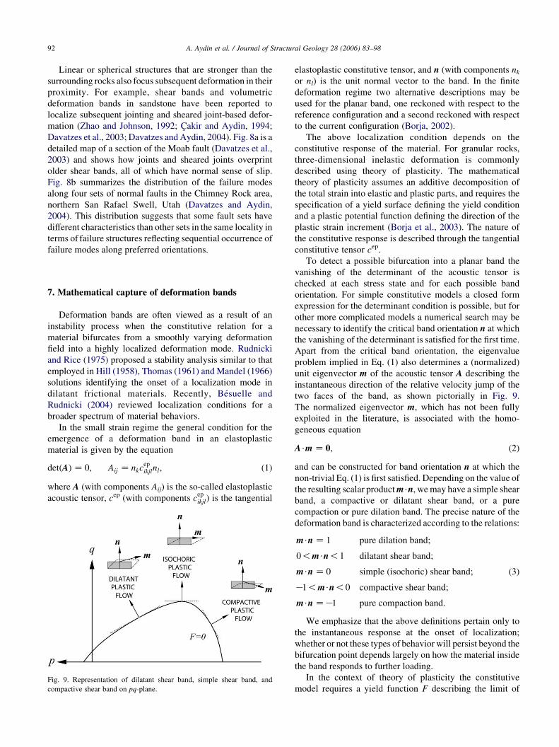
The micromechanics of failure depend on interplay among
grain boundary sliding, pore enlargement or collapse,
pressure solution, and grain fracturing, some of which are
schematically illustrated in Fig. 13. These mechanisms are
controlled by the petrophysical properties of the granular
rock and the loading conditions (Vesic and Clough, 1968;
Wood, 1990; Mavko et al., 1997).
Among the failure structures considered in this study
compaction and dilation bands appear to be most intriguing.
More specifically, localization of strain into narrow bands
by the growth of pores within the band is in striking contrast
to the ‘elastic crack’ concept based on propagation of
individual flaws producing macroscopic planar structures.
Also, we described planar shear failure structures formed
along pre-existing weak planes in granular rock. In spite of
some reports of classic shear fractures/faults in natural
environments (Vermilye and Scholz, 1999), there is no
unambiguous evidence that shear fractures composed of two
planar surfaces initiate, propagate, and develop in pristine
granular geomaterials. In this respect, the only structure that
is similar in form and concept to the idealized shear fracture/
fault is a slip surface (Aydin and Johnson, 1978). This
structure, however, has never been observed by itself in an
otherwise pristine granular rock (without a zone of shear
bands). The appearance of a slip surface always marks the
culmination of fault evolution in granular rocks in terms
of the fundamental structural components of a fault zone
(Aydin and Johnson, 1978; Shipton and Cowie, 2001). Thus,
Fig. 13. Schematic illustration of structures resulting from various failure modes in granular rock. Compaction, shearing, and dilation in narrow tabular bands
(top row) and sharp discontinuities (bottom row).
A. Aydin et al. / Journal of Structural Geology 28 (2006) 83–9896
the formation of a slip surface differs significantly from that
of an idealized shear fracture in terms of its initiation and
growth history.
Shear fractures/faults initiated from planar weaknesses
differ from idealized shear fractures by their out-of-plane
propagation which is crucial for the final geometry and
pattern of the system. Faults also develop by overprinting
structures (deformation bands, jointing, and subsequent
shearing). From the field geology point of view, recognizing
and deciphering complex fault zones involving localized
tabular deformation structures overprinted by sheared
planar failure structures (slip surfaces/sheared joints and
solution surfaces) pose challenging future research subjects.
We have also presented a mathematical framework for
characterizing the occurrence of tabular bands in geologic
materials using classical bifurcation theory and the math-
ematical theory of plasticity. The formulation is complete in
the sense that the end result specifies the type of deformation
band expected to form at localization. The characters of the
deformation band predicted by the theory depend on the
constitutive model, and thus to capture the constitutive
response of granular materials more accurately we have
presented a class of three-invariant elastoplastic constitutive
models. With the aforementioned bifurcation theory, this
class of constitutive models provides a mathematical
description of the formation of the three extreme failure
modes, namely, simple shear, pure compaction, and pure
dilation, as well as the combination modes described in the
geologic framework. We briefly described a criterion for
strong discontinuity and contrasted it with that for
deformation bands in that the former recognizes a vanishing
band thickness whereas the latter does not.
Acknowledgements
A. Aydin acknowledges financial support through the
National Science Foundation grant EAR-02-29862. Partial
support was also provided by US Department of Energy
grant DE-FG03-94ER14462. R.I. Borja acknowledges
support of National Science Foundation grant CMS-02-
01317, and US Department of Energy grant DE-FG02-
03ER15454. We thank Jennifer Wilson and an anonymous
reviewer, David Ferrill, the Editor, for their thoughtful
comments.
References
Al-Shaieb, Z., Puckette, J.O., Abdalla, A.A., Tigert, V., Ortoleva, P.J.,
1994. The banded character of pressure seals. In: Ortoleva, P.J. (Ed.),
Basin Compartments and Seals. AAPG Memoir 61, pp. 351–367.
Antonellini, M.A., Aydin, A., 1994. Effect of faulting on fluid flow in
porous sandstones: petrophysical properties. AAPG Bulletin 78,
355–377.
Antonellini, M.A., Aydin, A., Pollard, D.D., 1994a. Microstructure of
deformation bands in porous sandstones at Arches National Park, Utah.
Journal of Structural Geology 16, 941–959.
Antonellini, M.A., Aydin, A., Pollard, D.D., D’Onfro, D., 1994b.
Petrophysical study of faults in sandstones using petrographic image
analysis and X-ray computerized tomography. Pure and Applied
Geophysics 143, 181–201.
Argon, A.S., 1975. Plastic deformation of glassy polymers. In: Baer, E.,
Radcliffe, S.V. (Eds.), Polymeric Materials (Relationship Between
Structure and Mechanical Behaviour). ASM Monograph. Metals Park,
Ohio, pp. 412–486.
Aydin, A., 1978. Small faults formed as deformation bands in sandstone.
Pure and Applied Geophysics 116, 913–930.

A. Aydin et al. / Journal of Structural Geology 28 (2006) 83–98 97
Aydin, A., Johnson, A.M., 1978. Development of faults as zones of
deformation bands and as slip surfaces in sandstone. Pure and Applied
Geophysics 116, 931–942.
Aydin, A., Johnson, A.M., 1983. Analysis of faulting in porous sandstones.
Journal of Structural Geology 5, 19–31.
Berg, C.A., 1970. Plastic dilation and void interaction. In: Kanninen, M.F.,
Adler, W.F., Rosenfield, A.R., Jaffee, R.I. (Eds.), Inelastic Behavior of
Solids. McGraw-Hill, New York, pp. 171–210.
Berg, C.A., 1972. Ductile fracture by development of surfaces of unstable
cavity expansion. Journal of Research of the National Bureau of
Standards, Civil Engineering and Instrumentation 76C, 1–2.
Bernabe, Y., Bryer, D.T., Hayes, J.A., 1992. The effect of cement on
the strength of granular rocks. Geophysical Research Letters 19,
1511–1514.
Besuelle, P., 2001. Compacting and dilating shear bands in porous rock:
theoretical and experimental conditions. Journal of Geophysical
Research 106, 13435–13442.
Besuelle, P., Rudnicki, J.W., 2004. Localization: shear bands and
compaction bands. In: Gueguen, Y., Bouteca, M. (Eds.), Mechanics
of Fluid Saturated Rocks. International Geophysics Series 89. Elsevier
Academic Press, New York, pp. 219–321.
Bjørlykke, K., Høeg, K., 1997. Effects of burial diagenesis on stresses,
compaction and fluid flow in sedimentary basins. Marine and Petroleum
Geology 14, 267–276.
Borg, I.Y., Friedman, M., Handin, J.W., Higgs, D.V., 1960. Experimental
deformation of Saint Peter sand—a study of cataclastic flow. In:
Griggs, D.T., Handin, J.W. (Eds.), Rock Deformation—A Symposium.
Geological Society of America Memoir 79, pp. 133–191.
Borja, R.I., 2002. Bifurcation of elastoplastic solids to shear band mode at
finite strain. Computer Methods in Applied Mechanics and Engineering
191, 5287–5314.
Borja, R.I., 2003. Algorithm for a class of three-invariant elastoplastic
constitutive modes suitable for the analysis of deformation bands in
geomaterials. In: Onate, E., Owen, D.R.J. (Eds.), VII International
Conference on Computational Plasticity (COMPLAS 2003), CIMNE,
Barcelona, on CD-ROM.
Borja, R.I., 2004. Computational modeling of deformation bands in
granular media, II: Numerical simulations. Computer Methods in
Applied Mechanics and Engineering 193, 2699–2718.
Borja, R.I., Aydin, A., 2004. Computational modeling of deformation
bonds in granular media. I: Geological and mathematical framework.
Computer Methods in Applied Mechanics and Engineering 193,
2667–2698.
Borja, R.I., Regueiro, R.A., Lai, T.Y., 2000. FE modeling of strain
localization in soft rock. Journal of Geotechnical and Geoenviron-
mental Engineering 126, 335–343.
Borja, R.I., Sama, K.M., Sanz, P.F., 2003. On the numerical integration of
three-invariant elastoplastic constitutive models. Computer Methods in
Applied Mechanics and Engineering 192, 1227–1258.
Borradaile, G.J., 1981. Particulate flow of rock and the formation of
cleavage. Tectonophysics 72, 305–321.
Brace, W.F., Bombolakis, E.G., 1963. A note on brittle crack growth in
compression. Journal of Geophysical Research 68, 3709–3713.
Cakir, M., Aydin, A., 1994. Tectonics and Fracture Characteristics of the
Northern Lake Mead, SE Nevada, Proceedings of the Stanford Rock
Fracture Project Field Workshop. Stanford University, Stanford.
Cashman, S., Cashman, K., 2000. Cataclasis and deformation-band
formation in unconsolidated marine terrace sand, Humboldt County,
California. Geology 28, 111–114.
Cooke, M., Mollema, P., Pollard, D.D., Aydin, A., 2000. Interlayer slip and
joint localization in the East Kaibab Monocline, Utah: field evidence
and results from numerical modeling. In: Cosgrove, J.W., Ameen, M.S.
(Eds.), Forced Folds and Fractures. Geological Society, London,
Special Publication vol. 169, pp. 23–49.
Cotterell, B., Rice, J.R., 1980. Slightly curved or kinked cracks.
International Journal of Fracture 16, 155–169.
Cruikshank, K.M., Aydin, A., 1994. Role of fracture localization in arch
formation, Arches National Park, Utah. Geological Society of America
Bulletin 106, 879–891.
Cruikshank, K.M., Zhao, G., Johnson, A.M., 1991. Analysis of minor
fractures associated with joints and faulted joints. Journal of Structural
Geology 13, 865–886.
Curran, J.H., Carroll, M.M., 1979. Shear enhancement of void compaction.
Journal of Geophysical Research 84, 1105–1112.
Davatzes, N.C., Aydin, A., 2003. Overprinting faulting mechanisms in
sandstone. Journal of Structural Geology 25, 1795–1813.
Davatzes, N.C., Aydin, A., 2004. Overprinting faulting mechanisms in high
porosity sandstones of SE Utah. Journal of Structural Geology 25,
1795–1813.
Davatzes, N.C., Aydin, A., Eichhubl, P., 2003. Overprinting faulting
mechanisms during the development of multiple fault sets in sandstone,
Chimney Rock fault array, Utah, USA. Tectonophysics 363, 1–18.
Davis, G.H., 1999. Structural geology of the Colorado Plateau region of
southern Utah. Geological Society of America Special Paper, 342.
DiGiovanni, A.A., Fredrich, J.T., Holcomb, D.J., Olsson, W.A., in press.
Microscale damage evolution in compacting sandstone. In: Couples,
G.D., Lewis, H., Meredith, P. (Eds.), Relationships Between Fracture
Damage and Localisation. Geological Society, London, Special
Publications.
Drucker, D.C., Prager, W., 1952. Soil mechanics and plastic analysis or
limit design. Quarterly Applied Mathematics 10, 157–165.
Du Bernard, X., Eichhubl, P., Aydin, A., 2002. Dilation bands, a new form
of localized failure in granular media. Geophysical Research Letters 29
(24), 2176 doi: 1029/2002GLO15966.
Dunn, D.E., Lafountain, L.J., Jackson, R.E., 1973. Porosity dependence and
mechanism of brittle faulting in sandstone. Journal of Geophysical
Research 78, 2303–2317.
Dvorkin, J., Nur, A., 1996. Elasticity of high-porosity sandstones: theory
for two North Sea data sets. Geophysics 61, 1363–1370.
Engelder, T., 1974. Cataclasis and the generation of fault gouge. Geological
Society of America Bulletin 85, 1515–1522.
Engelder, T., 1987. Joints and shear fractures in rock. In: Atkinson, B.K.
(Ed.), Fracture Mechanics of Rock. Academic Press, London,
pp. 27–69.
Fletcher, R.C., Pollard, D.D., 1981. Anticrack model for pressure solution
surfaces. Geology 9, 419–424.
Fossen, H., Hesthammer, J., 1997. Geometric analysis and scaling relations
of deformation bands in porous sandstone. Journal of Structural
Geology 19, 1479–1493.
Friedman, M., Logan, J.M., 1973. Luders’ bands in experimentally
deformed sandstone and limestone. Geological Society of America
Bulletin 84, 1465–1476.
Gallagher, J.J., 1987. Fractography of sand grains broken by uniaxial
compression. In: Marshall, J.R. (Ed.), Classic Particles. Van Nostrand
Reinhold, New York, pp. 189–228.
Groshong Jr., R.H., 1988. Low-temperature deformation mechanisms
and their interpretation. Geological Society of America Bulletin 100,
1329–1360.
Haimson, B.C., 2001. Fracture-like borehole breakouts in high-porosity
sandstone: are they caused by compaction bands? Physics and
Chemistry of the Earth 26, 15–20.
Hill, R., 1958. A general theory of uniqueness and stability in elastic–
plastic solids. Journal of the Mechanics and Physics of Solids 6,
236–249.
Hill, R.E., 1989. Analysis of deformation bands in the Aztec Sandstone,
Valley of Fire, Nevada. MS Thesis, Geosciences Department,
University of Nevada, Las Vegas.
Hubbert, M.K., Rubey, W.W., 1959. Mechanics of fluid-filled porous solids
and its application to overthrust faulting, [Part] 1 of role of fluid
pressure in mechanics of overthrust faulting. Geological Society of
America Bulletin 70, 115–166.
Issen, K.A., Rudnicki, J.W., 2000. Conditions for compaction bands in
porous rock. Journal of Geophysical Research 105, 21529–21536.

A. Aydin et al. / Journal of Structural Geology 28 (2006) 83–9898
Jaeger, J.C., Cook, N.G.W., 1979. Fundamentals of Rock Mechanics, 3rd
ed. Chapman & Hall, New York.
Lade, P.V., Duncan, J.M., 1975. Elastoplastic stress-strain theory for
cohesionless soil. Journal of Geotechnical Engineering Division, ASCE
101, 1037–1053.
Mair, K., Main, I., Elphick, S., 2000. Sequential growth of deformation
bands in the laboratory. Journal of Structural Geology 22, 25–42.
Mandel, J., 1966. Conditions de stabilite et postulat de Drucker,
Proceedings IUTAM Symposium on Rheology and Soil Mechanics.
Springer, Berlin pp. 58–68.
Matsuoka, H., Nakai, T., 1974. Stress-deformation and strength character-
istics of soil under three different principal stresses. Proceedings of the
Japanese Society of Civil Engineers 232, 59–70.
Mavko, G., Mukerji, T., Dvorkin, J., 1997. The Rock Physics Handbook.
Tools for Seismic Analysis of Porous Media. Cambridge University
Press, Cambridge.
Menendez, B., Zhu, W., Wong, T.-F., 1996. Micromechanics of brittle
faulting and cataclastic flow in Berea sandstone. Journal of Structural
Geology 18, 1–16.
Mollema, P.N., Antonellini, M.A., 1996. Compaction bands: a structural
analog for anti-mode I cracks in aeolian sandstone. Tectonophysics 267,
209–228.
Myers, R.D., 1999. Structure and hydraulic properties of brittle faults in
sandstone. PhD Thesis, Stanford University, Stanford.
Myers, R.D., Aydin, A., 2004. The evolution of faults formed by shearing
across joint zones in sandstone. Journal of Structural Geology 26, 947–
966.
Olsson, W.A., 1999. Theoretical and experimental investigation of
compaction bands in porous rock. Journal of Geophysical Research
104, 7219–7228.
Olsson, W.A., 2000. Origin of Luders’ bands in deformed rock. Journal of
Geophysical Research 105, 5931–5938.
Pittman, E.D., 1981. Effect of fault-related granulation on porosity and
permeability of quartz sandstones, Simpson Group (Ordovician),
Oklahoma. American Association of Petroleum Geologists Bulletin
65, 2381–2387.
Pollard, D.D., Aydin, A., 1988. Progress in understanding jointing over the
past one hundred years. Geological Society of America Bulletin 100,
1181–1204.
Pollard, D.D., Segall, P., 1987. Theoretical displacements and stresses near
fractures in rock: with applications to faults, joints, veins, dikes, and
solution surfaces. In: Atkinson, B.K. (Ed.), Fracture Mechanics of
Rock. Academic Press, London, pp. 277–349.
Rawling, G.C., Goodwin, L.B., 2003. Cataclastic and particulate flow in
faulted, poorly lithified sediments. Journal of Structural Geology 25,
317–331.
Renard, F., Brosse, E., Gratier, J.P., 2000. The different processes involved
in the mechanism of pressure solution in quartz-rich rocks and their
interactions. In: Worden, R.H., Morad, S. (Eds.), Quartz Cementation in
Sandstones Special Publication Number 29 of the International
Association of Sedimentologists. Blackwell, London, pp. 67–78.
Rudnicki, J.W., 2002. Conditions for compaction and shear bands in a
transversely isotropic material. International Journal of Solids and
Structures 39, 3741–3756.
Rudnicki, J.W., Olsson, W.A., Rice, J.R., 1975. Conditions for the
localization of deformation in pressure-sensitive dilatant materials.
Journal of the Mechanics and Physics of Solids 23, 371–394.
Segall, P., Pollard, D.D., 1983. Nucleation and growth of strike-slip faults
in granite. Journal of Geophysical Research 88, 555–568.
Shah, K.R., Wong, T.-F., 1997. Fracturing at contact surfaces subject to
normal and tangential loads. International Journal of Rock Mechanics
and Mining Sciences 34, 727–739.
Shipton, Z.K., Cowie, P.A., 2001. Damage zone and slip-surface evolution
over mm to km scales in high-porosity Navajo sandstone, Utah. Journal
of Structural Geology 23, 1825–1844.
Sternlof, K., Pollard, D.D., 2001. Deformation bands as linear elastic
fractures: progress in theory and observation. Eos Transactions
American Geophysical Union 82 (47), F1222.
Sternlof, K., Pollard, D., 2002. Numerical modelling of compactive
deformation bands as granular anti-cracks. Eos Transactions American
Geophysical Union 87 (47), F1347.
Thomas, T.Y., 1961. Plastic Flow and Fracture of Solids. Academic Press,
New York.
Vermilye, J.M., Scholz, C.H., 1999. Fault propagation and segmentation;
insight from the microstructural examination of a small fault. Journal of
Structural Geology 21, 1623–1636.
Vesic, A.S., Clough, G.W., 1968. Behaviour of granular materials
under high stresses. Journal of the Soil Mechanics and Foundation
Division Proceedings of the American Society of Civil Engineers 94,
661–688.
Wilson, J.E., Goodwin, L.B., Lewis, C.J., 2003. Deformation bands
in nonwelded ignimbrites: petrophysical controls on fault-zone
deformation and evidence of preferential fluid flow. Geology 31,
837–840.
Wong, T.-F., David, C., Zhu, W.L., 1997. The transition from brittle
faulting to cataclastic flow in porous sandstones: mechanical
deformation. Journal of Geophysical Research 102, 3009–3025.
Wong, T.-F., Baud, P., Klein, E., 2001. Localized failure modes in a
compactant porous rock. Geophysical Research Letters 28, 2521–2524.
Wong, T.-F., David, C., Menendez, B., 2004. Mechanical compaction. In:
Gueguen, Y., Bouteca, M. (Eds.), Mechanics of Fluid Saturated Rocks.
International Geophysics Series 89. Elsevier Academic Press, New
York, pp. 55–114.
Wood, D.M., 1990. Soil Behavior and Critical State Soil Mechanics.
Cambridge University Press, Cambridge.
Zhang, J., Wong, T-F., Davis, D.M., 1990. Micromechanics of pressure-
induced grain crushing in porous rocks. Journal of Geophysical
Research 95, 341–352.
Zhao, G., Johnson, A.M., 1992. Sequence of deformation recorded in joints
and faults, Arches National Park, Utah. Journal of Structural Geology
14, 225–236.