Embed Size (px)
Citation preview
All rights reserved © The Geological Association of Canada, 2004 This document is protected by copyright law. Use of the services of Érudit(including reproduction) is subject to its terms and conditions, which can beviewed online.https://apropos.erudit.org/en/users/policy-on-use/
This article is disseminated and preserved by Érudit.Érudit is a non-profit inter-university consortium of the Université de Montréal,Université Laval, and the Université du Québec à Montréal. Its mission is topromote and disseminate research.https://www.erudit.org/en/
Document generated on 01/15/2022 10:33 a.m.
Geoscience Canada
Geological, Ocean, and Mineral CO2 Sequestration Options: ATechnical ReviewDanae A. Voormeij and George J. Simandl
Volume 31, Number 1, March 2004
URI: https://id.erudit.org/iderudit/geocan31_1art02
See table of contents
Publisher(s)The Geological Association of Canada
ISSN0315-0941 (print)1911-4850 (digital)
Explore this journal
Cite this articleVoormeij, D. A. & Simandl, G. J. (2004). Geological, Ocean, and Mineral CO2Sequestration Options: A Technical Review. Geoscience Canada, 31(1), 11–22.
Article abstractOf the six greenhouse gases (GHG) covered by the Kyoto protocol, carbondioxide (CO2) is the greatest contributor to Canada's total GHG emissions. Fossilfuel combustion is the main source of anthropogenic CO2, and it currentlysupplies over 85% of the global energy demand. Worldwide, an effort forreduction of CO2 emissions aims at increased efficiency of fossil energy usage,development of energy sources with lower carbon content and increasedreliability on alternative energy sources such as wind, solar, geothermal andnuclear. However, to meet the objectives of the Kyoto agreement, CO2sequestration methods may be needed. In this review, the methods that we willcover are storage in oil and gas reservoirs, in deep coal seams, in deep salineaquifers, in deep ocean, in salt caverns, and mineral carbonation. Each of thesemethods has its weaknesses and strengths.
GEOSCIENCE CANADA Volume 31 Number 1 March 2004 11
ARTICLE
DDDDDanae A. anae A. anae A. anae A. anae A. VVVVVoormeijoormeijoormeijoormeijoormeij11111 and G and G and G and G and George J.eorge J.eorge J.eorge J.eorge J.Simandl,Simandl,Simandl,Simandl,Simandl,22222
1University of Victoria, School of Earthand Ocean Sciences, P.O. Box 3055,STN CSC, Victoria, BC, Canada,V8W 3P6, [email protected] Columbia Ministry of Energy andMines and adjunct professor at Universityof Victoria, PO Box 9333 Stn. Prov.Govt., Victoria, BC, V8W 9N3,[email protected]
SUMMARYOf the six greenhouse gases (GHG)covered by the Kyoto protocol, carbondioxide (CO2) is the greatest contributorto Canada’s total GHG emissions. Fossilfuel combustion is the main source ofanthropogenic CO2, and it currentlysupplies over 85% of the global energydemand. Worldwide, an effort forreduction of CO2 emissions aims atincreased efficiency of fossil energyusage, development of energy sourceswith lower carbon content and increasedreliability on alternative energy sourcessuch as wind, solar, geothermal and
nuclear. However, to meet the objectivesof the Kyoto agreement, CO2sequestration methods may be needed.In this review, the methods that we willcover are storage in oil and gasreservoirs, in deep coal seams, in deepsaline aquifers, in deep ocean, in saltcaverns, and mineral carbonation. Eachof these methods has its weaknesses andstrengths.
RÉSUMÉDes six types de gaz à effet de serre(GES) dont il est question dans le traitéde Kyoto, le gaz carbonique (CO2) estcelui qui contribue le plus au émissionstotales de GES au Canada. Lacombustion de carburants fossiles quirépond présentement à 85 % desbesoins d’énergie de notre monde,constitue la principal source de CO2anthropogénique. L’effort mondial deréduction des émissions de CO2 vise àaugmenter l’efficacité de l’utilisation desénergies fossiles, à développer dessources d’énergie contenant moins decarbone et à augmenter l’apport d’autressources d’énergie comme le vent, lesoleil, l’énergie géothermique et l’énergienucléaire. Cependant, pour atteindre lesobjectifs du traité de Kyoto, on devrapeut-être recourir à des méthodes deséquestration du CO2. Dans la présenteétude rétrospective, les méthodesconsidérées sont les suivantes : lestockage dans des réservoirs de pétroleet de gaz, dans des couches de charbonen profondeur, dans des aquifères salinsprofonds, dans le fond des océans, dansdes cavernes de gisements de sel, ainsique par carbonatation de minéraux.Chacune de ces méthodes présentent desavantages et des inconvénients.
INTRODUCTIONCanada’s Kyoto commitments are toreduce its annual greenhouse gas (GHG)
GEOLOGICAL, OCEAN,AND MINERAL CO2SEQUESTRATIONOPTIONS: A TECHNICALREVIEW
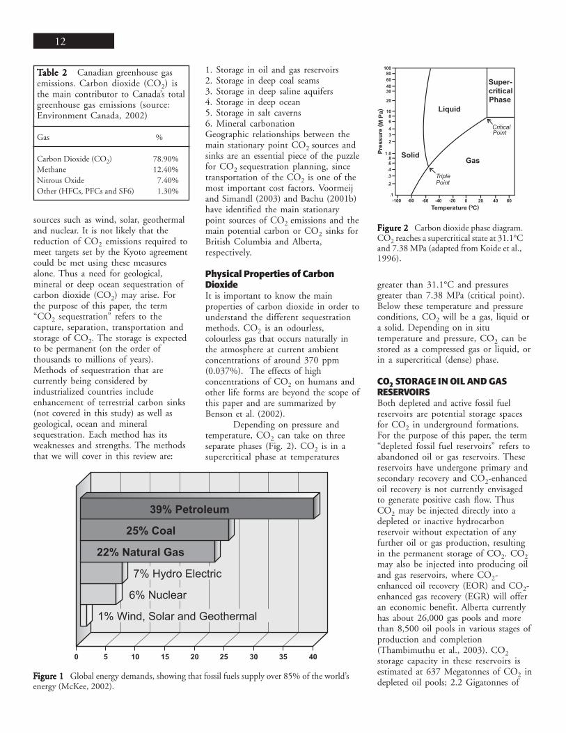
emissions levels by 6% relative to its1990 levels (Environment Canada,2002). Although Canada contributesonly about 3% of total global GHGemissions (Table 1), it is one of thehighest per capita emitters (23.6 tonneCO2 equivalent per year), largelybecause of its resource-based economy,cool climate (i.e., the need for heating)and travel distances (EnvironmentCanada 2002). Of the six GHGscovered by the Kyoto protocol, CO2 isthe greatest contributor to Canada’s totalGHG emissions (Table 2). Fossil fuelcombustion is the main source ofanthropogenic CO2, and it currentlysupplies over 85% of the world’s energydemand (Fig. 1). The main engineeringeffort for reduction of CO2 emissions isaimed at increased efficiency of fossilenergy usage, development of energysources with lower carbon content, andincreased reliance on alternative energy
CO2 emissions Mt %
World total (1999) 23900.00 100.00Canada total (1990) 601.00 2.51Canada total (2000) 726.00 3.04Alberta 223.00 0.93Ontario 207.00 0.87Quebec 90.40 0.38British Columbia 65.90 0.28Saskatchewan 61.80 0.26Nova Scotia 21.50 0.09Manitoba 21.40 0.09New Brunswick 20.20 0.08Newfoundland 8.80 0.04Prince Edward Island 2.10 0.01North West Territories 1.80 0.01Yukon 0.53 0.00
TTTTTable 1able 1able 1able 1able 1 Canada’s total CO2 emissions for2000 as compared to global emissionestimates. Numbers for emission levels arein Megatonnes (Mt) of CO2 equivalent(source: Environment Canada, 2002)
12
TTTTTable 2 able 2 able 2 able 2 able 2 Canadian greenhouse gasemissions. Carbon dioxide (CO2) isthe main contributor to Canada’s totalgreenhouse gas emissions (source:Environment Canada, 2002)
Gas %
Carbon Dioxide (CO2) 78.90%Methane 12.40%Nitrous Oxide 7.40%Other (HFCs, PFCs and SF6) 1.30%
sources such as wind, solar, geothermaland nuclear. It is not likely that thereduction of CO2 emissions required tomeet targets set by the Kyoto agreementcould be met using these measuresalone. Thus a need for geological,mineral or deep ocean sequestration ofcarbon dioxide (CO2) may arise. Forthe purpose of this paper, the term“CO2 sequestration” refers to thecapture, separation, transportation andstorage of CO2. The storage is expectedto be permanent (on the order ofthousands to millions of years).Methods of sequestration that arecurrently being considered byindustrialized countries includeenhancement of terrestrial carbon sinks(not covered in this study) as well asgeological, ocean and mineralsequestration. Each method has itsweaknesses and strengths. The methodsthat we will cover in this review are:
1. Storage in oil and gas reservoirs2. Storage in deep coal seams3. Storage in deep saline aquifers4. Storage in deep ocean5. Storage in salt caverns6. Mineral carbonationGeographic relationships between themain stationary point CO2 sources andsinks are an essential piece of the puzzlefor CO2 sequestration planning, sincetransportation of the CO2 is one of themost important cost factors. Voormeijand Simandl (2003) and Bachu (2001b)have identified the main stationarypoint sources of CO2 emissions and themain potential carbon or CO2 sinks forBritish Columbia and Alberta,respectively.
Physical Properties of CarbonDioxideIt is important to know the mainproperties of carbon dioxide in order tounderstand the different sequestrationmethods. CO2 is an odourless,colourless gas that occurs naturally inthe atmosphere at current ambientconcentrations of around 370 ppm(0.037%). The effects of highconcentrations of CO2 on humans andother life forms are beyond the scope ofthis paper and are summarized byBenson et al. (2002).
Depending on pressure andtemperature, CO2 can take on threeseparate phases (Fig. 2). CO2 is in asupercritical phase at temperatures
FFFFFigurigurigurigurigure 1e 1e 1e 1e 1 Global energy demands, showing that fossil fuels supply over 85% of the world’senergy (McKee, 2002).
greater than 31.1°C and pressuresgreater than 7.38 MPa (critical point).Below these temperature and pressureconditions, CO2 will be a gas, liquid ora solid. Depending on in situtemperature and pressure, CO2 can bestored as a compressed gas or liquid, orin a supercritical (dense) phase.
CO2 STORAGE IN OIL AND GASRESERVOIRSBoth depleted and active fossil fuelreservoirs are potential storage spacesfor CO2 in underground formations.For the purpose of this paper, the term“depleted fossil fuel reservoirs” refers toabandoned oil or gas reservoirs. Thesereservoirs have undergone primary andsecondary recovery and CO2-enhancedoil recovery is not currently envisagedto generate positive cash flow. ThusCO2 may be injected directly into adepleted or inactive hydrocarbonreservoir without expectation of anyfurther oil or gas production, resultingin the permanent storage of CO2. CO2may also be injected into producing oiland gas reservoirs, where CO2-enhanced oil recovery (EOR) and CO2-enhanced gas recovery (EGR) will offeran economic benefit. Alberta currentlyhas about 26,000 gas pools and morethan 8,500 oil pools in various stages ofproduction and completion(Thambimuthu et al., 2003). CO2storage capacity in these reservoirs isestimated at 637 Megatonnes of CO2 indepleted oil pools; 2.2 Gigatonnes of
Figure 2 Figure 2 Figure 2 Figure 2 Figure 2 Carbon dioxide phase diagram.CO2 reaches a supercritical state at 31.1°Cand 7.38 MPa (adapted from Koide et al.,1996).
GEOSCIENCE CANADA Volume 31 Number 1 March 2004 13
CO2 in gas caps of approximately 5,000oil reservoirs and 9.8 Gigatonnes ofCO2 storage capacity in gas reservoirsthat are not associated with oil pools(Thambimuthu et al., 2003). Of themore than 8,500 oil pools in Alberta,4,273 reservoirs were identified assuitable for CO2- EOR.
Typically, oil reservoirs haveundergone a variety of production andinjection processes during primary andsecondary recovery (e.g. gas, water orsteam injection), as described byJimenez and Chalaturnyk (2003). As atertiary recovery process, CO2 can beinjected into the reservoir to improvethe mobility of the remaining oil,thereby extending the production life ofthe reservoir. Injection of CO2 intoproducing gas reservoirs for EGR waspreviously believed to riskcontaminating the natural gas reserve(Stevens et al., 2000). However, recentstudies by Oldenburg et al. (2001) andOldenburg and Benson (2002) suggestthat mixing of the CO2 and methane(CH4) in a gas reservoir would belimited because of the high density andviscosity of CO2 relative to the naturalgas. Furthermore, significant quantitiesof natural gas can be produced by re-pressurization of the reservoir. It ispossible that improved gas recoverycould more than offset the cost of CO2capture and injection (Davison et al.,2001).
Depleted Oil and Gas ReservoirsFollowing more than a century ofintensive petroleum exploitation,thousands of oil and gas fields areapproaching the ends of theireconomically productive lives (Davisonet al., 2001). Some of these exhaustedfields are potential sites for CO2sequestration. The concept of CO2disposal in depleted oil and gasreservoirs is that the hydrogeologicalconditions that allowed thehydrocarbons to accumulate in the firstplace will also permit the accumulationand trapping of CO2 in the spacevacated by the produced hydrocarbons(Hitchon et al., 1999; Gentzis, 2000).The caprock that prevented the escapeof oil and gas over geological timeshould retain the sequestered CO2 forthousands of years (Bachu, 2001a), as
long as it is not damaged as a result ofoverpressure during the CO2 injection(van der Meer, 1993), or by thepresence of unsealed, improperlycompleted or abandoned wells (Hitchonet al., 1999). Depleted hydrocarbonreservoirs that are filled with connatewater (fully water-saturated reservoirs)offer limited storage capacity. Storage ofCO2 in water-saturated reservoirswould, in practice, amount to aquiferstorage (Bachu, 2000; van der Meer,2003).
Closed, underpressured,depleted gas reservoirs are excellentgeological traps for CO2 storage. Firstly,primary recovery of gas fields usuallyremoves as much as 95% of the originalgas in place (Bachu, 2001a), creatinglarge storage potential. Secondly, theinjected CO2 can be used to restore thereservoir to its original pressure (Bachuet al., 2000), thereby preventingpossible collapse or man-inducedsubsidence. Thirdly, the trappingmechanism that retained hydrocarbonsin the first place should ensure thatCO2 does not reach the surface. Andlastly, the existing surface and down-hole infrastructure used for productionof gas may be modified fortransportation and injection ofsupercritical CO2. About 80% of theworld’s hydrocarbon fields are at depthsgreater than 800 m (IEA, website), thusmeeting the pressure and temperaturerequirements needed to store CO2 as asupercritical fluid (van der Meer, 1993).Spatial association betweenhydrocarbon production and thepresence of reservoirs suitable for CO2sequestration may result in sharedinfrastructure and reduction oftransportation costs. Furthermore,depleted hydrocarbon fields commonlyhave an established geological databaseand as such, reservoir characteristicsare well known. Currently, thepetroleum industry is reluctant toconsider storage of CO2 in depletedhydrocarbon reservoirs, becauseabandoned fields will still contain oiland gas resources (U.S. Dept of Energy,2002), which potentially have economicvalue if oil prices were to rise enough ornew EOR technologies were developedin the future (Davison et al., 2001;Bachu et al., 2000).
Acid gas injection operations inthe Western Canada Sedimentary Basinare a useful small-scale analogue forstorage of CO2 into depleted oil or gasreservoirs. Acid gas is a product of oiland gas processing and consists of acombination of CO2 and hydrogensulphide (H2S). It is either injected intodepleted hydrocarbon reservoirs or intosaline aquifers for the purpose ofreducing atmospheric H2S emissions.The technology used in acid gasinjection in terms of transportation,injection and storage may becomparable to that of geologicalsequestration of CO2 (Bachu andGunter, 2003).
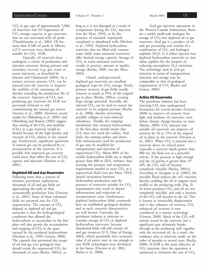
Active Oil ReservoirsThe petroleum industry has beeninjecting CO2 into undergroundformations for several decades (Gentzis,2000) to improve oil recovery fromlight and medium oil reservoirs, evenbefore climate change became an issue(Bachu, 2000). CO2 injected intosuitable oil reservoirs can improve oilrecovery by 10 to 15% of the originaloil in place in the reservoir (Davison etal., 2001). When CO2 is injected into areservoir above its critical point(typically a reservoir depth greater than800 m), the fluid acts as a powerfulsolvent. If the pressure is high enoughand the oil gravity is greater than 25°API, the CO2 and oil becomecompletely miscible (Bachu, 2001a).According to Aycaguer et al. (2001), themiscible flood reduces the oil’s viscosity,thereby enabling the oil to migrate morereadily to the producing wells (Fig. 3).At lower pressures CO2 and oil are notcompletely miscible, and only a fractionof the CO2 will dissolve in the oil. Thisis known as immiscible displacementand it also enhances oil recovery. CO2enhanced oil recovery is nowconsidered as a mature technology(Gentzis, 2000). Much of the CO2 willremain stored in the reservoir, but asignificant part ultimately breaksthrough at the producing well, togetherwith the recovered oil. As a result, theresidence time is relatively small, on theorder of months to several years (Bachu,2000). If EOR is the main objective ofCO2 injection, then the operation isoptimized to minimize the cost of CO2
14
used and maximize the oil recovery. Anexample of this is Pan West Petroleum’sJoffre Viking EOR field in Alberta.However, CO2 sequestration differsfrom CO2-EOR: its main objective is tosequester as much CO2 in the reservoiras possible and to keep it undergroundthousands if not millions years (van derMeer, 2003; Benson, 2000).
A life cycle assessment study onEOR with injection of CO2 in thePermian Basin of West Texas (Aycagueret al., 2001) suggested that the amountof CO2 injected, not including recycledCO2, may balance the amount of CO2in emissions that ultimately areproduced by combustion of theextracted hydrocarbon product. Most ofthe existing CO2-EOR projects in theworld use naturally occurring sources.CO2 from natural carbon dioxidereservoirs, where the infrastructure fordistribution is already present, providedelivery without major capital costs(Aycaguer et al., 2001) and withoutprocessing (Smith, 1998). To helpmitigate the release of CO2 to theatmosphere, the source of CO2 forEOR should come from anthropogenic(man-made) sources. A Canadian studydone by Tontiwachwuthikul et al. (1998)on the economics of CO2 productionfrom coal-fired power plants concludedthat flue gas extraction could be an
Figure 3Figure 3Figure 3Figure 3Figure 3 Simplified diagram showing a CO2-enhanced oil recovery (EOR) operation(modified from IEA R&D Programme, 2001).
economically viable CO2 supply sourcefor CO2-EOR projects in WesternCanada, should oil prices increasesubstantially.
Canada is the forerunner in thetechnology of using anthropogenic CO2emissions in a large-scale EOR projectat the Weyburn oil field inSaskatchewan. The ongoing projectaims at implementing a guideline forgeological storage of anthropogenicCO2 by EOR (Moberg, 2001;Whittaker and Rostron, 2003).Although natural sources can supplyCO2 at a lower cost (Bachu, 2000),funding provided for research makes itfeasible to use anthropogenic sources.CO2 is captured from the Great Plainscoal-gasification plant at Beulah, NorthDakota, USA and transported through a320 km pipeline to the Weyburn Pool.The injected CO2 is 95% pure andinitial injection rates are 5000 tons/day(Moberg et al., 2003). The reservoir islocated within the Williston Basin andhas temperatures near 65°C andpressures around 14.5 Mpa, whichindicate that the injected CO2 will likelyexist as a supercritical fluid (Whittakerand Rostron, 2003). The CO2 from theproduced oil will be captured and re-injected into the reservoir so that mostof the anthropogenic CO2 used forEOR will ultimately be sequestered
(Whittaker and Rostron, 2003). Anestimated 20 Megatonnes of CO2 willbe injected over the project life(Moberg et al., 2003). Potential futuresources of CO2 include the purified fluegas from Saskatchewan coal-firedthermal plants, such as those atBoundary Dam, Poplar River and Shank(Huang, 2001).
CO2 STORAGE IN COAL SEAMSCoal beds are a potential storagemedium for CO2. Canada has abundantcoal resources; some of them lie atdepths too great to be considered forconventional mining. CO2 can beinjected into suitable coal seams whereit will be adsorbed onto the coal andstored in the pore matrix of the coalseams for geological time. Since fluegas, a mixture of CO2 and nitrogen(N2) accounts for 80% of CO2emissions in western Canada (Reeve,2000), an alternative to CO2-onlystorage is injection of flue gas into coalbeds, which may avoid the high cost ofCO2 separation (Law et al., 2003).
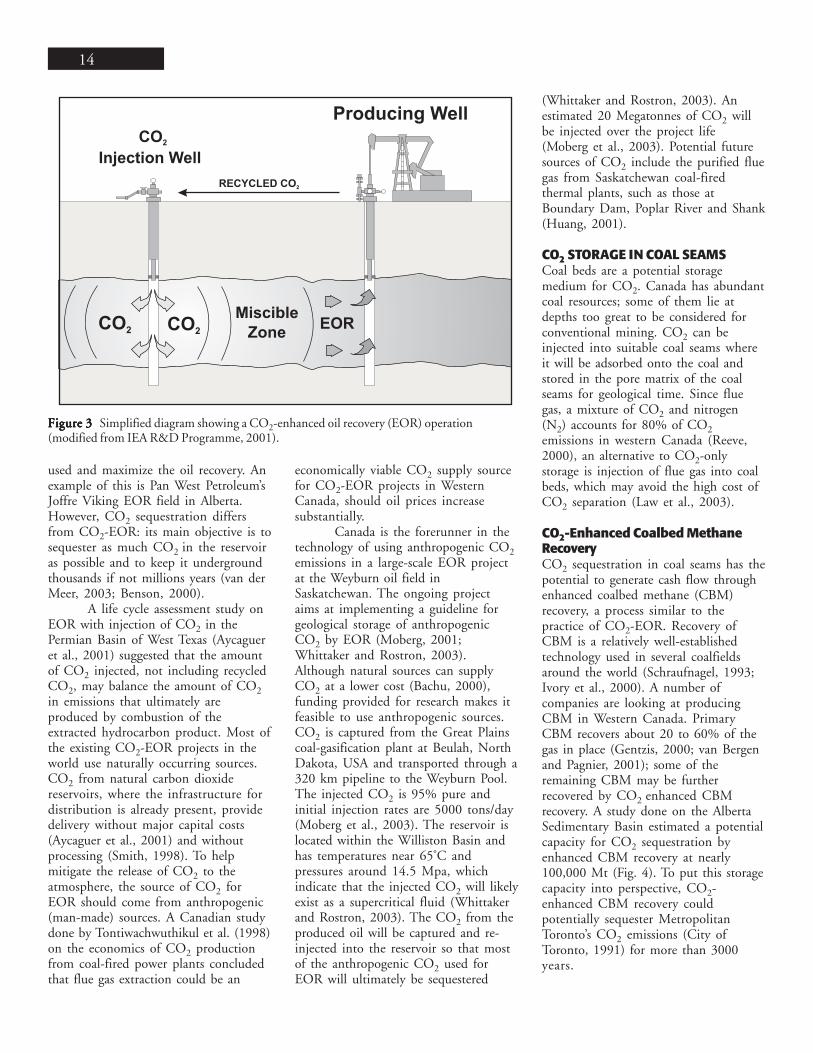
CO2-Enhanced Coalbed MethaneRecoveryCO2 sequestration in coal seams has thepotential to generate cash flow throughenhanced coalbed methane (CBM)recovery, a process similar to thepractice of CO2-EOR. Recovery ofCBM is a relatively well-establishedtechnology used in several coalfieldsaround the world (Schraufnagel, 1993;Ivory et al., 2000). A number ofcompanies are looking at producingCBM in Western Canada. PrimaryCBM recovers about 20 to 60% of thegas in place (Gentzis, 2000; van Bergenand Pagnier, 2001); some of theremaining CBM may be furtherrecovered by CO2 enhanced CBMrecovery. A study done on the AlbertaSedimentary Basin estimated a potentialcapacity for CO2 sequestration byenhanced CBM recovery at nearly100,000 Mt (Fig. 4). To put this storagecapacity into perspective, CO2-enhanced CBM recovery couldpotentially sequester MetropolitanToronto’s CO2 emissions (City ofToronto, 1991) for more than 3000years.
GEOSCIENCE CANADA Volume 31 Number 1 March 2004 15
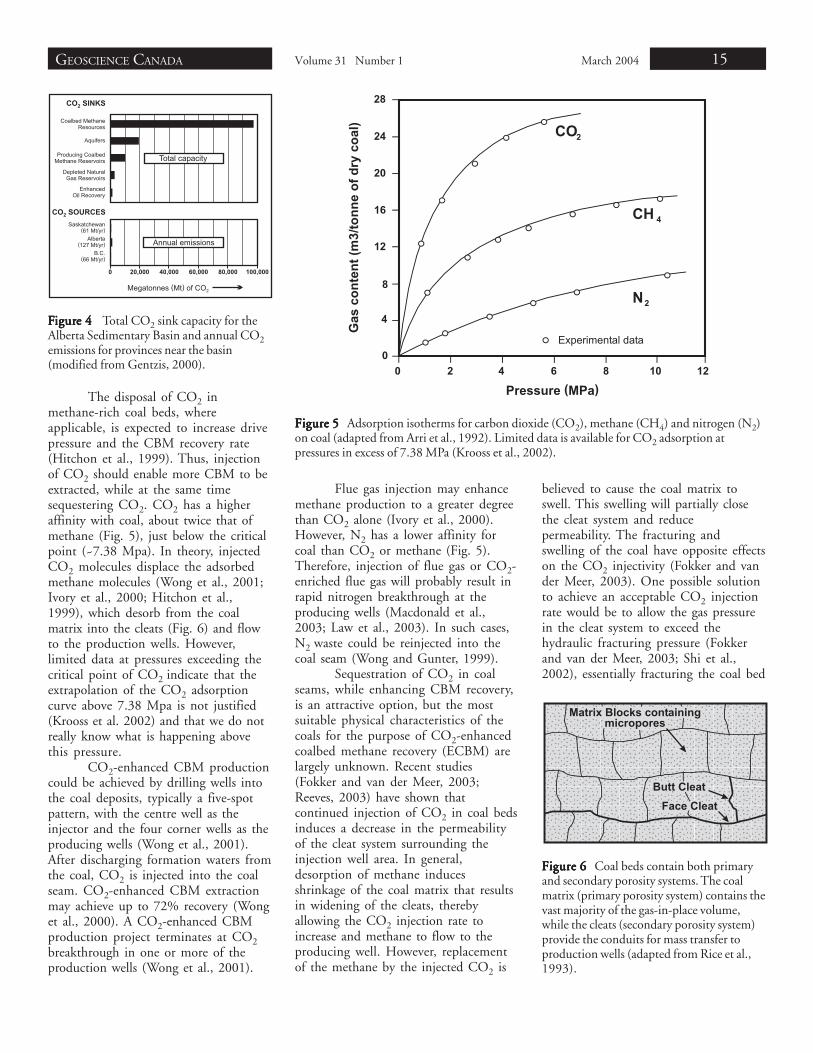
The disposal of CO2 inmethane-rich coal beds, whereapplicable, is expected to increase drivepressure and the CBM recovery rate(Hitchon et al., 1999). Thus, injectionof CO2 should enable more CBM to beextracted, while at the same timesequestering CO2. CO2 has a higheraffinity with coal, about twice that ofmethane (Fig. 5), just below the criticalpoint (~7.38 Mpa). In theory, injectedCO2 molecules displace the adsorbedmethane molecules (Wong et al., 2001;Ivory et al., 2000; Hitchon et al.,1999), which desorb from the coalmatrix into the cleats (Fig. 6) and flowto the production wells. However,limited data at pressures exceeding thecritical point of CO2 indicate that theextrapolation of the CO2 adsorptioncurve above 7.38 Mpa is not justified(Krooss et al. 2002) and that we do notreally know what is happening abovethis pressure.
CO2-enhanced CBM productioncould be achieved by drilling wells intothe coal deposits, typically a five-spotpattern, with the centre well as theinjector and the four corner wells as theproducing wells (Wong et al., 2001).After discharging formation waters fromthe coal, CO2 is injected into the coalseam. CO2-enhanced CBM extractionmay achieve up to 72% recovery (Wonget al., 2000). A CO2-enhanced CBMproduction project terminates at CO2breakthrough in one or more of theproduction wells (Wong et al., 2001).
FFFFFigurigurigurigurigure 4e 4e 4e 4e 4 Total CO2 sink capacity for theAlberta Sedimentary Basin and annual CO2emissions for provinces near the basin(modified from Gentzis, 2000).
Flue gas injection may enhancemethane production to a greater degreethan CO2 alone (Ivory et al., 2000).However, N2 has a lower affinity forcoal than CO2 or methane (Fig. 5).Therefore, injection of flue gas or CO2-enriched flue gas will probably result inrapid nitrogen breakthrough at theproducing wells (Macdonald et al.,2003; Law et al., 2003). In such cases,N2 waste could be reinjected into thecoal seam (Wong and Gunter, 1999).
Sequestration of CO2 in coalseams, while enhancing CBM recovery,is an attractive option, but the mostsuitable physical characteristics of thecoals for the purpose of CO2-enhancedcoalbed methane recovery (ECBM) arelargely unknown. Recent studies(Fokker and van der Meer, 2003;Reeves, 2003) have shown thatcontinued injection of CO2 in coal bedsinduces a decrease in the permeabilityof the cleat system surrounding theinjection well area. In general,desorption of methane inducesshrinkage of the coal matrix that resultsin widening of the cleats, therebyallowing the CO2 injection rate toincrease and methane to flow to theproducing well. However, replacementof the methane by the injected CO2 is
believed to cause the coal matrix toswell. This swelling will partially closethe cleat system and reducepermeability. The fracturing andswelling of the coal have opposite effectson the CO2 injectivity (Fokker and vander Meer, 2003). One possible solutionto achieve an acceptable CO2 injectionrate would be to allow the gas pressurein the cleat system to exceed thehydraulic fracturing pressure (Fokkerand van der Meer, 2003; Shi et al.,2002), essentially fracturing the coal bed
Figure 5 Figure 5 Figure 5 Figure 5 Figure 5 Adsorption isotherms for carbon dioxide (CO2), methane (CH4) and nitrogen (N2)on coal (adapted from Arri et al., 1992). Limited data is available for CO2 adsorption atpressures in excess of 7.38 MPa (Krooss et al., 2002).
Figure 6Figure 6Figure 6Figure 6Figure 6 Coal beds contain both primaryand secondary porosity systems. The coalmatrix (primary porosity system) contains thevast majority of the gas-in-place volume,while the cleats (secondary porosity system)provide the conduits for mass transfer toproduction wells (adapted from Rice et al.,1993).
16
in the vicinity of the injection well toenhance permeability. However, ifrepeated hydraulic fracturing isnecessary to maintain connectivitybetween the well bore and thepermeable areas of the coal seam, thismay result in over/under burdenfracturing (Gale, 2003), and subsequentCO2 leakage.
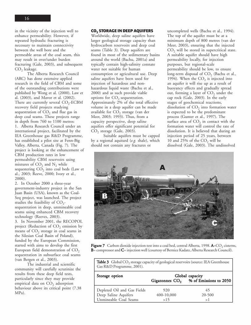
The Alberta Research Council(ARC) has done extensive appliedresearch in the field of CBM and someof the outstanding contributions werepublished by Wong et al. (2000), Law etal. (2003), and Mavor et al. (2002).There are currently several CO2-ECBMrecovery field projects studyingsequestration of CO2 and flue gas indeep coal seams. These projects rangein depth from 760 to 1100 metres:1. Alberta Research Council under aninternational project, facilitated by theIEA Greenhouse gas R&D Programme,has established a pilot site at Fenn-BigValley, Alberta, Canada (Fig. 7). Theproject is looking at the enhancement ofCBM production rates in lowpermeability CBM reservoirs usingmixtures of CO2 and N2 whilesequestering CO2 into coal beds (Law etal., 2003; Reeve, 2000; Ivory et al.,2000).2. In October 2000 a three-yeargovernment-industry project in the SanJuan Basin (USA), known as the Coal-Seq project, was launched. The projectstudies the feasibility of CO2-sequestration in deep, unmineable coalseams using enhanced CBM recoverytechnology (Reeves, 2003).3. In November 2001, the RECOPOLproject (Reduction of CO2 emission bymeans of CO2 storage in coal seams inthe Silesian Coal Basin of Poland),funded by the European Commission,started with aims to develop the firstEuropean field demonstration of CO2sequestration in subsurface coal seams(van Bergen et al., 2003).
The industrial and scientificcommunity will carefully scrutinize theresults from these deep field tests,particularly since they may provideempirical data on CO2 adsorptionbehaviour above its critical point (7.38MPa).
CO2 STORAGE IN DEEP AQUIFERSWorldwide, deep saline aquifers havelarger geological storage capacity thanhydrocarbon reservoirs and deep coalseams (Table 3). Deep aquifers arefound in most of the sedimentary basinsaround the world (Bachu, 2001a) andtypically contain high-salinity connatewater not suitable for humanconsumption or agricultural use. Deepsaline aquifers have been used forinjection of hazardous and non-hazardous liquid waste (Bachu et al.,2000) and as such provide viableoptions for CO2 sequestration.Approximately 2% of the total effectivevolume in a deep aquifer can be madeavailable for CO2 storage (van derMeer, 2003; 1993). Thus, from acapacity perspective, deep salineaquifers offer significant potential forCO2 storage (Gale, 2003).
Suitable aquifers must be cappedby a regional aquitard (e.g. shale), whichshould not contain any fractures or
Figure 7Figure 7Figure 7Figure 7Figure 7 Carbon dioxide injection test into a coal bed, central Alberta, 1998. AAAAA=CO2 cisterns,BBBBB= compressor and CCCCC= injection well (courtesy of Bernice Kadatz, Alberta Research Council).
TTTTTable 3able 3able 3able 3able 3 Global CO2 storage capacity of geological reservoirs (source: IEA GreenhouseGas R&D Programme, 2001).
Storage optionStorage optionStorage optionStorage optionStorage option Global capacityGlobal capacityGlobal capacityGlobal capacityGlobal capacityGigatonnes COGigatonnes COGigatonnes COGigatonnes COGigatonnes CO22222 % of Emissions to 2050% of Emissions to 2050% of Emissions to 2050% of Emissions to 2050% of Emissions to 2050
Depleted Oil and Gas Fields 920 45Deep Saline Aquifers 400-10,000 20-500Unmineable Coal Seams >15 >1
uncompleted wells (Bachu et al., 1994).The top of the aquifer must be at aminimum depth of 800 metres (van derMeer, 2003), ensuring that the injectedCO2 will be stored in supercritical state.A suitable aquifer should have highpermeability locally, for injectionpurposes, but regional-scalepermeability should be low, to ensurelong-term disposal of CO2 (Bachu et al.,1994). When the CO2 is injected intoan aquifer it will rise up as a result ofbuoyancy effects and gradually spreadout, forming a layer of CO2 under thecap rock (Gale, 2003). In the earlystages of geochemical reactions,dissolution of CO2 into formation wateris expected to be the predominantprocess (Gunter et al., 1997). Thesurface area of CO2 in contact with theformation water will control the rate ofdissolution. It is believed that during aninjection period of 25 years, between10 and 25% of the CO2 will bedissolved (Gale, 2003). The undissolved
GEOSCIENCE CANADA Volume 31 Number 1 March 2004 17
portion of the injected CO2 willsegregate and form a plume at the topof the aquifer as a result of densitydifferences (Bachu, 2001a). The CO2plume will be driven by bothhydrodynamic flow and by its buoyancy(Bachu et al., 2000). The greater thedensity and viscosity differencesbetween the CO2 and the formationfluid, the faster the undissolved CO2will separate and flow upwards in theaquifer in a process similar to oil andgas migration (Bachu, 2001a). Thus,CO2 should be injected under highpressures to ensure a high density of theCO2 and a high CO2 solubility rate information water.
Injection of CO2 into deep,saline aquifers relies on existingtechnology. Since 1996, Statoil injectsabout 1 Megatonne of CO2 per yearinto a deep aquifer offshore Norway(Chadwick et al., 2003). Sequestrationof the CO2 waste, a by-product ofnatural gas production, saves thecompany from paying a NorwegianCO2 tax (Gentzis, 2000).
Hydrodynamic TrappingOutside the radius of influence of theinjection well, both dissolved andimmiscible CO2 will travel at the samevelocity as the formation water (Gunteret al., 1997), termed hydrodynamictrapping. Regionally, the velocities offormation water in deep aquifers areexpected to be around 1 to 10 cm/year(Bachu et al., 1994), suggesting abasinal residence time for CO2 of tensto hundreds of thousands of years(Gunter et al., 1997).
Mineral TrappingThe injected CO2 may be sequesteredpermanently by undergoing geochemicalreactions with silicate minerals,resulting in carbonate productionwhereby CO2 is fixed as a carbonatemineral (e.g. calcite, dolomite andsiderite). This is known as mineraltrapping (Bachu et al., 1994; Gunter etal., in press) and is based on a similar
CaAl2Si2O8[Ca-feldspar]+CO2+2H2O=>
Al2Si2O5 (OH)4[kaolinite]+CaCO3[calcite](1)
rock-weathering reaction as mineralcarbonation, which will be discussed inthe last section of this paper. Thefollowing chemical reaction is anexample of mineral trapping of CO2:
Experiments carried out to test thevalidity of mineral trapping of CO2, byGunter et al. (1997), concluded thatthese reactions are expected to takehundreds of years or more to complete.Because of the long residence time ofCO2-charged formation waters withinthe aquifer, these reactions mayeventually trap over 90% of the injectedCO2 (Gunter et al., 1997). Mineraltrapping will not greatly increase theCO2 storage capacity of the aquifer;rather its advantage lies in thepermanent nature of CO2 disposal(Bachu et al., 1994).
DEEP OCEAN DISPOSAL OF CO2The ocean is the largest sink availablefor disposal of CO2, with a residencetime of four to five hundred years(Gentzis, 2000). The oceans contain astratified thermocline, which is situatedbetween the surface layer and the deepocean. Its waters circulate betweensurface and deep layers on varying timescales, from 250 years in the AtlanticOcean to 1000 years for parts of thePacific Ocean (Mignone et al., 2003;Ormerod et al., 2002). The atmosphereand the ocean are in contact over 70%of the globe and there is a continuousexchange of inorganic carbon betweenthem. Oceans are, at the present time,removing about six Gigatonnes of CO2/year from the atmosphere (Ormerod et
al., 2002). Disposing anthropogenicCO2 in the deep ocean would acceleratea natural process. CO2 could beinjected as a liquid below thethermocline at depths greater than 1500metres and be sequestered either bydissolution in the water column or byformation of CO2 hydrates.
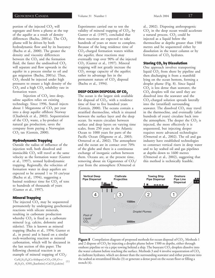
Storing CO2 by DissolutionOne approach involves transportingliquid CO2 from shore by pipeline andthen discharging it from a manifoldlying on the ocean bottom, forming adroplet plume (Fig. 8). Since liquidCO2 is less dense than seawater, theCO2 droplets will rise until they aredissolved into the seawater and theCO2-charged solution spreads laterallyinto the (stratified) surroundingseawater. The dissolved CO2 may travelin the thermocline, and eventually (afterhundreds of years) circulate back intothe atmosphere. The deeper the CO2 isinjected, the more effectively it issequestered, but injecting deeperrequires more advanced technologies(Ormerod et al., 2002). The oil and gasindustry have established technologiesto construct vertical risers in deep waterand to lay seabed oil and gas pipelinesat depths down to 1600 metres(Ormerod et al., 2002), suggesting thatthis method is technically feasible.
Figure 8 Figure 8 Figure 8 Figure 8 Figure 8 Compilation diagram of proposed methods for ocean disposal of CO2. Methods 1and 2 dispose of CO2 by injecting a droplet plume below 1500 m depths, either throughonshore pipeline or via a pipe towing behind a ship. The buoyant CO2 droplets dissolve intothe water column before reaching the surface. Methods 3 and 4 involve sequestration of CO2as clathrate hydrates, which are denser than the surrounding seawater and either penetrate intothe seabed as streamlined blocks (3) or generate a dense pool on the ocean floor or filling atrench (4).
18
Alternatively, liquid CO2 couldbe transported by a tanker anddischarged from a pipe towed by amoving ship (Fig. 8). The JapaneseR&D program for ocean sequestrationof CO2 is currently in phase II of alarge-scale “moving-ship” scheme in thewestern North Pacific to assessenvironmental impact and CO2-plumebehaviour (Murai et al., 2003). Studiesby Ozaki et al. (2001) have shown thatCO2 injection would be most effectiveat relatively slower rates (larger dropletsize) and at depths greater than 1500metres. Such a depth is well within thecapability of present-day subsea pipelinetechnology and CO2 could betransported by tankers, similar to thoseused for transportation of liquidpetroleum gas (Ormerod et al., 2002).
Storing CO2 as ClathratesAnother method for ocean disposal ofCO2 involves sequestration of CO2 atdepths in excess of 3000 metres. Atthese depths, because of the highpressure and low temperatures, CO2exists in the form of a clathrate hydrate,an ice-like combination of CO2 andwater (Brewer et al., 2000). Pure CO2-hydrate is denser than seawater and willgenerate a sinking plume, settling on thebottom of the ocean (Brewer et al.,2000). CO2 sequestered in this waywould form submarine pools in hollowsor trenches in the deep sea. Dissolutionof CO2 into the overlying seawaterwould be reduced significantly becauseof formation of the CO2-hydrates.Direct disposal of CO2 at great depthsis currently not technically feasible,however, it may be possible to send coldCO2 (dry ice) from mid-depth to theocean floor (Aya et al., 2003). With adensity greater than seawater, cold CO2will sink to the ocean bottom and beeffectively stored. The Monterey BayAquarium Research Institute (MBARI)has recently conducted a series ofcontrolled experiments that involverelease of cold CO2 slurry at depths of350 to 500 metres (Aya et al., 2003).
Yet another method proposesdisposal of CO2 as clathrate blocks.Studies on this disposal method confirmthat streamlined blocks have higherterminal velocity and thus reach theseabed faster than equidimensionalblocks (Guever et al., 1996). As large as
1000 tonnes and shaped like aprojectile, these blocks could penetrateinto the deep seabed where the solidCO2 would physically and chemicallyinteract with the sediments beforereacting with the ocean water (Fig. 8).The retention times could, therefore, besignificantly increased as compared tothe gaseous or liquid CO2 disposalmethods (Guever et al., 1996).According to the IEA this method iscurrently not economically feasible(Ormerod et al., 2002).
Further studies on oceandisposal of CO2 include fertilizing theoceans with additional nutrients toincrease draw-down of CO2 from theatmosphere (Ormerod et al., 2002).Addition of nutrients such as nitratesand phosphates or iron may increaseproduction of biological material,thereby drawing down additional CO2from the atmosphere throughphotosynthesis of the phytoplankton.Should this method prove to be feasible,the fishing industries may benefit fromthe resulting increase in the fishpopulation, with atmospheric CO2sequestration as a secondary benefit.However the overall impact on themarine ecosystem is not wellunderstood.
All the above-described oceandisposal methods could potentially causeat least a local change in pH of theocean water. Marine populations are, ingeneral, intolerant to changes in the pH.Thus, because of environmental impactson the marine ecosystem and associatedpublic disapproval, ocean sequestrationof CO2 is not currently considered asan attractive option.
STORAGE IN SALT CAVERNSSalt can be found as evaporite beds oras intrusive (domal or ridge) depositswhere salt from a major underlyingsource has been forced up intooverlying formations. The WesternCanada Sedimentary Basin containsseveral regionally extensive salt deposits,contained primarily within strata of theDevonian Elk Point Group (Grobe,2000). Large cavities are created bysolution mining, whereby water isinjected into a salt bed or dome and thebrine solution is pumped out. Thesecaverns can be up to 5x10⁵ m3 involume (Bachu, 2000), and since salt is
highly impermeable (Murck et al.,1996), these spaces could provide along-term solution to CO2sequestration. The technology has beendeveloped and applied for salt miningand underground storage of liquidpetroleum gas (LPG), compressed airand petrochemicals (Bachu, 2000;Crossley, 1998; Istvan, 1983). SolidCO2 (dry ice) could also be stored inthese repositories, surrounded bythermal insulation to minimize heattransfer and loss of CO2 gas (Davison etal., 2001). Although salt and rockcaverns theoretically have a large storagecapacity, the associated costs are veryhigh and the environmental problemsrelating to the mined rock and disposalof large amounts of brine are significant(Kolkas-Mossbah and Friedman, 1997).Using current technology, storage ofCO2 in underground salt caverns isuneconomical.
MINERAL CARBONATIONBased on a natural rock-weatheringreaction, mineral carbonation is asequestration concept whereby CO2 ischemically combined in an exothermicreaction with readily available Mg orCa-silicate minerals to form carbonates(Lackner et al., 1997; O’Connor et al.,2000; Gerdemann et al., 2003). Theproducts are stable on a geologic time-scale, potentially storing CO2 formillions of years. Mg-silicates arefavoured relative to Ca-silicates becausethey are more widespread, form largerbodies and contain more reactivematerial per tonne of rock (Lackner etal., 1997; Kohlmann et al., 2002). Awide variety of Mg-bearing materials,such as enstatite, fly ash and otherindustrial residues were investigated aspotential starting materials for theindustrial carbonation process. Recentlaboratory tests however, indicate thatolivine [(Mg,Fe)SiO4] and serpentine[Mg3Si2O5(OH)4] are the mostpromising raw material (e.g. Lackner etal., 1997; O’Connor et al., 2000). Thetwo reactions below illustrate the basicCO2 carbonation principle using olivineand serpentine as examples:
(2)Mg2SiO4[olivine]+ 2CO2 =>
2MgCO3[magnesite]+ SiO2
Mg3SiO3(OH)4[serpentine]+ 3CO2 =>
3MgCO3[magnesite]+2SiO2 + H2O(3)
GEOSCIENCE CANADA Volume 31 Number 1 March 2004 19
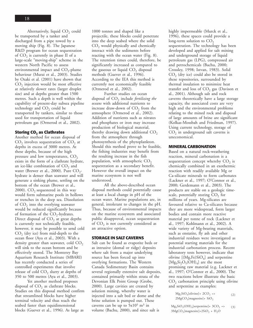
In nature, carbonation reactionsinvolving silicates are slow (Kohlmannand Zevenhoven, 2001). A sequestra-tion plant can be visualized as a blenderoperating at high temperature andpressure conditions (Fig. 9). Forindustrial CO2 sequestrationapplications, carbonation reactions haveto be accelerated. This can be achievedby increasing the surface area of theMg-silicate (crushing and milling),agitating the slurry (O’Connor et al.,1999; Dahlin et al., 2000) and byadding catalysts (for example, NaCl andNaHCO3 and HCl) to the solution/slurry prior to the carbonation process(Dahlin et al., 2000; Goldberg andWalters, 2003; Jia and Anthony, 2003;Fauth and Soong, 2001; Lackner et al.,1998). Optimization of the carbonationprocess by controlling temperature andpartial pressure of CO2 (PCO2) may bealso a major factor (O’Connor et al.,1999; Dahlin et al., 2000). In the caseof serpentine, an energy-intensive heatpre-treatment (activation-destabilizationof the crystal structures) at temperaturesof 600 to 650°C is required (O’Connoret al., 2000). Such pre-treatmentremoves chemically bound water andincreases overall porosity (Gerdemannet al., 2003; Kohlmann et al., 2002;Goldberg and Walters, 2003), therebyenhancing its mineral carbonationpotential.
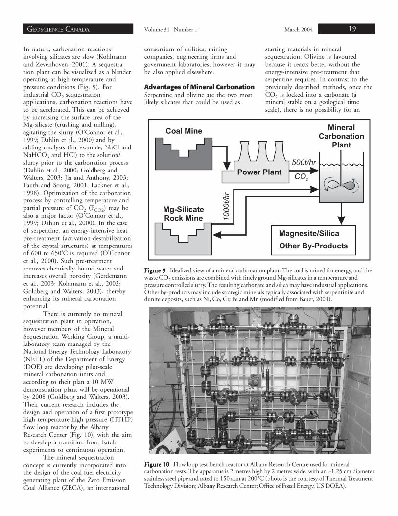
There is currently no mineralsequestration plant in operation,however members of the MineralSequestration Working Group, a multi-laboratory team managed by theNational Energy Technology Laboratory(NETL) of the Department of Energy(DOE) are developing pilot-scalemineral carbonation units andaccording to their plan a 10 MWdemonstration plant will be operationalby 2008 (Goldberg and Walters, 2003).Their current research includes thedesign and operation of a first prototypehigh temperature-high pressure (HTHP)flow loop reactor by the AlbanyResearch Center (Fig. 10), with the aimto develop a transition from batchexperiments to continuous operation.
The mineral sequestrationconcept is currently incorporated intothe design of the coal-fuel electricitygenerating plant of the Zero EmissionCoal Alliance (ZECA), an international
Figure 10 Figure 10 Figure 10 Figure 10 Figure 10 Flow loop test-bench reactor at Albany Research Centre used for mineralcarbonation tests. The apparatus is 2 metres high by 2 metres wide, with an ~1.25 cm diameterstainless steel pipe and rated to 150 atm at 200°C (photo is the courtesy of Thermal TreatmentTechnology Division; Albany Research Center; Office of Fossil Energy, US DOEA).
FFFFFigurigurigurigurigure 9 e 9 e 9 e 9 e 9 Idealized view of a mineral carbonation plant. The coal is mined for energy, and thewaste CO2 emissions are combined with finely ground Mg-silicates in a temperature andpressure controlled slurry. The resulting carbonate and silica may have industrial applications.Other by-products may include strategic minerals typically associated with serpentinite anddunite deposits, such as Ni, Co, Cr, Fe and Mn (modified from Bauer, 2001).
consortium of utilities, miningcompanies, engineering firms andgovernment laboratories; however it maybe also applied elsewhere.
Advantages of Mineral CarbonationSerpentine and olivine are the two mostlikely silicates that could be used as
starting materials in mineralsequestration. Olivine is favouredbecause it reacts better without theenergy-intensive pre-treatment thatserpentine requires. In contrast to thepreviously described methods, once theCO2 is locked into a carbonate (amineral stable on a geological timescale), there is no possibility for an
20
accidental release of CO2. As well,direct carbonation does not lead toproblematic by-products (Lackner et al.,1998). Furthermore, should fibrousserpentine tailings (chrysotile) beconsidered as raw material for theprocess (e.g. Huot et al., 2003), thenmineral sequestration would helpdispose of unwanted asbestos waste.Mineral carbonation may, therefore,benefit from public acceptance.
The costs of the CO2 disposalcould be higher than for the injection ofCO2 into oil and gas reservoirs or deepcoal seams, for example. However,these costs may be reduced if thepotential for industrial applications ofthe product (depending on acceptablepurity, grain size, particle shape andchemical properties). Magnesite has awide variety of industrial applications(Simandl, 2002) and the same appliesfor silica. The carbonation process mayalso become a new source of Fe, Mn,Co, Cr and Ni recovered during thebreakdown of Mg silicate’s crystalstructure (Haywood et al., 2001;O’Connor et al., 2000).
Large-scale CO2 sequestrationinto carbonates will require enormousamounts of raw material (Kohlmann etal., 2002). For a typical power plant, themass flows of fuel and carbonatedmineral will be of the same order ofmagnitude. For example, studiessuggests that for a single 500 MW coal-fired power plant, generatingapproximately 10 000 tons of CO2 perday, more than 23 000 to 30 000 tonsper day of Mg-silicate ore would berequired (Dahlin et al., 2000;O’Connor et al., 2000). Thus, underideal conditions, coal and Mg-silicatemines should be located close to eachother. No shortage of starting materialis likely to occur if mineralsequestration becomes a reality andserpentine becomes a workhorse ofmineral CO2 sequestration (Goff et al.,1997). However, if forsterite (Mg-endmember of olivine) is used as startingmaterial, supplies are limited andgeographically constrained. In mostcases, serpentine is an unwanted by-product of metal and chrysotile mining,but in some locations, this waste maybecome a sought after commodity whenits potential for CO2 sequestration isrealized. Should mineral sequestration
of CO2 become an establishedtechnology, then new opportunities willarise for potential producers ofmagnesium silicates and owners ofmagnesium silicate-rich tailings.
CONCLUSIONSThis paper presents descriptions of themain geological, ocean and mineralCO2 sequestration methods that arecurrently the focus of intensive researchby industrialized nations worldwide. Atfirst glance, the most technologicallymature methods are storage in activeand depleted oil and gas fields, thoughmost of the emphasis lies onmaximizing oil and gas recovery ratherthan sequestration potential. Researchrelating to injection of CO2 into deepcoal seams is rapidly advancing, withCO2-enhanced CBM recoverypotentially offsetting sequestration costs.Saline aquifers provide huge storagepotential in terms of volume for CO2sequestration, but they are much moredifficult and expensive to characterizethan hydrocarbon reservoirs because ofthe lack of an existing explorationdatabase. The methods that currentlyencounter the most resistance from thepublic are storage in salt caverns andocean sequestration. Mineralsequestration is the only method thattruly disposes of CO2 on geologicaltime scale, with a minimum risk for anaccidental CO2 release.
ACKNOWLEDGMENTSWe would like to thank Terry P.McCullough of BC Hydro, Barry Ryan,Brian Grant and Derek Brown ofBritish Columbia Ministry of Energyand Mines and Alan Johnson fromZECA Corporation for reviewing theearlier version of this manuscript. Themanuscript was greatly improved byincorporating suggestions from StefanBachu of Alberta Energy and UtilitiesBoard and Steve Whittaker ofSaskatchewan Industry and Resources.
REFERENCESArri, L.E., Yee, D., Morgan, W.D., and
Jeansonne, M.W., 1992, Modeling coalbedmethane production with binary gassorption: Society of Petroleum Engineers,Paper No. 24363, p. 459-472.
Aya, I., Kojima, R., Yamane, K., Brewer, P.G.,and Peltzer, III, E.T., 2003, In situexperiments of cold CO2 release in mid-
depth, in Gale J. and Kaya, Y., eds.,Proceedings of the 6th InternationalConference on Greenhouse Gas ControlTechnologies, Volume I: Elsevier ScienceLtd., London UK, p. 739-744.
Aycaguer, A. Lev-On, M., and Winer, A.M.,2001, Reducing carbon dioxide emissionswith enhanced oil recovery projects: a lifecycle assessment approach: Energy andFuels, v. 15, p. 303-308.
Bachu, S., 2000, Sequestration of CO2 ingeological media: criteria and approach forsite selection in response to climate change:Energy Conversion & Management, v. 41(9), p. 953-70.
Bachu, S., 2001a, Suitability of the WesternCanada Sedimentary Basin for CO2Sequestration and Capacity in Oil and GasReservoirs, September 2001:<http://www.ptac.org/env/dl/envf0202pp.pdf>
Bachu, S., 2001b, Identification of best sitesand means for CO2 sequestration in theAlberta Basin, Canada [abstract]: AmericanAssociation of Petroleum Geologists, AnnualMeeting, 2001, 9 p.
Bachu, S. and Gunter B., 2003, Acid gasinjection in Western Canada: IEAGreenhouse Issues, No. 67, July 2003.
Bachu, S., Gunter, W.D., and Perkins, E.H.,1994, Aquifer disposal of CO2:Hydrodynamic and mineral trapping: EnergyConversion & Management, v. 35, p. 269-279.
Bachu, S., Brulotte, M., Brobe, M., andStewart, S., 2000, Suitability of the Albertasubsurface for carbon-dioxide sequestrationin geological media: Earth Sciences Report,Alberta Research Council, Edmonton, AB,Canada, 86 p.
Bauer, C.O., 2001, Overview- MineralCarbonation Workshop:<www.netl.doe.gov/publications/proceedings/01/minecarb/Bauer.pdf>
Benson, S.M., 2000, An overview of geologicsequestration of CO2: Proceedings of the 8th
International Energy Forum, Presented andPublished in ENERGEX, Las Vegas, NV,p. 1219-1225.
Benson, S.M., Hepple, R., Apps, J., Tsang, C.F.,and Lippmann, M., 2002, Comparativeevaluation of risk assessment, managementand mitigation approaches for deep geologicstorage of CO2: E.O. Lawrence BerkeleyNational Laboratory, LBNL-51170, 133 p.
Brewer, P.G., Peltzer, E.T., Friederich, G., Aya,I., and Yamane, K., 2000, Experiments onthe ocean sequestration of fossil fuel CO2:pH measurements and hydrate formation:Marine Chemistry, v. 72, p. 83-93.
Chadwick, R.A., Zweigel, P., Gregersen, U.,Kirby, G.A., Holloway, S., and Johannessen,P.N., 2003, Geological characteristics ofCO2 storage sites: lessons from Sleipner,northern North Sea, in Gale, J. and Kaya,Y., eds., Proceedings of the 6th InternationalConference on Greenhouse Gas ControlTechnologies, Volume I: Elsevier ScienceLtd., London UK, p. 321-326.
GEOSCIENCE CANADA Volume 31 Number 1 March 2004 21
City of Toronto, 1991, The urban CO2reduction project: international Council forLocal Environmental Initiatives, a profile ofthe City of Toronto and the Municipality ofMetropolitan Toronto, November 1991.
Crossley, N.G., 1998, Conversion of LPG saltcaverns to natural gas storage “A TransGasExperience”: Journal of Canadian PetroleumTechnology, v. 37 (12), p. 37-47.
Dahlin, D.C., O’Connor, W.K., Nilsen, D.N.,Rush, G.E., Walters, R.P., and Turner, P.C.,2000, A method for permanent CO2sequestration: supercritical CO2 mineralcarbonation: Proceedings of the 17th AnnualInternational Pittsburgh Coal Conference,Pittsburgh, Pennsylvania.
Davison, J., Freund, P., and Smith, A., 2001,Putting carbon back in the ground: IEAGreenhouse Gas R&D Programme, ISBN 1898 373 28 0, p. 26.
Environment Canada, 2002, Canada’sgreenhouse gas inventory 1990-2000:Greenhouse gas Division, June 2002, http://www.ec.gc.ca/.
Fauth, D.J. and Soong, Y., 2001, Mineralsequestration utilizing industrial by-products, residues, and minerals: NationalEnergy Technology Laboratory (NETL),Mineral Carbonation Workshop.
Fokker, P.A. and van der Meer, L.G.H., 2003,The injectivity of coalbed CO2 injectionwells, in Gale, J. and Kaya, Y., eds.,Proceedings of the 6th InternationalConference on Greenhouse Gas ControlTechnologies, Volume I: Elsevier ScienceLtd., London UK, p. 551-556.
Gale, J., 2003, Geological storage of CO2:What’s known, where are the gaps and whatmore needs to be done, in Gale, J. and Kaya,Y. eds., Proceedings of the 6th InternationalConference on Greenhouse Gas ControlTechnologies, Volume I: Elsevier ScienceLtd., London UK, p. 207-212.
Gentzis, T., 2000, Subsurface sequestration ofcarbon dioxide - an overview from anAlberta (Canada) perspective: InternationalJournal of Coal Geology, v. 43, p. 287-305.
Gerdemann, S.J., Dahlin, D.C., and O’Connor,W.K., 2003, Carbon dioxide sequestrationby aqueous mineral carbonation ofmagnesium silicate minerals, in Gale, J. andKaya, Y., eds., Proceedings of the 6th
International Conference on GreenhouseGas Control Technologies, Volume I,Elsevier Science Ltd., London UK, p. 677-678.
Goff, F., Guthrie, G., Counce, D., Kluk, E.,Bergfeld, D., and Snow, M., 1997,Preliminary investigations on the carbondioxide sequestering potential of ultramaficrocks: Los Alamos National Laboratory, LA-13328-MS, 22 p.
Goldberg, P. and Walters, R., 2003, A programto develop CO2 sequestration via mineralcarbonation, in Gale, J. and Kaya, Y. eds.,Proceedings of the 6th InternationalConference on Greenhouse Gas Control
Technologies, Volume I: Elsevier ScienceLtd., London UK, p. 665-669.
Grobe, M., 2000, Distribution and thickness ofsalt within the Devonian Elk Point Group,Western Canada Sedimentary Basin: EarthSciences Report 2000, Alberta ResearchCouncil, 16 p.
Guever, P., Fruman, D.H., and Murray, N.,1996, Conceptual design of an integratedsolid CO2 penetrator marine disposalsystem: Energy Conversion & Management,v. 37 (6-8), p. 1053-1060.
Gunter, W.D., Wiwchar, B., and Perkins, E.H.,1997, Aquifer disposal of CO2-richgreenhouse gases: extension of the time scaleof experiment for CO2-Sequesteringreactions by geochemical modeling:Mineralogy and Petrology, v. 59, p. 121-140.
Gunter, W.D., Bachu, S., and Benson, S.M., (inpress), The role of hydrogeological andgeochemical trapping in sedimentary basinsfor secure geological storage for carbondioxide, in Geological Storage of CarbonDioxide for Emissions Reduction:Technology, Baines, S.J. and Worden, R.H.,eds., Geological Society Special Publication,Bath, U.K., 25 p.
Haywood, H.M., Eyre, J.M., and Scholes, H.,2001, Carbon dioxide sequestration asstable carbonate minerals; environmentalbarriers: Environmental Geology (Berlin), v.41 (1-2), p. 11-16.
Hitchon, B., Gunter, W.D., Gentzis, T., andBailey, R.T., 1999, Sedimentary basins andgreenhouse gases: a serendipitousassociation: Energy Conversion &Management, v. 40 (8), p. 825-43.
Huang, S., 2001, CO2 Flooding - A goldenopportunity for black gold and theenvironment: Saskatchewan BusinessMagazine, 2001, September/October, p. 13.
Huot, F., Beaudoin, G., Hebert, R.,Constantine, M., Bonin, G., and Dipple,G.M., 2003, Evaluation of southern Quebecasbestos residues for CO2 sequestration bymineral carbonation; preliminary result:Abstract, GAC-MAC-SEG Conference,Vancouver, 2003.
International Energy Agency Greenhouse GasR&D Programme, 2001, www.ieagreen.org.uk.
Istvan, J.A., 1983, Storage of natural gas in saltcaverns [abstract]: Proceedings of the 6th
Salt Symposium, Toronto, May 26-27th,25 p.
Ivory, J., Gunter, W.D., Law. D., and Wong, S.,2000, Recovery of CO2 from flue gas, CO2sequestration, and methane production fromcoalbed methane reservoirs: Proceedings ofthe International Symposium onEcomaterials, Ottawa, August 20-23, p.487-501.
Jia, L. and Anthony, E.J., 2003, Mineralcarbonation and Zeca, in Gale, J. and Kaya,Y., eds., Proceedings of the 6th InternationalConference on Greenhouse Gas ControlTechnologies, Volume I: Elsevier ScienceLtd., London UK, p. 671-676.
Jimenez, J.A. and Chalaturnyk, R.J., 2003: Aredisused hydrocarbon reservoirs safe for thegeological storage of CO2?, in Gale, J. andKaya, Y., eds., Proceedings of the 6th
International Conference on GreenhouseGas Control Technologies, Volume I:Elsevier Science Ltd., London UK, p. 471-475.
Kohlmann, J. and Zevenhoven, R., 2001, Theremoval of CO2 from flue gases usingmagnesium silicates, in Finland: Proceedingsof the 11th International Conference on CoalScience, San Francisco, California.
Kohlmann, J., Zevenhoven, R., and Mukherjee,A.B., 2002, Carbon dioxide emission controlby mineral carbonation: the option forFinland: Proceedings of the 6th EuropeanConference on Industrial Furnaces andBoilers, Estoril Lisbon, Portugal.
Koide, H., Tazaki, Y., Noguchi, Y., Iijima, M.,Ito, K., and Shindo, Y., 1996, Undergroundstorage of carbon dioxide in depleted naturalgas reservoirs and in useless aquifers:Engineering Geology, v. 34, p. 175-179.
Kolkas-Mossbah, M. and Friedman, G.M.,1997, Subsurface brine disposal in theCambro-Lower Ordovician of central andwestern New York: implications for newsalt-cavern gas storage reservoirs: AmericanAssociation of Petroleum Geologists,Bulletin, v. 81 (8), p. 1390.
Krooss, B.M., van Bergen, F., Gensterblum, Y.,Siemons, N., Pagnier, H.J.M., and David, P.,2002, High-pressure methane and carbondioxide adsorption on dry and moisture-equilibrated Pennsylvanian coals:International Journal of Coal Geology, v. 51,p. 69-92.
Lackner, K.S., Butt, D.P., and Wendt, C.H.,1997, Magnesite disposal of carbon dioxide:Proceedings of the 22nd InternationalTechnical Conference on Coal Utilization &Fuel Systems, Clearwater, Florida, p. 419-430.
Lackner, K.S., Butt, D.P., Wendt, C.H., andZiock, H., 1998, Mineral carbonates ascarbon dioxide sinks: Los Alamos NationalLaboratory, Los Alamos, LA-UR-98-4530,9 p.
Law, D.H.S., van der Meer, L.H.G., andGunter, W.D., 2003, Comparison ofnumerical simulators for greenhouse gasstorage in coalbeds, Part II: Flue gasinjection, in Gale, J. and Kaya, Y., eds.,Proceedings of the 6th InternationalConference on Greenhouse Gas ControlTechnologies, Volume I: Elsevier ScienceLtd., London UK, p. 563-568.
Macdonald, D., Wong, S., Gunter, B., Nelson,R., and Reynen, B., 2003, Surface facilitiescomputer model: an evaluation tool forenhanced coalbed methane recovery, inGale, J. and Kaya, Y., eds., Proceedings ofthe 6th International Conference onGreenhouse Gas Control Technologies,Volume I: Elsevier Science Ltd., LondonUK, p. 575-580.
22
Mavor, M.J., Gunter, W.D., Robinson, J.R.,Law, D.H.S., and Gale, J., 2002, Testing forCO2 sequestration and enhanced methaneproduction from coal [abstract]: SPE Paper75680, Presented at the SPE GasTechnology Symposium, May 30-June 2,Calgary, 14 p.
McKee, B., 2002, Solutions for the 21st
century- Zero emissions technology for fossilfuels: International Energy Agency, 48 p.
Mignone, B.K., Sarmiento, J.L., Slater, R.D.,and Gnanadesikan, A., 2003, Sensitivity ofsequestration efficiency to mixing processesin the global ocean, in Gale, J. and Kaya, Y.,eds., Proceedings of the 6th InternationalConference on Greenhouse Gas ControlTechnologies, Volume I: Elsevier ScienceLtd., London, UK, p. 725-731.
Moberg, R., 2001, The Weyburn CO2monitoring and storage project: GreenhouseIssues, IEA Greenhouse Gas R&DProgramme, v. 57.
Moberg, R., Stewart, D.B., and Stachniak, D.,2003, The IEA Weyburn CO2 monitoringand storage project: in Gale, J. and Kaya, Y.,eds., Proceedings of the 6th InternationalConference on Greenhouse Gas ControlTechnologies, Volume I: Elsevier ScienceLtd., London, UK, p. 219-224.
Murai, S., Ohsumi, T., Nishibori, F., and Ozaki,M., 2003, The second phase of JapaneseR&D program for CO2 ocean sequestration,in Gale, J. and Kaya, Y., eds., Proceedings ofthe 6th International Conference onGreenhouse Gas Control Technologies,Volume I: Elsevier Science Ltd., London,UK, p. 733-738.
Murck, B.W., Skinner, B.J., and Porter, S.C.,1996, Environmental geology: John Wiley& Sons, Inc., 476 p.
O’Connor, W.K., Dahlin, D.C., Turner, P.C.,and Walters, R.P., 1999, Carbon dioxidesequestration by ex-situ mineralcarbonation: Proceedings of the 2nd DixyLee Ray Memorial Symposium: Utilizationof Fossil Fuel-Generated Carbon Dioxide inAgriculture and Industry, Washington, D.C.
O’Connor, W.K., Dahlin, D.C., Nilsen, D.N.,Walters, R.P., and Turner, P.C., 2000,Carbon dioxide sequestration by directmineral carbonation with carbonic acid:Proceedings of the 25th InternationalTechnical Conference on Coal Utilization &Fuel Systems, Coal Technology Association,Clearwater, Florida.
Oldenburg, C.M., Pruess, K., and Benson,S.M., 2001, Process modeling of CO2injection into natural gas reservoirs forcarbon sequestration and enhanced gasrecovery: Energy & Fuels, v. 15, p. 293-298.
Oldenburg, C.M. and Benson, S.M., 2002,CO2 injection for enhanced gas productionand carbon sequestration: Proceedings ofthe SPE International PetroleumConference and Exhibition, Mexico, Societyof Petroleum Engineers, 10-12 February,2002.
Ormerod, W.G., Freund, P., and Smith, A.,2002, Ocean storage of CO2: IEA
Greenhouse Gas R&D Programme, ISBN 1898 373 30 2, 26 p.
Ozaki, M., Minamitura, J., Kitajima, Y,Mizokami, S., Takeuchi, K., andHatakenaka, K., 2001, CO2 oceansequestration by moving ships: Journal ofMarine Science and Technology, v. 6, p. 51-58.
Reeve, D.A., 2000, The capture and storage ofcarbon dioxide emissions- a significantopportunity to help Canada meet its Kyototargets: prepared under NRCan ContractFile No. NRCan-00-0195, Office of EnergyResearch and Development, NaturalResources Canada, Global ChangeStrategies International Inc., 20 p.
Reeves, S., 2003, Coal-Seq project update: fieldstudies of ECBM recovery/CO2sequestration in coal seams, in Gale, J. andKaya, Y., eds., Proceedings of the 6th
International Conference on GreenhouseGas Control Technologies, Volume I:Elsevier Science Ltd., London, UK, p. 557-562.
Rice, D.D., Law, B.E., and Clayton, J.L., 1993,Coalbed gas- an undeveloped resource, inHowell, D.G., ed., The Future of EnergyGases: U.S. Geological Survey ProfessionalPaper 1570, p. 389-404.
Schraufnagel, R.A., 1993, Coalbed methaneproduction, in Law, B.E. and Rice, D.D.,eds., Hydrocarbons From Coal: AmercianAssociation of Petroleum Geologists, Studiesin Geology, v. 38, p. 341-359.
Shi, J.Q., Durucan, S., and Sinka, I.C., 2002,Key parameters controlling coalbed methanecavity well performance: InternationalJournal of Coal Geology, v. 49, p. 19-31.
Simandl. G.J., 2002, The chemicalcharacteristics and development potential ofmagnesite deposits in British Columbia,Canada, in Scott, P.W. and Bristow, C.M.,eds., Industrial Minerals and ExtractiveIndustry Geology: Geological Society,London, p. 169-178.
Smith, L.K., 1998, Carbonate cementdissolution during a cyclic CO2 enhanced oilrecovery treatment: Special Publication ofthe International Association ofSedimentologists, v. 26, p. 483-499.
Stevens, S.H., Kuuskraa, V.A., and Gale, J.,2000, Sequestration of CO2 in depleted oil& gas fields: Global capacity, costs andbarriers: Proceedings from the 5th
International Conference on GreenhouseGas Control Technologies, CSIROPublishing, Collingwood, Australia.
Thambimuthu, K., Mercier, G., Wilson, M.,Mitchell, B., and Ali, M., 2003, Canadianinitiatives on CO2 capture and storage:towards zero emissions from fossil fuels, inGale, J. and Kaya, Y., eds., Proceedings ofthe 6th International Conference onGreenhouse Gas Control Technologies,Volume I: Elsevier Science Ltd., London,UK, p. 1151-1156.
Tontiwachwuthikul, P., Chan, C.W.,Kritpiphat, W., Demontigny, D.,
Skoropad, D., Gelowitz, D., Aroonwilas, A.,Mourits, F., Wilson, M., and Ward, L.,1998, Large scale carbon dioxide productionfrom coal-fired power stations for enhancedoil recovery: a new economic feasibilitystudy: The Journal of Canadian PetroleumTechnology, v. 37 (11), p. 48-55.
U.S. Department of Energy, 2002, Carbonsequestration technology roadmap:pathways to sustainable use of fossil energy:Office of Fossil Energy, National EnergyTechnology Laboratory (NETL), 22 p.
Van Bergen, F. and Pagnier, H.J.M., 2001, CO2Sequestration in coal - a potentially cleanenergy cycle: Greenhouse Issues, IEAGreenhouse Gas R&D Programme, v. 56.
Van Bergen, F., Pagnier, H.J.M, van der Meer,L.G.H., van den Belt, F.J.G., Winthaegen,P.L.A., and Westerhoff, R.S., 2003,Development of a field experiment of CO2storage in coal seams in the Upper SilesianBasin of Poland (Recopol), in Gale, J. andKaya, Y., eds., Proceedings of the 6th
International Conference on GreenhouseGas Control Technologies, Volume I:Elsevier Science Ltd., London, UK, p. 569-574.
Van der Meer, L.G.H., 1993, The conditionslimiting CO2 storage in aquifers: EnergyConversion and Management, v. 34, p. 959-966.
Van der Meer, L.G.H., 2003, CO2 storage inthe subsurface, in Gale, J. and Kaya, Y.,eds., Proceedings of the 6th InternationalConference on Greenhouse Gas ControlTechnologies, Volume I: Elsevier ScienceLtd., London, UK, p. 201-206.
Voormeij, D.A. and Simandl, G.J., 2003, BritishColumbia’s CO2 sequestration options: CO2sinks and major stationary point sources:Geofile 2003-11, British ColumbiaGeological Survey Branch.
Whittaker, S.G. and Rostron, B., 2003,Geological storage of CO2 in a carbonatereservoir within the Williston Basin,Canada: an update, in Gale, J. and Kaya, Y.,eds., Proceedings of the 6th InternationalConference on Greenhouse Gas ControlTechnologies, Volume I: Elsevier ScienceLtd., London, UK, p. 385-390.
Wong, S. and Gunter, B., 1999, Testing CO2-enhanced coalbed methane recovery:Greenhouse Issues, IEA Greenhouse GasR&D Programme, v. 45.
Wong, S., Gunter, W.D., and Mavor, M.J.,2000, Economics of CO2 sequestration incoalbed methane reservoirs: Proceedings ofSPE/CERI Gas Technology Symposium2000, SPE 59785, April 3-5, Calgary,Alberta, p. 631-638.
Wong, S., MacLeod, K., Wold, M., Gunter,W.D., Mavor, M.J., and Gale, J., 2001,CO2-enhanced coalbed methane recoverydemonstration pilot- a case for Australia:Proceedings of the 2001 InternationalCoalbed Methane Symposium, May 14-18,Alabama, U.S., p. 75-86.
Accepted as revised 22 December 2003