Embed Size (px)
Citation preview
GEOLUX GL 660-1For location of earth faults in IT-networks
GEOLUX GL 660-1For earth fault location in IT-networks
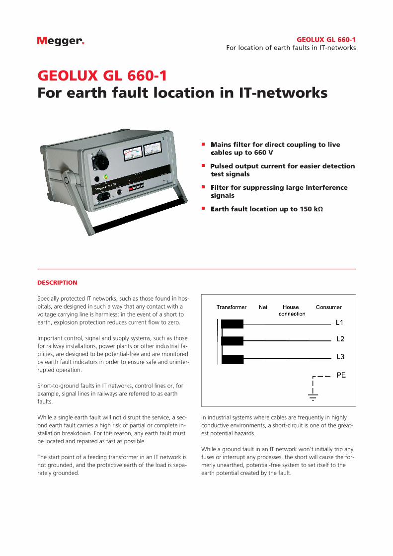
Specially protected IT networks, such as those found in hos-pitals, are designed in such a way that any contact with a voltage carrying line is harmless; in the event of a short to earth, explosion protection reduces current ow to zero.
Important control, signal and supply systems, such as those for railway installations, power plants or other industrial fa-cilities, are designed to be potential-free and are monitored by earth fault indicators in order to ensure safe and uninter-rupted operation.
Short-to-ground faults in IT networks, control lines or, for example, signal lines in railways are referred to as earth faults.
While a single earth fault will not disrupt the service, a sec-ond earth fault carries a high risk of partial or complete in-stallation breakdown. For this reason, any earth fault must be located and repaired as fast as possible.
The start point of a feeding transformer in an IT network is not grounded, and the protective earth of the load is sepa-rately grounded.
Mains lter for direct coupling to live cables up to 660 V
Pulsed output current for easier detection test signals
Filter for suppressing large interference signals
Earth fault location up to 150 kΩ
Mains lter for direct coupling to live cables up to 660 V
Pulsed output current for easier detection test signals
Filter for suppressing large interference signals
Earth fault location up to 150 kΩ
DESCRIPTION
In industrial systems where cables are frequently in highly conductive environments, a short-circuit is one of the great-est potential hazards.
While a ground fault in an IT network won’t initially trip any fuses or interrupt any processes, the short will cause the for-merly unearthed, potential-free system to set itself to the earth potential created by the fault.
2
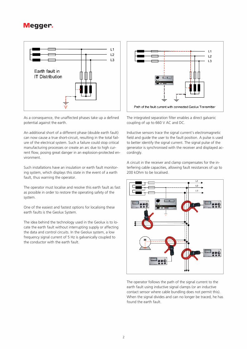
As a consequence, the unaffected phases take up a de ned potential against the earth.
An additional short of a different phase (double earth fault) can now cause a true short-circuit, resulting in the total fail-ure of the electrical system. Such a failure could stop critical manufacturing processes or create an arc due to high cur-rent flow, posing great danger in an explosion-protected en-vironment.
Such installations have an insulation or earth fault monitor-ing system, which displays this state in the event of a earth fault, thus warning the operator.
The operator must localise and resolve this earth fault as fast as possible in order to restore the operating safety of the system.
One of the easiest and fastest options for localising these earth faults is the Geolux System.
The idea behind the technology used in the Geolux is to lo-cate the earth fault without interrupting supply or affecting the data and control circuits. In the Geolux system, a low frequency signal current of 5 Hz is galvanically coupled to the conductor with the earth fault.
The integrated separation lter enables a direct galvanic coupling of up to 660 V AC and DC.
Inductive sensors trace the signal current’s electromagnetic eld and guide the user to the fault position. A pulse is used to better identify the signal current. The signal pulse of the generator is synchronised with the receiver and displayed ac-cordingly.
A circuit in the receiver and clamp compensates for the in-terfering cable capacities, allowing fault resistances of up to 200 kOhm to be localised.
The operator follows the path of the signal current to the earth fault using inductive signal clamps (or an inductive contact sensor where cable bundling does not permit this). When the signal divides and can no longer be traced, he has found the earth fault.

3
Seba DynatronicMess- und Ortungstechnik GmbHDr.-Herbert-Iann-Str. 696148 BaunachT +49 (0) 9544 680F +49 (0) 9544 [email protected]
Hagenuk KMTKabelmesstechnik GmbHRöderaue 4101471 RadeburgT +49 (0) 35208 840F +49 (0) 35208 [email protected]
CERTIFICATION ISO
Registered to ISO 9001 Cert. no. 000677 QM08
GL660_DS_EN_V02
www.megger.deMegger is a registered trademark
GERMANYMegger GmbHObere Zeil 2D-61440 OberurselT +49 6171 92987 0F +49 6171 92987 [email protected]
TECHNICAL DATA*
* We reserve the right to make technical changes.
Receiver GLE 660-1
Ampli cation 70 dB ... 100 dB
Filter 16.66 and 50 Hz Notch
Power supply 8 x 1.5 V AA batteries (LR 6)
Operating time approx. 40 hours
Operation temperature - 10 oC ... + 50 oC
Storage temperature - 25 oC ... + 70 oC
Max. rel. humidity < 80 %
Weight approx. 1.2 kg
Dimensions (W x H x D) 220 mm x 100 mm x 130 mm
Transmitter GLE 660-1
Power supply Mains 230 V, 45 ... 60 Hz
Battery (rechargeable) 12 V / 2,4 Ah
Operating time at 80 V approx. 5 h
Transmitter frequency 5 Hz +/- 0.1 Hz
Externel dielectric strength 660 V AC/DC
Operating temperature - 10 oC ... + 50 oC
Storage temperature - 25 oC ... + 70 oC
Weight approx. 12 kg
Dimensions (W x H x D) 366 mm x 183 mm x 260 mm
ORDERING INFORMATIONProduct Order no.
Earth fault locator with compensation 813178
Receiver with compensation, carrying strap, generator 5 Hz, set of cables for generator, probe for round conductor, reader clamp 100 mm
compensated, connection lead for reader clamp, identi cation tongs 12 mm compensated, carrying case for generator and receiver
Options:
Cable drum for compensation 810216
Probe for earth cable 810251
Connection lead for GS 5 810003828
STANDARD ACCESSORIES
SPECIAL ACCESSORIES
Reader clamps AZK 100, 100 mm, compensated
Hight voltage cable HSK 7-B
Connection cable VK 50, 10 m
Probe for round conductor GSK 1
Reader clamp AZK 12, 12 mm
Cable drum for compensation KTG 50, 50 m
Probe for earth cable GS 5