Embed Size (px)
Citation preview
1
R Basu and S Basu
TITLE PAGE 1
2
Geometric Design of Hill Roads to Minimize Natural Disaster Damages 3
Ranadeep Basu (M.Tech., MIE)1, Sridebi Basu (PhD, MIE)2 4
5
1Principal Engineer, Roads and Rail, COWI India Pvt. Ltd., Gurgaon, 6
24D/C, SFS Flats, Mayur Vihar-III, Delhi-110096, India; +91 9810537423; 7
2Chief Executive Officer, Save Earth Consultancy, 24D/C, SFS Flats, Mayur Vihar-III, 9
Delhi-110096, India; +91 9818673778; [email protected] 10
11
Submission date : 20th March 2015 12
13
Corresponding Author : Ranadeep Basu (M.Tech., MIE) 14
Principal Engineer, Roads and Rail, 15
COWI India Pvt. Ltd., Gurgaon 16
24D/C, SFS Flats, Mayur Vihar-III, Delhi-110096, India; 17
GSM : +91 9810537423 18
e-mail : [email protected] 19
20
Word Count: Abstract, Body & References = 4,322 Words (excl. tables & 21
figures) 22
Tables =4 nos. (4 x 250 words) = 1,000 Words 23
Figures = 3 nos. (3 x 250 words) = 750 Words 24
Total = 6,072 Words 25
26
27
2
R Basu and S Basu
1
ABSTRACT 2
The northern Indian states which lie in the Himalayan range are susceptible to different kind 3
of natural disasters every year. The major types of disasters are landslides, flash floods, 4
avalanche and earthquake. Disasters cause damages ranging from minor blockage to total 5
destruction of the road formation and disconnect villages and towns for several days. With 6
the growing need for new metalled roads, capacity augmentation of existing roads and 7
human activities on the hill slopes, the slopes are becoming more vulnerable to such natural 8
disasters. Unplanned new alignments and cross-sections often make the roads more 9
susceptible to damages. The guidelines and standards for geometric design followed in 10
India may be used adapting to the changing ground conditions. The geometric design 11
standards and cross-sectional elements of the road need to be adaptive to the terrain, 12
geographic and geological characteristics of the area to produce a sustainable design of the 13
hill roads. The road alignment can be planned and designed section wise based on the 14
terrain, land use, nature of slope and geological characteristics. The geometric design 15
standards like vertical gradient, horizontal curve radius, sight distance, visibility splays can 16
be made flexible and related to the area characteristics over any section of the road. Similar 17
adaptive design of cross-sectional elements can also be proposed. The possible adaptive 18
geometric design standards for of hill roads discussed in this paper are the sustainable 19
solutions to minimize natural disaster damages of roads and its surroundings. 20
21
Keywords : Hill Road, Hill Slope, Road Geometry, Design Speed, Cross-section, Adaptive 22
Design 23
3
R Basu and S Basu
1
INTRODUCTION 2
India has a vast and well-knit network of roads and highways. The network consists of 3
79,241 km of National Highways; 1,31,899 Km State Highways and 31,17,763 km other 4
category road (1). 5
Though the network of roads and highways is mostly concentrated in the plain lands, 6
the hilly and mountainous regions of country are also connected by different categories of 7
road. Data on length of hill roads in India is not available. 8
It is an established fact that the cost of construction and maintenance of hill roads is 9
always more than that of a similar road in the plains. The Indian government, in its budget 10
allocates substantial amount for the construction of new roads, capacity augmentation and 11
maintenance of the existing road network. 12
The hill roads in the Himalayan range are mainly in the northern states of Jammu 13
and Kashmir, Himachal Pradesh, Uttarakhand and eastern states of Arunachal Pradesh, 14
Assam, Meghalaya, Manipur, Mizoram and Nagaland. These states suffer natural disasters 15
from landslides, flash floods during the monsoon and also experience rare occurrences of 16
cloud bursts, severe earthquakes and avalanches (2). These cause damage ranging from 17
minor blockage to total destruction of the road formation and disconnect villages and towns 18
for several days. With the growing need for new metalled roads to connect villages, 19
capacity augmentation of existing roads and human activities on the hill slopes, the slopes 20
are becoming more vulnerable to such natural disasters. Due to unplanned alignments and 21
cross-sections adopted, hill roads often become more prone to damages from natural 22
disasters. 23
From the nature and type of natural disasters that occur in the hilly regions of India, 24
the key physical parameters can be identified. These parameters can be addressed to 25
minimize the damaging effects through an adaptive geometric design. The geometric design 26
standards and cross-sectional elements of the road need to be flexible to the terrain, 27
geographic and geological characteristics of the area to produce a sustainable design of the 28
hill roads. 29
When a mountainous road is poorly planned and constructed without well-designed 30
drainage systems, it may lead to destabilization of hill slopes and soil erosions, which 31
provide pathways of sediment transportation into streams and rivers. These results in 32
degradation of water quality, aquatic habitation, reduction in the agricultural productivity 33
due to loss of top soil the landslide causes causalities and damages (3-5). There are 34
instances where a lack of engineering geological or geomorphological appreciation has led 35
to recurrent problems, leading to redesign and even alignment modifications. Elsewhere, 36
engineering geology has provided sufficient information and interpretation to enable 37
designers to proceed effectively, and the evaluation of slope and drainage hazards as past, 38
recurrent and potential future risk elements has required geomorphological assessment as 39
the critical path activity (6). A sustainable highway should satisfy the functional 40
requirements of societal development and economic growth while reducing negative 41
impacts on the environment and consumption of natural resources (7). 42
The Indian Road Congress (IRC) codes (8, 9) have proposed remedial measures for 43
critical site conditions in all cases through engineering solutions like slope stabilization, soil 44
stabilizations, retaining structures, cross drainage structures etc. Such solutions are 45
sometimes not cost effective and short term measures. Design standards are based on terrain 46
4
R Basu and S Basu
types classified as mountainous and steep. Design terrains are adopted based on the 1
predominant terrain in the stretch (8) which sometimes results in huge cut fill situations. In 2
most practical cases solutions like alternate alignment in situations where a total avoidance 3
of critical and natural disaster susceptible locations is required become costly and thus not 4
adopted. As the chance of occurrence of a natural disaster is rare, the cost of maintenance 5
and repair of damages is assumed to be incurred during the life of the road. A sustainable 6
solution through adaptive geometric design can reduce the chance of damages and thus 7
reduce cost of repair and maintenance of hill roads. 8
By addressing the geotechnical, geometric and construction issues simultaneously at 9
the design stage for highways in hilly terrain the possibility and probability of damages to 10
the roads due to natural disasters can be minimized. 11
This paper addresses each of the factors through possible geometric designs 12
solutions during route selection and feasibility study stage. 13
14
METHODOLOGY 15
To propose an adaptive approach and sustainable solution through geometric design of hill 16
roads, the inter-relation and dependency of the physical parameters of a hilly terrain and the 17
geometric design parameters need to be identified. The following paragraphs identifies the 18
parameters, their inter-relation and relevance to the topic. 19
20
Hilly Terrain Physical Parameters 21
During the route selection and geometric design of the hill roads, the major parameters that 22
needs to considered and those which affect the design standards, geometric design of a hill 23
road and technical decision of route selection are terrain and topography; river morphology 24
and regime; hydrological condition; soil and rock types; geological structure of rocks; side 25
slope stability etc. 26
27
Terrain and topography 28
Terrain generally refers to the lay of the land and is usually expressed in terms of the 29
elevation, slope, and orientation of terrain features. Terrain affects surface water flow and 30
distribution. The terrain classification is the most importance decision to be taken at the 31
inception stage of a hill road project. While deciding the terrain, generally the level 32
difference between two points at 50m distance from the centreline of the alignment is 33
considered. The geometric design standards are adopted based on the type of terrain as 34
classified as mountainous and steep (8). 35
The geometric design standards which are governed by the terrain classification are: 36
a) Design Speed 37
b) Sight distance 38
The topography along an alignment is recorded through map studies at the inception 39
stage and further by detail topographical survey in the feasibility study stage. The 40
topography along the alignment is the guiding factor for fixing the following geometric 41
design standards and taking technical decisions: 42
43
5
R Basu and S Basu
a) Width of cross-sectional elements 1
b) Horizontal geometry 2
c) Vertical geometry 3
d) Sight distance 4
e) River/Stream crossing location and geometry 5
f) Alternate alignment 6
7
River Morphology and Regime 8
Road alignments along riverbanks have the inherent advantage of comparatively gentle 9
gradients and proximity of villages that the road connects (9). Hill roads closely following 10
river banks are common in the hilly regions of India and are thus susceptible to damages 11
due to the change of river morphology i.e. the shapes of river channels and their change 12
over time and also the river regime i.e. in the discharge of the river throughout the year. No 13
specific guideline is available for alignments along a river channel in Indian codes. The 14
geometric design parameters that are dependent on the river morphology and the regime are 15
horizontal geometry; vertical geometry; proposed side slope; river/stream crossing location 16
and geometry and alternate alignment. 17
18
Hydrological Condition 19
The hydrology of the road consists of the subsurface and surface drainage along a road 20
alignment and plays a vital road in the stability and integrity of the pavement layers and 21
stability of side slopes. Avoidance of locations with seepage, flow from springs, 22
subterranean channels, water logging, etc. to the extent possible is suggested in IRC codes 23
as a general guideline while selecting the alignment. This is practically not possible as such 24
stretches are an inherent feature of any hill road and thus the adverse affects need to be 25
addressed through technical solutions. The geometric design parameters and technical 26
decisions that are dependent on the hydrological conditions are horizontal geometry; 27
vertical geometry; proposed side slope; carriageway cross-fall and location of cross-28
drainage structures. 29
30
Soil and Rock Type 31
The type of soil and rock present along a hill road alignment varies frequently along its 32
length and thus due consideration to geometric standards can be given to produce an 33
adaptive solution. The geometric design parameters and technical decisions that are 34
dependent on the soil and rock type are horizontal geometry; sight distance; proposed side 35
slope and carriageway cross-fall. 36
37
Geological Structure of Rocks 38
The structural geology of rocks reveal the information about the history of deformation 39
(strain) and the stress field in the rocks that have resulted in the observed strain and 40
geometries. When road alignment passes through unstable and fragmented rock formations, 41
the chances of damage during landslides and earthquakes are more. Thus by knowing the 42
structural geology, the alignment can be relocated or suitable geometric standards can be 43
adopted to reduce the chance of damage. The strike and dip angles are the measures of 44
6
R Basu and S Basu
rock’s structural geology and the relevant geometric design parameters are horizontal 1
geometry; proposed side slope and carriageway cross-fall. 2
3
Side Slope Stability 4
The stability of the side slopes along an alignment is based on the slope material, slope 5
angle, presence of vegetative growth and groundwater conditions. The stability of a cut 6
slope is critical for any hill road and by adopting suitable geometric standards the chance of 7
landslides can be reduced. The relevant geometric design parameters are width of cross-8
sectional elements, horizontal geometry; vertical geometry; carriageway cross-fall; sight 9
distance and proposed side slope. 10
11
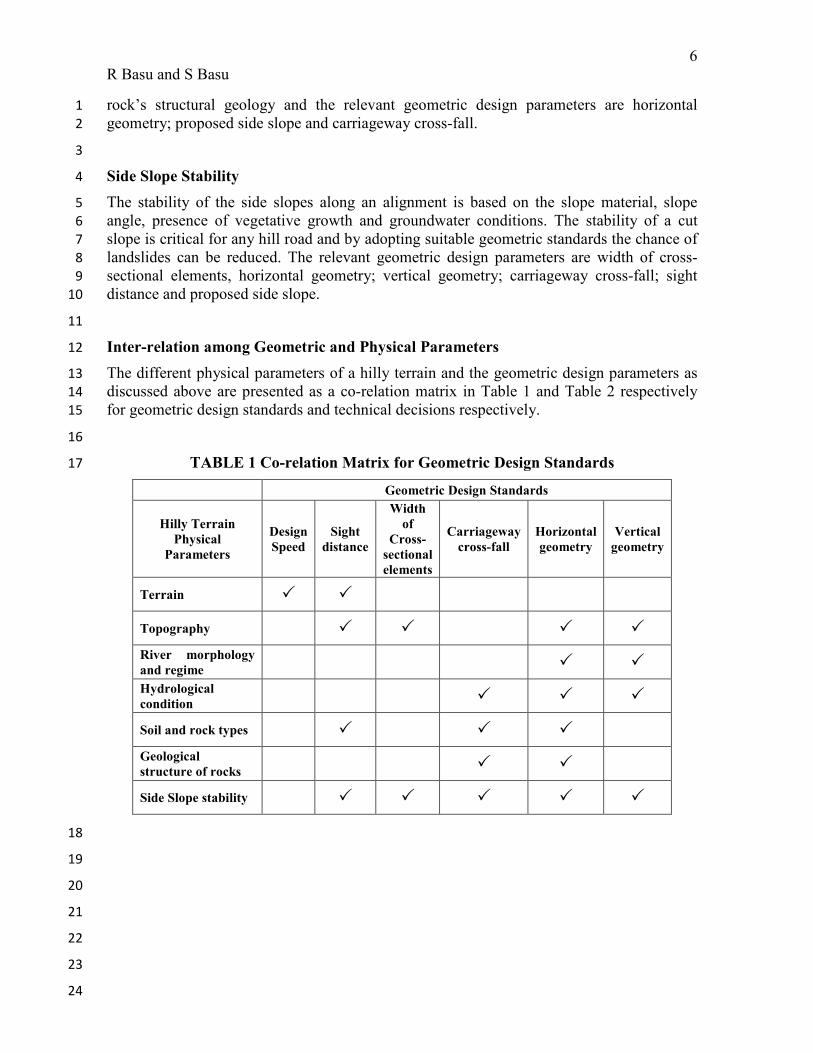
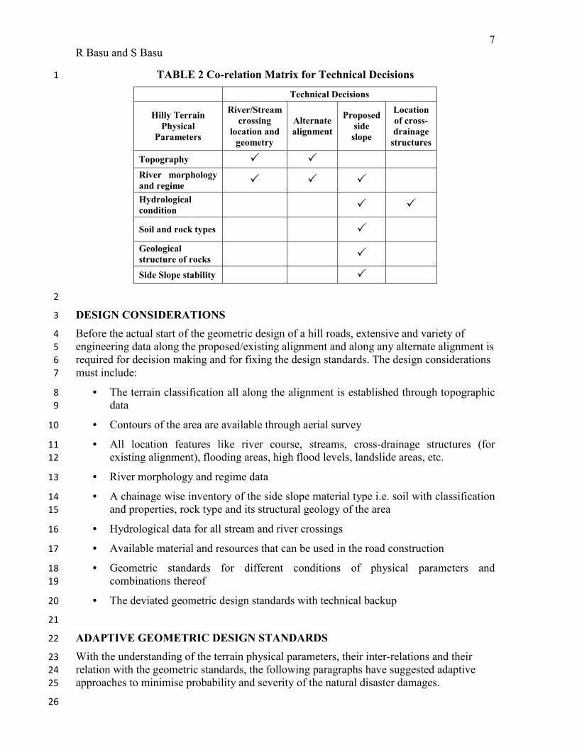
Inter-relation among Geometric and Physical Parameters 12
The different physical parameters of a hilly terrain and the geometric design parameters as 13
discussed above are presented as a co-relation matrix in Table 1 and Table 2 respectively 14
for geometric design standards and technical decisions respectively. 15
16
TABLE 1 Co-relation Matrix for Geometric Design Standards 17
Geometric Design Standards
Hilly Terrain
Physical
Parameters
Design
Speed
Sight
distance
Width
of
Cross-
sectional
elements
Carriageway
cross-fall
Horizontal
geometry
Vertical
geometry
Terrain � �
Topography � � � �
River morphology
and regime � �
Hydrological
condition � � �
Soil and rock types � � �
Geological
structure of rocks
� �
Side Slope stability � � � � �
18
19
20
21
22
23
24
7
R Basu and S Basu
TABLE 2 Co-relation Matrix for Technical Decisions 1
Technical Decisions
Hilly Terrain
Physical
Parameters
River/Stream
crossing
location and
geometry
Alternate
alignment
Proposed
side
slope
Location
of cross-
drainage
structures
Topography � �
River morphology
and regime � � �
Hydrological
condition � �
Soil and rock types �
Geological
structure of rocks �
Side Slope stability �
2
DESIGN CONSIDERATIONS 3
Before the actual start of the geometric design of a hill roads, extensive and variety of 4
engineering data along the proposed/existing alignment and along any alternate alignment is 5
required for decision making and for fixing the design standards. The design considerations 6
must include: 7
• The terrain classification all along the alignment is established through topographic 8
data 9
• Contours of the area are available through aerial survey 10
• All location features like river course, streams, cross-drainage structures (for 11
existing alignment), flooding areas, high flood levels, landslide areas, etc. 12
• River morphology and regime data 13
• A chainage wise inventory of the side slope material type i.e. soil with classification 14
and properties, rock type and its structural geology of the area 15
• Hydrological data for all stream and river crossings 16
• Available material and resources that can be used in the road construction 17
• Geometric standards for different conditions of physical parameters and 18
combinations thereof 19
• The deviated geometric design standards with technical backup 20
21
ADAPTIVE GEOMETRIC DESIGN STANDARDS 22
With the understanding of the terrain physical parameters, their inter-relations and their 23
relation with the geometric standards, the following paragraphs have suggested adaptive 24
approaches to minimise probability and severity of the natural disaster damages. 25
26
8
R Basu and S Basu
1
2
Design Speed 3
As per IRC guidelines, design speeds are based on the terrain classification and category of 4
road with a difference of 10 km/hr between the ruling and minimum speeds of same terrain 5
condition. The difference between ruling speed in mountainous terrain and minimum speed 6
for steep terrain in same category of road is 20 km/hr. The ruling minimum and absolute 7
minimum horizontal curve radii are also based on these speeds. A hill road may have 8
intermittent mountainous and steep terrain conditions. In such cases, recommendation of 9
code suggests to adopt a uniform terrain over a significant length. No limiting length is 10
specified for adopting a particular terrain. As per the provisions in IRC codes, the designers 11
have to decide a suitable terrain based on judgement and available data. While deciding the 12
design speed over a stretch the intermittent terrains are thus ignored. This result in high cut 13
fill heights at those isolated stretches and may create unstable cut fill slopes. 14
In most practical situations, it is observed that the design speed cannot be 15
maintained over a stretch and a speed envelop of 10 km/hr is not enough to cover such 16
differences. It is suggested to provide a design speed envelop of 20 km/hr for stretches 17
where intermittent mountainous and steep terrains exist and so the design speed can be 18
suitably decided by the designer. Apart from reducing the impact on the hill slopes, the 19
safety and operational aspects also need to be evaluated while adopting a design speed 20
value. 21
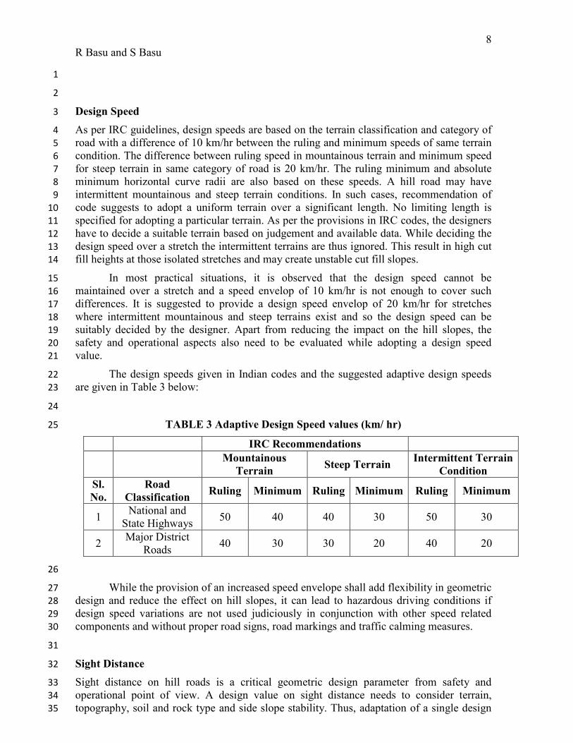
The design speeds given in Indian codes and the suggested adaptive design speeds 22
are given in Table 3 below: 23
24
TABLE 3 Adaptive Design Speed values (km/ hr) 25
IRC Recommendations
Mountainous
Terrain Steep Terrain
Intermittent Terrain
Condition
Sl.
No.
Road
Classification Ruling Minimum Ruling Minimum Ruling Minimum
1 National and
State Highways 50 40 40 30 50 30
2 Major District
Roads 40 30 30 20 40 20
26
While the provision of an increased speed envelope shall add flexibility in geometric 27
design and reduce the effect on hill slopes, it can lead to hazardous driving conditions if 28
design speed variations are not used judiciously in conjunction with other speed related 29
components and without proper road signs, road markings and traffic calming measures. 30
31
Sight Distance 32
Sight distance on hill roads is a critical geometric design parameter from safety and 33
operational point of view. A design value on sight distance needs to consider terrain, 34
topography, soil and rock type and side slope stability. Thus, adaptation of a single design 35
9
R Basu and S Basu
standard value may result in high cut heights for steep and unstable side slopes and thus 1
makes slopes susceptible to damages during natural disasters. 2
The set-back distance at a horizontal curve is recommended based on the sight 3
distance and sight distance is based on design speed. So, when a design speed is fixed the 4
set back is also fixed for any hill side slope and material condition. In an adaptive approach, 5
the design speed at such locations can be reduced to reduce the requirement of sight 6
distance and set-back distance. 7
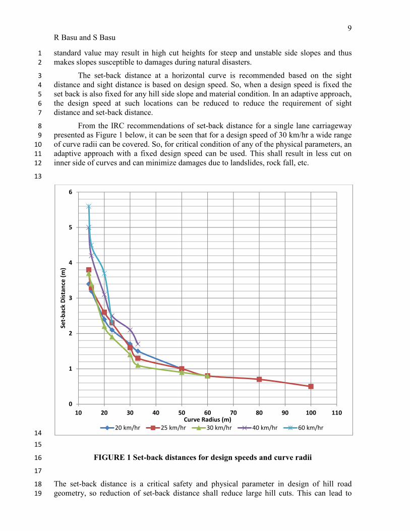
From the IRC recommendations of set-back distance for a single lane carriageway 8
presented as Figure 1 below, it can be seen that for a design speed of 30 km/hr a wide range 9
of curve radii can be covered. So, for critical condition of any of the physical parameters, an 10
adaptive approach with a fixed design speed can be used. This shall result in less cut on 11
inner side of curves and can minimize damages due to landslides, rock fall, etc. 12
13
14
15
FIGURE 1 Set-back distances for design speeds and curve radii 16
17
The set-back distance is a critical safety and physical parameter in design of hill road 18
geometry, so reduction of set-back distance shall reduce large hill cuts. This can lead to 19
0
1
2
3
4
5
6
10 20 30 40 50 60 70 80 90 100 110
Se
t-b
ack
Dis
tan
ce (
m)
Curve Radius (m)
20 km/hr 25 km/hr 30 km/hr 40 km/hr 60 km/hr
10
R Basu and S Basu
safety concerns, if such reduced set-back distances are not proposed in conjunction with 1
reduced design speeds or through traffic calming measures. 2
3
Width of Cross-sectional Elements 4
The widths of the cross-sectional elements of a hill road are fixed at the planning stage 5
based on the category of road and capacity requirements. The carriageway width being 6
considered as fixed over the entire length of a road, the only variable is the shoulder widths 7
and the total roadway width which exclude the roadside drains (usually 0.6 m) and parapet 8
walls (usually 0.6 m). For National and State Highways the carriageway width is 7.0m with 9
0.9m shoulder on both sides, i.e. total roadway width is 8.80 m (8). The total roadway width 10
was revised to 10.0m excluding drain and parapet (10). The shoulder widths has been 11
stipulated as 1.0m on hill side and 2.0 m of valley side for both mountainous and steep 12
terrains, carriageway being kept same at 7.0 m (10). 13
The topography along the alignment needs to be considered while adopting the 14
widths of shoulder on hill and valley sides. Though, operational benefits have been 15
achieved by providing a wider roadway by 1.20 m, but the same has resulted in higher cut 16
heights. As in most of the cases, the new codal stipulations are enforced during 17
rehabilitation / upgradation of a road, the extra width of 1.20m is achieved by cutting the 18
hill side without disturbing the valley side parapet walls. This sometimes makes the side 19
slopes unstable and vulnerable to damages during natural disasters. 20
By adopting a rational approach, a location specific engineering decision on whether 21
to keep the roadway of 8.80m or widen it to 10.0m should be made, so as not to disturb the 22
critical slope locations. 23
While some hill cut may be avoided by change of the shoulder widths, but uniform 24
widths of shoulder is desirable for safe driving condition and to avoid change of driver 25
perceptions on edge shyness. 26
27
Carriageway Cross-fall 28
Carriageway cross-fall plays a vital road in road surface drainage, pavement layer drainage 29
as well as groundwater movement across the road. Generally, IRC stipulates bi-directional 30
cross-fall of 2.5% with crown at the middle for bituminous surfaces (8). Alternately, it 31
recommends a uni-directional cross-fall towards the hill side (in-sloped with ditches) for 32
winding alignment stretches only. 33
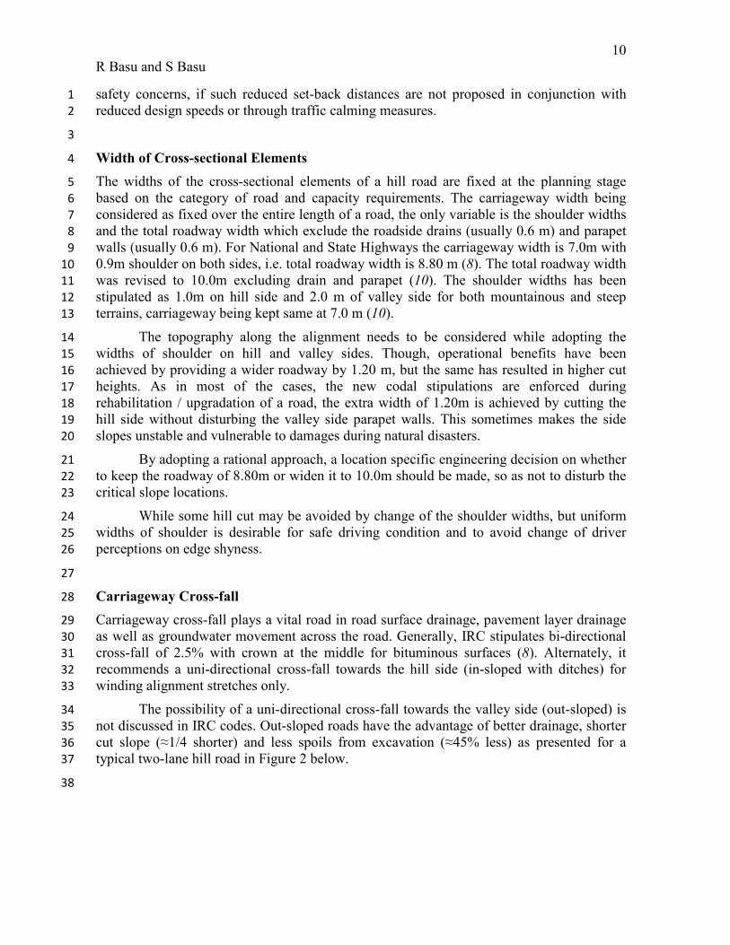
The possibility of a uni-directional cross-fall towards the valley side (out-sloped) is 34
not discussed in IRC codes. Out-sloped roads have the advantage of better drainage, shorter 35
cut slope (≈1/4 shorter) and less spoils from excavation (≈45% less) as presented for a 36
typical two-lane hill road in Figure 2 below. 37
38
11
R Basu and S Basu
1
2
FIGURE 2 Comparison of In-sloped and Out-sloped Road 3
4
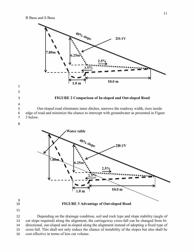
Out-sloped road eliminates inner ditches, narrows the roadway width, rises inside 5
edge of road and minimize the chance to intercept with groundwater as presented in Figure 6
3 below. 7
8
9 FIGURE 3 Advantage of Out-sloped Road 10
11
Depending on the drainage condition, soil and rock type and slope stability (angle of 12
cut slope required) along the alignment, the carriageway cross-fall can be changed from bi-13
directional, out-sloped and in-sloped along the alignment instead of adopting a fixed type of 14
cross-fall. This shall not only reduce the chance of instability of the slopes but also shall be 15
cost effective in terms of less cut volume. 16
12
R Basu and S Basu
The dip angle of a rock slope is an important factor which decides the stability of a 1
rock slope. At locations where the dip is such that the bedding planes are inclined towards 2
the face of the slope, the chances of instability are more. The carriageway cross-fall, 3
proposed side slope angle and the roadway formation cut slope of the road can be decided 4
such as to decrease the stress on the underlying rock bed. 5
The disadvantage of an out-sloped road is that the road surface water shall flow 6
towards the valley side, thus increasing the probability of rain cuts if proper slope protection 7
and drainage system is not adopted. So, a decision need to be taken considering the 8
suitability of valley side slope protection measures. 9
10
Horizontal Geometry 11
The horizontal geometry of a hill road is proposed and selected after alternate alignment 12
study. If during the alternate alignment selection, the critical ground conditions are 13
considered at a more detail level, the road alignment shall have fewer chances of damages 14
during natural disasters. In case the road corridor is fixed, the actual geometry of the road is 15
designed based on the design standards adopted. Designing the horizontal geometry by 16
strict adherence of standards may result in high cut-fill heights, unstable cut slopes, 17
proximity of river course, etc. All these make the road susceptible to damages during 18
natural disasters. Sometimes minor deviation from the selected corridor can avoid some of 19
the critical locations. 20
21
The horizontal alignment of a hill road need to be adaptive by : 22
• Aligning road where ground slopes are within 10% - 40% for gentle road gradients, 23
better drainage and less cut fill quantities 24
• Introduction of matching horizontal curves based on ground topography (matching 25
contours as much as possible) to result in less disturbance of the natural slopes 26
• Maintaining sufficient distance from the river course and any possible future change 27
of course to avoid lateral erosion by stream undercutting and minimize crossing of 28
tributary streams 29
• Minimizing or avoiding multiple river crossing by keeping alignment on one side of 30
the river 31
• Avoiding any surface flow areas and minimizing stream crossing shall ensure a dry 32
road pavement 33
• Avoiding areas with loose soil and fragmented rock types which if disturbed can be 34
prone to landslides and rock fall 35
• Avoiding areas with unfavourable dips of rock surface to avoid the damage due to 36
movement of rock faults 37
• Avoiding active landslide and rock fall areas 38
39
As all the above critical physical conditions on a hill road alignment may not be 40
possible to avoid by one single horizontal and vertical alignment, so the designer need to 41

13
R Basu and S Basu
consider all options to propose best solution which minimize the disturbance of natural 1
conditions and surrounding habitats. 2
3
Vertical Geometry 4
Best hill road alignment is a combination of well-fitted horizontal and vertical geometry, 5
which would result in balanced cut-fill and have minimum adverse effect on the 6
surrounding ground. Thus, vertical geometry plays an equal important role and can 7
minimize the damages if designed considering the critical physical parameters of the 8
ground. Design of vertical geometry by adherence of standards may result in high vertical 9
grades, disturbance of the groundwater table, change of watercourse of small streams, etc. 10
All such locations can become more susceptible to damages during natural disasters. 11
The vertical alignment of a hill road need to be adaptive by: 12
• Adopting mild vertical grades for reduced potential for erosion of road bed, 13
avoidance of stream diversion at stream crossings and allowing road surface to drain 14
down slope 15
• Designing vertical profile compatible with natural topography for optimum and 16
balanced cut-fill quantities hence generate less spoil 17
• Keeping finished road level and fill slopes higher than the high flood level (HFL) 18
which is ascertained for rare occurrences of change of river regime also (mainly in 19
case of strategically important roads) 20
• Avoiding interception with water table line which cause wet pavement layers 21
• Optimizing the cut height at landslide and rock fall prone areas 22
23
As all the above critical physical conditions on a hill road alignment may not be 24
possible to avoid by one single horizontal and vertical alignment, so the designer need to 25
consider all options to propose best solution which minimize the disturbance of natural 26
conditions and surrounding habitats. 27
28
ADAPTIVE TECHNICAL DECISIONS 29
During the project inception stage and feasibility stage, the designers study the various 30
varying technical parameters of the terrain along the alternate corridors. The technical 31
decisions like river/stream crossing locations and geometry, alternate alignment for existing 32
roads through landslide prone/unstable areas, proposed side slope/protection and location of 33
cross-drainage structures are taken at the inception and feasibility stages. 34
A dynamic approach to select the best alternative alignment should be taken 35
considering all the aspects rather than based on single most critical criteria. The alternative 36
solution chosen without proper analysis may result in a solution which is more susceptible 37
to damage during natural calamities than the existing road when evaluated over a longer 38
time period. 39
A matrix and ranking approach may be adopted for the specific location which shall 40
evaluate each of the locations/solutions/alignments with the pros and cons for each of the 41
physical parameters individually and then as combinations. A typical ranking format for a 42
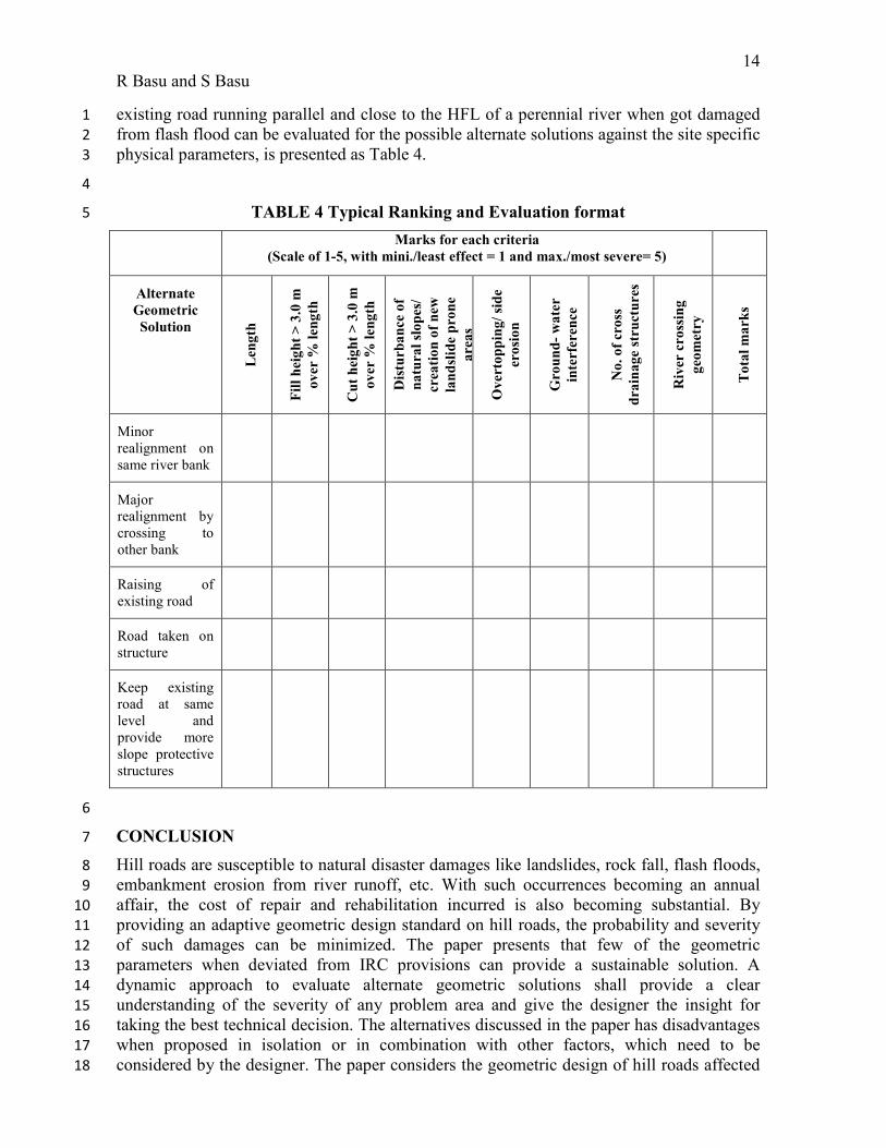
14
R Basu and S Basu
existing road running parallel and close to the HFL of a perennial river when got damaged 1
from flash flood can be evaluated for the possible alternate solutions against the site specific 2
physical parameters, is presented as Table 4. 3
4
TABLE 4 Typical Ranking and Evaluation format 5
Marks for each criteria
(Scale of 1-5, with mini./least effect = 1 and max./most severe= 5)
Alternate
Geometric
Solution
Len
gth
Fil
l h
eig
ht
> 3
.0 m
ov
er %
len
gth
Cu
t h
eig
ht
> 3
.0 m
ov
er %
len
gth
Dis
turb
an
ce o
f
na
tura
l sl
op
es/
crea
tio
n o
f n
ew
lan
dsl
ide
pro
ne
are
as
Ov
erto
pp
ing
/ si
de
ero
sio
n
Gro
un
d-
wa
ter
inte
rfer
ence
No
. o
f cr
oss
dra
ina
ge
stru
ctu
res
Riv
er c
ross
ing
geo
met
ry
To
tal
ma
rks
Minor
realignment on
same river bank
Major
realignment by
crossing to
other bank
Raising of
existing road
Road taken on
structure
Keep existing
road at same
level and
provide more
slope protective
structures
6
CONCLUSION 7
Hill roads are susceptible to natural disaster damages like landslides, rock fall, flash floods, 8
embankment erosion from river runoff, etc. With such occurrences becoming an annual 9
affair, the cost of repair and rehabilitation incurred is also becoming substantial. By 10
providing an adaptive geometric design standard on hill roads, the probability and severity 11
of such damages can be minimized. The paper presents that few of the geometric 12
parameters when deviated from IRC provisions can provide a sustainable solution. A 13
dynamic approach to evaluate alternate geometric solutions shall provide a clear 14
understanding of the severity of any problem area and give the designer the insight for 15
taking the best technical decision. The alternatives discussed in the paper has disadvantages 16
when proposed in isolation or in combination with other factors, which need to be 17
considered by the designer. The paper considers the geometric design of hill roads affected 18
15
R Basu and S Basu
by heavy rainfall during monsoon. Further study can be carried out in same direction for hill 1
roads in snow clad areas. 2
3
4
References 5
6
1. National Highways Authority of India (NHAI), Road Network. 7
http://www.nhai.org/roadnetwork.htm. Accessed Oct. 10, 2014. 8
2. National Disaster Management Authority, Govt. of India, Vulnerability Profile. 9
http://www.ndma.gov.in/en/vulnerability-profile.html. Accessed Oct. 10, 2014 10
3. Sidle, R. C. & Ochiai, H. Landslides: Processes, Prediction and Land Use Water 11
Resources Monogr. 18 (Am. Geophys. Union, 2006). 12
4. Sidle R. C. et al. Erosion processes in steep terrain—Truths, myths, and 13
uncertainties related to forest management in Southeast Asia, Forest Ecol. Manag. 224, 14
199–225 (2006). 15
5. Sidle, R. C., Furuichi, T. & Kono, Y., Unprecedented rates of landslide and 16
surface erosion along a newly constructed road in Yunnan, China Nat. Hazards 57, 313–326 17
(2011). 18
6. Hearn. G.J., Engineering geomorphology for road design in unstable 19
mountainous areas: lessons learnt after 25 years in Nepal, Quart. J. of Eng. Geology and 20
Hydrogeology, 35 no. 2, 143-154 (2002). 21
7. Armstrong. A., Reid. L., Davis. A.J., An Integrated Approach for Designing and 22
Building Sustainable Roads, Green Streets, Highways, and Development, 1-20,2 23
8. Indian Road Congress (IRC), Special Publication 48, Hill Road Manual, India (1998) 24
9. Indian Road Congress (IRC), IRC:52, Recommendations about the Alignment 25
Survey and Geometric Design of Hill Roads, India (2001) 26
10. Indian Road Congress (IRC), Special Publication 72, For Two Laning of State Highway 27
on B.O.T Basis, India (2007) 28