Embed Size (px)
Citation preview
Geometric Design to Improve Surface Drainage (including Amendment No. 1, dated February 2014 and Amendment No. 2, dated December 2014)
DN-GEO-03057 December 2013
Design Technical DN
TRANSPORT INFRASTRUCTURE IRELAND (TII) PUBLICATIONS
About TII Transport Infrastructure Ireland (TII) is responsible for managing and improving the country’s national road and light rail networks. About TII Publications TII maintains an online suite of technical publications, which is managed through the TII Publications website. The contents of TII Publications is clearly split into ‘Standards’ and ‘Technical’ documentation. All documentation for implementation on TII schemes is collectively referred to as TII Publications (Standards), and all other documentation within the system is collectively referred to as TII Publications (Technical). This system replaces the NRA Design Manual for Roads and Bridges (NRA DMRB) and the NRA Manual of Contract Documents for Road Works (NRA MCDRW). Document Attributes Each document within TII Publications has a range of attributes associated with it, which allows for efficient access and retrieval of the document from the website. These attributes are also contained on the inside cover of each current document, for reference. For migration of documents from the NRA and RPA to the new system, each current document was assigned with new outer front and rear covers. Apart from the covers, and inside cover pages, the documents contain the same information as previously within the NRA or RPA systems, including historical references such as those contained within NRA DMRB and NRA MCDRW. Document Attributes
TII Publication Title Geometric Design to Improve Surface Drainage (including Amendment No. 1, dated February 2014 and Amendment No. 2, dated December 2014)
TII Publication Number
DN-GEO-03057
Activity Design (DN) Document Set Technical Stream Geometry (GEO) Publication Date December 2013
Document Number
03057 Historical Reference
NRA IAN 09/13
NRA DMRB and MCDRW References For all documents that existed within the NRA DMRB or the NRA MCDRW prior to the launch of TII Publications, the NRA document reference used previously is listed above under ‘historical reference’. The TII Publication Number also shown above now supersedes this historical reference. All historical references within this document are deemed to be replaced by the TII Publication Number. For the equivalent TII Publication Number for all other historical references contained within this document, please refer to the TII Publications website.
NRA Interim Advice Note 09/13
Geometric Design to Improve Surface Drainage (including
Amendment No. 1, dated February 2014, and Amendment No. 2, dated December
2014)
December 2013
St. Martin’s House, Waterloo Road, Dublin 4 Tel: +353 1 660 2511 Fax +353 1 668 0009
Email: [email protected] Web: www.nra.ie
Summary:
This NRA Interim Advice Note (NRA IAN 09/13) describes geometric design requirements intended to ensure adequate surface drainage of carriageways, together with guidance on road surface geometric design in relation to the application of the requirements and measures that can be adopted when problems have been identified. NRA IAN 09/13 also includes an assessment procedure for calculating water film depths on pavement surfaces, including limiting criteria for water depths and drainage path lengths permissible on new roads.
Published by National Roads Authority, Dublin 2013
NRA IAN 09/13 GEOMETRIC DESIGN TO IMPROVE SURFACE DRAINAGE (including Amendment No. 1 and Amendment No. 2)
December 2013 i
VOLUME 6 ROAD GEOMETRY
SECTION 1 LINKS
PART 1
NRA IAN 09/13
GEOMETRIC DESIGN TO IMPROVE SURFACE DRAINAGE (Including Amendment No. 1, dated February 2014)
Contents
1. Introduction
2. Amendments to NRA TD 9
3. New NRA TD 9 Chapter 12 Geometric Design to Improve Surface Drainage of Carriageways
4. Amendments to NRA Addendum to HD 33
5. References
Amendment No. 1
Amendment No. 2
APPENDIX A: Worked Example
NRA IAN 09/13 GEOMETRIC DESIGN TO IMPROVE SURFACE DRAINAGE (including Amendment No. 1 and Amendment No. 2)
December 2013 1
1. INTRODUCTION 1.1 This Interim Advice Note has been prepared to describe the mandatory design requirements that
shall be implemented by the designer to ensure adequate surface drainage of carriageways, in the case of new build construction1. Guidance on road surface geometric design is included within this document to provide advice on how these new requirements should2 be applied and measures that can be adopted when problems have been identified.
1.2 An assessment procedure for calculating water film depths on pavement surfaces is described herein, with limiting criteria for water depths and drainage path lengths permissible on new roads included. The contributory factors to aquaplaning are discussed and appropriate remediation measures for surface drainage problems at superelevation rollover locations are outlined.
1.3 This Interim Advice Note introduces new mandatory requirements for geometric design including an increased minimum resultant gradient allowable on the road pavement on National Roads.
This Interim Advice Note shall be read in conjunction with NRA TD 9 Road Link Design and the NRA addendum to HD 33 Surface and Subsurface Drainage Systems for Highways.
Scope
1.4 This Interim Advice Note is applicable to the design of all National Roads. Particular attention should be given to geometric design undertaken on wide carriageways such as Dual Carriageways and Motorways and at changes in superelevation.
Implementation
1.5 This Interim Advice Note shall be used for the design of all new National Roads. The principles outlined are also applicable to projects involving the renewal, reconstruction or widening of national roads and to the assessment of surface drainage on existing carriageways. However, given that it will not be generally feasible to significantly alter longitudinal and transverse gradients on existing roads to meet the design criteria set out in this Interim Advice Note, the alternative methods set out in sections 3.36 to 3.43 of this advice note should be considered. Accordingly, in situations other than the design of new roads where the alignment is generally unrestrained, the design criteria set out should be viewed as guidance and not as mandatory requirements3.
1.6 Moreover, in the case of projects that have been designed and have received approval from An Bord Pleanála prior to the adoption of this Interim Advice Note, and which accordingly have defined geometries and land-take lines that cannot be altered, for such projects the alternative methods set out in sections 3.36 to 3.43 of this advice note should be considered4.
1 Amended as per Amendment No. 2, item 1 2 Amended as per Amendment No. 2, item 2 3 Amended as per Amendment No. 2, item 3 4 Amended as per Amendment No. 2, item 4
NRA IAN 09/13 GEOMETRIC DESIGN TO IMPROVE SURFACE DRAINAGE (including Amendment No. 1 and Amendment No. 2)
December 2013 2
2. AMENDMENTS TO NRA TD 9 Appearance and Drainage
2.1 Page 3/2, Paragraph 3.7, delete entire paragraph:
Replace with:
Length of Superelevation Development
The length required for superelevation application shall be sufficient5 to ensure satisfactory driver comfort and a good visual appearance. Higher design speeds and wider carriageways will necessitate longer application lengths to meet these criteria; however the influence of rollover application on surface drainage conditions must be taken into account. If superelevation is applied so gradually as to create large almost flat areas of road pavement, storm water runoff will build up on the carriageway surface and increase the potential for aquaplaning. Therefore, in certain circumstances, the design length of superelevation development must balance the need for comfort and appearance without compromising surface drainage.
A satisfactory appearance can usually be achieved by ensuring that the road pavement edge profile does not vary in grade by more than 1% from that of the line about which the carriageway is pivoted, i.e. axis of rotation.
On Motorways and Dual Carriageways, a smoother edge profile shall be provided by reducing the variation in grade of the edge profile to a maximum of 0.5% with ample smoothing of all6 changes in edge profile.
It should be stressed that these guidelines represent the ideal scenario in considering both driver comfort and visual appearance, but are unlikely to be achievable where longitudinal gradients are low and surface drainage problematic. Where there is a need to manage the flow paths of storm water runoff, the variation in grade of the edge profile should be progressively increased and a linear application of superelevation adopted. However, the relative gradient between the pavement edge and axis of rotation must not be increased beyond a maximum value of 1% to ensure driver comfort is not unduly compromised.
Areas susceptible to drainage problems shall be identified at an early stage in the design process, before the alignment is fixed. Once the alignment is fixed, rollover areas shall be checked by triangulation of three dimensional road models to ensure that no point on the road pavement has a gradient of less than 1%. This represents the net resultant gradient taking into account carriageway crossfall and longitudinal gradient.
5 Amended as per Amendment No. 2, item 5 6 Amended as per Amendment No. 1, item 1
NRA IAN 09/13 GEOMETRIC DESIGN TO IMPROVE SURFACE DRAINAGE (including Amendment No. 1 and Amendment No. 2)
December 2013 3
3. NEW NRA TD 9 CHAPTER 12 GEOMETRIC DESIGN TO IMPROVE SURFACE DRAINAGE OF CARRIAGEWAYS
Effects of Surface Water on the Carriageway
Aquaplaning
3.1 For a tyre to grip a wet road, it is necessary for surface water to be displaced from the tyre contact patch to ensure the tread can make intimate contact with the road surface. The provision of appropriate road drainage in conjunction with suitable transverse crossfalls and longitudinal pavement gradients will ensure that there is a minimal depth of water on the road surface. The degree to which water is displaced is largely governed by the speed of the vehicle, and the capacity of the pavement macrotexture and tyre tread grooves to provide the necessary drainage paths. If the combination of water depth on the road surface, vehicle speed and tyre condition exceeds the point where the tyre tread and surface texture can disperse it, the thickness of the water film in front of the tyre will build up and begin to penetrate the contact patch.
3.2 Aquaplaning occurs when the vehicle’s tyres are partially or fully separated from the road surface by a film of water which results in loss of control of the vehicle. Full aquaplaning is unlikely to occur when vehicles operate within the speed limits with tyres maintained and in good condition. Partial aquaplaning is more likely to occur resulting in loss of control during wet conditions when any of the above parameters are not being met.
3.3 Aquaplaning potential can be assessed from the following two stage process:
i) Determine the expected water film depth for a given flow path across the carriageway;
ii) Check estimated water depths against acceptable design limits.
3.4 It should be noted that although the assessment process concentrates on the prediction of surface water depths, road collisions are typically complex, multi-factored incidents that usually cannot be attributed to one single cause. Therefore, a reduction in skid resistance arising from wet weather conditions may be a contributory factor but it would not necessarily be the only causal factor in road accidents. Other factors such as driver behaviour, vehicle condition, road geometry and climatic conditions, including extreme rainfall events, may be involved to varying degrees.
Aquaplaning versus Skidding
3.5 It is important to appreciate that while aquaplaning arises from a loss of skid resistance due to a reduced or absent contact patch between tyre and pavement, skidding occurs with no separation between tyre and road. Skidding typically occurs as a consequence of vehicle manoeuvres involving excessive acceleration or braking; generally experienced on bends, on the approaches to, and at junctions. A partial aquaplaning incident is essentially a combination of aquaplaning and skidding.
NRA IAN 09/13 GEOMETRIC DESIGN TO IMPROVE SURFACE DRAINAGE (including Amendment No. 1 and Amendment No. 2)
December 2013 4
Contributory Factors
3.6 It is important for the designer to gain an appreciation for the factors influencing the occurrence of aquaplaning and in doing so, recognise that only certain factors are within the designer’s control. Key contributory factors to aquaplaning are:
iii) Road geometry;
iv) Drainage design and maintenance regimes;
v) Surface characteristics;
vi) Design / Operating speed;
vii) Rainfall intensity;
viii) Water film depth;
ix) Vehicle characteristics (tyre tread depth, tyre pressure etc.); and
x) Driver behaviour.
3.7 Rainfall intensity, driver behaviour and poor vehicle maintenance (inadequate tyre tread depth or pressure etc.) represent significant influences that are beyond the designer’s control and are indicative of the difficulty in defining strict rules for design.
3.8 Effective carriageway drainage in conjunction with applied geometric parameters is critical to ensure the expeditious removal of surface water runoff during and after a rainfall event. This is very important where there are changes in road cross section from camber (normal crossfall) to superelevation, particularly when combined with a flat longitudinal gradient. Efficient drainage systems will assist in ensuring that only a minimal quantity of water will need to be displaced at the interface between the road surface and the vehicle tyre. It is imperative that maintenance regimes are put in place in order to ensure that the removal of water from the road surface is not hindered as a result of blocked gullies, build-up of debris or verge grass growth. This is of particular importance at changes in superelevation where carriageway crossfall is low. Further guidance is contained in the NRA addendum to HD 33.
Drainage Flow Path
3.9 Runoff accumulating on the road surface will tend to follow the path of steepest gradient to the carriageway edge. The flow path is the route taken by rainfall runoff from the point at which it falls on the carriageway surface to the carriageway edge. This flow path route is dictated by the combination of longitudinal gradient and crossfall, which in turn will vary depending on the horizontal and vertical geometry of the road. On straight alignments, crossfall is typically applied to fall in both directions from the centre of the road. Consequently, for a carriageway with minimal longitudinal gradient, flow path lengths are predominantly influenced by crossfall, resulting in short drainage paths and the expeditious removal of surface water.
NRA IAN 09/13 GEOMETRIC DESIGN TO IMPROVE SURFACE DRAINAGE (including Amendment No. 1 and Amendment No. 2)
December 2013 5
3.10 As longitudinal gradients increase, the length of the drainage flow path can increase significantly as the resultant fall on the carriageway becomes more influenced by the longitudinal grade than the crossfall. Although the rate of increase in water depth is partly offset by the increasing gradient, longer drainage paths will produce greater water depths which in turn will increase the risk of aquaplaning. While flow path lengths and gradients can be easily determined on sections of consistent route geometry, any areas of varying width and geometry will require careful consideration by the designer. On the approach to horizontal curves, the standard two way crossfall may transition to a one way crossfall (superelevation) giving rise to localised low crossfalls and a rapid increase in flow path lengths. The determination of drainage path lengths at superelevation rollovers is most effectively assessed by the designer using contoured plans of the carriageway surface.
Minimum Design Gradients
3.11 Most roads are designed to maintain a minimum longitudinal gradient of 0.5% wherever possible to allow for adequate water flow along the roadside edge channel. It should be noted however that on wider carriageways, the most direct drainage flow path, and therefore the shortest flow path lengths occur at zero longitudinal gradient. Low longitudinal gradients can therefore be acceptable (and potentially more effective in removing surface water) provided that standard crossfalls are maintained and a continuous drainage system utilised in accordance with the NRA Addendum to HD 33.
3.12 In areas of superelevation development, designers should aim to increase the longitudinal gradient along the road centreline to ensure a sufficient gradient is maintained along the carriageway edge.
Length of Superelevation Development
3.13 Refer to Chapter 2 of this document for details on the length of superelevation development.
Surface Characteristics
3.14 The friction available to the driver when attempting a particular manoeuvre depends on many different factors, including the characteristics of the road surface. The skidding resistance of wet roads is significantly reduced by the lubricating action of the film of water on the road surface. Consequently, in addition to the grooved channels on the tyre, adequate pavement macrotexture is necessary to provide drainage paths for the water to escape and reduce the potential for aquaplaning. The importance of good surface macrotexture becomes increasingly critical as vehicle speeds increase. High speed and a thick film of water on the road surface will encourage a vehicle to aquaplane, but a relatively thin layer of water could be problematic if combined with low texture depth and ‘smooth’ tyres. The most significant characteristic becomes the water depth when it exceeds the mean texture depth7.
3.15 Adequate pavement surface microtexture must8 be provided by the designer to enable the tip of the aggregate to penetrate any remaining water film in order to establish direct contact between the tyre and road surface. Microtexture influences wet and dry skid resistance at all speeds, interacting with the vehicle’s tyres to generate the adhesive friction forces. The degree of
7 Amended as per Amendment No. 2, item 6 8 Amended as per Amendment No. 2, item 7
NRA IAN 09/13 GEOMETRIC DESIGN TO IMPROVE SURFACE DRAINAGE (including Amendment No. 1 and Amendment No. 2)
December 2013 6
friction provided in wet conditions is dependent on the extent to which the microtexture can penetrate the surface water film.
3.16 It should be noted that pavement surface characteristics cannot be specified to compensate for extreme rainfall events, driver speed, vehicle maintenance or deficiencies in the geometric design.
Effect of Carriageway Edge Markings
3.17 Carriageway surface drainage can be affected by continuous edge markings, particularly where raised rib markings are used.
Where continuous edge lines are used drainage gaps must be included to prevent surface water ponding and the risk of localised ice formation. The spacing of drainage gaps shall be adjusted in conjunction with the vertical gradient with a 2m maximum spacing to be provided at lower gradients and superelevation rollovers. For further guidance on dimensions and spacing of drainage gaps in road markings, refer to Chapter 7 of the Traffic Signs Manual.
Geometric Design Methodology to Improve Surface Drainage Introduction
3.18 The importance of considering drainage as a fundamental part of highway design is noted in NRA TD 9, TD 16 and the NRA addendum to HD 33. The information, assessment methodology and criteria presented in this section have been developed for geometric road designers to allow them to identify and minimise aquaplaning potential.
3.19 Consideration of surface drainage (by minimising the build-up of water on the carriageway) must be viewed by the designer as an equivalent constraint to horizontal and vertical alignment design as other elementary considerations such as sight distance and limiting curvature.
Assessment Process
3.20 The method which shall be adopted by the designer is that developed by Gallaway et. al (1979) in cooperation with the Federal Highway Administration. This method provides an empirical relationship 9between average pavement texture depth, drainage flow path length, rainfall intensity and slope of drainage path to the expected water film depth on the carriageway surface.
9 Amended as per Amendment No. 1, item 2
NRA IAN 09/13 GEOMETRIC DESIGN TO IMPROVE SURFACE DRAINAGE (including Amendment No. 1 and Amendment No. 2)
December 2013 7
The metric version of the Gallaway formula is given below:
𝐷𝐷 =0.103 × 𝑇𝑇0.11 × 𝐿𝐿0.43 × 𝐼𝐼0.59
𝑆𝑆0.42 − 𝑇𝑇
Where,
D = Water film depth above the top of pavement texture (mm)
T = Average pavement texture depth (mm)
L = Length of drainage path (m)
I = Rainfall intensity (mm/hour)
S = Slope of drainage path (%)
Average Pavement Texture Depth, T10
3.21 Average pavement texture depth is an average measure of the depth of macrotexture and is an important factor influencing skidding in wet conditions on high speed roads.
To take account of reduced average pavement texture depths due to pavement deterioration, a design check shall be carried out by the designer assuming a value of 0.4mm for the average pavement texture depth11.
Length of Drainage Path, L12
3.22 The designer shall determine the drainage path length by plotting and assessing the contours on the proposed road surface. The water depth analysis shall be carried out on the critical drainage path, i.e. the longest drainage path on the carriageway within the assessment location.
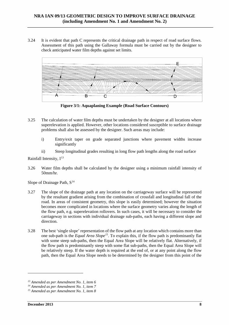
3.23 Figure 3/1 illustrates a typical example of drainage flow paths based on road surface contours at a superelevation rollover at the exit from a left hand curve.
i) Path A represents the drainage flow path when the carriageway is in full superelevation along the curve, with a constant slope applied across the full width of the road pavement.
ii) At path B, the superelevation begins to roll down on the exit from the curve resulting in a gradual change in the flow path direction and a wider contour spacing.
iii) Drainage path C is of particular interest where the flow path begins to cross the road and then, due to the superelevation rotation, returns back to the same edge of carriageway. This situation frequently results in long drainage paths with a flat section in the middle, as indicated by the wider spacing of the contours.
iv) Paths D and E represent shorter drainage paths where the carriageway has returned to a normal crossfall situation.
10 Amended as per Amendment No. 1, item 3 11 Amended as per Amendment No. 1, item 4 12 Amended as per Amendment No. 1, item 5
NRA IAN 09/13 GEOMETRIC DESIGN TO IMPROVE SURFACE DRAINAGE (including Amendment No. 1 and Amendment No. 2)
December 2013 8
3.24 It is evident that path C represents the critical drainage path in respect of road surface flows. Assessment of this path using the Gallaway formula must be carried out by the designer to check anticipated water film depths against set limits.
Figure 3/1: Aquaplaning Example (Road Surface Contours)
3.25 The calculation of water film depths must be undertaken by the designer at all locations where
superelevation is applied. However, other locations considered susceptible to surface drainage problems shall also be assessed by the designer. Such areas may include:
i) Entry/exit taper on grade separated junctions where pavement widths increase significantly
ii) Steep longitudinal grades resulting in long flow path lengths along the road surface
Rainfall Intensity, I13
3.26 Water film depths shall be calculated by the designer using a minimum rainfall intensity of 50mm/hr.
Slope of Drainage Path, S14
3.27 The slope of the drainage path at any location on the carriageway surface will be represented by the resultant gradient arising from the combination of crossfall and longitudinal fall of the road. In areas of consistent geometry, this slope is easily determined; however the situation becomes more complicated in locations where the surface geometry varies along the length of the flow path, e.g. superelevation rollovers. In such cases, it will be necessary to consider the carriageway in sections with individual drainage sub-paths, each having a different slope and direction.
3.28 The best ‘single slope’ representation of the flow path at any location which contains more than one sub-path is the Equal Area Slope15. To explain this, if the flow path is predominantly flat with some steep sub-paths, then the Equal Area Slope will be relatively flat. Alternatively, if the flow path is predominantly steep with some flat sub-paths, then the Equal Area Slope will be relatively steep. If the water depth is required at the end of, or at any point along the flow path, then the Equal Area Slope needs to be determined by the designer from this point of the
13 Amended as per Amendment No. 1, item 6 14 Amended as per Amendment No. 1, item 7 15 Amended as per Amendment No. 1, item 8
NRA IAN 09/13 GEOMETRIC DESIGN TO IMPROVE SURFACE DRAINAGE (including Amendment No. 1 and Amendment No. 2)
December 2013 9
analysis back to the start of the flow path. This value represents the value of ‘S’ in the Gallaway formula.
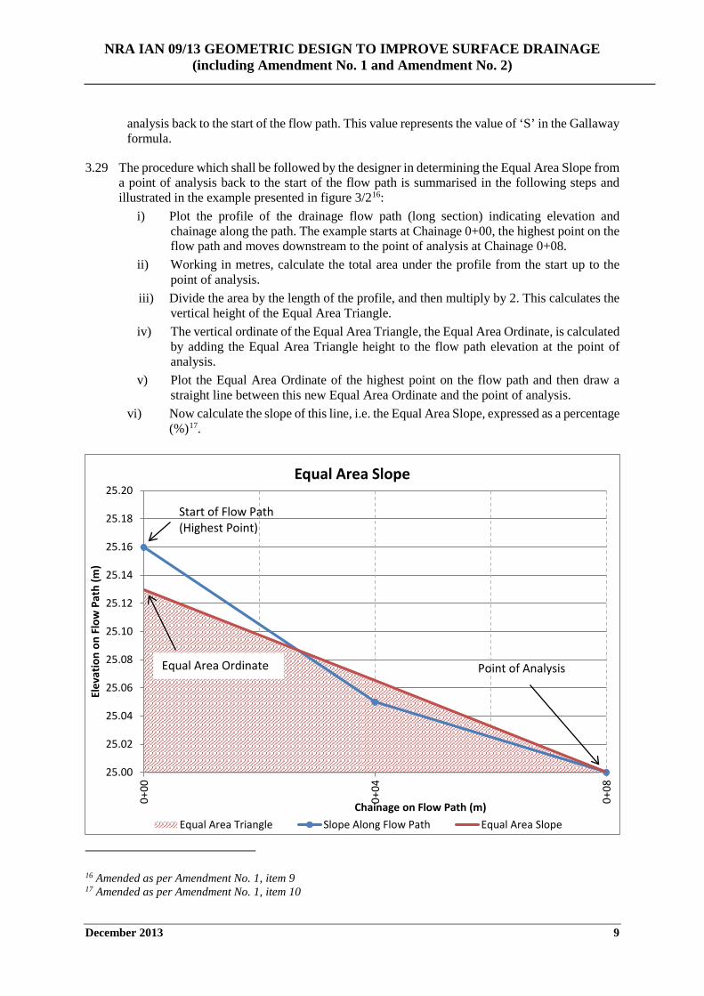
3.29 The procedure which shall be followed by the designer in determining the Equal Area Slope from a point of analysis back to the start of the flow path is summarised in the following steps and illustrated in the example presented in figure 3/216:
i) Plot the profile of the drainage flow path (long section) indicating elevation and chainage along the path. The example starts at Chainage 0+00, the highest point on the flow path and moves downstream to the point of analysis at Chainage 0+08.
ii) Working in metres, calculate the total area under the profile from the start up to the point of analysis.
iii) Divide the area by the length of the profile, and then multiply by 2. This calculates the vertical height of the Equal Area Triangle.
iv) The vertical ordinate of the Equal Area Triangle, the Equal Area Ordinate, is calculated by adding the Equal Area Triangle height to the flow path elevation at the point of analysis.
v) Plot the Equal Area Ordinate of the highest point on the flow path and then draw a straight line between this new Equal Area Ordinate and the point of analysis.
vi) Now calculate the slope of this line, i.e. the Equal Area Slope, expressed as a percentage (%)17.
16 Amended as per Amendment No. 1, item 9 17 Amended as per Amendment No. 1, item 10
25.00
25.02
25.04
25.06
25.08
25.10
25.12
25.14
25.16
25.18
25.20
0+00
0+04
0+08
Elev
atio
n on
Flo
w P
ath
(m)
Chainage on Flow Path (m)
Equal Area Slope
Equal Area Triangle Slope Along Flow Path Equal Area Slope
Equal Area Ordinate
Start of Flow Path (Highest Point)
Point of Analysis
NRA IAN 09/13 GEOMETRIC DESIGN TO IMPROVE SURFACE DRAINAGE (including Amendment No. 1 and Amendment No. 2)
December 2013 10
Figure 3/2: Equal Area Slope18
Water Film Depth Limits, D19
3.30 The following criteria shall be adopted by the designer for geometric design purposes20.
i) A maximum water film depth of 2.5mm shall apply to new single carriageway roads.
ii) On Motorways and Dual Carriageways, as the 2.5mm limit can be very difficult to achieve, a maximum value of 3.3mm shall be adopted.
iii) Road surface geometry shall be such that flow paths are limited to a length in the order of 60m21.
Where the design does not comply with these requirements, the aquaplaning potential is considered too high and a redesign will be required.
Aquaplaning Assessment Report
3.31 For new roads, the assessments carried out in accordance with the above design methodology shall be compiled by the designer in a single Aquaplaning Assessment Report for the scheme.
3.32 The Aquaplaning Assessment Report shall be submitted by email to [email protected] under the subject heading ‘NRA IAN 09/13’. Reports shall be submitted for review as part of the preliminary design process and must contain the following information as a minimum:
i) Surface contour drawings at each location assessed. This shall include all superelevation rollover locations and any other areas deemed necessary.
ii) Water film depth calculation at each assessed location in accordance with the Gallaway formula.
Guidance to Reduce Aquaplaning Potential
3.33 Where22 water film depths calculated in accordance with the Gallaway formula exceed the maximum limits, appropriate design changes23 must be implemented by the designer before the critical drainage path is reassessed. It must be recognised that while surface texture is a contributing factor to the calculated depth, drainage problems will exist irrespective of pavement texture, if the combination of crossfall and longitudinal gradient impedes the flow of surface runoff in the first instance. Avoidance of aquaplaning risk should24 be considered by the designer to be a geometric rather than a drainage issue. The shape of the road surface has the most direct influence on surface flow and the build-up of storm water runoff, which in turn directly influences the aquaplaning potential.
18 Amended as per Amendment No. 1, item 11 19 Amended as per Amendment No. 1, item 12 20 Amended as per Amendment No. 1, item 13 21 Amended as per Amendment No. 1, item 14 22 Amended as per Amendment No. 1, item 15 23 Amended as per Amendment No. 2, item 8 24 Amended as per Amendment No. 2, item 9
NRA IAN 09/13 GEOMETRIC DESIGN TO IMPROVE SURFACE DRAINAGE (including Amendment No. 1 and Amendment No. 2)
December 2013 11
3.34 If the application of the Gallaway formula results in unacceptable water film depths (see section 3.30 above), the designer must consider the following methods of adjusting the drainage flow path length or gradient to reduce the water depth in order of preference (see figure 3/3)25:
i) Alter the horizontal or vertical alignments, or both, to reduce drainage26 flow path lengths
ii) Alter the alignment to locate the rollover on a section with sufficient longitudinal gradient
iii) Adjust the rate of superelevation development or increase crossfalls to steepen drainage flow paths
iv) Consider introducing additional crown lines (diagonal or longitudinal crowns) as described in the following section if other measures are not deemed satisfactory
3.35 It is important for the designer to gain an appreciation for the interplay between longitudinal gradient and crossfall to ensure compliance with the limiting water depth criterion. Combinations of superelevation transitions with vertical curves and low gradients must be assessed by contouring the finished road surface design27 and applying the Gallaway formula. Any potential problem locations must be identified as early as possible in the design process and mitigated through amended geometric design.
Crown Lines
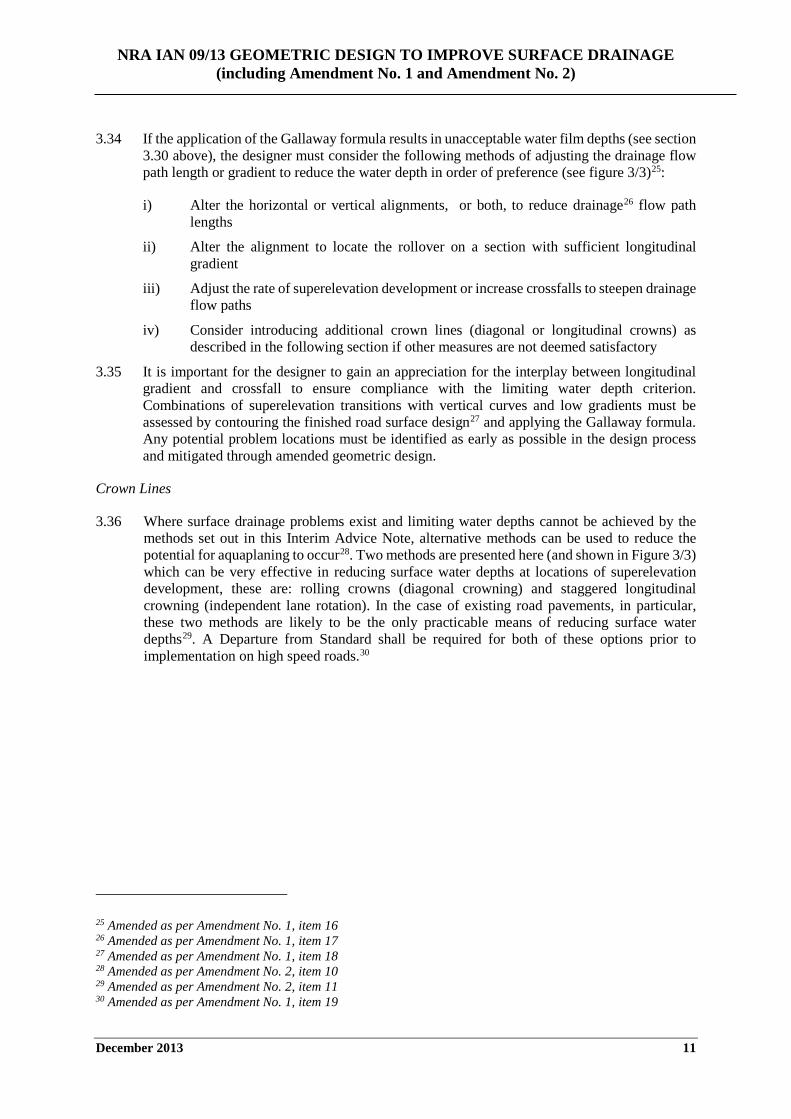
3.36 Where surface drainage problems exist and limiting water depths cannot be achieved by the methods set out in this Interim Advice Note, alternative methods can be used to reduce the potential for aquaplaning to occur28. Two methods are presented here (and shown in Figure 3/3) which can be very effective in reducing surface water depths at locations of superelevation development, these are: rolling crowns (diagonal crowning) and staggered longitudinal crowning (independent lane rotation). In the case of existing road pavements, in particular, these two methods are likely to be the only practicable means of reducing surface water depths29. A Departure from Standard shall be required for both of these options prior to implementation on high speed roads.30
25 Amended as per Amendment No. 1, item 16 26 Amended as per Amendment No. 1, item 17 27 Amended as per Amendment No. 1, item 18 28 Amended as per Amendment No. 2, item 10 29 Amended as per Amendment No. 2, item 11 30 Amended as per Amendment No. 1, item 19
NRA IAN 09/13 GEOMETRIC DESIGN TO IMPROVE SURFACE DRAINAGE (including Amendment No. 1 and Amendment No. 2)
December 2013 12
Figure 3/3: Alternative Methods of Rollover Application
Rolling Crowns
3.37 Rolling crowns provide an effective hydraulic solution to surface water problems at rollover locations by eliminating the point of zero crossfall and ensuring a crossfall is maintained at all locations along the diagonal rollover. It should be noted however that edge drainage will be required on both sides of the carriageway along the length of the crown to remove surface water (refer to the NRA addendum to HD 33 for more details).
NRA IAN 09/13 GEOMETRIC DESIGN TO IMPROVE SURFACE DRAINAGE (including Amendment No. 1 and Amendment No. 2)
December 2013 13
3.38 Rolling crowns can present difficulties in achieving the required construction tolerances, specified gradients and satisfactory ride quality. As such, the use of rolling crowns is generally not the preferred solution for new road construction. However, when used, particular care should be taken in the design, specification and construction of such features31.
3.39 Where rolling crowns are proposed for use on high speed roads, the prior approval of the National Roads Authority shall be sought via the Departures Application procedure.
3.40 Rolling crowns may be particularly suited to resolving surface drainage problems at superelevation rollovers on existing carriageways. In such cases, the use of rolling crowns may provide an effective, low cost solution to the problem with minimal impact on existing geometrics.
Rolling Crown Design
3.41 Rolling crowns can represent an abrupt change to road users on high speed roads and the effects of an instantaneous change in crossfall, particularly on heavy goods vehicles, must be considered. While the design of rolling crowns as a retrofit solution may be influenced by existing site constraints, the following guidance should32 be followed by the designer to ensure a smooth application of rollover and satisfactory ride quality.
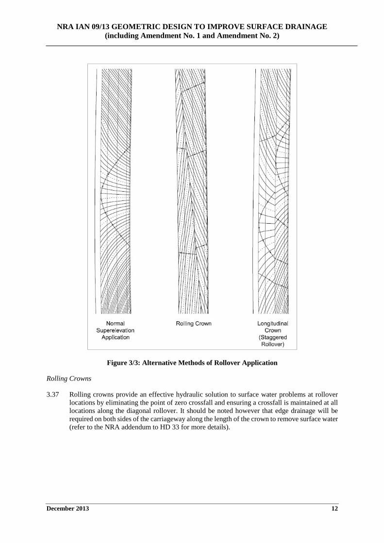
i) The pavement crossfall should33 be reduced to a maximum of 2.5% either side of the rolling crown to limit the localised change in crossfall over the crown to a maximum of 5% (see figure 3/4).
ii) The length of the diagonal crown should match the length used to apply superelevation in the normal manner. For Motorways and high speed Dual Carriageways, a crown length of about 60m per lane should be sufficient.
Figure 3/4: Application of Rolling Crown
Staggered Rollover Application (Longitudinal Crown)
3.42 Staggered rollover application or independent lane rotation can be used by the designer to apply superelevation using a longitudinal offset between adjacent lanes. The method has the benefit of reducing the overall length of superelevation development across the full width of the carriageway in comparison to normal application. It should be noted that locations of zero crossfall will still exist in each lane; however the flow path length is reduced significantly.
3.43 If staggered rollover application is proposed for use on high speed roads, the prior approval of the National Roads Authority shall be sought via the Departures Application procedure
31 Amended as per Amendment No. 2, item 12 32 Amended as per Amendment No. 2, item 13 33 Amended as per Amendment No. 2, item 14
NRA IAN 09/13 GEOMETRIC DESIGN TO IMPROVE SURFACE DRAINAGE (including Amendment No. 1 and Amendment No. 2)
December 2013 14
4. AMENDMENTS TO NRA ADDENDUM TO HD 33
Road Geometry
4.1 Page 2/1, Paragraph 2.3 Replace:
TD 9 (DMRB 6.1.1) suggests that a longitudinal gradient of 0.5% should be regarded as the minimum in these cases.
With;
TD 9 suggests that a longitudinal gradient of 1.0% should be regarded as the minimum in these cases.
4.2 Page 2/1, Paragraph 2.3 Replace:
To achieve a resultant gradient of 0.5% may require a design line gradient of 1.5%.
With;
To achieve a resultant gradient of 1.0% may require steep design line gradients.
NRA IAN 09/13 GEOMETRIC DESIGN TO IMPROVE SURFACE DRAINAGE (including Amendment No. 1 and Amendment No. 2)
December 2013 15
5. REFERENCES Austroads 2013, Guide to Road Design Part 5A Drainage – Road Surface, Networks, Basins and Subsurface, Publication No. AGRD05A-13, Austroads, Sydney, NSW, Auatralia.
Road Drainage Manual, A Guide to the Planning, Design, Operation and Maintenance of Road Drainage Infrastructure, 2nd Edition March 2010, Queensland Department of Transport, Brisbane, Australia.
Gallaway, B.M, Schiller, R.E. Jr, and Rose, J.G, May 1971 – The Effects of Rainfall Intensity, Pavement Cross Slope, Surface Texture and Drainage Length on Pavement Water Depths, Research Report 138-5, Texas Transportation Institute.
Met Éireann, D.L. Fitzgerald, Oct 2007 – Estimation of Point Rainfall Frequencies – Technical Note 61, Met Éireann, Glasnevin Hill, Dublin 9, Ireland.
NRA IAN 09/13 GEOMETRIC DESIGN TO IMPROVE SURFACE DRAINAGE (including Amendment No. 1 and Amendment No. 2)
December 2013 16
6. ENQUIRIES
6.1 All technical enquiries or comments on this document, or any of the documents listed as forming part of the NRA DMRB, should be sent by e-mail to [email protected], addressed to the following:
Head of Network Management, Engineering Standards & Research National Roads Authority St Martin’s House Waterloo Road Dublin 4
……………………………………………………...
Pat Maher Head of Network Management, Engineering Standards & Research
NRA IAN 09/13 GEOMETRIC DESIGN TO IMPROVE SURFACE DRAINAGE (including Amendment No. 1 and Amendment No. 2)
February 2014 i
National Roads Authority
Interim Advice Note (NRA IAN)
AMENDMENT No. 1 (February 2014) to NRA IAN 09/13 Geometric Design to Improve Surface Drainage
Dated December 2013 NRA IAN 09/13 Geometric Design to Improve Surface Drainage Dated December 2013 is amended as follows:- 1. Page 2, Paragraph 2.1
Delete the text ‘the’ from the second line. 2. Page 6, Paragraph 3.20
Delete the text ‘relating’ and replace with the text ‘between’ in the third line.
3. Page 6, Paragraph 3.21, Heading Add ‘, T’ to the heading.
4. Page 7, Paragraph 3.21 Add the text ‘pavement’ to the first line, and delete the text ‘surface’ and add the text ‘average pavement’ to the third line.
5. Page 7, Paragraph 3.22, Heading Add ‘, L’ to the heading.
6. Page 8, Paragraph 3.26, Heading Add ‘, I’ to the heading.
7. Page 8, Paragraph 3.27, Heading Add ‘, S’ to the heading.
8. Page 8, Paragraph 3.28 Delete the text ‘(see figure 3/2)’.
9. Page 8, Paragraph 3.29 Add the text ‘and illustrated in the example presented in figure 3/2’ in line 3.
10. Page 8, Paragraph 3.29, (numbering) • In item i) add the text ‘drainage’ in the first line, and also add the text ‘indicating elevation
and chainage along the path. The example starts at Chainage 0+00, the highest point on the flow path and moves downstream to the point of analysis at Chainage 0+08’ to the end of the first line;
• In item ii) add the text ‘from the start up to the point of analysis’ to the end of the first line;
NRA IAN 09/13 GEOMETRIC DESIGN TO IMPROVE SURFACE DRAINAGE (including Amendment No. 1 and Amendment No. 2)
February 2014 ii
• In item iii) delete the text ‘ordinate of the equal area triangle’ and add the text ‘height of the Equal Area Ordinate’ to the end of the second line.
• Add a new item iv) including the text ‘The vertical ordinate of the Equal Area Triangle, the Equal Area Ordinate, is calculated by adding the Equal Area Triangle height to the flow path elevation at the point of analysis’
11. Page 9, Figure 3/2
Delete existing chart and insert new chart
12. Page 9, Paragraph 3.30, Heading Delete ‘Assessment Criteria’ and add ‘Water Film Depth Limits, D’.
13. Page 9, Paragraph 3.30 Move the text ‘Where the design does not comply with these requirements, the aquaplaning potential is considered too high and a redesign will be required.’ to below the numbered items.
14. Page 9, Paragraph 3.30, (numbering) In item ii) add the text ‘as’, and delete the text ‘will’ and replace with the text ‘can’ both in the first line, and also delete the text ‘on Motorways and Dual Carriageways’ from the end of the item.
15. Page 10, Paragraph 3.33 Delete the text ‘If’ and add the text ‘Where’ at the start of the first line.
16. Page 10, Paragraph 3.34 Add the text ‘the’ to the first line, and add the text ‘drainage’ to the third line.
17. Page 10, Paragraph 3.34, (numbering) In item i) add the text ‘drainage’.
18. Page 10, Paragraph 3.35 Add the text ‘design’ to the fourth line.
19. Page 10, Paragraph 3.36 Add the text ‘here (and shown in Figure 3/3)’ to the fourth line, and add the text ‘A Departure from Standard shall be required for both of these options prior to implementation on high speed roads’ to the end of the paragraph.
20. Page A/1, Paragraph A.2 Delete the text ‘it is required to calculate’ and add the text ‘a calculation of’ and delete the text ‘at the end of’ and add the text ‘along’ in the first line. Also add the text ‘is required’ in the second line.
21. Page A/1, Paragraph A.3, (numbering)
• In item ii) Delete the text ‘ Surface’ add the text ‘Average pavement’ and delete the text ‘assumed conservatively as’ and add the text ‘of’;
• Add a new item v) with the text ‘A 4m distance has been adopted as the interval in this example for simplicity. An interval of 1m should be considered by the designer when carrying out a more detailed analysis’
22. Page A/1, Paragraph A.4, (numbering)
NRA IAN 09/13 GEOMETRIC DESIGN TO IMPROVE SURFACE DRAINAGE (including Amendment No. 1 and Amendment No. 2)
February 2014 iii
• In item ii) add the text ‘of the carriageway’ in the first and third lines, and add the text ‘on’ in the second line.
• In item iii) delete the text ‘will be’ and add the text ‘is’ to the first line. 23. Page A/2, Paragraph A.5
Add the text ‘from the three dimensional model’ to the first line, and delete the existing table and add a new table.
24. Page A/2, Paragraph A.6
Delete the text ‘depth’ from the first line, and delete the text ‘for the longest drainage path’ and add the text ‘at each point of analysis’ also in the first line.
25. Page A/2, Paragraph A.6
Add the text ‘average pavement’ to the first line. 26. Page A/3, Paragraph A.6
• Delete the text ‘For drainage path length L, and drainage path slope S, refer to section 3’ and add the text ‘The length of the drainage flow path, L, at the each point of analysis is given in Table A1 above’; Delete the text ‘assessment’ and add the text ‘analysis’ in the first line;
• Delete the text ‘A summary of the calculations is presented in the following table’ and also delete the existing table; and
• Add a new section of text, charts and table, as outlined here.
Application of Methodology
The calculation of water film depth must be undertaken at each interval point on the drainage flow path, to establish where on the drainage flow path the maximum water film depth exists.
For convenience and to demonstrate the procedure to be followed a point of analysis has been chosen (16m) and the Equal Area Slope is calculated at this point on the flow path. Using the values in Table A1 and the procedure described in section 3.29,
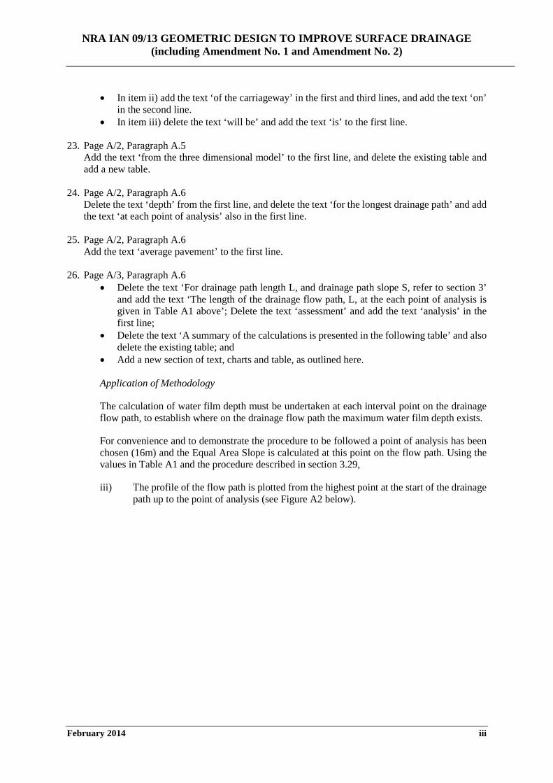
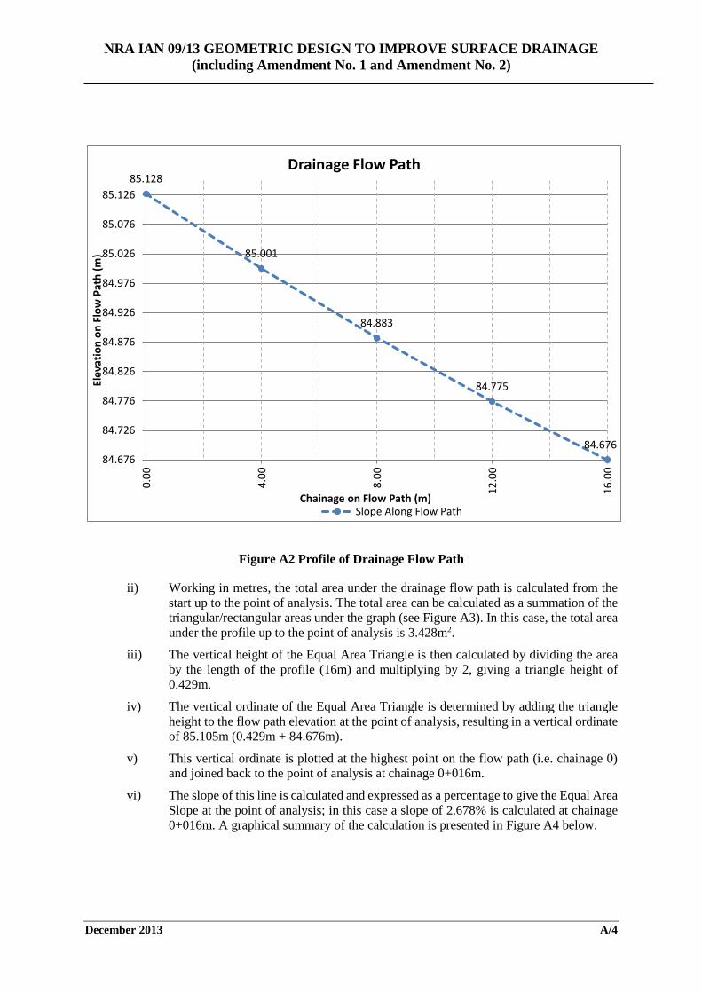
iii) The profile of the flow path is plotted from the highest point at the start of the drainage path up to the point of analysis (see Figure A2 below).
NRA IAN 09/13 GEOMETRIC DESIGN TO IMPROVE SURFACE DRAINAGE (including Amendment No. 1 and Amendment No. 2)
February 2014 iv
Figure A2 Profile of Drainage Flow Path
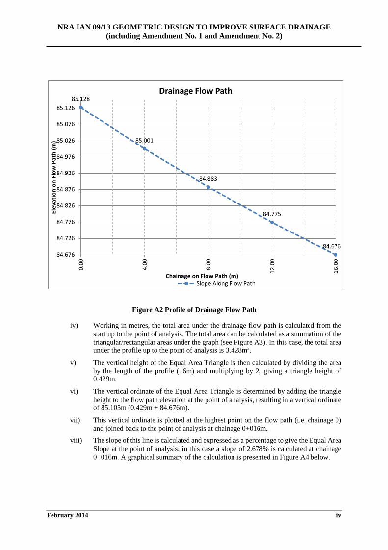
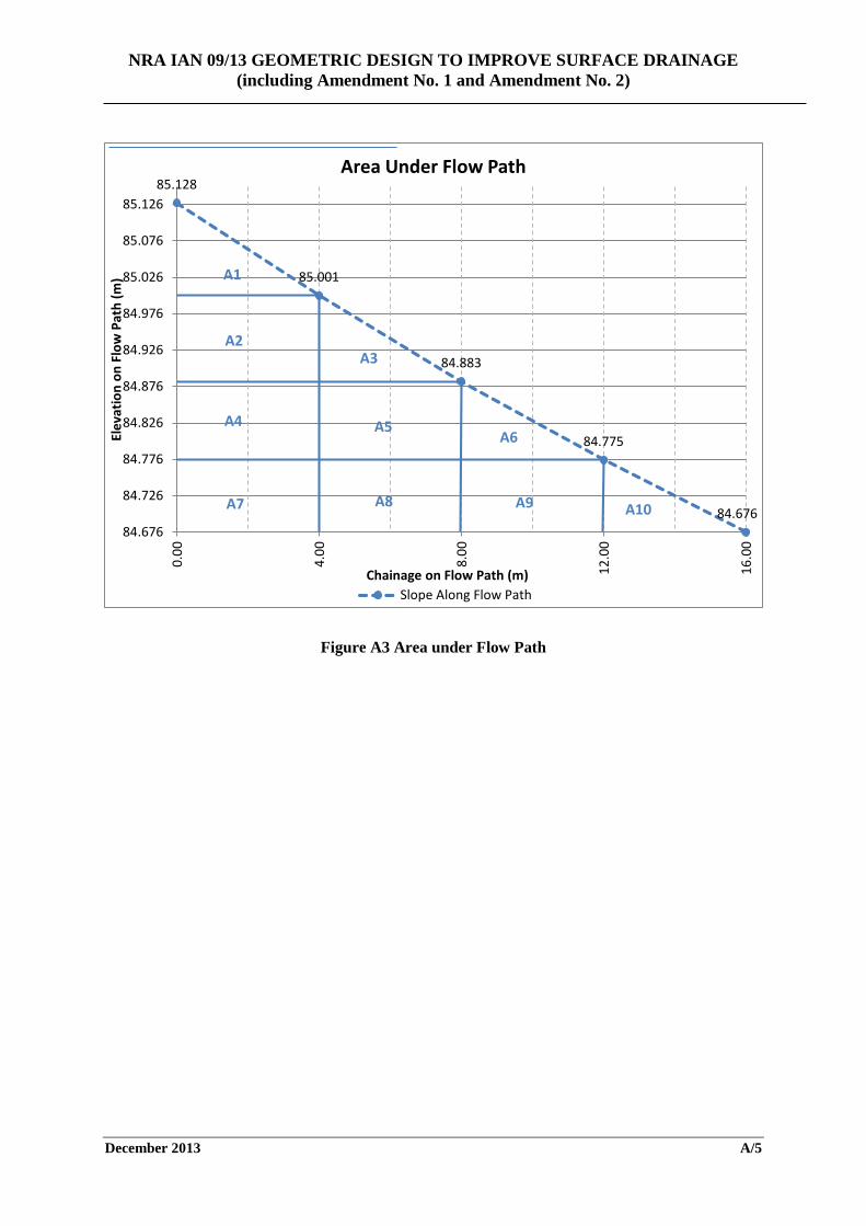
iv) Working in metres, the total area under the drainage flow path is calculated from the start up to the point of analysis. The total area can be calculated as a summation of the triangular/rectangular areas under the graph (see Figure A3). In this case, the total area under the profile up to the point of analysis is 3.428m2.
v) The vertical height of the Equal Area Triangle is then calculated by dividing the area by the length of the profile (16m) and multiplying by 2, giving a triangle height of 0.429m.
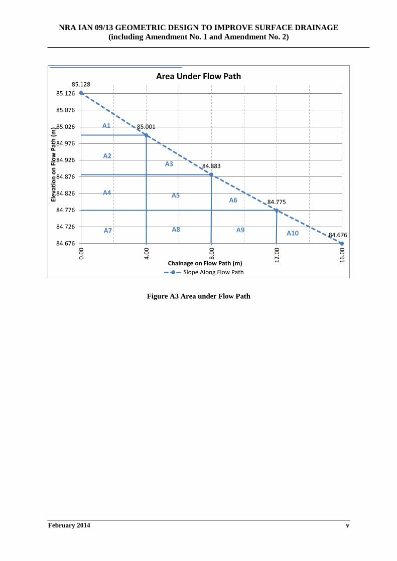
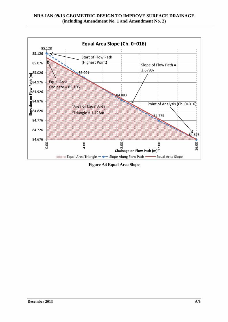
vi) The vertical ordinate of the Equal Area Triangle is determined by adding the triangle height to the flow path elevation at the point of analysis, resulting in a vertical ordinate of 85.105m (0.429m + 84.676m).
vii) This vertical ordinate is plotted at the highest point on the flow path (i.e. chainage 0) and joined back to the point of analysis at chainage 0+016m.
viii) The slope of this line is calculated and expressed as a percentage to give the Equal Area Slope at the point of analysis; in this case a slope of 2.678% is calculated at chainage 0+016m. A graphical summary of the calculation is presented in Figure A4 below.
85.128
85.001
84.883
84.775
84.67684.676
84.726
84.776
84.826
84.876
84.926
84.976
85.026
85.076
85.126
0.00
4.00
8.00
12.0
0
16.0
0
Elev
atio
n on
Flo
w P
ath
(m)
Chainage on Flow Path (m)
Drainage Flow Path
Slope Along Flow Path
NRA IAN 09/13 GEOMETRIC DESIGN TO IMPROVE SURFACE DRAINAGE (including Amendment No. 1 and Amendment No. 2)
February 2014 v
Figure A3 Area under Flow Path
85.128
85.001
84.883
84.775
84.67684.676
84.726
84.776
84.826
84.876
84.926
84.976
85.026
85.076
85.126
0.00
4.00
8.00
12.0
0
16.0
0
Elev
atio
n on
Flo
w P
ath
(m)
Chainage on Flow Path (m)
Area Under Flow Path
Slope Along Flow Path
A1
A2
A4
A3
A5A6
A7 A8 A9 A10
NRA IAN 09/13 GEOMETRIC DESIGN TO IMPROVE SURFACE DRAINAGE (including Amendment No. 1 and Amendment No. 2)
February 2014 vi
Figure A4 Equal Area Slope
85.128
85.001
84.883
84.775
84.67684.676
84.726
84.776
84.826
84.876
84.926
84.976
85.026
85.076
85.126
0.00
4.00
8.00
12.0
0
16.0
0
Elev
atio
n on
Flo
w P
ath
(m)
Chainage on Flow Path (m)
Equal Area Slope (Ch. 0+016)
Equal Area Triangle Slope Along Flow Path Equal Area Slope
Area of Equal Area Triangle = 3.428m
2
Equal Area Ordinate = 85.105
Start of Flow Path (Highest Point)
Point of Analysis (Ch. 0+016)
Slope of Flow Path = 2.678%
NRA IAN 09/13 GEOMETRIC DESIGN TO IMPROVE SURFACE DRAINAGE (including Amendment No. 1 and Amendment No. 2)
February 2014 vii
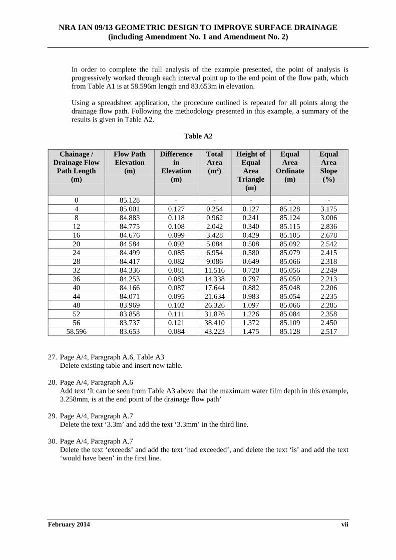
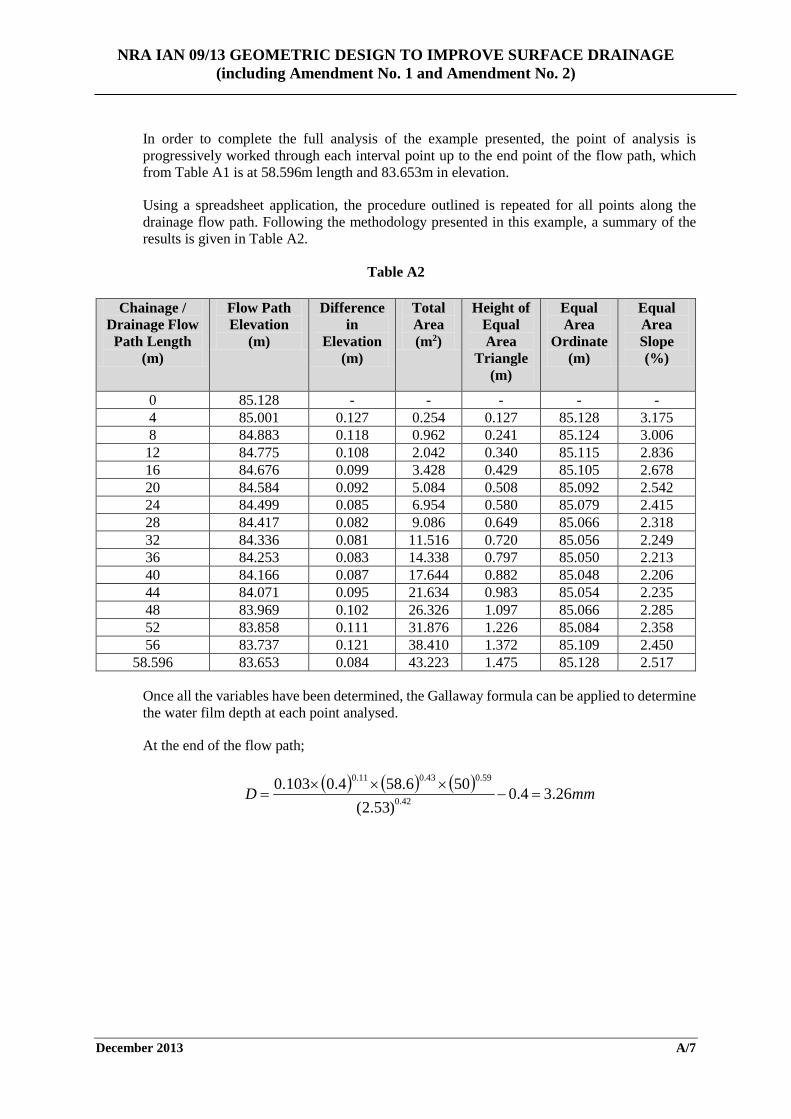
In order to complete the full analysis of the example presented, the point of analysis is progressively worked through each interval point up to the end point of the flow path, which from Table A1 is at 58.596m length and 83.653m in elevation.
Using a spreadsheet application, the procedure outlined is repeated for all points along the drainage flow path. Following the methodology presented in this example, a summary of the results is given in Table A2.
Table A2
Chainage / Drainage Flow Path Length
(m)
Flow Path Elevation
(m)
Difference in
Elevation (m)
Total Area (m2)
Height of Equal Area
Triangle (m)
Equal Area
Ordinate (m)
Equal Area Slope (%)
0 85.128 - - - - - 4 85.001 0.127 0.254 0.127 85.128 3.175 8 84.883 0.118 0.962 0.241 85.124 3.006
12 84.775 0.108 2.042 0.340 85.115 2.836 16 84.676 0.099 3.428 0.429 85.105 2.678 20 84.584 0.092 5.084 0.508 85.092 2.542 24 84.499 0.085 6.954 0.580 85.079 2.415 28 84.417 0.082 9.086 0.649 85.066 2.318 32 84.336 0.081 11.516 0.720 85.056 2.249 36 84.253 0.083 14.338 0.797 85.050 2.213 40 84.166 0.087 17.644 0.882 85.048 2.206 44 84.071 0.095 21.634 0.983 85.054 2.235 48 83.969 0.102 26.326 1.097 85.066 2.285 52 83.858 0.111 31.876 1.226 85.084 2.358 56 83.737 0.121 38.410 1.372 85.109 2.450
58.596 83.653 0.084 43.223 1.475 85.128 2.517
27. Page A/4, Paragraph A.6, Table A3
Delete existing table and insert new table. 28. Page A/4, Paragraph A.6
Add text ‘It can be seen from Table A3 above that the maximum water film depth in this example, 3.258mm, is at the end point of the drainage flow path’
29. Page A/4, Paragraph A.7
Delete the text ‘3.3m’ and add the text ‘3.3mm’ in the third line.
30. Page A/4, Paragraph A.7 Delete the text ‘exceeds’ and add the text ‘had exceeded’, and delete the text ‘is’ and add the text ‘would have been’ in the first line.
NRA IAN 09/13 GEOMETRIC DESIGN TO IMPROVE SURFACE DRAINAGE (including Amendment No. 1 and Amendment No. 2)
February 2014 viii
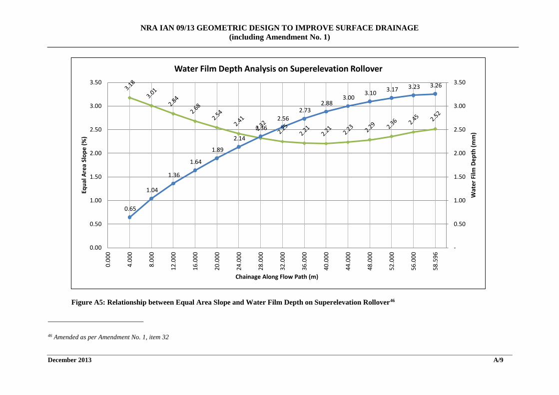
31. Page A/4, Paragraph A.8 Add a new paragraph including the text ‘For the flow path analysed, the relationship between Equal Area Slope and water film depth can be represented graphically from start to end chainage as per Figure A5 below’.
32. Page A/4, Paragraph A.8
Add new chart and add the text ‘Figure A5 Relationship between Equal Area Slope and Water Film Depth on Superelevation Rollover’.
NRA IAN 09/13 GEOMETRIC DESIGN TO IMPROVE SURFACE DRAINAGE (including Amendment No. 1 and Amendment No. 2)
December 2014 i
National Roads Authority
Interim Advice Note (NRA IAN)
AMENDMENT No. 2 (December 2014) to NRA IAN 09/13 Geometric Design to Improve Surface Drainage
Dated December 2013 NRA IAN 09/13 Geometric Design to Improve Surface Drainage Dated December 2013 is amended as follows:- 1. Page 1, Paragraph 1.1
Add the text ‘in the case of new build construction’ in the second and third lines.
2. Page 1, Paragraph 1.1 Delete the text ‘shall’ and insert the text ‘should’ from the fourth line.
3. Page 1, Paragraph 1.5 Delete the text ‘This Interim Advice Note shall be used for the design of all new or improved National Roads, including maintenance, reconstruction and widening projects’ from the second line’ and insert the text ‘This Interim Advice Note shall be used for the design of all new National Roads. The principles outlined are also applicable to projects involving the renewal, reconstruction or widening of national roads and to the assessment of surface drainage on existing carriageways. However, given that it will not be generally feasible to significantly alter longitudinal and transverse gradients on existing roads to meet the design criteria set out in this Interim Advice Note, the alternative methods set out in sections 3.36 to 3.43 of this advice note should be considered. Accordingly, in situations other than the design of new roads where the alignment is generally unrestrained, the design criteria set out should be viewed as guidance and not as mandatory requirements.’
4. Page 1, new Paragraph 1.6 Insert the text ‘Moreover, in the case of projects that have been designed and have received approval from An Bord Pleanála prior to the adoption of this Interim Advice Note, and which accordingly have defined geometries and land-take lines that cannot be altered, for such projects the alternative methods set out in sections 3.36 to 3.43 of this advice note should be considered’ as new paragraph 1.6.
5. Page 2, Paragraph 2.1 Delete the text ‘sufficiently adequate’ and insert the text ‘sufficient’ from the first line of replacement text.
6. Page 5, Paragraph 3.14 Delete the text ‘at texture levels above the mean level’ and insert the text ‘when it exceeds the mean texture depth’ from the tenth line.
NRA IAN 09/13 GEOMETRIC DESIGN TO IMPROVE SURFACE DRAINAGE (including Amendment No. 1 and Amendment No. 2)
December 2014 ii
7. Page 5, Paragraph 3.15 Delete the text ‘has to’ and insert the text ‘must’ from the first line.
8. Page 10, Paragraph 3.33 Delete the text ‘remedial measures’ and insert the text ‘design changes’ from the second line.
9. Page 10, Paragraph 3.33 Delete the text ‘Aquaplaning shall’ and insert the text ‘Avoidance of aquaplaning risk should’ from the sixth line.
10. Page 11, Paragraph 3.36 Delete the text ‘Where surface drainage problems exist and limiting water depths cannot be achieved by traditional methods, alternative methods can be used by the designer to satisfy the water depth criterion and thereby reduce the potential for aquaplaning to occur.’ and insert the text ‘Where surface drainage problems exist and limiting water depths cannot be achieved by the methods set out in this Interim Advice Note, alternative methods can be used to reduce the potential for aquaplaning to occur’ from the first line.
11. Page 11, Paragraph 3.36 Insert the text ‘In the case of existing road pavements, in particular, these two methods are likely to be the only practicable means of reducing surface water depths’ to the sixth line.
12. Page 13, Paragraph 3.38 Delete the text ‘Notwithstanding this, all other available methods for alleviating rollover drainage problems shall be exhausted by the designer before rolling crowns are adopted. Construction difficulties in achieving the gradients required and associated ride quality issues generally preclude the inclusion of rolling crowns as an acceptable solution and particular care should be taken in the design, specification and construction of such features’ and insert the text ‘Rolling crowns can present difficulties in achieving the required construction tolerances, specified gradients and satisfactory ride quality. As such, the use of rolling crowns is generally not the preferred solution for new road construction. However, when used, particular care should be taken in the design, specification and construction of such features’ from the first line.
13. Page 13, Paragraph 3.41 Delete the text ‘shall’ and insert the text ‘should’ from the fourth line.
14. Page 13, Paragraph 3.41, part i) Delete the text ‘shall’ and insert the text ‘should’ from the first line.
NRA IAN 09/13 GEOMETRIC DESIGN TO IMPROVE SURFACE DRAINAGE (including Amendment No. 1 and Amendment No. 2)
December 2013 A/1
APPENDIX A: WORKED EXAMPLE Assumptions and Methodology
A.1. The following example illustrates the recommended process to be followed by designers in determining the water film depth on a carriageway and assessing the potential for aquaplaning.
A.2. In this example, a calculation of the water film depth along the critical drainage flow path on a superelevation rollover section is required. In order to carry out the analysis, it is first necessary to produce an accurate contour model of the proposed road surface using three dimensional triangulation models34.
Assumptions
A.3. The following assumptions were required to carry out the assessment.
i) Standard Motorway (D2M) cross section with 120km/h design speed.
ii) Average pavement texture depth of 0.4mm.
iii) Rainfall intensity adopted for analysis is 50mm/hr.
iv) Road surface contours are as per figure A1 below.
v) A 4m distance has been adopted as the interval in this example for simplicity. An interval of 1m should be considered by the designer when carrying out a more detailed analysis35.
Methodology
Step 1:
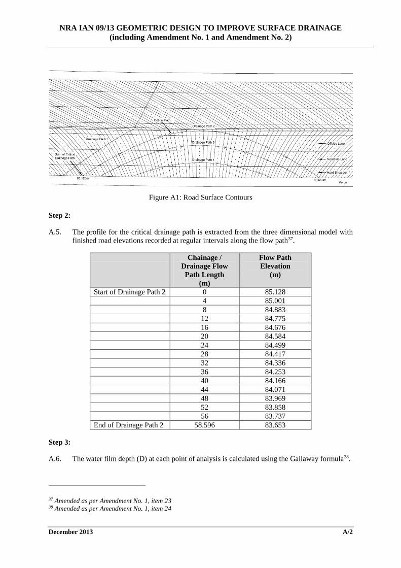
A.4. Review the contour plan of the proposed road surface and identify the critical drainage flow path.
i) Drainage path 1 represents the flow path with superelevation still applied, with water flowing from one side of the carriageway to the other and is not the critical path.
ii) Drainage paths 2, 3 and 4 all start on one side of the carriageway, travel towards the other side but then turn back (due to the superelevation rotation) and drain off on the same side of the carriageway as they started36.
iii) The longest path is considered the critical path; therefore drainage path 2 is assessed to determine the water film depth.
34 Amended as per Amendment No. 1, item 20 35 Amended as per Amendment No. 1, item 21 36 Amended as per Amendment No. 1, item 22
NRA IAN 09/13 GEOMETRIC DESIGN TO IMPROVE SURFACE DRAINAGE (including Amendment No. 1 and Amendment No. 2)
December 2013 A/2
Figure A1: Road Surface Contours
Step 2:
A.5. The profile for the critical drainage path is extracted from the three dimensional model with finished road elevations recorded at regular intervals along the flow path37.
Chainage / Drainage Flow
Path Length (m)
Flow Path Elevation
(m)
Start of Drainage Path 2 0 85.128 4 85.001 8 84.883 12 84.775 16 84.676 20 84.584 24 84.499 28 84.417 32 84.336 36 84.253 40 84.166 44 84.071 48 83.969 52 83.858 56 83.737 End of Drainage Path 2 58.596 83.653
Step 3:
A.6. The water film depth (D) at each point of analysis is calculated using the Gallaway formula38.
37 Amended as per Amendment No. 1, item 23 38 Amended as per Amendment No. 1, item 24
NRA IAN 09/13 GEOMETRIC DESIGN TO IMPROVE SURFACE DRAINAGE (including Amendment No. 1 and Amendment No. 2)
December 2013 A/3
TS
ILTD −×××
= 42.0
59.043.011.0103.0
The rainfall intensity, I, adopted for the analysis is 50mm/hr (refer to section 3.26).
The average pavement texture depth, T, is assumed to be 0.4mm taking into account future degradation of the pavement surface39.
40The length of the drainage flow path, L, at the each point of analysis is given in Table A1 above.
The slope to the point of analysis is the calculated ‘Equal Area Slope’ as per the procedure outlined in sections 3.28 and 3.29.
Application of Methodology
The calculation of water film depth must be undertaken at each interval point on the drainage flow path, to establish where on the drainage flow path the maximum water film depth exists.
For convenience and to demonstrate the procedure to be followed a point of analysis has been chosen (16m) and the Equal Area Slope is calculated at this point on the flow path. Using the values in Table A1 and the procedure described in section 3.29;
i) The profile of the flow path is plotted from the highest point at the start of the drainage path up to the point of analysis (see Figure A2 below).
39 Amended as per Amendment No. 1, item 25 40 Amended as per Amendment No. 1, item 26
NRA IAN 09/13 GEOMETRIC DESIGN TO IMPROVE SURFACE DRAINAGE (including Amendment No. 1 and Amendment No. 2)
December 2013 A/4
Figure A2 Profile of Drainage Flow Path
ii) Working in metres, the total area under the drainage flow path is calculated from the start up to the point of analysis. The total area can be calculated as a summation of the triangular/rectangular areas under the graph (see Figure A3). In this case, the total area under the profile up to the point of analysis is 3.428m2.
iii) The vertical height of the Equal Area Triangle is then calculated by dividing the area by the length of the profile (16m) and multiplying by 2, giving a triangle height of 0.429m.
iv) The vertical ordinate of the Equal Area Triangle is determined by adding the triangle height to the flow path elevation at the point of analysis, resulting in a vertical ordinate of 85.105m (0.429m + 84.676m).
v) This vertical ordinate is plotted at the highest point on the flow path (i.e. chainage 0) and joined back to the point of analysis at chainage 0+016m.
vi) The slope of this line is calculated and expressed as a percentage to give the Equal Area Slope at the point of analysis; in this case a slope of 2.678% is calculated at chainage 0+016m. A graphical summary of the calculation is presented in Figure A4 below.
85.128
85.001
84.883
84.775
84.67684.676
84.726
84.776
84.826
84.876
84.926
84.976
85.026
85.076
85.126
0.00
4.00
8.00
12.0
0
16.0
0
Elev
atio
n on
Flo
w P
ath
(m)
Chainage on Flow Path (m)
Drainage Flow Path
Slope Along Flow Path
NRA IAN 09/13 GEOMETRIC DESIGN TO IMPROVE SURFACE DRAINAGE (including Amendment No. 1 and Amendment No. 2)
December 2013 A/5
Figure A3 Area under Flow Path
85.128
85.001
84.883
84.775
84.67684.676
84.726
84.776
84.826
84.876
84.926
84.976
85.026
85.076
85.126
0.00
4.00
8.00
12.0
0
16.0
0
Elev
atio
n on
Flo
w P
ath
(m)
Chainage on Flow Path (m)
Area Under Flow Path
Slope Along Flow Path
A1
A2
A4
A3
A5A6
A7 A8 A9 A10
NRA IAN 09/13 GEOMETRIC DESIGN TO IMPROVE SURFACE DRAINAGE (including Amendment No. 1 and Amendment No. 2)
December 2013 A/6
Figure A4 Equal Area Slope
85.128
85.001
84.883
84.775
84.67684.676
84.726
84.776
84.826
84.876
84.926
84.976
85.026
85.076
85.126
0.00
4.00
8.00
12.0
0
16.0
0
Elev
atio
n on
Flo
w P
ath
(m)
Chainage on Flow Path (m)
Equal Area Slope (Ch. 0+016)
Equal Area Triangle Slope Along Flow Path Equal Area Slope
Area of Equal Area Triangle = 3.428m
2
Equal Area Ordinate = 85.105
Start of Flow Path (Highest Point)
Point of Analysis (Ch. 0+016)
Slope of Flow Path = 2.678%
NRA IAN 09/13 GEOMETRIC DESIGN TO IMPROVE SURFACE DRAINAGE (including Amendment No. 1 and Amendment No. 2)
December 2013 A/7
In order to complete the full analysis of the example presented, the point of analysis is progressively worked through each interval point up to the end point of the flow path, which from Table A1 is at 58.596m length and 83.653m in elevation.
Using a spreadsheet application, the procedure outlined is repeated for all points along the drainage flow path. Following the methodology presented in this example, a summary of the results is given in Table A2.
Table A2
Chainage / Drainage Flow Path Length
(m)
Flow Path Elevation
(m)
Difference in
Elevation (m)
Total Area (m2)
Height of Equal Area
Triangle (m)
Equal Area
Ordinate (m)
Equal Area Slope (%)
0 85.128 - - - - - 4 85.001 0.127 0.254 0.127 85.128 3.175 8 84.883 0.118 0.962 0.241 85.124 3.006
12 84.775 0.108 2.042 0.340 85.115 2.836 16 84.676 0.099 3.428 0.429 85.105 2.678 20 84.584 0.092 5.084 0.508 85.092 2.542 24 84.499 0.085 6.954 0.580 85.079 2.415 28 84.417 0.082 9.086 0.649 85.066 2.318 32 84.336 0.081 11.516 0.720 85.056 2.249 36 84.253 0.083 14.338 0.797 85.050 2.213 40 84.166 0.087 17.644 0.882 85.048 2.206 44 84.071 0.095 21.634 0.983 85.054 2.235 48 83.969 0.102 26.326 1.097 85.066 2.285 52 83.858 0.111 31.876 1.226 85.084 2.358 56 83.737 0.121 38.410 1.372 85.109 2.450
58.596 83.653 0.084 43.223 1.475 85.128 2.517
Once all the variables have been determined, the Gallaway formula can be applied to determine the water film depth at each point analysed.
At the end of the flow path;
( ) ( ) ( ) mmD 26.34.0)53.2(
506.584.0103.042.0
59.043.011.0
=−×××
=
NRA IAN 09/13 GEOMETRIC DESIGN TO IMPROVE SURFACE DRAINAGE (including Amendment No. 1 and Amendment No. 2)
December 2013 A/8
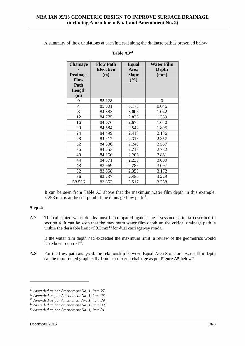
A summary of the calculations at each interval along the drainage path is presented below:
Table A341
Chainage /
Drainage Flow Path
Length (m)
Flow Path Elevation
(m)
Equal Area Slope (%)
Water Film Depth (mm)
0 85.128 - 0 4 85.001 3.175 0.646 8 84.883 3.006 1.042 12 84.775 2.836 1.359 16 84.676 2.678 1.640 20 84.584 2.542 1.895 24 84.499 2.415 2.136 28 84.417 2.318 2.357 32 84.336 2.249 2.557 36 84.253 2.213 2.732 40 84.166 2.206 2.881 44 84.071 2.235 3.000 48 83.969 2.285 3.097 52 83.858 2.358 3.172 56 83.737 2.450 3.229
58.596 83.653 2.517 3.258
It can be seen from Table A3 above that the maximum water film depth in this example, 3.258mm, is at the end point of the drainage flow path42.
Step 4:
A.7. The calculated water depths must be compared against the assessment criteria described in section 4. It can be seen that the maximum water film depth on the critical drainage path is within the desirable limit of 3.3mm43 for dual carriageway roads.
If the water film depth had exceeded the maximum limit, a review of the geometrics would have been required44.
A.8. For the flow path analysed, the relationship between Equal Area Slope and water film depth can be represented graphically from start to end chainage as per Figure A5 below45.
41 Amended as per Amendment No. 1, item 27 42 Amended as per Amendment No. 1, item 28 43 Amended as per Amendment No. 1, item 29 44 Amended as per Amendment No. 1, item 30 45 Amended as per Amendment No. 1, item 31
NRA IAN 09/13 GEOMETRIC DESIGN TO IMPROVE SURFACE DRAINAGE (including Amendment No. 1)
December 2013 A/9
Figure A5: Relationship between Equal Area Slope and Water Film Depth on Superelevation Rollover46
46 Amended as per Amendment No. 1, item 32
0.65
1.04
1.36
1.64
1.89
2.14 2.36
2.56 2.73
2.88 3.00
3.10 3.17 3.23 3.26
-
0.50
1.00
1.50
2.00
2.50
3.00
3.50
0.00
0.50
1.00
1.50
2.00
2.50
3.00
3.50
0.00
0
4.00
0
8.00
0
12.0
00
16.0
00
20.0
00
24.0
00
28.0
00
32.0
00
36.0
00
40.0
00
44.0
00
48.0
00
52.0
00
56.0
00
58.5
96
Wat
er F
ilm D
epth
(mm
)
Equa
l Are
a Sl
ope
(%)
Chainage Along Flow Path (m)
Water Film Depth Analysis on Superelevation Rollover


Ionad Ghnó Gheata na
Páirce,
Stráid Gheata na Páirce, Baile Átha Cliath 8, Éire
www.tii.ie
+353 (01) 646 3600
Parkgate Business Centre,
Parkgate Street,
Dublin 8, Ireland
+353 (01) 646 3601


![CREATION OF AN INTEG RATED OPTIMAL URBAN DRAINAGE NETWO RK ... · PDF fileStatement of Hydraulic ... Incremental Increase Method and Geometric Progression Method [2]. For sewerage](https://img.pdfslide.net/doc/110x75/5aa365657f8b9a436d8e1e5e/creation-of-an-integ-rated-optimal-urban-drainage-netwo-rk-of-hydraulic-.jpg)