Embed Size (px)
Citation preview

Geometric Linear And Nonlinear Analysis Of Beam Mr. Kashinath N. Borse1, ShailendrakumarDubey 2
1 M.E. Student, Civil Engg.Dept. S.S.V.P.S BSD College of Engg, Dhule, India 2 Associate Professor, Civil Engg.Dept. S.S.V.P.S BSD College of Engg, Dhule, India
ABSTRACT:-
The beams are structural elements with thickness smaller than other plan dimensions. These structural elements are
used in vast varieties of structures. Hence analysis of beams becomes the topic of interest for civil, mechanical,
aeronautical and marine engineer. Now a day’s steel is an economic and useful material, almost all the structural
members are constructed by steel compare to timber and concrete. With the development of construction and
manufacturing technology, beams of different shapes and varied sizes are demanded by designers. Analysis of these
beams and thin plate attracted attention of many researchers. This paper is addressed to the review of advances,
techniques and theoretical background of the non-linear analysis of steel beam. The formulation of beam element in
bending has constituted the most exiting area in the development of the solution techniques. If the structure (beams)
is made slender along, with bending, membrane action starts coming in picture .The aim of non linear analysis is to
predict deflection of beam at various load stages. For present paper two nodes beam element is used for formulation
of linear and geometric nonlinear analysis. In the present paper deflection of thin beam is obtained by finite element
method in SAP software. The behavior of these flexure members in linear analysis and nonlinear analysis are
compared. Some numeric examples are solved.
Keywords: - Finite element method, Steel beam, SAP2000.
INTRODUCTION
Structure is a free-standing, immobile outdoor construction. Typical examples include buildings and non-building
structures such as bridges, dams, missile launching tower, transmission line towers. Most of structures are
permanent though some structures are temporary, built for some events such as launching pads for spacecrafts, trade
shows, conferences or theatre, and often dismantled after use. Temporary structures have fewer constraints relating
to future use and durability thus these structures may be made slender and thinner. The flexure members of a
structure, namely, beams and plates exhibit linear behavior till deflections are small compared to their thicknesses.
As deflections increase, membrane forces are introduced and the external transverse load is supported by membrane-
bending action. From this paper one can learn about the differences between linear and non-linear analysis and
realize that there are optimum times to use one type of analysis versus the other.
Linear Analysis
Linear analysis (first order analysis) is also known as linear elastic analysis. The term of Elastic means that when the
structure is unloaded it follows the same deformation path as when loaded. A linear FEA analysis is undertaken
when a structure is expected to behave linearly, i.e. obeys Hook’s Law. The stress is proportional to the strain, and
the structure will return to its original configuration once the load has been removed. A structure is a load bearing
member and can normally classified as a bar, beam, column or shaft. In linear elastic analysis, the material is
assumed to be unyielding and its properties invariable and the equations of equilibrium are formulated on the
geometry of the unloaded structure. It is assumed that the subsequent deflections will be small and will have
insignificant effect on the stability and mode of response of the structure. The linear analysis of the beam and thin
plate is done using stiffness method. In this approach the primary unknowns are the joint displacements, which are
determined first by solving the structure equation of equilibrium. Then the unknown forces can be obtained through
compatibility consideration.
Formulation Linear analysis of beam
A beam is a member predominantly supporting applied load by flexural strength of it. Fig.1 (a) shows a typical beam
with its discretisation. Here beam is discretised in elements. The beam is discretised in four elements and having
five nodes. Take a typical beam element shown in Fig. (b). It has two nodes, for generating formulation slope and
deflection at each node is required.
415
International Journal of Engineering Research & Technology (IJERT)
Vol. 2 Issue 7, July - 2013
IJERT
IJERT
ISSN: 2278-0181
www.ijert.orgIJERTV2IS70212

Fig.1:Typical beam and element
In case of two dimensional structures, the displacement at any point can be expressed by its components w, dw
dx which are continues function of x.
Therefore, degree of freedom per joint = 2 (i.e. w, 𝑑𝑤
𝑑𝑥)
The displacement within element at any point p(x) can be as follows
The variation of in plane displacement w,
dx
dware prescribe using shape functions –
2
222
1
111
x
wNwN
x
wNwNwp
N and N are Hermition shape function
2211 NNNNwp
eNw
The linear strains resultant within element can be written as
2
2
x
wX
2
2
2
2
22
2
2
1
2
1
2
12
1
2
x
w
x
Nw
x
N
x
w
x
Nw
x
N
ex
N
x
N
x
N
x
N
2
2
2
2
2
2
2
1
2
2
1
2
eBX
The linear stress resultant i.e. Moment within element can be express as
XEIM
XDM
Strain energy within element is calculated using strain energy over tiny length within element.
MXdUT
2
1
Then it is integrated over entire element. Thus the strain energy over entire length is
416
International Journal of Engineering Research & Technology (IJERT)
Vol. 2 Issue 7, July - 2013
IJERT
IJERT
ISSN: 2278-0181
www.ijert.orgIJERTV2IS70212

dxMXU
LT
0
2
1
dxeBDBeU
LTT
0
2
1
dxeBDBeU
LTT
02
1
From the above the element stiffness matrix can be extract as follows
LT
dxBDBSe0
Non-Linear Analysis
Typical geometric nonlinearity arises from mid plane stretching of a thin structure coupled with transverse
vibrations or loading. This stretching leads to a nonlinear relationship between the strain and the displacement. In
mathematics, non-linear systems represent systems whose behavior is not expressible as a sum of the behaviors
of its descriptors. In particular, the behavior of non-linear systems is not subjected to the principle of
superposition, as linear systems. Crudely, a non-linear system is one whose behavior is not simply the sum of
its parts or their multiples.
Formulation of non-linear analysis of beam
The non-linear analysis of beam is due to the bending of beam, and due to thin thickness of beam the neutral axis of
beam is stretched due to this additional axial force is induced in the beam Fig.2 Shows a typical element having
length L. it has same thickness throughout its length. It has two nodes and also shows the displacement in x direction
and y direction are u and w respectively.
Fig. 2: Typical nonlinear beam element
In nonlinear analysis each node of a beam element has three degree of freedom in x direction and z direction
Degree of freedom per joint = u, w, 𝑑𝑤
𝑑𝑥
u displacement due to axial force
w, 𝑑𝑤
𝑑𝑥 displacement due to bending
𝛿𝑒 = 𝑢1 , 𝑤1 ,𝑑𝑤1
𝑑𝑥, 𝑢2, 𝑤2 ,
𝑑𝑤2
𝑑𝑥 𝑇
The displacement within element at any point p(x) can be as follows.
The variations of in plane displacement u, w, 𝑑𝑤 𝑑𝑥 are prescribing using shape functions. Fig. 3 shows u1 and u2
displacements in x direction
417
International Journal of Engineering Research & Technology (IJERT)
Vol. 2 Issue 7, July - 2013
IJERT
IJERT
ISSN: 2278-0181
www.ijert.orgIJERTV2IS70212

Fig. 3: Typical Non-Linear beam element
𝑈𝑝 = 𝑙1𝑢1 + 𝑙2𝑢2
2
222
1
111
x
wNwN
x
wNwNwp
Where,
l1and l2 are Lagrangian shape function in x direction
𝑙1 = 1 − 𝑥 𝑎 and𝑙2 = 𝑥 𝑎
The Non-Linear strains resultant within element can be written as
€𝑝 = 𝜕𝑢0
𝜕𝑥+
1
2 𝑑𝑤
𝑑𝑥
2
The strains resultant is taken from the theory of elasticity, due to stretching of neutral axis the point p is also
displace in z direction. The displacement of a point at distance
z from the middle plane can be as fig.4 shows the displacement of point p in u and z direction.
Fig.4: Displacement of point p in x and z direction
𝑢 𝑧 = 𝑢 − 𝑧 𝜕𝑤
𝜕𝑥
𝑤 𝑧 = 𝑤
Now substitute the nodal displacements in strain resultant
€𝑝 = 𝜕𝑢
𝜕𝑥− 𝑧
𝑑2𝑤
𝑑𝑥2+
1
2 𝜕𝑤
𝜕𝑥
2
Where, 𝜕𝑢
𝜕𝑥 is constant across the thickness of beam,𝑧
𝑑2𝑤
𝑑𝑥 2 is varies with Z distance
Strain resultant due to axial force within element
€𝑝 = 𝜕𝑢
𝜕𝑥+
1
2 𝜕𝑤
𝜕𝑥
2
Strain resultant due to bending within element €𝑝 = −𝑧𝑑2𝑤
𝑑𝑥 2
Therefore 𝜒𝑏 = (−)𝑑2𝑤
𝑑𝑥 2
The linear stress resultant i.e. Moment within element can be express as
Axial force within element
{N} = [EA] {€p}
418
International Journal of Engineering Research & Technology (IJERT)
Vol. 2 Issue 7, July - 2013
IJERT
IJERT
ISSN: 2278-0181
www.ijert.orgIJERTV2IS70212

Moment within Element
{𝑀} = 𝐸𝐼 𝜒𝑏
Therefore stress resultant is written in the matrix form is as follows.
𝑁𝑀
= 𝐸𝐴 00 𝐸𝐼
€𝑃
𝜒𝑏
NUMERICAL EXAMPLES
To check the validity of the present formulation, some examples are solved by using computer program i.e. Simply-
supported beam subjected to a center point load, the beam has a length (L) 700mm, width (b)50mm and depth (h)
10mm,05mm.
Behavior of geometric nonlinear Example-
(a)Simply supported beam (b) cross section of beam
Fig.5: Simply supported beam and its cross section
The simply supported beam over uniformed distributed load is increase gradually in this cases non-linearity
so very large it shows following cases
The deflection of beam by theoretical calculated formula is given below
EI
wL
48
3
The above formula is most suitable for calculating deflections of linear analysis for thick beam. For thin beams this
formula is not suitable. Hence we use SAP software for calculated nonlinear analysis.
Case 1- Thickness of beam = t = 10 mm
Table 1: Loading and deflection for thickness 10 mm
Load in
KN
Deflection ∆ (mm)
% of variation SAP Linear and
Nonlinear Theoretical Calculation
Linear Analysis Nonlinear Analysis
Difference SAP Linear and Theoretical
Difference Linear and Nonlinear
0.25 2.143748285 2.1448 2.144725 7.5E-05 0.001051715 0.00349683
0.50 4.28749657 4.2896 4.28899 0.00061 0.00210343 0.01422044
0.75 6.431244855 6.4344 6.432341 0.002059 0.003155145 0.031999876
1.00 8.57499314 8.5792 8.574322 0.004878 0.00420686 0.056858448
1.25 10.71874143 10.724 10.714478 0.009522 0.005258575 0.088791496
1.50 12.86248971 12.8688 12.852357 0.016443 0.00631029 0.127774151
1.75 15.006238 15.0136 14.987513 0.026087 0.007362005 0.173755795
2.00 17.14998628 17.1584 17.119498 0.038902 0.00841372 0.226722771
W KN
L/
2
L/
2
b
h L
419
International Journal of Engineering Research & Technology (IJERT)
Vol. 2 Issue 7, July - 2013
IJERT
IJERT
ISSN: 2278-0181
www.ijert.orgIJERTV2IS70212

2.25 19.29373457 19.3032 19.247873 0.055327 0.009465435 0.286620871
2.50 21.43748285 21.448 21.372202 0.075798 0.01051715 0.353403581
2.75 23.58123114 23.5928 23.492049 0.100751 0.011568865 0.427041301
3.00 25.72497942 25.7376 25.606997 0.130603 0.01262058 0.507440476
3.25 27.86872771 27.8824 27.716623 0.165777 0.013672295 0.594557857
3.50 30.01247599 30.0272 29.820515 0.206685 0.01472401 0.688325918
3.75 32.15622428 32.172 31.918269 0.253731 0.015775725 0.788670272
4.00 34.29997256 34.3168 34.009487 0.307313 0.01682744 0.895517647
4.25 36.44372085 36.4616 36.10506233 0.356537667 0.017879155 0.977844271
4.50 38.58746913 38.6064 38.19954833 0.406851667 0.01893087 1.053845131
4.75 40.73121742 40.7512 40.29403433 0.457165667 0.019982585 1.121845901
5.00 42.8749657 42.896 42.301354 0.594646 0.0210343 1.386250466
6.00 51.44995884 51.4752 50.459134 1.016066 0.02524116 1.973894225
7.00 60.02495198 60.0544 58.461846 1.592554 0.02944802 2.651852321
8.00 68.59994512 68.6336 66.29217 2.34143 0.03365488 3.41149233
9.00 77.17493826 77.2128 73.9318 3.281 0.03786174 4.249295454
10.00 85.7499314 85.792 81.370995 4.421005 0.0420686 5.153166962
11 94.32492454 94.3712 88.598738 5.772462 0.04627546 6.116762317
12 102.8999177 102.9504 95.608059 7.342341 0.05048232 7.131920808
13 111.4749108 111.5296 102.39405 9.13555 0.05468918 8.191143876
14 120.049904 120.1088 108.954105 11.154695 0.05889604 9.287158809
15 128.6248971 128.688 115.287572 13.400428 0.0631029 10.41311389
16 137.1998902 137.2672 121.395496 15.871704 0.06730976 11.56263405
17 145.7748834 145.8464 127.280368 18.566032 0.07151662 12.72985278
18 154.3498765 154.4256 132.945884 21.479716 0.07572348 13.90942693
19 162.9248697 163.0048 138.396568 24.608232 0.07993034 15.09663028
20 171.4998628 171.584 143.63108 27.95292 0.0841372 16.2910994
420
International Journal of Engineering Research & Technology (IJERT)
Vol. 2 Issue 7, July - 2013
IJERT
IJERT
ISSN: 2278-0181
www.ijert.orgIJERTV2IS70212

Case 1- Thickness of beam = t = 5 mm
Table 2: Loading and deflection for thickness 5 mm
Load in KN
Deflection ∆ (mm) % of variation SAP
Linear and
Nonlinear Theoretical
Calculation Linear Analysis
Nonlinear
Analysis
Difference SAP Linear
and Theoretical
Difference Linear and
Nonlinear
00.25 17.15010985 17.1521 17.113226 0.038874 0.00199015 0.226642802
00.50 34.3002197 34.3042 33.997099 0.307101 0.0039803 0.895228573
00.75 51.45032955 51.4563 50.440925 1.015375 0.00597045 1.973276353
01.00 68.6004394 68.6084 66.267603 2.340797 0.0079606 3.411822751
01.25 85.75054925 85.7605 81.342251 4.418249 0.00995075 5.15184613
01.50 102.9006591 102.9126 95.514867 7.397733 0.0119409 7.18836469
01.75 120.050769 120.0647 108.916793 11.147907 0.01393105 9.284916383
02.00 137.2008788 137.2168 121.354369 15.862431 0.0159212 11.5601231
02.25 154.3509887 154.3689 132.901244 21.467656 0.01791135 13.90672344
02.50 171.5010985 171.521 143.590376 27.930624 0.0199015 16.28408416
02.75 188.6512084 188.6731 153.467391 35.205709 0.02189165 18.65963351
03.00 205.8013182 205.8252 162.585132 43.240068 0.0238818 21.00815061
03.25 222.9514281 222.9773 170.999589 51.977711 0.02587195 23.31076347
03.50 240.1015379 240.1294 178.167026 61.962374 0.0278621 25.80374332
03.75 257.2516478 257.2815 185.941889 71.339611 0.02985225 27.72823192
04.00 274.4017576 274.4336 192.576189 81.857411 0.0318424 29.82776562
04.25 291.5518675 291.5857 198.718131 92.867569 0.03383255 31.8491507
04.50 308.7019773 308.7378 204.412236 104.325564 0.0358227 33.79099158
04.75 325.8520872 325.8899 209.699207 116.190693 0.03781285 35.65335808
05.00 343.002197 343.042 214.616032 128.425968 0.039803 37.43738901
06.00 411.6026364 411.6504 231.203951 180.446449 0.0477636 43.8348776
07.00 480.2030758 480.2588 244.024701 236.234099 0.0557242 49.18891627
08.00 548.8035152 548.8672 254.187124 294.680076 0.0636848 53.68877499
09.00 617.4039546 617.4756 262.427523 355.048077 0.0716454 57.49993635
10.00 686.004394 686.084 269.24404 416.83996 0.079606 60.75640301
11.00 754.6048334 754.6924 274.983056 479.709344 0.0875666 63.56355835
12.00 823.2052728 823.3008 279.888113 543.412687 0.0955272 66.00414903
13.00 891.8057122 891.9092 284.136646 607.772554 0.1034878 68.14287306
14.00 960.4061516 960.5176 287.859374 672.658226 0.1114484 70.03080693
15.00 1029.006591 1029.126 291.154627 737.971373 0.119409 71.70855396
16.00 1097.60703 1097.7344 294.09753 803.63687 0.1273696 73.20868053
17.00 1166.20747 1166.3428 296.746422 869.596378 0.1353302 74.55752957
18.00 1234.807909 1234.9512 299.147179 935.804021 0.1432908 75.77659919
19.00 1303.408349 1303.5596 301.336401 1002.223199 0.1512514 76.88357318
20.00 1372.008788 1372.168 303.3436 1068.8244 0.159212 77.89311513
421
International Journal of Engineering Research & Technology (IJERT)
Vol. 2 Issue 7, July - 2013
IJERT
IJERT
ISSN: 2278-0181
www.ijert.orgIJERTV2IS70212
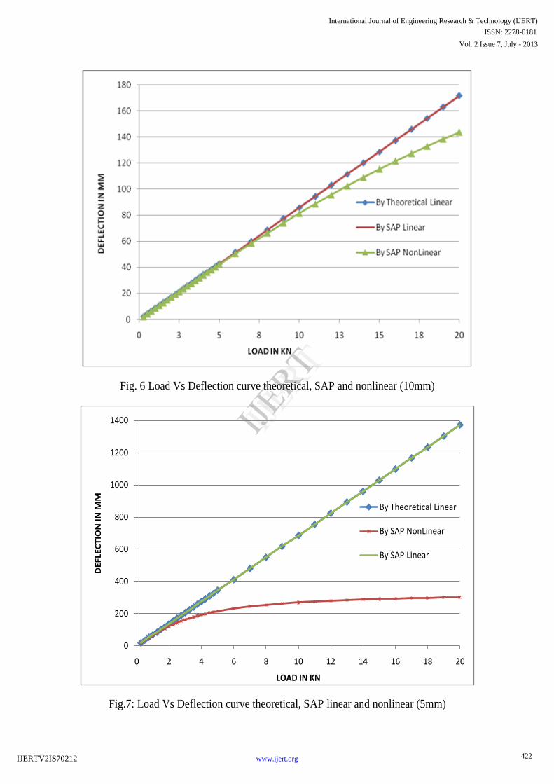
Fig. 6 Load Vs Deflection curve theoretical, SAP and nonlinear (10mm)
Fig.7: Load Vs Deflection curve theoretical, SAP linear and nonlinear (5mm)
0
200
400
600
800
1000
1200
1400
0 2 4 6 8 10 12 14 16 18 20
DE
FLE
CT
ION
IN
MM
LOAD IN KN
By Theoretical Linear
By SAP NonLinear
By SAP Linear
422
International Journal of Engineering Research & Technology (IJERT)
Vol. 2 Issue 7, July - 2013
IJERT
IJERT
ISSN: 2278-0181
www.ijert.orgIJERTV2IS70212

CONCLUSIONS:-
The general purpose finite element software SAP2000 was used to conduct the linear and nonlinear analysis. Certain
examples are analysed by SAP2000 and the results are compared with theoretical calculation.The studies on
Software and theoretical results associated with them lead to the following conclusions:
1. When loads intensity is small there is a very small (Negligible) variation between theoretical and SAP
2000in linear deflection.
2. P-delta value shows the significant geometric nonlinear analysis as compared to the linear analysis in this
study.
3. Geometric nonlinearity is not induced in the thick beam when the load intensity is small and it is induced in
the thick beam when the big load intensity goes on increasing.
4. Geometric nonlinearity is induced in the beam because of its lesser thickness (thinner). it is produced more
in the thinner beam, when load is increased.
5. As the stretching of middle plane (Neutral axis) starts, the stiffness of structure increases (axial stiffness is
added with bending stiffness).Thus the beam becomes stiffer progressively. It is a positive aspect of
geometric nonlinearity.
References 1) Timoshenko S.P. and Gere J.M., 'Theory of elastic stability’, second edition McGraw- Hill publishing company limited, New Delhi
,1963.
2) Timoshenko S.P. and Gere J.M., 'Theory of plates and shell’, second edition Mcgraw- hill publishing company limited, New York,
1959.
3) BasuAmiya Kumar, Champman John and Clifford Lavy S., 'Large deflection behavior of transversely loaded rectangular plate', Proc.
Inst. Civil Engg., London ., vol.35, 79-110,1966.
4) Murray David W, and Wilson Edward., 'Finite element large deflection in analysis of beam and plates', Proc. ASCE Strut. Div.,
95,143-165, 1969.
5) Meghre A.S. and Kadam K.N., ‘Geometric nonlinearity of thin rectangular plates using FEM cum FDEM approach’. Jr .of Inst. of
Engineers. vol. 78, 158-162, Feb 1998.
6) Kadam K.N., 'Geometric non linear analysis of thin rectangular plate using FEM Cum FDEM '. Dissertation, Government College of
Engineering, Amravati,1994.
7) Zienkiewicz O.C., 'Finite element method', 3rd edition, Mcgraw Hill, London, 1977
8) Bushnell David, Almroth B.O. and Brogan F., 'Finite difference energy method for nonlinear shell analysis’.Int .J. Comp. struct,
vol.1,3., 361-389,1971.
9) Cheung M.S. and Weinchang Li., ‘A modified finite strip method for geometrically nonlinear analysis of plate’, Comp.Strut.vol.33,
1031-1035, 1989.
423
International Journal of Engineering Research & Technology (IJERT)
Vol. 2 Issue 7, July - 2013
IJERT
IJERT
ISSN: 2278-0181
www.ijert.orgIJERTV2IS70212


![The Content Validity of the Cultural Formulation Interview ...downloads.hindawi.com/journals/psychiatry/2018/3082823.pdfPsychiatryJournal [] C. H. Lawshe, “A quantitative approach](https://img.pdfslide.net/doc/110x75/5f4358d4f233eb18b136f02d/the-content-validity-of-the-cultural-formulation-interview-psychiatryjournal.jpg)